

Husqvarna 420, 430X, 440, 450X Operator’s Manual
EN, English
Operator's manual
HUSQVARNA AUTOMOWER
®
420/430X/440/450X
Read the operator's manual carefully and make sure that you
understand the instructions before you use the product.

Contents
1 Introduction
1.1 Introduction.................................................3
1.2 Product overview .......................................4
1.3 Symbols on the product..............................5
1.4 Symbols on the display.............................. 5
1.5 Symbols on the battery...............................6
1.6 General manual instructions.......................6
1.7 Menu structure overview 1......................... 7
1.8 Menu structure overview 2......................... 8
1.9 Menu structure overview 3......................... 9
1.10 Display....................................................10
1.11 Keypad................................................... 10
2 Safety
2.1 Safety information.................................... 11
2.2 Safety definitions...................................... 12
2.3 Safety instructions for operation...............12
3 Installation
3.1 Introduction - Installation.......................... 16
3.2 Main components for installation..............16
3.3 General preparations................................16
3.4 Before the installation of the wires........... 16
3.5 Installation of the product......................... 21
3.6 To put the wire into position with stakes...24
3.7 To bury the boundary wire or the
guide wire....................................................... 24
3.8 To extend the boundary wire or the
guide wire....................................................... 24
3.9 After the installation of the product...........24
3.10 Automower® Connect app......................25
3.11 To do the product settings......................26
3.12 To get access to the menu..................... 26
4 Operation
4.1 Main switch...............................................39
4.2 To start the product.................................. 39
4.3 Operating mode Start............................... 39
4.4 Operating mode Park............................... 40
4.5 To stop the product.................................. 40
4.6 To switch off the product.......................... 40
4.7 To charge the battery............................... 40
5 Maintenance
5.1 Introduction - maintenance.......................42
5.2 Clean the product..................................... 42
5.3 Replace the blades...................................43
5.4 Battery...................................................... 43
5.5 Winter service...........................................44
6 Troubleshooting
6.1 Introduction - troubleshooting...................45
6.2 Fault messages........................................ 45
6.3 Information messages.............................. 51
6.4 Indicator lamp in the charging station.......54
6.5 Symptoms................................................ 55
6.6 Find breaks in the loop wire..................... 56
7 Transportation, storage and disposal
7.1 Transportation.......................................... 59
7.2 Storage.....................................................59
7.3 Disposal....................................................59
8 Technical data
8.1 Technical data.......................................... 60
8.2 Registered trademarks............................. 63
9 Warranty
9.1 Warranty terms.........................................64
10 Applicable to US/CA market
10.1 Supplier's Declaration of Conformity...... 65
10.2 Compliance requirements...................... 65
2 1201 - 004 - 25.03.2020
1 Introduction
1.1 Introduction
Serial number:
PIN code:
The serial number is on the product rating plate and on the product carton.
• Use the serial number to register your product on www.husqvarna.com.
1.1.1 Support
For support about the product, speak to your
Husqvarna servicing dealer.
1.1.2 Product description
Note: Husqvarna regularly updates the
appearance and function of the products. Refer
to
Support on page 3
.
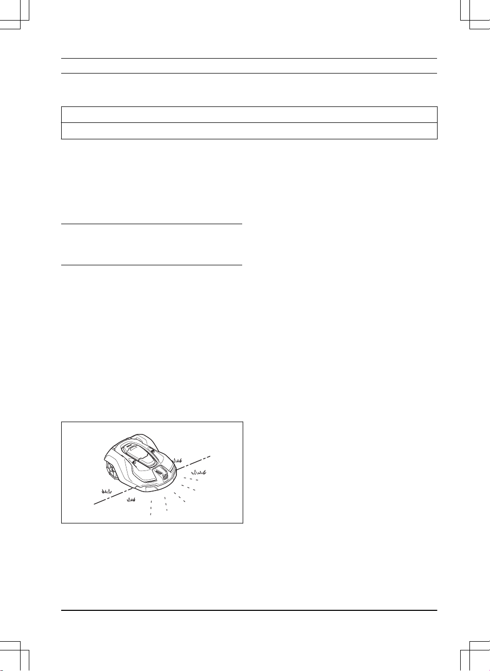
The product is a robotic lawn mower. The product
has a battery power source and cuts the grass
automatically. It continuously alternates between
mowing and charging. The movement pattern is
random, which means that the lawn is mowed
evenly and with less wear. The boundary wire
and the guide wire controls the movement of the
product within the work area. Sensors in the
product senses when it is approaching the
boundary wire. The front of the product always
passes the boundary wire by a specific distance
before the product turns around. When the
product hits an obstacle or approaches the
boundary wire the product selects a new
direction.
The operator selects the operation settings with
the keys on the keypad. The display shows the
selected and possible operation settings, and the
operation mode of the product.
1.1.2.1 Mowing technique
The product is emission free, easy to use and
saves energy. The frequent cutting technique
improves the grass quality and decreases the
use of fertilizers. Collection of grass is not
necessary.
1.1.2.2 Find the charging station
The product operates until the battery state of
charge is low. Then it follows the guide wire to
the charging station. The guide wire is laid from
the charging station towards, for instance, a
remote part of the work area or through a narrow
passage. The guide wire is connected with the
boundary wire and makes it much easier and
faster for the product to find the charging station.
1.1.2.3 Automower® Connect
Automower® Connect is a mobile application that
makes it possible to select the operation settings
remotely. Refer to
Automower® Connect app on
page 25
.
1201 - 004 - 25.03.2020 Introduction - 3
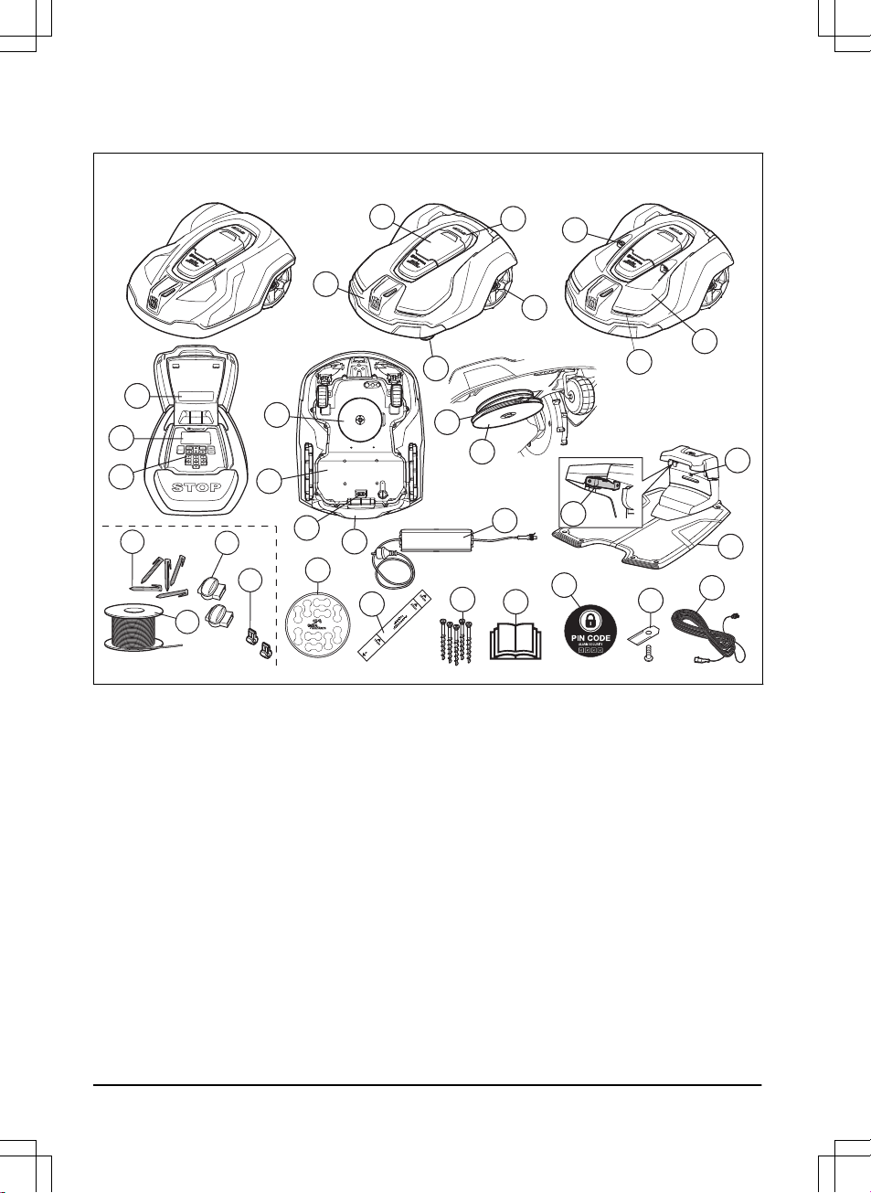
1.2 Product overview
Automower 420/440 Automower 430X Automower 450X
23
22
28
24
25
27
26
21
31
32
30
29
4
5
2
3
1
19
20
9
11
10
12
13
14
15
16
17
6
7
8
18
The numbers in the figure represent:
1. Body
2. Hatch to display and keypad
3. Stop button
4. Front wheels
5. Rear wheels
6. Ultrasonic sensors
7. Headlights
8. Replaceable cover
9. Rating plate (incl. product identification
code)
10. Display
11. Keypad
12. Cutting system
13. Chassis box with electronics, battery and
motors
14. Main switch
15. Handle
16. Blade disc
17. Skid plate
18. Contact plates
19. LED for operation check of the charging
station and boundary wire
20. Charging station
21. Power supply (the appearance may differ
depending on market)
22. Cable markers
23. Measurement gauge when installing the
boundary wire (the measurement gauge is
broken loose from the box)
24. Screws for securing the charging station
25. Operator’s Manual and Quick Guide
26. Alarm decal
27. Extra blades
28. Low voltage cable
4 - Introduction 1201 - 004 - 25.03.2020
29. Couplers for the loop wire
1
30. Loop wire for boundary loop and guide wire
2
31. Stakes
3
32. Connectors for the loop wire
4
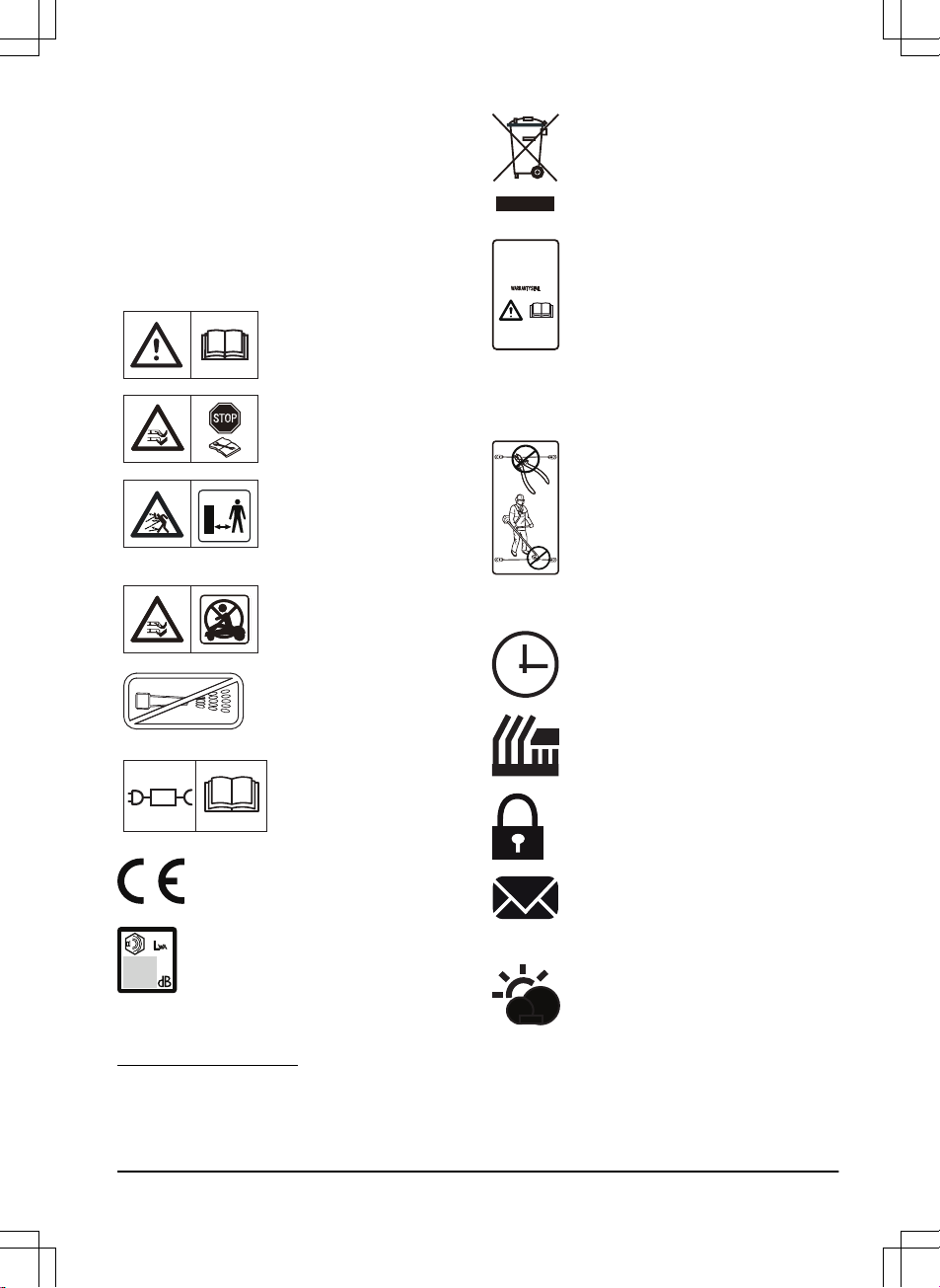
1.3 Symbols on the product
These symbols can be found on the product.
Study them carefully.
WARNING: Read the
user instructions before
operating the product.
WARNING: Disable the
product before working on
or lifting the product.
WARNING: Keep a safe
distance from the product
when operating. Keep
your hands and feet away
from the rotating blades.
WARNING: Do not ride
on the product. Never put
your hands or feet close
to or under the product.
Never use a high-pressure washer or even running water to clean the
product.
Use a detachable power
supply as defined on the
rating label next to the
symbol.
This product conforms to the
applicable EC Directives.
Noise emission to surroundings. The
product’s emissions are set out in
Technical data on page 60
and on the
rating plate.
It is not permitted to dispose this
product as normal household waste.
Ensure that the product is recycled in
accordance with local legal
requirements.
The chassis contains components
which are sensitive to electrostatic
discharge (ESD). The chassis must
also be resealed in a professional
manner. For these reasons the chassis
shall only be opened by authorized
service technicians. A broken seal can
result in the entire or parts of the
guarantee no longer being valid.
The low voltage cable must not be
shortened, extended or spliced.
Do not use a trimmer nearby the low
voltage cable. Be careful when
trimming edges where the cables are
placed.
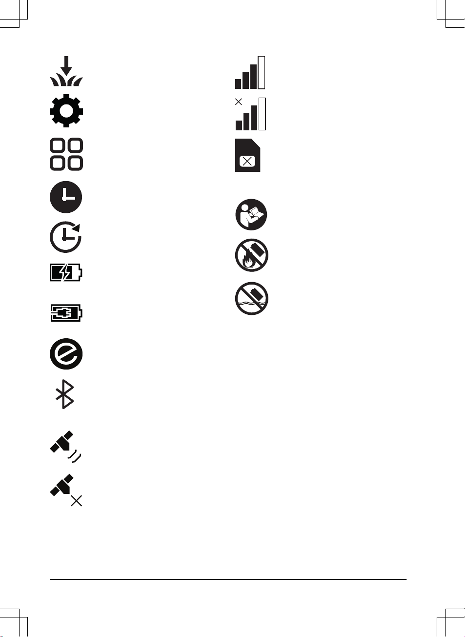
1.4 Symbols on the display
The schedule function controls when
the product cuts the lawn.
The cutting height function sets the
cutting height of the product.
The security function lets the operator
select between 3 security levels.
The messages function shows error
messages and possible cause for the
problems.
The weather timer function
automatically adapts the cutting
intervals to the grass growth.
1
Is a part of the Installation kit which is purchased separately.
2
Is a part of the Installation kit which is purchased separately.
3
Is a part of the Installation kit which is purchased separately.
4
Is a part of the Installation kit which is purchased separately.
1201 - 004 - 25.03.2020
Introduction - 5
The installation function for manual
settings for the installation.
The settings function is where the
general settings for the products are
set.
The accessories function is where all
settings for the accessories for the
product are set.
The product will not cut the grass do to
the schedule function.
The product overrides the schedule
function.
The battery indicator shows the charge
level of the battery. When the product
charges the symbol flashes.
The product is put in the charging
station but do not charge the battery.
The product is set in ECO-mode.
For Automower® Connect and
Connect@Home. Bluetooth® wireless
communication with your mobile
device.
The GPS-supported navigation is
active. Flashes as it collects GPS
information. Automower® 430X/450X.
The GPS-supported navigation is not
active. Automower® 430X/450X.
The signal strength of the GPRS
reception.
Problem with the connection to the
Internet server.
Problem with the SIM card or the
module.
1.5 Symbols on the battery
Read the user instructions.
Do not discard the battery into fire and
do not expose the battery to a heat
source.
Do not immerse the battery into water.
1.6 General manual instructions
The following system is used in the Operator’s
Manual to make it easier to use:
• Text written in
italics
is a text that is shown
in the display or is a reference to another
section in the Operator’s Manual.
• Text written in bold is one of the buttons on
the product.
• Text written in
UPPERCASE
and
italics
refer
to the different operating modes available in
the product.
6
- Introduction
1201 - 004 - 25.03.2020
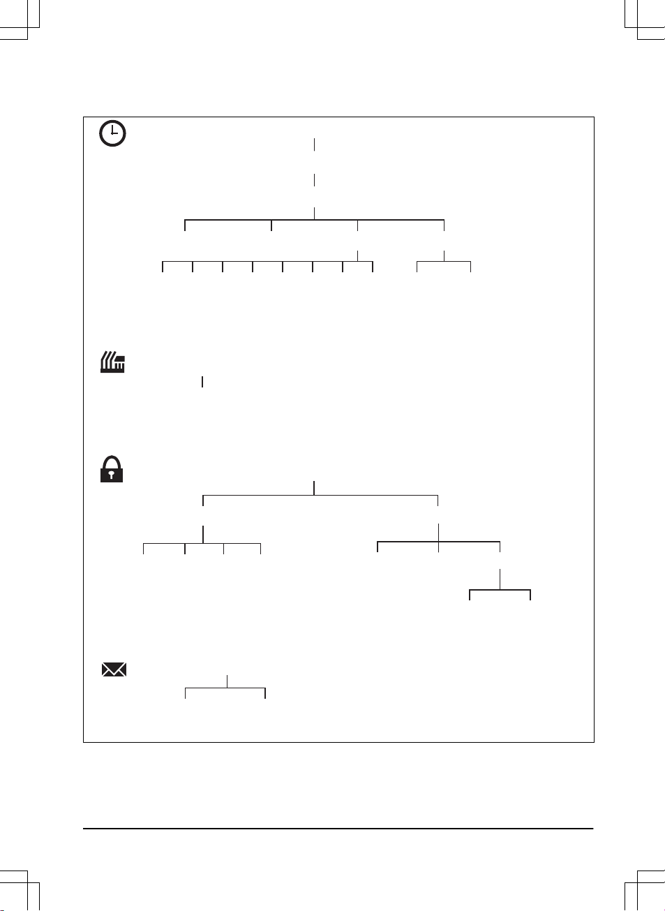
1.7 Menu structure overview 1
Security
Low Medium High Custom
Duration
Duration
of alarm
Duration
of time lock
Change
PIN code
New loop
signal
Security level
Fault
messages
Info
messages
Messages
Advanced
Schedule
Overview (per day)
Overview Schedule settings
Cutting height
Cutting height
Period 1 Period 2 Copy to
Su Current
day
All weekSaFrThWeTuMoAll
days
Reset
1201 - 004 - 25.03.2020 Introduction - 7
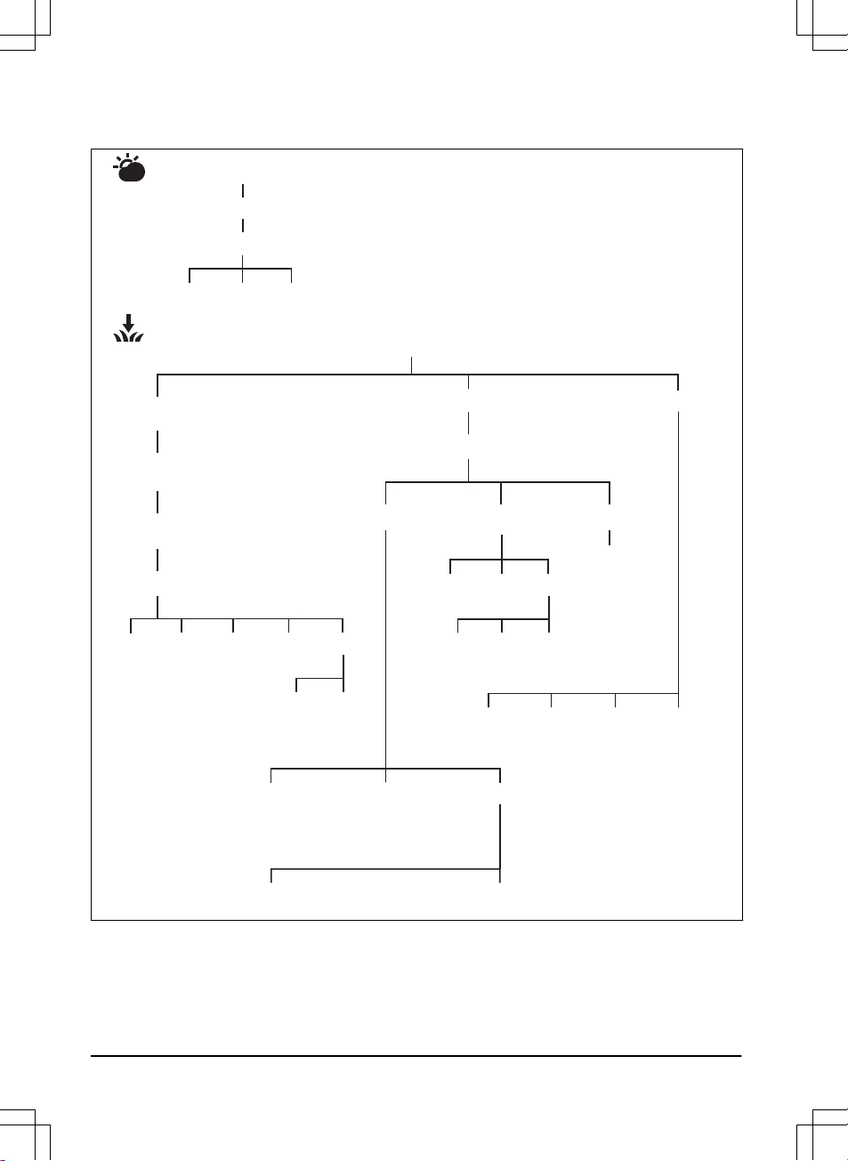
1.8 Menu structure overview 2
Use
Low Medium High
Cutting time
Weather timer
Installation
Lawn
coverage
GPS Auto
430X/450X
Overview of
lawn coverage
Area 1-5
Find charging station
Overview of search method
Guide
Delay time
Test
Reset
Test
left
Test
right
Reset
Disable
Delay time
More
Disable
More
Boundary
Charger
Charging
station range
How?
How
often?
How
far?
Disable
ResetTest
More
Exit
angles
Corridor
width
Reversing
distance
Drive past
wire
Advanced
8 - Introduction 1201 - 004 - 25.03.2020
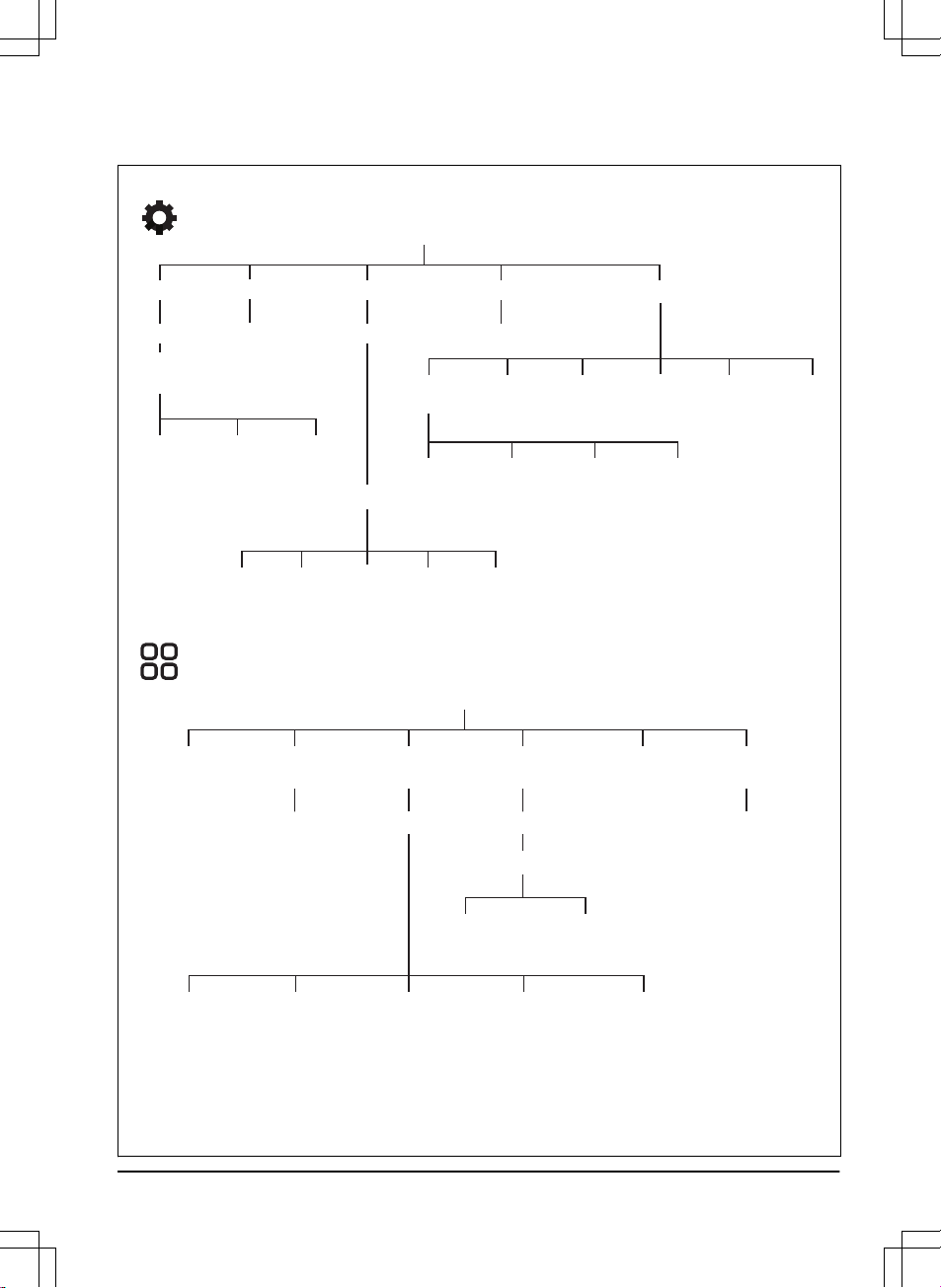
1.9 Menu structure overview 3
Settings
ECO mode
Use
Profiles
Select Rename
Save
Profile A,
B or C
Time &
date
Set time Set date Time format
Date format
Language
Country &
Timezone
Reset all
user setting
About
LowLow-
High High+Medium
Intensity
Spiral cutting General
Use
Use
Headlights
(430X/450X)
Ultrasonic
(450X)
Accessories
Automower
Connect
Mower
house
Information
Slope control
Use
Connect@Home
(420/440)
Pairing Use Aviod collision with
mower house
Pairing Geofence
Communication Network Reset
Use
Headlight
Schedule
Flashes when fault
Unit
format
1201 - 004 - 25.03.2020 Introduction - 9
1.10 Display
The display on the product shows information
and settings of the product.
To access the display, push the STOP button.
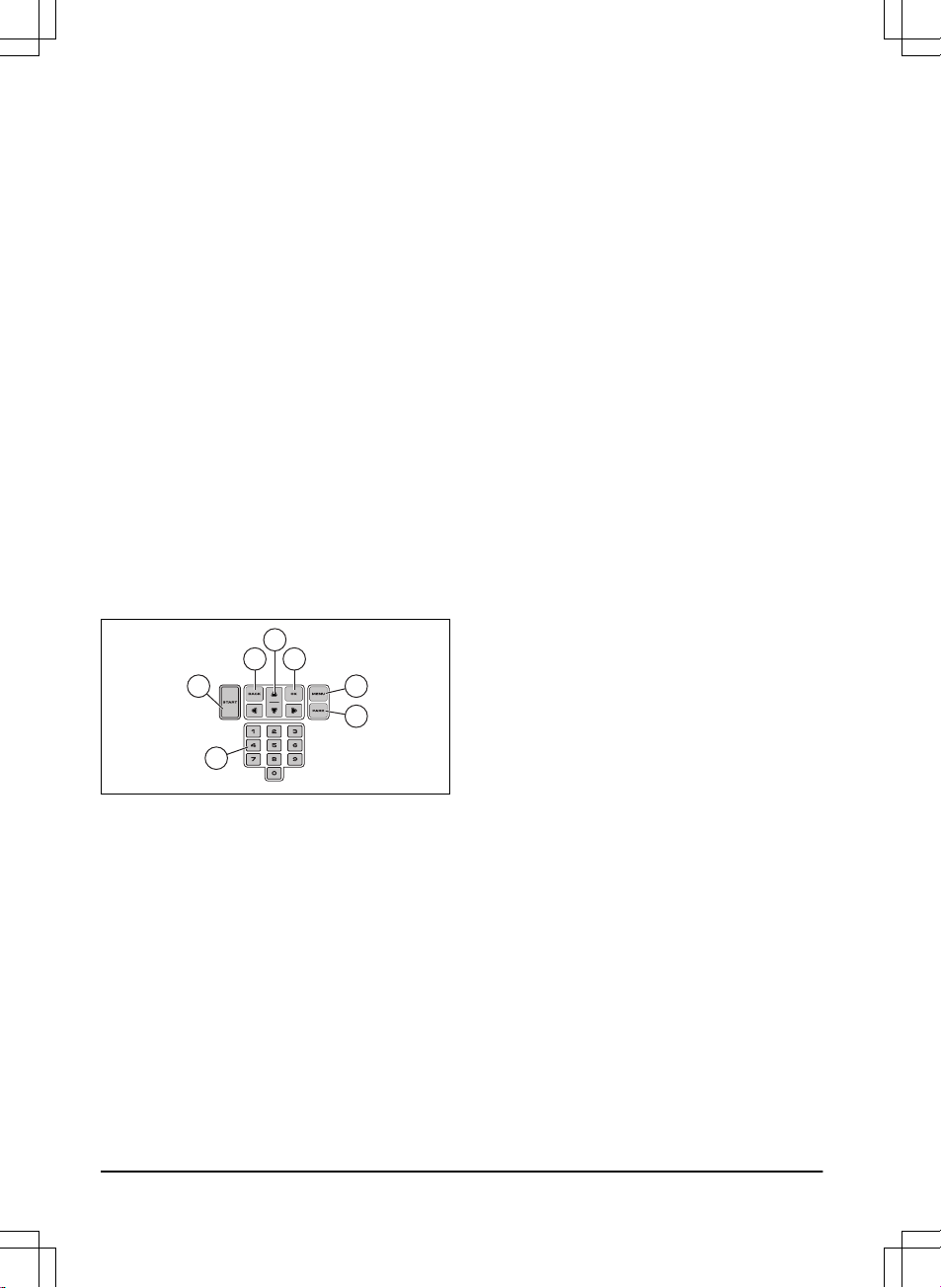
1.11 Keypad
Use the keypad on the product to navigate in the
menu. To access the keypad, push the STOP
button.
• Use the START button (A) to start the
operation of the product.
• Use the BACK button (B) to move up in the
menu lists.
• Use the arrow buttons (C) to navigate in the
menu.
• Use the OK button (D) to confirm the
settings you select in the menus.
• Use the MENU button (E) to go to the main
menu.
• Use the PARK button (F) to send the
product to the charging station.
• Use the number buttons (G) to enter PIN
code, time and date.
A E
F
B D
C
G
10 - Introduction 1201 - 004 - 25.03.2020

2 Safety
2.1 Safety information
2.1.1 IMPORTANT. READ CAREFULLY
BEFORE USE. KEEP FOR FUTURE
REFERENCE
The operator is responsible for accidents or hazards occurring to
other people or property.
This appliance is not intended for use by persons (including
children) with reduced physical, sensory or mental capabilities (that
could affect a safe handling of the product), or lack of experience
and knowledge, unless they have been given supervision or
instruction concerning use of the appliance by a person
responsible for their safety.
This appliance can be used by children aged from 8 years and
above and persons with reduced physical, sensory or mental
capabilities or lack of experience and knowledge if they have been
given supervision or instruction concerning use of the appliance in
a safe way and understand the hazards involved. Local regulations
may restrict the age of the operator. Cleaning and maintenance
shall not be made by children without supervision.
Never connect the power supply to an outlet if the plug or cord is
damaged. Worn or damaged cord increase the risk of electric
shock.
Only charge the battery in the included charging station. Incorrect
use may result in electric shock, overheating or leaking of
corrosive liquid from the battery. In the event of leakage of
electrolyte, flush with water/neutralizing agent. Seek medical help if
it comes in contact with the eyes.
Use only original batteries recommended by the manufacturer.
Product safety cannot be guaranteed with other than original
batteries. Do not use non-rechargeable batteries.
1201 - 004 - 25.03.2020
Safety - 11
The appliance must be disconnected from the supply mains when
removing the battery.
WARNING: The product
can be dangerous if used
incorrectly.
WARNING: Do not use
the product when
persons, especially
children, or animals are
in the work area.
WARNING: Keep your
hands and feet away
from the rotating blades.
Never put your hands or
feet close to or under the
product when the motor
is running.
WARNING: In the event
of an injury or accident
seek medical help.
2.2 Safety definitions
Warnings, cautions and notes are used to point
out specially important parts of the manual.
WARNING:
Used if there is a risk of
injury or death for the operator or
bystanders if the instructions in the
manual are not obeyed.
CAUTION: Used if there is a risk of
damage to the product, other materials
or the adjacent area if the instructions
in the manual are not obeyed.
Note: Used to give more information that is
necessary in a given situation.
2.3 Safety instructions for operation
2.3.1 Use
• The product may only be used with the
equipment recommended by the
manufacturer. All other types of use are
incorrect. The manufacturer’s instructions
with regard to operation/maintenance must
be followed precisely.
• Warning signs shall be placed around the
work area of the product if it is used in public
areas. The signs shall have the following
text: Warning! Automatic lawnmower! Keep
away from the machine! Supervise children!
Warning!
Automatic lawnmower!
Keep away from the machine!
Supervise children!
Warning!
Automatic lawnmower!
Keep away from the machine!
Supervise children!
• Use the operating mode
Park
or switch off
the product when persons, especially
children, or animals, are in the work area. It
is recommended to program the product for
use during hours when the area is free from
activity, e.g. at night. Refer to
Schedule on
page 26
. Consider that certain animals,
e.g. hedgehogs, are active at night. They
can potentially be harmed by the product.
12
- Safety
1201 - 004 - 25.03.2020
• The product may only be operated,
maintained and repaired by persons that are
fully conversant with its special
characteristics and safety regulations.
Please read the Operator’s Manual carefully
and make sure you understand the
instructions before using the product.
• It is not permitted to modify the original
design of the product. All modifications are
made at your own risk.
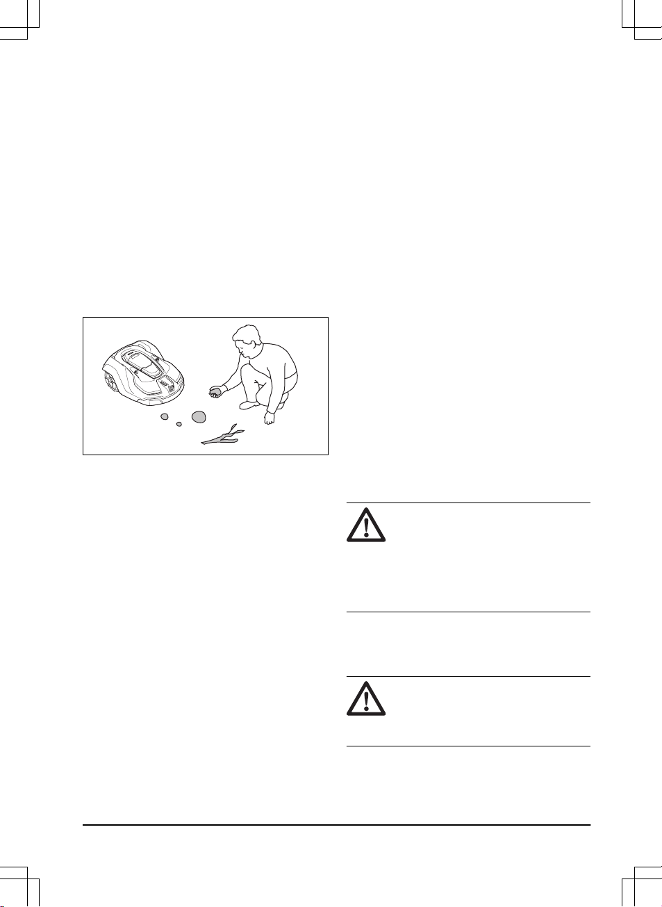
• Check that there are no foreign objects such
as stones, branches, tools or toys on the
lawn. If the blades hit foreign objects the
blades can be damaged. Always switch off
the product with the main switch before
clearing a blockage. Inspect the product for
damage before staring the product again.
• If the product starts to vibrate abnormally,
switch off the product with the main switch.
Examine the product for damages before
you start the product again.
• Start the product according to the
instructions. When the product is switched
on, make sure to keep your hands and feet
away from the rotating blades. Never put
your hands and feet under the product.
• Never touch moving hazardous parts, such
as the blade disc, before it has come to a
complete stop.
• Never lift up the product or carry it around
when it is switched on.
• Do not let persons who do not know how the
product works and behaves use it.
• The product must never be allowed to
collide with persons or other living creatures.
If a person or other living creature comes in
the product’s way it shall be stopped
immediately. Refer to
To stop the product on
page 40
.
• Do not put anything on top of the product or
its charging station.
• Do not allow the product to be used with a
defective guard, blade disc or body. Neither
should it be used with defective blades,
screws, nuts or cables. Never connect a
damaged cable, or touch a damaged cable
before it is disconnected from the supply.
• Do not use the product if the Main switch
does not work.
• Always switch off the product using the Main
switch when the product is not in use. The
product can only start when the Main switch
has been switched on and the correct PIN
code has been entered.
• Husqvarna® does not guarantee full
compatibility between the product and other
types of wireless systems such as remote
controls, radio transmitters, hearing loops,
underground electric animal fencing or
similar.
• Metal objects in the ground (for example
reinforced concrete or anti-mole nets) can
result in a stoppage. The metal objects can
cause interference with the loop signal
which then can lead to a stoppage.
• Operation and storage temperature is 0-50
°C / 32-122 °F. Temperature range for
charging is 0-45 °C / 32-113 °F. Too high
temperatures might cause damage to the
product.
2.3.2 Battery safety
WARNING:
Lithium-ion batteries can
explode or cause fire if disassembled,
short-circuited, exposed to water, fire,
or high temperatures. Handle carefully,
do not dismantle, open the battery or
use any type of electrical/mechanical
abuse. Avoid storage in direct sunlight.
For more information about the battery, refer to
Battery on page 43
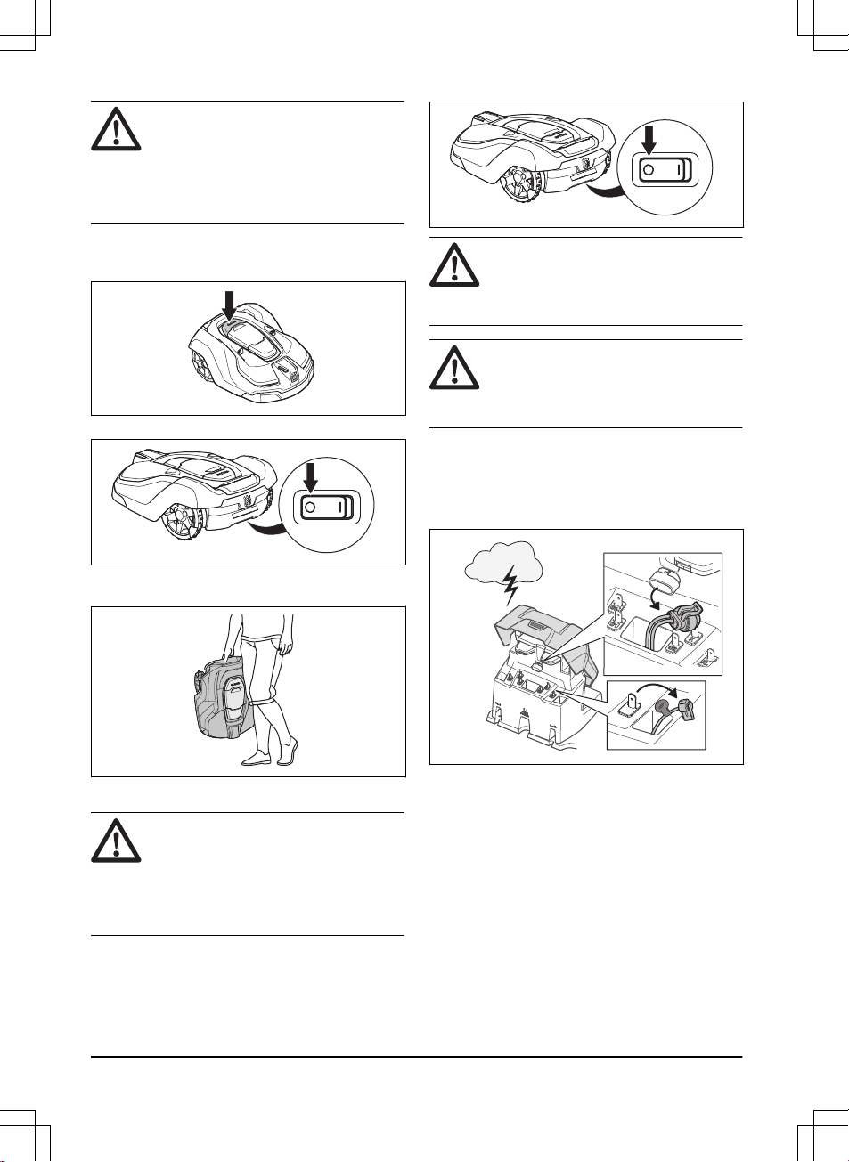
2.3.3 How to lift and move the product
WARNING:
The product must be
switched off before lifting it. The
product is disabled when the Main
switch is in position 0.
1201 - 004 - 25.03.2020
Safety - 13
CAUTION: Do not lift the product when
it is parked in the charging station. It
can damage the charging station
and/or the product. Push STOP and
pull the product out of the charging
station before lifting it.
To safely move from or within the work area:
1. Push the STOP button to stop the product.
2. Set the main switch in position 0.
3. Carry the product by the handle with the
blade disc away from the body.
2.3.4 Maintenance
WARNING:
The product must be
switched off before any maintenance is
done. Use the plug to disconnect the
charging station before any cleaning or
maintenance of the charging station or
the loop wire.
WARNING: Use the plug to disconnect
the charging station before any
cleaning or maintenance of the
charging station or the loop wire.
CAUTION: Never use a high-pressure
washer or even running water to clean
the product. Never use solvents for
cleaning.
Inspect the product weekly and replace any
damaged or worn parts. Refer to
Maintenance on
page 42
.
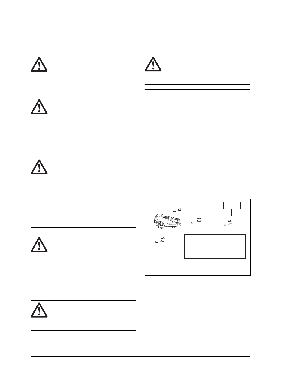
2.3.5 In the event of a thunderstorm
To reduce the risk of damage to electrical
components in the product and the charging
station, we recommend that all connections to the
charging station are disconnected (power supply,
boundary wire and guide wire) if there is a risk of
a thunderstorm.
1. Mark the wires to simplify reconnecting. The
charging station’s connections are marked
AR, AL and G1/G2/G3.
2. Disconnect all connected wires and the
power supply.
3. Connect all the wires and the power supply
if there is no longer a risk of thunder. It is
14
- Safety
1201 - 004 - 25.03.2020

important that each wire is connected to the
right place.
1201 - 004 - 25.03.2020 Safety - 15

3 Installation
3.1 Introduction - Installation
WARNING: Read and understand the
safety chapter before you install the
product.
CAUTION: Use original spare parts
and installation material.
Note: Refer to www.husqvarna.com for more
information about installation.
3.2 Main components for installation
The installation involves the following
components:
• A robotic lawn mower that mows the lawn
automatically.
• A charging station, which has 3 functions:
• To send control signals along the
boundary wire.
• To send control signals along the guide
wire so that the product can follow the
guide to specific remote areas in the
garden and can find its way back to the
charging station.
• To charge the product.
• A power supply, which is connected to the
charging station and a 100-240V wall
socket.
• Loop wire, which is laid around the work
area and around objects and plants that the
product must not run into. The loop wire is
used both as boundary wire and guide wire.
3.3 General preparations
CAUTION:
Holes with water in the
lawn can cause damage to the
product.
Note: Read through the Installation chapter
before beginning the installation. How the
installation is done affects how the product
performs. It is therefore important to plan the
installation carefully.
• Make a blueprint of the work area and
include all obstacles. This makes it easier to
see the ideal positions for the charging
station, the boundary wire and the guide
wire.
• Make a mark on the blueprint where to put
the charging station, the boundary wire and
the guide wire.
• Make a mark on the blueprint where the
guide wire connects to the boundary wire.
Refer to
To install the guide wire on page
23
.
• Fill in holes in the lawn.
• Cut the grass before you install the product.
Make sure that the grass is maximum 10
cm / 3.9 in.
Note: The first weeks after installation the
perceived sound level when cutting the grass
may be higher than expected. When the product
has cut the grass for some time, the perceived
sound level is much lower.
3.4 Before the installation of the wires
You can select to attach the wires with stakes or
bury them. You can use the 2 procedures for the
same work area.
• Bury the boundary wire or the guide wire if
you are going to use a dethatcher on the
work area. If not, attach the boundary wire
or guide wire with stakes.
3.4.1 To examine where to put the charging
station
• Keep a minimum 3 m / 10 ft. of free space in
front of the charging station. Refer to
To
examine where to put the guide wire on
page 20
.
• Keep a minimum of 1.5 m / 5 ft. of free
space to the right and left of the center of
the charging station.
• Put the charging station near a power outlet.
• Put the charging station on a level surface.
16
- Installation
1201 - 004 - 25.03.2020
max. 5 cm / 2"
max. 5 cm / 2"
• Put the charging station in the lower section
of the work area.
• Put the charging station in an area with
protection from the sun.
• If the charging station is installed on an
island, make sure to connect the guide wire
to the island. Refer to
To make an island on
page 19
.
3.4.2 To examine where to put the power
supply
WARNING:
Do not cut or extend the
low-voltage cable. There is a risk of
electrical shock.
CAUTION: Make sure that the blades
on the product do not cut the lowvoltage cable.
WARNING: The power supply cable
and extension cable must be outside
the work area to avoid damage to the
cables.
CAUTION: Do not put the low-voltage
cable in a coil or below the charging
station plate. The coil causes
interference with the signal from the
charging station.
• Put the power supply in an area with a roof
and protection from the sun and rain.
• Put the power supply in an area with good
airflow.
• Use a residual-current device (RCD) when
you connect the power supply to the power
outlet.
Low-voltage cables of different lengths are
available as accessories.
3.4.3 To examine where to put the
boundary wire
CAUTION: If the work area is adjacent
to water bodies, slopes, precipices or a
public road, the boundary wire must
have a protective wall. The wall must
be minimum 15 cm / 6 in. in height.
CAUTION: Do not let the product
operate on gravel.
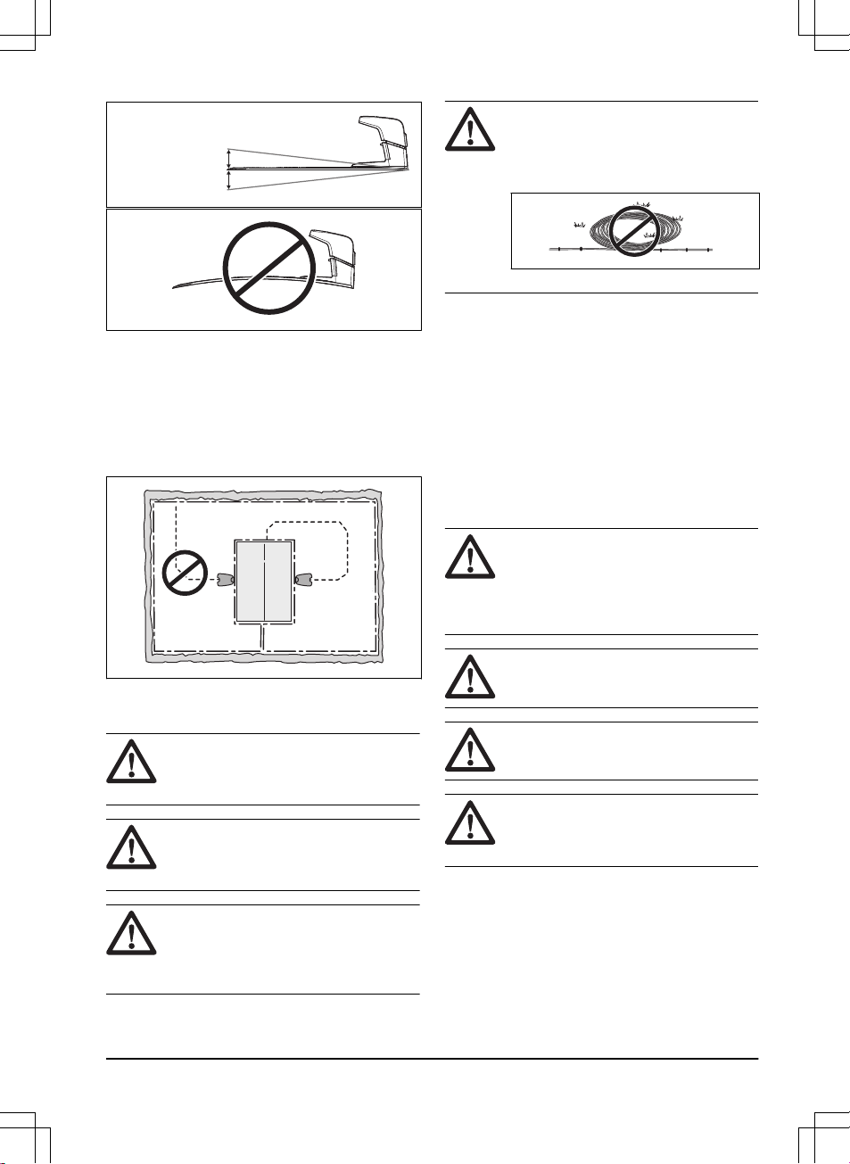
CAUTION: Do not make sharp bends
when you install the boundary wire.
CAUTION: For careful operation
without noise, isolate all obstacles
such as trees, roots and stones.
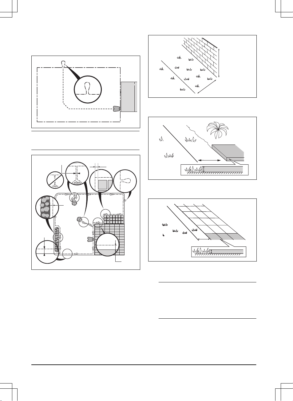
The boundary wire should be put as a loop
around the work area. Sensors in the product
senses when the product approaches the
boundary wire, and the product selects another
direction.
To make the connection easier between the
guide wire and the boundary wire, it is
1201 - 004 - 25.03.2020
Installation - 17
recommended to make an eyelet where the guide
wire will be connected. Make the eyelet with
approximately 20 cm / 8 in. of the boundary wire.
Note: Make a blueprint of the work area before
you install the boundary wire and guide wire.
D
E
B
C
F
A
• Put the boundary wire around all of the work
area (A). Adapt the distance between the
boundary wire and obstacles.
• Put the boundary wire 35 cm / 14 in. (B)
from an obstacle that is more than 5 cm / 2
in. high.
35 cm /14
"
> 5 cm / 2
"
• Put the boundary wire 30 cm / 12 in. (C)
from an obstacle that is 1-5 cm / 0.4-2 in.
high.
1-5 cm / 0.4 - 2"
30 cm / 12"
• Put the boundary wire 10 cm / 4 in. (D) from
an obstacle that is less than 1 cm / 0.4 in.
high.
10 cm / 4"
max 1 cm / 0.4"
• If you have a paving stone path that is in
level with the lawn, put the boundary wire
below the paving stone.
Note:
If the paving stone is minimum 30 cm /
12 in. wide, use the factory setting for the
Drive Past Wire
function to cut all the grass
adjacent to the paving stone. Refer to
To set
the Drive Past Wire function on page 33
.
• If you make an island, put the boundary wire
that runs to and from the island near
together (E). Put the wires in the same
stake. Refer to
To make an island on page
19
.
18
- Installation
1201 - 004 - 25.03.2020
• Make an eyelet (F) where the guide wire is
to be connected to the boundary wire.
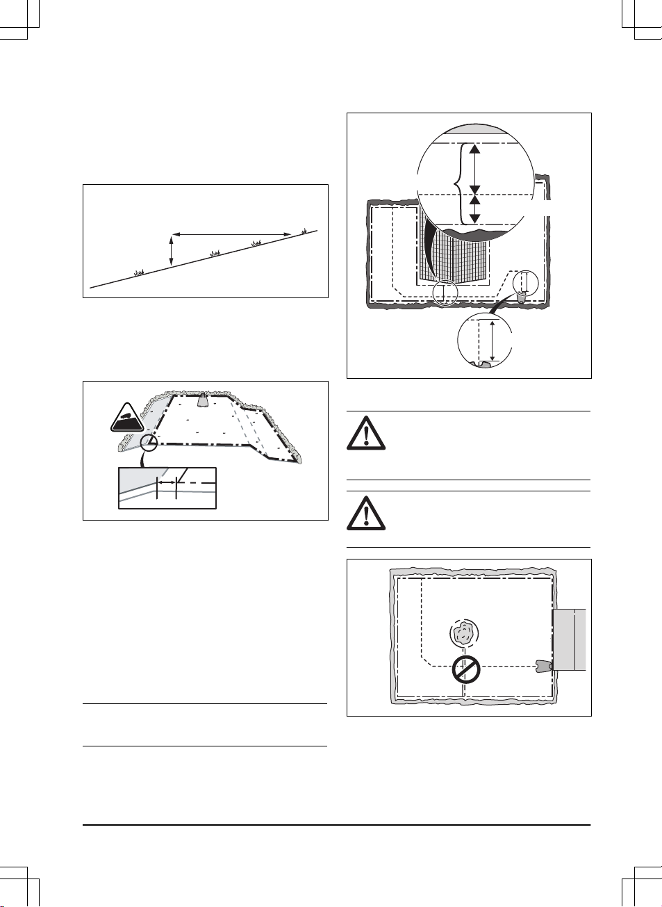
3.4.3.1 To put the boundary wire in a slope
The product can operate in 45% slopes. Slopes
that are too steep must be isolated with the
boundary wire. The gradient (%) is calculated as
height per m. Example: 10 cm / 100 cm = 10%.
10 cm/ 4"
100 cm/ 40"
10%
• For slopes steeper than 45% inside the work
area, isolate the slope with boundary wire.
• For slopes steeper than 15% along the outer
edge of the lawn, put the boundary wire 20
cm / 8 in. (A) from the edge.
A
>10%
0-25%
• For slopes adjacent to a public road, put a
fence or a protective wall along the outer
edge of the slope.
• Make sure that there is as much free area as
possible to the left of the guide wire. The
product moves on the left side of the guide
wire, when you face the charging station.
3.4.3.2 Passages
A passage is a section that has boundary wire on
each side and that connects 2 work areas. The
passage must be a minimum of 60 cm / 24 in.
between the boundary wire.
Note:
If a passage is less than 2 m / 6.5 ft. wide,
install a guide wire through the passage.
The product always runs to the left of the guide
wire as seen facing the charging station. Make
sure that the guide wire has as much free area as
possible to the left of the guide wire.
>2 m / 6.5 ft
Max.
distance
>60 cm / 24"
>30 cm / 12"
3.4.3.3 To make an island
CAUTION: Do not put a section of
boundary wire across the other. The
sections of boundary wire must be
parallel.
CAUTION: Do not put the guide wire
across the boundary wire, for example
a boundary wire that goes to an island.
Some obstacles can withstand a collision, for
example, trees or bushes taller than 15 cm / 6 in.
The product will collide and then turn around with
this type of obstacle. However, obstacles that
slope slightly, for example stones or large trees
1201 - 004 - 25.03.2020
Installation - 19
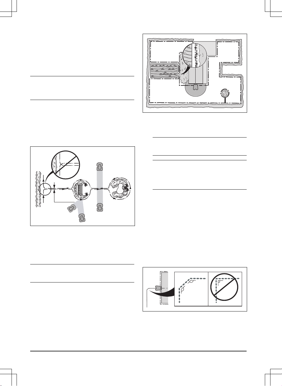
with raised roots, must be isolated or removed.
The product can run onto this kind of obstacle
causing the blades to be damaged. Use the
boundary wire to isolate areas inside the work
area by creating islands. When the boundary
wires to and from the island are put close
together, the product can run over the wire.
Note: To achieve careful and silent operation, it is
recommended to isolate all fixed objects in the
work area.
• Put the boundary wire to and around the
obstacle to make an island.
• Put the 2 sections of boundary wire that run
to and from the obstacle close together
without crossing.
• Put the 2 sections of boundary wire in the
same stake.
0 cm / 0
"
3.4.3.4 To make a secondary area
Make a secondary area (B) if the work area has 2
areas that are not connected with a passage. The
work area with the charging station is the main
area (A).
Note:
The product must be manually moved
between the main area and the secondary area.
B
A
• Put the boundary wire around the secondary
area (B) to make an island. Refer to
To
make an island on page 19
.
Note: The boundary wire must be put as 1
loop around all of the work area (A + B).
Note: When the product cuts grass in the
secondary area, the
Secondary area
mode
must be selected. Refer to
Operating mode
Start on page 39
.
3.4.4 To examine where to put the guide
wire
• Put the guide wire in a line at a minimum of
2 m / 6.5 ft. in front of the charging station.
• Make as much free area as possible to the
left of the guide wire when facing the
charging station. Refer to
Corridor width on
page 32
.
• Put the guide wire minimum 30 cm / 12 in.
from the boundary wire.
• Do not make sharp bends when you install
the guide wire.
135º
135º
90º
• If the work area has a slope, put the guide
wire diagonally across the slope.
20
- Installation
1201 - 004 - 25.03.2020
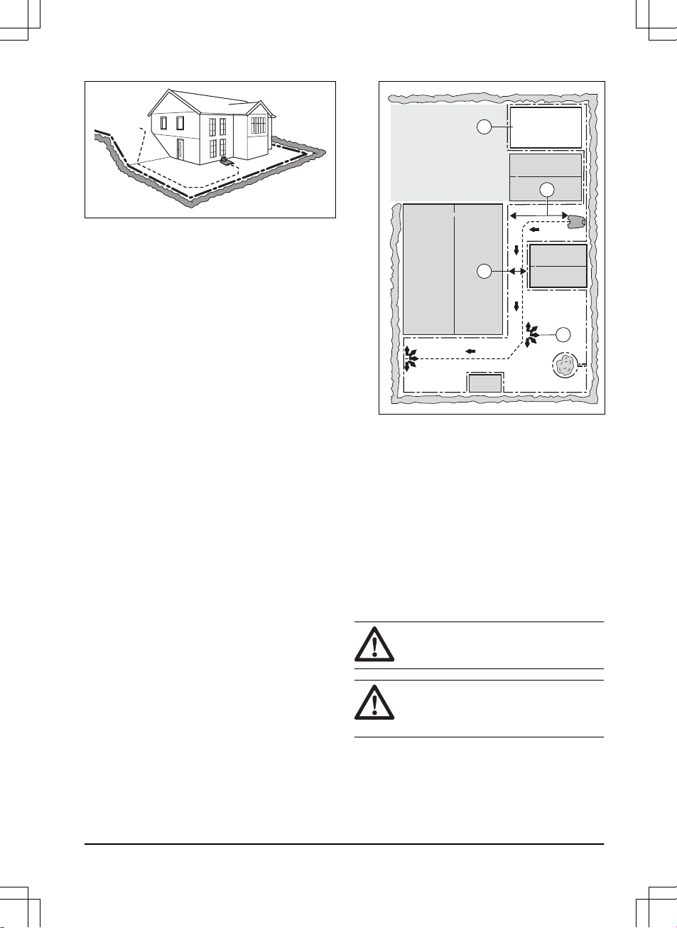
3.4.5 Work area examples
• If the charging station is put in a small area
(A), make sure that the distance to the
boundary wire is at a minimum 3 m / 10 ft. in
front of the charging station.
• If the work area has a passage (B), make
sure that the distance to the boundary wire
is at a minimum 2 m / 6.5 ft. If the passage is
smaller than 2 m / 6.5 ft., install a guide wire
through the passage. Minimum passage
between the boundary wire is 60 cm / 24 in.
• If the work area has areas which are
connected by a narrow passage (B), you
can set the product to first follow and then
leave the guide wire after a certain distance
(C). The settings can be changed in
Lawn
Coverage on page 29
.
• Use the GPS Assisted Navigation that helps
the product select the most optimal
operation. Refer to
To set the GPS Assisted
Navigation on page 30
.
• If the work area includes a secondary area
(D), refer to
To make a secondary area on
page 20
. Put the product in the secondary
area and select
Secondary area mode
.
B
D
A
C
3.5 Installation of the product
3.5.1 Installation tools
• Hammer/plastic mallet: To simplify putting
the stakes into the ground.
• Edge cutter/straight spade: To bury the
boundary wire.
• Combination pliers: For cutting the boundary
wire and pressing the connectors together.
• Adjustable plier: For pressing the couplers
together.
3.5.2 To install the charging station
WARNING: Obey national regulations
about electrical safety.
WARNING: The product is only to be
used with the power supply unit
supplied by Husqvarna.
1201 - 004 - 25.03.2020
Installation - 21
 Loading...