

Husqvarna 305 User Manual

HUSQVARNA AUTOMOWER
305
OPERATOR’S MANUAL
®


TABLE OF CONTENTS
1. Introduction and safety
1.1 Introduction
.....................................................................................
1.2 Symbols on the product
1.3 Symbols in the Operator’s Manual
1.4 Safety instructions
2. Presentation
2.1 What’s what?
2.2 Function
3. Installation
3.1 Preparations
..................................................................................
..............................................................................
.........................................................................................
.....................................................................................
.................................................................................
3.2 Installation of the charging station
3.3 Charging the battery
3.4 Installation of the boundary wire
3.5 Connecting the boundary wire
3.6 Installation of the guide wire
3.7 Checking the installation
3.8 First start-up and calibration
..............................................................
..............................................................
..........................................
........................................................................
.......................................
..................................................................
...........................................
..............................................
..................................................
.........................................................
...................................................
3.9 Test docking with the charging station
....................................................................................................
4. Use
4.1 Charging a discharged battery
4.2 Using the timer
4.3 Starting
4.4 Stopping
4.5 Switching off
............................................................................
...........................................................................................
........................................................................................
................................................................................
4.6 Adjusting the cutting height
5. Control panel
5.1 Operation selection
5.2 Multi-choice buttons
5.3 Numbers
5.4 Main switch
6. Menu functions
6.1 Main menu
6.2 Menu structure
6.3 Timer (1)
6.4 Installation (2)
6.5 Security (3)
6.6 Settings (4)
7. Garden example
8. Maintenance
8.1 Winter storage
8.2 Service
8.3 After winter storage
8.4 Cleaning
................................................................................
....................................................................
...................................................................
........................................................................................
...................................................................................
............................................................................
....................................................................................
.............................................................................
........................................................................................
..............................................................................
...................................................................................
...................................................................................
..........................................................................
..................................................................................
.............................................................................
...........................................................................................
....................................................................
........................................................................................
8.5 Transport and removal
8.6 In the case of thunderstorms
8.7 Blades
8.8 Battery
9. Trouble shooting
9.1 Messages
...........................................................................................
............................................................................................
........................................................................
......................................................................................
9.2 Indicator light on the charging station
9.3 Symptom
.......................................................................................
9.4 Finding breaks in the loop wire
10. Technical data
...........................................................................
11. Environmental information
...............................................
.....................................................
..............................................................
..................................................
.................................
..............................................
..................................................
................................
5
5
6
7
8
10
11
12
15
15
16
20
21
27
28
31
32
33
34
34
35
36
36
36
37
38
39
39
40
40
41
41
42
43
44
47
49
50
53
53
54
54
54
55
55
56
56
58
58
61
62
64
68
68
English - 3

Serial number:
PIN code:
MEMO
Dealer:
Dealer’s telephone
number:
If the mower is unexpectedly stolen, it is important to notify your dealer of this. Provide the serial number of
the mower so that is can be registered as stolen in the central systems at Husqvarna AB. It is an important
step in theft protection procedure which reduces interest in the buying and selling of stolen mowers.
www.automower.com
4 - English
1. INTRODUCTION AND SAFETY
1. Introduction and safety
1.1 Introduction
Congratulations on your choice of an exceptionally
high quality product. To get the best results from your
Husqvarna Automower
function. This Operator's Manual contains important
information about the mower, how it must be installed
and how to use it.
®
requires knowledge of its
As a complement to this Operator's Manual, there is
more information available on the Automower
website, www.automower.com. Here you can find
more help and guidance in its use.
Husqvarna AB has a policy of continuous product
development and therefore reserves the right to
modify the design and appearance and function of
products without prior notice.
The following system is used in the Operator's Manual
to make this easier:
• Text written in italics is a text that is shown on the
mower's display or is a reference to another
section of the Operator's Manual.
• Words written in bold are one of the buttons on
the mower's keypad.
• Words written in UPPERCASE and italics refer to
the position of the main switch and the different
operating modes on the mower.
IMPORTANT INFORMATION
®
www.automower.com
Read through the Operator’s Manual carefully
and understand the content before using
your Automower
WARNING
Automower
incorrectly used.
®
.
®
can be dangerous if
English - 5
.
1. INTRODUCTION AND SAFETY
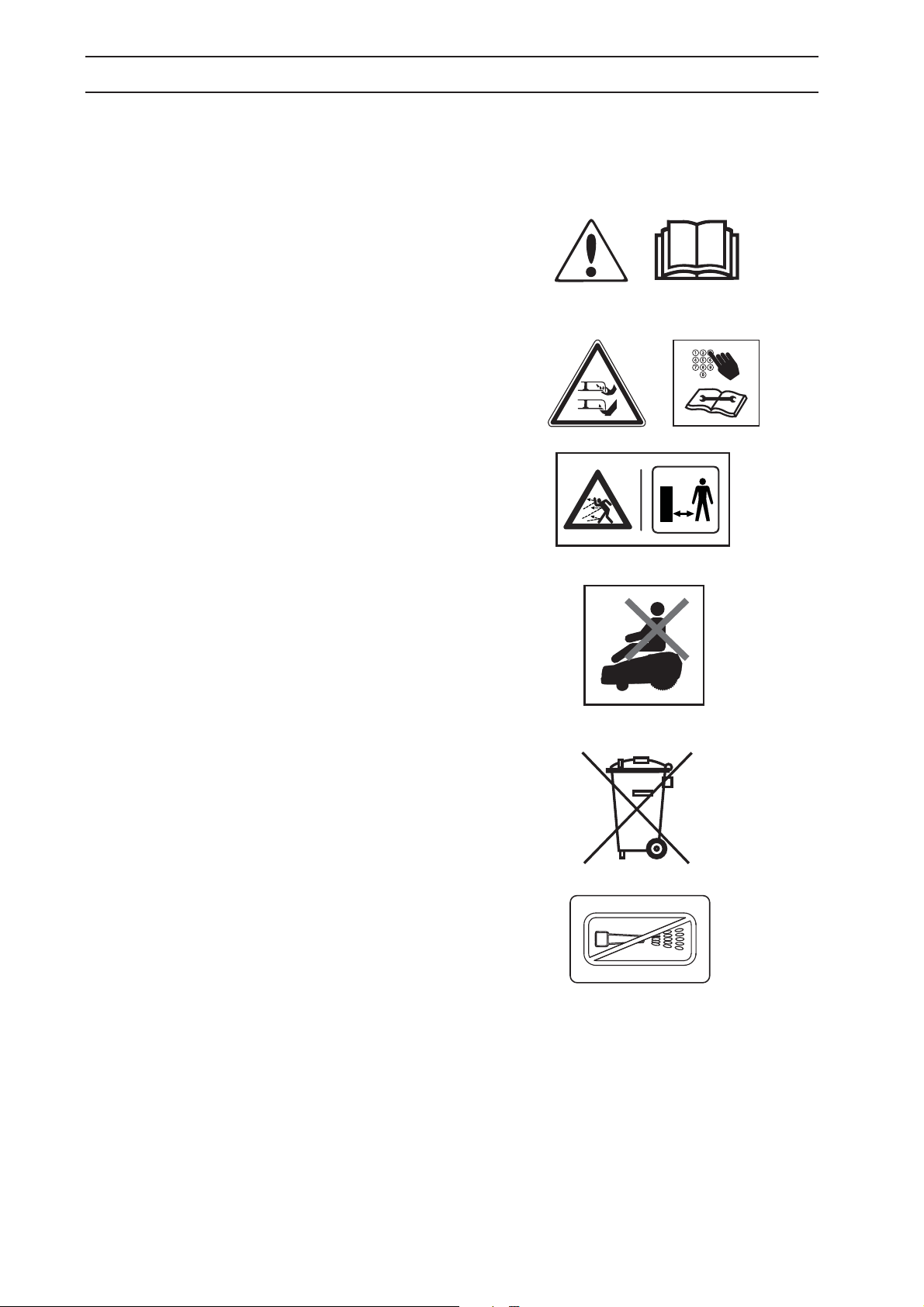
1.2 Symbols on the product
These symbols can be found on the robotic lawn
mower. Study them carefully.
• Read through the Operator’s Manual carefully
and understand the content before using your
Automower
instructions in this Operator’s Manual must be
carefully followed if the mower is to be used
safely and efficiently.
• Automower
is moved to the 1 position and the correct PIN
code has been entered. Inspection and/or
maintenance must be carried out with the main
switch set to 0 .
®
. The warnings and safety
®
can only start when the main switch
• Remain at a safe distance from the Automower
when it is running. Keep your hands and feet
away from the rotating blades. Never place your
hands or feet close to or under the body when
Automower
• Do not ride on Automower
®
is in operation.
®
.
• It is not permitted to dispose of this product as
normal household waste when it has reached the
end of its useful life. Ensure that the product is
recycled in accordance with local legal
requirements.
• Never use a high-pressure washer or even
running water to clean Automower
®
®
Other symbols/decals on the machine refer to
special certification requirements for certain
markets.
6 - English
1. INTRODUCTION AND SAFETY
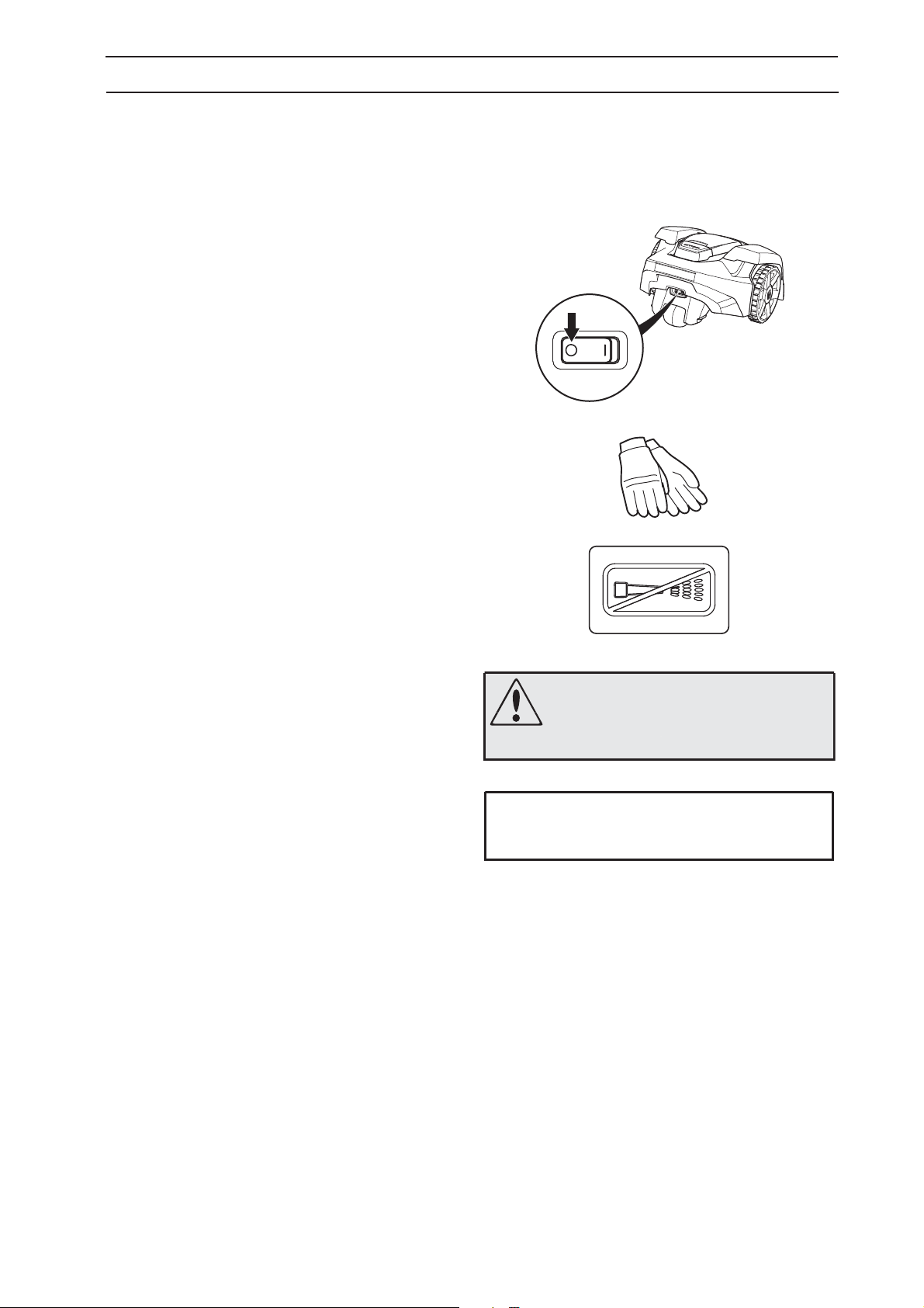
1.3 Symbols in the Operator’s Manual
These symbols can be found in the Operator’s Manual.
Study them carefully.
• Turn the main switch to 0 before carrying out any
inspections and/or maintenance.
• Always wear protective gloves when working
with the mower’s underframe.
• Never use a high-pressure washer or even
running water to clean Automower
• A warning box indicates a risk of personal injury
exist, especially when the stated instructions are
not followed.
• An information box indicates a risk of material
damage exist, especially when the stated
instructions are not followed. The box is also
used where there is a risk of user error.
®
.
WARNING
Xxxxxx xxxxx xxxx xxxx xxxxx xxx.
IMPORTANT INFORMATION
Xxxxxx xxxxx xxxx xxxx xxxxx xxx.
English - 7
1. INTRODUCTION AND SAFETY
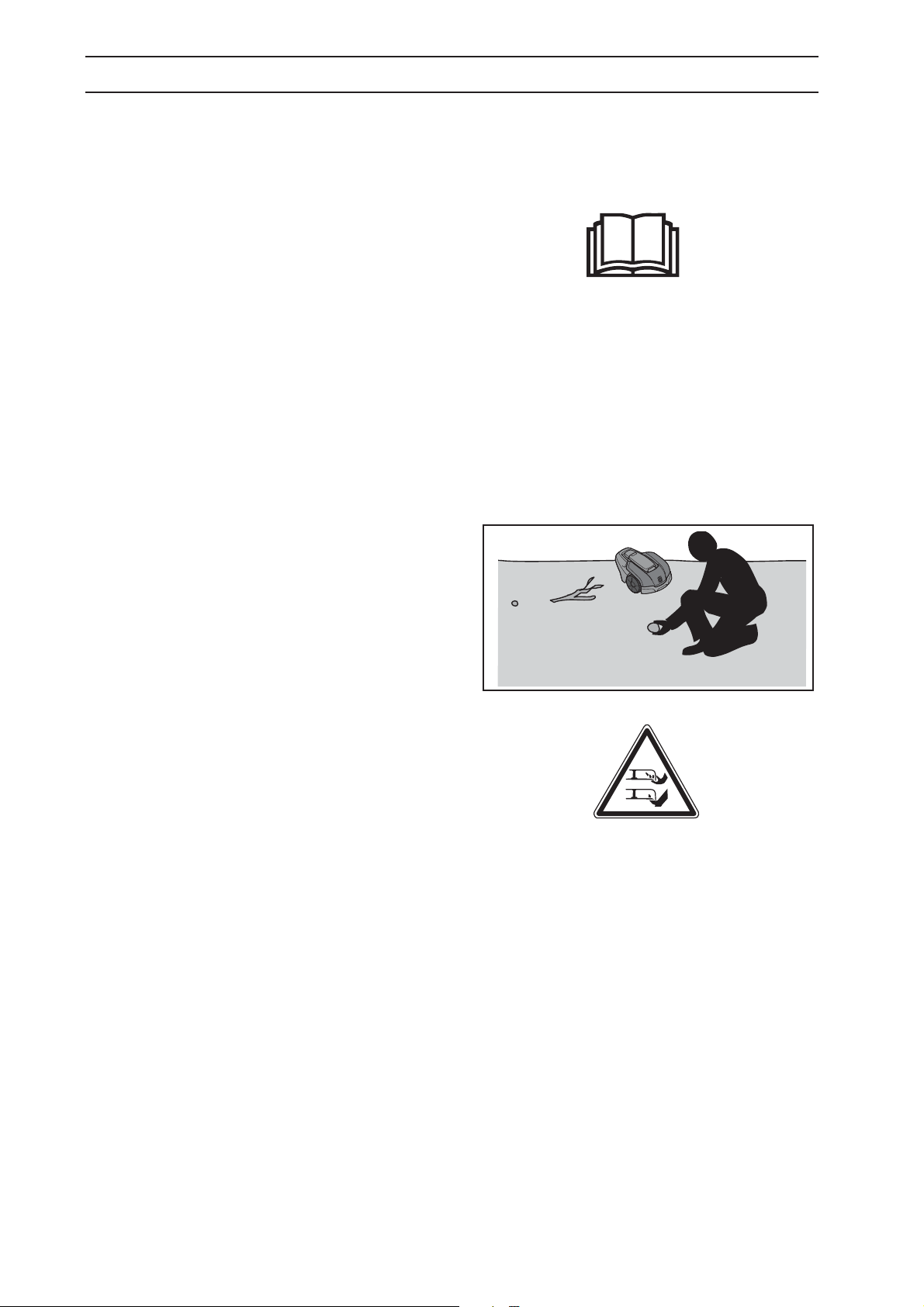
1.4 Safety instructions
Use
• PThis robotic lawn mower is designed to mow
grass in open and level ground areas. It may only
be used with the equipment recommended by
the manufacturer. All other types of use are
incorrect. The manufacturer’s instructions with
regard to operation, maintenance and repair
must be followed precisely.
• The robotic lawn mower may only be operated,
maintained, and repaired by persons that are fully
conversant with its special characteristics and safety
regulations. Please read the Operator’s Manual
carefully and make sure you understand the
instructions before using the robotic lawn mower.
• It is not permitted to modify the original design of
Automower
own risk.
• Check that there are no stones, branches, tools,
toys or other objects on the lawn that can damage
the blades and cause the mower to stop.
Start Automower
When the main switch is in the 1 position make
sure to keep your hands and feet away from the
rotating blades. Never put your hands and feet
under the mower.
• Never lift up Automower
the main switch is in the 1 position.
• Do not let persons who do not know how
Automower
• Never use Automower
children, or pets, are in the immediate vicinity.
• Do not put anything on top of Automower
charging station.
• Do not allow Automower
defective blade disc or body. Neither should it be
used with defective blades, screws, nuts or cables.
• Do not use Automower
not work.
• Always switch off the Automower
switch when the mower is not in use. Automower
can only start when the main switch is set to 1 and
the correct PIN code has been entered.
• Automower
as a sprinkler. In this case use the timer function,
see 6.3 Timer (1) on page 43, so the mower and
sprinkler never run simultaneously.
• Husqvarna AB does not guarantee full
compatibility between Automower
types of wireless systems such as remote
controls, radio transmitters, buried electric animal
fencing or similar.
®
. All modifications are made at your
®
according to the instructions.
®
or carry it around when
®
works and behaves use the mower.
®
if persons, especially
®
or its
®
to be used with a
®
if the main switch does
®
using the main
®
must never be used at the same time
®
and other
®
8 - English
Transport
0
1. INTRODUCTION AND SAFETY
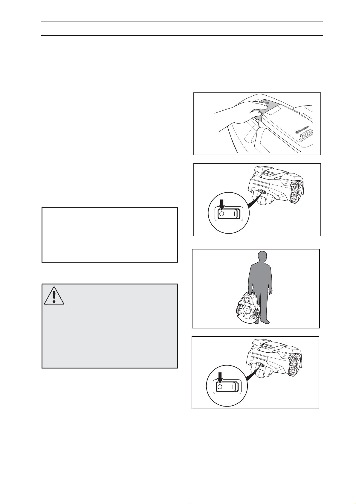
The original packaging should be used when
transporting Automower
To safely move from or within the working area:
1. Press the STOP button to stop the mower. If
security is set to the medium or high level (see
6.5 Security (3) on page 47), the PIN code has to
be entered. The PIN code has four digits and is
chosen when the mower is started for the first
time, see 3.8 First start-up and calibration on
page 32.
2. Set the main switch to position 0.
3. Carry the mower by the handle at the rear under
the mower. Carry the mower with the blade disc
away from the body.
IMPORTANT INFORMATION
Do not lift the mower when it is parked in the
charging station. This may damage the
charging station and/or the mower. Open the
cover and instead first pull the mower out of
the charging station before lifting it.
®
over long distances.
Maintenance
WARNING
When the mower is turned upside
down the main switch must always
be set to the 0 position.
The main switch should be set to the
position during all work on the
mower’s underframe, such as
cleaning or replacing the blades.
• Inspect Automower
damaged or worn parts.
Check especially that the blades and blade disc
are not damaged. Replace all blades and screws
at the same time if necessary so that the rotating
parts are balanced, see 8.7 Blades .
®
each week and replace any
English - 9
2. PRESENTATION
2. Presentation
This chapter contains information that is important to
be aware of when planning the installation.
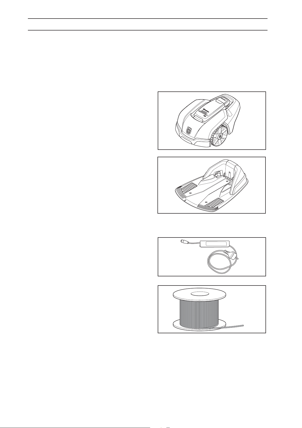
An installation of Husqvarna Automower
main components:
• The Automower
®
is a robotic lawn mower that
mows the lawn by essentially operating in a
random pattern. The mower is powered by a
maintenance-free battery.
®
includes four
®
• Charging station, where your Automower
returns when the charge level in the battery
becomes too low.
The charging station has three functions:
• To send control signals along the boundary
wire.
• Sending control signals in the guide wire so
that Automower
• To charge Automower
®
can find the charging station.
®
battery.
• Transformer, which is connected between the
charging station and a 120V(230V) wall socket.
The transformer is connected to the wall socket
and to the charging station using a 33 ft (10 m)
long low voltage cable. The low voltage cable
must not be shortened or extended.
• Wire, laid in a loop around Automower
®
working
area. The boundary wire is laid around the edges
of the lawn and around objects and plants that
the mower must not run into. The wire is also
used as the guide wire.
10 - English
The wire supplied with the installation is 1300 ft
(150 m) long. If this is not sufficient more wire
can be purchased, with a connector, and spliced
onto the existing wire.
The maximum permitted length for the loop wire is
820 feet (250 m).
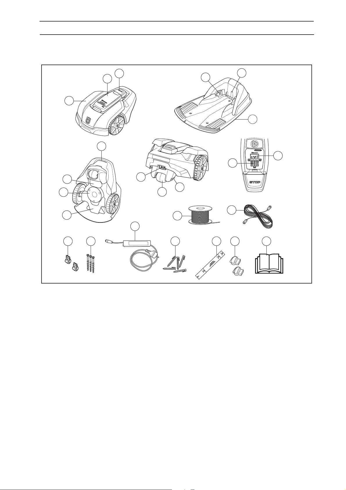
2.1 What’s what?
2. PRESENTATION
9
10
3
2
4
5
1
6
7
15
14
8
11
13
12
17
16
20
19
21 22 23 2418
The numbers in the picture correspond to:
1. Body
2. Cover to display, keypad and cutting height
adjustment
3. Stop button/Lock button for opening the cover
4. Contact strip
5. LED for operation check of the charging station,
boundary wire and guide wire
6. Charging station
7. Handle
8. Battery cover
9. Blade disc
10. Chassis box with electronics, battery and motors
11. Main switch
12. Rear wheel
13. Charging strip
14. Keypad
15. Display
16. Loop wire for boundary wire and guide wire
17. Low voltage cable
18. Connector for the loop wire
19. Nails for securing the charging station
20. Transformer
21. Staples
22. Measurement gauge for help when installing the
boundary wire (the measurement gauge is broken
loose from the box)
23. Coupler for the loop wire
24. Operator´s Manual
English - 11
2. PRESENTATION
2.2 Function
Capacity
The Automower
acre (500 m
How big an area Automower
primarily on the condition of the blades and the type,
growth and moisture of the grass. The shape of the
garden is also significant. If the garden mainly consists
of open lawns, Automower
than if the garden consists of several small lawns
separated by trees, flower beds and passages.
A fully charged Automower
50 minutes, depending on the age of the battery and
how thick the grass is. Then the mower will charge for
approx. 80 to 100 minutes. The charging time can vary
depending on, among other factors, the ambient
temperature.
®
is recommended for lawns up to 0.12
2
) in size.
®
can keep cut depends
®
can mow more per hour
®
mows for 40 to
Mowing technique
The mowing system used by Automower
an effective and energy efficient principle. Unlike
normal robotic lawn mowers, Automower
grass instead of striking it off.
We recommend you allow Automower
mow in dry weather to obtain the best possible result.
Automower
®
can even mow in the rain, however, wet
grass easily collects on the mower and the risk of
slipping on steep slopes is greater.
If there is risk for thunder, the transformer should be
disconnected from the power, and the boundary wire
and the guide wire from the charging station.
The blades must be in good condition to obtain the
best mowing result. In order to keep the blades sharp
for as long as possible it is important to keep the lawn
free from branches, small stones and other objects.
Replace the blades regularly for the best mowing
result. It is very easy to replace the blades. See
8.7 Blades on page 56.
®
is based on
®
cuts the
®
to mainly
12 - English
2. PRESENTATION
Working method
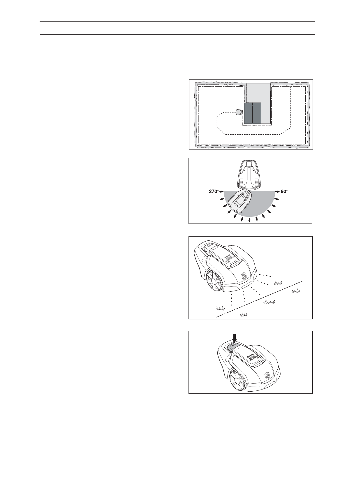
Automower
It continuously combines mowing and charging.
The mower starts to search for the charging station
when the battery charge becomes too low.
Automower
the charging station.
When Automower
it first searches irregularly for the guide wire. Then it
follows the guide wire to the charging station, turns
around just in front of the station and backs into it.
When the battery is fully charged, the mower leaves
the charging station and starts mowing in a randomly
selected direction within the 90˚ to 270˚ exit sector.
®
automatically mows the lawn.
®
does not mow when it is searching for
®
searches for the charging station,
In order to ensure an even cut, even in parts of the
garden that are hard to reach, there are a number of
manual settings for how the mower is to leave the
charging station, see 6.4 Installation (2) .
When Automower
®
body hits an obstacle, the mower
reverses and selects a new direction.
Two sensors, one at the front and one at the back on
®
Automower
boundary wire. Automower
, sense when the mower approaches the
®
overruns the wire by up
to 11" (28 centimetres) before it turns.
The STOP button on the top of Automower
®
is mainly
used to stop the mower when it’s running. When the
STOP button is pressed a cover opens, behind which
there is a control panel. The STOP button remains
depressed until the cover is closed again. This acts
as start inhibitor.
English - 13
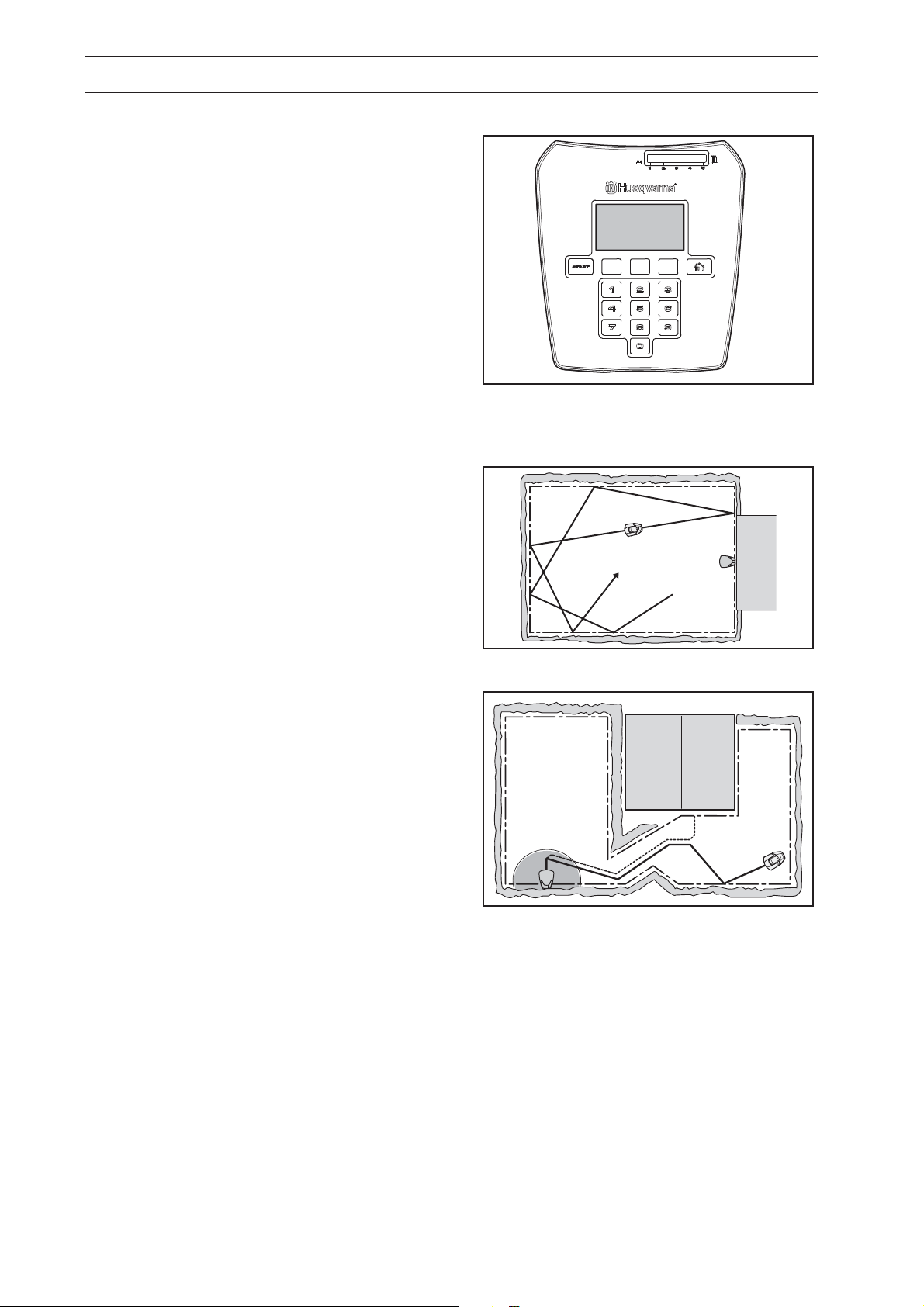
2. PRESENTATION
The control panel on the top of Automower
you manage all the mower settings. Open the control
panel cover by pressing down the STOP button.
When the main switch is set to position 1 for the first
time, a start-up sequence begins which includes:
When the main switch is set to position 1 for the first
time, a start-up sequence begins which includes:
language selection, time format, date format and the
four-digit PIN code and setting the time and date, see
3.8 First start-up and calibration on page 32.
After this, the selected PIN code must be entered
every time the main switch is set to 1 . See
6.5 Security (3) on page 47 for more information on
theft protection.
®
is where
Movement pattern
The mower’s movement pattern is irregular and is
determined by Automower® itself. A movement
pattern is never repeated. This mowing system
means the lawn is mown equally without any mowing
lines.
Locating the charging station
Automower® runs irregularly until it reaches the guide
wire. The mower then follows the guide wire in to the
charging station.
The guide wire is a cable that is laid from the charging
station towards, for instance, a remote part of the
working area or through a narrow passage to be then
connected with the boundary wire. For more
information, see 3.6 Installation of the guide wire.
14 - English

3. INSTALLATION
3. Installation
This chapter describes how you install the Husqvarna
Automower®. Before starting the installation read the
previous chapter 2. Presentation.
Read also through this entire chapter before beginning
the installation. How the installation is made also
affects how well Automower® will work. It is therefore
important to plan the installation carefully.
Planning is simplified if you make a sketch of the
working area, including all obstacles. This makes it
easier to see the ideal positions for the charging
station, the boundary wire and the guide wire. Draw on
the sketch where the boundary and guide wires should
be routed.
In chapter 7. Garden examples, there are examples of
installations.
Visit also www.automower.com for further descriptions
and tips regarding installation.
Carry out the installation in the following steps:
3.1 Preparations.
3.2 Installation of the charging station.
3.3 Charging the battery.
3.4 Installation of the boundary wire.
3.5 Connecting the boundary wire.
3.6 Installation of the guide wire.
3.7 Checking the installation.
3.8 First start-up and calibration
3.9 Test docking with the charging station
The charging station and boundary and guide wires
must be connected to be able to carry out a complete
start-up.
3.1 Preparations
1. If the lawn in the proposed working area is taller
than 4" (10 cm), mow it using a normal robotic
lawn mower. Then collect the clippings.
2. Read carefully through all the steps before the
installation.
3. Check that all parts for the installation are
included:
The numbers in brackets refer to the detail
diagram 2.1 What’s what?.
• Operator’s Manual (24)
• Automower®
English - 15
3. INSTALLATION
• Charging station (6)
• Loop wire for the boundary wire and guide
wire (16)
• Transformer (20)
• Low voltage cable (17)
• Staples (21)
• Connector for the loop wire (18)
• Screws for the charging station (19)
• Measurement gauge (22)
• Solderless coupler for the loop wire (23)
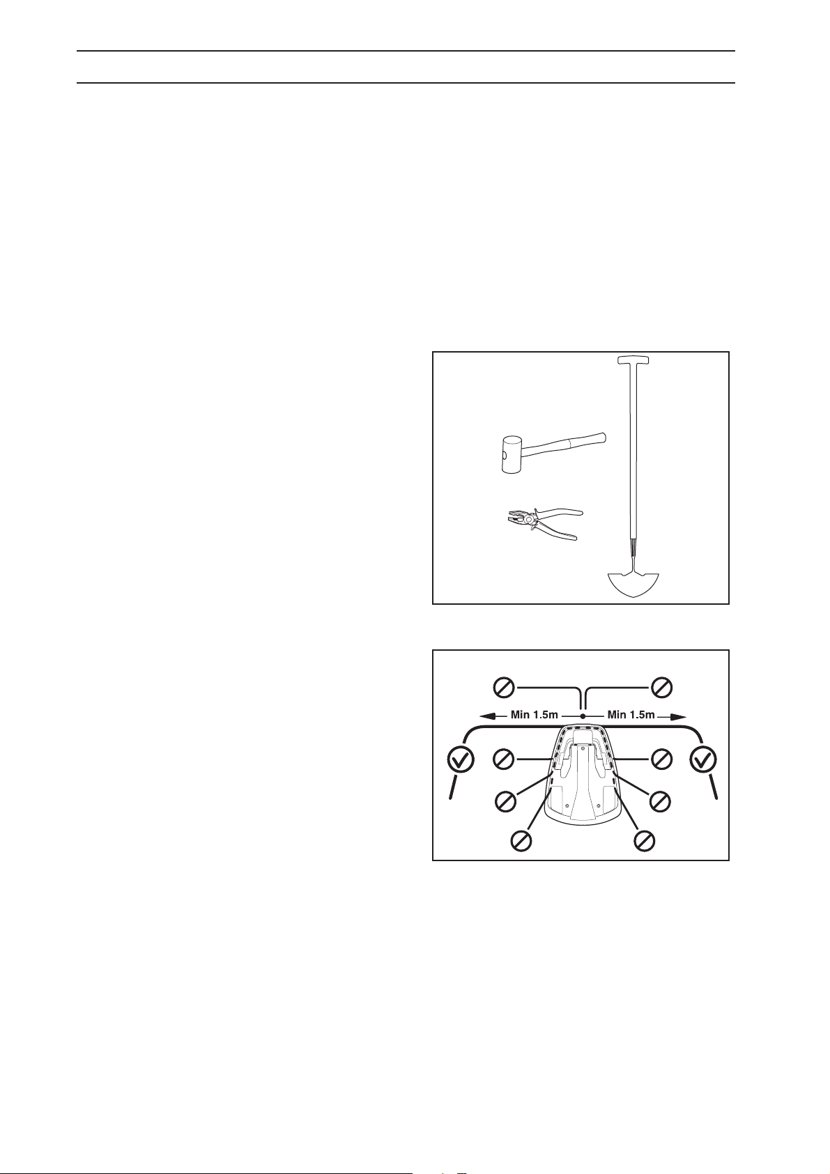
During installation you will also need:
• Hammer/plastic mallet to simplify putting the
staples in the ground
• Combination pliers for cutting the boundary
wire and pressing the contact units together.
• Edge cutter/straight spade if the boundary wire
must be buried. Installation of the charging
station
3.2 Installation of the charging
station
Ideal position of the charging station
Take the following aspects into consideration when
identifying the best location for the charging station:
• Allow for 10 feet (3 metres) of free space in
front of the charging station
• It must be possible to lay at least 4.9 feet
(1.5 metres) of boundary wire straight out to
the right and left of the charging station.
• Close to a wall socket. The supplied low
voltage cable is 33 feet (10 metres) long.
• A level surface on which to place the charging
station.
• Protection from water spray, for instance from
irrigation
• Protection from direct sunlight
• Place in the lower part of a working area that has
a major slope
• Possible requirement to keep the charging
station out of sight of outsiders
• Any aesthetic preferences
For examples of where best to install the charging
station, See 7. Garden example on page 50.
16 - English
3. INSTALLATION
The charging station must be positioned with a great
deal of free area in front of it (at least 10 ft/3 metres).
It should also be centrally placed in the working area
so that Automower® finds it easier to reach all areas
in the working area.
Do not put the charging station in confined spaces in
the working area. There must be a straight boundary
wire, at least 5 feet (1.5 metres) long, to the right and
left of the charging station. The wire must be laid
straight out from the rear end of the charging station.
Any other locations can mean that the lawn mower
enters the charging station sideways and will have
difficulty docking.
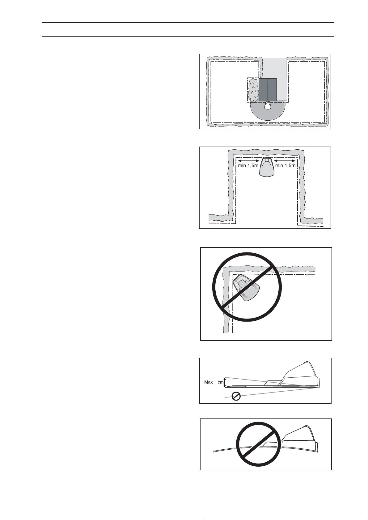
Do not put the charging station in a corner in the
working area.
The charging station must be positioned on relatively
level ground. The front end of the charging station
must be a maximum of 1.5” (3 cm) higher than the
back end. The front end of the charging station must
never be lower than the back end.
The charging station must not be positioned so that
its plate bends.
3020-043
3
English - 17
3. INSTALLATION
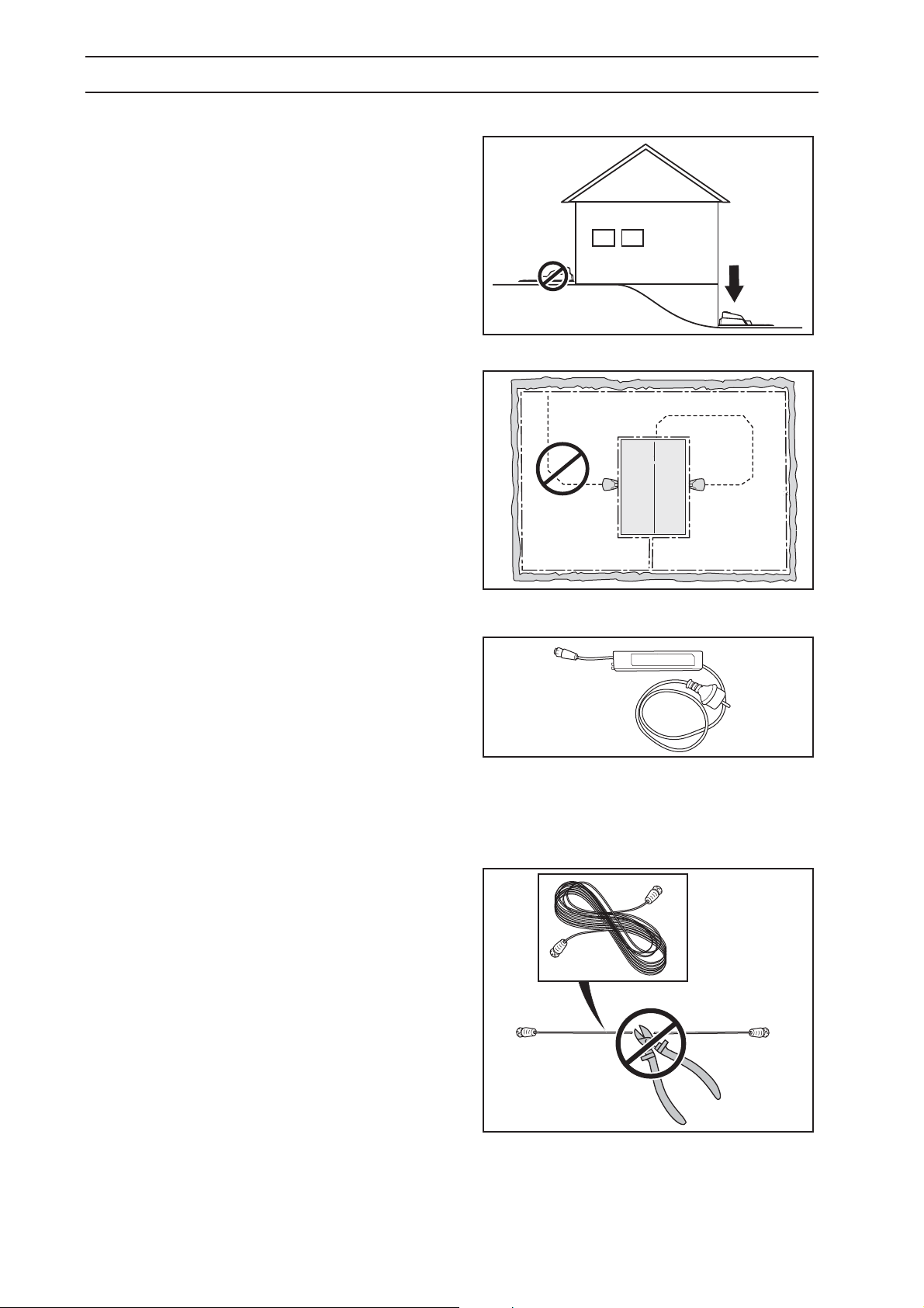
If the installation is done in a working area with a
steep slope (such as around a house on a hill), the
charging station should be placed in the area at the
bottom of the slope. This makes it easier for the lawn
mower to follow the guide wire to the charging station.
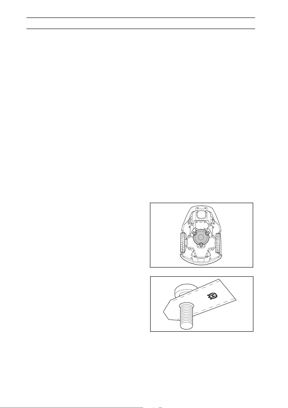
The charging station should not be placed on an
island as this limits the laying of the guide wire in an
optimal way. If the charging station has to be installed
on an island, the guide wire also has to be connected
to the island. See the picture opposite. Read more
about islands in chapter 3.4 Installation of the
boundary wire.
Connecting the transformer
Take the following into consideration when planning
where to place the transformer:
• Close to the charging station
• Protection from rain
• Protection from direct sunlight
If the transformer is connected to an electrical socket
outdoors, this must be approved for outdoor use. The
low voltage cable for the transformer is 33 feet
(10 metres) long, and may not be shortened or
extended.
It is possible to let the low voltage cable cross the
working area. The low voltage cable must be stapled
down or buried, and the cutting height should be such
that the blades on the blade disc can never come in
contact with the low voltage cable.
The transformer must be placed where it is well
ventilated and is not exposed to direct sunlight. The
transformer must be placed under a roof.
It is recommended to use an earth fault-breaker when
connecting the transformer to the wall socket.
For best performance, the transformer must not be
exposed to direct sunlight.
18 - English
3. INSTALLATION
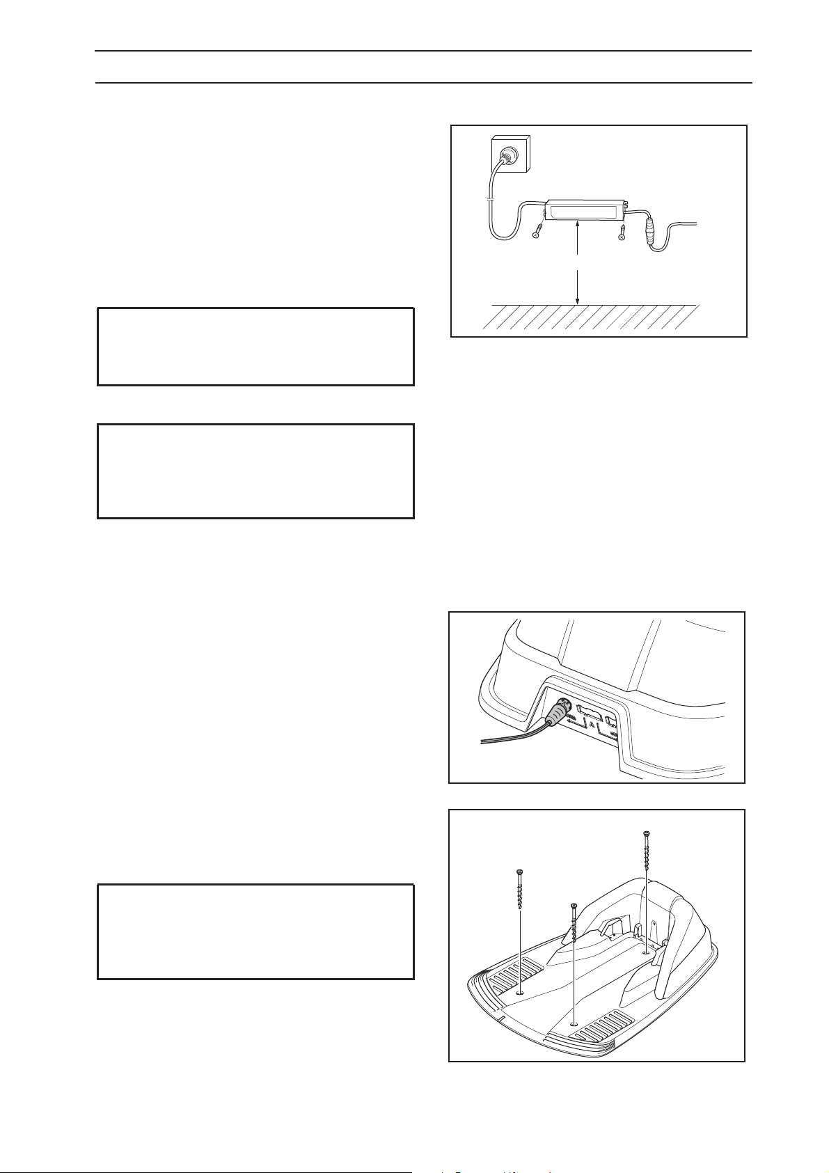
The transformer shall be mounted on a vertical
surface, for example a house wall. Mount the
transformer with screws in the two attachment points.
Securing screws are not included. Choose screws
suitable for the wall material.
Mount the transformer at a height such that there is
no risk the transformer can become submerged in
water (minimum 12”/30 cm from the ground). The
transformer must never be placed on the ground.
IMPORTANT INFORMATION
The low voltage cable must not be shortened
nor extended.
IMPORTANT INFORMATION
Place the low voltage cable so that the blades
on the blade disc can never come in contact
with it.
min 30cm/12”
Installation and connecting the charging
station
1. Position the charging station in a suitable spot.
2. Connect the low voltage cable to the charging
station.
3. Connect the transformer’s power cable to a
230 V wall socket. If the wall socket is outdoors,
it is important that the transformer is protected
from direct sunlight.
4. Attach the charging station to the ground using
the supplied screws. Ensure the screws are
screwed all the way down in the countersink.
IMPORTANT INFORMATION
It is not permitted to make new holes in the
plate. Only the existing holes may be used to
secure the plate to the ground.
English - 19
3. INSTALLATION
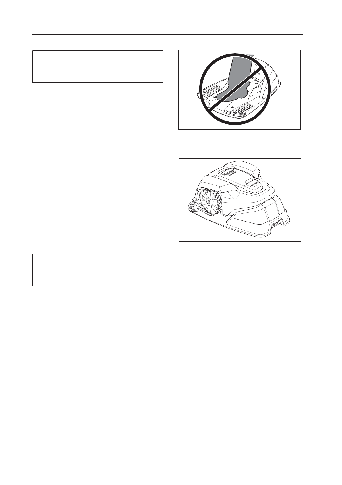
IMPORTANT INFORMATION
Do not tread or walk on the charging station
plate.
3.3 Charging the battery
As soon as the charging station is connected, it is
possible to charge the mower.
The mower can be charged as soon as the charging
station is connected. Set the main switch to the
1 position.
Place Automower® in the charging station to charge
the battery while the boundary and guide wires are
being laid.
If the battery is empty, it takes around 3 hours to fully
charge it.
If the battery charge is low, it takes around 80 to
100 minutes to fully charge it.
IMPORTANT INFORMATION
Automower
installation is complete.
®
cannot be used before the
20 - English
3. INSTALLATION
3.4 Installation of the boundary wire
The boundary wire can be installed in one of the following ways:
1. Securing the wire to the ground with staples.
It is preferable to staple down the boundary wire if you want to make adjustments to the boundary wire
during the first few weeks of operation. After a few weeks the grass will have grown over the wire
making it no longer visible. Use a hammer/plastic mallet and the staples supplied when carrying out
the installation.
2. Bury the wire.
It is preferable to bury the boundary wire if you want to dethatch or aerate the lawn. If necessary both
methods can be combined so one part of the boundary wire is stapled down and the remainder is
buried. For instance, the wire can be buried using an edge cutter or a straight spade. Make sure to lay
the boundary wire at least 0.4” (1 cm) and a maximum of 8” (20 cm) in the ground.
Plan where to lay the boundary wire
The boundary wire must be laid so it:
• Forms a loop around the working area for the robotic lawn mower. Only Husqvarna boundary wire
must be used. It is specially designed to resist dampness from the soil that could otherwise easily
damage the wires.
• The mower is never more than 49 feet (15 metres) from the wire at any point in the entire working
area.
• The wire is no more than 820 feet (250 metres) long.
• 8” (20 cm) of extra wire is available to which the guide wire will be connected later. See
3.6 Installation of the guide wire on page 28.
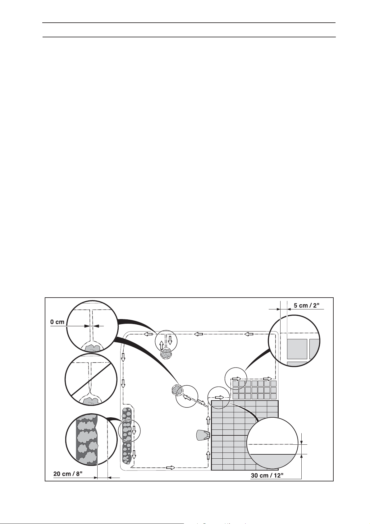
Depending on to what the working area is adjacent, the boundary wire must be at laid at different distances
from obstacles. The illustration below shows how the boundary wire must be laid around the working area
and around obstacles. Use the supplied measurement gauge to obtain the correct distance (see
2.1 What’s what? on page 11).
English - 21
 Loading...