

Page 1
Item # 723883
Model # C301H
USE AND CARE GUIDE
30 GALLON PORTABLE AIR COMPRESSOR
Questions, problems, missing parts?
Before returning to the store, call
Husky Customer Service
8 a.m – 6 p.m., EST, Monday-Friday
1-888-43-HUSKY
HUSKYTOOLS.COM
THANK YOU
We appreciate the trust and condence you have placed in Husky through the purchase of this 30 gallon
portable air compressor. We strive to continually create quality products designed to enhance your home.
Visit us online to see our full line of products available for your home improvement needs. Thank you for
choosing Husky!
Page 2
2
Table of Contents
Safety Information ............................. 2
Work Area Safety ............................2
Personal Safety ..............................3
Transporting ...................................3
Air Compressor And
Pneumatic Tool Safety ....................3
Electrical Safety ..............................4
Electrical Safety
(Extension Cords) ...........................4
Electrical Safety
(Electrical Connection) ...................5
Electrical Safety
(Speed And Wiring) .........................5
Electrical Safety
(Grounding Instructions) ................5
Warranty ............................................. 6
Specications ..................................... 6
Duty Cycle........................................... 6
Package Contents ............................... 7
Assembly ............................................ 9
Operation ......................................... 10
Maintenance ..................................... 12
Storage ............................................. 16
Troubleshooting ................................ 16
Safety Information
This manual contains information that is
important for you to know and understand.
This information relates to protecting YOUR
SAFETY and PREVENTING EQUIPMENT
PROBLEMS. To help you recognize this
information, we use the symbols below.
Please read the manual and pay attention to
these symbols.
DANGER: Indicates an
imminently hazardous situation
which, if not avoided, will result
in death or serious injury.
WARNING: Indicates a
potentially hazardous situation
which, if not avoided, could
result in death or serious
injury.
CAUTION: Indicates a potentially
hazardous situation which, if not
avoided, may result in minor or
moderate injury.
NOTICE: Indicates a practice
not related to personal injury
which, if not avoided, may result
in property damage.
WORK AREA SAFETY
1. Keep your work area clean and well lit.
Ensure oors are not slippery from wax
or dust.
2.
Do not operate power
tools in explosive
atmospheres, such as in
the presence of ammable liquids, gases,
or dust. Power tools create sparks which
may ignite the dust or fumes. Keep
bystanders, children, and visitors away
while operating tools. Distractions can
cause you to lose control.
3. Operate air compressor in an open area
at least 18 in. (0.5m) away from any
wall or object that could restrict the
ow of fresh air to ventilation openings.
4.
Always disconnect the air
supply and power supply before
making adjustments, servicing a
tool, or when a tool is not in use.
5.
This compressor/pump is not
equipped and should not be
used to supply breathing
quality air. Additional equipment would
be necessary to properly lter and
purify the air to meet minimal
specications for Grade D breathing as
described in Compressed Gas
Association Commodity Specication G
7.1 - 1966, OSHA 29 CF9 1910.134.
Compressed Gas Association, 4221
Walney Road, Fifth Floor, Chantilly, VA
20151-2923, (703) 788-2700, www.
cganet.com. Any such additional
Page 3
3
HUSKYTOOLS.COM
Please contact 1-888-43-HUSKY for further assistance.
pts-205109-051012
equipment has not been examined and
no implication of proper use for
breathing air is intended or implied.
PERSONAL SAFETY
WARNING: Operating any
power tool can result in foreign
objects being thrown into your
eyes, which can result in severe
eye damage. Before beginning
operation, always wear safety
goggles, safety glasses with
side shields, or a full face shield
when needed. Always use eye
protection marked to comply
with ANSI Z87.1.
WARNING: This product
contains chemicals known to
the State of California to cause
cancer and birth defects or other
reproductive harm. Wash hands
after handling.
1.
Use safety equipment.
Always wear eye
protection with side
shields when operating power tools.
Dust mask, nonskid safety shoes, hard
hat, or hearing protection must be used
for appropriate conditions.
2.
Stay alert when operating a
power tool. Do not use the tool
while tired or under the
inuence of drugs, alcohol, or medication.
3.
Do not wear loose
clothing or jewelry.
Contain long hair. Keep
your hair, clothing, and gloves away
from moving parts. Loose clothes,
jewelry, or long hair can be caught in
moving parts.
4. Keep proper footing and balance at
all times. Proper footing and balance
enables better control of the tool in
unexpected situations
5. Do not use on a ladder or unstable support.
6.
Never touch any exposed metal
parts on compressor during or
immediately after operation.
Compressor will remain hot for several
minutes after operation. Do not reach
around protective shrouds or attempt
maintenance until unit has been
allowed to cool.
8.
The compressor is too heavy to be
lifted by one person. Obtain
assistance from others before lifting.
TRANSPORTING
1. Always place compressor on a
protective mat when
transporting to protect against
damage to vehicle from leaks. Remove
compressor from vehicle immediately
upon arrival at your destination.
2. Always transport and store unit in an
upright position.
AIR COMPRESSOR AND
PNEUMATIC TOOL SAFETY
WARNING: Do not attempt
to modify this tool or create
accessories not recommended
for use with this tool. Any such
alteration or modication is
misuse and could result in a
hazardous condition leading to
possible serious personal injury.
CAUTION: Do not use in an
environment that is dusty or
otherwise contaminated. Using
the air compressor in this type of
environment may cause damage
to the unit.
1. Keep compressors as far from the
spraying area as possible, at least 15 ft.
(0.4m) from the spraying area and all
explosive vapors.
2.
Risk of Bursting. Do not adjust
regulator to result in output
pressure greater than marked
maximum pressure of attachment. Do not
use at pressure greater than the rated
maximum pressure of this compressor.
3. If connected to a circuit protected by fuses,
use time-delay fuses with this product.
Safety Information (continued)
Page 4
4
4. To reduce the risk of electric
shock, do not expose to rain.
Store indoors.
5. Ensure the hose is free of obstructions
or snags. Entangled or snarled hoses
can cause loss of balance or footing and
may become damaged.
6. Use the air compressor only for its
intended use. Do not alter or modify the
unit from the original design or function.
Never weld or drill holes in the air tank.
7. Never leave a tool unattended with the
air hose attached.
8. Do not operate this tool if it does not
contain a legible warning label.
9. Do not continue to use a tool or hose that
leaks air or does not function properly.
10. Do not attempt to pull or carry the air
compressor by the hose.
11. Your tool may require more air
consumption than this air compressor is
capable of providing.
12. Never direct a jet of compressed air
toward people or animals.
13. Protect your lungs. Wear a face or dust
mask if the operation is dusty.
14. Do not use this air compressor to spray
chemicals. Your lungs can be damaged
by inhaling toxic fumes. A respirator
may be necessary in dusty environments
or when spraying paint.
ELECTRICAL SAFETY
1. Avoid body contact with grounded
surfaces such as pipes, radiators, ranges,
and refrigerators. There is an increased risk
of electric shock if your body is grounded.
2. Do not expose power tools to rain or wet
conditions. Water entering a power tool
will increase the risk of electric shock.
3. Replace damaged cords/wiring
immediately. Damaged cords/wiring
increase the risk of electric shock.
ELECTRICAL SAFETY (EXTENSION CORDS)
WARNING: Keep the extension
cord clear of the working
area. Position the cord so
that it will not get caught
on lumber, tools, or other
obstructions while you are
working with a power tool.
Failure to do so can result in
serious personal injury.
WARNING: Check extension
cords before each use.
If damaged, replace
immediately. Never use the air
compressor with a damaged
cord since touching the
damaged area could cause
electrical shock resulting in
serious personal injury.
WARNING: Improperly
connecting the equipmentgrounding conductor can
result in a risk of electrical
shock
1. Use only 3-wire extension cords that
have 3-prong grounding plugs and
3-pole receptacles that accept the air
compressor’s plug. Make sure your
extension cord is not damaged.
2. When using the air compressor at a
considerable distance from the power
source, use an extension cord heavy
enough to carry the current that the
compressor will draw. An undersized
extension cord will cause a drop in line
voltage, resulting in a loss of power
and causing the motor to overheat.
Use the following chart to determine
the minimum wire size required in an
extension cord.
3. Only use 100 feet or less round
jacketed cords listed by Underwriter’s
Laboratories (UL).
4. When operating a power tool outside,
use an outdoor extension cord marked
“W-A” or “W”. These cords are rated
for outdoor use and reduce the risk of
electric shock.
Safety Information (continued)
Page 5
5
HUSKYTOOLS.COM
Please contact 1-888-43-HUSKY for further assistance.
pts-205109-051012
NOTE: Use longer air hoses
instead of long extension cords.
Your air compressor will run
better and last longer.
ELECTRICAL SAFETY
(ELECTRICAL CONNECTION)
1. This air compressor is powered by a
precision built electric motor. It should
be connected to a power supply that
is 120 volts, 60 Hz, AC only (normal
household current).
2. Do not operate this tool on direct
current (DC). A substantial voltage
drop will cause a loss of power and
the motor will overheat. If the air
compressor does not operate when
plugged into an outlet, double check the
power supply.
ELECTRICAL SAFETY (SPEED AND WIRING)
1. The no-load speed of the electric motor
varies by model and specication.
The motor speed is not constant and
decreases under a load or with lower
voltage. For voltage, the wiring in a
shop is as important as the motor’s
horsepower rating.
2. A line intended only for lights cannot
properly carry a power tool motor.
Wire that is heavy enough for a short
distance will be too light for a greater
distance. A line that can support one
power tool may not be able to support
two or three tools.
ELECTRICAL SAFETY
(GROUNDING INSTRUCTIONS)
1. This product must be grounded. In
the event of an electrical short circuit,
Safety Information (continued)
grounding reduces the risk of electric
shock by providing an escape wire for
the electric current. This air compressor is
equipped with an electric cord having an
equipment-grounding conductor and a
grounding plug. The plug must be plugged
into a matching outlet that is properly
installed and grounded in accordance
with all local codes and ordinances.
2. Check with a qualied electrician
or serviceman when the grounding
instructions are not completely
understood, or when in doubt as
to whether the product is properly
grounded. Do not modify the plug
provided. If it does not t the outlet,
have the proper outlet installed by a
qualied electrician.
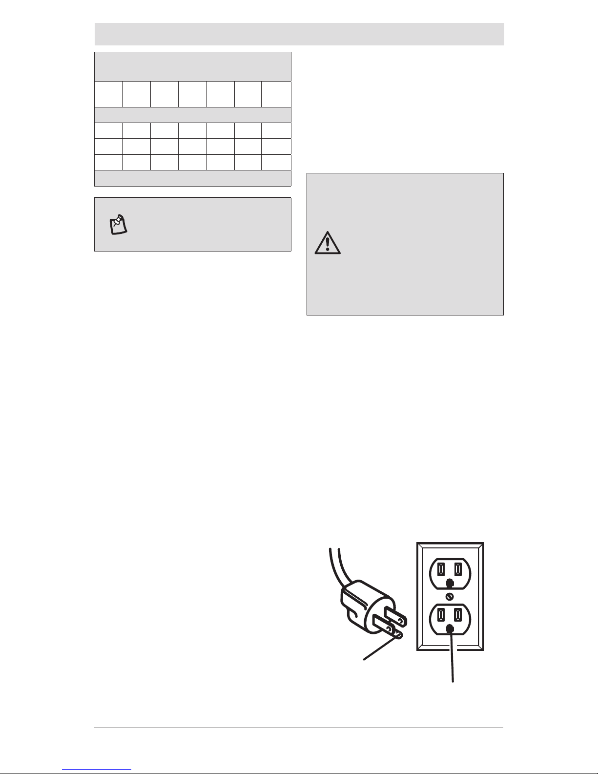
3. This product is for use on a nominal
120-V circuit and has a grounding plug
illustrated in Figure 1. Only connect the
product to an outlet having the same
conguration as the plug. Do not use an
adapter with this product.
Ampere rating
(on air compressor data plate)
0-2.0
2.1-
3.4
3.5-
5.0
5.1-
7.0
7.1-
12.0
12.1-
16.0
Cord Length
25´ 16 16 16 16 14 14
50´ 16 16 16 14 14 12
100´ 16 16 14 12 10 -
Used on 12 gauge - 20 amp circuit.
WARNING: Improper installation
of the grounding plug is able to
result in a risk of electric shock.
When repair or replacement of
the cord or plug is required, do
not connect the grounding wire
to either at blade terminal. The
wire with insulation having an
outer surface that is green with
or without yellow stripes is the
grounding wire.
GROUNDING PIN
120V GROUNDED OUTLET
FIGURE 1
Page 6
6
Warranty
HUSKY AIR COMPRESSOR
LIMITED TWO-YEAR
WARRANTY
This warranty covers defects in workmanship
or materials in this Husky air compressor
for the two-year period from the date of
purchase. This warranty is specic to this
air compressor model. Warranties for other
Husky products may vary.
This warranty applies only to the original
retail purchaser and may not be transferred.
This warranty does not cover normal wear
and tear or any malfunction, failure or
defect resulting from misuse, abuse, neglect,
alteration, modication or repair by other
than a service center authorized to repair
Husky branded air compressors. Expendable
materials, such as motor brushes, seals,
etc. are not covered by this warranty. This
warranty does not apply to this compressor
used in industrial applications or for rental
purposes. Husky makes no warranties,
representations or promises as to the quality
or performance of its air compressors other
than those specically stated in this warranty.
ADDITIONAL LIMITATIONS
To the extent permitted by applicable law, all implied warranties, including warranties of
merchantability or tness for a particular purpose, are disclaimed. Any implied warranties,
including warranties of merchantability or tness for a particular purpose, that cannot be
disclaimed under state law are limited to two years from the date of purchase. Husky is
not responsible for direct, indirect, incidental, special or consequential damages. If this air
compressor is used for commercial purposes, the warranty will apply for ninety (90) days from
the date of purchase. Some states do not allow limitations on how long an implied warranty
lasts and/or do not allow the exclusion or limitation of incidental or consequential damages,
so the above limitations may not apply to you. This warranty gives you specic legal rights,
and you may also have other rights, which vary from state to state.
Please contact the Customer Service Team at 1-888-43-HUSKY or visit www.huskytools.com.
Specications
AIR COMPRESSOR
Running horsepower 1.6 HP
Air tank capacity 30 gal.
Air pressure 135 PSI max.
Air delivery 6.2 SCFM at 40 PSI
5.3 SCFM at 90 PSI
Lubrication Oil Lube
Input
120V, 60 Hz, Single Phase
AC only, 15 Amps.
Minimum Branch Circuit
Requirement
15A
Fuse Type Time Delay
Net weight 148 lbs.
Duty Cycle
This air compressor pump is capable of running continuously. However, to prolong the life of
your air compressor, it is recommended that a 50% average duty cycle be maintained; that is,
the air compressor pump should not run more than 30 minutes in any given hour.
Page 7
7
HUSKYTOOLS.COM
Please contact 1-888-43-HUSKY for further assistance.
pts-205109-051012
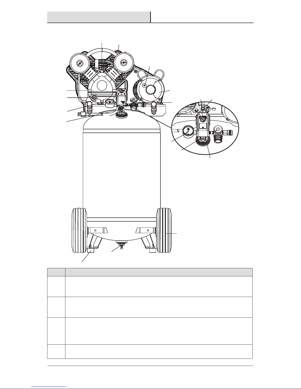
Package Contents
Become familiar with these controls before operating the unit (Figure 2)
Part Description
A
Auto(I)/Off(0) Switch: Turn this switch in the “Auto (I)” position to provide
automatic power to the pressure switch and “Off (O)” to remove power at the end
of each use.
B
Pressure Switch: The pressure switch automatically starts the motor when the air
tank pressure drops below the factory set “cut-in” pressure. It stops the motor when
the air tank pressure reaches the factory set “cut-out” pressure.
C
Safety Valve: If the pressure switch does not shut off the air compressor at its
“cut-out” pressure setting, the safety valve will protect against high pressure by
“popping out” at its factory set pressure (slightly higher than the pressure switch
“cut-out” setting).
D
Tank Pressure Gauge: The tank pressure gauge indicates the reserve air pressure
in the tank.
A
B
C
D
E
F
G
H
I
J
K
L
M
N
O
Q
P
Page 8
8
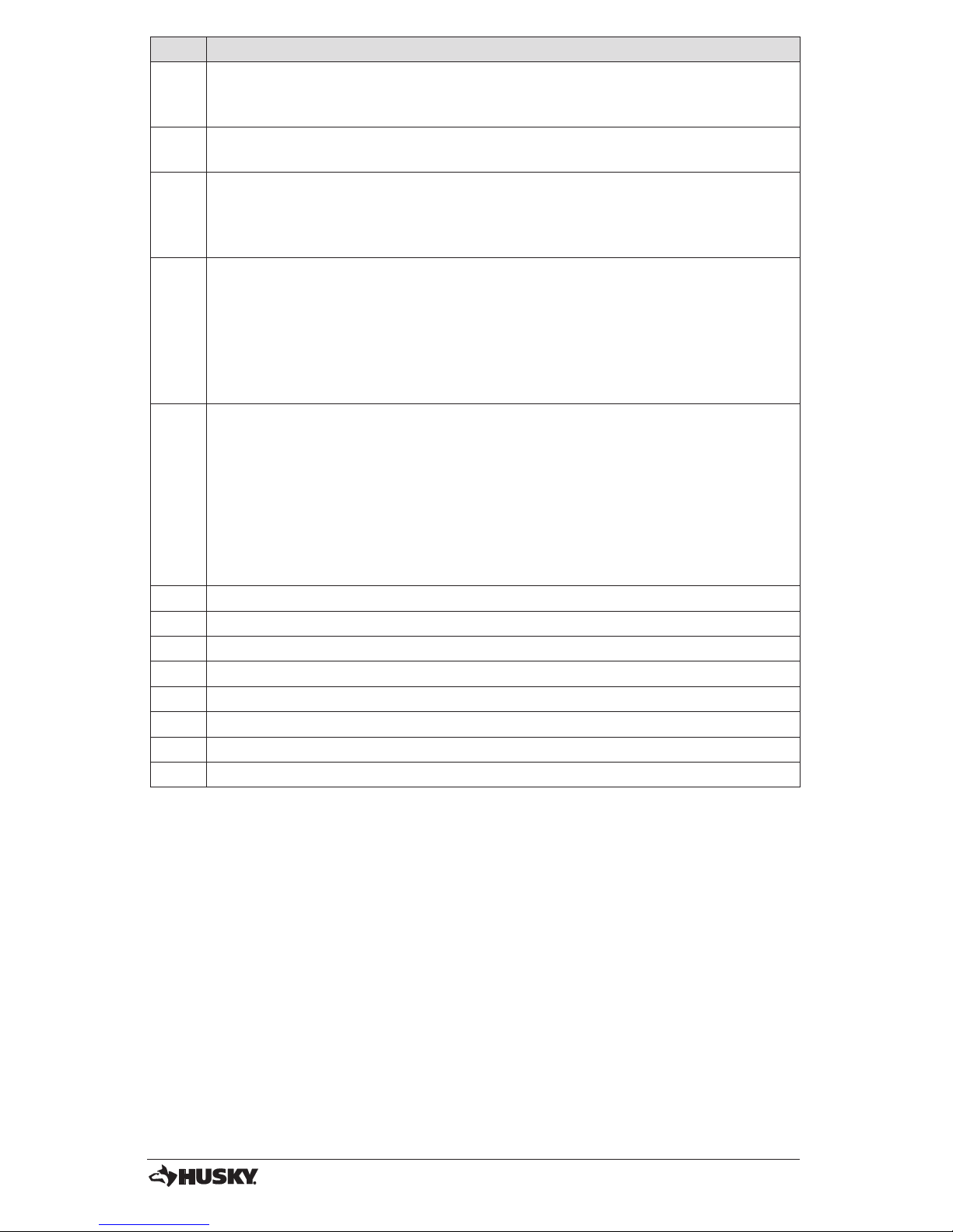
Part Description
E
Air Compressor Pump: Compresses air into the air tank. Working air is not
available until the compressor has raised the air tank pressure above that required
at the air outlet.
F
Drain Valve: The drain valve is located at the base of the air tank and is used to
drain condensation at the end of each use.
G
Check Valve: When the air compressor is operating, the check valve is “open”,
allowing compressed air to enter the air tank. When the air compressor reaches
“cut-out” pressure, the check valve “closes”, allowing air pressure to remain inside
the air tank.
H
Pressure Release Valve: The pressure release valve located on the side of the
pressure switch, is designed to automatically release compressed air from the
compressor head and the outlet tube when the air compressor reaches “cut-out”
pressure or is shut off. The pressure release valve allows the motor to restart freely.
When the motor stops running, air will be heard escaping from this valve for a few
seconds. No air should be heard leaking when the motor is running or after the unit
reaches “cut-out” pressure.
I
Motor Overload Reset: This motor has a manual thermal overload protector. If the
motor overheats for any reason, the overload protector will shut off the motor. The
motor must be allowed to cool down before restarting. To restart:
1. Place the Auto/Off switch in the “Off” position.
2. Allow the motor to cool.
3. Depress the red reset button on the motor.
4. Place the Auto/Off switch in the “Auto” postion to restart the motor.
J Compressor Feet
K Belt Guard
L Pump Oil Fill
M Pump Oil Drain
N Pump Oil Sight Glass
O Motor
P Regulated Pressure Gauge
Q Wheels
Page 9

9
HUSKYTOOLS.COM
Please contact 1-888-43-HUSKY for further assistance.
pts-205109-051012
Assembly
1
Location of the air compressor
1. Locate the air compressor in a clean, dry, and well ventilated area.
2. Located the air compressor at least 18 in. (0.5m) away from the wall or other
obstructions that will interfere with the ow of air.
3. Locate the air compressor as close to the main power supply as possible to avoid
using long lengths of electrical wiring. NOTE: Long lengths of electrical wiring could
cause power loss to the motor.
4. The air lter must be kept clear of obstructions which could reduce air ow to the air
compressor.
2
Breaking in the pump
NOTICE: Risk of property damage. Serious damage may result if the
following break-in instructions are not closely followed.
This procedure is required before the air compressor is put into service and when the check
valve or a complete compressor pump has been replaced.
1. Make sure the Auto/Off switch (A) is in the “Off” position.
2. Check oil level in pump. See Oil paragraph in the Maintenance section for instructions.
3. Recheck all wiring. Make sure wires are secure at all terminals connections. Make sure all
contacts move freely and are not obstructed.
4. Open the drain valve (F) fully to permit air to escape and prevent air pressure build up in
the air tank during the break-in period.
5. Move the Auto/Off switch (A) to “Auto” position. The compressor will start.
6. Run the air compressor for 20 minutes. Make sure the drain valve and all air lines are
open so there is only a minimal air pressure build-up in tank.
7. Check all air line ttings and connections/piping for air leaks by applying a soap solution.
Correct if necessary.
NOTICE: Minor leaks can cause the air compressor to overwork, resulting in
premature breakdown or inadequate performance.
8. Check for excessive vibration. Readjust or shim air compressor feet, if necessary.
9. After 20 minutes, close the drain valve. The air receiver will ll to “cut-out” pressure and
the motor will stop.
The air compressor is now ready for use.
Page 10
10
Operation
1
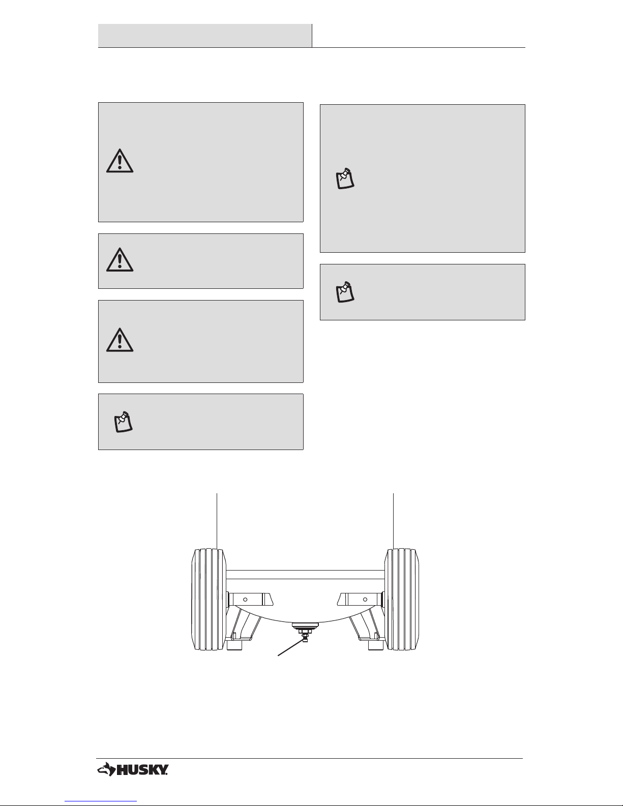
Draining the tank (Figure 2, 4)
WARNING: Risk of unsafe
operation. Air tanks contain
high pressure air. Keep face
and other body parts away
from outlet of drain. Use eye
protection [ANSI Z87.1 (CAN/
CSA Z94.3)] when draining as
debris can be kicked up into
face.
WARNING: Risk from noise.
Use ear protection (ANSI
S12.6 (S3.19) as air ow noise
is loud when draining.
WARNING: Risk of bursting.
Water will condense in the
air tank. If not drained, water
will corrode and weaken the
air tank causing a risk of air
tank rupture.
NOTICE: Risk of property
damage. Drain water from air
tank may contain oil and rust
which can cause stains.
NOTICE: All compressed air
systems generate condensate
that accumulates in any
drain point (e.g., tanks, lter,
aftercoolers, dryers). This
condensate contains lubricating
oil and/or substances which
may be regulated and must be
disposed of in accordance with
local, state, and federal laws and
regulations.
NOTICE: If drain valve is
plugged, release all air pressure.
The valve can then be removed,
cleaned, then reinstalled.
1. Set the Auto/Off switch (A, Figure 2) to
“Off”.
2. Slowly bleed the air from the air tank
and air distribution system until tank
pressure is approximately 20 psi.
3. Drain water from air tank by opening
drain valve (F) on bottom of tank.
4. After the water has been drained, close
the drain valve. The air compressor can
now be stored.
F
FIGURE 4
Page 11
11
HUSKYTOOLS.COM
Please contact 1-888-43-HUSKY for further assistance.
pts-205109-051012
2
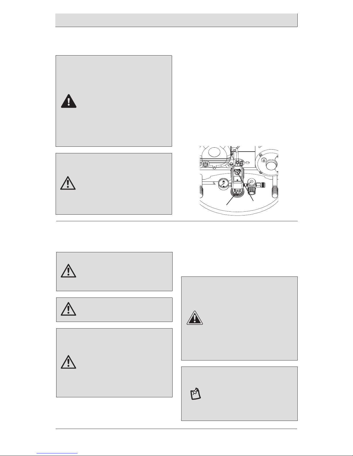
Checking the safety valve
(Figure 5)
DANGER: Do not tamper with
the safety valve. Items loosened
from this device could y up
and hit you. Failure to heed this
warning could result in death or
serious personal injury. The safety
valve automatically releases
air when the receiver pressure
exceeds the preset maximum.
Check the valve before each
day of use by pulling the ring by
hand.
WARNING: If air leaks after
releasing the safety valve ring
or if the valve is stuck, do not
use the air compressor until the
safety valve has been replaced.
Using the air compressor in this
condition could result in serious
personal injury.
3
Before each start-up
(Figure 5)
WARNING: Risk of unsafe
operation. Firmly grasp air
hose in hand when installing
or disconnecting to prevent
hose whip.
WARNING: Risk of unsafe
operation. Do not use
damaged or worn accessories.
WARNING: Risk of bursting.
Too much air pressure causes
a hazardous risk of bursting.
Check the manufacturer’s
maximum pressure rating
for air tools and accessories.
The regulator outlet pressure
must never exceed the
maximum pressure rating.
1. Place Auto/Off switch (A, Figure 5) to
“Off”.
Operation (continued)
1. Set the Auto/Off switch (A) to “On”.
and wait for the tank to ll. The
compressor automatically shuts off
when the pressure reaches the preset
maximum.
2. Set the Auto/Off switch (A) to “Off”.
3. Pull the ring on the safety valve (C) for
20 seconds to release the air.
4. Release the ring. Air stops escaping at
about 20 psi. If air continues to escape
after releasing the safety valve ring,
discontinue use and seek service before
using the air compressor again.
2. Close the air discharge outlet.
3. Visually inspect air lines and ttings for
leaks.
4. Check safety valve. See Checking the
Safety Valve paragraph.
CAUTION: Risk of unsafe
operation. Compressed air
from the unit may contain
wa ter condensation and oil
mist. Do not spray un l tered
air at an item that could be
damaged by moisture. Some
air tools and accessories may
require ltered air. Read the
in struc tions for the air tools
and accessories.
NOTICE: A regulator MUST be
installed when using accessories
rated at less than 135 psi.
The hose or accessory will require
a quick connect plug if the air
outlet is equipped with a quick
connect socket.
C
A
FIGURE 5
Page 12
12
4
How to start (Figure 2)
1. Turn the Auto/Off switch (A, Figure2))
to “Auto” and allow tank pressure
to build. Motor will stop when tank
pressure reaches “cut-out” pressure.
2. When the tank pressure reaches “cutout” pressure open the air discharge
valve.
WARNING: Risk of bursting. If
any unusual noise or vibration
is noticed, stop the air
compressor immediately and
have it checked by a trained
service technician.
NOTICE: When using regulator
and other accessories refer to the
manufacturers instructions.
Maintenance
GENERAL MAINTENANCE
Condensate forms in the tank when
there is humidity in the air. Depending
on the environmental conditions, drain
the condensate daily and/or every hour.
For instructions, see Draining the tank
paragragh under Operation.
The safety valve automatically releases air
when the receiver pressure exceeds the
preset maximum.
Inspect the tank annually for rust, pin holes,
or other imperfections that could cause it to
become unsafe.
Avoid using solvents when cleaning plastic
parts. Most plastics are susceptible to
damage from various types of commercial
solvents and may be damaged by their use.
Use clean cloths to remove dirt, dust, oil,
grease, etc.
WARNING: Do not allow brake
uids, gasoline, petroleum based
products, etc., to come in contact
with plastic parts. Chemicals can
weaken or destroy plastic which,
may result in serious personal
injury.
WARNING: When servicing, use
only identical Husky replacement
parts. Use of any other parts may
create a hazard or cause product
damage.
WARNING: Always disconnect
the air compressor from the
power supply, release all
pressure, and allow it to cool
before cleaning or making repairs
on the air compressor.
Operation (continued)
Page 13
13
HUSKYTOOLS.COM
Please contact 1-888-43-HUSKY for further assistance.
pts-205109-051012
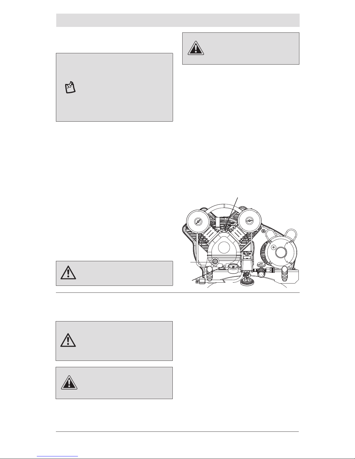
1
Oil (Figure 6)
NOTICE: Risk of property
damage. Use air compressor oil
only. Multi-weight automotive
engine oils like 10W30 should
not be use in air compressors.
They leave carbon deposits
on critical components, thus
reducing performance and
compressor life.
NOTE: Use 30W compressor oil or a heavy
duty SAE 30W, non-detergent, SF grade
or better oil. DO NOT use multi-weight
automotive engine oils, they will reduce
compressor life. Under extreme winter
condition use SAE-10 weight oil.
NOTE: Crankcase oil capacity is
approximately 10.6 uid ounces (313,5 ml).
Checking
1. The oil level should be to the middle of
the sight glass (N).
2. If needed remove oil ll plug (L) and
slowly add oil until it reaches the middle
of the sight glass.
Changing
WARNING: Drain tank to release
air pressure before removing the
oil ll cap or oil drain plug.
2
Air Filter
WARNING: Hot surfaces. Risk
of burn. Compressor heads are
exposed when lter cover is
removed. Allow compressor to
cool prior to servicing.
CAUTION: Keep the air lter
clean at all times. Do not operate
the air compressor with the air
lter removed.
A dirty air lter will not allow the air
compressor to operate at full capacity. Keep
the air lter clean at all times.
1. Remove the air lter cover.
2. Remove the air lter from lter cover.
4. Place new air lter into lter cover.
5. Replace air lter cover to pump.
CAUTION: Overlling with
oil will cause premature air
compressor failure. Do not
overll.
1. Remove the oil ll plug (L).
2. Remove the oil drain plug (M) and
drain oil into a suitable container.
3. Replace the oil drain plug (M) and
tighten securely
4. Slowly add compressor oil until it
reaches the middle of the sight glass
(N).
NOTE: When lling the crankcase, the
oil ows very slowly into the pump.
If the oil is added too quickly, it will
overow and appear to be full.
5. Replace oil ll plug (L) and tighten
securely.
Maintenance (continued)
L
N
M
FIGURE 6
Page 14

14
3
BELT GUARD – REMOVAL
1. Turn air compressor off, lock out
the power supply, and relieve all air
pressure from the air tank.
2. Remove the four screws from the belt
guard. The front belt guard can now
lifted up and away from unit.
Operation (continued)
4
Belt - Replacement
WARNING: Serious injury or
damage may occur if parts of
the body or loose items get
caught in moving parts. Never
operate the outt with the belt
guard removed. The belt guard
should be removed only when
the air compressor power is
disconnected.
1. Turn air compressor off, lock out
the power supply, and relieve all air
pressure from the air tank.
2. Remove the belt guard.
3. Mark pump position on saddle.
4. Loosen the motor mounting screws
and slide the motor toward the air
compressor.
5. Remove the belt and replace with a
new one.
6. See the Adjust Belt Tension before
tightening motor mounting screws.
5
Adjusting Belt Tension
(Figure 7)
1. Slide motor into original position, line
the motor up with the mark made
earlier on saddle.
2. Tighten two outside motor mounting
screws enough to hold the motor in
place for checking pulley and ywheel
alignment.
3. The belt should deect 1/2˝ (12.7mm)
at midway between the pulley and the
ywheel when a 5 pound (2.26kg.)
weight is applied at the midway point.
4. When proper belt tension is achieved,
tighten all four motor mounting screws.
Torque to 15-20 ft-lbs (20-27Nm).
NOTICE: Once the engine pulley
has been moved from its factory
set location, the grooves of
the ywheel and pulley must
be aligned to within 1/16”
(1.6mm) to prevent excessive
belt wear. Verify the alignment by
performing the following Pulley
and Flywheel - Alignment.
FIGURE 7
Downward Force
Deection
Page 15
15
HUSKYTOOLS.COM
Please contact 1-888-43-HUSKY for further assistance.
pts-205109-051012
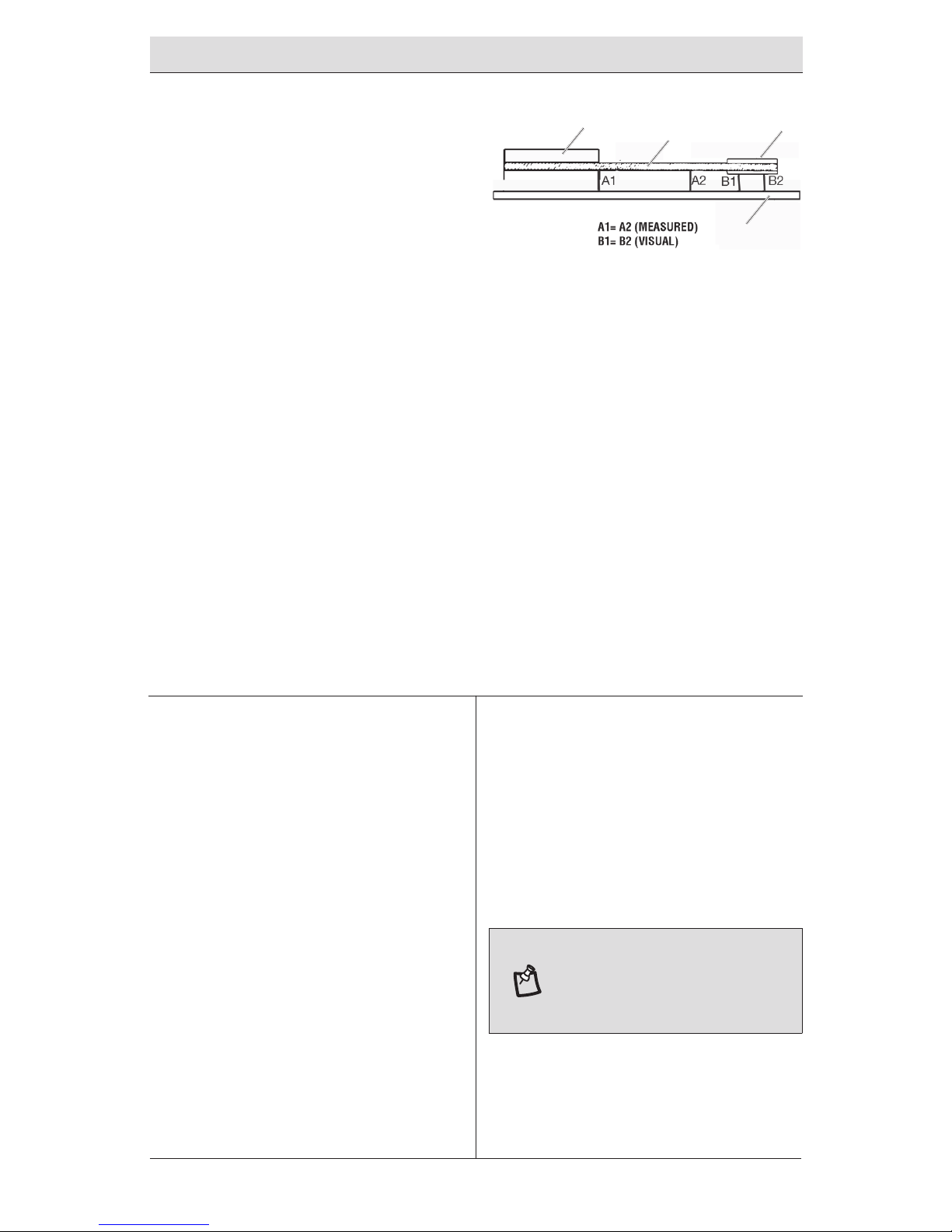
6
Motor Pulley/Flywheel
Alignment (Figure 8)
The air compressor ywheel and motor pulley
must be in-line (in the same plane) within
1/16” (1.6 mm) to assure belt retention
within ywheel belt grooves. To check
alignment, perform the following steps:
1. Turn air compressor off, lock out
the power supply, and relieve all air
pressure from the air tank.
2. Remove belt guard.
3. Place a straightedge (S) against the
outside of the ywheel (P) and the
motor drive pulley (R).
4. Measure the distance between the edge
of the belt (Q) and the straightedge
at points A1 and A2 in gure. The
difference between measurements
should be no more than 1/16” (1.6 mm).
FIGURE 8
P
Q R
S
5. If the difference is greater than 1/16”
(1.6 mm) loosen the set screw holding
the motor drive pulley (R) to the shaft
and adjust the pulley’s position on the
shaft until the A1 and A2 measurements
are within 1/16” (1.6 mm) of each other.
6. Tighten the motor drive pulley set screw.
7. Visually inspect the motor drive pulley
to verify that it is perpendicular to the
drive motor shaft. Points B1 and B2 of
Figure should appear to be equal. If
they are not, loosen the setscrew of the
motor drive pulley and equalize B1 and
B2, using care not to disturb the belt
alignment performed in step 2.
8. Retighten the motor drive pulley
setscrew. Torque to 145–165 in lbs
(16.4–20.3Nm).
9. Reinstall belt guard.
7
Air Compressor Pump
Intake and Exhaust Valves
Once a year bring the compressor to a
service center. and have a Trained Service
Technician check the air compressor pump
intake and exhaust valves.
8
INSPECT AIR LINES AND
FITTINGS FOR LEAKS
1. Turn air compressor off, lock out
the power supply, and relieve all air
pressure from the air tank.
2. Apply a soap solution to all air line
ttings and connections/piping.
3. Correct any leaks found.
NOTICE: Even minor leaks can
cause the air compressor to
overwork, resulting in premature
breakdown or inadequate
performance.
Maintenance (continued)
Page 16
16
9
Air compressor Head Bolts
- Torquing
The air compressor pump head bolts should
be kept properly torqued. Check the torques
of the head bolts after the rst ve hours of
operation.
Torque to 14-16 ft-lbs (19–21.7 Nm).
10
Additional Service
Disassembly or service of the air compressor
beyond what is covered in this manual is
not recommended. If additional service is
required, contact 1-888-43-HUSKY for further
assistance.
Maintenance (continued)
Storage
Before you store the air compressor, make sure you do the following:
1. Review the Maintenance section on the preceding pages and perform scheduled
maintenance as necessary.
2. Drain water from air tank. See To Drain Tank under Operation.
WARNING: Water will condense
in the air tank. If not drained,
water will corrode and weaken
the air tank causing a risk of air
tank rupture.
Troubleshooting
Problem Possible Cause Solution
Compressor does
not run.
Tank has insufcient
pressure.
When the tank pressure drops, the
compressor will turn on to cut-in
pressure.
No electrical power. Verify wiring connection inside
pressure switch and terminal box
area.
Blown stop/house fuse. Replace the shop/house fuse.
Tripped shop/home
breaker.
Reset the shop/home breaker and
determine the underlying cause.
Thermal overload is open. Place the Auto/Off switch in the
“Off” position.
Allow the motor to cool.
Depress the red reset button on
the motor.
Place the Auto/Off switch in the
“Auto” postion to restart the
motor.
Page 17
17
HUSKYTOOLS.COM
Please contact 1-888-43-HUSKY for further assistance.
pts-205109-051012
Loss of power or
overheating.
Verify wiring.
NOTE: Long lengths of electrical
wiring could cause power loss to
the motor.
Pressure switch is bad. Replace the pressure switch.
Motor hums but
does not run or
runs slowly.
Low voltage. Check voltage with a voltmeter.
Loose electrical
connections.
Verify wiring connection inside
pressure switch and terminal box
area.
Shorted or open motor
winding.
Bring the compressor to a service
center.
Defective check valve or
unloader.
Bring the compressor to a service
center.
Fuses blow or
circuit breaker trips
repeatedly.
Incorrect fuse size, circuit
overload.
Verify proper fuse size is being
used.
Use time-delay fuses.
Disconnect other electrical
appliances from the circuit or
operate compressor on its own
branch circuit.
Loose electrical
connections.
Verify wiring connection inside
pressure switch and terminal box
area.
Defective check valve or
unloader.
Bring the compressor to a service
center.
Knocking Noise
Loose pulley. Tighten pulley set screw.
Loose ywheel. Tighten ywheel screw.
Compressor mounting
screws loose.
Tighten mounting screws.
Loose belt. Check belt tension.
Carbon build-up in pump. Bring the compressor to a service
center.
Belt too tight. Check belt tension.
Excessive belt wear
Loose belt. Check belt tension.
Tight belt. Check belt tension.
Loose pulley. Bring the compressor to a service
center.
Pulley misalignment. Align pulley/ywheel.
Squealing sound
Compressor pump has no
oil.
Check pump oil
Loose belt. Check belt tension.
Restricted air
intake
Dirty air lter. Clean or replace air lter.
Troubleshooting (continued)
Page 18

18
Troubleshooting (continued)
Oil and/or moisture
in tank and/or air
lines
Water condensation
Oil blow-by in pump
It is normal for oil lube air
compressor pumps to release some
oil into the tank and air lines. Air
compressors will also generate
water condensation that will form
in the tank and air lines. Install
water and oil lter traps when
needed. The Typical Compressed
Air Distribution System provides
a guideline. Contact a call Husky
Customer Service for more
information.
IMPORTANT: If the tank or air
lines have excessive water and/
or oil, bring the compressor to a
service center.
Page 19
19
HUSKYTOOLS.COM
Please contact 1-888-43-HUSKY for further assistance.
pts-205109-051012
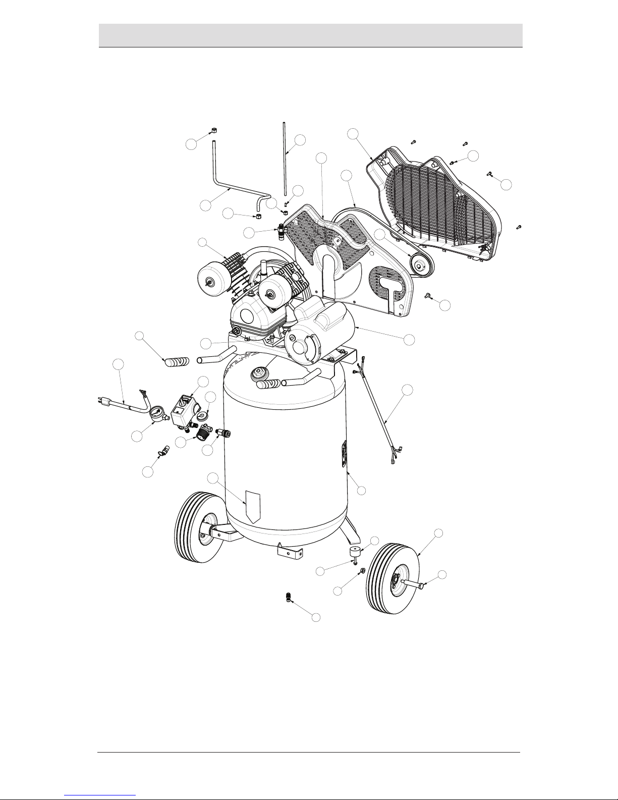
Exploded View
1
2
3
4
5
6
7
8
9
12
13
14
22
23
24
25
26
27
28
30
31
32
33
35
36
58
55
16
15
18
19
20
21
24
Page 20

20
ITEM NUMBER PART NUMBER QUANTITY DESCRIPTION
1 E106042 1 TANK 30G VP BLACK
2 A17038 1 VALVE DRAIN .25NPT
3 E105834 2 BUMPER RUBBER FOOT
4 NA 2 .250-20 X 1.50 SCREW
5 E105775 2 WHEEL 10IN PNEUMATIC
6 D23574 2 BOLT SHOULDER .375-16 X 3.40
7 NA 2 NUT .375-16 HEX
8 E105643 2 GRIP HANDLE
9 E106043 1 PUMP V-TWIN
9B D23190 2 FILTER
12 E105511 1 PULLEY A-SEC 3.75OD X 5/8" BORE
13 E106044 1 MOTOR 115 VOLT
13A E106035 1 START CAPACITOR
13B E106036 1 RUN CAPACITOR
13C E106037 1 START CAPACITOR COVER
13D E106038 1 RUN CAPACITOR COVER
14 E105543 1 SWITCH PRESS 4 PORT 105-135 PSI
15 TIA-4150 1 VALVE SAFETY
16 SUDL-431-2 1 ASSY CORD POWER
18 E105636 1 REGULATOR
19 D23004 1 GAUGE .125 BACKMOUNT
20 E105635 1 QUICK CONNECT
21 A14993 1 GAUGE .25 SIDE MOUNT
22 E105545 1 TUBE OUTLET
23 E105549 1 VALVE CHECK
24 SSP-7813 2 ASSY NUT SLEEVE 3/8
25 E106045 1 BELTGUARD INNER
26 E106046 1 BELTGUARD OUTER
27 E105512 1 BELT A-SECTION A44
28 NA 3 SCREW .250-20 X .75
30 E105548 1 TUBE PRESS REL
31 5130039-00 1 BRASS INSERT
32 SSP-7811 1 ASSY NUT SLEEVE 1/4
33 E105537 1 CORD INTERCONNECT
35 NA 8 SCREW 5/16-18 X .75
36 NA 4 SCREW #10-14 PLASTITE
Parts List
Page 21

21
HUSKYTOOLS.COM
Please contact 1-888-43-HUSKY for further assistance.
pts-205109-051012
NOT SHOWN N008801 1 LABEL WARNING
NOT SHOWN N008806 1 LABEL HOT SURFACE LABEL
55 LA-2832 1 LABEL DRAIN TANK
58 NA 1 ASSY FASTENER
Parts List (Continued)
Page 22

Questions, problems, missing parts? Before returning to the store call
Husky Customer Service
8 a.m. - 6 p.m., EST, Monday-Friday
1-888-43-HUSKY
HUSKYTOOLS.COM
Retain this manual for future use.
Document Number: E105758
Page 23

Page 24

Page 25

Article # 723883
Modèle # C301H
GUIDE D’UTILISATION
ET D’ENTRETIEN
COMPRESSEUR D’AIR PORTATIF
DE 114 LITRES (30 GALLONS)
Questions, problèmes, pièces
manquantes?
Avant de retourner au magasin,
veuillez communiquer avec le
service à la clientèle Husky entre
8h00 et 18h00, HNE, du lundi au
vendredi au
1-888-43-HUSKY
HUSKYTOOLS.COM
MERCI
Nous vous remercions d’avoir fait conance à Husky en achetant ce compresseur d’air portatif de 114
litres (30 gallons). Nous nous efforçons en permanence de créer des produits de qualité conçus pour
perfectionner votre maison. Vous pouvez visiter notre site en ligne pour consulter notre gamme complète
de produits pour vos besoins de rénovation résidentielle. Merci d’avoir choisi Husky!
Page 26

2
Table des matières
Consignes de sécurité ........................ 2
Sécurité de l’aire de travail .............2
Sécurité de l’utilisateur ..................3
Transport ........................................3
Sécurité du compresseur d’air et des
outils pneumatiques .......................4
Sécurité électrique ..........................4
Sécurité électrique
(Rallonges) .....................................5
Sécurité électrique
(Branchements électriques) ............5
Sécurité électrique
(Vitesse et câblage) ........................5
Sécurité électrique
(Instructions de mise à la terre) ......6
Garantie .............................................. 6
Caractéristiques.................................. 7
Cycle de service .................................. 7
Contenu de l’emballage ..................... 7
Assemblage ...................................... 10
Utilisation ......................................... 11
Entretien ........................................... 13
Entreposage ..................................... 18
Dépannage ....................................... 18
Consignes de sécurité
Ce guide contient des informations qu’il vous
est important de connaître et de comprendre.
Ces informations ont trait à VOTRE SÉCURITÉ
et à la PRÉVENTION DES PROBLÈMES
D’ÉQUIPEMENT. Pour vous aider à identier
ces informations, nous utilisons les symboles
ci-dessous. Veuillez lire ce guide et prêter
particulièrement attention à ces symboles.
DANGER : Indique une situation
imminément dangereuse qui, si
elle n’est pas évitée, résultera
en mort d’homme ou des
blessures graves.
MISE EN GARDE : Indique
une situation potentiellement
dangereuse qui, si elle n’est
pas évitée, pourrait résulter
en mort d’homme ou des
blessures graves.
ATTENTION : Indique une
situation potentiellement
dangereuse qui, si elle n’est
pas évitée, pourrait résulter
en blessures mineures ou
modérées.
AVIS : Indique une pratique non
associée à des blessures, qui,
si elle n’est pas évitée, pourrait
résulter en des dommages
matériels.
SÉCURITÉ DE L’AIRE DE TRAVAIL
1. Gardez l’aire de travail propre et bien
éclairée. Faites en sorte que les sols ne
soient pas glissants du fait de cire ou de
poussière.
2.
N’utilisez pas d’outil
électrique en présence
de vapeurs explosives,
comme celles dégagées par des liquides,
des gaz ou des poussières inammables.
Les outils électriques produisent des
étincelles qui peuvent mettre le feu à la
poussière ou aux vapeurs. Éloignez les
curieux, les enfants et les visiteurs
pendant que vous utilisez des outils. Une
distraction peut vous faire perdre le
contrôle de l’outil.
3. Utilisez le compresseur d’air dans un
espace ouvert à une distance d’au
moins 0,5 m (18 po) de tout mur ou
objet qui pourrait limiter le ux d’air
frais aux orices de ventilation.
4.
Débranchez toujours l’alimentation
en air et l’alimentation en courant
électrique avant tout réglage,
entretien d’un outil ou lorsque l’outil n’est
pas utilisé.
5. TCe compresseur/pompe n’est
pas équipé(e) et ne devrait pas
être utilisé(e) pour fournir de
l’air respirable. Des équipements
Page 27

3
HUSKYTOOLS.COM
Veuillez composer le 1 888 43-HUSKY pour
une assistance supplémentaire.
pts-205109-051012
supplémentaires seraient nécessaires
pour ltrer et purier l’air correctement
an de satisfaire les critères minimaux
de l’air respirable de Grade D tels que
décrits dans la norme Commodity
Specication G 7.1 établie par la
Compressed Gas Association - 1966,
OSHA 29 CF9 1910.134. Compressed
Gas Association, 4221 Walney Road,
Fifth Floor, Chantilly, VA 20151-2923,
(703) 788-2700, www.cganet.com. Un
équipement supplémentaire de ce type
n’a pas été étudié et aucune implication
d’utilisation correcte pour de l’air
respirable n’est voulue ou sousentendue.
SÉCURITÉ DE L’UTILISATEUR
MISE EN GARDE : L’utilisation
de n’importe quel outil électrique
peut entraîner la projection
d’objets étrangers dans les
yeux, ce qui peut occasionner
des blessures oculaires graves.
Avant de commencer l’utilisation,
mettez toujours des lunettes
protectrices, des lunettes de
sécurité munies d’écrans latéraux
ou un masque protecteur
complet si nécessaire. Utilisez
toujours une protection oculaire
portant une étiquette indiquant
qu’elle est conforme à la norme
ANSI Z87.1.
MISE EN GARDE : Ce produit
contient des produits chimiques,
reconnus par l’état de Californie
comme pouvant causer le cancer,
des anomalies congénitales ou
d’autres dommages aux fonctions
reproductrices. Lavez vos mains
après avoir manipulé l’outil.
1.
Portez un équipement
de protection. Portez
toujours des lunettes
de protection avec des écrans latéraux
lorsque vous utilisez des outils
électriques. Vous devez porter un
masque anti-poussière, des chaussures
de sécurité anti-dérapantes, un casque
de sécurité ou des protecteurs
auriculaires en fonction des conditions.
2.
Demeurez vigilant lorsque vous
utilisez un outil électrique.
N’utilisez pas l’outil si vous
êtes fatigué ou lorsque vous avez
consommé de la drogue, de l’alcool ou des
médicaments.
3.
Évitez de porter des
vêtements amples ou
des bijoux. Attachez
les cheveux longs. Gardez les cheveux,
les vêtements et les gants à l’écart des
pièces mobiles. Les vêtements amples,
bijoux ou cheveux longs pourraient se
prendre dans les pièces mobiles.
4. Campez fermement vos pieds au sol et
gardez votre équilibre en tout temps.
Un appui stable et un bon équilibre
permettent de mieux contrôler l’outil
dans des situations inattendues.
5. N’utilisez pas l’outil sur une échelle ou
sur une surface instable.
6.
Ne touchez jamais les pièces en
métal exposées sur le
compresseur pendant ou
immédiatement après utilisation. Le
compresseur restera chaud pendant
plusieurs minutes après son utilisation.
Ne touchez à rien derrière les écrans
protecteurs et ne tentez aucun entretien
sans avoir laissé à l’appareil le temps de
refroidir.
8.
Le compresseur est trop lourd
pour être soulevé par une seule
personne. Faites-vous aider par
d’autres personnes avant de soulever.
TRANSPORT
1. Placez toujours le compresseur
sur un petit tapis de protection
lors de son transport pour
protéger le véhicule contre tout
dommage dû à des fuites. Retirez le
compresseur du véhicule immédiatement
une fois arrivé à destination.
2. Transportez et entreposez toujours
l’appareil dans la position verticale.
Consignes de sécurité (suite)
Page 28

4
SÉCURITÉ DU COMPRESSEUR
D’AIR ET DES OUTILS
PNEUMATIQUES
MISE EN GARDE : Ne tentez pas
de modier cet outil ou de créer
des accessoires dont l’utilisation
n’est pas recommandée avec
cet outil. Une telle altération
ou modication est considérée
comme une utilisation
inappropriée et risque de créer
une situation dangereuse pouvant
entraîner des blessures graves.
ATTENTION : N’utilisez pas
l’outil dans un environnement
qui est poussiéreux ou contaminé
d’une façon quelconque. Toute
utilisation du compresseur d’air
dans un environnement de ce type
pourrait endommager l’appareil.
1. Gardez les compresseurs aussi
éloignés que possible de la zone de
pulvérisation, soit à 4,5 m (15 pi) au
moins de la zone de pulvérisation et de
toutes vapeurs explosives.
2.
Risque d’éclatement. Ne réglez
pas le régulateur d’une manière
telle que la pression de sortie
soit supérieure à la pression maximale
indiquée sur l’accessoire. Ne l’utilisez pas
à une pression supérieure à la pression
maximale homologuée de ce compresseur.
3. Si branché sur un circuit protégé par des
fusibles, utilisez des fusibles temporisés
avec ce produit.
4.
Pour réduire le risque de choc
électrique, ne l’exposez pas à la
pluie. Entreposez-le à l’intérieur.
5. Assurez-vous que le tuyau exible
n’est pas obstrué et ne présente aucun
accroc. Des tuyaux exibles emmêlés ou
enchevêtrés peuvent vous faire perdre
l’équilibre ou tomber et pourraient être
endommagés.
6. Utilisez le compresseur d’air seulement
aux ns pour lesquelles il a été conçu.
N’altérez pas et ne modiez pas l’appareil
par rapport à sa conception ou sa fonction
originale. Ne soudez ni ne percez jamais
des trous dans le réservoir d’air.
7. Ne laissez jamais l’outil sans surveillance
avec le tuyau exible d’air raccordé.
8. N’utilisez pas cet outil s’il ne présente pas
une étiquette de mise en garde lisible.
9. Ne continuez pas à utiliser un outil ou un
tuyau exible avec une fuite d’air ou qui
ne fonctionne pas correctement.
10. Ne tentez pas de tirer ou de porter le
compresseur d’air par le tuyau exible.
11. Votre outil peut consommer plus d’air que
ce compresseur d’air est capable de fournir.
12. Ne dirigez jamais un jet d’air comprimé
vers une personne ou un animal.
13. Protégez vos poumons. Portez un
masque protecteur ou un masque
anti-poussière si l’utilisation est
poussiéreuse.
14. N’utilisez pas ce compresseur d’air
pour pulvériser des produits chimiques.
Vos poumons peuvent être abîmés par
l’inhalation de vapeurs toxiques. Porter un
masque ltrant peut s’avérer nécessaire
dans les environnements poussiéreux ou
lors de la pulvérisation de peinture.
SÉCURITÉ ÉLECTRIQUE
1. Évitez tout contact corporel avec les
surfaces mises à la terre, telles que
conduites, radiateurs, cuisinières et
réfrigérateurs. Le risque de choc électrique
est accru si votre corps est mis à la terre.
2. N’exposez pas les outils électriques à
la pluie ou à des conditions mouillées.
Les risques de choc électrique sont plus
élevés si de l’eau s’inltre dans un outil
électrique.
3. Remplacez tout cordon/câble endommagé
immédiatement. Les cordons/câbles
endommagés augmentent le risque de
choc électrique.
Consignes de sécurité (suite)
Page 29

5
HUSKYTOOLS.COM
Veuillez composer le 1 888 43-HUSKY pour
une assistance supplémentaire.
pts-205109-051012
SÉCURITÉ ÉLECTRIQUE (RALLONGES)
MISE EN GARDE : Maintenez
la rallonge à l’écart de l’aire
de travail. Positionnez la
rallonge de sorte qu’elle ne
puisse se prendre dans du bois
d’œuvre, des outils ou toute
autre obstruction pendant que
vous travaillez avec un outil
électrique. Ne pas respecter
ces consignes pourrait
entraîner des blessures graves.
MISE EN GARDE : Inspectez
les rallonges avant chaque
utilisation. Si elles sont
endommagées, remplacez-les
immédiatement. N’utilisez
jamais un compresseur d’air
avec un cordon endommagé
puisque toucher la partie
endommagée pourrait causer
un choc électrique et ainsi
provoquer des blessures graves.
MISE EN GARDE : Mal brancher
le conducteur de mise à la terre
de l’équipement peut créer un
risque de choc électrique.
1. Utilisez uniquement des rallonges
électriques à trois ls, dotées d’une
che à trois broches et d’une prise à
trois broches qui accepte la che du
compresseur d’air. Assurez-vous que la
rallonge électrique est en bon état.
2. Lorsque vous utilisez le compresseur d’air
à une grande distance de la source de
courant électrique, utilisez une rallonge
d’un calibre sufsant pour transporter
le courant que le compresseur tirera.
L’utilisation d’une rallonge de calibre trop
faible entraînera une chute de tension
sectorielle se traduisant par une perte de
puissance et une surchauffe de l’appareil.
Servez-vous de la charte suivante pour
déterminer la taille minimale de l
nécessaire dans la rallonge.
3. Utilisez seulement 30 m (100 pi) ou moins
de cordons à gaine ronde homologués par
Underwriter’s Laboratories (UL).
Consignes de sécurité (suite)
4. Lors de l’utilisation d’un outil électrique
à l’extérieur, servez-vous d’une rallonge
d’extérieur portant la mention «W-A» ou
«W». Ces rallonges sont homologuées
pour une utilisation en extérieur et
réduisent le risque de choc électrique.
REMARQUE: Utilisez des tuyaux
exibles plus longs pour l’air plutôt
que des longues rallonges. Votre
compresseur d’air fonctionnera
mieux et durera plus longtemps.
SÉCURITÉ ÉLECTRIQUE
(BRANCHEMENTS ÉLECTRIQUES)
1. Ce compresseur d’air est alimenté par
un moteur électrique construit avec
précision. Il doit être branché sur un circuit
d’alimentation de 120 volts, 60 Hz, c.a.
uniquement (courant résidentiel normal).
2. N’utilisez pas cet outil sur du courant
continu (c.c.). Une chute de tension
importante entraînera une perte de
puissance et le moteur surchauffera. Si le
compresseur d’air ne fonctionne pas une
fois branché dans une prise de courant,
re-vériez la source de courant électrique.
SÉCURITÉ ÉLECTRIQUE
(VITESSE ET CÂBLAGE)
1. La vitesse à vide du moteur électrique
est fonction du modèle et de ses
caractéristiques. La vitesse du moteur
n’est pas constante et diminue avec une
charge ou une tension plus basse. Pour
la tension, le câblage dans un atelier
est aussi important que la puissance
nominale en chevaux-vapeur du moteur.
2. Une ligne conçue pour l’éclairage ne
peut pas correctement alimenter le
moteur d’un outil électrique. Un câble
sufsamment gros pour une courte
Intensité nominale (sur la plaque
signalétique du compresseur d’air)
0-2.0
2.1-
3.4
3.5-
5.0
5.1-
7.0
7.1-
12.0
12.1-
16.0
Longueur du cordon
25´ 16 16 16 16 14 14
50´ 16 16 16 14 14 12
100´ 16 16 14 12 10 -
Utilisé sur un circuit de calibre 12 - 20 ampères..
Page 30

6
distance sera trop léger pour une plus
grande distance. Une ligne qui peut
alimenter un outil électrique peut ne pas
pouvoir en alimenter deux ou trois.
SÉCURITÉ ÉLECTRIQUE
(INSTRUCTIONS DE MISE À LA TERRE)
1. Ce produit doit être mis à la terre. En
cas de court-circuit, la mise à la terre
réduit le risque de choc électrique en
fournissant un l d’échappement au
courant électrique. Ce compresseur d’air
est équipé d’un cordon d’alimentation
électrique comportant un conducteur
de mise à la terre de l’équipement et
une che de mise à la terre. La che de
mise à la terre doit être branchée dans
une prise de courant qui lui correspond,
correctement installée et mise à la
terre conformément aux codes et aux
règlements locaux.
Garantie
GARANTIE LIMITÉE DE DEUX ANS SUR LES COMPRESSEURS
D’AIR HUSKY
Cette garantie couvre, pendant une période de deux ans à partir de la date d’achat, tous les
défauts de fabrication ou de matériaux qui pourraient affecter ce compresseur d’air Husky. La
présente garantie vise uniquement ce modèle de compresseur d’air. Les garanties couvrant
d’autres produits HUSKY peuvent être différentes.
Cette garantie ne s’applique qu’à l’acheteur original et n’est pas transférable. La présente
garantie ne couvre pas l’usure normale ni les cas de mauvais fonctionnement, les pannes ou
les défauts résultant d’une mauvaise utilisation, d’un usage abusif, d’une négligence, d’une
altération, d’une modication ou d’une réparation effectuée par une personne ou un centre
Consignes de sécurité (suite)
2. Consultez un électricien qualié ou un
réparateur si vous ne comprenez pas
les instructions de mise à la terre ou si
vous n’êtes pas certain que l’appareil est
correctement mis à la terre. Ne modiez
pas la che qui vous est fournie. Si vous
n’arrivez pas à l’insérer dans la prise de
courant, faites installer la prise de courant
adéquate par un électricien qualié.
3. Ce produit doit être utilisé sur une tension
nominale de 120 V avec une che de mise
à la terre comme illustré dans la gure 1.
Ne branchez le produit que dans une prise
de courant ayant la même conguration
que la che. N’utilisez pas d’adaptateur
avec ce produit.
MISE À LA TERRE BROCHES
120V PRISE DE TERRE
FIGURE 1
AVERTISSEMENT : Une
mauvaise installation
de la che de mise à la
terre peut entraîner un
risque de choc électrique.
Lorsqu’une réparation ou un
remplacement du cordon ou
de la che d’alimentation
électrique est nécessaire, ne
connectez pas le l de mise à
la terre sur aucune des bornes
à lame plate. Le l dont la
surface externe de la gaine
isolante est verte, avec ou
sans rayures jaunes, est le l
de mise à la terre.
Page 31

7
HUSKYTOOLS.COM
Veuillez composer le 1 888 43-HUSKY pour
une assistance supplémentaire.
pts-205109-051012
autre qu’un centre de service autorisé à réparer les compresseurs d’air de la marque Husky.
Les consommables tels que les brosses du moteur, les joints, etc., ne sont pas couverts par
la présente garantie. Cette garantie ne couvre pas ce compresseur s’il est utilisé dans des
applications industrielles ou loué. Husky n’offre aucune garantie, déclaration ou promesse
quant à la qualité ou au rendement de ses compresseurs d’air autre que celles spéciquement
stipulées dans la présente garantie.
AUTRES RESTRICTIONS
Dans les limites de la loi applicable, toutes les garanties implicites, y compris les garanties de
qualité marchande ou d’adaptation à un usage particulier, sont expressément désavouées.
Toutes les garanties implicites, y compris les garanties de qualité marchande ou d’adaptation
à un usage particulier, qui ne peuvent faire partie d’une clause d’exonération en vertu de la
loi d’un état sont limitées à deux ans à partir de la date d’achat. Husky n’assume aucune
responsabilité quant aux dommages directs, indirects, accessoires, particuliers ou consécutifs.
Si ce compresseur d’air est utilisé à des ns commerciales, la garantie est limitée à quatrevingt dix (90) jours à compter de la date d’achat. Certains états et provinces ne permettent
pas les restrictions quant à la durée d’une garantie implicite, ni l’exclusion ou la restriction
des dommages indirects ou accessoires. Par conséquent, il se pourrait que les restrictions
mentionnées ci-dessus ne s’applique pas à votre cas. En vertu de la présente garantie, vous
bénéciez de droits juridiques particuliers; toutefois, d’autres droits peuvent également
s’appliquer, selon l’État où vous résidez.
Veuillez communiquer avec le service à la clientèle au 1 888-43-HUSKY ou visiter le site www.
huskytools.com.
Caractéristiques
COMPRESSEUR D’AIR
Puissance de
fonctionnement en
cheval-vapeur
1,6 CV
Capacité du réservoir d’air 114 litres (30 gal)
Pression d’air 931 kPa (135 PSI) max
Débit d’air 0,18 M3/MIN (6,2 PI3/MIN) À 276 KPA (40 PSI)
0,15 M3/MIN (5,3 PI3/MIN) À 620 KPA (90 PSI)
Lubrication Huile de graissage
Entrée
240 V, 60 Hz, c.a. monophasé
uniquement, 15 A
Spécication minimum du
circuit de dérivation
15A
Type de fusible Temporisé
Poids net 67kg (148 lbs).
Cycle de service
La pompe du compresseur d’air peut fonctionner en continu. Toutefois, pour prolonger la vie
de service de votre compresseur d’air, il est recommandé de maintenir un cycle de service
moyen de 50 %, à savoir la pompe du compresseur d’air ne devrait pas fonctionner plus de 30
minutes pour chaque heure donnée.
Garantie (suite)
Page 32

8
Contenu de l’emballage
Familiarisez-vous avec ces commandes avant d’utiliser l’appareil (Figure 2)
Pièce Description
A
Interrupteur Auto(I)/Arrêt(0) : Mettez cet interrupteur dans la position «Auto (I)»
pour fournir une alimentation électrique continue au pressostat et sur la position
«Arrêt (0)» pour couper l’alimentation électrique à la n de chaque utilisation.
B
Pressostat : Le pressostat démarre automatiquement le moteur quand la pression
dans le réservoir d’air tombe en dessous de la pression d’«intervention» pré-établie
en usine. Il arrête le moteur quand la pression dans le réservoir d’air atteint la
pression de «coupure» pré-établie en usine.
C
Soupape de sûreté : Si le pressostat n’éteint pas le compresseur d’air à la pression
de «coupure» pré-établie en usine, la soupape de sûreté protégera contre les hautes
pressions en «ressortant» à sa pression seuil pré-établie en usine (légèrement plus
élevée que la pression de «coupure» du pressostat).
D
Manomètre du réservoir : Le manomètre du réservoir indique la pression de l’air
stocké dans le réservoir.
A
B
C
D
E
F
G
H
I
J
K
L
M
N
O
Q
P
Page 33

9
HUSKYTOOLS.COM
Veuillez composer le 1 888 43-HUSKY pour
une assistance supplémentaire.
pts-205109-051012
Pièce Description
E
Pompe du compresseur d’air : Comprime l’air dans le réservoir d’air. Aucun air
comprimé n’est disponible tant que le compresseur n’a pas augmenté la pression de
l’air dans le réservoir au-dessus de la pression requise à la sortie d’air.
F
Robinet de purge : Le robinet de purge se trouve à la base du réservoir d’air et sert
à éliminer la condensation à la n de chaque utilisation.
G
Clapet anti-retour : Quand le compresseur d’air fonctionne, le clapet anti-retour
est «ouvert» ce qui permet à l’air comprimé d’entrer dans le réservoir d’air. Quand
le compresseur d’air parvient à la pression de «coupure», le clapet anti-retour «se
ferme» ce qui permet de maintenir la pression de l’air dans le réservoir d’air.
H
Clapet de décharge : Le clapet de décharge se trouve à côté du pressostat; il sert
à libérer automatiquement de l’air comprimé au niveau de la tête du compresseur et
du tube de sortie lorsque le compresseur d’air atteint la pression de «coupure» ou est
éteint. Le clapet de décharge permet au moteur de redémarrer librement. Lorsque le
moteur s’arrête de fonctionner, on peut entendre l’air s’échapper par ce clapet pendant
quelques secondes. Aucune fuite d’air ne devrait être entendue lorsque le moteur
fonctionne ou une fois que l’appareil a atteint la pression de «coupure».
I
Réinitialisation de la protection contre la surcharge du moteur : Ce moteur
est doté d’une protection manuelle contre les surcharges thermiques. Si le moteur
surchauffe pour une raison quelconque, la protection contre la surcharge éteindra
le moteur. Il faut laisser refroidir le moteur avant de pouvoir le redémarrer. Pour le
redémarrer :
1. Mettez l’interrupteur Auto/Arrêt en position «Arrêt».
2. Laissez le moteur refroidir.
3. Appuyez sur le bouton rouge de réinitialisation situé sur le moteur.
4. Mettez l’interrupteur Auto/Arrêt en position «Auto» pour redémarrer le moteur.
J Pieds du compresseur
K Garde-courroie
L Remplissage de l’huile de la pompe
M Vidange de l’huile de la pompe
N Regard en verre du niveau d’huile de la pompe
O Moteur
P Manomètre de régulation
Q Roues
Contenu de l’emballage (suite)
Page 34

10
Assemblage
1
Emplacement du compresseur d’air
1. Installez le compresseur d’air dans un espace propre, sec et bien aéré.
2. Installez le compresseur d’air à une distance d’au moins 0,5 m (18 po) de tout mur ou
toute autre obstruction qui gênerait le ux d’air.
3. Installez le compresseur d’air aussi près que possible d’une source d’alimentation
électrique pour éviter d’avoir à utiliser des longueurs importantes de l électrique.
REMARQUE : De grandes longueurs de l électrique pourraient résulter en une perte
de puissance arrivant au moteur.
4. Le ltre à air doit être conservé exempt de toute obstruction qui pourrait réduire le
débit d’air arrivant au compresseur d’air.
2
Rodage de la pompe
AVIS : Risque de dommages matériels. Manquer de suivre à la lettre les
consignes de rodage ci-dessous peut causer des dommages matériels.
Cette procédure est requise avant de mettre en service le compresseur d’air et si le clapet antiretour ou la pompe entière du compresseur ont été remplacés.
1. Assurez-vous que l’interrupteur Auto/Arrêt (A) est en position «Arrêt».
2. Vériez le niveau d’huile dans la pompe. Consultez le paragraphe Huile dans la section
Entretien pour les instructions.
3. Re-vériez le câblage. Vériez que tous les ls sont solidement et sécuritairement
raccordés au niveau de toutes les connexions de bornes. Vériez que tous les contacts se
déplacent librement et ne sont pas bouchés.
4. Ouvrez le robinet de purge (F) complètement pour laisser l’air s’échapper et empêcher
l’air de monter en pression dans le réservoir pendant la période de rodage.
5. Mettez l’interrupteur Auto/Arrêt (A) en position «Auto». Le compresseur démarrera.
6. Faites fonctionner le compresseur d’air pendant 20 minutes. Vériez que le robinet de
purge et toutes les canalisations d’air sont ouverts de sorte que la montée en pression de
l’air soit minimale dans le réservoir.
7. Inspectez tous les raccords des canalisations d’air et toutes les connexions/conduites à la
recherche de fuites d’air en appliquant une solution savonneuse. Corrigez au besoin.
AVIS : Des fuites mineures peuvent entraîner un surmenage du compresseur d’air,
et résulter dans des pannes prématurées ou un rendement inadéquat.
8. Inspectez pour rechercher un excès de vibration. Re-réglez ou calez les pieds du
compresseur d’air au besoin.
9. Au bout de 20 minutes, fermez le robinet de purge. Le réservoir d’air se remplira jusqu’à
atteindre la pression de «coupure» et le moteur s’arrêtera.
Le compresseur d’air est désormais prêt à être utilisé.
Page 35

11
HUSKYTOOLS.COM
Veuillez composer le 1 888 43-HUSKY pour
une assistance supplémentaire.
pts-205109-051012
Utilisation
1
PURGE DU RÉSERVOIR
(FIGURE 2, 4)
MISE EN GARDE : Risque de
fonctionnement non sécuritaire.
Les réservoirs d’air contiennent
de l’air à haute pression.
Gardez le visage et les autres
parties du corps éloignés de
la sortie de purge. Utilisez
des protections oculaires
[ANSI Z87.1 (CAN/ACN Z94.3)]
lorsque vous purgez car des
débris peuvent être projetés
dans votre visage.
MISE EN GARDE : Risque
associé au bruit. Utilisez des
protection auriculaire (ANSI
S12.6 (S3.19) car l’écoulement
d’air émet un bruit fort
pendant la purge.
MISE EN GARDE : Risque
d’éclatement. De l’eau
condensera dans le réservoir
d’air. Si elle n’est pas
éliminée, l’eau corrodera et
affaiblira le réservoir d’air
créant ainsi un risque de
rupture du réservoir d’air.
AVIS : Risque de dommages
matériels. L’eau purgée du
réservoir d’air peut contenir de
l’huile et de la rouille qui peuvent
causer des taches.
F
FIGURE 4
AVIS : Tous les systèmes d’air
comprimé génèrent des condensats
qui s’accumulent dans tout point
de purge (par exemple, réservoirs,
ltres, refroidisseurs, séchoirs). Ce
condensat contient de l’huile de
graissage et/ou des substances
qui peuvent être sujettes à des
réglementations et par conséquent
il doit être éliminé conformément
aux réglementations et aux
législations locales, régionales et
nationales.
AVIS : Si le robinet de purge
est bouché, relâchez toute la
pression de l’air. Le robinet peut
alors être retiré, nettoyé puis
réinstallé.
1. Réglez l’interrupteur Auto/Arrêt (A,
Figure 2) sur «Arrêt».
2. Laissez s’échapper lentement l’air
du réservoir d’air et du système de
distribution d’air jusqu’à ce que la
pression dans le réservoir tombe à
environ 138 kPa (20 psi).
3. Purgez l’eau du réservoir d’air en
ouvrant le robinet de purge (F) en bas
du réservoir.
4. Une fois que toute l’eau a été éliminée,
fermez le robinet de purge. Le compresseur
d’air peut maintenant être entreposé.
Page 36

12
2
Vérication de la soupape
de sûreté (Figure 5)
DANGER : N’altérez pas la
soupape de sûreté. Les éléments
desserrés de ce dispositif
pourraient être projetés et vous
frapper. Manquer à respecter cette
mise en garde pourrait entraîner
mort d’homme ou des blessures
graves. La soupape de sûreté
libère automatiquement l’air
quand la pression du réservoir
dépasse le maximum pré-établi.
Vériez la soupape tous les jours
avant utilisation en tirant sur
l’anneau manuellement.
MISE EN GARDE : Si de l’air fuit
après le relâchement de l’anneau
de la soupape de sûreté ou si la
soupape est coincée, n’utilisez
pas le compresseur d’air tant que
la soupape de sûreté n’a pas été
remplacée. Utiliser le compresseur
d’air dans cet état pourrait
entraîner des blessures graves.
1. Réglez l’interrupteur Auto/Arrêt (A) sur
la position «Marche» et attendez que le
réservoir se remplisse. Le compresseur
s’éteint automatiquement lorsque la
pression atteint le maximum pré-établi.
2. Réglez l’interrupteur Auto/Arrêt (A) sur
«Arrêt».
3. Tirez l’anneau de la soupape de sûreté (C)
pendant 20 secondes pour libérer l’air.
4. Relâchez l’anneau. L’air arrête de
s’échapper lorsque la pression est
d’environ 138 kPa (20 psi). Si l’air
continue à s’échapper une fois que
l’anneau de la soupape de sécurité a
été relâché, cessez toute utilisation du
compresseur et faites-le réparer avant
de l’utiliser à nouveau.
3
Avant chaque démarrage
(Figure 5)
MISE EN GARDE : Risque
d’utilisation non sécuritaire.
Saisissez fermement d’une
main le tuyau exible d’air
lorsque vous l’installez ou le
débranchez pour l’empêcher
de fouetter.
MISE EN GARDE : Risque
d’utilisation non sécuritaire.
N’utilisez pas d’accessoires
endommagés ou usés.
MISE EN GARDE : Risque
d’éclatement. Une pression
trop élevée peut créer
un risque dangereux
d’éclatement. Vériez la
pression maximale nominale
du fabricant pour les
outils pneumatiques et les
accessoires. La pression de
sortie du régulateur ne doit
jamais dépasser la pression
nominale maximum.
1. Réglez l’interrupteur Auto/Arrêt (A,
Figure 5) sur «Arrêt».
2. Fermez la bouche d’évacuation d’air.
3. Inspectez visuellement les canalisations
d’air et les raccords à la recherche de fuites.
4. Vériez la soupape de sûreté. Reportezvous au paragraphe Vérication de la
soupape de sûreté.
Utilisation (suite)
C
A
FIGURE 5
Page 37

13
HUSKYTOOLS.COM
Veuillez composer le 1 888 43-HUSKY pour
une assistance supplémentaire.
pts-205109-051012
ATTENTION : Risque
d’utilisation non sécuritaire.
L’air comprimé de l’appareil
peut contenir de l’eau de
condensation et un brouillard
d’huile. Ne pulvérisez pas de
l’air non ltré sur un objet
qui pourrait être endommagé
par l’humidité. Certains outils
pneumatiques et certains
accessoires peuvent requérir
de l’air ltré. Lisez le mode
d’emploi et les consignes pour
les outils pneumatiques et les
accessoires.
AVIS : Un régulateur DOIT
être installé lors de l’utilisation
d’accessoires homologués à
moins de 930 kPa (135 psi). Le
tuyau exible ou l’accessoire
nécessiteront un bouchon à
connexion rapide si la sortie
d’air est équipée d’une prise à
connexion rapide.
4
Comment démarrer
(Figure 2)
1. Mettez l’interrupteur Auto/Arrêt (A, Figure
2) sur «Auto» et laissez la pression monter
dans le réservoir. Le moteur s’arrêtera
lorsque la pression dans le réservoir atteint
la pression de «coupure».
2. Lors que le réservoir atteint la pression
de «coupure» ouvrez la vanne
d’évacuation d’air.
MISE EN GARDE : Risque
d’éclatement. Si vous
remarquez un bruit ou une
vibration inhabituel(le), arrêtez
immédiatement le compresseur
d’air et faites-le inspecter par
un technicien formé.
AVIS : Lors de l’utilisation
du régulateur et des autres
accessoires, consultez les
instructions des fabricants.
Utilisation (suite)
Entretien
ENTRETIEN GÉNÉRAL
Des condensats se forment dans le réservoir
quand l’air est humide. En fonction des
conditions environnementales, purgez les
condensats tous les jours et/ou toutes les
heures. Pour les instructions, reportez-vous
au paragraphe Purge du réservoir dans la
section Utilisation.
La soupape de sûreté libère automatiquement
l’air quand la pression du réservoir dépasse le
maximum pré-établi.
Inspectez le réservoir annuellement à la
recherche de rouille, de trous d’épingle ou
d’autres défauts qui pourraient le rendre
dangereux.
Évitez d’utiliser des solvants pour nettoyer les
pièces en plastique. La plupart des plastiques
risquent d’être endommagés par l’emploi de
divers types de solvants commerciaux.
Utilisez des linges propres pour retirer la
saleté, la poussière, l’huile, la graisse, etc.
MISE EN GARDE : Le liquide
de freins, l’essence, les produits
à base de pétrole et autres ne
peuvent en aucun cas entrer
en contact avec les pièces de
plastique. Les produits chimiques
peuvent affaiblir ou détruire le
plastique et ainsi causer des
blessures graves.
MISE EN GARDE : Lors de
l’entretien ou la réparation
de l’outil, utilisez uniquement
des pièces de rechange Husky
identiques. L’utilisation de toute
autre pièce peut créer un risque
ou endommager le produit.
MISE EN GARDE : Always
disconnect the air compressor
from the power supply, release
all pressure, and allow it to cool
before cleaning or making repairs
on the air compressor.
Page 38

14
1
Huile (Figure 6)
AVIS : Risque de dommages
matériels. Utilisez de l’huile pour
compresseur d’air uniquement. Les
huiles pour moteur d’automobile
multigrades telles que 10W30 ne
doivent pas être utilisées avec les
compresseurs d’air. Elles laissent
des dépôts de carbone sur des
composants essentiels et ainsi
réduisent le rendement et la durée
de vie du compresseur.
REMARQUE : Utilisez de l’huile pour
compresseur 30W ou une huile de haute
tenue SAE 30W, non détergente, de grade
SF ou une meilleure huile. N’utilisez PAS
d’huile pour moteur d’automobile multigrade
car ces huiles réduisent la durée de vie du
compresseur. Dans des conditions hivernales
extrêmes, utilisez une huile de grade SAE-10.
REMARQUE : La capacité en huile du carter
du moteur est d’environ 857,6 ml (29 onces
liquides)
Vérication du niveau d’huile
1. Le niveau d’huile devrait se situer au
milieu du regard en verre (N).
2. Si nécessaire, retirez le bouchon de
remplissage de l’huile (L) et rajoutez
lentement de l’huile jusqu’à ce que le
niveau atteigne le milieu du regard en
verre.
Vidange d’huile
MISE EN GARDE : Purger
le réservoir pour relâcher la
pression d’air avant de retirer
le bouchon de remplissage de
l’huile ou le bouchon de vidange
de l’huile.
ATTENTION : Remplir d’un excès
d’huile provoquera une panne
prématurée du compresseur d’air.
Ne remplissez pas trop.
1. Retirez le bouchon de remplissage
d’huile (L).
2. Retirez le bouchon de vidange d’huile
(M) et vidanger l’huile dans un
récipient approprié.
3. Remettez le bouchon de vidange
d’huile (M) et serrez-le bien.
4. Ajoutez lentement l’huile pour
compresseur jusqu’à ce que le niveau
d’huile atteigne le milieu du regard en
verre (N).
REMARQUE: Lors du remplissage
du carter de moteur, l’huile coule très
lentement dans la pompe. Si l’huile
est ajoutée trop vite, elle débordera et
semblera pleine.
5. Remettez le bouchon de remplissage
de l’huile (L) et serrez-le bien.
Entretien (suite)
L
N
M
FIGURE 6
Page 39

15
HUSKYTOOLS.COM
Veuillez composer le 1 888 43-HUSKY pour
une assistance supplémentaire.
pts-205109-051012
2
Filtre à air
MISE EN GARDE : Surfaces
chaudes. Risque de brûlure.
Les têtes du compresseur sont
exposées lorsque le couvercle
du ltre est retiré. Laissez le
compresseur refroidir avant d’en
faire l’entretien.
ATTENTION : Maintenez le ltre
à air propre en permanence.
N’utilisez pas le compresseur
d’air sans le ltre à air.
Un ltre à air sale ne permettra pas au
compresseur à air de fonctionner à plein
rendement. Maintenez le ltre à air propre
en permanence.
1. Retirez le couvercle du ltre à air.
2. Retirez le ltre à air de son couvercle.
4. Installez un ltre à air neuf dans le
couvercle du ltre.
5. Remettez le couvercle du ltre à air sur
la pompe.
3
Garde-courroie - Retrait
1. Éteignez le compresseur d’air, verrouillez
la source de courant électrique et relâchez
toute la pression d’air dans le réservoir.
2. Retirez les cinq vis du garde-courroie. Le
garde-courroie avant peut maintenant
être soulevé et retiré de l’appareil.
4
Courroie – Remplacement
MISE EN GARDE : Des blessures
graves ou des dommages matériels
peuvent être occasionnés si des
parties du corps ou des articles
lâches se font prendre dans
des pièces en mouvement. Ne
faites jamais fonctionner l’outil
sans le garde-courroie. Le gardecourroie ne peut être enlevé que si
l’alimentation en courant électrique
du compresseur d’air est coupée.
1. Éteignez le compresseur d’air,
verrouillez la source de courant
électrique et relâchez toute la pression
d’air dans le réservoir.
2. Retirez le garde-courroie.
3. Marquez la position de la pompe sur la selle.
Entretien (suite)
4. Desserrez les vis de montage du moteur et
glissez le moteur vers le compresseur d’air.
5. Retirez la courroie et remplacez-la par
une neuve.
6. Reportez-vous à Réglage de la
tension de la courroie avant de serrer
les écrous de montage du moteur.
Page 40

16
5
Réglage de la tension de
la courroie (Figure 7)
1. Glissez le moteur dans sa position
originale, alignez le moteur avec la
marque faite auparavant sur la selle.
2. Serrez les deux vis externes de montage
du moteur sufsamment pour maintenir
le moteur en place an de vérier
l’alignement de la poulie et du volant.
3. La courroie doit dévier de 12,7 mm (1/2
po) à mi-chemin entre la poulie et le
volant quand un poids de 2,26 kg (5 lb)
est appliqué au point à mi-chemin.
4. Quand la tension correcte de la courroie
est obtenue, serrez les quatre vis de
montage du moteur. Appliquez un
couple de 20 à 27 Nm (15 à 20 pi-lb).
AVIS : Une fois que la poulie du
moteur a été déplacée de son
emplacement xé en usine, les
gorges du volant et de la poulie
doivent être alignées avec un
écart de moins de 1,6 mm (1/16
po) pour empêcher une usure
excessive de la courroie. Vériez
l’alignement en effectuant la
procédure suivante Poulie et
Volant - Alignement.
FIGURE 7
Déviation
6
Alignement de la poulie
du moteur et du volant
(Figure 8)
Le volant du compresseur d’air et la poulie du
moteur doivent être alignés (dans le même
plan) avec un écart de moins de 1,6 mm
(1/16 po) pour assurer que la courroie reste
dans les gorges de la poulie et du volant.
Pour vérier l’alignement, effectuez les
étapes suivantes :
1. Éteignez le compresseur d’air, verrouillez
la source de courant électrique et relâchez
toute la pression d’air dans le réservoir.
2. Retirez la courroie.
3. Placez une règle rectiée (S) contre
l’extérieur du volant (P) et de la poulie
d’entraînement du moteur (R).
4. Mesurez la distance entre le bord de
la courroie (Q) et la règle rectiée
aux points A1 et A2 dans la gure. La
différence entre les mesures doit être au
plus égale à 1,6 mm (1/16 po)
FIGURE 8
P
Q R
S
5. Si la différence est supérieure à 1,6 mm
(1/16 po), desserrez la vis de pression
maintenant la poulie d’entraînement
du moteur (R) sur l’arbre et réglez la
position de la poulie sur l’arbre de
façon que les mesures A1 et A2 soient
différentes d’au plus 1,6 mm (/16 po)
l’une de l’autre.
6. Serrez la vis de pression de la poulie
d’entraînement du moteur.
7. Inspectez visuellement la poulie
d’entraînement du moteur pour vérier
qu’elle est perpendiculaire à l’arbre du
moteur d’entraînement. Les points B1
et B2 de la gure devraient apparaître
égaux. S’ils ne le sont pas, desserrez
Entretien (suite)
Force descendante
A1=A2 (MESURÉE)
B1=B2 (VISUELLE)
Page 41

17
HUSKYTOOLS.COM
Veuillez composer le 1 888 43-HUSKY pour
une assistance supplémentaire.
pts-205109-051012
les vis de pression de la poulie
d’entraînement du moteur et égalisez
B1 et B2 en faisant attention à ne pas
dérégler l’alignement de la courroie
effectué à l’Étape 2.
8. Resserrez la vis de pression de la poulie
d’entraînement du moteur. Appliquez un
couple de 16,4 à 20,3 Nm (145 à 165 po-lb)
9. Réinstallez le garde-courroie.
Entretien (suite)
7
Air Compressor Pump
Intake and Exhaust Valves
Once a year bring the compressor to a service
center. and have a Trained Service Technician
check the air compressor pump intake and
exhaust valves.
8
Inspectez les canalisations
d’air et les raccords à la
recherche de fuites.
1. Éteignez le compresseur d’air,
verrouillez la source de courant
électrique et relâchez toute la pression
d’air dans le réservoir.
2. Appliquez une solution savonneuse sur
tous les raccords de canalisations d’air
et les connexions/conduites.
3. Corrigez toute fuite trouvée.
AVIS : Même des fuites
mineures peuvent entraîner
un surmenage du compresseur
d’air, et résulter dans des pannes
prématurées ou un rendement
inadéquat.
9
Boulons des têtes de
compresseur d’air - Phase
de serrage
Les boulons des têtes du compresseur
d’air doivent être maintenus correctement
serrés. Vériez le serrage des boulons de
têtes après les cinq premières heures de
fonctionnement.
Serrez avec un couple de 19–21.7 Nm
(14-16 pi -lbs).
10
Entretien
supplémentaire
Démonter ou entretenir le compresseur
d’air au delà des instructions données dans
ce guide est déconseillé. Si un entretien
supplémentaire est nécessaire, veuillez
composer le 1-888 43 HUSKY pour une
assistance supplémentaire.
Page 42

18
Entreposage
Avant d’entreposer le compresseur d’air,
veillez à effectuer ce qui suit :
1. Revoyez la section Entretien des
pages précédentes et effectuez
l’entretien planié comme requis.
2. Purgez l’eau du réservoir d’air.
Reportez-vous à Purge du réservoir
dans la section Utilisation.
MISE EN GARDE : De l’eau
condensera dans le réservoir d’air.
Si elle n’est pas éliminée, l’eau
corrodera et affaiblira le réservoir
d’air créant ainsi un risque de
rupture du réservoir d’air.
Dépannage
Problème Cause possible Solution
Le compresseur ne
fonctionne pas.
La pression dans le
réservoir est insufsante.
Lorsque la pression dans le réservoir
tombe, le compresseur se mettra
en marche lorsque la pression
d’«intervention» est atteinte.
Aucun courant électrique. Vériez les connexions du câblage
dans le pressostat et la boîte à
bornes.
Fusible atelier/maison grillé. Remplacez le fusible atelier/maison.
Disjoncteur atelier/
maison déclenché.
Ré-enclenchez le disjoncteur
atelier/maison et déterminez
la cause sous-jacente du
déclenchement du disjoncteur.
La surcharge thermique
est ouverte.
Mettez l’interrupteur Auto/Arrêt en
position «Arrêt».
Laissez le moteur refroidir.
Appuyez sur le bouton rouge de
réinitialisation situé sur le moteur.
Mettez l’interrupteur Auto/Arrêt en
position «Auto» pour redémarrer
le moteur.
Perte de puissance
électrique ou surchauffe.
Vériez le câblage
REMARQUE : De grandes
longueurs de l électrique
pourraient résulter en une perte de
puissance arrivant au moteur.
Le pressostat est
défectueux.
Remplacez le pressostat.
Le moteur rone
mais ne fonctionne
pas ou fonctionne
lentement.
La tension est faible. Vériez la tension avec un voltmètre.
Connexions électriques
lâches.
Vériez les connexions du câblage
dans le pressostat et la boîte à bornes.
Enroulement du moteur
court-circuité ou ouvert.
Amenez le compresseur à un
centre de service.
Clapet anti-retour ou
clapet de marche à vide
défectueux.
Amenez le compresseur à un
centre de service.
Page 43

19
HUSKYTOOLS.COM
Veuillez composer le 1 888 43-HUSKY pour
une assistance supplémentaire.
pts-205109-051012
Page 44

20
Vue éclatée
1
2
3
4
5
6
7
8
9
12
13
14
22
23
24
25
26
27
28
30
31
32
33
35
36
58
55
16
15
18
19
20
21
24
Page 45

21
HUSKYTOOLS.COM
Veuillez composer le 1 888 43-HUSKY pour
une assistance supplémentaire.
pts-205109-051012
ITEM NUMBER PART NUMBER QUANTITY DESCRIPTION
1 E106042 1 RÉSERVOIR 113 LITRES (30 G) PV NOIR
2 A17038 1 ROBINET DE VIDANGE 0,25 NPT
3 E105834 2 PIED EN CAOUTCHOUC PARE-CHOC
4 NA 2 VIS 6,3 MM (0,25 PO)-20 X 3,81 CM (1,5
PO)
5 E105775 2 PNEU DE ROUE 25,4 CM (10 PO)
6 D23574 2 BOULON À ÉPAULEMENT 9,5 MM (0,375
PO)-16 X 8,6 CM (3,4 PO)
7 NA 2 ÉCROU HEXAGONAL 9,5 MM (0,375 PO)-16
8 E105643 2 PRISE DE POIGNÉE
9 E106043 1 POMPE V- JUMELLE
9B D23190 2 FILTRE
12 E105511 1 POULIE SECTION-A D.E. 9,5 CM (3,75 PO) X
ALÉSAGE 1,6 CM (5/8 PO)
13 E106044 1 MOTEUR 115 VOLTS
13A E106035 1 CONDENSATEUR DE DÉMARRAGE
13B E106036 1 CONDENSATEUR DE FONCTIONNEMENT
13C E106037 1 COUVERCLE DU CONDENSATEUR DE
DÉMARRAGE
13D E106038 1 COUVERCLE DU CONDENSATEUR DE
FONCTIONNEMENT
14 E105543 1 PRESSOSTAT 4 PORTS 724 À 930 KPA (105
À 135 PSI)
15 TIA-4150 1 SOUPAPE DE SÛRETÉ
16 SUDL-431-2 1 CORDON D’ALIMENTATION
18 E105636 1 RÉGULATEUR
19 D23004 1 MANOMÈTRE 0,125 À MONTE PAR
L'ARRIÈRE
20 E105635 1 BRANCHEMENT RAPIDE
21 A14993 1 MANOMÈTRE 0,25 À MONTE DE CÔTÉ
22 E105545 1 TUBE DE SORTIE
23 E105549 1 CLAPET ANTI-RETOUR
24 SSP-7813 2 ÉCROU MANCHON 9,5 MM (3/8 PO)
25 E106045 1 GARDE-COURROIE (INTERNE)
26 E106046 1 GARDE-COURROIE (EXTERNE)
27 E105512 1 COURROIE SECTION-A A44
28 NA 3 VIS 6,3 MM (0,25 PO)-20 X 1,9 CM (0,75
PO)
30 E105548 1 TUBE DE DÉCHARGE
31 5130039-00 1 INSERT EN LAITON
Liste de piéces
Page 46

22
32 SSP-7811 1 ÉCROU MANCHON 6,3 MM (1/4 PO)
33 E105537 1 CORDON D'INTERCONNEXION
35 NA 8 VIS 7,9 MM (5/16 PO) - 18 X 1,9 CM (0,75 PO)
36 NA 4 VIS N°10-14 PLASTITE
NOT SHOWN N008801 1 ÉTIQUETTE D’AVERTISSEMENT
NOT SHOWN N008806 1 ÉTIQUETTE SURFACE CHAUDE
55 LA-2832 1 ÉTIQUETTE PURGE DE RÉSERVOIR
58 NA 1 PIÈCE DE FIXATION
Liste de piéces (suite)
Page 47

Questions, problèmes, pièces manquantes?
Avant de retourner au magasin, veuillez communiquer avec le service à
la clientèle Husky
entre 8h00 et 18h00, HNE, du lundi au vendredi au
1-888-43-HUSKY
HUSKYTOOLS.COM
Conservez ce guide pour un usage ultérieur.
Numéro de document : E105758
Page 48

Page 49

Artículo # 723883
Modelo # C301H
GUÍA DE USO Y
MANTENIMIENTO
COMPRESOR DE AIRE PORTÁTIL,
30 GALONES
¿Preguntas, problemas o piezas
faltantes?
Antes de regresar a la tienda,
llama al Servicio al Cliente de
Husky de Lunes a Viernes entre
8 a.m. y 6 p.m., (hora del Este
de EE. UU.)
1-888-43-HUSKY
HUSKYTOOLS.COM
GRACIAS POR TU COMPRA
Apreciamos la conanza que has depositado en Husky al comprar este compresor de aire jo de 30
galones. Nos esforzamos para continuamente crear productos de calidad diseñados para tu hogar. Visítanos
en Internet para ver nuestra línea completa de productos disponibles para las necesidades de mejoras de
tu hogar. ¡Gracias por elegir Husky!
Page 50

2
Índice
Información de seguridad .................. 2
Seguridad en el área de trabajo .....2
Seguridad Personal ........................3
Transportar .....................................3
Seguridad de la herramienta
neumática y compresor de aire
transportable .................................4
Conguración segura de la
instalación eléctrica ........................4
Conguración segura de la instalación
eléctricay (Cables de extensión) .....5
Conguración segura de la instalación
eléctrica (Conexión eléctrica) .........5
Conguración segura de la instalación
eléctrica (Velocidad y cableado) .....6
Conguración segura de la instalación
eléctrica (Instrucciones de conexión
a tierra) ..........................................6
Garantía .............................................. 7
Especicaciones ................................. 7
Ciclo de trabajo .................................. 8
Contenido del paquete ....................... 8
Ensamblaje ....................................... 10
Funcionamiento ................................ 11
Mantenimiento ................................. 13
Almacenamiento .............................. 17
Solución de problemas ..................... 18
Información de seguridad
Este manual contiene información importante
que debes saber y entender. Esta información
trata sobre cómo proteger TU SEGURIDAD
y PREVENIR PROBLEMAS CON EL EQUIPO.
Para ayudarte a reconocer esta información,
usamos los símbolos a continuación. Lee el
manual y presta atención a esos símbolos.
PELIGRO: Indica una situación
inminentemente peligrosa que,
de no evitarse, podría causar la
muerte o lesiones graves.
ADVERTENCIA: Indica una
situación potencialmente
peligrosa que, de no evitarse,
podría causar la muerte o
lesiones graves.
PRECAUCIÓN: Indica una
situación potencialmente
peligrosa que, de no evitarse,
podría causar lesiones
menores o moderadas.
NOTA: Indica una práctica
no relacionada a lesiones
personales que, de no evitarse,
podría causar daños a la
propiedad.
SEGURIDAD EN EL ÁREA DE
TRABAJO
1. Mantener el área de trabajo limpia y bien
iluminada. Asegúrate de que el piso no
esté resbaloso donde haya cera o polvo.
2.
No utilizar
herramientas de motor
en ambientes donde
pueda producirse una explosión; donde
haya gases, líquidos o polvos
inamables. Las herramientas de motor
producen chispas que pueden encender
el polvo o los gases. Mantener a los
espectadores, niños y visitantes lejos de
la herramienta de motor. Las
distracciones pueden causar la pérdida
del control.
3. Opera el compresor de aire en un área
abierta alejado al menos 18 pulgadas
(0,5 m) de paredes u objetos que
pudieran restringir el ujo de aire fresco
a las aberturas de ventilación.
4.
Siempre desconecta el
suministro de aire y fuente de
corriente antes de realizar
ajustes, un servicio, o cuando una
herramienta no está en uso.
Page 51

3
HUSKYTOOLS.COM
Para obtener asistencia, por favor llama al 1-888-43-HUSKY.
pts-205109-051012
5. Este compresor/bomba no está
equipado y no debería usarse
para suministrar aire de calidad
para respirar. Será necesario un
equipamiento adicional para ltrar y
puricar el aire adecuadamente para
cumplir especicaciones mínimas de
respiración como se describe en la
Especicación de Mercancía de la
Asociación de Gas Comprimido G 7.1 1966, OSHA 29 CF9 1910.134. Asociación
de Gas Comprimido, 4221 Walney Road,
Fifth Floor, Chantilly, VA 20151-2923, (703)
788-2700, www.cganet.com. No se ha
examinado ningún equipamiento
adicional y no está intencionada o
implícita ninguna implicación del uso
correcto del aire de respiración.
SEGURIDAD PERSONAL
ADVERTENCIA: Al operar
cualquier herramienta de motor,
esta puede escombros a los
ojos, lo que puede resultar daño
ocular grave. Antes de comenzar
a operarla, siempre use gafas
de seguridad con protectores
laterales, o una mascarilla
protectora, cuando sea necesario.
Siempre use protección para los
ojos que cumpla con ANSI Z87.1.
ADVERTENCIA: Este producto
contiene químicos que el
estado de California reconoce
como causantes de cáncer,
malformaciones congénitas
y otros daños al sistema
reproductor. Lávate las manos
después de usarlo.
1.
Usa equipos de
seguridad. Usa siempre
protección para los
ojos que incluya protectores laterales, al
usar herramientas de motor.
Dependiendo de las condiciones, debe
usarse mascarilla contra el polvo,
calzado seguro antideslizante, cascos o
protección auditiva.
2.
Cuando utilices una
herramienta de motor
mantente alerta. No utilices la
herramienta si estás cansado o bajo el
efecto de drogas, alcohol o medicamentos.
3.
No utilizar vestimenta
o joyas que estén
ojas. Recoge el
cabello largo. Mantener el cabello, la
ropa y los guantes alejados de las
partes móviles. La ropa y las joyas ojas
o el cabello largo pueden quedar
atrapados en las partes móviles.
4. Mantener siempre una posición
rme y un equilibrio adecuado.
Una posición rme y el equilibrio
adecuado permitirán controlar mejor la
herramienta en situaciones inesperadas.
5. No la utilices sobre una escalera de
tijera o sobre soportes inestables.
6.
Nunca toques ninguna pieza de
metal expuesta del compresor
durante o inmediatamente
después de usarlo. El compresor seguirá
caliente durante varios minutos después
de usarlo. No extiendas los brazos
alrededor de las cubiertas protectoras o
intentes realizarle un mantenimiento
hasta que no se haya enfriado.
8. El compresor es muy pesado para
ser levantado por una sola
persona. Busca ayuda de otros
antes de levantarlo.
TRANSPORTAR
1. Cuando lo transportes, coloca
siempre el compresor sobre un
tapete protector para proteger
el vehículo contra fugas. Cuando llegues
a destino, retira el compresor del
vehículo inmediatamente.
2. Siempre transporta y almacena la
unidad en posición vertical.
Información de seguridad (continuación)
Page 52

4
SEGURIDAD DE LA
HERRAMIENTA NEUMÁTICA
Y COMPRESOR DE AIRE
TRANSPORTABLE
ADVERTENCIA: No intentes
modicar esta herramienta
o construir accesorios no
recomendados para la misma.
Tales modicaciones o cambios
son considerados uso inadecuado
y pueden resultar en condiciones
peligrosas que a su vez pueden
causar lesiones.
PRECAUCIÓN: No lo uses
en un ambiente con polvo o
contaminado. Usar el compresor
de aire en este tipo de ambiente
puede provocar daños a la unidad.
1. Mantén a los compresores lo más lejos
posible del área de rociado, al menos a
15 pies (0,4 m) y de todos los vapores
explosivos.
2.
Riesgo de Explosión. No ajustes
el regulador a un nivel de presión
de salida mayor a la presión
máxima nominal del accesorio. No uses
este compresor a un nivel de presión
mayor que la presión máxima nominal.
3. Si lo conectas a un circuito protegido
con fusibles, usa fusibles de retardo con
este producto.
4.
Para evitar riesgos de descarga
eléctrica, no lo expongas a la
lluvia. Guárdalo en interiores.
5. Asegúrate de que la manguera esté
libre de obstrucciones o trabas. Las
mangueras atascadas o enredadas
pueden causar la pérdida del equilibrio
o la estabilidad y pueden dañarse.
6. Usa el compresor de aire solamente para
su uso original. No alteres o modiques
el diseño original o función de la unidad.
Nunca sueldes o taladres oricios en el
tanque de aire.
7. Nunca dejes sin supervisión una
herramienta con la manguera de aire
conectada.
8. No utilices la herramienta si no tiene
una etiqueta de advertencia legible.
9. No continúes utilizando la herramienta
o manguera si pierde aire o no funciona
correctamente.
10. No intentes tirar de la manguera o
transportar el compresor de aire por la
misma.
11. El suministro de aire de este compresor
quizá sea insuciente para usar tu
herramienta.
12. Nunca dirijas un chorro de aire
comprimido a personas o animales.
13. Protege tus pulmones. Usa una
mascarilla contra polvo si habrá mucho
polvo durante la operación.
14. No uses el compresor de aire para rociar
químicos. Puedes causar daño a tus
pulmones si inhalas gases tóxicos. Podrías
necesitar un respirador en ambientes con
mucho polvo o al rociar pintura.
CONFIGURACIÓN
SEGURA DE LA INSTALACIÓN
ELÉCTRICA
1. Evita el contacto físico con las supercies
conectadas a tierra como tuberías,
radiadores, estufas y refrigeradores. Existe
mayor riesgo de descarga eléctrica si tu
cuerpo hace tierra.
2. No expongas las herramientas de motor
a la lluvia ni a condiciones de humedad.
Si entra agua en una herramienta,
aumentará el riesgo de descarga eléctrica.
3. Reemplaza los cables dañados de
inmediato. Los cables dañados aumentan
el riesgo de descarga eléctrica.
Información de seguridad (continuación)
Page 53

5
HUSKYTOOLS.COM
Para obtener asistencia, por favor llama al 1-888-43-HUSKY.
pts-205109-051012
CONFIGURACIÓN SEGURA DE LA
INSTALACIÓN ELÉCTRICA
(CABLES DE EXTENSIÓN)
ADVERTENCIA: Mantén
el cable de extensión
alejado del área de trabajo.
Cuando trabajes con una
herramienta de motor,
posiciona el cable de modo
que no quede atrapado
entre maderas, herramientas
u otras obstrucciones. No
hacerlo puede traer como
consecuencia lesiones
personales graves.
ADVERTENCIA: Revisa los
cables de extensión antes de
cada uso. Si están dañados,
reemplázalos de inmediato.
Nunca uses el compresor de
aire con un cable dañado
ya que hacer contacto
con el área dañada podría
provocar una descarga
eléctrica que podría traer
como consecuencia lesiones
personales graves.
ADVERTENCIA: Una conexión
inadecuada del conductor del
equipo de conexión a tierra
podría provocar una descarga
eléctrica.
1. Usa sólo los cables de extensión con 3
hilos que tengan enchufes de 3 clavijas
y receptáculos de 3 polos, ambos con
conexión a tierra, que se adapten
al enchufe del compresor de aire.
Comprueba que la extensión eléctrica
esté en buenas condiciones.
2. Cuando uses el compresor de aire a una
distancia considerable de la fuente de
alimentación, usa un cable de extensión lo
sucientemente pesado para transportar la
corriente que el compresor necesitará. Un
cable de extensión de calibre inadecuado
puede provocar una caída del voltaje y,
por consiguiente, una pérdida de potencia
y sobrecalientamiento del motor. Usa el
siguiente cuadro para determinar el calibre
mínimo requerido en un cable de extensión.
Información de seguridad (continuación)
3. Usa solamente cables redondos recubiertos,
de 30,5 metros o menos, aprobados por
Underwriter’s Laboratories (UL).
4. Al operar una herramienta de motor en
exteriores, utiliza una extensión para
exteriores marcada “W-A” o “W”. Estos
cables están clasicados para uso en
exteriores a n de reducir el riesgo de
descarga eléctrica.
NOTA: Usa mangueras de aire
más largas en lugar de cables de
extensión largos. Tu compresor
de aire funcionará mejor y durará
más tiempo.
CONFIGURACIÓN SEGURA DE LA
INSTALACIÓN ELÉCTRICA
(CONEXIÓN ELÉCTRICA)
1. Este compresor de aire funciona con
un motor eléctrico construido según
especicaciones precisas. Sólo debe
conectarse a una fuente de corriente de
120 Voltios, 60 Hz, CA (corriente común
de la casa).
2. No operes esta herramienta utilizando
corriente continua (CC). Una pérdida
sustancial del voltaje provocará
una disminución en la potencia y el
sobrecalientamiento del motor. Si el
compresor de aire no funciona cuando
está enchufado en el tomacorriente,
vuelve a vericar la fuente de corriente.
Clasicación de amperaje (en la placa de
datos del compresor de aire)
0-2.0
2.1-
3.4
3.5-
5.0
5.1-
7.0
7.1-
12.0
12.1-
16.0
Largo del Cable
25´ 16 16 16 16 14 14
50´ 16 16 16 14 14 12
100´ 16 16 14 12 10 -
Usado en un circuito de calibre 12 – 20 amp.
Page 54

6
2. Contacta a un electricista o personal
de mantenimiento calicados si
no entiendes completamente las
instrucciones de conexión a tierra, o en
caso de tener dudas sobre la correcta
conexión a tierra del producto. No
modiques el enchufe incluido. Si no
puedes conectarlo en el tomacorriente,
llama a un electricista calicado para
que instale el tomacorriente adecuado.
3. Este producto es para usar en circuitos
nominales de 120 V y tiene un enchufe
con conexión a tierra ilustrado en la Figura
1. Conecta el producto únicamente en
tomacorriente con la misma conguración
del enchufe. No uses adaptadores con
este producto.
CONFIGURACIÓN SEGURA DE LA
INSTALACIÓN ELÉCTRICA
(VELOCIDAD Y CABLEADO)
1. La velocidad sin carga del motor
eléctrico varía según el modelo y
especicación. La velocidad del motor
no es constante y disminuye si se fuerza
el motor o se usa con un voltaje menor.
En lo referente al voltaje, el cableado
en un taller es tan importante como la
clasicación de la potencia del motor.
2. Un cable diseñado para ser usado con
lámparas no tiene la capacidad para ser
usado con una herramienta de motor.
Un cable lo sucientemente pesado
para una distancia corta puede ser muy
liviano para una mayor distancia. Un
cable diseñado para usarse con una
herramienta de motor podría no ser
adecuado para usarse con dos o tres
herramientas de motor.
CONFIGURACIÓN SEGURA DE LA
INSTALACIÓN ELÉCTRICA
(INSTRUCCIONES DE CONEXIÓN A TIERRA)
1. Este producto debe conectarse a tierra.
En caso de cortocircuito, la conexión
a tierra reduce el riesgo de descargas
eléctricas al ofrecer un conductor de
escape para la corriente eléctrica. El
compresor de aire está equipado con un
cable eléctrico que tiene un conductor
a tierra y un enchufe con un terminal a
tierra. Este enchufe debe ser conectado
en un tomacorriente correctamente
instalado y conectado a tierra de acuerdo
con las leyes y regulaciones locales.
Información de seguridad (continuación)
ADVERTENCIA: Una instalación
inadecuada del enchufe con
conexión a tierra podría
provocar una descarga eléctrica.
Cuando necesites reparar o
cambiar el cable o el enchufe,
no conectes el conductor a
tierra a ninguna de las clavijas
planas. El conductor a tierra
tiene un aislante de color verde,
con franjas amarillas o sin ellas.
PATILLA DE
CONEXIÓN A TIERRA
TOMA DE CORRIENTE DE
120 V CON CONEXIÓN A TIERRA
FIGURA 1
Page 55

7
HUSKYTOOLS.COM
Para obtener asistencia, por favor llama al 1-888-43-HUSKY.
pts-205109-051012
Garantía
GARANTÍA LIMITADA DE DOS
AÑOS DEL COMPRESOR DE
AIRE HUSKY
Esta garantía cubre defectos de fabricación o
materiales de este compresor de aire Husky
por un período de dos años desde la fecha
de compra. Esta garantía es especíca a este
modelo de compresor de aire. Las garantías
de otros productos Husky pueden variar.
Esta garantía se aplica sólo al comprador
original y no puede transferirse. Esta garantía
no cubre el desgaste normal y rotura o
mal funcionamiento, fallas o defectos
que resulten del uso incorrecto, abuso,
negligencia, alteración, modicación o
reparación de un centro de servicio distinto
al autorizado para reparar los compresores
de aire de marca Husky. Los materiales
perecederos, como escobillas de motor,
sellos, etc. no están cubiertos por esta
garantía. Esta garantía perderá validez si
este compresor es usado para aplicaciones
industriales o de alquiler. Husky no garantiza,
asume ni promete la calidad o rendimiento
de estos compresores de aire distintos a los
especicados en esta garantía.
LIMITACIONES ADICIONALES
En la medida en que la ley lo permita, se excluyen todas las garantías implícitas, incluyendo
garantías de comercialización o adecuación para un propósito particular. Todas las garantías
implícitas, incluyendo garantías de comercialización o adecuación para un propósito particular,
que no pueden ser excluidas bajo la ley estatal están limitadas a un período de dos años
a partir de la fecha de compra. Husky no es responsable por daños directos o indirectos,
incidentales, especiales o consecuenciales. Si este compresor de aire es usado con nes
comerciales, esta garantía sería solamente válida en los noventa (90) días a partir de la fecha
de compra. Algunos estados no permiten limitaciones en la duración de una garantía implícita
y/o no permiten la exclusión o limitación de daños incidentales o consecuenciales, de modo
que las limitaciones anteriores pueden no aplicarse a usted. Esta garantía le otorga derechos
legales especícos, y puede también tener otros derechos, que varían según el estado.
Comuníquese con el Equipo de Servicio al Cliente por el 1-888-43-HUSKY o visite www.huskytools.com.
Especicaciones
COMPRESOR DE AIRE
Potencia de funcionamiento 1,6 HP
Capacidad del tanque de aire 30 gal.
Presión de aire 135 PSI máx.
Expulsión de aire 6,2 SCFM a 40 PSI
5,3 SCFM a 90 PSI
Lubricación Aceite Lubricante
Entrada
240 V, 60 Hz, Fase Sencilla
CA solamente, 15 Amperios
Requisito Mínimo de Circuito
Derivado
15A
Tipo de Fusible Tiempo de Retraso
Peso neto 148 lb
Page 56

8
Ciclo de trabajo
Esta bomba del compresor de aire puede funcionar de manera continúa. Sin embargo, para
prolongar la vida útil del compresor de aire, se recomienda mantener un promedio de 50% del
ciclo de trabajo; es decir, la bomba del compresor de aire no debería funcionar durante más de
30 minutos seguidos.
Contenido del paquete
Familiarízate con estos controles antes de operar la unidad (Figura 2)
A
B
C
D
E
F
G
H
I
J
K
L
M
N
O
Q
P
Page 57

9
HUSKYTOOLS.COM
Para obtener asistencia, por favor llama al 1-888-43-HUSKY.
pts-205109-051012
Contenido del paquete (continuación)
Pieza Descripción
A
Interruptor Auto(I)/Off(0): Coloca el interruptor en la posición “Auto (I)” para
suministrar energía automática al interruptor de presión y “Off (O)” para quitar
energía después de cada uso.
B
Interruptor de Presión: El interruptor de presión arranca el motor
automáticamente cuando la presión del tanque de aire desciende por debajo de la
presión de “arranque” congurada de fábrica. Detiene el motor cuando la presión
del tanque de aire alcanza la presión de “parada” congurada de fábrica.
C
Válvula de Seguridad: Si el interruptor de presión no apaga el compresor de aire
en la conguración de presión de “parada”, la válvula de seguridad protegerá
contra la alta presión al retornar a la presión predeterminada de fábrica (un poco
más alta que el ajuste de “parada” del interruptor de presión).
D
Manómetro de Presión del Tanque: Manómetro de presión del tanque indica la
presión del aire en el tanque.
E
Bomba de Compresión de Aire: Aire comprimido en el tanque de aire. El aire no
saldrá hasta que la presión del tanque haya sobrepasado la presión necesaria en en
el conducto de salida del aire.
F
Válvula de Drenaje: La válvula de drenaje está ubicada en la base del tanque de
aire y se usa para drenar la condensación después de cada uso.
G
Válvula de Retención: Cuando el compresor de aire está en funcionamiento, la
válvula de retención está “abierta”, permitiendo que el aire comprimido ingrese
al tanque de aire. Cuando el compresor de aire alcanza la presión de “parada”, la
válvula de retención se “cierra”, manteniendo la presión de aire dentro del tanque.
H
Válvula de Liberación de Presión: La válvula de liberación de presión ubicada al
costado del interruptor de presión, está diseñada para liberar automáticamente el
aire comprimido del cabezal del compresor y del tubo de salida cuando el compresor
de aire alcanza la presión de “parada” o se apaga. La válvula de liberación de
presión permite que el motor se reinicie libremente. Cuando el motor deje de
funcionar, escucharás que el aire escapa por esta válvula durante unos segundos.
No debería escucharse ninguna pérdida de aire cuando el motor esté funcionando o
después que la unidad alcance la presión de “parada”.
I
Reinicio por Sobrecarga del Motor: El motor tiene un protector térmico y manual
contra la sobrecarga. Si por algún motivo el motor se calienta, el protector apaga el
motor. Antes de volver a encender el motor, debes esperar que se enfríe. Para volver
a encenderlo:
1. Mueve el interruptor Auto/Off a la posición “Off”.
2. Deja que el motor se enfríe.
3. Oprime el botón rojo de reiniciar del motor.
4. Mueve el interruptor Auto/Off a la posición “Auto” para volver a arrancar el motor.
J Pies del Compresor
K Seguro Protector de la Correa
L Llenado de Aceite de la Bomba
M Drenaje de Aceite de la Bomba
N Ventanilla para Vericar el Nivel de Aceite de la Bomba
O Motor
P Manómetro Regulador de Presión
Q Ruedas
Page 58

10
Ensamblaje
1
Ubicación del compresor de aire
1. Ubica el compresor de aire un ambiente limpio, seco y bien ventilado.
2. Coloca el compresor de aire alejado al menos 18 pulgadas (0,5 m) de paredes u
obstrucciones que pudieran interferir con el ujo de aire.
3. Coloca el compresor de aire lo más cerca posible de la fuente de corriente principal
para evitar usar cables largos. NOTA: Los cables muy largos podrían provocar que el
motor pierda potencia.
4. El ltro de aire no debe tener obstrucciones que puedan disminuir el ujo de aire al
compresor.
2
Purgar la bomba
NOTA: Riesgo de daño a la propiedad. No seguir estas instrucciones de
purgado podría provocar daños graves.
Este procedimiento es necesario antes de poner a funcionar el compresor de aire y cuando
haya sido reemplazada la válvula de retención o la bomba del compresor.
1. Asegúrate de que el interruptor Auto/Off esté en la posición “Off”.
2. Verica el nivel de aceite de la bomba. Para más instrucciones, ver el párrafo de Aceite
en la sección de Mantenimiento.
3. Vuelve a revisar todo el cableado. Asegúrate de que los cables estén asegurados en todas
las conexiones de los terminales. Asegúrate de que todos los contactos no esté atorado ni
obstruidos.
4. Abre la válvula de drenaje (F) completamente para permitir que el aire salga y evitar que
la presión se se acumule en el tanque de aire durante el período de rodaje.
5. Mueve el interruptor Auto/Off (A) a la posición “Auto”. El compresor arrancará.
6. Haz funcionar el compresor de aire por 20 minutos. Asegúrate de que la válvula de
drenaje y todas las líneas de aire estén abiertas de modo que haya solamente una
mínima presión de aire acumulada en el tanque.
7. Verica que no haya pérdidas de aire en todos los acoplamientos de las líneas de aire y
conexiones/tuberías aplicando una solución jabonosa. Corrige si es necesario.
NOTA: Las mínimas pérdidas pueden provocar que el compresor de aire trabaje
demasiado, pudiendo resultar en una avería prematura o rendimiento inadecuado.
8. Verica que no vibre demasiado. Si es necesario, reajusta o coloca una cuña en la base
del compresor de aire.
9. Después de 20 minutos, cierra la válvula de drenaje. El receptor de aire llenará la presión
de “parada” y el motor parará.
El compresor de aire ya está listo para usarse.
Page 59

11
HUSKYTOOLS.COM
Para obtener asistencia, por favor llama al 1-888-43-HUSKY.
pts-205109-051012
1
Cómo drenar el tanque
(Figura 2, 4)
ADVERTENCIA: Riesgo de
un funcionamiento inseguro
El tanque de aire contiene
aire de alta presión. Mantén
alejada la cara y otras partes
del cuerpo de la salida del
drenaje. Cuando drenes, usa
protección para los ojos
[ANSI Z87.1 (CAN/CSA Z94.3)]
ya que los residuos pueden
saltarte a la cara.
ADVERTENCIA: Riesgo de ruido.
Cuando drenes, usa protección
para los oídos (ANSI S12.6
(S3.19) ya que el ruido del ujo
de aire es fuerte.
ADVERTENCIA: Riesgo
de explosión. El agua se
condensará en el tanque
de aire. Si no se drena, el
agua corroerá y debilitará la
estructura del tanque de aire,
lo cual podría provocar la
ruptura del tanque de aire.
Riesgo de daño a la propiedad. El
agua drenada del tanque de aire
podría contener aceite y óxido, lo
que puede provocar manchas.
Funcionamiento
F
FIGURA 4
NOTA: Todos los sistemas de
aire comprimido generan líquido
de condensación que puede
acumularse en cualquier punto
de drenaje (por ejemplo, tanques,
ltro, enfriadores, secadores).
Este líquido de la condensación
contiene aceite lubricante y/o
sustancias que pueden ser
reguladas y deben ser dispuestas
de acuerdo con las normas y leyes
locales, estatales y federales.
NOTA: Si la válvula de drenaje
está tapada, libera toda la
presión de aire. Entonces puedes
retirar la válvula, limpiarla y
luego volverla a instalar.
1. Ajusta el interruptor Auto/Off (A, Figura
2) en “Off”.
2. Purga el aire del tanque lentamente
y del sistema de distribución de aire
hasta que la presión del tanque quede a
aproximadamente 20 psi.
3. Drena el agua del tanque de aire
abriendo la válvula de drenaje (F) en la
parte inferior del tanque.
4. Luego de drenar el agua, cierra la
válvula de drenaje. Ahora puedes
almacenar el compresor de aire.
Page 60

12
2
Cómo inspeccionar la
válvula de seguridad
(Figura 5)
PELIGRO: No modiques la
válvula de seguridad. Si alguna
pieza está oja podría salir
disparada y golpearte. Hacer caso
omiso de esta advertencia podría
provocar lesiones graves o la
muerte. La válvula de seguridad
libera el aire automáticamente
cuando la presión en el artículo
receptor supera el máximo
predeterminado. Inspecciona la
válvula antes de cada uso tirando
del aro con la mano.
ADVERTENCIA: Si una vez
que hayas soltado el aro de
la válvula de seguridad notas
una fuga de aire o si la válvula
se atora, no uses el compresor
de aire hasta que la válvula
de seguridad haya sido
reemplazada. Usar el compresor
de aire en estas condiciones
puede provocar lesiones graves.
1. Ajusta el interruptor Auto/Off (A)
en “On” y espera a que el tanque
se llene. El compresor se apaga
automáticamente cuando la presión
alcanza el máximo preestablecido.
2. Ajusta el interruptor Auto/Off (A) en
“Off”.
3. Tira del aro de la válvula de seguridad
(C) durante 20 segundos para liberar el
aire.
4. Suelta el aro. El aire deja de salir
aproximandamente a 20 psi. Si el aire
continúa saliendo después de soltar el
aro de la válvula de seguridad, no uses la
unidad y busca ayuda profesional antes
de reaudar el uso del compresor de aire.
3
Antes de cada arranque
(Figura 5)
ADVERTENCIA: Riesgo
de un funcionamiento
inseguro Cuando instales o
desconectes la manguera
agárrala rmemente con las
manos para evitar latigazos.
ADVERTENCIA: Riesgo de un
funcionamiento inseguro No
uses accesorios dañados o
desgastados.
ADVERTENCIA: Riesgo de
explosión. La excesiva
presión de aire aumentará el
riesgo de explosión. Verica
la clasicación de presión
máxima del fabricante para
herramientas neumáticas
y accesorios. La presión de
salida del regulador nunca
debe superar la clasicación
de presión máxima.
1. Coloca el interruptor Auto/Off (A, Figura
5) en “Off”.
2. Cierra la salida de liberación de aire.
3. Inspecciona para ver si hay fugas en las
líneas de aire y acoplamientos.
4. Inspecciona la válvula de seguridad.
Ver el párrafo de Cómo vericar la
válvula de seguridad.
Funcionamiento (continuación)
C
A
FIGURA 5
Page 61

13
HUSKYTOOLS.COM
Para obtener asistencia, por favor llama al 1-888-43-HUSKY.
pts-205109-051012
PRECAUCIÓN: Riesgo de un
funcionamiento inseguro
El aire comprimido de los
compresores aire puede tener
humedad por la condensación
del agua o aceite. No rocíes
aire no ltrado en un
artículo que podría dañarse
por la humedad. Algunas
herramientas neumáticas
y accesorios podrían
requerir aire ltrado. Lee
las instrucciones de las
herramientas neumáticas y
accesorios.
NOTA: Un regulador DEBE ser
instalado cuando usas accesorios
clasicados a menos de 135
psi. La manguera o accesorio
requerirá un enchufe de conexión
rápida si la salida de aire está
equipada con un conector rápido.
Mantenimiento
MANTENIMIENTO GENERAL
La condensación se acumula en el
tanque cuando hay humedad en el aire.
Dependiendo de las condiciones ambientales,
drena la condensación a diario y/o cada hora.
Para instrucciones, ver el párrafo de Cómo
drenar el tanque en Funcionamiento.
La válvula de seguridad libera el aire
automáticamente cuando la presión en
el artículo receptor supera el máximo
predeterminado.
Inspecciona anualmente que no haya óxido,
oricios u otras imperfecciones en el tanque
que podrían comprometer la seguridad.
Evita el uso de solventes para limpiar las
piezas plásticas. La mayoría de los plásticos
puede dañarse al usar varios tipos de
solventes comerciales.
Usa paños limpios para limpiar suciedad,
aceite, grasa, etc.
ADVERTENCIA: No dejes que
líquidos para freno, gasolina,
productos a base de petróleo, etc.
entren en contacto con las piezas
plásticas. Los químicos pueden
debilitar o destruir el plástico, lo que
puede provocar lesiones graves.
ADVERTENCIA: Cuando
le realices un servicio, usa
únicamente piezas de repuesto
idénticas Husky. Usar otras piezas
puede ser peligroso o provocar
que el producto se dañe.
ADVERTENCIA: Desconecta
siempre el compresor de aire
de la fuente de corriente, libera
toda la presión, y deja que se
enfríe antes de limpiarlo o hacer
reparaciones.
4
Cómo comenzar (Figura 2)
1. Coloca el interruptor Auto/Off (A, Figura
2) en “Auto” y deja que la presión
del tanque se acumule. El motor se
detendrá cuando la presión del tanque
alcance la presión de “parada”.
2. Cuando la presión del tanque llegue a la
presión de “parada”, abre la válvula de
liberación de aire.
ADVERTENCIA: Riesgo de
explosión. Si notas algún
ruido o vibración inusual,
detén de inmediato el
compresor de aire y haz que
un técnico profesional lo
revise.
NOTA: Cuando usas un regulador
y otros accesorios, consulta las
instrucciones del fabricante.
Funcionamiento (continuación)
Page 62

14
1
Aceite (Figura 6)
NOTA: Riesgo de daño a la
propiedad. Usa únicamente
aceite para compresor de aire.
Los aceites de viscosidades
múltiples para auto, como los
10W30 no deben usarse en
compresores de aire. Éstos
pueden crear depósitos de
carbono en componentes
esenciales, y por lo tanto
disminuir el rendimiento y la vida
útil del compresor.
NOTA: Usa aceite para compresor 30W o SAE
30W para trabajos pesados, sin detergente,
de grado SF o un mejor aceite. NO uses
aceites de viscosidades múltiples para
motores de automóviles, ya que disminuirán
la vida útil del compresor. Bajo condiciones
extremas de frío, usa aceite de menor
viscosidad SAE-10.
NOTA: La capacidad de aceite del cárter es de
aproximadamente 29 onzas uidas (857,6 ml).
Revisar
1. El nivel de aceite debería estar en el medio
de la mirilla para revisar el aceite (N).
2. Si es necesario, quita el tapón de
llenado de aceite (L) y agrega aceite
lentamente hasta que alcance el medio
de la mirilla.
Cambiar
ADVERTENCIA: Drena el tanque
para liberar la presión de aire antes
de quitar la tapa de llenado de
aceite o tapón de drenaje de aceite.
PRECAUCIÓN: Llenar demasiado
con aceite provocará una falla
prematura del compresor de aire.
No llenes demasiado.
1. Retira el tapón de llenado de aceite (L).
2. Retira el tapón de drenaje de aceite
(M) y drena el aceite en un contenedor
adecuado.
3. Reemplaza el tapón de drenaje de
aceite (M) y aprieta bien.
Mantenimiento (continuación)
4. Agrega aceite de compresor de aire
lentamente hasta que alcance el
medio de la ventanilla (N). NOTA:
Cuando llenas el cárter, el aceite uye
lentamente hacia la bomba. Si agregas
el aceite muy rápido, se desbordará y
parecerá que está lleno.
5. Vuelve a colocar el tapón de llenado de
aceite (L) y aprieta bien.
2
Filtro de aire
ADVERTENCIA: Supercies
calientes. Riesgo de quemaduras.
Los cabezales del compresor
quedan expuestos cuando se
quita la cubierta del ltro. Deja
que el compresor se enfríe antes
de realizarle un servicio.
PRECAUCIÓN: Siempre mantén
el ltro limpio. No operes el
compresor de aire sin el ltro de
aire.
Un ltro de aire sucio no permitirá que
el compresor de aire funcione en toda su
capacidad. Siempre mantén el ltro limpio.
1. Retira la cubierta del ltro de aire.
2. Retira el ltro de aire de la cubierta del
ltro.
4. Coloca el nuevo ltro en la cubierta del
ltro.
5. Vuelve a colocar la cubierta del ltro de
aire en la bomba.
L
N
M
FIGURE 6
Page 63

15
HUSKYTOOLS.COM
Para obtener asistencia, por favor llama al 1-888-43-HUSKY.
pts-205109-051012
3
Seguro protector de la
correa – cómo quitarla
1. Apaga el compresor de aire, bloquea
la fuente de corriente, y libera toda la
presión de aire del tanque.
2. Quita los cinco tornillos de la guarda
protectora de la correa. Ahora puedes
levantar y quitar el seguro protector de
la correa de la unidad.
4
Courroie – remplacement
ADVERTENCIA: Se pueden
producir lesiones o daños graves si
alguna parte del cuerpo o alguna
pieza suelta queda atrapada en
las piezas en movimiento de la
unidad. Nunca operar el equipo
sin el seguro protector de la
correa. El seguro protector de la
correa debe quitarse solamente
cuando el compresor de aire está
desconectado.
1. Apaga el compresor de aire, bloquea
la fuente de corriente, y libera toda la
presión de aire del tanque.
2. Quita el seguro protector de la correa.
3. Marca la posición de la bomba en la
montura.
4. Aoja los tornillos de montaje del motor y
desliza el motor hacia el compresor de aire.
5. Quita la correa y reemplázala por una nueva.
6. Ver Ajustar la Tensión de la Correa
antes de apretar los tornillos de montaje
del motor.
Mantenimiento (continuación)
5
Cómo ajustar la tensión
de la correa (Figura 7)
1. Desliza el motor a su posición
original, alinéalo con la marca hecha
anteriormente en la montura.
2. Aprieta los dos tornillos externos de
montaje del motor lo suciente para
sostener el motor en su lugar para
vericar que la polea y el volante estén
alineados.
3. La correa debe desviarse 3/16” (4,8
mm) a medio camino entre la polea y el
volante cuando se aplica un peso de 5
libras (2,26 kg) en el punto medio.
4. Cuando logres la tensión correcta de la
correa, aprieta los cuatro tornillos de
montaje del motor. Aplica par de torsión
a 20-25 pies-lb (27.1–33.9 Nm).
NOTA: Una vez que has quitado
la polea del motor de su lugar
determinado de fábrica, debes
alinear las ranuras del volante y
la polea a 1/16” (1,6 mm) para
evitar el desgaste excesivo de la
correa. Verica si están alineados
realizando lo siguiente: Polea y
Volante - Alineación.
FIGURA 7
Fuerza Descendente
Desviación
Page 64

16
6
Alineación de la polea/
volante del motor (Figura 8)
La polea del motor y el volante del compresor
de aire deben estar alineados (en el mismo
plano) en 1/16” (1,6 mm) para asegurarse
que la correa quede dentro de las ranuras
de la correa del volante. Para vericar la
alineación, sigue estos pasos:
1. Apaga el compresor de aire, bloquea
la fuente de corriente, y libera toda la
presión de aire del tanque.
2. Quita el seguro protector de la correa.
3. Coloca una regla (S) contra la parte
exterior del volante (P) y la polea de
transmisión del motor (R).
4.
Mide la distancia entre el borde de la correa
(Q) y la regla en los puntos A1 y A2 de la
gura. La diferencia entre las medidas no
debería superar 1/16” (1,6 mm).
5. Si la diferencia es mayor que 1/16”
(1,6 mm) aoja los tornillos que
sostienen la polea de transmisión del
motor (R) al eje y ajusta la posición de
la polea en el eje hasta que las medidas
A1 y A2 estén a 1/16” (1,6 mm) entre sí.
6. Aprieta todos los tornillos de la polea de
transmisión del motor.
7. Inspecciona la polea de transmisión
del motor para vericar que esté
perpendicular al eje del motor de
transmisión. Los puntos B1 y B2 de la
Figura deberían ser iguales. Si no lo
son, aoja los tornillos de la polea de
transmisión del motor e iguala B1 y
B2, teniendo cuidado de no alterar la
alineación de la correa realizada en el
paso 2.
8. Vuelve a apretar todos los tornillos de la
polea de transmisión del motor. Ajusta
la torsión a 145–165 plg lb (16,4–20,3
Nm).
9. Vuelve a instalar el seguro protector de
la correa.
Mantenimiento (continuación)
FIGURA 8
P
Q R
S
A1=A2 (MEDIDO)
B1=B2 (VISUAL)
7
Entrada de la bomba y
válvulas de escape del
compresor de aire
Una vez al año, lleva el compresor a un
centro de servicio para que un Técnico
Capacitado revisa la entrada de la bomba y
las válvulas de escape del compresor de aire.
8
Inspecciona para ver si hay
fugas en las líneas de aire
1. Apaga el compresor de aire, bloquea
la fuente de corriente, y libera toda la
presión de aire del tanque.
2. Aplica una solución jabonosa en todos
los acoplamientos de las líneas de aire y
conexiones/tuberías.
3. Si encuentras fugas, repáralas.
NOTA: Incluso las fugas más
pequeñas pueden provocar
que el compresor de aire
trabaje demasiado, lo que
puede disminuir su vida útil o
entorpecer el desempeño.
Page 65

17
HUSKYTOOLS.COM
Para obtener asistencia, por favor llama al 1-888-43-HUSKY.
pts-205109-051012
9
Pernos de cabeza del
compresor de aire - par
de torsión
Los pernos de la cabeza de la bomba del
compresor de aire deben mantenerse
correctamente ajustados. Verica la torsión
de los pernos de cabeza después de las
primeras cinco horas de uso.
Ajusta la torsión a 14-16 pies lb (19–21,7 Nm).
Mantenimiento (continuación)
10
Mantenimiento
adicional
No se recomienda desensamblar o reparar el
compresor de aire más allá de lo especicado
en este manual. Si necesitas servicio
adicional, llama al 1-888-43-HUSKY, para
obtener más asistencia.
Almacenamiento
Antes de almacenar el compresor de aire,
asegúrate de hacer lo siguiente:
1. Repasa la sección de Mantenimiento
en las páginas anteriores y, si es
necesario, dale el mantenimiento
programado.
2. Drena el agua del tanque de aire.
Ver Para Drenar el Tanque en
Funcionamiento.
ADVERTENCIA: El agua se
condensará en el tanque de aire.
Si no se drena, el agua corroerá
y debilitará la estructura del
tanque de aire, lo cual podría
provocar la ruptura del tanque
de aire.
Page 66

18
Solución de problemas
Problema Causa Posible Solución
El compresor no
funciona.
El tanque no tiene
presión suciente.
Cuando disminuya la presión del
tanque, el compresor se encenderá
para acortar la presión de
arranque.
No hay energía eléctrica. Verica la conexión del cableado
del interruptor de presión y la caja
de distribución.
El fusible de la casa/taller
está fundido.
Reemplaza el fusible de la casa/
taller.
El cortacircuito de la
casa/taller se activa.
Reestablece el cortacircuito de la
casa/taller y determina la causa
subyacente.
El mecanismo de
protección contra
sobrecarga está activado.
Mueve el interruptor Auto/Off a la
posición “Off”.
Deja que el motor se enfríe.
Oprime el botón rojo de reiniciar
del motor.
Mueve el interruptor Auto/Off a
la posición “Auto” para volver a
arrancar el motor.
Pérdida de energía o
sobrecalentamiento.
Inspecciona el cableado.
NOTA: Los cables muy largos
podrían provocar que el motor
pierda potencia.
El interruptor de presión
no funciona.
Reemplaza el interruptor de
presión.
El motor hace ruido
pero no funciona o
funciona lento.
Bajo voltaje. Verica el voltaje con un
voltímetro.
Las conexiones eléctrica
estás ojas.
Verica la conexión del cableado
del interruptor de presión y la caja
de distribución.
El devanado del motor
está acortado o abierto.
Lleva el compresor a un centro de
servicio.
Válvula de retención o
descargador defectuosos.
Lleva el compresor a un centro de
servicio.
Los fusibles
se funden o el
cortacircuitos
se activa
reiteradamente.
El tamaño de los
fusibles no es correcto,
sobrecarga del circuito.
Verica el tamaño adecuado del
fusible a usar.
Usa fusibles de retraso.
Desconecta otros artículos
eléctricos del circuito u opera el
compresor en su propio circuito
derivado.
Las conexiones eléctrica
estás ojas.
Verica la conexión del cableado
del interruptor de presión y la caja
de distribución.
Válvula de retención o
descargador defectuosos.
Lleva el compresor a un centro de
servicio.
Page 67

19
HUSKYTOOLS.COM
Para obtener asistencia, por favor llama al 1-888-43-HUSKY.
pts-205109-051012
Sonido de golpeteo
La polea está oja. Aprieta los tornillos de la polea.
El volante está ojo. Aprieta los tornillos del volante.
Los tornillos de montaje
del compresor están
ojos.
Aprieta los tornillos de montaje.
La correa está oja. Verica la tensión de la correa.
Hay carbono acumulado
en la bomba.
Lleva el compresor a un centro de
servicio.
La correa está muy
apretada.
Verica la tensión de la correa.
Desgaste excesivo
de la correa
La correa está oja. Verica la tensión de la correa.
La correa está apretada. Verica la tensión de la correa.
La polea está oja. Lleva el compresor a un centro de
servicio.
La polea está
desalineada.
Alinea la polea/volante.
Chillido
La bomba del compresor
no tiene aceite.
Verica el aceite de la bomba.
La correa está oja. Verica la tensión de la correa.
La entrada de aire
está obstruida.
El ltro de aire está sucio. Limpia o reemplaza el ltro de aire.
Coloca aceite
y/o humedece el
tanque y/o líneas
de aire.
Condensación de agua.
Escape de aceite en la
bomba.
Es normal que las bombas del
compresor de aire lubricadas
con aceite despidan un poco de
aceite al tanque y las líneas de
aire. Los compresores de aire
también crean condensación
de agua que se forma en el
tanque y las líneas de aire. Si es
necesario, instala trampas para
agua y ltros de aceite. El Sistema
Típico de Distribución de Aire
Comprimido ofrece una guía. Para
más información, llama al Servicio
al Cliente de Husky.
IMPORTANTE: Si el tanque o las
líneas de aire tiene demasiada
agua y/o aceite, lleva el compresor
a un centro de servicio.
Page 68

20
Vista Ampliada
1
2
3
4
5
6
7
8
9
12
13
14
22
23
24
25
26
27
28
30
31
32
33
35
36
58
55
16
15
18
19
20
21
24
Page 69

21
HUSKYTOOLS.COM
Para obtener asistencia, por favor llama al 1-888-43-HUSKY.
pts-205109-051012
ITEM NUMBER PART NUMBER QUANTITY DESCRIPTION
1 E106042 1 TANQUE 30 G VP NEGRO
2 A17038 1 DRENAJE DE LA VÁLVULA .25NPT
3 E105834 2 PATA DE GOMA DEL TOPE
4 NA 2 TORNILLO DE .250-20 X 1,50
5 E105775 2 NEUMÁTICO DE RUEDA DE 25,4 CM
6 D23574 2 PERNO DE HOMBRO DE .375-16 X 3,40
7 NA 2 TUERCA HEXAGONAL DE .375-16
8 E105643 2 ASA, MANGO
9 E106043 1 BOMBA V-TWIN
9B D23190 2 FILTRO
12 E105511 1 POLEA A-SEC DE 3.75OD X 1, 58 CM DE
DIÁMETRO
13 E106044 1 MOTOR DE 115 VOLTIOS
13A E106035 1 ARRANCAR CONDENSADOR
13B E106036 1 HACER FUNCIONAR EL CONDENSADOR
13C E106037 1 ARRANCAR CUBIERTA DEL CONDENSADOR
13D E106038 1 HACER FUNCIONAR LA CUBIERTA DEL
CONDENSADOR
14 E105543 1 PRESIONAR INTERRUPTOR DE 4 PUERTOS
105-135 PSI
15 TIA-4150 1 VÁLVULA DE SEGURIDAD
16 SUDL-431-2 1 CABLE ELÉCTRICO DE ENSAMBLAJE
18 E105636 1 REGULADOR
19 D23004 1 MONTAJE TRASERO DE CALIBRE .125
20 E105635 1 CONECTOR RÁPIDO
21 A14993 1 MONTAJE LATERAL DE CALIBRE .25
22 E105545 1 SALIDA DEL TUBO
23 E105549 1 LA VÁLVULA DE RETENCIÓN
24 SSP-7813 2 UNIÓN DE LA TUERCA DE ENSAMBLAJE DE
9,52 MM
25 E106045 1 INTERIOR DEL SEGURO PROTECTOR DE LA
CORREA
26 E106046 1 EXTERIOR DEL SEGURO PROTECTOR DE LA
CORREA
27 E105512 1 SECCIÓN A A44 DE LA CORREA
28 NA 3 TORNILLO DE .250-20 X .75
30 E105548 1 REL DEL TUBO
31 5130039-00 1 ADITAMIENTO DE LATÓN
Lista de las piezas
Page 70

22
32 SSP-7811 1 UNIÓN DE LA TUERCA DE ENSAMBLAJE DE
6,35 MM
33 E105537 1 INTERCONEXIÓN DEL CABLE
35 NA 8 TORNILLO DE 5/16-18 X .75
36 NA 4 TORNILLO NÚM. 10-14 PLASTITE
NOT SHOWN N008801 1 ADVERTENCIA DE LA ETIQUETA
NOT SHOWN N008806 1 ETIQUETA DE SUPERFICIE CALIENTE
55 LA-2832 1 ETIQUETA DE DRENAJE DEL TANQUE
58 NA 1 SUJETADOR DE ENSAMBLAJE
Lista de las piezas (continuación)
Page 71

Page 72

¿Preguntas, problemas o piezas faltantes?
Antes de regresar a la tienda, llama al Servicio al Cliente de Husky
de Lunes a Viernes entre 8 a.m. y 6 p.m., (hora del Este de EE. UU.)
1-888-43-HUSKY
HUSKYTOOLS.COM
Conserva este manual para uso en el futuro.
Número del Documento: E105758
 Loading...