

Hunter Engineering TC3500 Operation Manual
Supersedes Form 4352T, 08-03
OPERATION INSTRUCTIONS
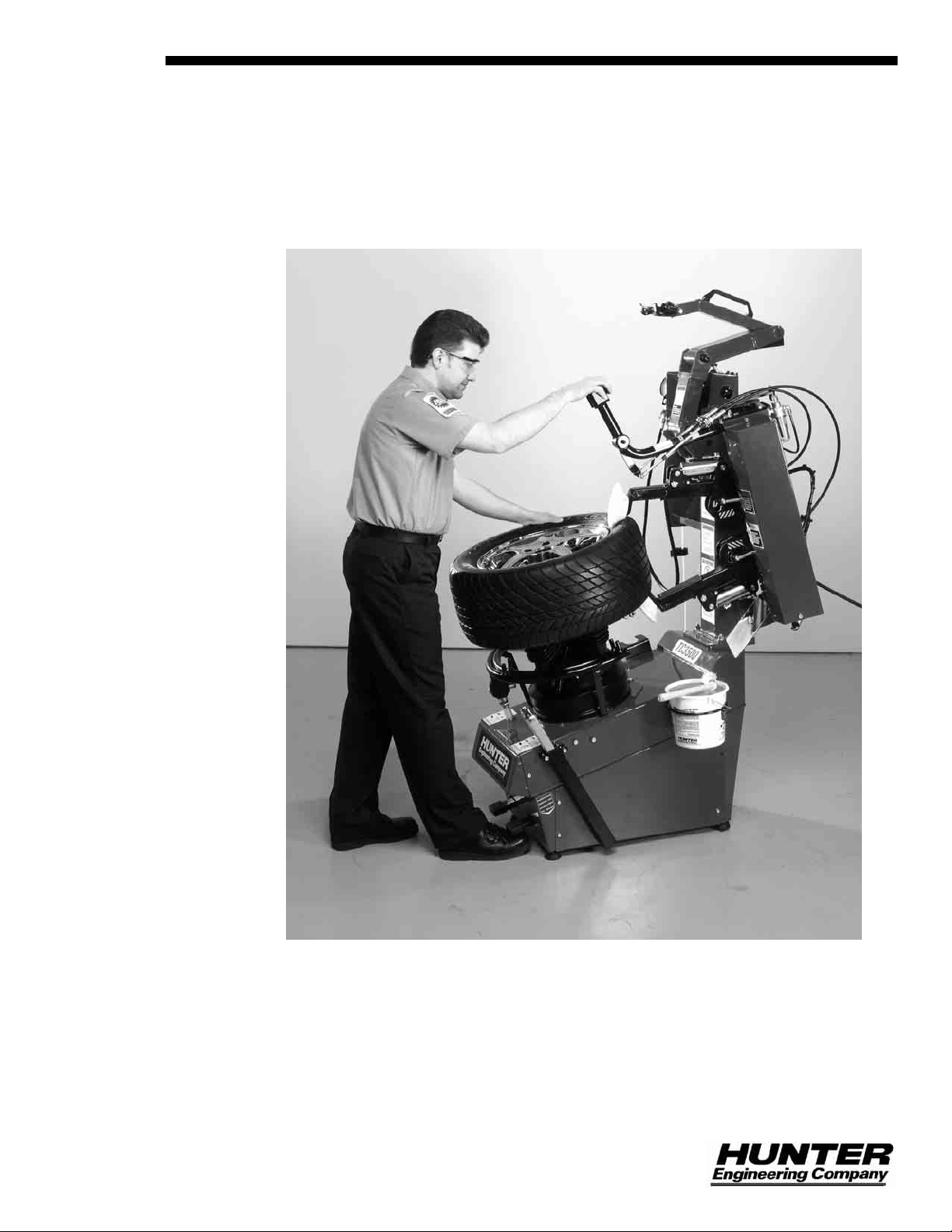
TC3500 Tire Changer
Form 4352T, 02-05
© Copyright 1998 - 2003 Hunter Engineering Company

OWNER INFORMATION
Model Number ____________________________________________________________________
Serial Number ____________________________________________________________________
Date Installed_____________________________________________________________________
Service and Parts Representative _____________________________________________________
Phone Number____________________________________________________________________
Sales Representative_______________________________________________________________
Phone Number____________________________________________________________________
Safety Precautions
Concept and Procedure Explanation
Trained Declined
Warning and Caution Labels
Bead Roller
Maintenance and Performance Checks
Trained Declined
Air Pressure and Volume Check
Checking Arm Calibration to Rims
Rollers Parallel to Rim/Reference Gauge
Checking Angle of Rollers to Center Support
Adjustment and Filling of Oilers
Oil Type/Lubrication Fittings
Mounting Head and Rubber Pad Inspection (on TC3500-SS models)
Internal Clamping
Trained Declined
Rubber Pad Positioning
Conical Rims/Use of Rim Securing Device
Steel Jaw Use
External Clamping
Trained Declined
Rubber Jaw Positioning
Clamp Without Center Support
Bead Loosening
Trained Declined
Standard Wheels
Low Profile Wheels
AH2 Wheels
Cylindrical Wheels
Drop Center Identification and Tire Lubrication
Side Shovel Operation (on TC3500-SS models)

Demounting Trained Declined
90°/110° Position of Arm to Rim
Standard Wheels with Bead Lever and Plastic Sleeve Protector
Low Profile Wheels with Bead Lever, No Plastic Sleeve Protector
Assistance of Bottom Roller
Installation and Removal of Bead Depressor Tail
Full Seating of Mount/Demount Head to Prevent Head Failure
Bead Lubrication during Removal of Low Profile Tires
Reverse Drop Center Wheels
“HM” Bead Lever Technique
Mounting
90°/110° Position of Arm to Rim
Standard Wheels
Low Profile Wheels with Use of Bead Depressor and Upper Roller
Mounting of Stiff, Low Profile Tires on Rounded Edged Rim
Reverse Drop Center Wheels
Proper Bead Lubrication for Mounting Protection
Installation and Removal of Bead Depressor Tail
Mounting Counterclockwise with Upper Roller and No Mounting Head
Matching Tire to Rim
Lubrication, Positioning, and Direction of Rotation
Inflation
Adjustment of Pre-Set Pressures
Lubrication and Removal of Valve Core
Individuals and Date Trained
__________________________________ __________________________________
__________________________________ __________________________________
Trained Declined
Trained Declined
Trained Declined
__________________________________ __________________________________
__________________________________ __________________________________
__________________________________ __________________________________
__________________________________ __________________________________
__________________________________ __________________________________


Contents
1. Getting Started...........................................................................................1
1.1 Introduction .............................................................................................................1
1.2 For Your Safety.......................................................................................................1
Hazard Definitions............................................................................................1
IMPORTANT SAFETY INSTRUCTIONS.........................................................2
1.3 Wheel Clamping Pedal ...........................................................................................3
1.4 Tire Bead Loosening / Wheel Rotation Pedal (TC3500-SS Models only)..............3
1.5 Wheel Rotation Pedal.............................................................................................3
1.6 Air Inflation Pedal....................................................................................................4
1.7 Inflator and Pressure Limiter...................................................................................4
1.8 Command Unit........................................................................................................4
1.9 Equipment Components .........................................................................................6
2. Basic Procedures.......................................................................................9
2.1 Bead Loosening (TC3500-SS Models only)...........................................................9
2.2 Placing Wheel on TC3500......................................................................................9
Clamping the Wheel from Inside of Rim........................................................10
Installation of Optional Wheel Securing Device......................................11
Installation of Steel Jaws.........................................................................12
Clamping the Wheel from Outside of Rim .....................................................12
Clamping Reverse Drop Center Wheels .......................................................13
2.3 Bead Loosening Standard Rim and Tire ..............................................................13
2.4 Demounting Standard Tires from Rim..................................................................14
2.5 Mounting Standard Tire to Rim.............................................................................16
Precautionary Notes ......................................................................................17
2.6 Tire Inflation ..........................................................................................................17
2.7 Removal of Wheel from Tire Changer..................................................................18
3. Advanced Procedures.............................................................................19
3.1 Advanced Bead Loosening Procedures...............................................................19
Bead Loosening Soft Sidewall, Tall Profile Tires...........................................19
Bead Loosening Tough, Low Profile Tires.....................................................20
Bead Loosening “AH” Wheels .......................................................................20
3.2 Advanced Demounting Procedures......................................................................22
Using “HM” Bead Lever and Sleeve Protector ..............................................22
Using Bead Depressor “Tail” and Bottom Roller to Demount Upper Bead without
Sleeve Protector ............................................................................................22
Using Force Multiplier, RP6-8832..................................................................25
Demounting Lower Bead without Sleeve Protector.......................................26
Cylindrical Rims/Bead Loosening and Demounting Lower Bead..................27
3.3 Advanced Mounting Procedures...........................................................................27
Mechanical Bead Pusher, RP6-2413 ............................................................28
Mounting of Stiff Sidewall, Low Profile Tires..................................................28
Removal of Bead Depressor “Tail” ................................................................30
Mounting Low Profile Tires on Rounded Edged Rims...................................31
3.4 Mounting Stiff, Low Profile Tires on Rounded Edged Rims Using Roller and No
Mounting Head............................................................................................................32
3.5 Mounting 20-Inch and Larger Automotive Wheels and Tires...............................33
3.6 Matching/Optimizing of Tire to Rim.......................................................................33
TC3500 Operation Instructions Contents • i

3.7 Run-Flat Tire Service............................................................................................34
Basic Run-Flat / EMT Information..................................................................34
Run-Flat “Zero Pressure” Tires and Rims .....................................................34
Tire Monitoring System (TMS).......................................................................35
Sensors ...................................................................................................36
TMS Band Type Sensor Installation........................................................36
Demounting Run-Flat with Valve Type Sensor..............................................39
Mounting Run-Flat with Valve Type Sensor ..................................................43
Inflating Run-Flats..........................................................................................48
Demounting Run-Flat with Band Type Sensor..............................................49
Mounting Run-Flat with Band Type Sensor...................................................55
3.8 Servicing BMW Z3 Motorsport Rear Reversed Drop Center 17x9AH2................59
Bead Loosening.............................................................................................60
Demounting....................................................................................................63
Mounting ........................................................................................................65
3.9 Optional Steel Mount/Demount Head Assembly (RP6-2654) ..............................68
4. Maintenance and Calibration..................................................................69
4.1 Maintenance Schedule .........................................................................................69
4.2 Maintenance Replacement Parts..........................................................................70
4.3 Calibrating and Adjusting the Position of the Column ..........................................70
4.4 Checking and Adjusting the Bead Rollers ............................................................71
4.5 Checking and Adjusting the Position of the Bead Breaker Arm...........................71
5. Glossary...................................................................................................73
5.1 Rim Diagram.........................................................................................................73
5.2 Illustration of AH2 Rim (Asymmetrical Humps) “Bead Locking System”.............74
5.3 Illustrations of Various Rim Designs.....................................................................75
ii • Contents TC3500 Operation Instructions

TC3500 Operation Instructions Contents • iii
1.1 Introduction
This manual provides operation instructions and information required to maintain the
TC3500 tire changer. An advanced operation section has been provided in
“Advanced Procedures.”
“References”
This manual assumes that you are already familiar with the basics of tire changing.
The first section provides the basic information to operate the TC3500. The following
sections contain detailed information about equipment, procedures, and
maintenance. “Italics” are used to refer to specific parts of this manual that provide
additional information or explanation. For example, Refer to “Equipment
Components,” page 6. These references should be read for additional information to
the instructions being presented.
The owner of the TC3500 is solely responsible for arranging technical training. The
TC3500 is to be operated only by a qualified trained technician. Maintaining record s
of personnel trained is solely the responsibility of the owner or management.
1. Getting Started
The TC3500 is intended for mounting, demounting, and inflating most tires with a
maximum dimension of 40 inches in diameter and 19 inches in width.
1.2 For Your Safety
Hazard Definitions
Watch for these symbols:
CAUTION: Hazards or unsafe practices, which could result in minor
WARNING: Hazards or unsafe practices, which could result in
DANGER: Immediate hazards, which will result in severe personal
These symbols identify situations that could be detrimental to your safety and/or
cause equipment damage.
personal injury, or product or property damage.
severe personal injury or death.
injury or death.
TC3500 Operation Instructions 1. Getting Started • 1
IMPORTANT SAFETY INSTRUCTIONS
NOTE: Operators of this equipment should review the Hunter
Training video before use. A certification test is also
available.
Read and follow all caution and warning labels affixed to equipment and tools.
Read and understand all instructions before operating this machine.
Misuse of this equipment can cause personal injury and shorten the life of the
TC3500.
To prevent accidents or damage to the TC3500, use only Hunter recommended
procedures and accessories.
Wear OSHA approved eye protection while operating the TC3500.
Wear non-slip safety footwear when operating the TC3500.
Do not wear jewelry or loose clothing when operating theTC3500.
Wear proper back support when lifting or removing wheel from the TC3500.
WARNING: Keep hands and clothing clear of moving parts.
Keep hands clear of upper roller when bead loosening
or rotating clamped wheel.
Do not lean or reach over tire when inflating.
Never stand on theTC3500.
WARNING: Do not exceed these pressure limitations:
SUPPLY LINE PRESSURE (from compressor) 220 PSI.
OPERATING PRESSURE (gauge on regulator) 145 PSI.
BEAD SEATING PRESSURE (gauge on hose) 40 PSI.
WARNING: Never mount a tire to a rim that is not the same diameter
(e.g., 16 1/2 inch tire mounting on a 16 inch rim).
DANGER: Activate air inflation ring only when seating bead.
Bleed air pressure from system before disconnecting supply line or other pneumatic
components. Air is stored in a reservoir for operation of the inflation ring. Air pressure
can be bled from the system by pulling up on the knob located on top of the
regulator, and then turning it counterclockwise.
Do not activate the air inflation ring if the tire is not properly clamped.
2 • 1. Getting Started TC3500 Operation Instructions
Do not operate TC3500 with worn rubber or plastic parts.
Wheels equipped with low tire pressure sensors or special tire and rim design may
require certain procedures. Consult manufacturer’s service manuals.
Service and maintain machine regularly as outlined in “Maintenance and Calibration,”
page 75. For further information contact:
Hunter Engineering Company
11250 Hunter Drive
Bridgeton, Missouri 63044
1-800-448-6848
Internet address: www.hunter.com
1.3 Wheel Clamping Pedal
The left pedal on the front of the base controls the wheel clamping. Refer to
illustration on pages 6 and 7.
Step down on the pedal to expand the wheel clamping device (arms move outward).
Lift the pedal to retract the wheel clamping device (arms move inward).
1.4 Tire Bead Loosening / Wheel Rotation Pedal (TC3500-SS
Models only)
WARNING: Keep arms and legs from between the bead breaker arm
and the side of the housing.
When the bead breaker arm is swung out away from the housing, the right pedal on
the front of the base engages to control the bead breaker arm. Refer to illustration on
page 7.
Step down on the pedal, to close the bead breaker arm, to loosen the bead.
Lift the pedal to allow the bead breaker arm to open.
The right pedal on the front of the base also controls the rotation of the wheel. Refer
to illustration on page 7.
Step down on the pedal to rotate the wheel clockwise (mounting and demounting).
Lift the pedal to rotate the wheel counterclockwise (bead loosening).
1.5 Wheel Rotation Pedal
The right pedal on the front of the base controls the rotation of the wheel. Refer to
illustration on page 6.
Step down on the pedal to rotate the wheel clockwise (mounting and demounting).
Lift the pedal to rotate the wheel counterclockwise (bead loosening and matching).
CAUTION: Keep hands clear of wheel, tire, and rollers during bead
loosening.
TC3500 Operation Instructions 1. Getting Started • 3

1.6 Air Inflation Pedal
The pedal on the left side of the base is a two-stage design. Refer to illustration on
page 6. The pedal controls the air going to the inflation hose and the dual air inflation
ring.
CAUTION: Keep hands clear of wheel during sealing and seating of
bead.
When operating air inflator, stand to the left side of the base. Do not stand in front of
the TC3500 while operating the air inflator.
Step down partially on the pedal to inflate tires through inflator hose.
Step down completely on the pedal to activate the air inflator ring to seal tire beads.
The TC3500 features a dual air inflation ring. When the diverter valve is pushed in,
air will be directed through the inner ring. When the diverter valve is pulled out, air will
be directed through the outer ring. Due to the wide variety of wheel and tire
combinations, determining which rings works best for any particular wheel and tire
combination will be by trial and error.
1.7 Inflator and Pressure Limiter
As a safety device, the pressure limiter prevents the operator from using excessive
air pressure to seat the tire bead during tire inflation. Bead seating pressure should
never exceed 40 psi. If tires being mounted require more than 40 psi for inflation
pressure, the tire/wheel assembly should be removed from the TC3500, placed in an
inflation cage, and inflated per manufacturer’s instructions.
While inflating the tire, the pressure gauge will read zero until the inflation pedal is
released. At that time, the gauge will give the correct air pressure reading in the tire.
1.8 Command Unit
The command unit governs all the movements necessary for complete bead roller
operation. Refer to illustration on page 6.
The command unit is used to position the bead roller into the working position.
For proper operation of the command unit, place your hand over controller with index
finger and middle finger over lever buttons.
Push and pull the command unit to bring the rollers to the correct rim diameter.
The rim diameter that the bead rollers are set to is indicated on the scale of the
handle support. The scale is only a reference. All rims differ in flange design.
The command unit has two pneumatic lever buttons:
Left button controls the upper bead roller arm assembly.
Right button controls the lower bead roller arm assembly.
Each button has three positions:
In first position, bead roller arms are retracted.
In second position, bead roller with air pressure lightly contacts the
sidewall of the tire. The bead roller stays in this position until the button is
depressed or retracted.
In third position, the bead roller applies hydraulic pressure to push the
bead of the tire inward.
4 • 1. Getting Started TC3500 Operation Instructions
TC3500 Operation Instructions 1. Getting Started • 5
1.9 Equipment Components
TC3500
6 • 1. Getting Started TC3500 Operation Instructions
TC3500-SS
TC3500 Operation Instructions 1. Getting Started • 7

8 • 1. Getting Started TC3500 Operation Instructions
2. Basic Procedures
2.1 Bead Loosening (TC3500-SS Models only)
For bead loosening with rollers, refer to “2.3 Bead Loosening Standard Rim and
Tire,” page 13.
Remove valve stem core and deflate tire completely.
WARNING: All air pressure inside the tire must be removed before
proceeding. Never attempt to loosen the bead until all
air is removed from the tire. Failure to remove all air
from tire may result in injury to operator, or damage to
equipment, tire, or wheel.
Remove all weights from the rim to protect the rim and to extend life of the
mount/demount head.
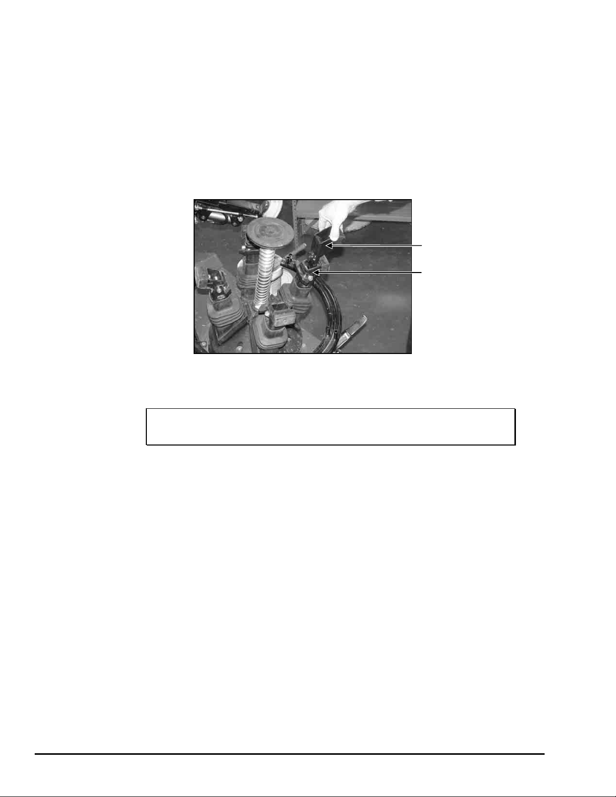
Swing the bead breaker arm out and away from the housing.
Position the wheel against the side of the TC3500-SS, between the bead breaker
arm and the housing.
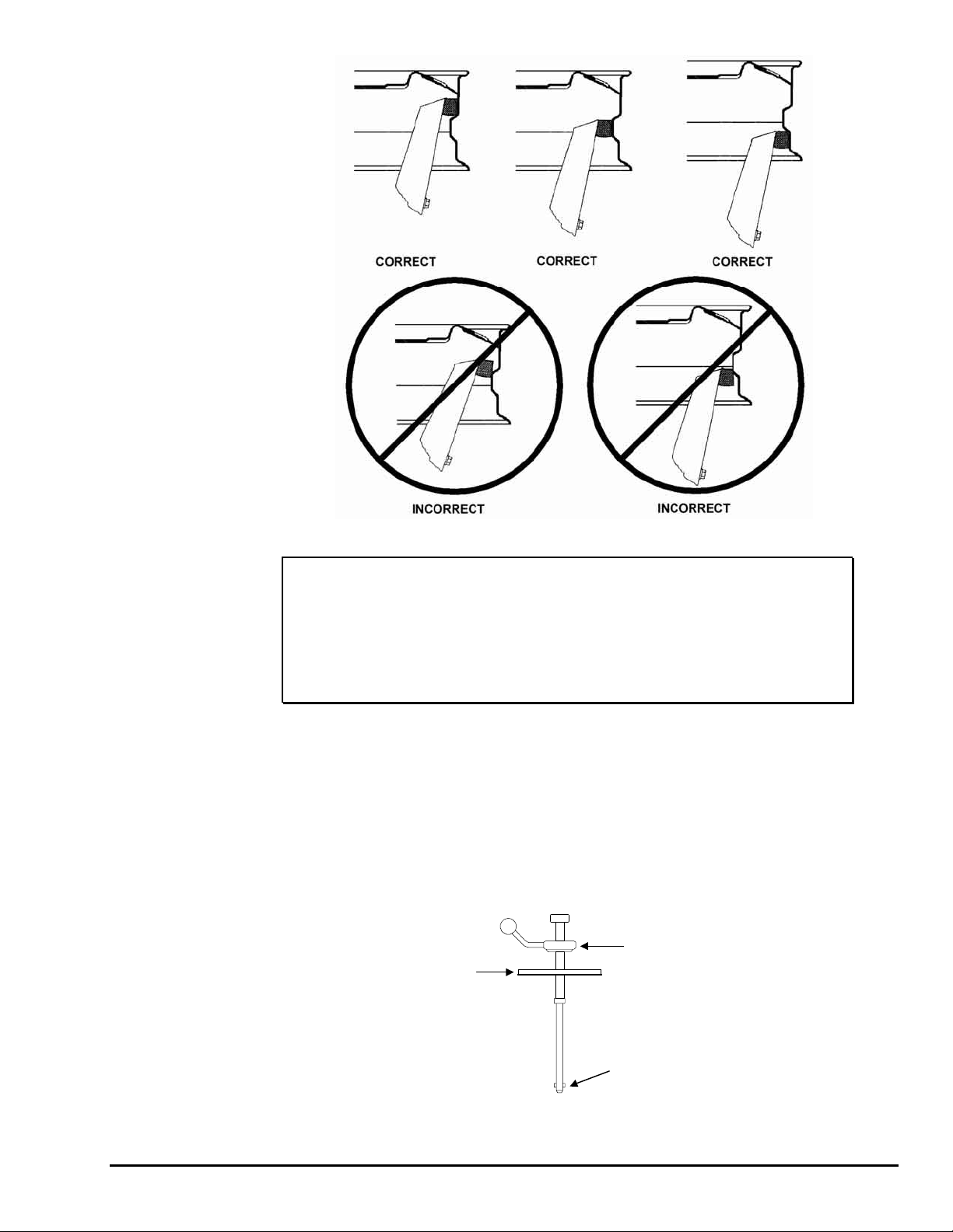
Swing the bead breaker arm toward the tire and position the blade two to three
inches from the edge of the rim on the sidewall of the tire.
Step down on the right pedal. The bead breaker arm will be pulled toward the
TC3500-SS to loosen the bead.
Lift and hold the right pedal up to disengage the bead breaker arm and then swing
the arm to the open position. Once the arm has been swung to the open position,
release the pedal.
If the bead has not completely loosened, rotate the wheel and repeat the bead
loosening procedure at a different area on the tire.
Turn the wheel and loosen the opposite bead using the same procedure.
2.2 Placing Wheel on TC3500
The “tulip arm clamping” design is truly exclusive in its versatility and ability to grip
wheels without damaging the surface finish.
Remove valve stem core and deflate tire completely (if not done previously).
WARNING: All air pressure inside the tire must be removed before
proceeding. Failure to remove all air from tire may result
in injury to operator or damage to equipment, tire, or
wheel.
TC3500 Operation Instructions 2. Basic Procedures • 9
Remove all weights from the rim to protect the rim and extend life of mount/demount
A
head (if not done previously).
Identify and recognize special wheel combinations such as Reverse Drop Center,
AH2, and “Run-Flat” Extended Mobility Tires (EMT).
Identify the inner locations on the rim where the rubber pads of the clamping arms
will come in contact in a parallel manner.
Clamping the Wheel from Inside of Rim
If servicing wheels larger than 20 inches in diameter, insert one adaptor, RP6-6494,
into each of the tulip arms.
DAPTOR,
RP6-6494
TULIP ARM
Verify that removable rubber coated jaws are not installed in clamping arms.
Lift the clamping (left) pedal to retract the clamping device.
NOTE: Periodically clean and degrease the rubber pads to remove
dirt and debris before placing the wheel on the TC3500.
Place the wheel onto the spring-loaded, wheel-centering device.
Push down on the wheel to locate the desired area to which the rubber pads will be
applied. Hold the wheel at this location until properly clamped.
Step down on the clamping pedal until the wheel is completely clamped by the
rubber pads.
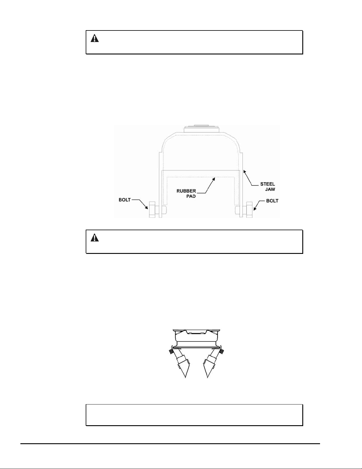
Verify that the entire face of the rubber pad contacts the rim. If the rubber pad is
partially pushed against a sharp corner or radius on a rim, the clamping force will
cause uneven pressure and eventually “chunk” the pads.
The amount of pressure being applied by the rubber pads to the rim can be
increased or decreased by depressing or lifting the clamping pedal. Apply only
enough pressure to keep the rim from rotating or coming loose during tire
demounting/mounting. Weak rims (e.g. wire wheels, etc.) can be lightly clamped by
applying minimal pressure.
10 • 2. Basic Procedures TC3500 Operation Instructions
Verify that the wheel has been properly clamped and centered.
NOTE: On conical shaped rims, always clamp the rim at a position
parallel to the feet to prevent slippage. If the rim clamping
area is oily or wet, clean the backside of the rim or install the
steel clamping jaws, RP6-2035, on the rubber pads to
increase rim gripping ability or use the wheel securing
device. Refer to “Installation of Wheel Securing Device,”
page 11 or to “Installation of Steel Jaws,” page 12.
Installation of Optional Wheel Securing Device
The wheel securing device, RP6-1485, may be used if clamping conical internal rim
shapes, wet or oily rims, run-flat or stiff sidewall tires. The primary purpose of this
device is to prevent the rim from popping up during clamping. It is not to be used to
hold the wheel during bead loosening procedures.
Position the wheel securing device through the center hole of the rim until it has been
inserted into the wheel centering support.
Insert the locking pin of wheel securing device into the center support nut by rotating
clockwise.
LOCKING RI NG
PLATE
LOCKING PIN
WHEEL SECURING DEVICE
Position plate and lock into place by rotating locking ring clockwise.
TC3500 Operation Instructions 2. Basic Procedures • 11
If lock pin will not engage, loosen clamping arms and reposition pin.
CAUTION: The wheel securing device is not to be used as a safety
related hold-down tool.
Installation of Steel Jaws
The steel clamping jaws, RP6-2035, may be used if the rim clamping area is oily or
wet. Install the jaws onto the rubber pads to increase rim gripping ability.
Place a steel jaw onto a rubber pad of a centering arm.
Push the steel jaw completely onto the rubber pad.
Hand-tighten the bolt located on each side of the steel jaw securing it to the centering
arm.
Repeat above steps to install remaining steel jaws.
CAUTION: Steel jaws may damage the finish of the inside rim surface
during use.
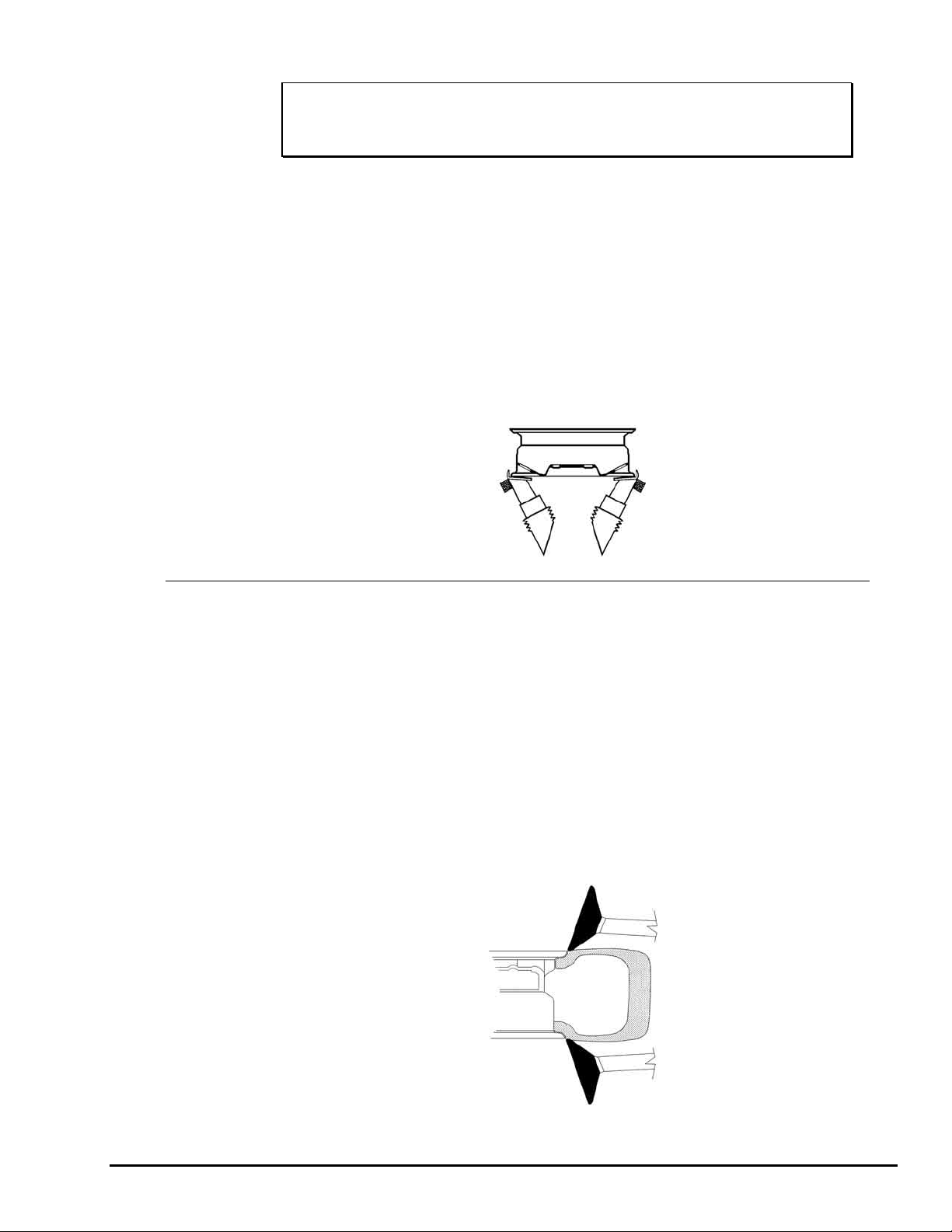
Clamping the Wheel from Outside of Rim
If servicing wheels larger than 22 inches in diameter, insert one adaptor, RP6-6494,
into each of the tulip arms.
Install removable rubber coated jaws into clamping arms by sliding the lower prongs
beneath the bolt that attaches the arm stop to the clamping arms.
Step down on the clamping pedal to expand the clamping device.
Rotate the arms to the 4 and 7 o’clock positions.
Place the wheel onto the two jaws at 4 and 7 o’clock positions.
Push down on the wheel to position the wheel onto two of the four jaws on the
clamping device.
Lift the clamping (left) pedal until the rim is completely clamped by the jaws.
NOTE: Always verify all four arms are clamping rim before applying
pressure to prevent possible failure.
Remove rubber coated jaws when finished with external clamping.
12 • 2. Basic Procedures TC3500 Operation Instructions
Clamping Reverse Drop Center Wheels
HINT: Identify reverse drop center wheels while you are loosening
the bead of the tire. This will help you properly identify the
proper procedure to use before demounting the tire.
Wheels with a reversed offset drop center must be mounted on the tire changer
upside down to remove the tire from the rim without damage.
Remove the wheel centering support before inverting wheel on clamps as follows:
Using a 36mm or 1 7/16 inch open end wrench, loosen the base of the wheel
centering support.
With bead lever, pry up on the center support spring to allow extra width to
insert open end wrench.
Rotate the wheel centering support counterclockwise until it is free from the
TC3500.
Lift the wheel centering support, removing it from the TC3500.
Store support in accessory brackets on left side of base.
Re-install wheel centering support after completing the tire changing procedure.
2.3 Bead Loosening Standard Rim and Tire
Swing in bead roller to locked position.
Adjust rim reference diameter.
Position upper roller at edge of rim by pressing the left button of the command unit to
the second position.
Position lower roller to edge of rim by pressing the right button of the command unit
to the second position.
Rotate wheel counterclockwise.
Apply hydraulic force to push both upper and lower beads simultaneously to begin
loosening beads.
Continue to rotate wheel during entire procedure.
TC3500 Operation Instructions 2. Basic Procedures • 13
CAUTION: Never rotate the wheel clockwise while bead loosening.
Never lock the bead roller assembly with the lock knob while
bead loosening.
Push the upper and lower bead of the tire off the rim bead seat.
CAUTION: Never place hands near the rollers while applying force and
rotating tire. Hands could be pulled between the roller and
tire causing injury.
Lubricate the lower bead and rim by inserting brush of lubricant into wheel just
behind the roller.
Lubricate the upper bead and rim as above.
Retract rollers.
Swing the bead roller assembly away to the stored position.
For additional information on special wheels, refer to “Advanced Bead Loosening
Procedures.”
2.4 Demounting Standard Tires from Rim
NOTE: For rims that have a clearcoat finish, clean the
mount/demount head to remove dirt and debris before
demounting the tire from the rim.
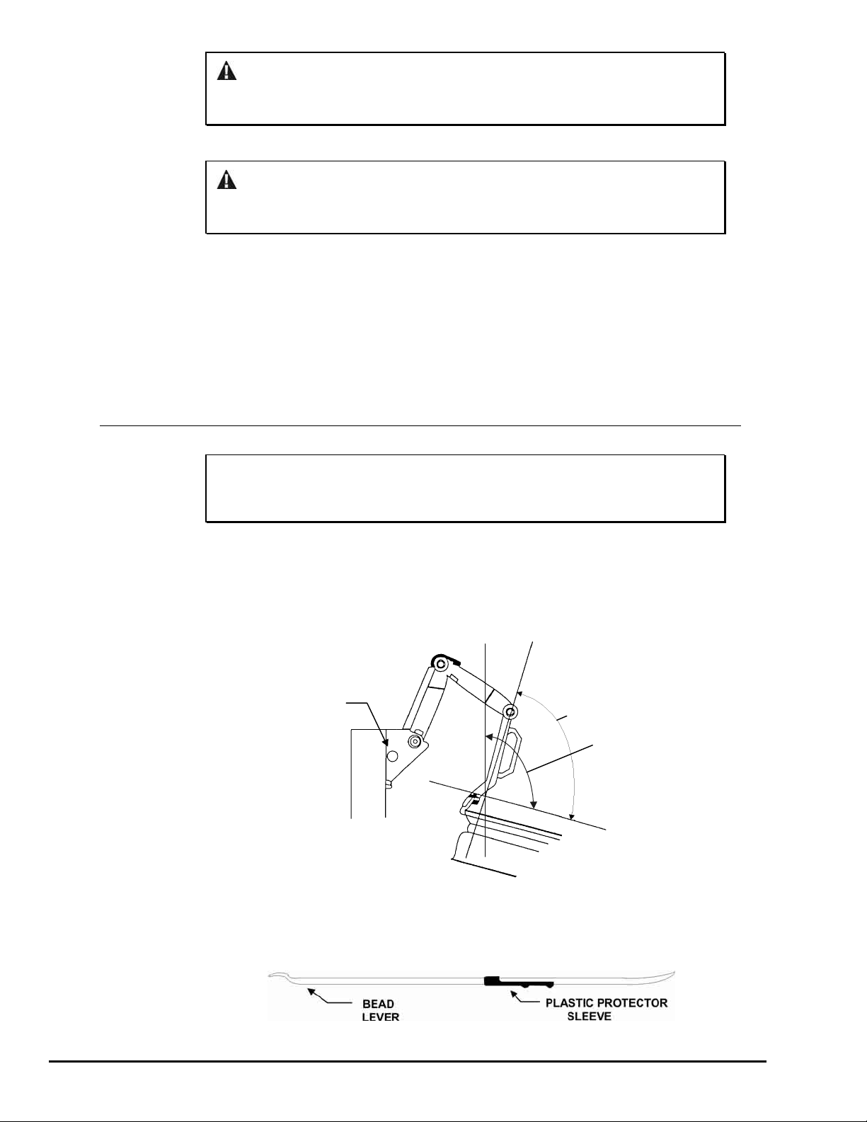
The angle between the tool arm and the rim flange must be close to 90 degrees.
The tool arm can be set to four different positions. The four positions are set by
pulling out the arm adjustment knob on the column and moving the arm manually
until it is locked in the required position. For rims with flat, rounded, or painted rim
lips, the angle between the mount/demount arm assembly arm and the rim flange
can be adjusted to approximately 110 degrees.
ARM
ADJUSTMENT
KNOB
90 DEGREES
110 DEGREES
Position and fully seat the mount/demount head onto the outer edge of the upper rim
lip.
Verify that the plastic protector sleeve is installed on the bead lever tool as shown
below.
14 • 2. Basic Procedures TC3500 Operation Instructions
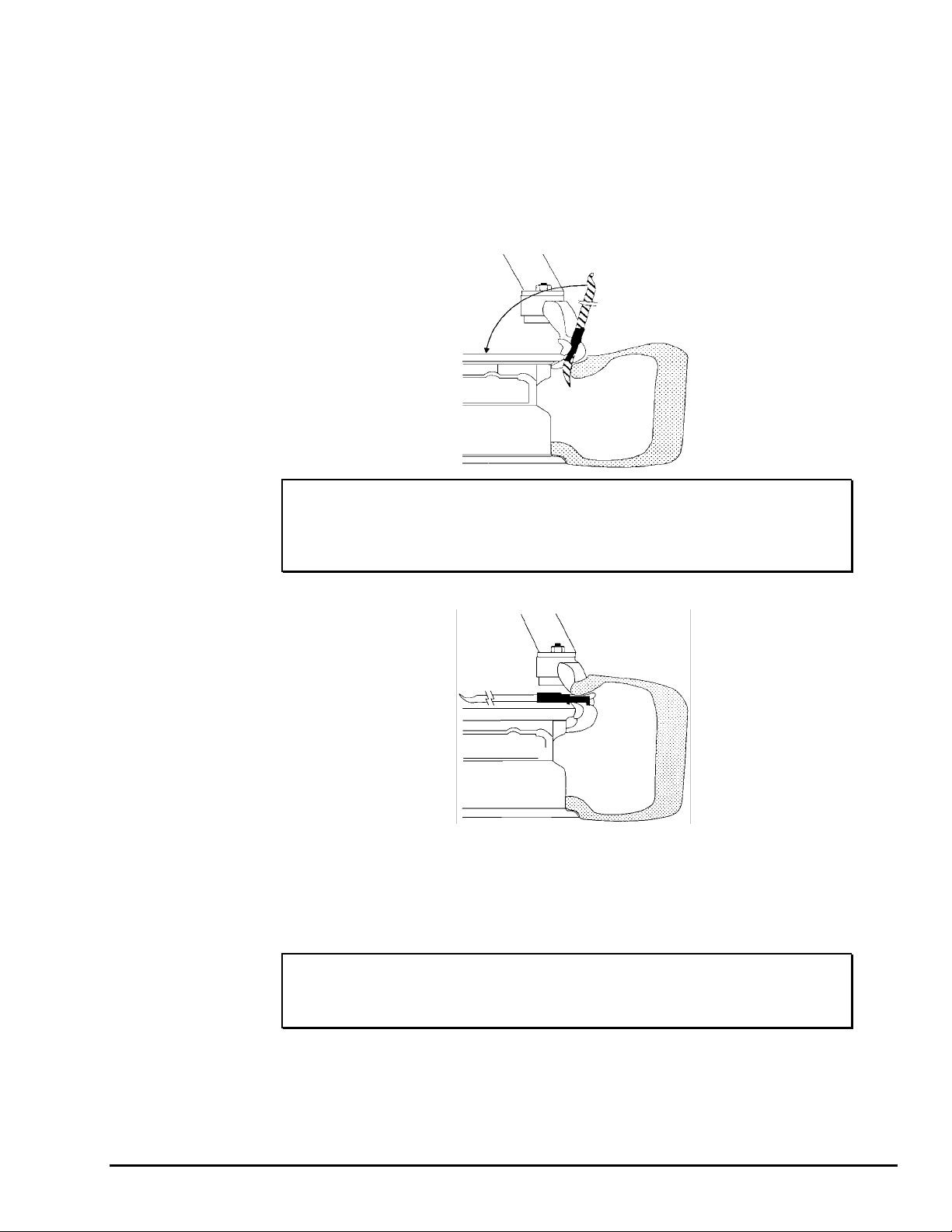
Position the straight end of the bead lever between right hand edge of
mount/demount head and bead of tire.
Slide plastic protector sleeve on the bead lever tool toward the tire.
The mount/demount head should be positioned between the humps of the plastic
protective sleeve.
Push down on the tire sidewall at the 6 o’clock position. On very stiff tires, use the
Bead Depressor “Tail” to slip the sidewall into the drop center of the rim. Refer to
“Using Bead Depressor “Tail” and Bottom Roller to Demount Upper Bead without
Sleeve Protector.”
IMPORTANT: To prevent the plastic protective sleeve and mount/demount
head from breaking during demounting, the mount/demount
head must be fully seated on the outer edge of the upper rim
lip before prying bead lever back for demounting.
Using the bead lever tool, lift the tire bead over the end of the head.
The bead lever tool must be pulled down parallel to the rim to prevent the possibility
of breaking the plastic sleeve protector.
Rotate wheel clockwise until the entire bead is lifted from the rim.
Lift tire and repeat this procedure for lower bead.
HINT: If lower bead becomes re-seated on rim, push lower bead
roller up against lower bead while rotating
counterclockwise to re-loosen.
Swing the mount/demount arm assembly up and away from the wheel.
Remove tire from rim.
For additional information on demounting special wheels, refer to “Advanced
Demounting Procedures.”
TC3500 Operation Instructions 2. Basic Procedures • 15
2.5 Mounting Standard Tire to Rim
Always be aware of this “checklist” when mounting tires to ensure proper service.
There are four basic steps when mounting a tire to a rim:
• Position the bead on top of the left lip of mount/demount head.
• Position the bead under the right lip of the mount/demount head.
• Lock the rim to the tire.
• Slip the bead into the drop center.
These four basic steps to mounting do not necessarily follow the same sequence,
however all four steps need to be performed to mount a tire to a rim.
Mount a standard tire to rim as follows:
Lubricate inside and outside of both beads of the tire to be mounted with
supplied mounting paste.
Position tire on top of the rim and tilt tire forward toward column.
Position mount/demount head through the opening of the tire and on the outer
edge of the rim lip.
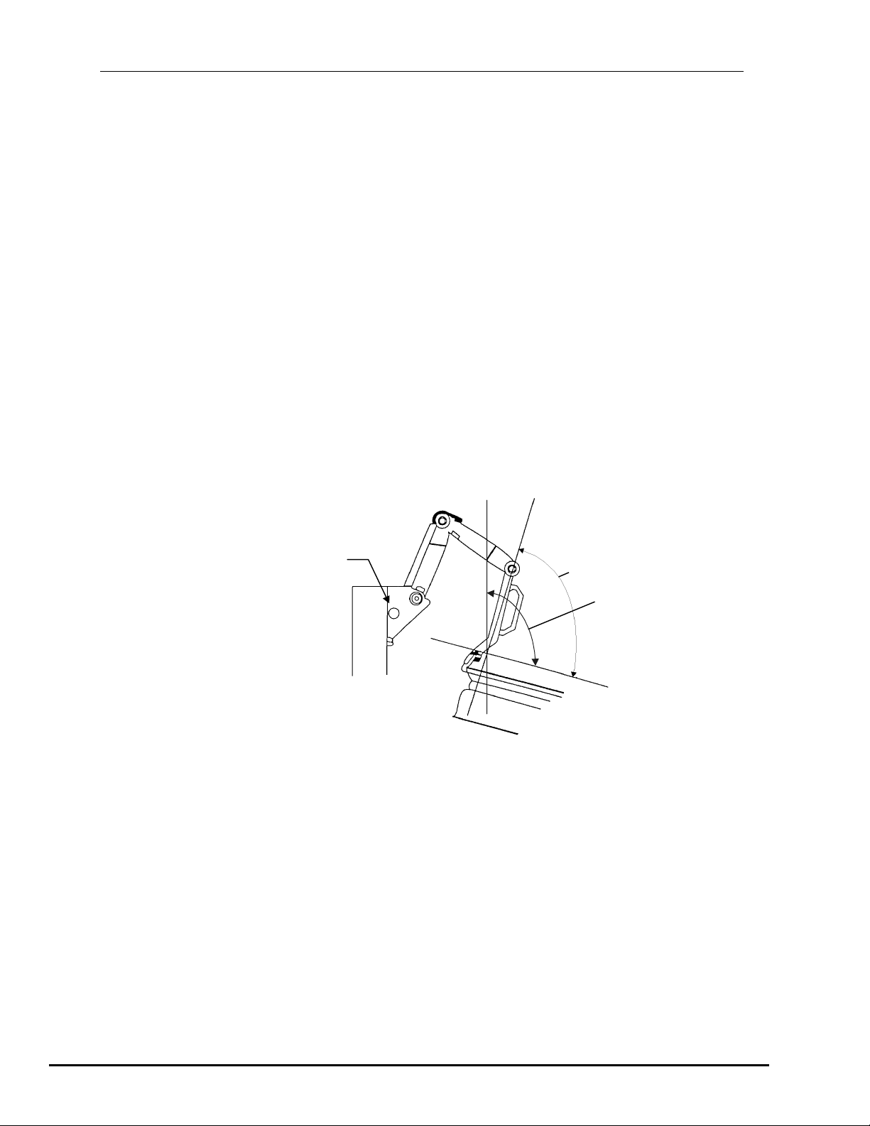
The angle between the tool arm and the rim flange must be close to 90
degrees.
ARM
ADJUSTMENT
KNOB
90 DEGREES
110 DEGREES
The mount/demount assembly arm can be set to four different positions. The
four positions are set using the arm adjustment knob on the column and
moving the arm manually until it is locked in the required position. For rims
with flat, rounded, or painted rim lips, the angle between the tool arm and the
rim flange can be adjusted to approximately 110 degrees.
Position edge of lower tire bead on top of the left lip of mount/demount head.
Push edge of lower tire bead under the right lip of the mount/demount head
while keeping other edge of lower tire bead above the left lip.
Twist tire clockwise by hand to lock the mounting of the tire to the rim.
Push down on tire at approximately the 6 o’clock position to slip the tire into
drop center.
Rotate wheel clockwise until the lower tire bead drops over the lip of the rim.
Repeat procedure on upper bead of tire, making sure to slip the bead
completely into the drop center of the rim, during mounting of the upper bead.
16 • 2. Basic Procedures TC3500 Operation Instructions
NOTE: If the tire bead does not have sufficient lubrication and the
For additional information on special wheels, refer to “Advanced Mounting
Procedures.”
Precautionary Notes
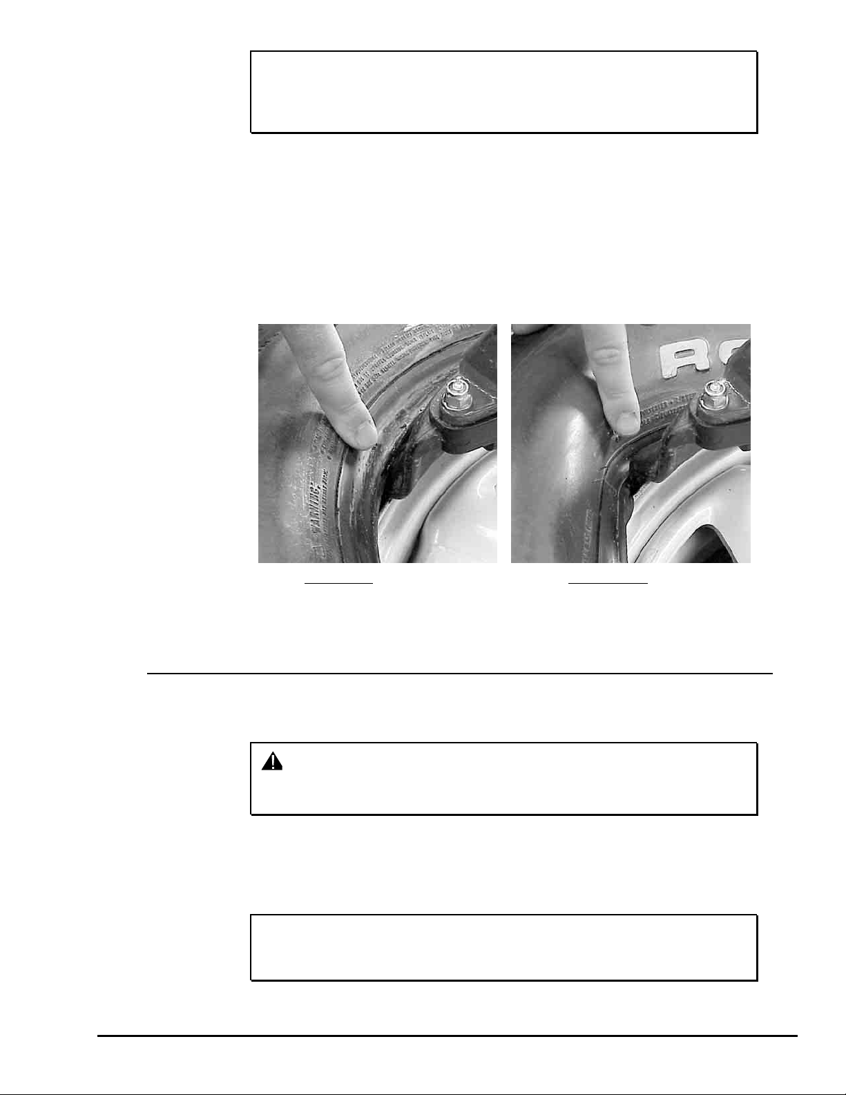
When basic procedures are not followed, sharp angled wheel flanges increase
potential damage to tires during mounting. Be sure the tire bead is placed on top of
the mounting head. If the tire is incorrectly pushed onto the rim by the side of the
mounting head, it may become “trapped” and increase mounting stress to the tire
bead.
tire fails to slip into drop center during mounting, the
mount/demount head may fail before damage to tire bead
takes place.
BEAD CORRECTLY PLACED ON TOP OF
Insufficient lubrication and failure to place tire into drop center during mounting may
also cause the mount/demount head to fail prematurely.
2.6 Tire Inflation
Verify that the wheel has been properly clamped and centered.
WARNING: Never attempt to inflate a tire when the wheel is clamped
Remove the valve stem core from valve stem. Removing the valve stem core will
allow the tire to inflate faster and the bead to seat easier.
Connect inflator hose to valve stem.
NOTE: To increase the effectiveness of inflation ring, always
MOUNTING HEAD
from the outside. Always reclamp the wheel from the
inside before inflating.
liberally lubricate the outer edge of the tire sidewall and pull
up on the tire while twisting to seal the bead.
TIRE IS INCORRECTLY PUSHED ON BY
MOUNTING HEAD
TC3500 Operation Instructions 2. Basic Procedures • 17

Step down completely on the air inflation pedal to release a high-pressure air blast
through nozzles on the air inflation ring to assist in seating the beads of the tire.
Step down partially on the air inflation pedal to inflate tire and seat the beads.
WARNING: Do not exceed 40 PSI when seating the beads of a tire.
After beads have been seated, disconnect inflation hose and reinstall valve stem
core previously removed. Then connect inflation hose and inflate tire to the required
pressure.
If the preset adjustable inflator is used, step down partially on the pedal until inflator
cycling stops. The tire will be inflated to the preset inflation pressure. Refer to “Inflator
and Pressure Limiter.”
If tire is over inflated, air may be removed from the tire by pressing the brass manual
air release button located below the air pressure gauge.
Disconnect inflator hose from valve stem.
2.7 Removal of Wheel from Tire Changer
Remove wheel-securing device, if installed.
For rims clamped on inside, lift the clamping pedal to release the rim from the
clamping device.
For rims clamped on outside, step down on the clamping pedal to release the rim
from the clamping device.
18 • 2. Basic Procedures TC3500 Operation Instructions
 Loading...