

Hunter 80210 Owner's Manual
Installation Guide
ENGLISH
See page 2
Consulter la page 23
FRANÇAIS
Vea la página 45
ESPAÑOL
Model 80210 Bath Ventilator with Light
43033-01 01/24/2008
READ and SAVE THESE INSTRUCTIONS
WARNING
!
TO REDUCE THE RISK OF FIRE, ELECTRIC SHOCK, OR INJURY TO PERSONS,
OBSERVE THE FOLLOWING:
1. Use this unit only in a manner intended by the manufacturer. If
you have questions, contact the manufacturer.
2. Before servicing or cleaning the unit, switch power off at service panel and lock the service disconnecting means to prevent
power from being switched on accidentally. when the service
disconnecting means cannot be locked, securely fasten a prominent warning device, such as a tag, to the service panel.
3. Installation work and electrical wiring must be done by qualified
person(s) in accordance with all applicable codes and standards,
including fire-rated construction.
Engineers (ASHRAE), and the local code authorities.
5. When cutting or drilling into wall(s) or ceiling, do not
damage electrical wiring or other hidden utilities.
6. Ducted fans must always be vented to the outdoors.
7. If this unit is to be installed over a tub or shower, it must be marked as
appropriate for the application and be connected to a GFCI (Ground
Fault Circuit Interrupter) - protected branch circuit.
8. Never place a switch where it can be reached from a tub or shower.
4. Sufficient air is needed for proper combustion and exhausting
of gasses through the flue (chimney) of fuel burning equipment
to prevent backdrafting. Follow the heating equipment manufacturer’s guideline and safety standards, such as those published
by the National Fire Prevention Association (NFPA), and the
American Society for Heating, Refrigeration and Air-Conditioning
!
1. For general ventilating use only. Do not use to exhaust hazardous or explosive materials and vapors.
2. To avoid motor bearing damage and noisy/unbalanced impellers, keep drywall spray, construction dust, etc. off power
unit.
3. DO NOT install this product in a wall. This product is
designed for installation in ceilings up to a 12/12 pitch (45
degrees). Ductwork must point upward.
4. Please read specification label on product for further information and requirements.
CAUTION
9. Install fan at least 5 feet (1.52 m) above the floor.
10. This unit must be grounded.
11. Unit must not be installed in a ceiling thermally insulated to a value
greater than R40.
DISCONNECT ELECTRIC
SERVICE PANEL BEFORE
PREVENTATIVE MAINTENANCE
A clean fan provides better service. Disconnect the power supply and clean the
fan as listed below.
TO CLEAN GRILLE: Use a mild detergent, such as dishwashing liquid, and a
soft cloth. DO NOT use abrasive cloths, steel wool pads or scouring powders.
TO CLEAN FAN ASSEMBLY: Unplug motor cord from receptacle. To remove
motor plate, find the single tab on the motor plate (located next to the recepta-
cle). Push up rear motor plate tab while pushing out on the side of the housing
or insert a screwdriver into the slot in the housing (next to tab) and twist screwdriver. Gently vacuum fan, motor and interior of housing.
METAL AND ELECTRICAL PARTS SHOULD NEVER BE IMMERSED IN
WATER.
WARNING
!
POWER SUPPLY
AND LOCK OUT
SERVICING UNIT
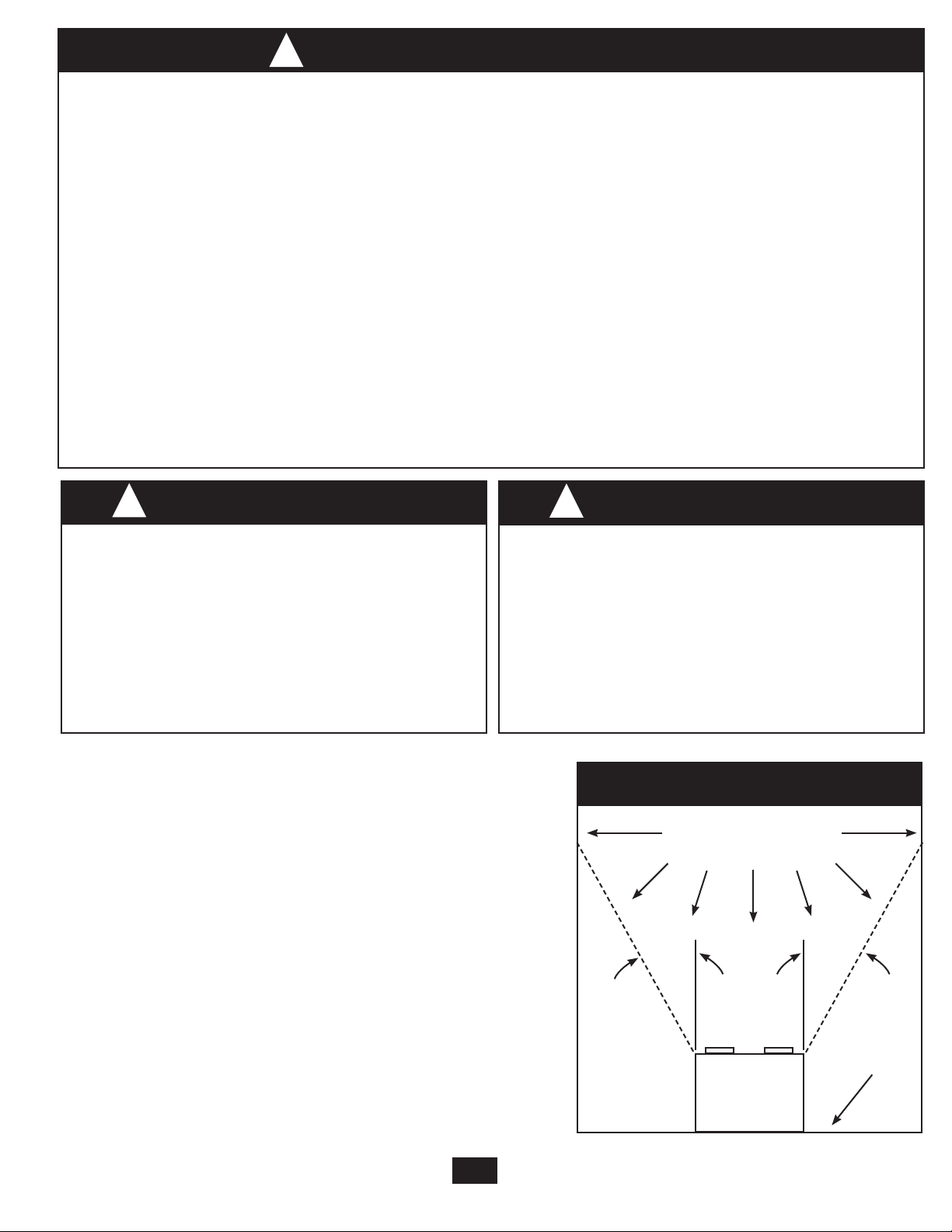
COOKING AREA
Do Not Install Above
Or Inside This Area
45° 45°
MAINTENANCE
The motor is permanently lubricated and never needs oiling. If the motor bearings are making excessive or unusual
noises, replace the motor with the exact service motor. You should replace the
impeller at the same time.
2
43033-01 01/24/2008
Cooking
Floor
Equipment
x2
D
E
F
G
H
I
L
M
N
95044-01-000
95029-01-000
75191-01-000
03242-07-133
98037-01
74508-03-133
98025-01
75184-01-133
Q
x4
*
*
*
NOTE:
Strain relief cable connector
must be installed. Not
Included.
A
B
C
Extra Screws
x2
I
3/8” Cable Connector
O
P
J
K
65219
66002-01
77539-01
98255-01
98044-01
77521-01
1
2
E
I
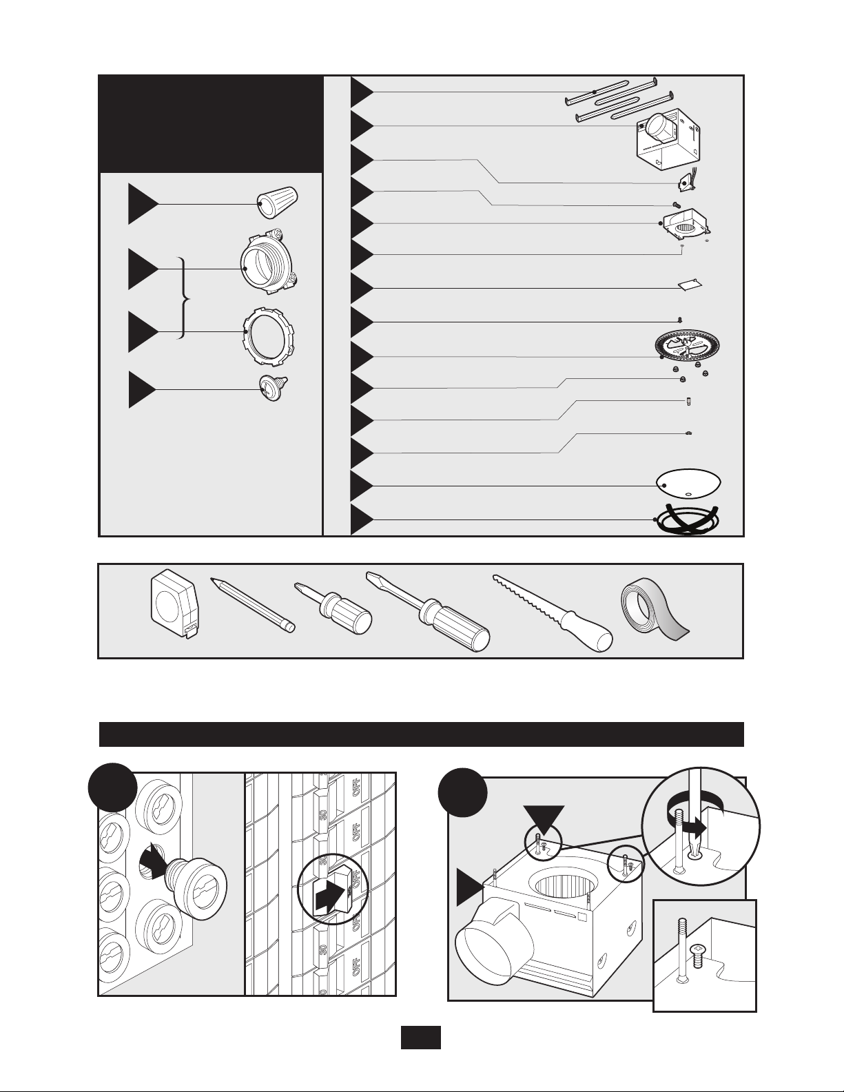
Check all the parts.
If damaged, call
1-888-830-1326
for replacements.
Before Installation
NOTE: Remove all packing materials before installation.
Estimated assembly time: 30 to 60 minutes
Included.
Tools Needed.
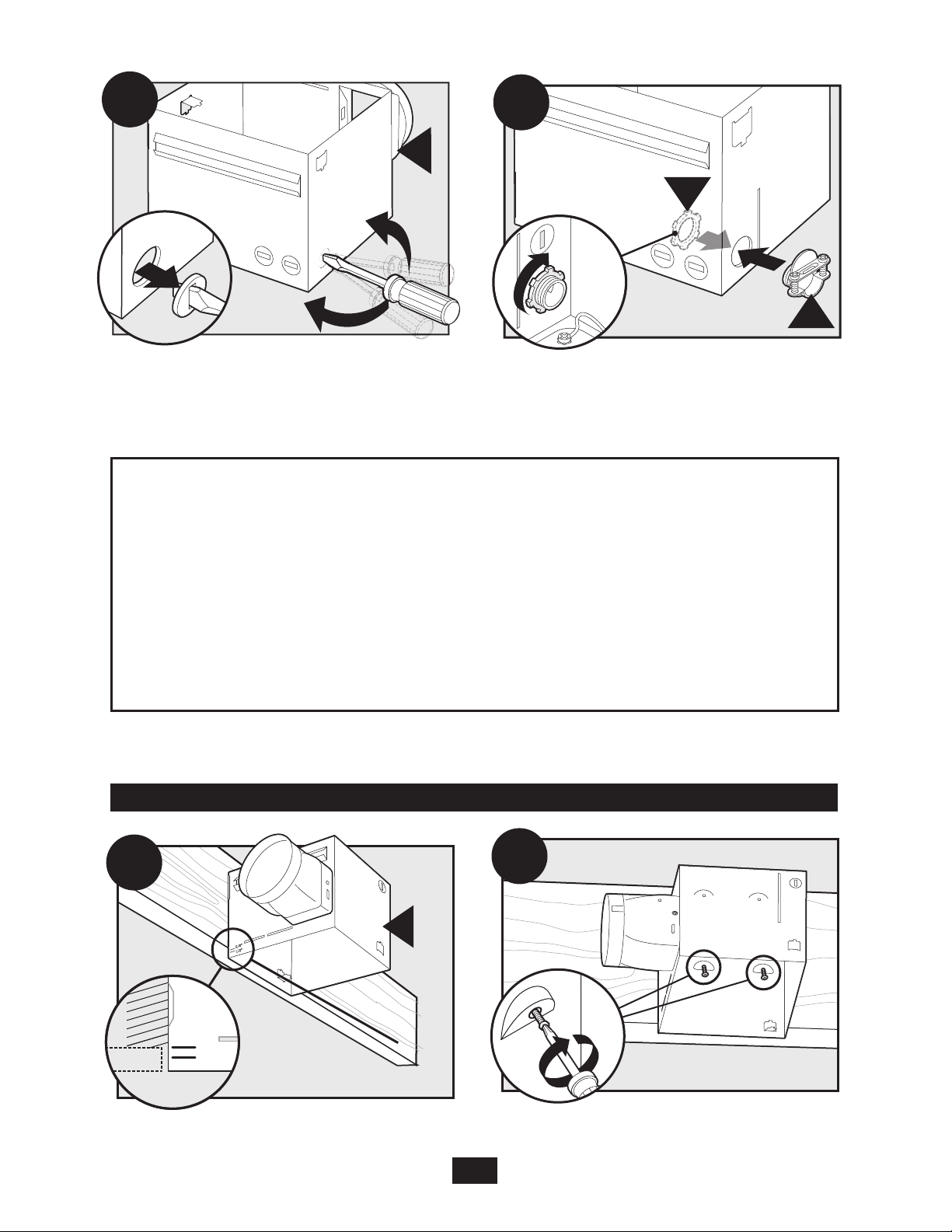
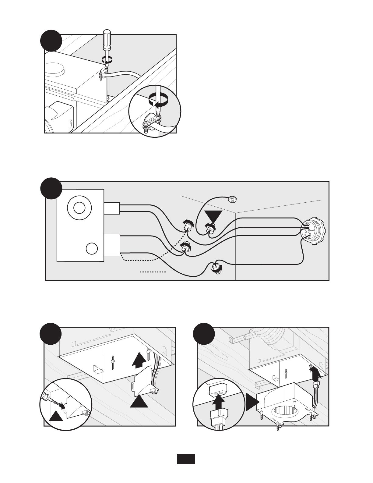
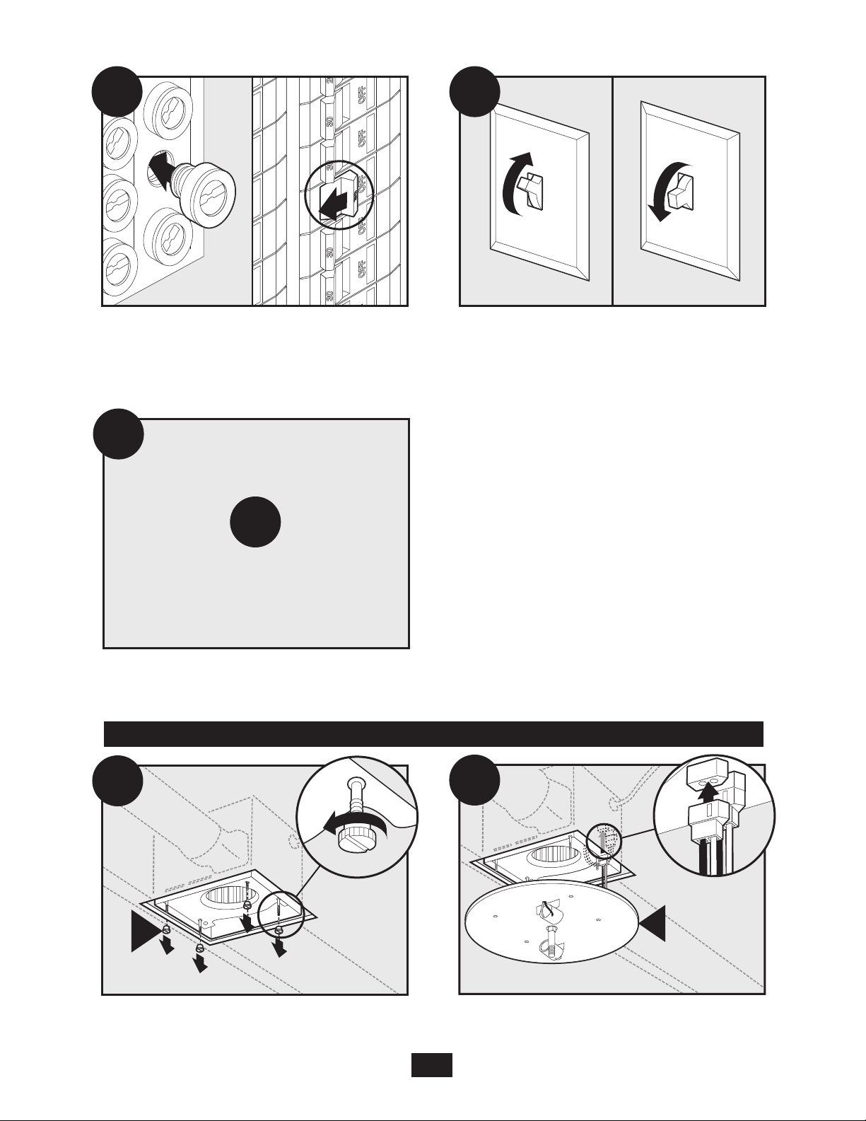
Turn off the power source.
Loosen screws.
3
43033-01 01/24/2008
5
4
7
G
8
F
H
E
3
6
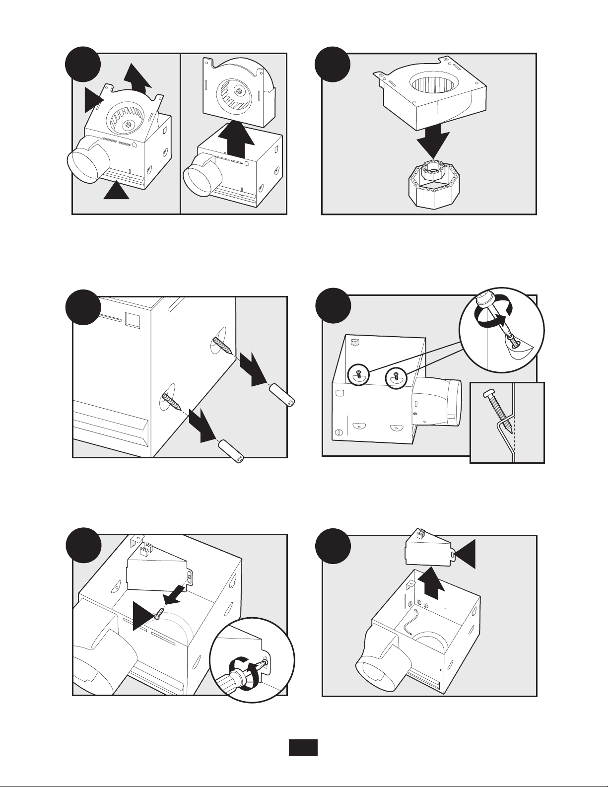
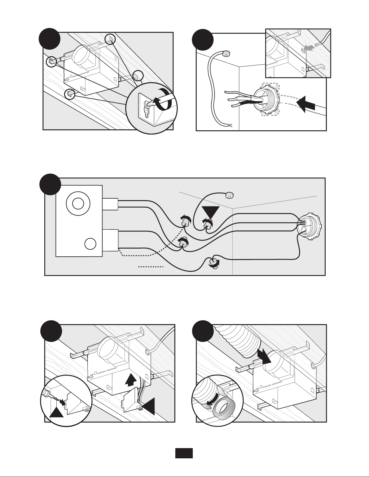
Remove the motor/blower from the housing.
Remove packing material.
Remove the pre-loaded screw tip covers.
Remove the wiring cover screw.
43033-01 01/24/2008
4
Back out the pre-loaded screw tips until flush
with the side of the housing.
Remove the wiring cover.
9
E
10
B
C
E
A11
5/8
1/2
A12
Pop out the first wiring access slug. Use second if
needed.
Insert the strain relief into the housing and
secure with the washer.
Choose Installation Option
For New Construction - attaching to joist go to step A11, page 5
For New Construction - suspended between joists go to step B11, page 8
For Existing Construction - accessible from above go to step C11, page 11
For Existing Construction - accessible only from below go to step D11,
page15
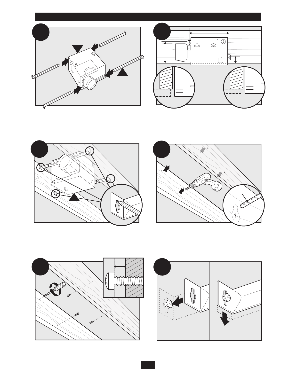
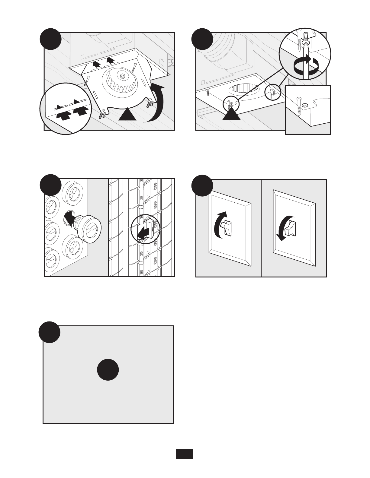
New Construction – attaching to joist
Position the correct depth mark at the bottom edge of
the joist based on the thickness of your sheetrock.
43033-01 01/24/2008
Screw pre-loaded screws into joist or framing.
5
A
3 Pin
2 Pin
Fan Motor
Light
Light
Green
Black
Black
White
Black
Black
White
White
Bare Copper
Ground
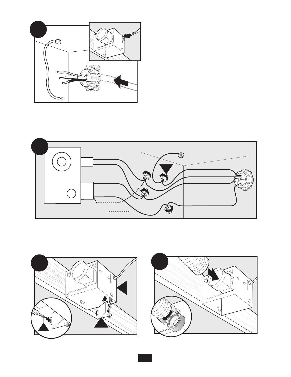
A14
Main Switch 1 (AC In)
Switch 2 (AC In)
*Option Fan & Main Light Together
*Option
A13
A16
A15
E
F
G
Pull wires through the strain relief.
Connect wires as shown.
Install the wiring cover plate. Make sure all
wiring connections are inside the box or under
the wiring cover plate.
Connect 4” duct and vent to the outside. Tape joints.
If ducting does not fit securely, an adapter may need
6
43033-01 01/24/2008
to be purchased.
A19
I
A20
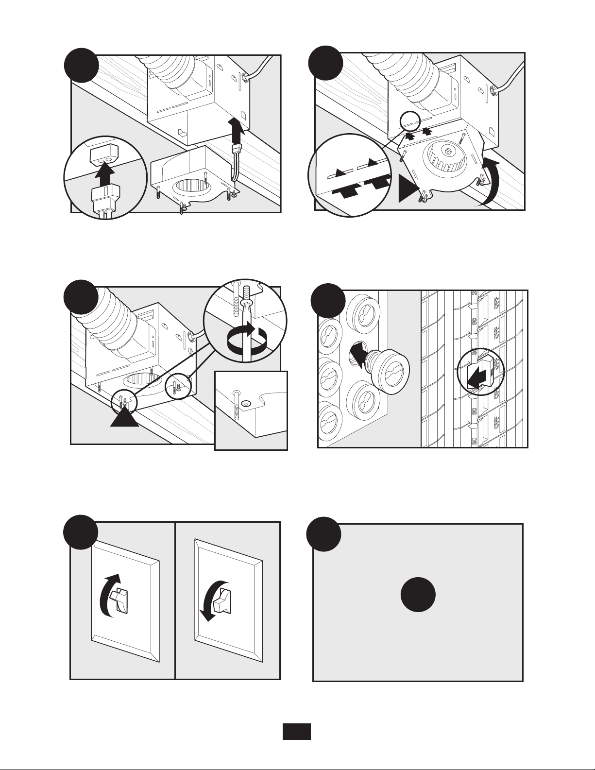
Connect wiring from the motor to the wiring cover
0000
A17
0000
H
A18
ON
OFF
A21
A22
E1
Go to step
on page 17
to attach grille.
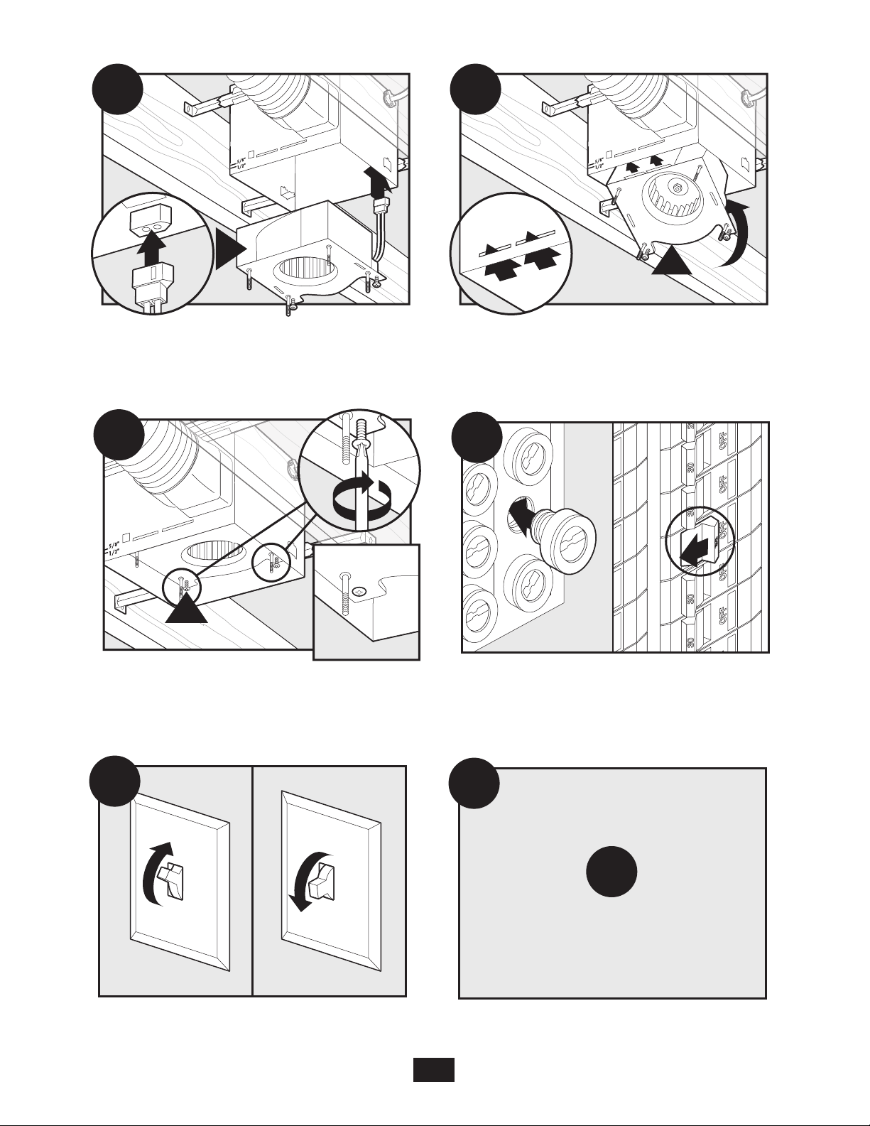
plate.
Reinstall the motor by inserting the tabs and pushing
up into position. Make sure the wires are not pinched
between the motor and the housing.
Secure the motor by tightening the 2 screws.
Test the motor. If the motor does not run, check the
Turn on the power source.
plug connection.
7
43033-01 01/24/2008
B11
D
E
5/8
1/2
5/8
1/2
B12
1/8" Bit
B14
B15
B16
E
B13
New Construction – suspended between joists
Slide the mounting rails into brackets.
Mark position of screws by using holes as a template.
Position the correct depth mark at the bottom edge of
the joist based on the thickness of your sheetrock.
Drill a hole in the center of each outline.
Insert screws, leaving space between the screw
head and the joist. Screws are not provided.
Attach the rails onto the screws.
8
43033-01 01/24/2008
B17
B18
A
3 Pin
2 Pin
Fan Motor
Light
Light
Green
Black
Black
White
Black
Black
White
White
Bare Copper
Ground
B19
Main Switch 1 (AC In)
Switch 2 (AC In)
*Option Fan & Main Light Together
*Option
B2 1
F
G
B20
Tighten screws. Pull wires through the strain relief.
Connect wires as shown.
Install the wiring cover plate. Make sure all wiring
connections are inside the box or under the
wiring cover plate.
Connect 4” duct and vent to the outside. Tape joints.
If ducting does not fit securely, an adapter may need
43033-01 01/24/2008
9
to be purchased.
B27
E1
Go to step
on page 17
to attach grille.
B22
H
Connect wiring from the motor to the wiring cover
H
B23
B25
ON
OFF
B26
B24
I
plate.
Reinstall the motor by inserting the tabs and pushing
up into position. Make sure the wires are not pinched
between the motor and the housing.
Secure the motor by tightening the 2 screws.
Test the motor. If the motor does not run,
check the plug connection.
Turn on the power source.
10
43033-01 01/24/2008
C12
D
E
EXISTING FAN
C11
NO EXISTING FAN
8”
8.5”
5/8
1/2
5/8
1/2
C13
C14
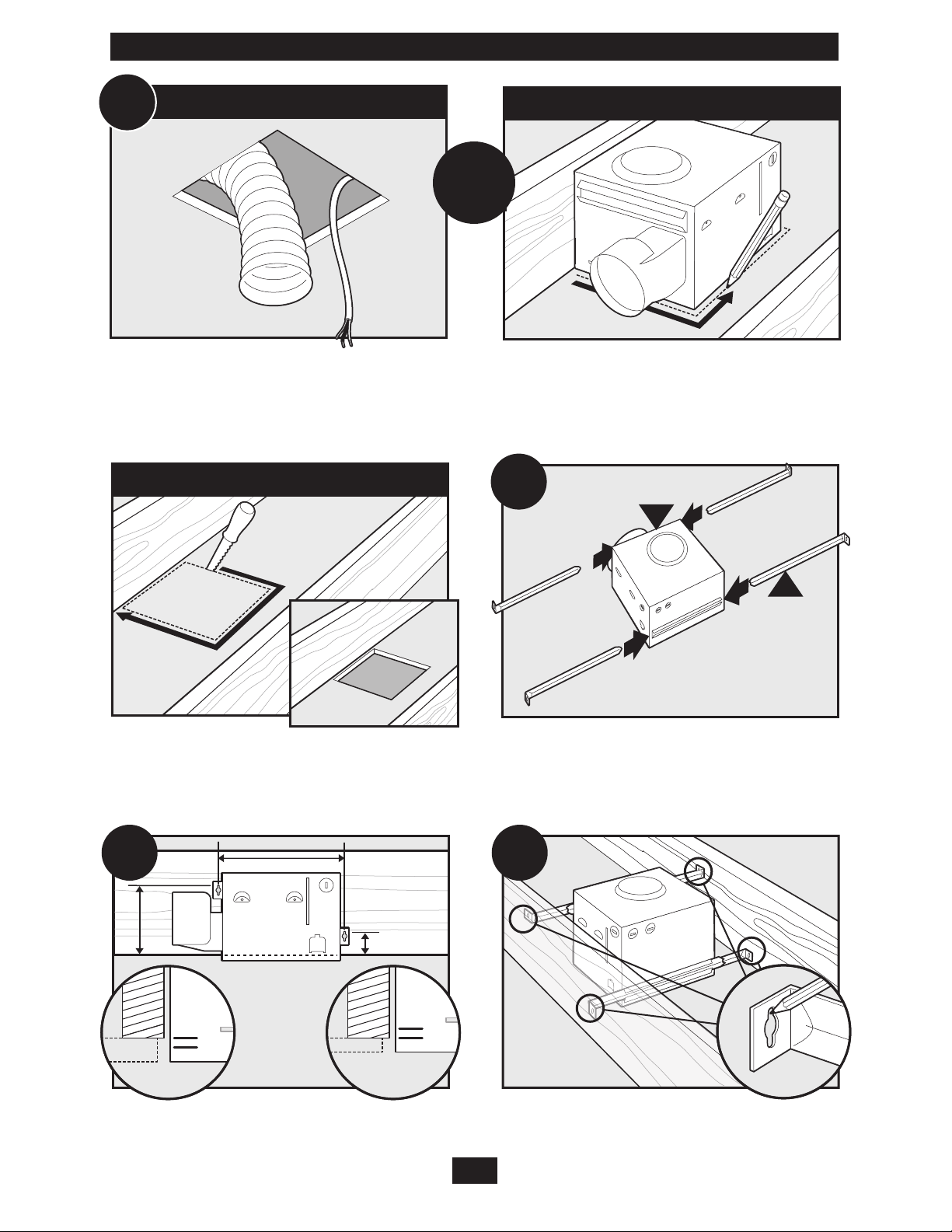
Existing Construction – accessible from above
OR
Remove an existing fan and check to make sure the
opening is large enough to accommodate the new
motor housing (8”x 8.5”).
Cut out an opening for the housing.
Use the motor housing as a template to mark position.
Slide the mounting rails into brackets.
Position the correct depth mark at the bottom edge of
the joist based on the thickness of your sheetrock.
Mark position of screws by using holes as a template.
11
43033-01 01/24/2008
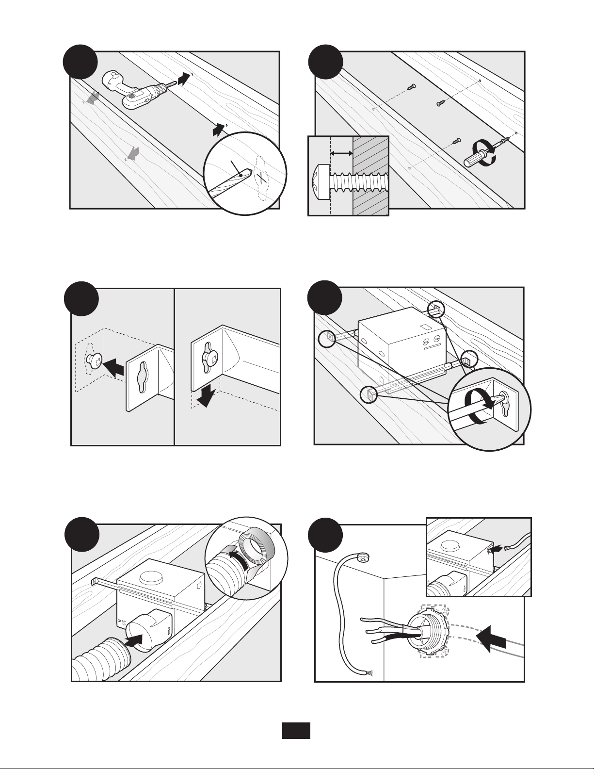
C15
1/8" Bit
C16
C17
C18
C19
C20
Drill a hole in the center of each outline. Insert screws, leaving space between the screw head
and the joist. Screws are not provided.
Attach the rails onto the screws. Tighten screws.
Connect 4” duct and vent to the outside. Tape joints.
If ducting does not fit securely, an adapter may
need to be purchased.
43033-01 01/24/2008
Pull wires through the strain relief.
12
C21
A
3 Pin
2 Pin
Fan Motor
Light
Light
Green
Black
Black
White
Black
Black
White
White
Bare Copper
Ground
C22
Main Switch 1 (AC In)
Switch 2 (AC In)
*Option Fan & Main Light Together
*Option
C24
H
G
F
C23
Tighten the strain relief screws.
Connect wires as shown.
Install the wiring cover plate. Make sure all wiring
connections are inside the box or under the
wiring cover plate.
13
43033-01 01/24/2008
Connect wiring from motor the motor
to the wiring cover plate.
C25
H
C26
I
C2 7
ON
OFF
C28
C29
E1
Go to step
on page 17
to attach grille.
Reinstall the motor by inserting the tabs and pushing
up into position. Make sure the wires are not pinched
between the motor and the housing.
Turn on the power source. Test the motor. If the motor does not run,
Secure the motor by tightening the 2 screws.
check the plug connection.
14
43033-01 01/24/2008
EXISTING FAN
D11
E
D12
D13
2
1
D14
E
D15
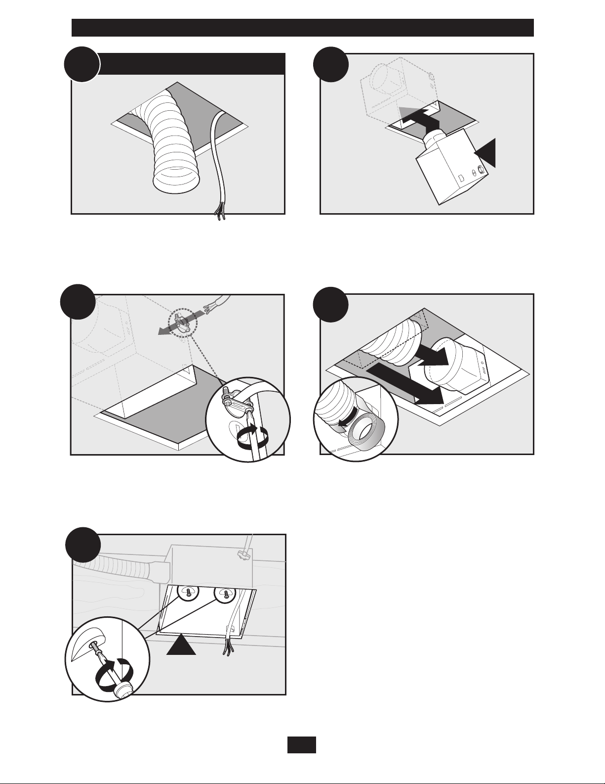
Existing Construction – accessible only from below
Remove an existing fan and check to make sure the
opening is large enough to accommodate the new
motor housing (8”x 8.5”).
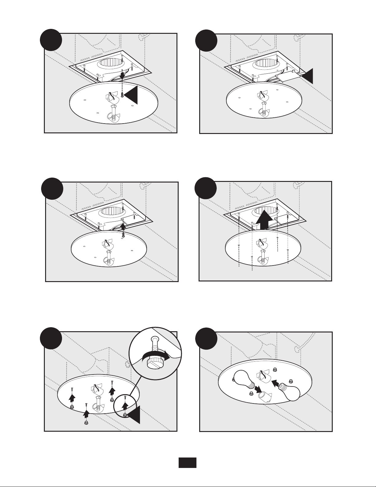
Pull wires through strain relief.
Move the housing into position above the ceiling.
Attach existing ducting to duct connector. Tape joints.
If ducting does not fit securely,
an adapter may need to be purchased.
Install the housing flush with the sheetrock and secure
by tightening the pre-loaded screws into the joist.
43033-01 01/24/2008
15
H
D18
H
D19
D20
I
A
3 Pin
2 Pin
Fan Motor
Light
Light
Green
Black
Black
White
Black
Black
White
White
Bare Copper
Ground
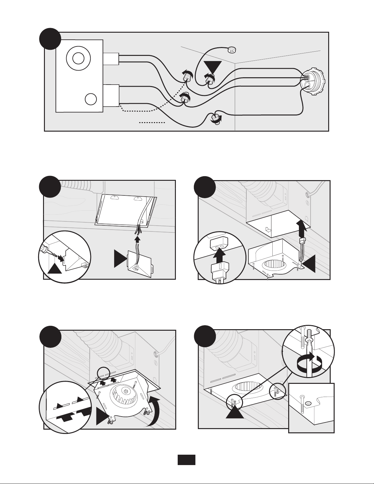
D16
Main Switch 1 (AC In)
Switch 2 (AC In)
*Option Fan & Main Light Together
*Option
F
D17
G
Connect wires as shown.
Install the wiring cover plate.
Reinstall the motor by inserting the tabs and pushing
up into position. Make sure the wires are not pinched
between the motor and the housing.
Connect wiring from the motor to the wiring cover
Secure the motor by tightening the 2 screws.
16
43033-01 01/24/2008
plate.
ON
OFF
D22
D23
E1
Go to step
on page 17
to attach grille.
D21
K
E1
Turn on the power source.
L
E2
Attaching the Dome Assembly
Test the motor. If the motor does not run, check the
plug connection.
Remove the thumbscrews.
Connect wiring harness.
17
43033-01 01/24/2008
E6
E8
E7
M
E4
J
E5
Remove the strain relief bracket screw.
E3
K
Position the strain relief bracket under the motor as
shown.
Insert the strain relief bracket’s dog-leg tab so that it
hooks over the lip of the motor. Reinstall the strain
relief bracket screw.
Attach thumbscrews.
WARNING: To reduce the risk of electrical shock,
all 4 thumbscrews MUST be properly installed.
43033-01 01/24/2008
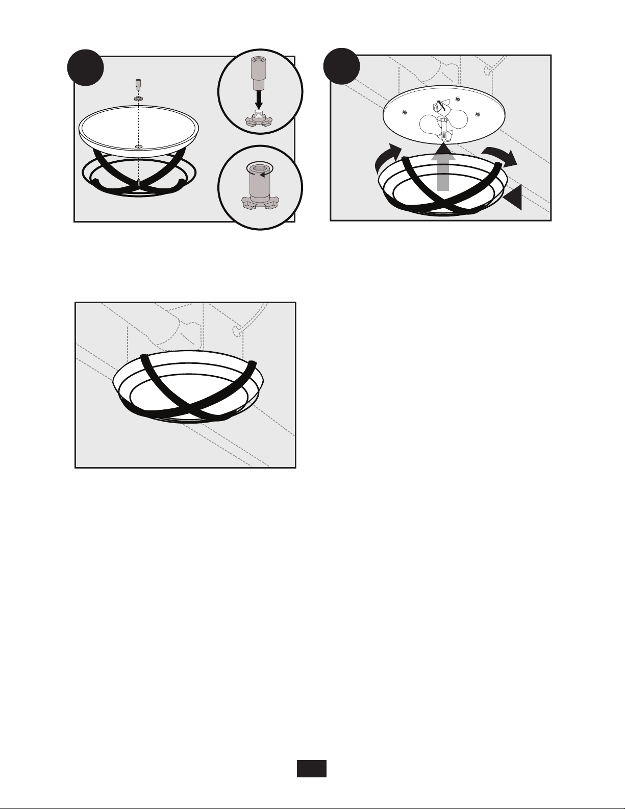
Align posts A, B, C and D (stamped into motor housing)
with posts A, B, C and D (stamped into light fixture).
Slide light fixture over posts.
Install 2 Max 60 Watt A15 bulbs (Not Included).
18
L
E10
Assemble the grille, glass dome, washer, and barrel
E9
nut as shown. Tighten the barrel nut “finger-tight.”
NOTE: The washer must be oriented as shown.
Complete.
Screw the dome assembly dome into position.
43033-01 01/24/2008
19

Trouble Shooting
Problem: Fan does not come on.
Solution:
• Harbor Breeze Fan Bath Ventilators are extremely quiet. To conrm that the fan is running, place
your hand near the vents to feel the air movement.
• Turn power on, replace fuse, or reset breaker.
• Check all plug connections to be sure they are secure.
• Check the wiring to make sure it matches the wiring diagram.
Problem: Light does not come on.
Solution:
• Replace the light bulb with a new bulb.
• Turn power on, replace fuse, or reset breaker.
• Check all plug connections to be sure they are secure.
• Check the wiring to make sure it matches the wiring diagram.
Problem: Fan is noisy.
Solution:
• Check and tighten all fasteners.
• Check the glass to make sure it is secure.
• Check the apper to make sure it moves freely.
If you need parts or service assistance, please call 866-405-3814.
20
43033-01 01/24/2008
 Loading...