

Page 1

The Garden District Collection
Bath Ventilator with Light
English
Español
Página 21
43053-01
20110908
©2011 Hunter Fan Co.
Owner’s Manual
Model
80707
Page 2

WARNING
!
TO REDUCE THE RISK OF FIRE, ELECTRIC SHOCK, OR
INJURY TO PERSONS, OBSERVE THE FOLLOWING:
1. Use this unit only in a manner intended by the manufacturer. If you
have questions, contact the manufacturer.
2. Before servicing or cleaning the unit, switch power off at service
panel and lock the service disconnecting means to prevent
power from being switched on accidentally. when the service
disconnecting means cannot be locked, securely fasten a prominent
warning device, such as a tag, to the service panel.
3. Installation work and electrical wiring must be done by qualified
person(s) in accordance with all applicable codes and standards,
including fire-rated construction.
4. Sufficient air is needed for proper combustion and exhausting of
gasses through the flue (chimney) of fuel burning equipment to
prevent backdrafting. Follow the heating equipment manufacturer’s
guideline and safety standards, such as those published by the
National Fire Prevention Association (NFPA), and the American
Society for Heating, Refrigeration and Air-Conditioning Engineers
(ASHRAE), and the local code authorities.
5. When cutting or drilling into wall(s) or ceiling, do not
damage electrical wiring or other hidden utilities.
6. Ducted fans must always be vented to the outdoors.
7. If this unit is to be installed over a tub or shower, it must be marked
as appropriate for the application and be connected to a GFCI
(Ground Fault Circuit Interrupter) - protected branch circuit.
8. Never place a switch where it can be reached from a tub or shower.
9. Install fan at least 5 feet (1.52 m) above the floor.
10. This unit must be grounded.
11. Unit must not be installed in a ceiling thermally insulated to a value
greater than R40.
MAINTENANCE
The motor is permanently lubricated and never needs oiling. If the
motor bearings are making excessive or unusual
noises, replace the motor with the exact service motor. You should
replace the impeller at the same time.
WARNING
!
DISCONNECT ELECTRIC
POWER SUPPLY
AND LOCK OUT
SERVICE PANEL BEFORE
SERVICING UNIT
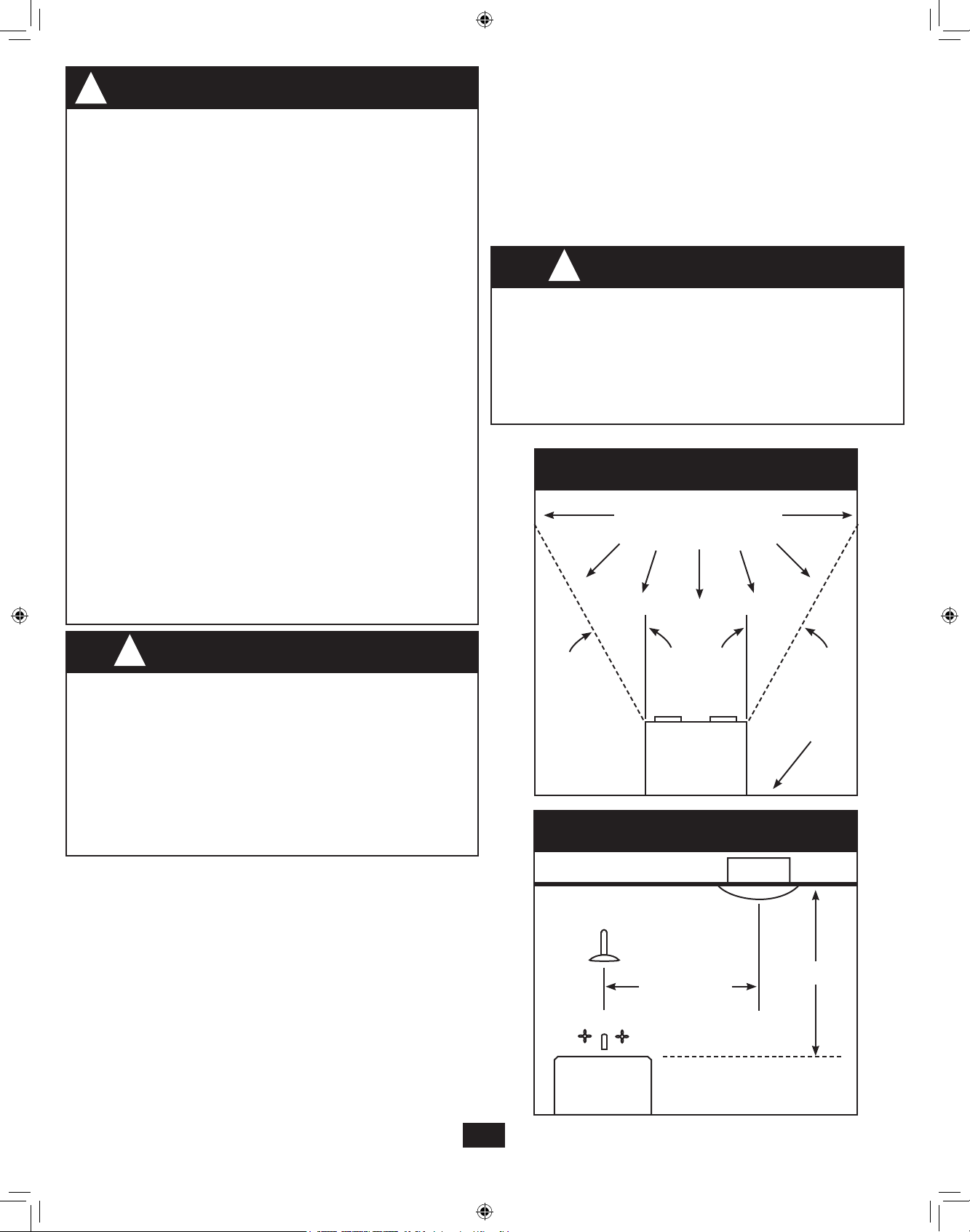
COOKING AREA
Do Not Install Above
Or Inside This Area
!
1. For general ventilating use only. Do not use to exhaust
hazardous or explosive materials and vapors.
2. To avoid motor bearing damage and noisy/unbalanced
impellers, keep drywall spray, construction dust, etc. off power
unit.
3. DO NOT install this product in a wall. This product is designed
for installation in ceilings up to a 12/12 pitch (45 degrees).
Ductwork must point upward.
4. Please read specification label on product for further
information and requirements.
CAUTION
PREVENTATIVE MAINTENANCE
A clean fan provides better service. Disconnect the power supply and
clean the fan as listed below.
TO CLEAN GRILL : Use a mild detergent, such as
dishwashing liquid, and a soft cloth. DO NOT use abrasive cloths,
steel wool pads or scouring powders.
TO CLEAN FAN ASSEMBLY: Unplug motor cord from receptacle. To
remove motor plate, find the single tab on the motor plate (located
next to the receptacle). Push up rear motor plate tab while pushing out
on the side of the housing or insert a screwdriver into the slot in the
housing (next to tab) and twist screwdriver. Gently vacuum fan, motor
and interior of housing.
METAL AND ELECTRICAL PARTS SHOULD NEVER BE IMMERSED
IN WATER.
45° 45°
Floor
Cooking
Equipment
BATHROOM AREA
Bath Fan
8ft. min.
3ft. min.
Tub /
Shower
2
43053-01 - 09/12/2011
Page 3
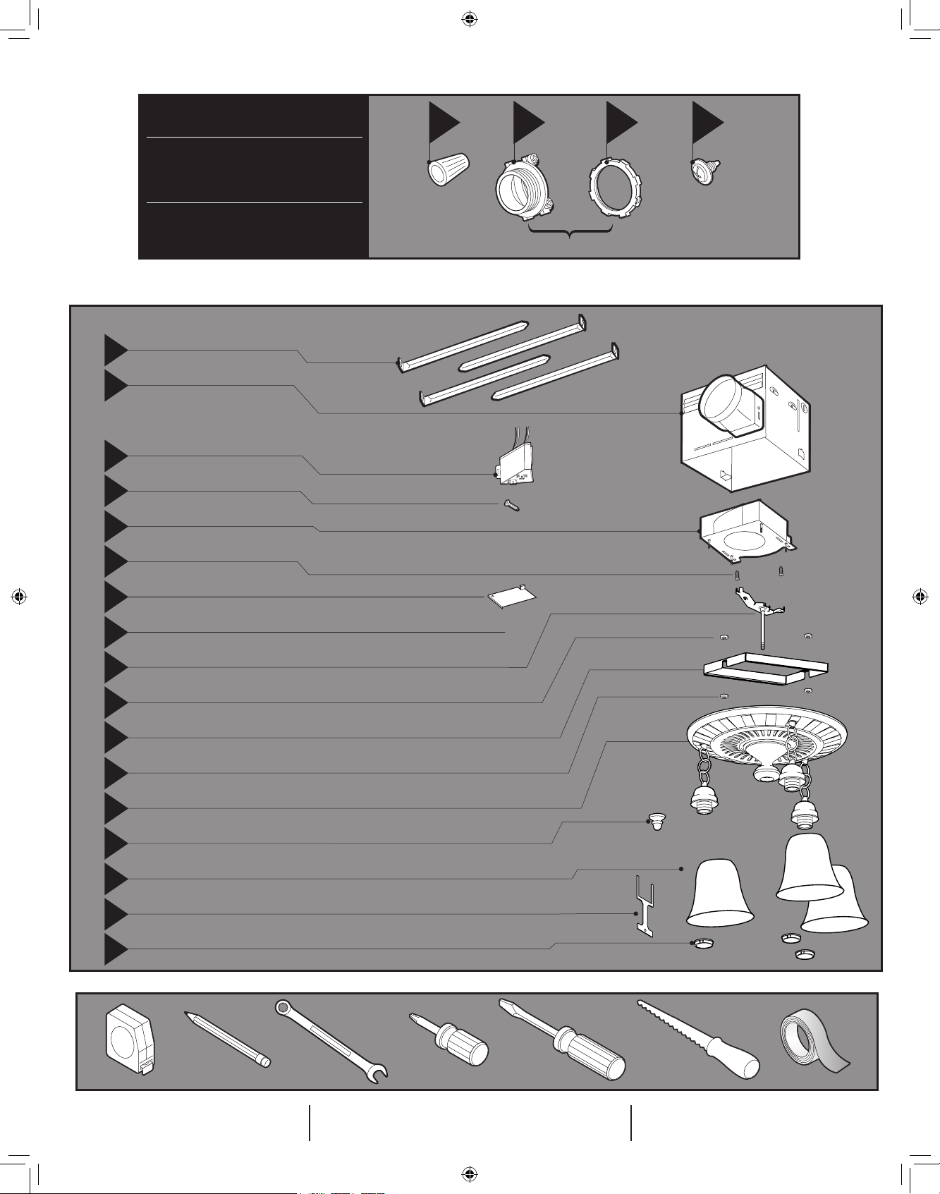
95044-01-000
D
95029-01-000
E
77481-01-000
F
03242-07-133
G
98624-01-000
H
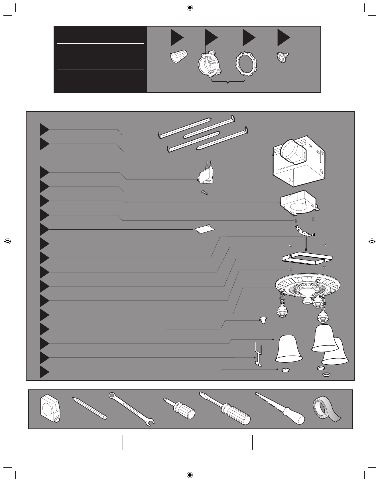
Check all the parts. If damaged, call
1-888-830-1326 for replacements.
*
NOTE: Strain relief cable connector must be installed. Not Included.
x4
x2
x2
A
B
B
B
*
*
*
3/8” Cable Connector
*
*
*
C
C
C
x2
I
I
I
Extra Screws
x2
x2
x2
74508-53-000
I
77521-01-000
J
74508-53-000
K
98447-02-000
L
66534-01-000
M
98617-01-000
N
66534-01-000
O
98519-02-000
P
77480-01-218
Q
88401-02-000
R
65517-01-000
S
88432-01-000
T
Not included
Tools Needed.
Estimated assembly time:
30 to 60 minutes
Page 4

Before Installation
NOTE: Remove all packing materials before installation.
1
3
2
I
H
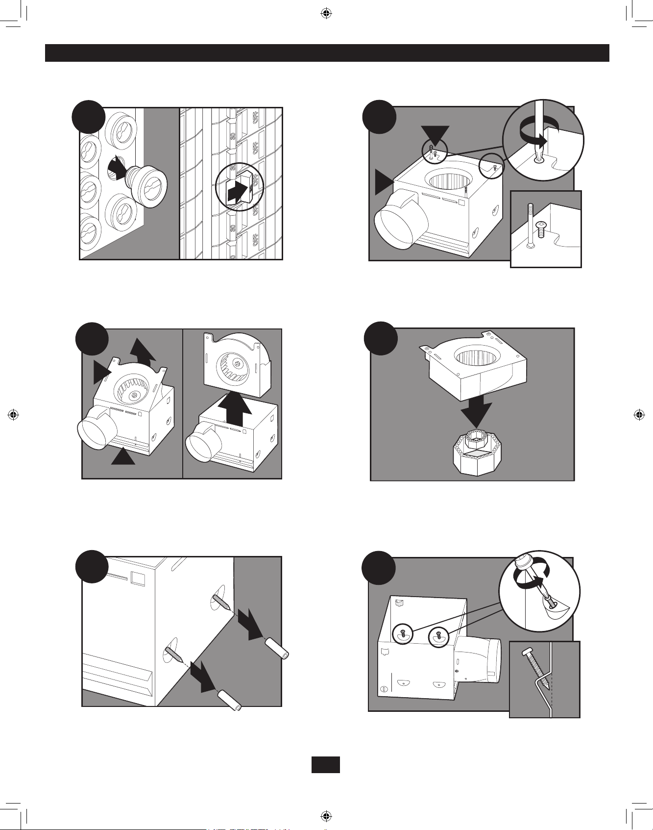
Turn off the power source.
Loosen screws.
4
H
I
5
E
Remove the motor/blower from the housing.
Remove the pre-loaded screw tip covers.
Remove packing material.
6
Back out the pre-loaded screw tips until flush with the side
of the housing.
4
43053-01 - 09/12/2011
Page 5
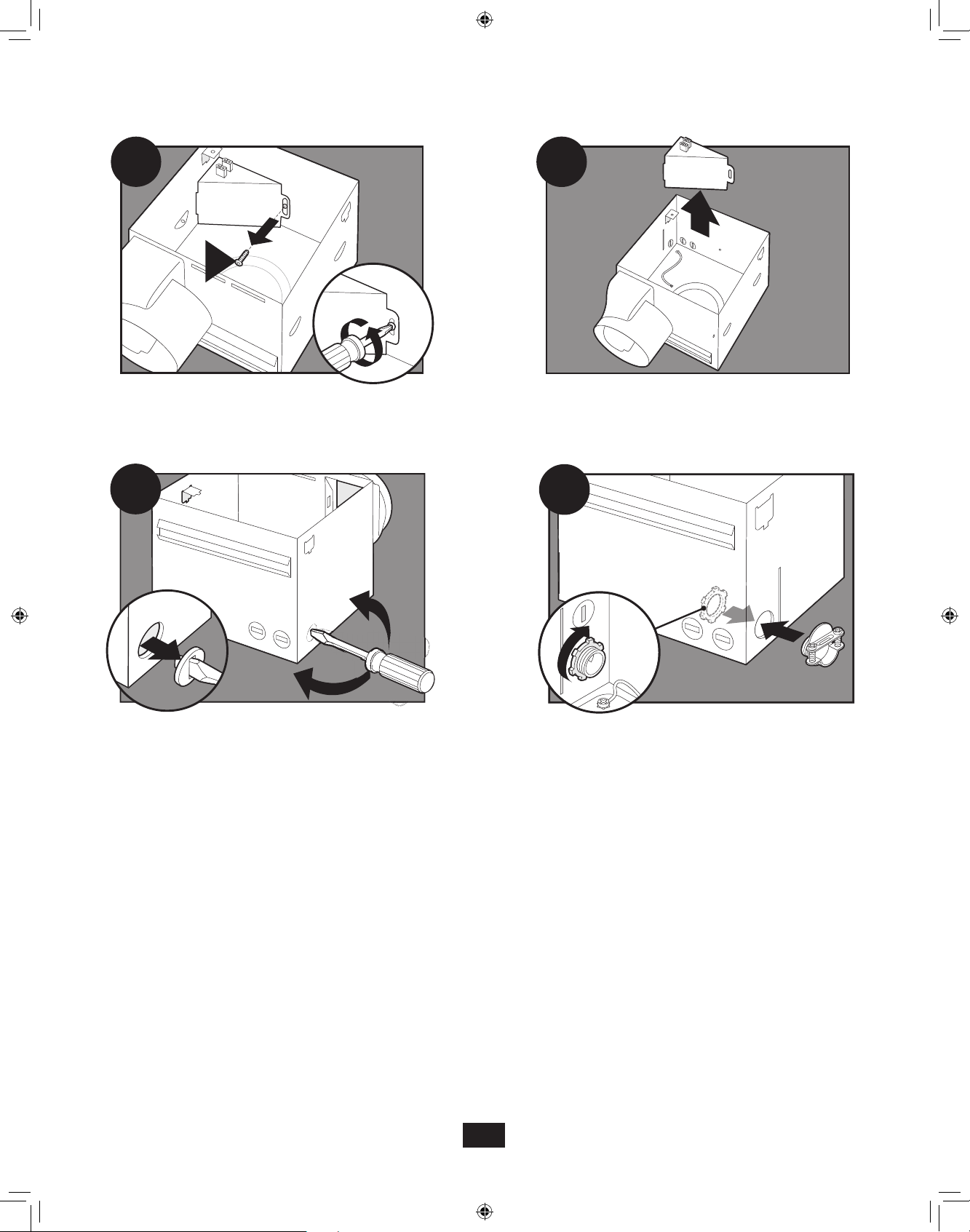
7
8
Remove the wiring cover screw.
9
Pop out the first wiring access slug. Use second if needed.
10
Remove the wiring cover.
B
Insert the strain relief into the housing and
secure with the washer.
Choose Installation Option
For New Construction - attaching to joist go to step A11, page 7
For New Construction - suspended between joists go to step B11, page 9
For Existing Construction - accessible from above go to step C11, page 12
For Existing Construction - accessible only from below go to step D11, page 16
5
43053-01 - 09/12/2011
Page 6
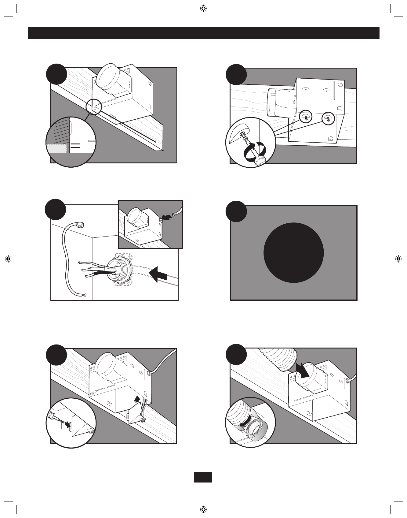
New construction attaching to joist
A11
5/8
1/2
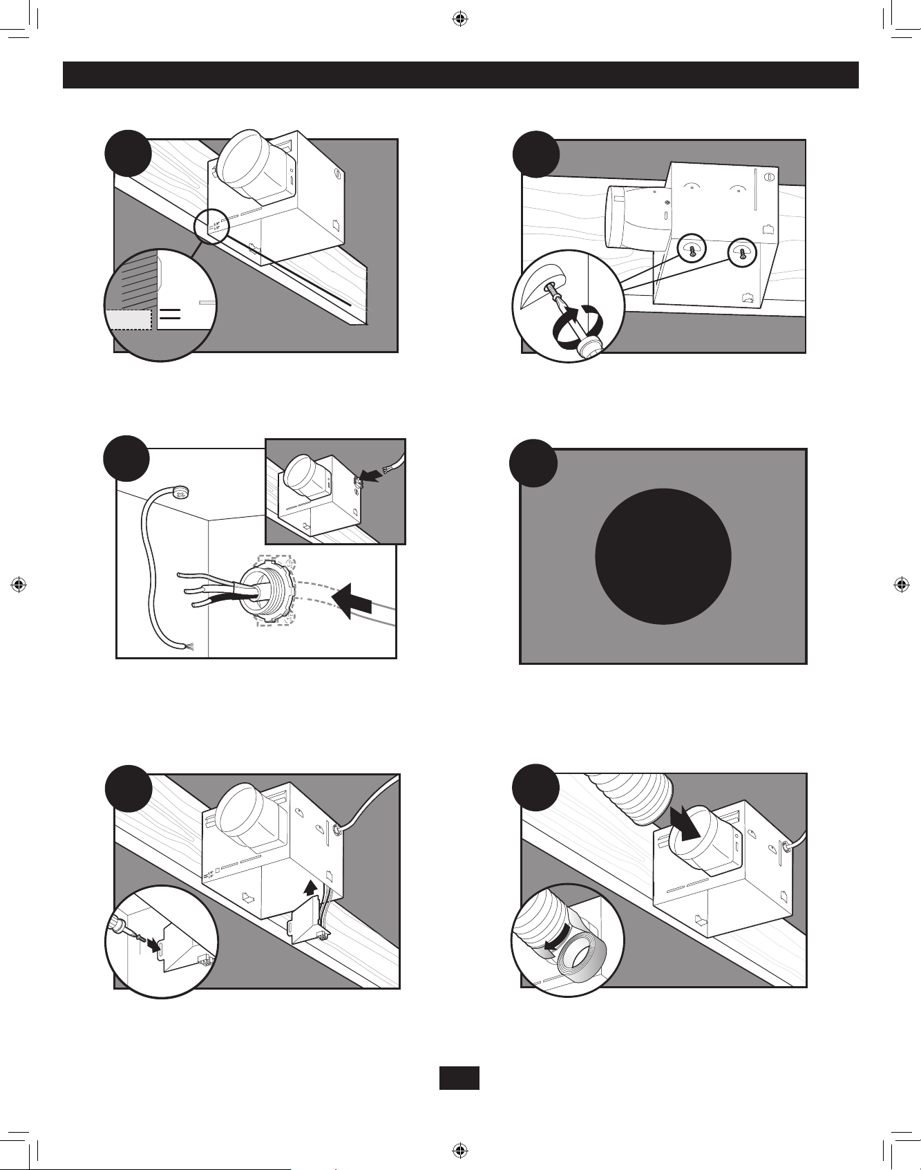
Position the correct depth mark at the bottom edge of
the joist based on the thickness of your sheetrock.
A13
A12
Screw pre-loaded screws into joist or framing.
A14
A15
Pull wires through the strain relief.
F1
Go to step F1 on page 20 to connect the wires as shown.
A16
0
Install the wiring cover plate. Make sure all wiring connections
are inside the box or under the wiring cover plate.
Connect 4” duct and vent to the outside. Tape joints.
If ducting does not fit securely, an adapter may need
to be purchased.
6
43053-01 - 09/12/2011
Page 7
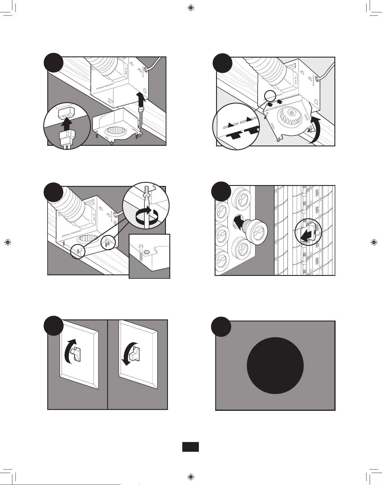
ON
OFF
0000
A17A17
0000
A17
A18
Connect wiring from the motor to the wiring cover plate.
A19
Secure the motor by tightening the 2 screws.
Reinstall the motor by inserting the tabs and pushing up into
position. Make sure the wires are not pinched between the
motor and the housing.
A20
Turn on the power source.
A21
Test the motor. If the motor does not run, check the
plug connection.
A22
E1
Go to step E1 on page 18 to attach grill.
7
43053-01 - 09/12/2011
Page 8
5/8
1/2
1/8" Bit
New construction suspended between joist
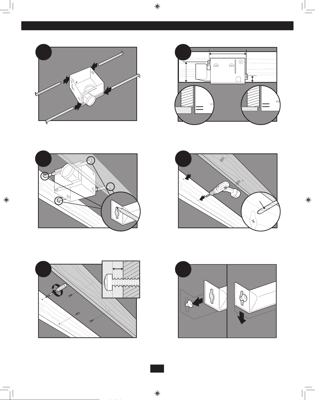
B11
B13
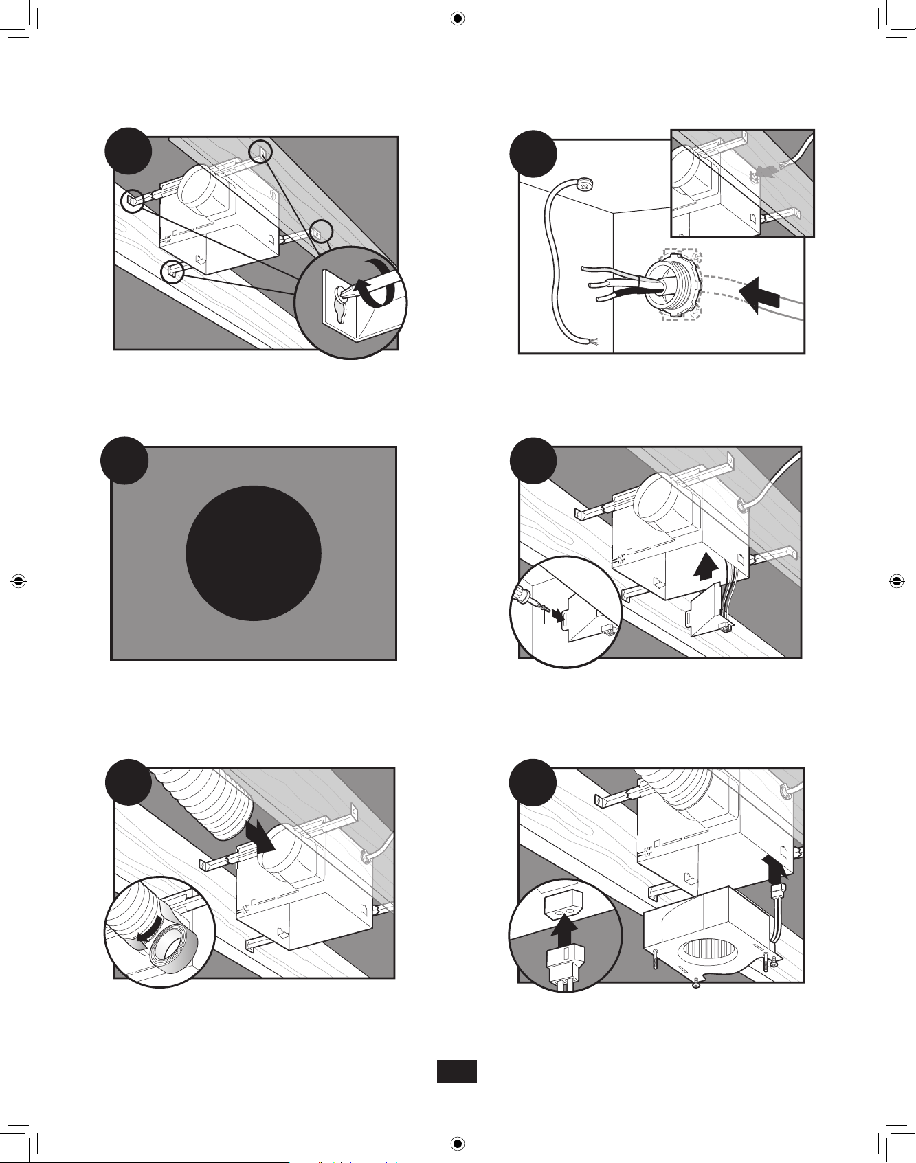
Slide the mounting rails into brackets.
B12
5/8
1/2
Position the correct depth mark at the bottom edge of the
joist based on the thickness of your sheetrock.
B14
Mark position of screws by using holes as a template.
B15
Insert screws, leaving space between the screw head and the
joist. Screws are not provided.
Drill a hole in the center of each outline.
B16
Attach the rails onto the screws.
8
43053-01 - 09/12/2011
Page 9

B17
B18
Tighten screws.
B19
F1
Go to step F1 on page 20 to connect the wires as shown.
Install the wiring cover plate. Make sure all wiring
connections are inside the box or under the wiring cover plate.
B20
Install the wiring cover plate. Make sure all wiring connections
are inside the box or under the wiring cover plate..
B21
Connect 4” duct and vent to the outside. Tape joints. If ducting
does not fit securely, an adapter may need to be purchased.
B22
Connect wiring from the motor to the wiring cover plate.
9
43053-01 - 09/12/2011
Page 10
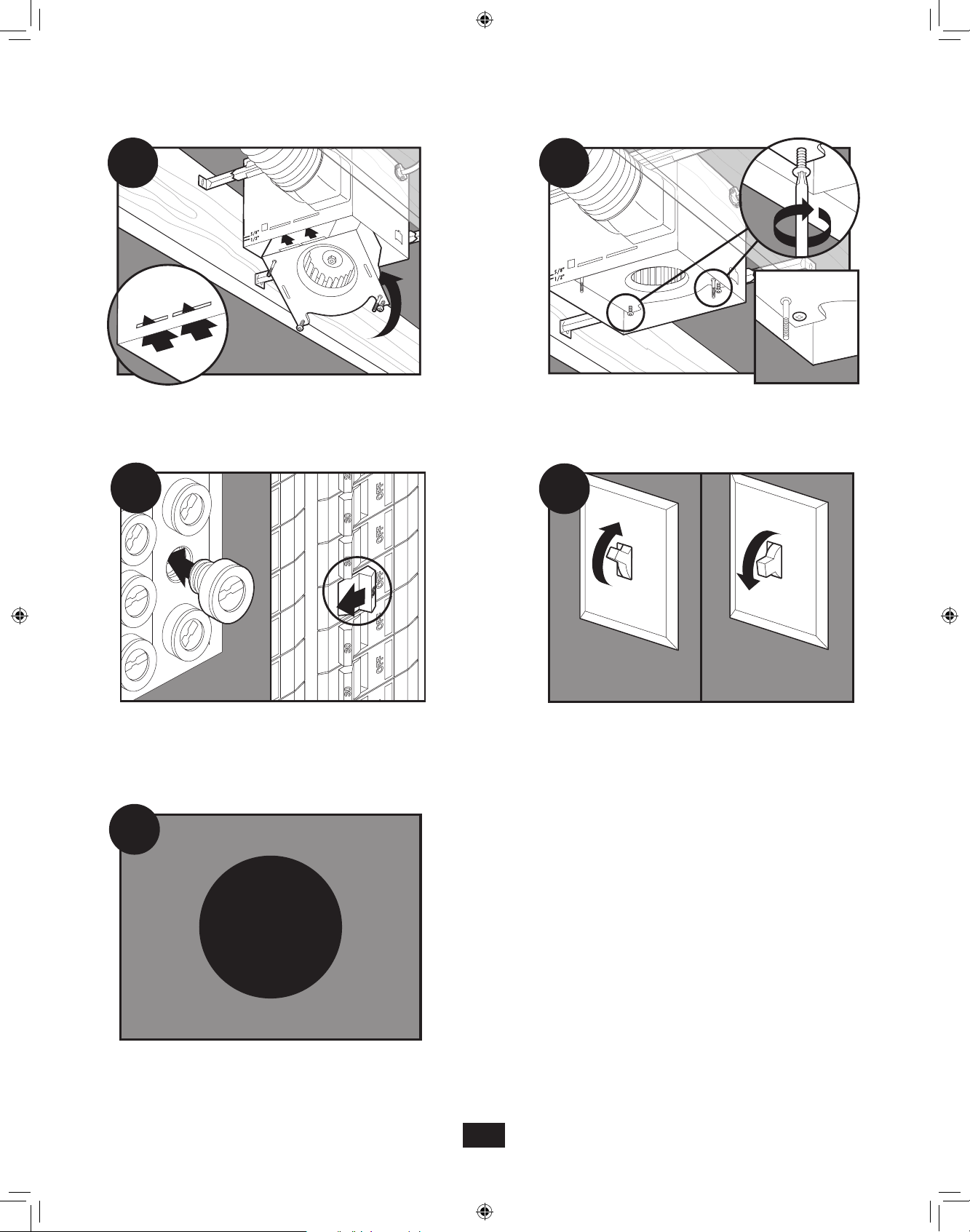
B23
ON
OFF
B24
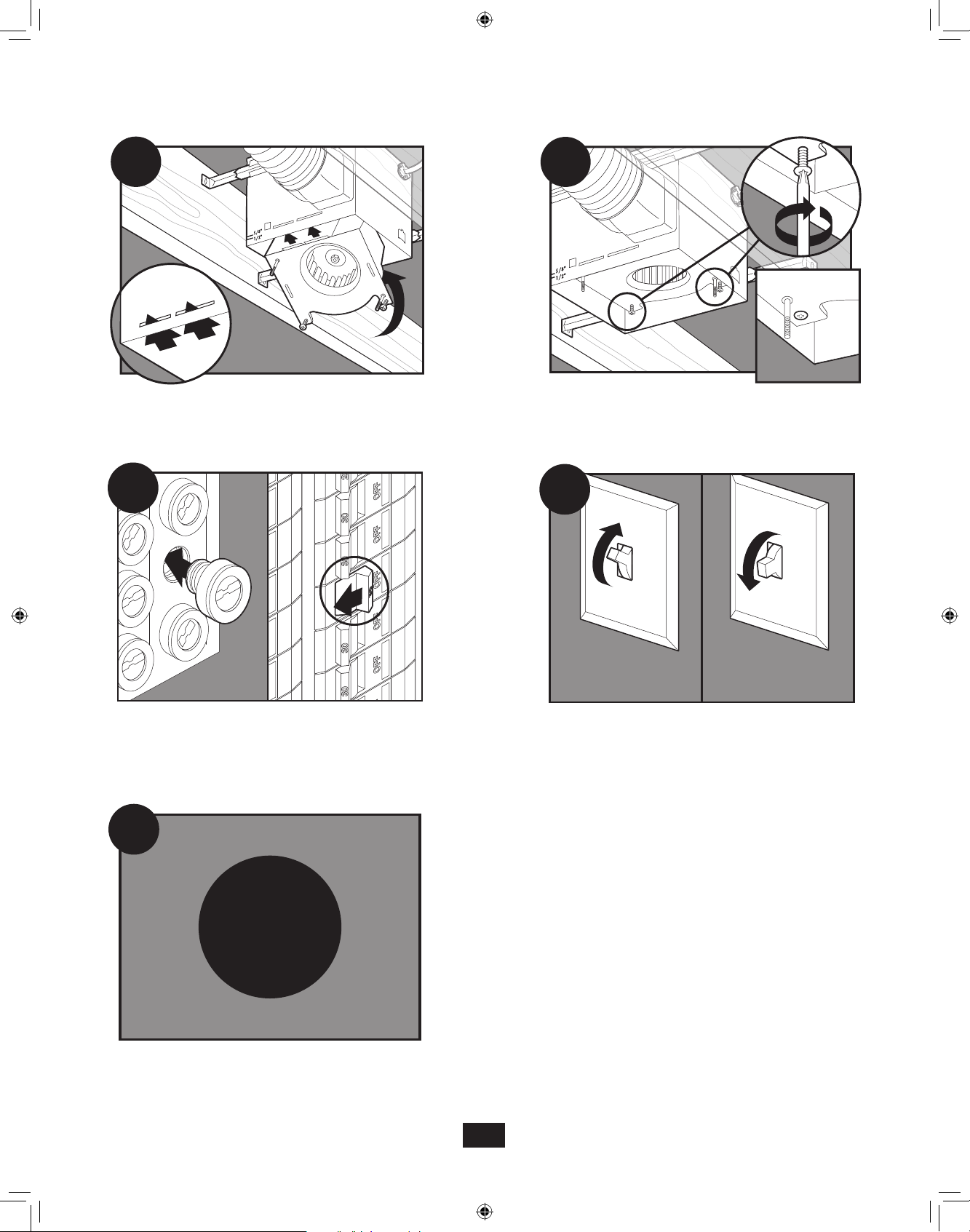
Reinstall the motor by inserting the tabs and pushing up into
position. Make sure the wires are not pinched between the
motor and the housing.
B25
Turn on the power source.
Secure the motor by tightening the 2 screws.
B26
B26
Test the motor. If the motor does not run, check the
plug connection.
B27
E1
Go to step E1 on page 18 to attach grill.
10
43053-01 - 09/12/2011
Page 11
Existing construction accessible from above
5/8
1/2
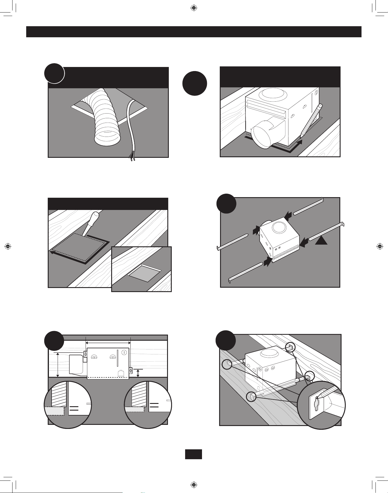
C11
Remove an existing fan and check to make sure the opening is
large enough to accommodate the new motor housing (8”x 8.5”).
EXISTING FAN
NO EXISTING FAN
OR
Use the motor housing as a template to mark position.
C12
C13
8”
8.5”
Cut out an opening for the housing.
5/8
1/2
Slide the mounting rails into brackets.
C14
Position the correct depth mark at the bottom edge of the joist
based on the thickness of your sheetrock.
Mark position of screws by using holes as a template.
11
43053-01 - 09/12/2011
Page 12
C15
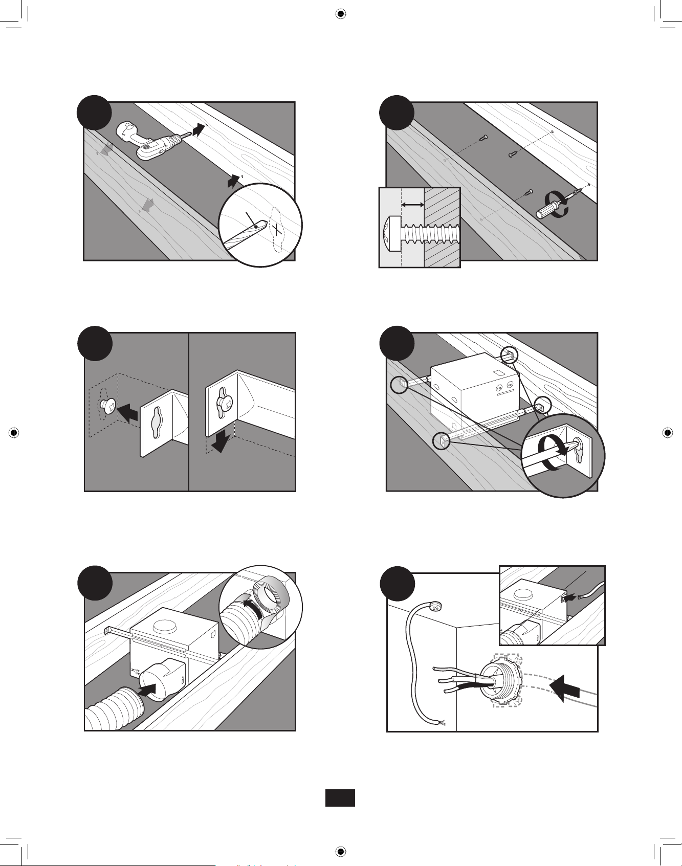
C16
1/8" Bit
C17
Drill a hole in the center of each outline.
Attach the rails onto the screws.
Insert screws, leaving space between the screw head and the
joist. Screws are not provided.
C18
Tighten screws.
C19
Connect 4” duct and vent to the outside. Tape joints. If ducting
does not fit securely, an adapter may need to be purchased.
C20
Pull wires through the strain relief.
12
43053-01 - 09/12/2011
Page 13
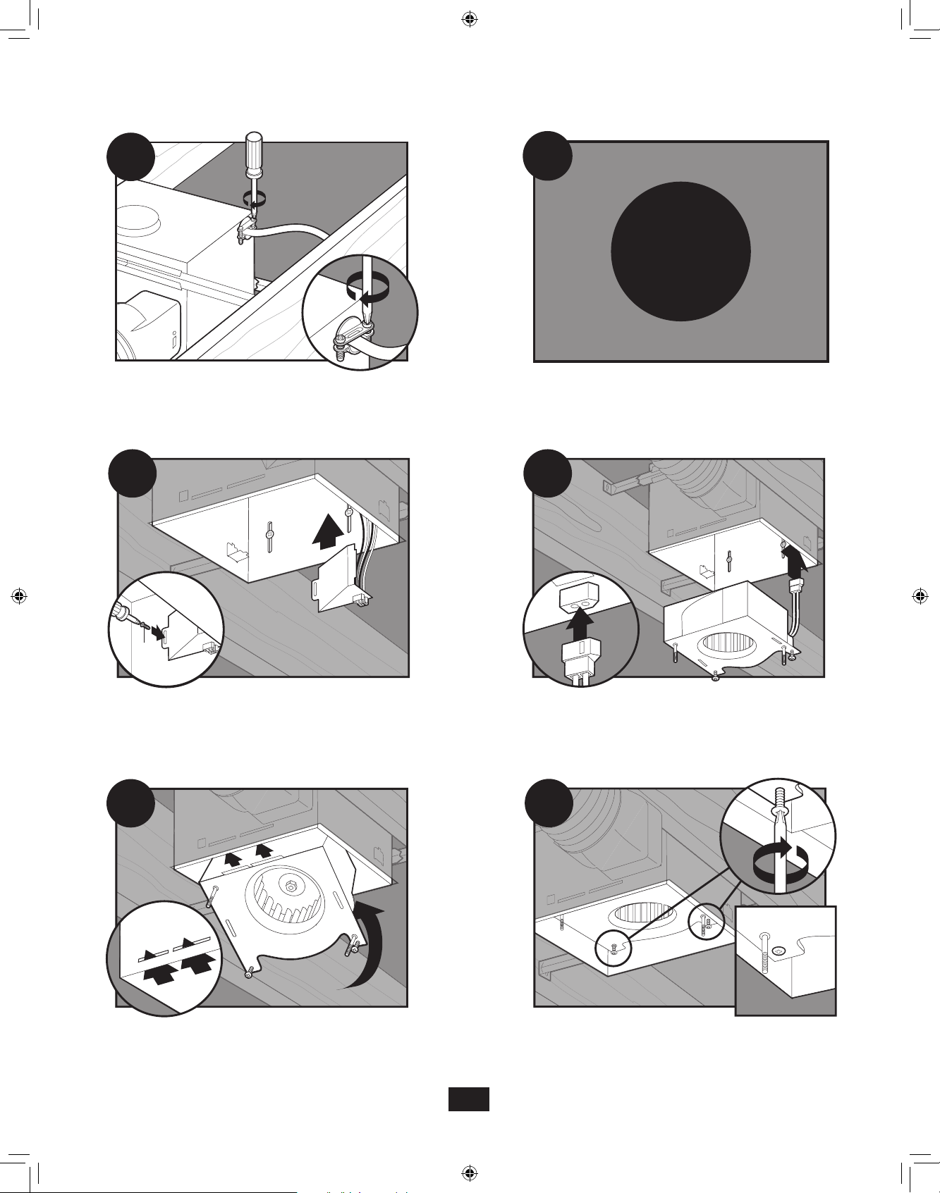
C21
C22
F1
Tighten the strain relief screws.
C23
Install the wiring cover plate. Make sure all wiring connections
are inside the box or under the wiring cover plate.
Go to step F1 on page 20 to connect the wires as shown.
C24
Connect wiring from motor the motor
to the wiring cover plate.
C25
Reinstall the motor by inserting the tabs and pushing up into
position. Make sure the wires are not pinched between the motor
and the housing.
C26
Secure the motor by tightening the 2 screws.
13
43053-01 - 09/12/2011
Page 14
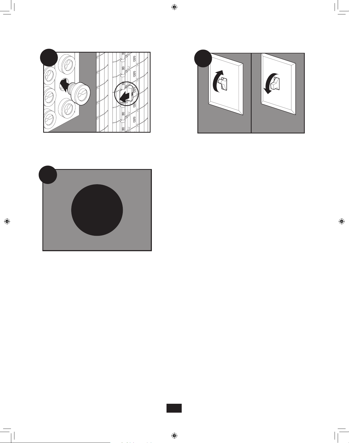
C27
ON
OFF
C28
C28
C29
Turn on the power source.
E1
Go to step E1 on page 18 to attach grill.
Test the motor. If the motor does not run, check the
plug connection.
14
43053-01 - 09/12/2011
Page 15
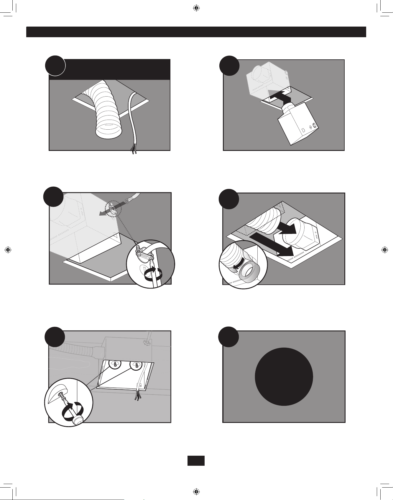
Existing construction accessible only from below
D11
Remove an existing fan and check to make sure the opening is
large enough to accommodate the new motor housing (8”x 8.5”).
EXISTING FAN
D13
D12
Move the housing into position above the ceiling.
D14
2
D15
Pull wires through strain relief.
1
Attach existing ducting to duct connector. Tape joints. If ducting
does not fit securely, an adapter may need to be purchased.
D16
F1
Install the housing flush with the sheetrock and secure by
tightening the pre-loaded screws into the joist.
Go to step F1 on page 20 to connect the wires as shown.
15
43053-01 - 09/12/2011
Page 16
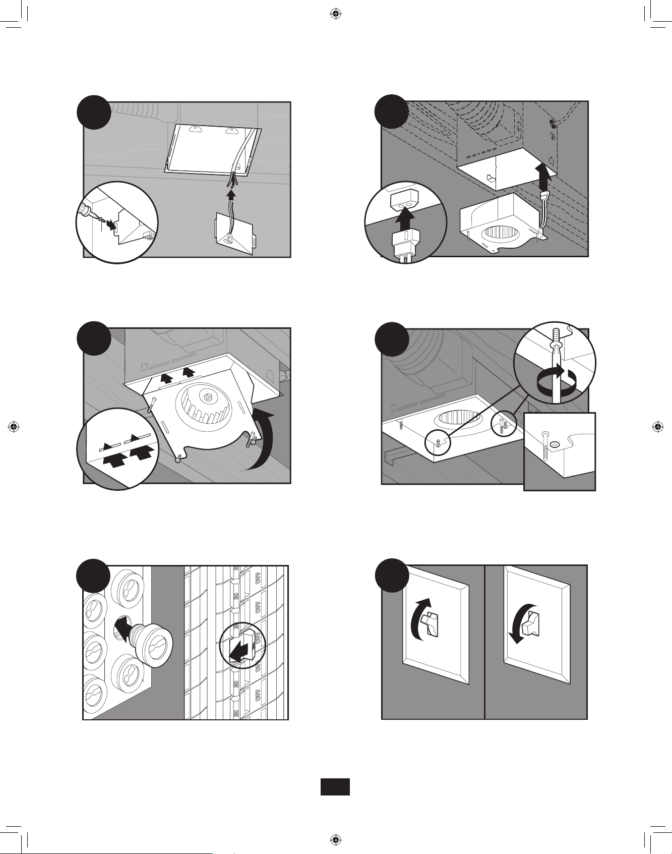
D17
ON
OFF
D18
Install the wiring cover plate.
D19
Reinstall the motor by inserting the tabs and pushing up into
position. Make sure the wires are not pinched between the
motor and the housing.
Connect wiring from the motor to the wiring cover plate.
D20
Secure the motor by tightening the 2 screws.
D21
Turn on the power source.
D22
16
43053-01 - 09/12/2011
D22
Test the motor. If the motor does not run, check the
plug connection.
Page 17

Attaching the grill
NOTE: The grill’s size, shape, and number of lights may vary.
E1
E3
Remove the two star nuts.
E2
Align posts B and D (stamped into motor housing) with posts B
and D (stamped into light fixture). Slide support bar and hiding
plate onto posts.
E4
[a]
Feed the mounting cable through the hiding plate, then attach
mounting cable [a] to the support bracket.
E5
Plug in wiring harness.
E6
Insert the strain relief bracket’s dog-leg tab so that it hooks over
the lip of the motor. Reinstall the strain relief bracket screw.
43053-01 - 09/12/2011
Raise the bezel onto the threaded rod of the support bracket.
17
Page 18
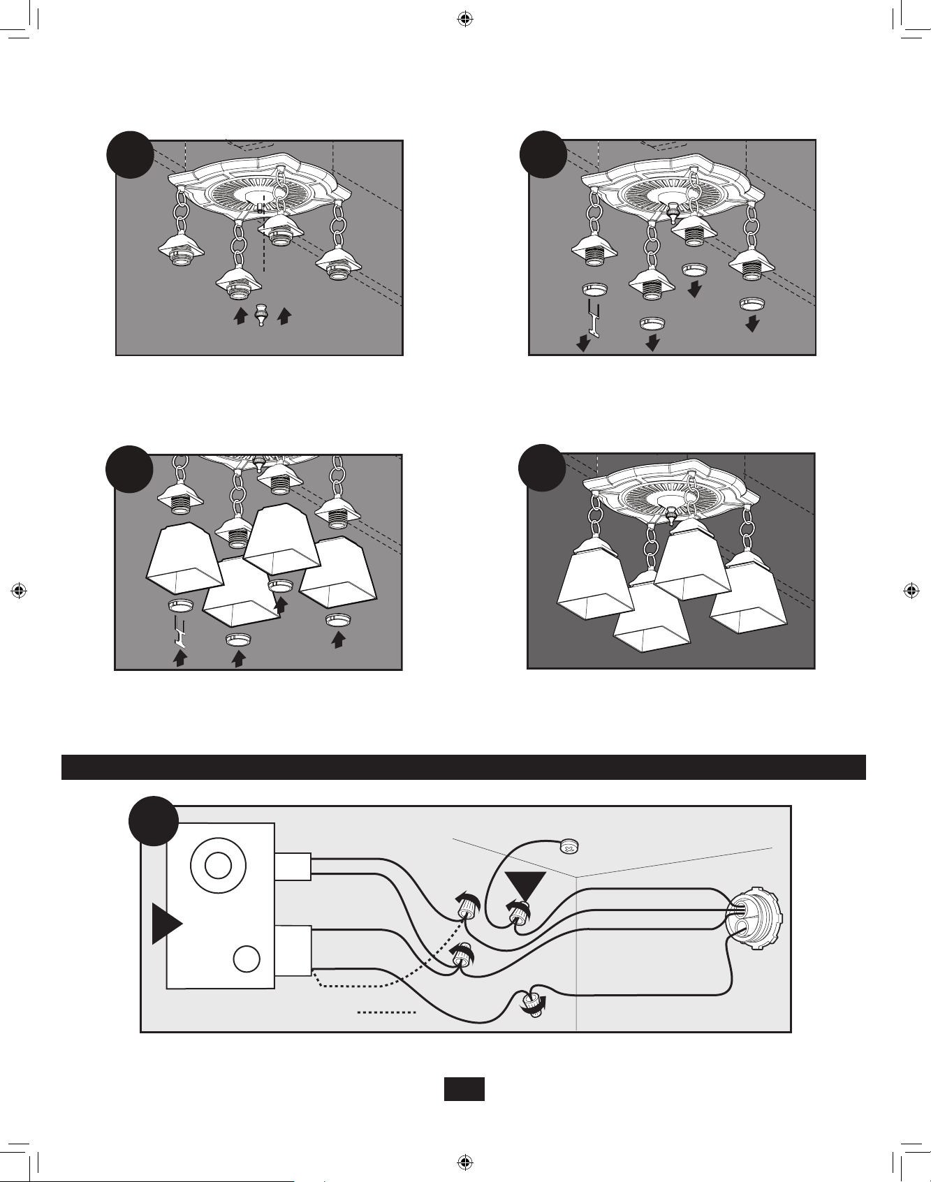
E7
E8
Screw finial onto the threaded rod of the support bracket.
E9
Place the glass onto the sockets and re-install the glass
retaining rings using the glass ring tool.
Unscrew glass retainer ring using the glass ring tool provided.
E10
Complete.
Wiring the fan
F1
Fan Motor
F
Light
*Option Fan & Main Light Together
2 Pin
3 Pin
Black
White
White
Black Light
*Option
Ground
Green
A
Connect wires as shown.
18
43053-01 - 09/12/2011
Bare Copper
Black Main Switch 1 (AC In)
White
Black Switch 2 (AC In)
Page 19
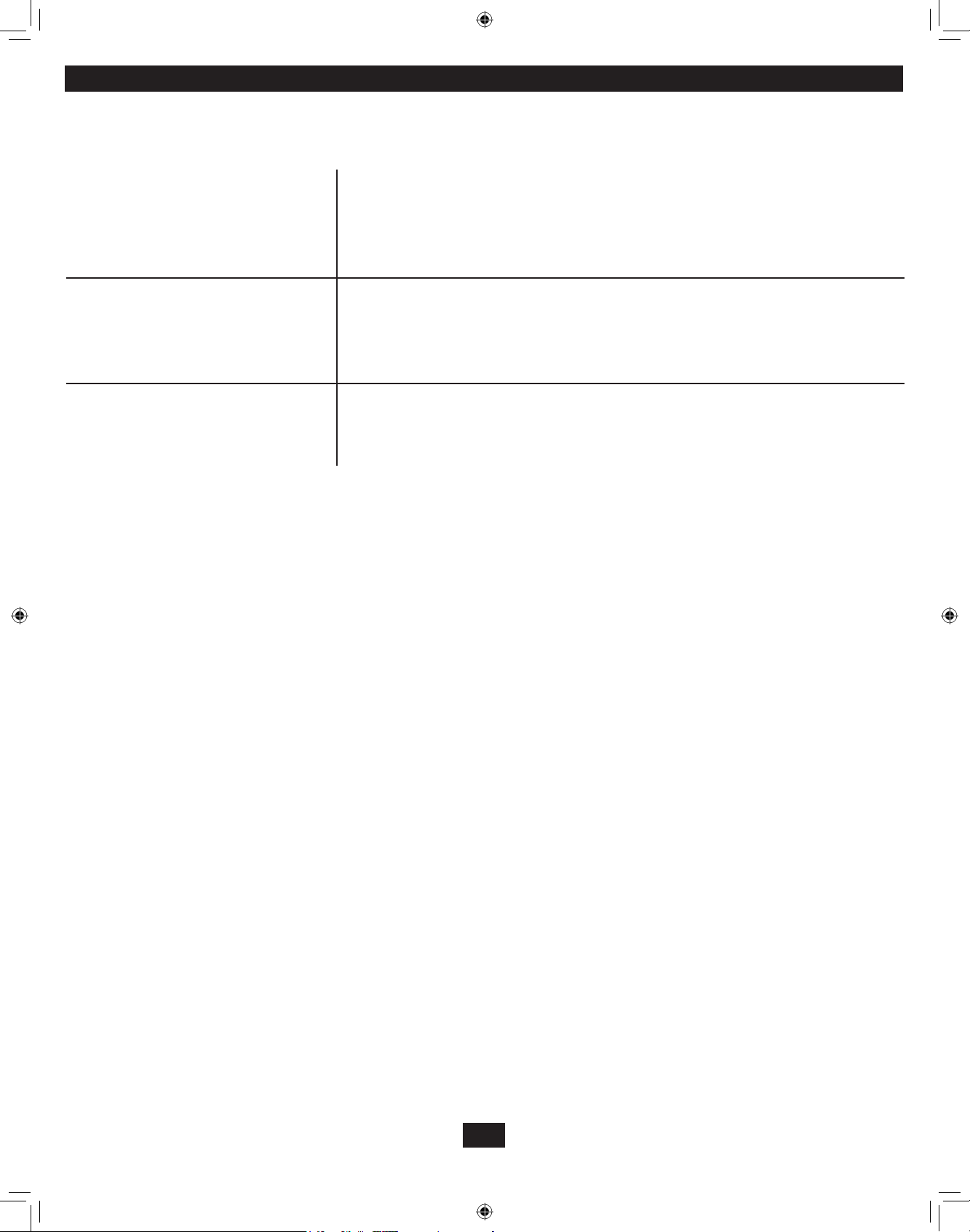
Trouble Shooting
Problem: Fan does not come on.
Problem: Light does not come on.
Problem: Fan is noisy.
If you need parts or service assistance, please call 888-830-1326
Solution:
• Hunter Fan Bath Ventilators are extremely quiet. To conrm that the fan is
running, place your hand near the vents to feel the air movement.
• Turn power on, replace fuse, or reset breaker.
• Check all plug connections to be sure they are secure.
• Check the wiring to make sure it matches the wiring diagram.
Solution:
• Replace the light bulb with a new bulb.
• Turn power on, replace fuse, or reset breaker.
• Check all plug connections to be sure they are secure.
• Check the wiring to make sure it matches the wiring diagram.
Solution:
• Check and tighten all fasteners.
• Check the glass to make sure it is secure.
• Check the apper to make sure it moves freely.
19
43053-01 - 09/12/2011
Page 20

Warranty
Hunter Fan
Bath Exhaust Fan
LIMITED WARRANTY
The manufacturer makes the following limited warranty to the original user or consumer purchaser of this Hunter Fan bath exhaust fan:
If any part of your Hunter Fan bath exhaust fan (except for glass xtures and light bulbs) fails at any time within one year after the date of sale
to you due to a defect in material or workmanship, we will repair or, at our option, replace the defective part free of charge. After this one-year
period, you will be responsible for all parts and labor costs for repairs on the bath exhaust fan except for motor repairs as provided below.
If your Hunter Fan bath exhaust fan motor fails at any time within ve years after the date of sale to you due to a defect in material or workmanship, labor and materials to repair the defect will be provided free of charge. If no replacement part can be provided, we will, at our option,
either refund the actual purchase price of your bath exhaust fan or provide a replacement free of charge. After this ve-year period, you will be
responsible for all parts and labor costs for repairs on all parts of the bath exhaust fan.
IF THE ORIGINAL USER OR CONSUMER PURCHASER CEASES TO OWN THE FAN, THIS WARRANTY AND ANY IMPLIED WARRANTY
WHICH THEN REMAINS IN EFFECT, INCLUDING BUT NOT LIMITED TO ANY IMPLIED WARRANTY OF MERCHANTABILITY OR FITNESS
FOR A PARTICULAR PURPOSE, ARE VOIDED. NO WARRANTY, EXPRESS OR IMPLIED, INCLUDING ANY WARRANTY OF MERCHANTABILITY OR FITNESS FOR A PARTICULAR PURPOSE, IS MADE IN RESPECT OF GLASS FIXTURES OR LIGHT BULBS OR THE FINISH
ON ANY METAL PORTION OF THE BATH EXHAUST FAN.
THIS WARRANTY IS IN LIEU OF ALL OTHER EXPRESS WARRANTIES. THE DURATION OF ANY IMPLIED WARRANTY, INCLUDING,
BUT NOT LIMITED TO, ANY IMPLIED WARRANTY OF MERCHANTABILITY OR FITNESS FOR A PARTICULAR PURPOSE, IN RESPECT
TO ANY HUNTER FAN FAN BATH EXHAUST FAN MOTOR OR OTHER FAN PART, IS EXPRESSLY LIMITED TO THE PERIOD OF THE
EXPRESS WARRANTY SET FORTH ABOVE FOR SUCH MOTORS OR OTHER PARTS.
This warranty is voided if your Hunter Fan bath exhaust fan is not purchased and installed in the U.S.A. This warranty excludes and does not
cover defects, malfunctions or failures of any Hunter Fan bath exhaust fan which were caused by repairs by persons not authorized by us, use
of parts or accessories not authorized by us, mishandling, improper installation, modications or damage to the Hunter Fan bath exhaust fan
while in your possession, or unreasonable use, including failure to provide reasonable and necessary maintenance.
To obtain servicing, contact the Hunter Fan Service Department at1-866-405-3814. Please contact us before shipping your bath exhaust fan to
us. If we authorize you to ship it to us, you will be responsible for all insurance and freight or other transportation charges to our factory or service center. We will return your Hunter Fan bath exhaust fan freight prepaid. Your Hunter Fan bath exhaust fan should be properly packed to
avoid damage in transit since we will not be responsible for any such damage. Proof of purchase is required when requesting warranty service.
The purchaser must present the sales receipt or other document that establishes proof of purchase.
IN NO EVENT SHALL THE MANUFACTURER BE LIABLE FOR CONSEQUENTIAL OR INCIDENTAL DAMAGES.
SOME STATES DO NOT ALLOW LIMITATIONS ON HOW LONG AN IMPLIED WARRANTY LASTS OR THE EXCLUSION OR LIMITATION
OF INCIDENTAL OR CONSEQUENTIAL DAMAGES SO THE ABOVE LIMITATION OR EXCLUSIONS MAY NOT APPLY TO YOU.
THE WARRANTY GIVES YOU SPECIFIC LEGAL RIGHTS AND YOU MAY ALSO HAVE OTHER RIGHTS WHICH VARY FROM STATE TO
STATE.
Fan Company
7130 Goodlett Farms Pkwy Suite 400Memphis, TN 38016
20
43053-01 - 09/12/2011
© 2011 Hunter Fan Company
Page 21

The Garden District Collection
Ventilador para baño con luz
Español
43053-02
20110909
©2011 Hunter Fan Co.
Manual del Propietario
Modelo
80707
Page 22
ADVERTENCIA
!
PARA REDUCIR EL RIESGO DE INCENDIO, CHOQUE ELÉCTRICO
O LESIONES A PERSONAS, OBSERVE LO SIGUIENTE:
1. Utilice esta unidad sólo de la manera indicada por el fabricante. Si
tiene alguna pregunta, contacte con el fabricante.
2. Antes de dar servicio o limpiar la unidad, desconecte la alimentación
en el tablero de servicio y bloquee los elementos de desconexión
a fin de evitar que la alimentación pueda ser conectada
accidentalmente. Cuando los elementos de desconexión no pueden
ser bloqueados, asegure firmemente una forma destacada de
advertencia, como una etiqueta, en el tablero de servicio.
3. Los trabajos de instalación y cableado eléctrico deben ser realizados
por personas calificadas de acuerdo con todos los códigos y las
normas aplicables, incluyendo el de diseño contra incendio.
4. Se necesita aire suficiente para una combustión adecuada y para
evacuar los gases por el tubo de la chimenea de equipo que quema
combustible a fin de evitar el flujo inverso. Siga las pautas del
fabricante del equipo de calefacción y las normas de seguridad,
como las de la Asociación Nacional de Protección contra Incendios
(NFPA), la Asociación de Ingenieros Americanos en Calefacción y
Aire acondicionado (ASHRAE), y los códigos locales.
5. “Al cortar o taladrar en paredes o techo, no
dañe el cableado eléctrico u otros servicios no visibles.”
6. Los ventiladores canalizados siempre deben descargar al aire libre.
7. Si va a instalar esta unidad en una bañera o ducha, debe tener
una marca que indique que es apropiado para ese uso y debe
conectarse a un circuito derivado protegido por un GFCI (interruptor
automático de falla a tierra).
8. Nunca coloque un interruptor donde pueda ser alcanzado desde
una tina o una ducha.
9. Instale el ventilador por lo menos a 5 pies (1.52 m) por encima del
piso.
10. Esta unidad se debe poner a tierra.
11. La unidad no debe ser instalada en un techo con aislamiento
térmico mayor que R40.
ventilador, el motor/soplador y el interior del alojamiento.
LAS PARTES METÁLICAS ELÉCTRICAS NUNCA DEBEN
SUMERGIRSE EN AGUA.
MANTENIMIENTO
El motor/soplador está lubricado permanentemente y no necesita
ser engrasado. Si los rodamientos del motor/soplador hacen ruidos
excesivos o inusuales, reemplace el motor/soplador con el motor/
soplador de servicio exacto. Debe reemplazar el impulsor al mismo
tiempo.
!
LA ALIMENTACIÓN ELÉCTRICA Y
CIERRE EL PANEL DE SERVICIO
ANTES DE DAR MANTENIMIENTO
ADVERTENCIA
DESCONECTE
A LA UNIDAD
ÁREA DE LA COCINA
No instale sobre o
dentro de esta área
45° 45°
!
1. Sólo para uso de ventilación general. No use para liberar
materiales y vapores peligrosos o explosivos.
2. Para evitar daños a los rodamientos del motor/soplador e impulsores ruidosos o desbalanceados, mantenga la unidad de
potencia lejos de la aplicación de aerosol para paneles de
yeso (drywall), polvo de la construcción, etc.
3. NO instale este producto en una pared. Este producto está diseñado para instalarse en techos con una inclinación de hasta
12/12 (45º). La red de ductos debe dirigirse hacia arriba.
4. Vea más información y los requisitos en la etiqu-
eta de especificación del producto.
PRECAUCIÓN
Mantenimiento Preventivo
Un ventilador limpio proporciona mejor servicio. Desconecte la
alimentación y limpie el ventilador como se indica a continuación.
PARA LIMPIAR LA REJILLA: Use un detergente suave, como líquido
para lavado de platos, y un paño suave. NO emplee paños abrasivos,
almohadillas de lana de acero ni polvos para fregar.
PARA LIMPIAR EL CONJUNTO DEL VENTILADOR: Desconecte el
cordón del motor/soplador de la toma de corriente. Para retirar la
placa del motor/soplador, encuentre la pestaña en la placa (ubicada
junto a la toma de corriente). Levante la pestaña posterior de la
placa del motor/soplador mientras empuja hacia afuera en el lado del
alojamiento o introduzca un destornillador en la ranura del alojamiento
(junto a la pestaña) y gire el destornillador. Suavemente aspire el
Equipo
Piso
de cocina
ÁREA DEL BAÑO
Ventilador para baño
Mín. 8 pies
Mín. 3 pies
Bañera /
Ducha
22
43053-02 - 09/14/2011
Page 23
Verique todos los componentes. Si
están dañados, llame al 1-866-405-3814
para obtener un reemplazo.
*
NOTA: Debe estar instalado el manguito de alivio de tensión del cable. No incluido.
95044-01-000
D
95029-01-000
E
77481-01-000
F
03242-07-133
G
98624-01-000
H
x4
x2
x2
A
B
B
B
*
*
*
Conector de cable de 3/8”
*
*
*
C
C
C
x2
I
I
I
Tornillos adicionales
x2
x2
x2
74508-53-000
I
77521-01-000
J
74508-53-000
K
98447-02-000
L
66534-01-000
M
98617-01-000
N
66534-01-000
O
98519-02-000
P
77480-01-218
Q
88401-02-000
R
65517-01-000
S
88432-01-000
T
No incluido
Herramientas necesarias (no suministradas)
Tiempo estimado de ensamblaje:
entre 30 y 60 minutos
Page 24
Antes de la instalación
NOTA: Retire todo el material de embalaje antes de la instalación.
1
3
2
I
H
Apague la fuente de alimentación.
4
H
Afloje los tornillos.
I
E
Retirer le moteur/souffleur du boîtier.
5
Retire las cubiertas de las puntas de tornillo precargadas.
Retire el material de embalaje.
6
Retire las puntas de tornillo precargadas hasta que estén a nivel
con el lado del alojamiento.
24
43053-02 - 09/14/2011
Page 25

7
8
Retire el tornillo de la cubierta del cableado.
9
Retire el primer tapón metálico de acceso del cableado. Utilice
el segundo si es necesario.
Retire la cubierta del cableado.
10
B
Inserte el manguito de alivio de tensión (no se incluye) en la
caja y sujételo firmemente con una arandela.
Escoja la opción de instalación
Para constricción nueva - jación a la viga, vaya al paso A11, página 7
Para construcción nueva - suspendido entre vigas, vaya al pasa B11, página 9
Para construcción existente - accesible desde arriba, vaya al paso C11, página 12
Para construcción existente - accesible sólo desde abaja, vaya al paso D11, página 16
25
43053-02 - 09/14/2011
Page 26
Construcción nueva fijación a la viga
A11
5/8
1/2
Ubique la correcta marca de profundidad en el borde inferior de
la viga, según el espesor de su plancha de yeso.
A13
A12
Instale los tornillos precargados en la viga o el marco.
A14
Tienda los cables a través del manguito de alivio de tension.
A15
F1
Vaya al paso F1 en la página 20 para onnectoer les fils tel
qu’indequé comme indiqué.
A16
0
Instale la placa de cubierta del cableado. Asegúrese que todas
las conexiones de cableado estén dentro de la caja o debajo de
la placa de cubierta del cableado.
Conecte un ducto de 4” y ventile hacia el exterior. Aplique cinta
a las uniones. Si el ducto no se ajusta firmemente, puede ser
necesario comprar un adaptador.
26
43053-02 - 09/14/2011
Page 27

0000
A17A17
0000
Encendido
Apagado
A17
A18
Conecte el mazo de cables. NO PERMITA QUE EL
MOTOR/SOPLADOR CUELGUE DEL MAZO DE CABLES.
A19
Asegure el motor/soplador apretando los 2 tornillos. Encienda la fuente de alimentación.
Vuelva a instalar el motor/soplador introduciendo las pestañas
y levantando a su posición. Asegúrese que los alambres no se
pellizquen entre el motorsoplador y el alojamiento.
A20
A21
Pruebe el motor/soplador. Si el motor/soplador no funciona,
verifique la conexión del enchufe.
A22
E1
Vaya al paso E1 en la página 18 para fijar la rejilla.
27
43053-02 - 09/14/2011
Page 28

5/8
1/2
5/8
1/2
1/8" Bit
New construction suspended between joist
B11
B13
Deslice los rieles de montaje en los soportes.
B12
Ubique la correcta marca de profundidad en el borde inferior de
la viga, según el espesor de su plancha de yeso.
B14
Marque la posición de los tornillos utilizando los agujeros
como una plantilla.
B15
Introduzca los tornillos, dejando espacio entre la cabeza del
tornillo y la viga. No se proporcionan los tornillos.
Marque la posición de los tornillos utilizando los agujeros como
una plantilla.
B16
Fije los rieles con los tornillos.
28
43053-02 - 09/14/2011
Page 29
B17
B18
Apriete los tornillos.
B19
F1
Vaya al paso F1 en la página 20 para onnectoer les fils tel
qu’indequé comme indiqué.
Instale la placa de cubierta del cableado. Asegúrese que todas
las conexiones de cableado estén dentro de la caja o debajo de
la placa de cubierta del cableado.
B20
Instale la placa de cubierta del cableado. Asegúrese que todas
las conexiones de cableado estén dentro de la caja o debajo de
la placa de cubierta del cableado.
B21
Conecte un ducto de 4” y ventile hacia el exterior. Aplique cinta
a las uniones. Si el ducto no se ajusta firmemente, puede ser
necesario comprar un adaptador.
B22
Conecte el mazo de cables. NO PERMITA QUE EL
MOTOR/SOPLADOR CUELGUE DEL MAZO DE CABLES.
29
43053-02 - 09/14/2011
Page 30
B23
Encendido
Apagado
B24
Vuelva a instalar el motor/soplador introduciendo las pestañas y
levantando a su posición. Asegúrese que los alambres no
se pellizquen entre el motor/soplador y el alojamiento.
B25
Encienda la fuente de alimentación.
Asegure el motor/soplador apretando los 2 tornillos.
B26
B26
Pruebe el motor/soplador. Si el motor/soplador no funciona,
verifique la conexión del enchufe.
B27
E1
Vaya al paso E1 en la página 18 para fijar la rejilla.
30
43053-02 - 09/14/2011
Page 31
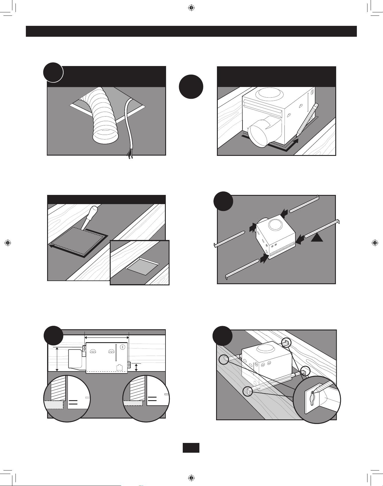
Construcción existente accesible desde arriba
5/8
1/2
C11
Retire el ventilador existente y asegúrese que la abertura sea
suficientemente grande para acomodar el alojamiento del
VENTILADOR EXISTENTE
motor/soplador nuevo (8 pulg. x 8 1/2 pulg.).
SIN VENTILADOR EXISTENTE
O
Utilice el alojamiento del motor/soplador como una plantilla
para marcar la posición.
C12
C13
8”
Recorte una abertura para el alojamiento. Deslice los rieles de montaje en los soportes.
8.5”
C14
5/8
1/2
Ubique la correcta marca de profundidad en el borde inferior de
la viga, según el espesor de su plancha de yeso.
Marque la posición de los tornillos utilizando los agujeros como
una plantilla.
31
43053-02 - 09/14/2011
Page 32
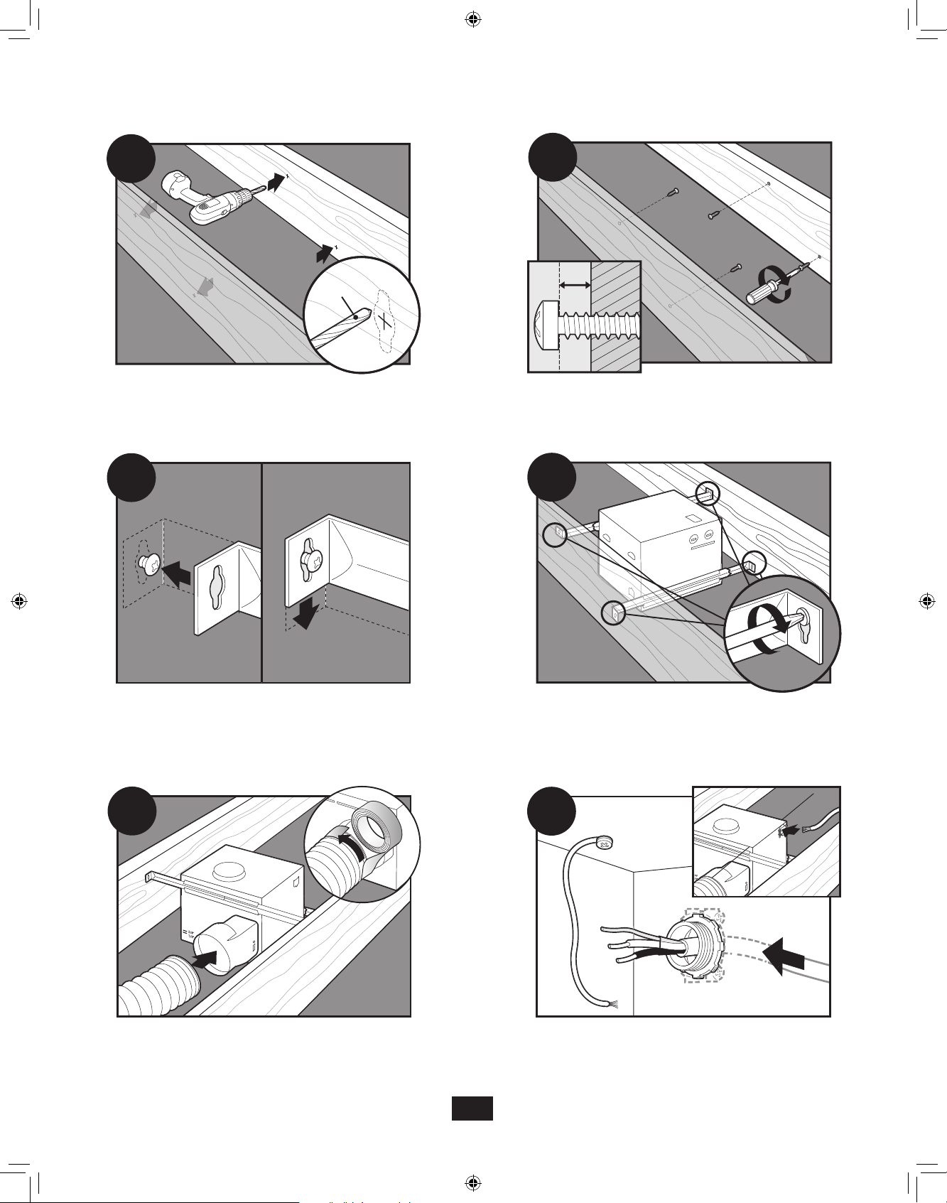
C15
C16
1/8" Bit
C17
Taladre un agujero en el centro de cada perfil.
Fije los rieles con los tornillos.
Introduzca los tornillos, dejando espacio entre la cabeza del
tornillo y la viga. No se proporcionan los tornillos.
C18
Apriete los tornillos.
C19
Conecte un ducto de 4” y ventile hacia el exterior. Aplique cinta
a las uniones. Si el ducto no se ajusta firmemente, puede ser
necesario comprar un adaptador.
C20
Tienda los cables a través del manguito de alivio de tension.
32
43053-02 - 09/14/2011
Page 33

C21
C22
F1
Apriete los tornillos del aliviador de tensiones.
C23
Instale la placa de cubierta del cableado. Asegúrese que todas
las conexiones de cableado estén dentro de la caja o debajo de
la placa de cubierta del cableado.
Vaya al paso F1 en la página 20 para onnectoer les fils tel
qu’indequé comme indiqué.
C24
Conecte el mazo de cables. NO PERMITA QUE EL MOTOR/
SOPLADOR CUELGUE DEL MAZO DE CABLES.
C25
Vuelva a instalar el motor/soplador introduciendo las pestañas
y levantando a su posición. Asegúrese que los alambres no se
pellizquen entre el motor/soplador y el alojamiento.
C26
Asegure el motor/soplador apretando los 2 tornillos.
33
43053-02 - 09/14/2011
Page 34
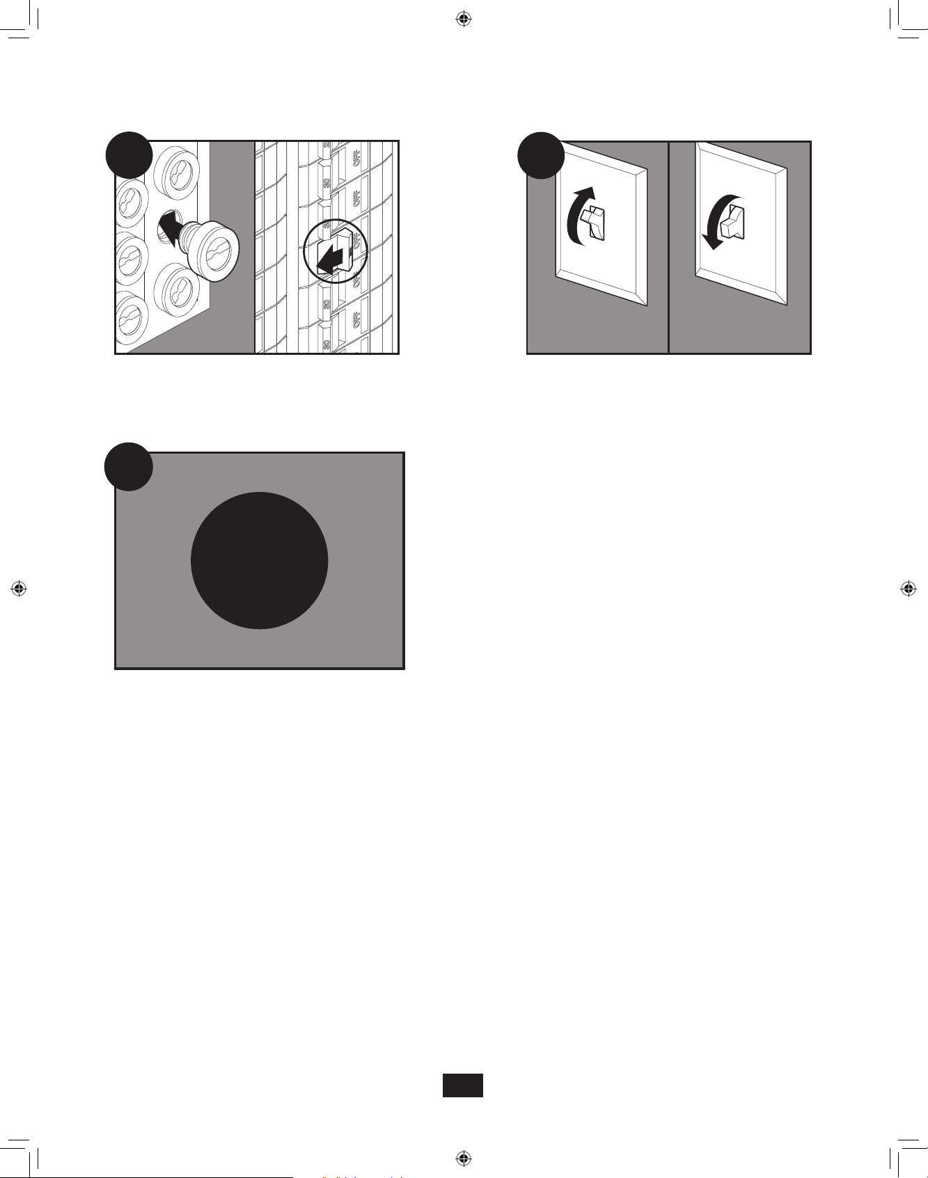
C27
Encendido
Apagado
C28
C28
Encienda la fuente de alimentación.
C29
E1
Vaya al paso E1 en la página 18 para fijar la rejilla.
Pruebe el motor/soplador. Si el motor/soplador no funciona,
verifique la conexión del enchufe.
34
43053-02 - 09/14/2011
Page 35
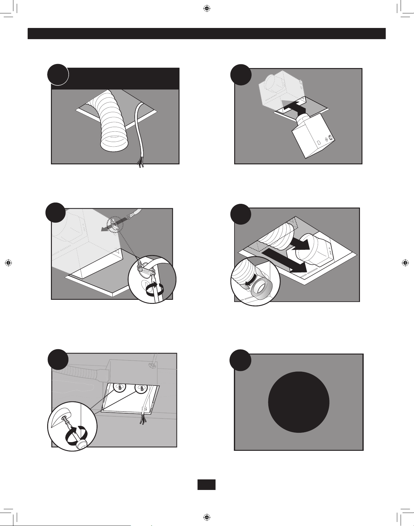
Construcción existente accesible sólo desde abajo
D11
Retire el ventilador existente y asegúrese que la abertura sea
suficientemente grande para acomodar el alojamiento del
motor/soplador nuevo (8 pulg. x 8 1/2 pulg.).
EXISTING FAN
D13
D12
Mueva el alojamiento a su posición encima del techo.
D14
2
Tienda los cables a través del manguito de alivio de tension.
D15
1
Conecte el ducto existente con el conector de ducto. Aplique
cinta a las uniones. Si el ducto no se ajusta firmemente, puede
ser necesario comprar un adaptador.
D16
F1
Instale el alojamiento a nivel con la plancha de yeso y asegúrelo
apretando los tornillos precargados en la viga.
43053-02 - 09/14/2011
Vaya al paso F1 en la página 20 para onnectoer les fils tel
qu’indequé comme indiqué.
35
Page 36

D17
Encendido
Apagado
D18
Instale la placa de cubierta del cableado. Asegúrese que todas
las conexiones de cableado estén dentro de la caja o debajo de
la placa de cubierta del cableado.
D19
Vuelva a instalar el motor/soplador introduciendo las pestañas
y levantando a su posición. Asegúrese que los alambres no se
pellizquen entre el motor/soplador y el alojamiento.
Conecte el mazo de cables. NO PERMITA QUE EL MOTOR/
SOPLADOR CUELGUE DEL MAZO DE CABLES.
D20
Asegure el motor/soplador apretando los 2 tornillos.
D21
Encienda la fuente de alimentación.
D22
36
43053-02 - 09/14/2011
D22
Pruebe el motor/soplador. Si el motor/soplador no funciona,
verifique la conexión del enchufe.
Page 37
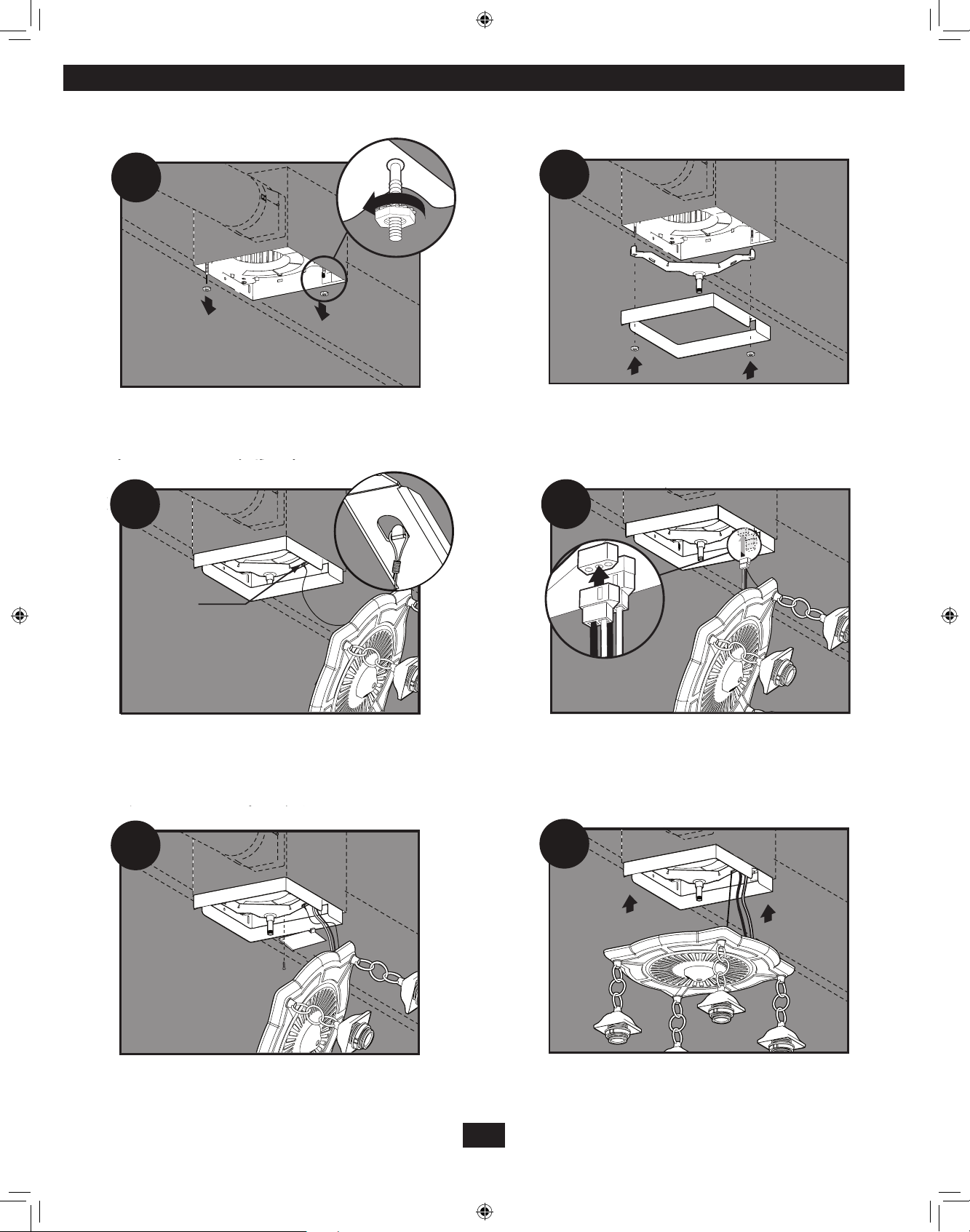
Fijar la rejilla
NOTA: El tamaño, forma y color de los artefactos puede variar.
E1
E3
Retire las dos tuercas de estrella.
E2
Alinee los postes B y D (estampados en el alojamiento del motor) con los
postes B y D (estampados en el artefacto de iluminación). Deslice la barra
de soporte y la placa encubridora hasta los postes.
E4
[a]
Pase el cable de montaje de a través de la placa encubridora,
luego fije el cable de montaje [a] en el soporte de apoyo.
E5
Conecte el manojo de alambres.
E6
Introduzca la pestaña en ángulo del soporte del aliviador de
tensiones para que se enganche en el borde del motor. Reinstale
el tornillo del soporte del aliviador de tensiones.
Levante el bisel hasta la varilla roscada del soporte de apoyo.
37
43053-02 - 09/14/2011
Page 38
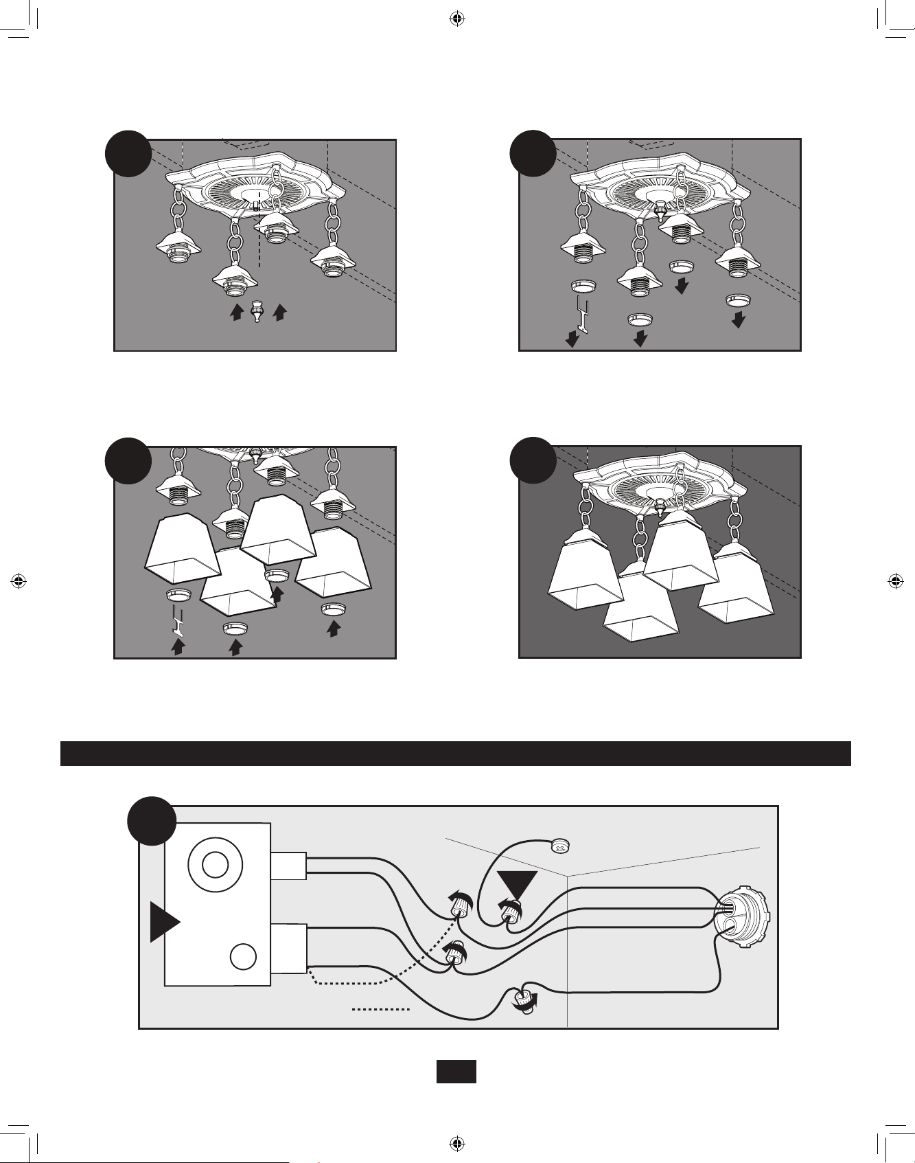
E7
E8
Enrosque la cubierta ornamental en la varilla roscada del
soporte de apoyo.
E9
Coloque la pantalla en los portalámparas y reinstale los anillos
de retención de la pantalla usando la herramienta para el anillo.
Cableado del ventilador
Desenrosque el anillo de retención de la pantalla usando la
herramienta para el anillo suministrada.
E10
Completo.
F2
2
clavijas
Motor del
ventilador
F
3
Luz
*Opción Ventilador y luz principal juntos
clavijas
Negro
Blanco
Blanco
Negro Luz
*Opción
Conecte los alambres como se muestra.
38
43053-02 - 09/14/2011
Tierra
Verde
A
Cobre desnudo
Negro Interruptor principal 1 (CA)
Blanco
Negro Interruptor 2 (CA)
Page 39
Solución de problemas
Problema: El ventilador no está
operando.
Problema: La luz no funciona.
Problema: El ventilador hace ruido.
Solución:
• Los ventiladores de baño Hunter Fan son muy silenciosos. Para conrmar que
el ventilador esté funcionando, coloque su mano cerca de los conductos de
ventilación para sentir el movimiento del aire.
• Encienda la alimentación eléctrica, reemplace el fusible o restablezca el
interruptor automático.
• Verique todas las conexiones de los enchufes para asegurarse que estén
rmes.
• Verique el cableado para asegurarse que coincida con el diagrama de
cableado.
Solución:
• Reemplace la bombilla con una nueva.
• Encienda la alimentación eléctrica, reemplace el fusible o restablezca el
interruptor automático.
• Verique todas las conexiones de los enchufes para asegurarse que estén
rmes.
• Verique el cableado para asegurarse que coincida con el diagrama de
cableado.
Solución:
• Verique y apriete todos los pernos y tornillos.
• Verique la pantalla para asegurarse que esté rme.
• Verique la clapeta para asegurarse que se mueva con libertad.
Si necesita repuestos o servicio, llame al 888-830-1326
39
43053-02 - 09/14/2011
Page 40

Garantía
Hunter Fan
Ventilateur de salle de bain
GARANTIE LIMITÉE
Le fabricant offre la garantie limitée suivante à l’usager initial ou au client acheteur de ce ventilateur de salle de bain:
Si une pièce quelconque de votre ventilateur de salle de bain (à l’exception des pièces en verre et des ampoules) fait défaut durant l’année suivant la
date de l’achat à cause d’un défaut de matériel ou de main-d’œuvre, nous réparerons ou remplacerons, à notre choix, la pièce défectueuse, sans frais
de pièces ou de main-d’œuvre. Après cette période d’un an, vous serez responsable pour tous les frais de pièces et de main-d’œuvre pour les réparations du ventilateur de salle de bain, à l’exception des réparations au moteur telles qu’offertes ci-dessous.
Si votre moteur de ventilateur de salle de bain tombe en panne durant les cinq ans suivant la date de votre achat à cause d’un défaut de matériel ou
de main-d’œuvre, nous vous offrirons sans frais le travail et les matériaux pour réparer ce défaut. Si aucune pièce de rechange ne peut être fournie,
nous rembourserons le prix d’achat réel de votre ventilateur de salle de bain ou nous vous en fournirons un, sans frais, en remplacement, à notre
choix. Après cette période de cinq ans, vous serez responsable pour tous les frais de pièces et de main-d’œuvre pour les réparations du ventilateur
de salle de bain.
SI L’USAGER RÉSIDENTIEL INITIAL OU LE CLIENT ACHETEUR CESSE D’ÊTRE PROPRIÉTAIRE DU VENTILATEUR, CETTE GARANTIE ET
TOUT AUTRE GARANTIE IMPLICITE QUI RESTENT ENCORE VALIDES, INCLUANT, MAIS SANS Y ÊTRE LIMITÉE, TOUTE GARANTIE IMPLICITE DE QUALITÉ MARCHANDE OU DE COMPATIBILITÉ À UN USAGE PARTICULIER, SONT ANNULÉES. AUCUNE GARANTIE EXPRESSE OU
IMPLICITE, INCLUANT TOUTE GARANTIE IMPLICITE DE LA QUALITÉ MARCHANDE OU DE COMPATIBILITÉ À UN USAGE PARTICULIER,
N’EST FAITE À L’ÉGARD DES PIÈCES DE VERRE OU DES AMPOULES OU DU FINI DE TOUTE PARTIE MÉTALLIQUE DU VENTILATEUR.
CETTE GARANTIE TIENT LIEU DE TOUT AUTRE GARANTIE EXPRESSE. LA DURÉE DE TOUTE GARANTIE IMPLICITE, INCLUANT, MAIS SANS
Y ÊTRE LIMITÉE, UNE QUELCONQUE GARANTIE IMPLICITE DE QUALITÉ MARCHANDE OU DE COMPATIBILITÉ À UN USAGE PARTICULIER,
EST EXPRESSÉMENT LIMITÉE À LA PÉRIODE DE LA GARANTIE EXPRESSE ÉNONCÉE PLUS HAUT POUR LES MOTEURS ET AUTRES
PIÈCES.
Cette garantie est nulle si votre ventilateur n’a pas été acheté et installé aux É.-U. ou au Canada. Cette garantie exclue et ne couvre pas les défauts, les mauvais fonctionnements et les pannes d’un ventilateur, dus à des réparations par des personnes auxquelles nous n’avons pas donné
d’autorisation, à l’utilisation de pièces ou d’accessoires non autorisées, à un mauvais traitement, à des modications ou des dommages au ventilateur
tandis qu’il était en votre possession, ou à un usage déraisonnable, y compris l’incapacité de fournir un entretien raisonnable et nécessaire.
Pour bénécier du service, prenez contacter le Département de service clients de Hunter Fan à 1-866-405-3814. Si nous vous autorisons à faire cet
envoi, Vous devrez assumer les frais d’assurance et de transport à notre usine ou à notre centre de service. Nous vous retournerons votre ventilateur de salle de bain Hunter Fan en port prépayé. Votre ventilateur de calle de bain devra être emballé avec soin pour éviter tout dommage durant le
transport puisque nous ne pourrons être tenus responsables d’un tel dommage. Une preuve d’achat est exigée pour obtenir un service de garantie.
L’acheteur devra présenter une facture ou un autre document qui établit la preuve de l’achat.
EN AUCUN CAS, LA SOCIÉTÉ NE SERA TENUE RESPONSABLE DES DOMMAGES ACCESSOIRES OU INDIRECTS.
CERTAINS ÉTATS (OU PROVINCES) N’AUTORISENT PAS DE RESTRICTIONS SUR LA DURÉE DE LA GARANTIE IMPLICITE OU SUR
L’EXCLUSION OU LA RESTRICTION DES DOMMAGES ACCESSOIRES OU INDIRECTS; PAR CONSÉQUENT, LA RESTRICTION OU LES EXCLUSIONS CI-DESSUS POURAIENT NE PAS S’APPLIQUER À VOUS.
CETTE GARANTIE VOUS DONNE DES DROITS LÉGAUX SPÉCIFIQUES ET VOUS POURRIEZ ÉGALEMENT AVOIR D’AUTRES DROITS QUI
PEUVENT VARIER SELON LES ÉTATS ET LES PROVINCES.
Fan Company
7130 Goodlett Farms Pkwy Suite 400Memphis, TN 38016
40
43053-02 - 09/14/2011
© 2011 Hunter Fan Company
 Loading...