

Page 1
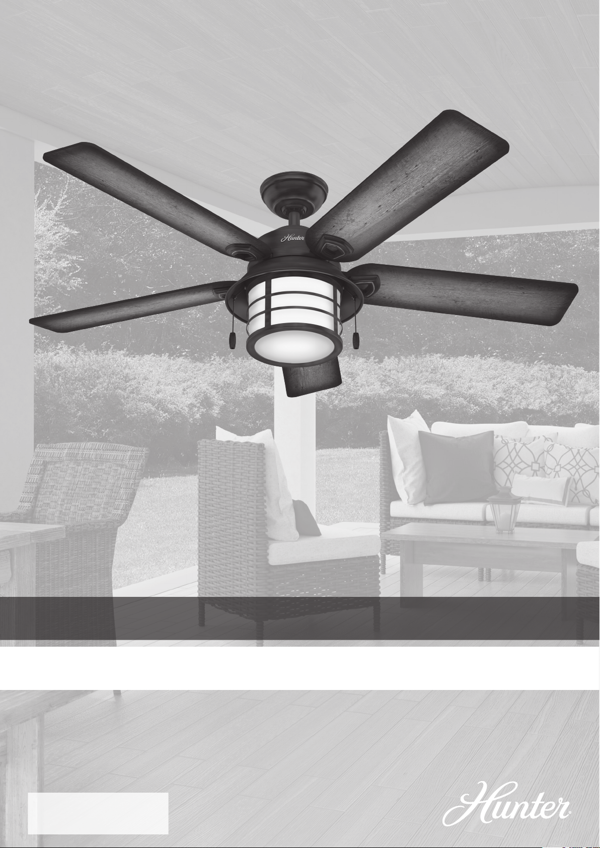
Models: 59135 Weathered Zinc
59273 Onyx Bengal
Weight ±2 lbs: 25.8 lbs (11.7 kg)
Key Biscayne
Installation Manual
©2017 Hunter Fan Co.
M3556-01 r030117
Page 2
1886
1886
The ceiling fan you purchased will provide comfort and performance in your home or ofce for many years. This
Here is what comes in your box:
Congratulations on purchasing your new Hunter® ceiling fan!
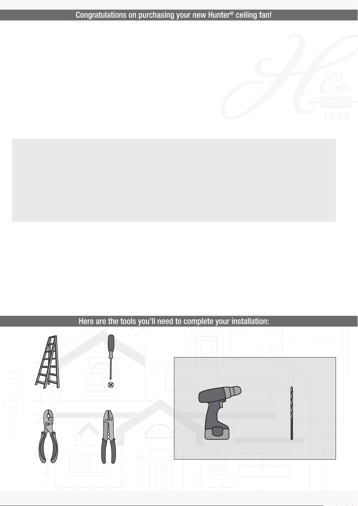
Here are the tools you’ll need to complete your installation:
instruction manual contains complete instructions for installing and operating your fan. We are proud of our work and
appreciate the opportunity to supply you with the best ceiling fan available anywhere in the world.
We are here to help!
This Instruction Manual is designed to make installation as simple as possible. While working through this Instruction
Manual, keep your smartphone or tablet nearby. We have added video links to help you through the more technical
sections. If you are unfamiliar or uncomfortable with wiring, contact a qualied electrician. We also provide telephone
support at 1.888.830.1326 or visit us at HunterFan.com.
Read and Save These Instructions
This product conforms to UL Standard 507.
Warning
w.1 - To reduce the risk of re, electrical shock, or personal injury, mount fan directly from building structure and/or an outlet box marked acceptable for fan support of 70 lbs
(31.8 kg) and use the mounting screws provided with the outlet box.
w.2 - To avoid possible electrical shock, before installing or servicing your fan, disconnect the power by turning off the circuit breakers to the outlet box and associated wall
switch location. If you cannot lock the circuit breakers in the off position, securely fasten a prominent warning device, such as a tag, to the service panel.
w.3 – To reduce the risk of electric shock, this fan must be installed with an isolating wall control/switch.
w.4 - To reduce the risk of personal injury, do not bend the blade brackets when installing the blade brackets, balancing the blades, or cleaning the fan. Do not insert foreign objects in between
rotating fan blades.
Caution
c.1 - All wiring must be in accordance with national and local electrical codes ANSI/NFPA 70. If you are unfamiliar with wiring, use a qualied electrician.
c.2 - Use only Hunter replacement parts.
2
OPTIONAL
If mounting to a support structure, you will also need these tools.
Ladder
Pliers
Screwdriver
Wire Strippers
9/64” Drill BitDrill
Page 3

1886
We recommend that you pull everything out of the box and lay it out. We have
Here is what comes in your box:
grouped the drawn components below with the hardware you’ll need for those
parts. The screws below are drawn to scale to make it easier to identify what
piece of hardware is needed to install each component.
Hunter Pro Tip:
Do not discard the hardware bags or mix parts from
different bags. Make note of the symbol printed on
each hardware bag. The symbols can be used to
identify the appropriate hardware for each step.
bag
Washer
x2
For installing the hanger bracket and wiring the fan
Blade
x5
Blade Medallion
For installing the blades
x5
Blade Arm
x5
Wire Nut
bag
Wood Screw
x4
Blade Screw
bag
x2
x15
x10
Blade Arm Screw
Ceiling Bracket
Canopy
Downrod
bag
For installing the canopy
bag
Canopy Screw
x2
Housing
Screw
x3
bag
For your convenience,
you may receive extra fasteners.
Spare Parts
Light Fixture Hood
x3
Fixture Mounting Screw
bag
Light Fixture
x6
Fixture Screw
Glass
Bulb
x2
Light Fixture Cage
For installing the light xture
Find a part that is missing or damaged?
Don’t take it back to the store. Let us make it right. Visit us at HunterFan.com or call us at 1.888.830.1326.
3
Page 4
1886
Installing the Ceiling Bracket
Installing the Housing
Choosing the Right Installation Location
Checking the Ceiling Angle:
Angled Mounting
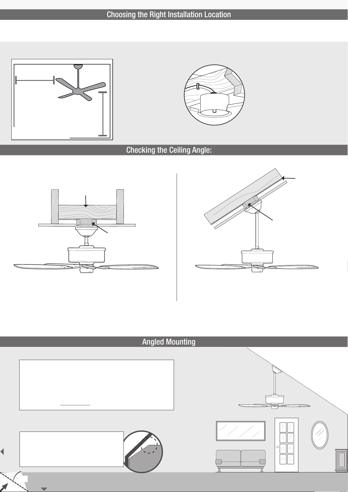
You probably bought this fan with a location in mind. Let’s check below to make sure it is a good t.
Check the room dimensions: Check the outlet box:
30 inches
from blade tip to
nearest wall or
obstruction
7 feet
from bottom edge
of blade to the
oor
Standard Mounting
Support Structure
Outlet Box
(required)
Ceiling
You must be able to
secure the fan to building
structure or fan-rated
outlet box.
Support
Structure
Angled Mounting
Ceiling
Outlet Box
(required)
CEILING
If you have a at ceiling:
Hang your fan by a standard downrod. Some fans come
with a shorter downrod for a Low Prole installation.
A little more information on Angled Mounting:
For optimum performance and appearance, a longer downrod should
be used with your Hunter ceiling fan when installing on high or angled
ceiling. If your ceiling is angled greater than 34° you will also need an
Angled Mounting Kit. Longer downrods and the Angled Mounting Kit are
sold separately at HunterFan.com.
Hunter Pro Tip:
Determining if you need an Angled Mounting Kit:
Fold on the dotted line. Place against edge againts
the wall. Slide towards the ceiling.
If the guide touches the wall but not the ceiling, you
need an angled mounting kit.
If you have an angled or vaulted ceiling:
1. You will need a longer downrod. (sold separately at HunterFan.com)
2. If your ceiling angle is greater than 34°, you will also need an
Angled Mounting Kit. (Sold separately at HunterFan.com)
4
34°
WALL
Page 5
1886
Installing the Ceiling Bracket
Installing the Housing
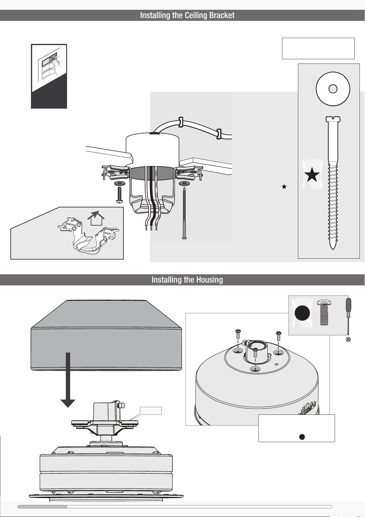
You have two options for installation. Pick which one works best for your location. Remove any existing
bracket prior to installation. Only use the provided Hunter ceiling bracket that came in your fan’s box.
Turn Power
Option 1:
Machine Screws
Use machine screws (provided with outlet box) when
securing to existing ceiling
fan-rated outlet box. Make
sure it is securely installed
and is acceptable for fan
support of 31.8 kg (70 lbs)
or less.
ANG
For angled ceilings,
point opening
toward peak.
OFF
M
D
E
L
Do this rst!
G
N
I
T
N
OU
Hunter Pro Tip:
The machine screws are the ones
that came with your outlet box.
Washer
x2
Option 2:
Wood Screws
Use wood screws (included)
when securing to support
structure with approved
electrical outlet box. Drill
9/64” pilot holes in support
structure to aid in securing
ceiling bracket with
hardware found in the
hardware bag.
P
I
T
bag
x2
Wood Screw
Motor Plate
Housing Screw
bag
Align the screw holes in the top of the
housing with the screw holes in the
motor plate. Install the three housing
screws, found in the hardware bag.
x3
Ceiling Bracket Housing Downrod Hanging Fan Wiring BladesCanopy Light FixtureHood Pull Chains Glass/Cage
5
Page 6
1886
Wiring the Fan
Hanging the Fan
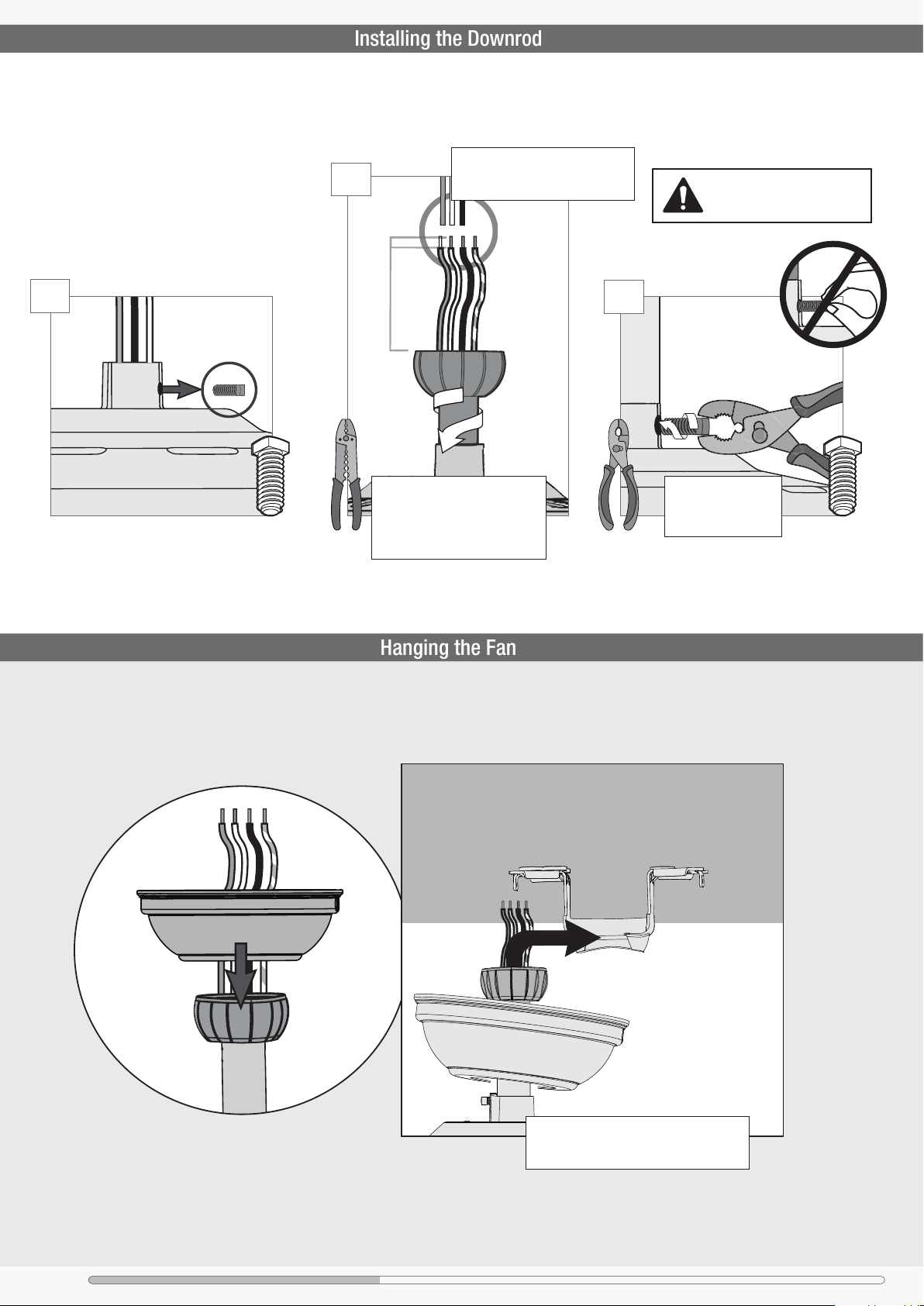
Installing the Downrod
Follow below if you are using the downrod that came pre-assembled in your box. Need to
install a longer or shorter downrod? Check out the guide at the end of this manual.
Hunter Pro Tip:
The ground wire attached to the
2
STEP
3/8”
downrod is approximately 8 inches.
T
U
C
P
I
R
T
S
&
If the setscrew is not tightened
securely, the fan may fall.
1
STEP
8”
(not to scale)
E
E
P
K
!
Hand tighten the downrod (at least
4-5 full turns) until it stops. Trim
the wires coming from the fan so
that 8-inches remain coming from
the top of the downrod.
3
STEP
Tighten the setscrew
with pliers. DO NOT
HAND TIGHTEN.
6
S
l
i
d
e
c
a
n
o
p
y
o
v
e
r
d
o
w
n
r
o
d
a
n
d
w
i
r
e
s
.
Ceiling Bracket Housing Downrod Hanging Fan Wiring BladesCanopy Light FixtureHood Pull Chains Glass/Cage
DO NOT PICK THE FAN UP BY THE CANOPY
OR WIRES. Place the downrod ball into the
slot in the ceiling bracket.
Page 7
1886
We know wiring is hard. Let’s make it easier.
Wiring the Fan
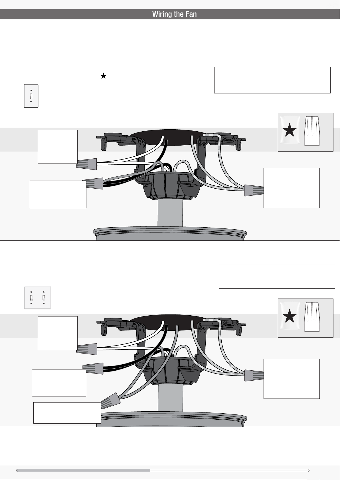
Follow these steps to get your fan wired quickly and safely. Follow the route below that best matches your wall switch
setup. If you are unfamiliar with wiring or uncomfortable doing it yourself, please contact a qualied electrician.
You are going to need these:
4 Wire Nuts (these are in the bag)
Have a single switch?
Follow these steps:
Connect the white
(grounded) wire
from the ceiling
to the white wire
from the fan.
Connect the black wire
(ungrounded) from the
ceiling to the black and the
blue wires from the fan.
Grounded
White
Black
Blue
Hunter Pro Tip:
Here is how to connect the wires:
Push the bare metal ends of the wires together and slide a wire
nut over them. Then, twist the wire nut clockwise until tight.
Give it a gentle pull to make sure none of the wires are loose.
G
r
e
e
n
/
Y
e
l
Grounding
Green/Yellow Stripe
l
o
w
S
t
r
i
p
e
Connect the three
grounding wires (green,
green/yellow stripe, or
bare copper) coming from
the ceiling, downrod, and
hanging bracket.
bag
x4
Wire Nut
Have dual switches?
Follow these steps:
Connect the white
(grounded) wire
from the ceiling
to the white wire
from the fan.
Connect the black
(ungrounded) wire from
the ceiling to the black
wire from the fan.
Connect the second ungrounded
(light) wire from the ceiling to
the blue wire from the fan.
White
Ungrounded
Black
Grounded
Blue
Ungrounded (light)
Hunter Pro Tip:
Have extra wiring?
Turn the wires upward and push them carefully back through
the hanger bracket into the outlet box. Make sure that the
wires are still attached to the wire nuts.
G
r
e
e
n
/
Y
e
l
Grounding
Green/Yellow Stripe
l
o
w
S
t
r
i
p
e
Connect the three
grounding wires (green,
green/yellow stripe, or
bare copper) coming from
the ceiling, downrod, and
hanging bracket.
bag
x4
Wire Nut
Ceiling Bracket Housing Downrod Hanging Fan Wiring BladesCanopy Light FixtureHood Pull Chains Glass/Cage
7
Page 8
1886
Installing the Canopy
Installing the Blades:
Preparing the Light Fixture
Installing the Light Fixture Hood
F
i
t
t
h
e
c
a
n
o
p
y
i
n
p
l
a
c
e
a
s
s
h
.
o
n
w
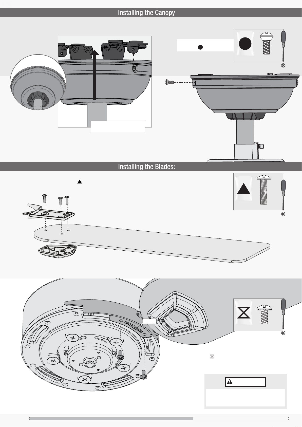
Place each blade between a blade arm and blade medallion.
Install three blade screws, found in the hardware bag, to
attach the blade medallion to the blade arm.
Lift the canopy into place so that
the screw holes are aligned.
Insert the two canopy screws
found in the hardware bag.
bag
x2
Canopy Screw
Repeat x5
Ridge
bag
bag
x15
Blade Screw
x10
Blade Arm Screw
8
Lightly attach the blade arms to the motor with
screws found in the hardware bag, then
securely tighten after both screws are attached.
Repeat x5
IMPORTANT
NOTE: The blade arms should be mounted with
the ridge facing downward. Installing it incorrectly
could result in your fan not functioning.
Ceiling Bracket Housing Downrod Hanging Fan Wiring BladesCanopy Light FixtureHood Pull Chains Glass/Cage
Page 9
1886
Preparing the Light Fixture
Installing the Light Fixture Hood
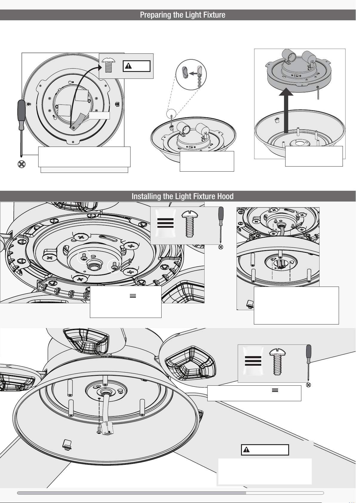
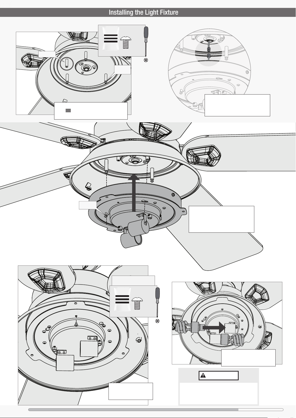
Follow these steps to prepare the light xture for installation.
x1
Fixture Screw
Red Flag
Remove the pre-installed xture screw and red
ag from the light kit assembly. Save the screw.
It will be needed for light kit installation.
Note: The screw was installed for shipping purposes only.
KEEP
Fixture Mounting Screw
bag
Repeat x2
Remove and discard the
plastic connectors from the
ends of the two pull chains.
2 of 3
Carefully remove the light
xture from the light xture
hood and set the light xture.
Partially install two xture mounting
screws ,found in the hardware
bag, into the motor housing as
shown. It does not matter which two
screw holes you choose.
Feed the wire plug through the center hole of
the light xture hood. Align the keyhole slots
in the hood with the two screws you just
installed. Lift the hood so that the keyhole
slots engage the two screws, and twist
counterclockwise to lock the hood into place.
3 of 3
Fixture Mounting Screw
bag
Insert the third screw, found in the hardware
bag, into place and then tighten all three screws.
IMPORTANT
Make sure the upper switch housing is securely
attached to the mounting plate. Failure to properly
secure all 3 assembly screws could result in the
switch housing xture falling.
Ceiling Bracket Housing Downrod Hanging Fan Wiring BladesCanopy Light FixtureHood Pull Chains Glass/Cage
9
Page 10
1886
Installing the Pull Chains
Installing the Glass and Light Fixture Cage
Installing the Light Fixture
Empty Post
bag
Partially install three xture screws, found
in the hardware bag, into the posts as
shown, leaving the circled post empty.
3 of 4
Fixture Screw
Fixture
Screw
Connect the plugs from the upper and
lower switch housings. Make sure to
line up the colored markings on the
connectors and that the connectors latch.
Keyhole
Slot
This is the screw you saved that
was attached to the red ag.
4 of 4
Fixture Screw
bag
Align the three keyhole slots in the light
kit with the three assembly screws in
the posts. Lift the light kit and twist
clockwise to lock it into place. Be sure
that both pull chains are hanging freely.
10
Install a bulb into each of the
sockets. When necessary, replace
with bulbs of the same wattage.
IMPORTANT
Install the fourth xture
screw and tighten all four
screws securely.
Ceiling Bracket Housing Downrod Hanging Fan Wiring BladesCanopy Light FixtureHood Pull Chains Glass/Cage
Make sure the lower switch housing is securely
attached to the upper switch housing. Failure to
properly secure all three assembly screws could
result in the light xture falling.
Page 11
1886
Installing the Pull Chains
Installing the Glass and Light Fixture Cage
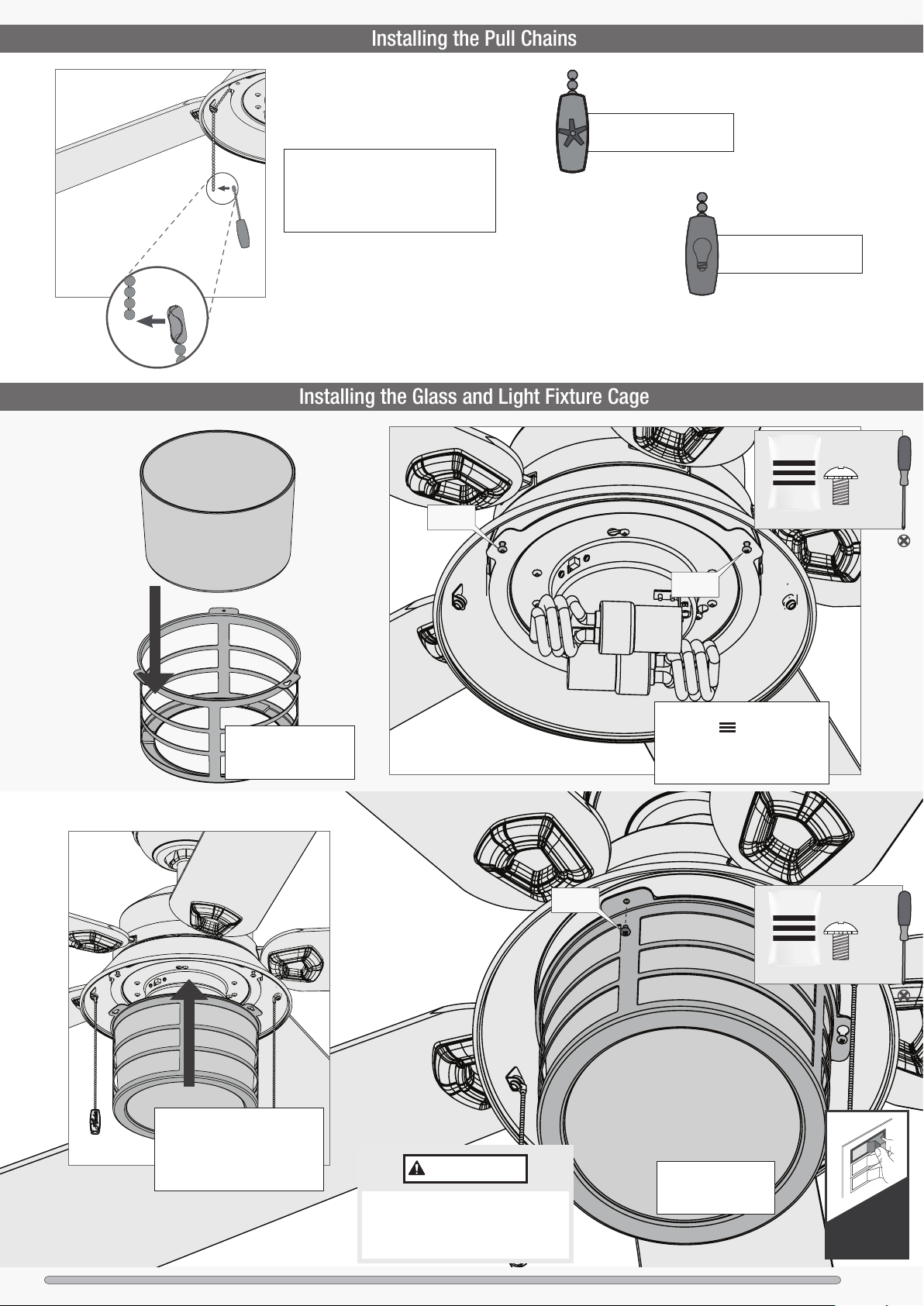
Feed the pull chains from the fan switch
and the light switch down through the
holes in the upper switch housing as
shown. Attach the pull chain pendants to
the light and fan pull chains.
Repeat x2
The fan pull chain controls
the speed: from high to off.
The light pull chain controls
the light xture: on and off.
Carefully lower the glass
into the light xture cage
until it rests in place.
Fixture
Screws
Fixture
Screws
bag
Fixture
Screws
Partially install two xture screws,
found in the hardware bag,
halfway into the light xture as
shown. It does not matter which
two screw holes you choose.
2 of 3
Fixture Screw
Fixture Screw
bag
Align the keyhole slots in the
cage with the partially installed
screws in the light xture. Lift the
cage and twist counterclockwise
to lock it into place.
Make sure the globe assembly is securely
attached to the switch housing. Failure to
properly secure all three assembly screws
could result in the light xture falling.
Ceiling Bracket Housing Downrod Hanging Fan Wiring BladesCanopy Light FixtureHood Pull Chains Glass/Cage
IMPORTANT
Install the third xture
screw and tighten all
three screws securely.
3 of 3
Turn Power
ON
11
Page 12
1886
Reversing the Fan
Troubleshooting
Fan Doesn’t Work
Excessive Wobbling
Noisy Operation
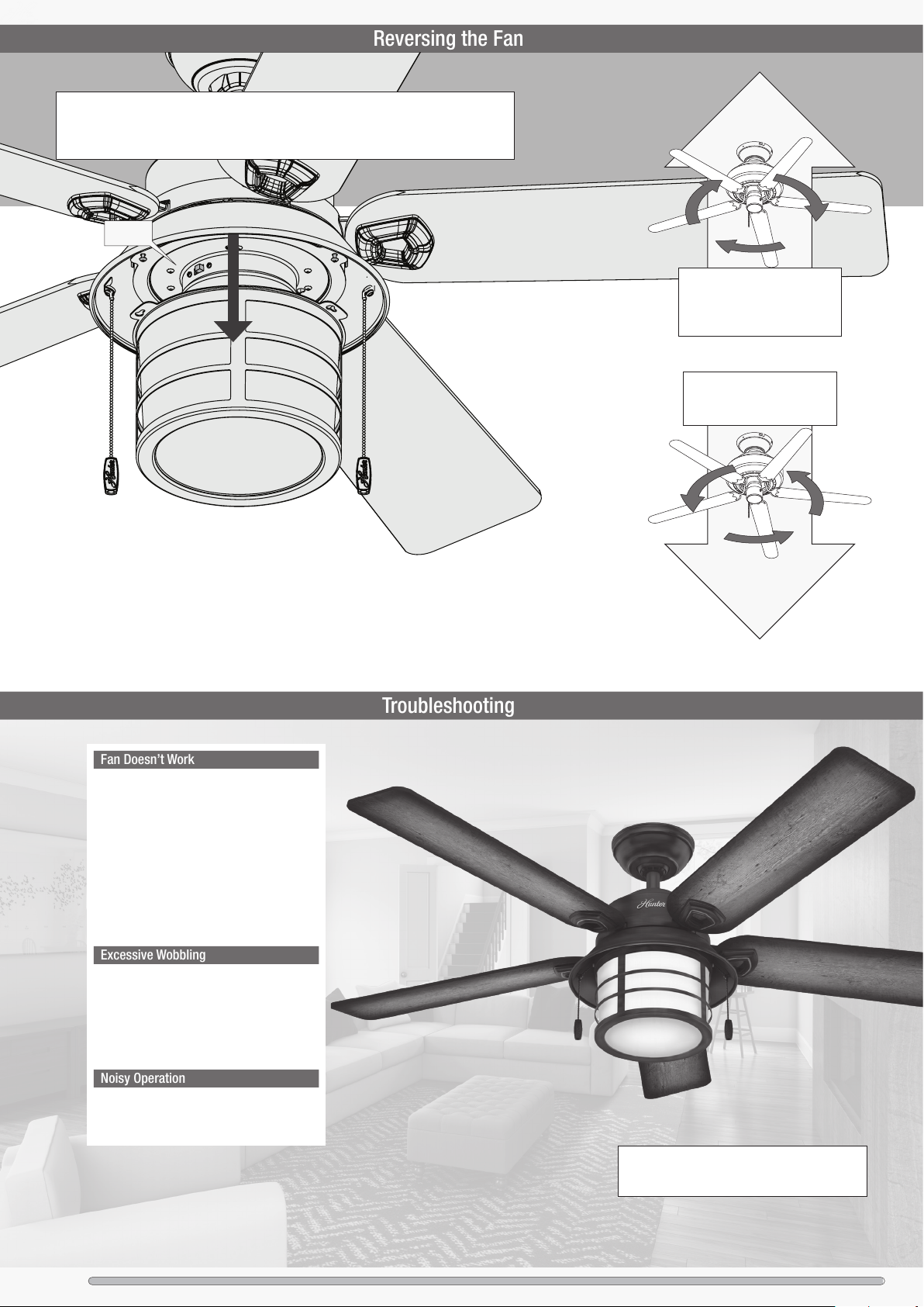
Ceiling fans work in two directions: downdraft (counterclockwise rotation) and updraft (clockwise
rotation). To change the direction of air ow, turn the fan off and let it come to a complete stop.
The reversing switch is located inside the light xture cage. It can only be accessed when the
cage is removed. Slide the reversing switch to the opposite position. Restart the fan.
Reverse
Switch
Updraft (counterclockwise
rotation) creates a more indirect
airow. Updraft airow is great
for moving warm air downward.
Downdraft (clockwise rotation)
creates a direct breeze and
maximum cooling effect.
• Make sure power switch is on.
• Push the motor reversing switch rmly left or right
to ensure that it is engaged.
• Check the circuit breaker to ensure the power is
turned on.
• Make sure the blades spin freely.
• Turn off power from the circuit breaker, then loosen
the canopy and check all the connections according
to the wiring diagram.
• Check the plug connection in the switch housing.
• Make sure the blades are properly installed on the
blade iron posts.
• Turn the power off, support the fan carefully, and
check that the hanger ball is properly seated.
• Use the provided balancing kit and instructions to
balance the fan.
• Make sure the blades are properly installed.
• Check to see if any of the blades are cracked. If so,
replace all of the blades.
Hunter Pro Tip:
Cleaning the Fan
Use soft brushes or cloths to prevent scratching.
Cleaning products may damage the nishes.
12
Ceiling Bracket Housing Downrod Hanging Fan Wiring BladesCanopy Light FixtureHood Pull Chains Glass/Cage
Page 13
1886
Hunter Fan Company grants this limited warranty to the original purchaser of this Hunter
Limited Lifetime Warranty
Downrod
ceiling fan. This document can be found at www.HunterFan.com.
Thank you for choosing Hunter!
How Can Warranty Service Be Obtained?
Proof of purchase is required when requesting warranty service. The original
purchaser must present a sales receipt or other document that establishes proof of
purchase. Hunter, at its sole discretion, may accept a gift receipt. To obtain service,
contact Hunter Fan Company online or by phone.
www.HunterFan.com/Support/Contact-Us/
1-888-830-1326
Please do not ship your fan or any fan parts to Hunter. Delivery will be refused.
What Does This Warranty Cover?
Motor — Limited Lifetime Warranty
If any part of your ceiling fan motor fails during your ownership of the fan due to a
defect in material or workmanship, as determined solely by Hunter, Hunter will provide
you with a replacement fan free of charge.* The foregoing limited warranty applies only
to the motor itself and does not apply to electronic controls – such as remote control
transmitters, remote control receivers, or capacitors – used in conjunction with the
motor. Such electronic control items are included in the one-year limited warranty below.
Other — One-Year Limited Warranty
Except as otherwise indicated throughout this warranty, if any part of your Hunter ceiling
fan fails at any time within one year of the date of purchase due to a defect in material
or workmanship, as determined solely by Hunter, Hunter will provide a replacement part
free of charge.*
Light Kits — Warranty May Vary
Light kits are included in the one-year limited warranty. However, you may qualify for
additional warranty coverage if your fan includes one of the following:
• LED Light Kits — Three-Year Limited Warranty
If your LED light kit module (not including glass components) or LED bulb
fails at any time within three years of the date of purchase due to a defect
in material or workmanship, as determined solely by Hunter, Hunter will
provide a replacement part free of charge.*
• ENERGY STAR® Rated Light Kits — Three-Year Limited Warranty
If your ENERGY STAR rated light kit (not including glass components) fails
at any time within three years of the date of purchase due to a defect in
material or workmanship, as determined solely by Hunter, Hunter will provide
a replacement light kit free of charge.*
* If no replacement product/part can be provided for your fan, we will provide a comparable or
superior replacement product/part at the sole discretion of Hunter.
What Does This Warranty NOT Cover?
Labor Excluded. This warranty does not cover any costs or fees associated with the labor
(including electrician’s fees) required to install, remove, or replace a fan or any fan parts.
There is no warranty for light bulbs (except where otherwise noted); remote control
batteries; fans purchased or installed outside the United States; fans owned by
someone other than the original purchaser; fans for which proof of purchase has not
been established; fans purchased from an unauthorized dealer; ordinary wear and tear;
minor cosmetic blemishes; refurbished fans; and fans that are damaged due to any
of the following: improper installation, misuse, abuse, improper care, failure to follow
Hunter instructions, accidental damage caused by the fan owner or related parties,
modications to the fan, improper or incorrectly performed maintenance or repair,
improper voltage supply or power surge, use of improper parts or accessories, failure to
provide maintenance to the fan, or acts of God (e.g. ood).
ORIGINAL PURCHASER’S SOLE AND EXCLUSIVE REMEDY FOR A CLAIM OF ANY KIND
WITH RESPECT TO THIS PRODUCT SHALL BE THE REMEDIES SET FORTH HEREIN.
HUNTER FAN COMPANY IS NOT RESPONSIBLE FOR CONSEQUENTIAL OR INCIDENTAL
DAMAGES, DUE TO PRODUCT FAILURE, WHETHER ARISING OUT OF BREACH OF
WARRANTY, BREACH OF CONTRACT, OR OTHERWISE. Some States do not allow the
exclusion or limitation of incidental or consequential damages, so the above limitation or
exclusion may not apply to you.
ANY IMPLIED WARRANTIES OF MERCHANTABILITY OR FITNESS FOR A PARTICULAR
PURPOSE APPLICABLE TO THIS PRODUCT ARE LIMITED IN DURATION TO THE PERIOD OF
COVERAGE OF THE APPLICABLE LIMITED WARRANTIES SET FORTH ABOVE. Some States
do not allow limitations on how long an implied warranty lasts, so the above limitation
may not apply to you.
How Does State Law Affect Warranty Coverage?
This warranty gives you specic legal rights. You may also have other rights which vary
from state to state.
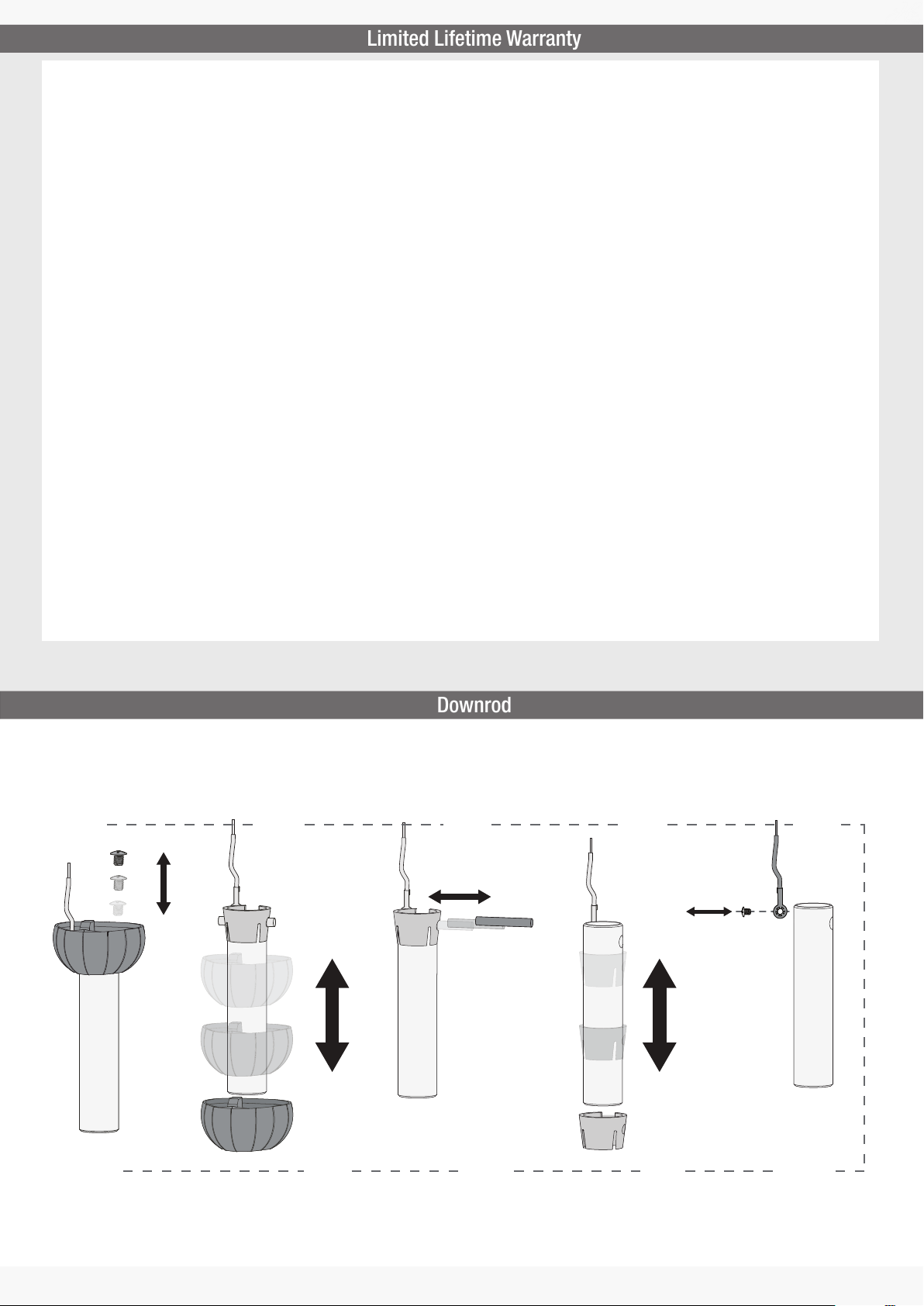
If you need a different downrod length follow these steps:
Follow steps 1-5 to remove standard downrod pipe
1 2 3 4 5
Follow steps 6-10 to reassemble with new downrod
678910
13
 Loading...