

Page 1
Page 2

Before attempting to install or operate your Humminbird LCR it is recommended that you read the
operations manual thoroughly. The LCR has a number of special features not found on any other
depth sounder. Therefore, to completely understand all the features we suggest you follow the
instructions in this manual. If, after reading the instructions, there is something you do not
completely understand about the operation of your unit, we recommend you contact our
Customer Service Department -CALL
334-687-0503
Our Customer Service hours are Monday - Friday 8:00 A. M.-5:00 P. M.
Please complete your warranty card and return it to us immediately.
Thank you.
INTRODUCTION
Congratulations on selecting the LCR4x6. Your new Humminbird LCR incorporates the most
advanced, innovative concepts in sonar equipment. The LCR is probably the most intelligent
depth sounder ever created. Advanced microcomputer technology is used to simplify its
operation, not complicate it, so you can quickly learn the basics of operating your unit. You will
find even the advanced features, such as Split Screen Zoom and Screen Memory, are easy to
learn and fun to use.
Your Humminbird LCR has a number of outstanding features including a unique automatic
feature. This computer-controlled feature, pioneered by Humminbird, makes using your LCR as
simple as pushing the “Power” button. The computer will automatically adjust the sensitivity,
change the depth scale even if the bottom goes off the screen and black out everything below the
bottom to make the display easy to read.
The LCR4x6 control panel is another Humminbird innovation. You have complete control of all
the unit’s features with just seven buttons and an easy-to-understand display of all adjustments is
right on the screen. You will quickly see that the advanced technology of the LCR4x6 is easy to
use and understand.
Other features include Split Screen Zoom and Bottom Lock, Screen Memory, Total Screen
Update, large digital bottom depth readout, Fish Alarm, Bottom Alarm, and optional Surface
Temperature and Speed Gauges for readings on the LCR screen.
The LCR has a large 6-inch by 4-inch visibility LCD, a night -light, waterproof enclosure, and a
low profile swivel mount. Read this operations manual thoroughly to get the most from all the
LCR’s features. You’ll have fun learning to use your LCR4x6 and it will give you many hours of
fishing and boating pleasure.
THEORY OF OPERATION
You Humminbird LCR works on the basic principle of sonar. An electronic signal is generated
within the control head of the unit. When coupled to the transducer, this signal is converted to an
ultrasonic signal and is transmitted toward the bottom. The speed of the ultrasonic signal
travelling through the water is approximately 4800 feet per second.
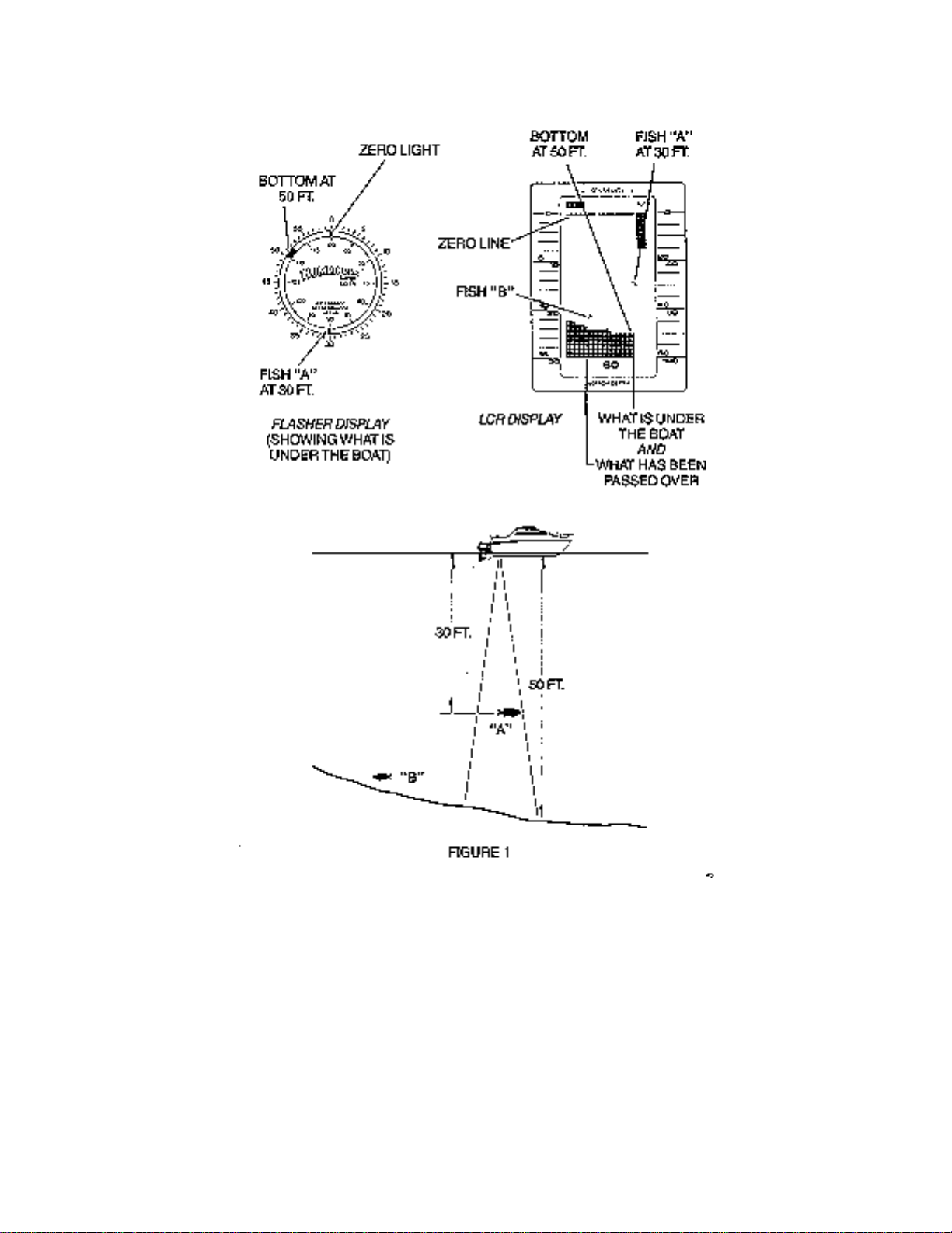
The signal travels through the water until it strikes an object or the bottom. At this instant it is
reflected back, picked up by the transducer, reconverted to an electric signal and is recorded on
the display of the LCR.
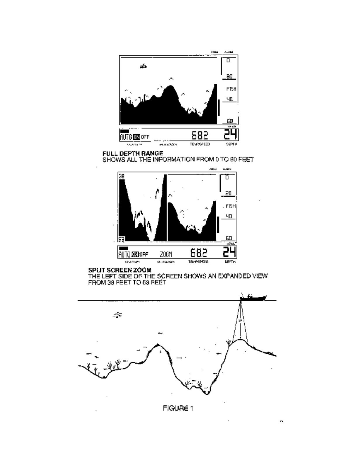
The reading at the far right position of the screed shows what is being passed over at that time.
As new information is received, the old information is shifted to the left and the new information is
added. The information is retained until it disappears from the left side of the screen. Figure 1
illustrates a typical display.
One of the unique features of your LCR is the Split Screen Zoom with Total Screen Update.
Figure 1 shows a Split Screen Zo om display with the full depth range information on the right and
Page 3

the expanded view on the left. The Total Screen Update feature is explained in detail later, but
basically with the Zoom the Total Screen Update allows you to zoom in on an area even after you
have passed by it. The display resolution on the expanded portion of the screen is as good as ¾
inch per dot, giving you exact detail while still viewing the full depth range information on the right.
The display technology used on the LCR4x6 has been pioneered by Humminbird. The display
uses Advanced Super Twist Liquid Crystal Technology for the best contrast, widest viewing angle
and extreme high and low temperature operation.
The Super Twist Liquid Crystal material in the display is a liquid that can be aligned such that it
either “blocks” light or it lets light pass through. The “blocking” of light is what makes the black
dots on the screen.
Since the LCR’s display depends on light passing through it to make the images, increasing the
light source will make it easier to see. This is why your LCR can be seen so well in direct sunlight.
You will also notice that the display can be seen better at certain angles. The LCR mounting has
been designed for tilting and pivoting so that you can easily maint ain a good angle for viewing.
Another characteristic of an LCR display is that you may find that some polarized glasses might
affect the view by causing a rainbow prism to appear. This condition can possibly be improved by
a slight adjustment in tilt.
SPLIT SCREEN OPERATION
The LCR4x6’s split screen feature will allow you to make side-by-side comparisons. You will be
able to split the screen and compare actual, full depth scale information with three functions -1.)
Zoom, 2.) Bottom Lock, or 3.) Screen Memory.
Page 4
Page 5
The use of the split screen is very easy. Whenever any of three functions, Zoom, Bottom Lock,
or Screen Memory, is turned on the screen automatically splits.
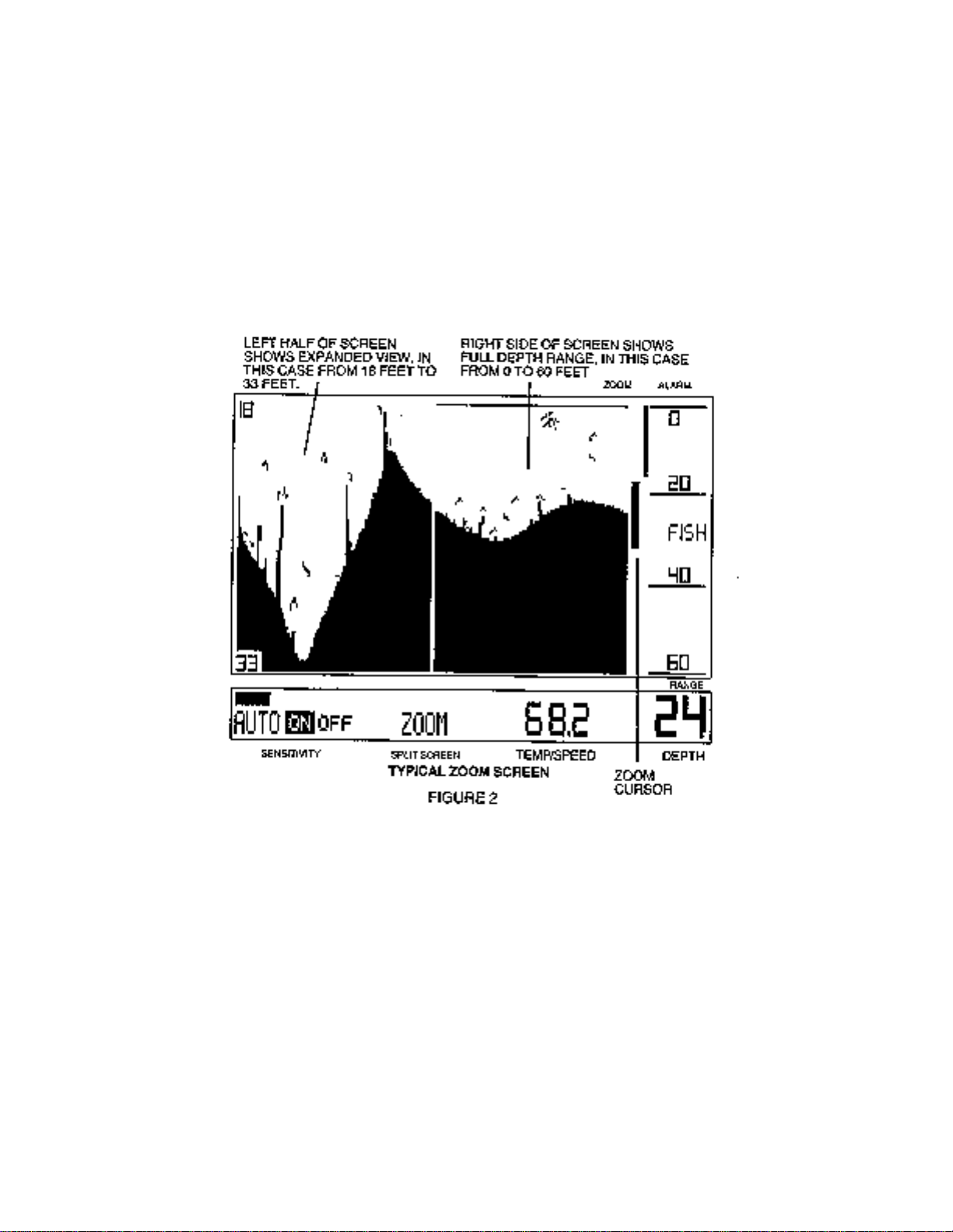
LEFT HALF OF SCREEN RIGHT SIDE OF SCREEN
SHOWS
SHOWS EXPANDED VIEW, IN FULL DEPTH RANGE, IN THIS
CASE
THIS CASE FROM 18 FEET TO FROM 0 TO 60 FEET
33 FEET
When Zoom is activated, for example as shown in figure 2, the left half of the screen any shows
the expanded information while the right half shows the full depth scale information. The Zoom
range can be moved up or down to search out any area. Even the depths of the upper and lower
part of the Zoom region are digitally displayed for precise location of fish and structure.
The bottom lock and screen memory work in the same way to give you the benefit of split screen
comparisons. The detailed operation of each of these functions is explained later in this manual.
TOTAL SCREEN UPDATE
Total Screen Update was invented by Humminbird engineers. You will find this unique feature
very useful and beneficial. It will allow you, when changing depth scales, for example, to totally
change the entire screen to the new depth scale. It will also allow you to ZOOM in and look at
information in much finer detail even after you have already gone over the area.
Page 6

HOW DOES TOTAL SCREEN UPDATE WORK?
Memory devices inside the LCR4x6 can store hundreds of thousands of bits of information
Automatically, while you are operating the unit, the computer is putting information into the LCR’s
memory.
All this information is being put into memory in much smaller increments (pieces) than is being
displayed on the normal full depth scale. For example, on the 0 to 30 foot range-each dot is
equal to 3 inches, or on the 0 to 60 foot range each dot is 6 inches, and so forth. But in the
LCR4x6’s memory information is being stored such that when you Zoom in on a 71/2 foot
increment each dot represents an incredible ¾ inch per dot.
HOW TO USE TOTAL SCREEN UPDATE
It is very easy to use Total Screen Update because the LCR’s computer will do everything
automatically. You will notice how Total Screen Update works when a depth range changes.
When the bottom display goes off the screen, The LCR4x6 will automatically change to the next
deepest range and update the entire screen to the next deepest range and update the entire
screen to the new depth range. This Total Screen Update feature also works when changing to
shallower scales. For example, suppose you are in the 0 to 120 foot scale but the bottom depth
changes quickly to 20 feet. When the depth range is changed to the 0-30 foot scale , the entire
screen will look just as if you had gone over the area on the 0-30 foot scale.
Another way that you will use Total Screen Update is in operating the LCR’s Zoom or Bottom
Lock. Since the computer has stored in memory information in very small increments, you will be
able to recall this information from memory to get an expanded view of areas which you have
already passed over.
For example, if you go over some interesting structure or fish, you will be able to Zoom in for a
closer look without going back over the area by simply activating the Zoom. The information that
is stored in memory will automatically be recalled and displayed on he left side of the screen. The
operation of Zoom is explained in a later section.
The high visibility readout of the LCR allows you to see fish, bottom contour and underwater
structure.
The LCR is designed to operate with a standard 16 degree transducer included with the unit.
Other transducers, such as 32 degrees, cannot be used. In order for your LCR to operate well at
high speeds, you must have a properly mounted transducer. Please read the transducer
mounting procedure carefully.
TRANSDUCER MOUNTING PROCEDURE
Humminbird’s high speed transducer is supplied with your LCR. This transducer has been
designed to give good high speed readings on most all boat designs, including aluminum.
Please carefully consider the following before installing your transducer.
Page 7
TRANSDUCER MOUNTING OPTIONS
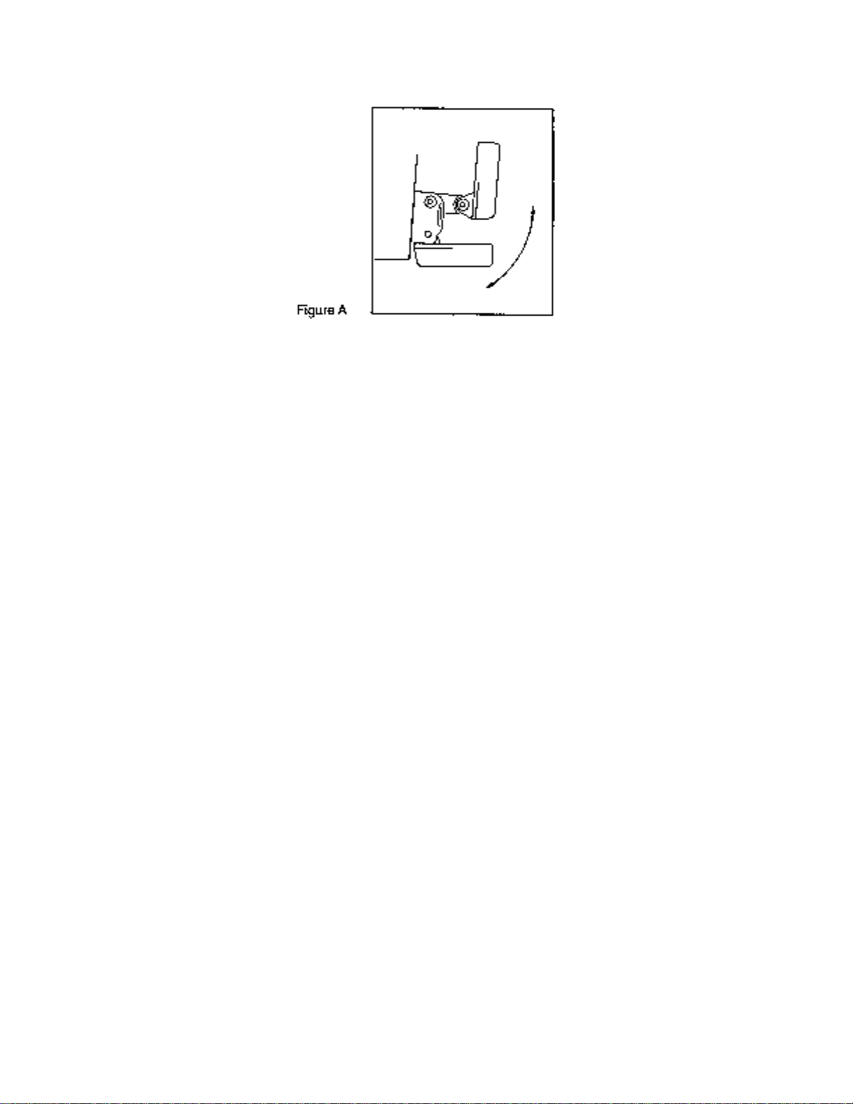
A. Transom Mount - The Humminbird high speed transducer allows the transducer element to be
mounted below the bottom of the boat hull keeping the transducer out of turbulent water and
insuring good high speed operation. The transducer will absorb the blow of any obstruction
by rotating up out of the metal spring bracket without harming the transducer, or your boat.
The transducer can be re-engaged by simply rotating the transducer down and snapping it
back in place. (See Figure A)
Page 8
B. Inside Hull Mount - The high speed transducer can be mounted inside the hull (without pivot
assembly) using the proper two-part epoxy, such as Humminbird’s epoxy kit. Even though
there is some loss of signal in shooting through the hull, your LCR will perform well with this
type of installation. You cannot shoot through the hull of an aluminum boat.
C. Trolling motor Mount - This type of transducer is not supplied with your LCR. It is designed to
mount on the foot of a trolling motor. You may exchange your un-used high speed
transducer for a trolling motor transducer. Call the Humminbird Customer Service
Department.
D. Bronz Thru-Hull Mount - This transducer is not supplied with your LCR but for an additional
cost you may exchange your un-used high speed transducer for a bronz thru-hull. The bronz
thru-hull transducer has a threaded stem which installs through a hole drilled in the boat hull,
leaving the housing exposed under the boat. This type of installation must be used for many
boats with in-board engines, because there is no suitable location on the transom away from
the noise and turbulence created by the prop. A bronz thru-hull transducer should be installed
by qualified personnel only.
The LCR will operate well at high speeds with a properly mounted transducer. Remember, a
transducer will not work transmitting through air or through air bubbles.
1. TRANSOM MOUNTING PROCEEDURE
Step 1.
MOUNTING LOCATION- It is important that the transducer be mounted on the transom where
water flow is in constant contact with the transducer. You may wish to observe the rear of the
boat while it is moving through the water to determine the best mounting location.
Step 2.
BRACKET INSTALLATION (Aluminum Boats)- To install the metal bracket on an aluminum boat
locate the template on the transom between rows of rivets, or ribs that are on the bottom of the
boat. Align the template so that the bottom corner of the template nearest the center of the
transom is on the bottom edge of the transom.
Page 9
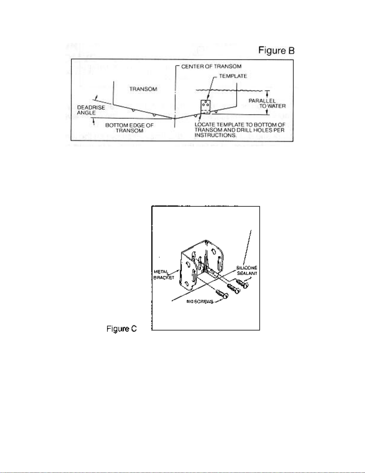
Once the location is determined mark and drill three 7/64” dia.. holes noted on the template.
Attach the metal bracket using three #10 self threading screws supplied. Be sure to align holes in
the center of the
Bracket slots. On some aluminum boats it may be necessary to use a wood back-up plate. It is
important to use a silicone sealant between the screwhead and bracket in order to preve nt
leaking. (See Figure C)
Step 2.
BRACKET INSTALLATION (Fiberglass Boats)- If your boat has a stepped transom located
below and under the main transom, the compact transducer design allows mounting in this area.
This mounting location is recommended for good reading at very high speeds. (See Figure D)
To install the metal bracket on a fiberglass boat, locate the template on the transom in the same
manner as for an aluminum boat. (See Figure C)
Page 10
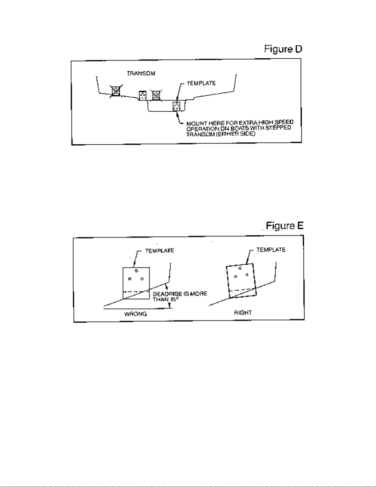
NOTE: On boats with more than 15 degree deadrise angle it may be necessary to mount the
transducer slightly off parallel with the water level. (See Figure E)
Mark and drill the three 9/64” dia. holes as shown on the template. Attach the metal bracket using
the three #10 self threading screws supplied. Be sure to align the holes so that they are centered
vertically in the three slots found in the bracket. It is important to use a silicone sealant between
the screwhead and bracket in order to prevent leaking.
Step 3.
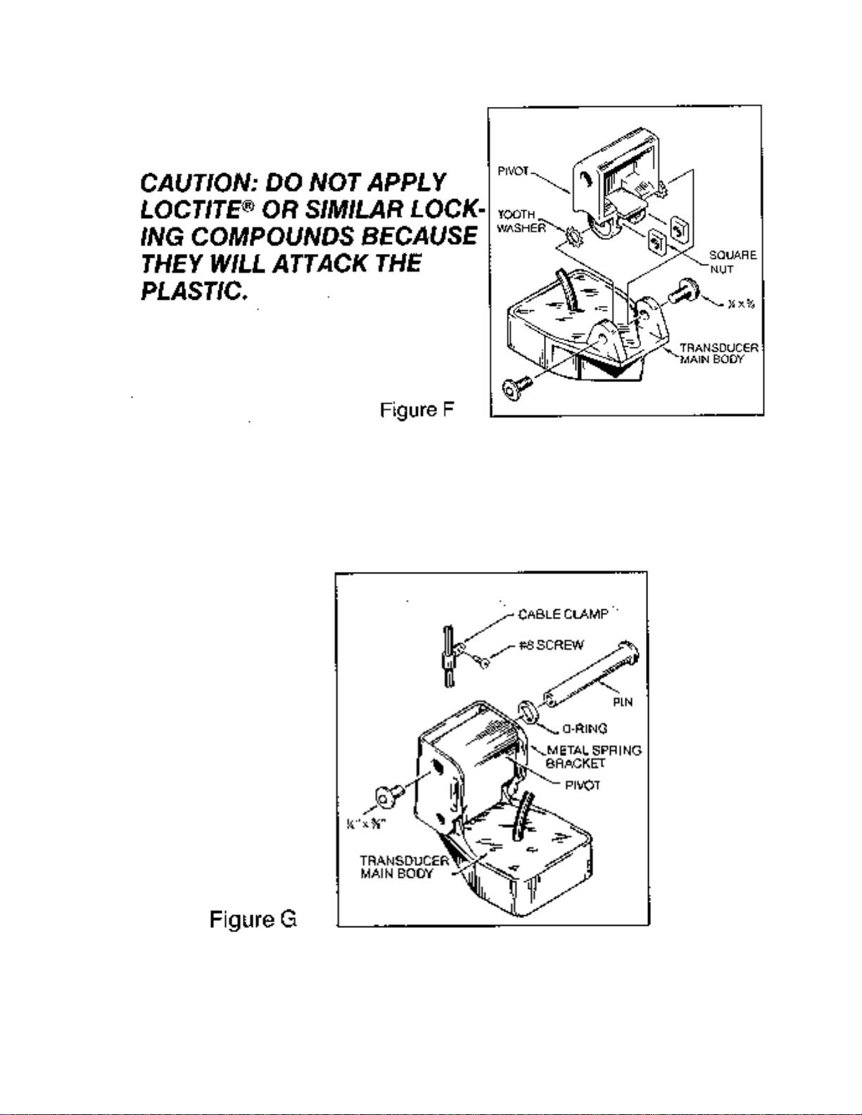
TRANSDUCER PIVOT ASSEMBLY - Assemble the pivot to the transducer main body using the
two ¼”x5/8” allen head screws, two 3/8” tooth washers and two, ¼” square nuts. Make sure the
tooth washers are sandwiched between the transducer main body and the pivot. The square nuts
are trapped inside the pivot and will not rotate as the allen head screws are tightened.
HOWEVER, DO NOT TIGHTEN AT THIS POINT. (See Figure F)
Page 11
Step 4
TRANSDUCER ASSEMBLY - Insert the transducer assembly into the metal bracket from the
bottom. Push up until the holes in the plastic pivot align with the uppermost holes in the bracket.
Slide the O-ring on to the headed pin and insert it through the two parts. Assemble by screwing
the ¼”x3/8” allen head screw into the end of the pin and tighten. (See Figure G)
Step 5
ANGLE ALLIGHMENT- Set the transducer angle so that it is parallel with the bottom of the boat
hull. Once proper alignment is achieved, tighten the two allen head screws using the 5/32” allen
Page 12

wrench provided. The screws are visible through the access holes on each side of the metal
bracket. Check to make sure the transducer main body is rigidly fastened to the pivot. (See
Figure H)
Step 6
CHECK POSITION OF TRANSDUCER- At this point, check to see that the bottom of the
transducer is a minimum of ¼” below the bottom of the transom. (However, as noted in STEP 2,
the top of the transducer can not fall below the bottom of the transom ). If it is not, remove the
transducer assembly from the metal bracket by removing the pin installed during STEP 3.
Loosen the metal bracket mounting screws, re-position the bracket utilizing it’s slotted holes,
tighten and re-assemble. It may be necessary to replace the silicone sealant after this adjustment
is made.
NOTE: It may be necessary to make several high speed runs to adjust transducer either
UP/DOWN or to re-adjust the angle to achieve optimum results.
Step 7
CABLE CLAMPS- Install cable clamps as necessary by drilling a 1/8” dia. hole for the # 8 screw
supplied.
2. INSIDE HULL MOUNTING PROCEDURE
Warning: In order to achieve proper results with this type installation, it is important that the
transducer be mounted by someone familiar with the use of two part epoxy adhesives. For this
reason, Techsonic Industries, Inc. will not be responsible for any damage due to the mounting of
your transducer in this manner.
NOTE: An Epoxy Kit (Part N. EPK) is available from Humminbird. This Epoxy Kit has been
formulated for Inside Hull Transducer Installation.
1. Select as flat an area as possible near the aft end and center of boat where the hull is thin
and not double. If the bottom has a runner down the center of boat, select an area to one side
of the runner, but as close to the runner as possible.
2. Clean the inside of the boat with lacquer thinner in the area transducer is to be mounted.
Outside of boat in this area should also be cleaned. ( Not with lacquer thinner ).
3. Put approximately one inch of water in the bottom of the boat.
4. Put transducer in the water. The bottom of the transducer should be in a flat area and should
be in good contact with the bottom of the boat.
5. Operate the LCR with the boat operating at high speed. The transducer may have to be
moved in order to find an area where satisfactory operation is observed.
Page 13

6. When an area is found that produces satisfactory operation, mark the location of the
transducer.
7. Remove the water and transducer and clean the marked area and the bottom of the
transducer thoroughly.
8. Using the Humminbird Epoxy Kit or equivalent, mix an ample amount of epoxy without
causing it to bubble and pour it in the area the transducer is to be mounted. The puddle
should be larger than the bottom of the transducer.
9. Coat the bottom of the transducer with epoxy, then put it in the center of the puddle and push
down on the transducer while moving it around in a circular motion. This forces out any air
bubbles that may be trapped between the bottom of the transducer and the hull of the boat.
10. Let epoxy cure then the transducer is ready to operate. No water is now required in the
bottom of the boat and gas and oil that is spilled inside of the boat will not degrade
performance as it will if the transducer is placed only in water.
CAUTION: Do not use the silicone seal or any soft adhesive to bond the transducer to the
hull. This will reduce the sens itivity of the unit.
4. TROLLING MOTOR MOUNTING PROCEDURE
A “Trolling Motor Transducer” is designed to be mounted on the foot of the trolling motor with
the aid of an adjustable clamp, included standard. Your trolling motor transducer will give
excellent reading with no interference from the electric motor. Some boat manufacturers are now
glassing in a second transducer beneath the front deck for thru the hull reading of the forward
mounted depth sounder. This installation also serves a dual purpose in that a fisherman can run
his big motor at idle speed and use his front depth sounder to scan for submerged stumps or
obstacles. Such a practice can often prevent damage to props and lower units of the big
outboard.
CAUTIONS
1. Occasionally the “eye“ of your transducer may become dirty from storage or from contact
with oils present in boats or marina environments. (Oil will cause the “eye” to lose the
intimate contact with the water which is necessary for efficient operation.) The “eye” may be
cleaned with liquid detergent.
2. Improper installation of the transducer can alter the efficiency and accuracy of the entire
system.
3. If your boat of transducer is out of the water for a period of time, it may take a short period of
time for the transducer to become thoroughly “wetted” when returned to the water. Also, reentry may cause turbulence which will create air bubbles in the “eye” of the transducer. The
bubbles will disappear in a short time or can be removed by rubbing the transducer “eye” with
your fi ngers while the transducer is in the water.
4. If your instrument should fail to function, be sure to check all the electrical connections before
removing the transducer or calling a serviceman.
Page 14

5. Inspect your transducer cable and make sure that it has not been cut or damaged to the point
where it will affect the performance of the transducer. A slight nick or cut, exposing the outer
cable, can be repaired by wrapping with electrical tape. A transducer can be damaged if the
inner cable and outer cable are allowed to make contact. Such a problem can sometimes be
corrected by properly splicing the coaxial cable. This should only be attempted by a qualified
service technician.
6. If your LCR is not working properly and you suspect the problem might be in your transduc er,
we would recommend you borrow a unit from a friend and try it on your boat. If the symptoms
are the same, you can almost be certain that the problem is in the transducer.
INSTALLING THE LCR
The LCR should be mounted on a flat, solid surface for maximum stability. The low profile swivel
mount has four holes drilled in the base. It is recommended that all four holes be used.
Position the swivel base and drill four ¼” diameter holes. Note: The LCR hole pattern Is the same
as for all Humminbird flasher units. Use hardware provided to mount this base to the boat.
Next place the gimbal bracket on the swivel base and attach with four small machine screws,
provided.
Place the LCR in the gimbal mount and make certain the rubber washers provided are placed
between the unit and the gimbal bracket Important: Note which side of the gimbal faces forward.
(Slots on gimbal bracket go towards rear). Also, rubber washer must be located between the unit
and the gimbal bracket.
Install the mounting knobs and tighten snugly. The unit can now be swiveled and tilted to any
desired position.
Page 15

Page 16

however, this method is not recommended since the unit cannot be rotated.
OTHER MOUNTING OPTIONS
1. The LCR gimbal bracket can also be mounted on the SM-4, quick disconnect swivel mount.
2. The LCR gimbal bracket can also be mounted directly to the dash without the swivel mount,
INSTALLING THE CABLES
Your LCR comes equipped with Humminbird’s new Angle-Lock power and transducer
connectors. The power connector is identified with the letter P on the back of the plug.
Page 17

It plugs into the outlet on the back of the unit marked “Power”. The transducer connector is
identified with the letter T and plugs into the outlet on the back of the unit marked “Transducer”.
Note: An adapter (AD-4) is available to allow use of an old waterproof (BNC) transducer with the
LCR, but be sure that the transducer is a 16degree. A 32 degree transducer cannot be used.
A 11/8” hole must be drilled to pull through the transducer connector. After drilling the hole, pull
the transducer connector up through the hole. If you are installing two units, both transducer
connectors can be pulled through this 1 1/8” inch hole. Next, push the power cable wires down
through the hole. A hole cover has been provided which will dress and hold the wires. Install the
hole cover after determining the necessary wire length from the hole.
The power cable has a red lead to the positive (+) post and the black lead to the negative (-) post.
Install a 1 amp fuse between the red cable and positive post of your 12-volt battery.
If a fuse panel is available, we recommend wiring the power cable into the fuse panel. Note: The
LCR must be fused separately from any other accessory.
Your Angle-Lock connectors can only be plugged in one way. Position the connector so the letter
P or T can be read and the 90 degree bend is pointed downward. Push the connector in as far as
it will go. Turn the positive locking ring as far as it will go clockwise until you feel it lock. locking
ring as far as it will go clockwise until you feel it lock. Your connector is now locked into place.
Note: For easy access to the connectors, simply loosen the mounting knobs and tilt your LCR
forward. The connectors are now in full view and easy to plug or unplug.
TESTING YOUR UNIT AND TRANSDUCER INSTALLATION
After installing the unit, transducer, and cables, you are ready to test the installation. You should
put your boat in t he water to test the unit because the transducer cannot transmit and receive
properly through air.
INITIAL UNIT TESTING
With your boat in the water at idle or at a very slow speed, turn your LCR on by pushing the
“Power” button. The LCR’s computer will automatically adjust the sensitivity and depth range so
Page 18

that in about one second you will see images appear on the right side of the display and moving
to the left.
TROUBLE SHOOTING: If nothing happens when the “Power” button is pushed, check your
electrical connections and fuse. Also check that the red wire on the power cable is connected to
the positive battery terminal and that the black wire is connected to the negative battery terminal.
If these wires are reversed it will not damage the LCR . It is normal if when reversing the boat, the
bottom return is lost, since air from the prop is being forced under the transducer. Remember the
transducer cannot transmit through air.
TROUBLE SHOOTING: If the display comes on when the “Power” button is pushed but no
bottom information is seen, check that the transducer connector is securely locked to the rear of
the LCR. Also insure that the transducer is completely submerged. A transducer cannot work
properly in air or through air bubbles in the water.
TROUBLE SHOOTING: In very shallow water, the bottom reading might have gaps of the range
might change to a deeper range. This is normal in about two feet of less. The automatic mode
cannot “lock” onto the bot tom in very shallow water.
TROUBLE SHOOTING: If the LCR comes on without pressing the “Power” button, carefully
inspect the transducer cable. This condition will be seen if the outer jacket of the cable has been
cut and is touching any metal piece of the boat.
TRANSDUCER INSTALLATION TEST
After verifying that your LCR is working properly, you are ready to increase boat speed to test
the transducer installation. As you increase boat speed the LCR should give a continuous bottom
return. With a proper transducer installation your LCR will perform at speeds up to 75 miles per
hour.
TROUBLE SHOOTING: If at high speeds the bottom return is not continuous or there are gaps
in the bottom, then the transducer installation or location is such that air is going under the
transducer face. Refer back to the transducer mounting procedure for adjustments or for other
mounting options.
TROUBLE SHOOTING: If at high speed and high sensitivity setting the display begins to
blacken, then cavitation noise from the propeller is being received by the transducer. The
transducer should be moved away from the prop or to another location to reduce the cavitation
noise.
TROUBLE SHOOTING: If when making a hard turn, the bottom reading is lost, it is the result of
the transducer coming out of the water during the turn.
OPERATIONAL INSTRUCTIONS
The LCR4x6, while being a technically advanced, state-of-the-art depth sounder. Is probably the
easiest unit to operate. Only 7 buttons control all of the unit’s features.
1. This button turns the unit on and off. Pressing it once turns the unit on. Pressing it again turns
the unit off.
2. This button stops or freezes the display. Pressing it once stops the display. Pressing it again
starts it back up.
3. This button turns the night light on and off. Pressing it once turns the light on. Pressing it
again turns it off.
4. This button allows you to select any of eight functions for easy adjustment right on the unit’s
screen.
5. This button allows you to move a function up or increase it.
6. This button allows you to move a function down or decrease it. It is also the “store” key for
screen memory.
7. This button allows you to turn a feature on and off.
Page 19

SELECTING AND OPERATING THE FUNCTIONS
Pressing the button will result in one of eight different menus of the LCR4x6 functions to be
displayed on the screen. Each time the button is pressed a different menu will appear. After
the eighth different menu is displayed, the first menu will be displayed again. Unless the , ,
or button is pressed, no function will be changed. If no button is pressed after about three
seconds, the menu will disappear. Pressing the button again will cause the last menu to be
displayed again or holding it down will cause the menu to be displayed as long as it is held down.
If no function is being displayed pressing the , , or key will cause the last menu to be
displayed, assuming that button is active, that is, that it can change the function.
THINGS TO KNOW ABOUT DISPLA Y SPEED
A. There are eight display speeds, indicated by the eight bars on the display.
B. When the LCR is turned on the unit will be advancing at the maximum display speed.
C. When a maximum or minimum speed is reached, a chirping sound will be heard.
1. AUTOMATIC AND MANUAL OPERATION AND SENSITIVITY ADJUSTMENT
Page 20

THINGS TO KNOW ABOUT AUTOMATIC AND MANUAL OPERATION
A. When the LCR is turned on the unit is in the automatic mode. This is indicated on the menu
and in the lower left area of the screen. In the Automatic Mode the sensitivity
Is continuously adjusted automatically, the correct depth range is automatically selected and the
area below the bottom return is blackened out making the bottom easy to see.
B. There are 16 levels of sensitivity adjustment, indicated by the bars on the menu and in the
lower left area of the display.
C. Pressing either the , , or the button will put the LCR in the Manual Mode.
D. In the Manual Mode the digital bottom reading goes off and the automatic range change is
off. Also the area below the bottom is no longer blacked out, therefore a second return or
double echo can be displayed if desired (see Figure 16). Also, the hardness of the bottom
can sometimes be determined by the thickness of the second bottom return. For example, a
hard or rock bottom will give a wider return as compared to a soft or muddy bottom.
Page 21

E. In the Manual Mode it is possible to have the sensitivity set too high such that reflection from
suspended matter or air bubbles will begin to black out the display.
3. DEPTH RANGE
Page 22

THINGS TO KNOW ABOUT DEPTH RANGE
A. In the automatic mode the proper depth range is found as soon as the unit is turned on.
B. As you move into deeper water and the bottom goes off the screen, the next deeper depth
range will automatically be activated. Also, as water becomes shallower reaching the top one
third of the screen the depth range will automatically change to the next shallower scale.
C. As the depth range changes, the scales to the right of the display will also change indicating
the maximum depth of that range and also intermediate depths at one-third and two-thirds of
the full scale.
D. The LVR4x6 has six depth ranges: 0-15 feet, 0-30 feet, 0-69 feet, 0-120 feet, 0-180 feet, and
0-240 feet. You may manually change the depth range by pressing the , or buttons.
E. In the Automatic Mode, if you attempt to change to a depth range which is less than the
actual bottom depth, the computer will automatically change the depth range back to the
proper position. For example, if you are in 40 feet of water and you change the depth range
to 30 feet, the computer will automatically change back to the 60 foot range.
F. The button, while on the depth range menu, will turn the Automatic Mode on and off. It has
the same function as the button used on the sensitivity menu.
G. In the Manual Mode the automatic range change is not active. This means you must
manually set the depth range by pressing the or buttons.
4. BOTTOM ALARM
Page 23

THINGS TO KNOW ABOUT BOTTOM ALARM
A. The alarm setting is shown digitally (in numbers) on the menu and graphically ( by the
vertical bar ) on the right side of the display. It is set at 5 feet when the unit is first turned on.
B. When the bottom alarm is turned off it is indicated on the menu and the vertical bar
disappears on the right side of the display.
C. Pressing the or button once will change the setting by one division. Holding either
button down will cause the setting to change rapidly. You will notice that the increment s of
change will vary depending on the depth range. For example, on the 0 to 15 foot range the
setting will change about 3 inches each time the or button is pressed while on the o to
240 foot range increment is 4 feet.
D. The alarm setting may be set from 1 foot to 240 feet.
E. In the Automatic Mode the Bottom Alarm will sound a continuous Alarm when the bottom is
equal to or less than the setting. Fish will not trigger the bottom alarm.
F. In the Manual Mode wither the bottom or fish can trigger the alarm. If the bottom depth
becomes equal to or less than the alarm setting, a continuous Alarm will sound. If a fish
enters the Alarm range, a short quick Alarm will sound.
G. If the Bottom Alarm is turned off and then back on again before the unit is turned off, it will be
set at the previous setting.
5. FISH ALARM
Page 24

THINGS TO KNOW ABOUT FISH ALARM
A. The Fish Alarm will give a short alarm sound when a return is detected between the boat and
3 inches from the bottom. It will not alarm on the bottom.
B. When the Fish Alarm is on it is indicated on the menu and also on the right side of the display
by the word “FISH”.
C. The Fish Alarm is operational only while the LCR is in the Automatic Mode. See paragraph F
under Bottom Alarm for use of the alarm in the Manual Mode.
D. The Fish Alarm may occasionally sound when no target is displayed. This can happen when
a target is detected close to the bottom but is too close to be seen on the display because of
the range selected. It can also happen when the display sweep speed is slow. Such that the
target was detected but is gone by the time the display is updated.
6. ZOOM
Page 25

THINGS TO KNOW ABOUT ZOOM
A. When Zoom is turned on, the screen will automatically split showing the full depth scale
information on the right and the ex panded view corresponding to the portion of the Zoom
Cursor on the left (see Figure 2).
B. When Zoom is turned on, it is indicated on the menu and at the lower middle part of the
display.
C. Pressing the or button once will move the Zoom Cursor one division. Holding the
button down will cause the Cursor to move continuously.
D. The size of t e Zoom Range is automatically selected, depending on the depth range, as
shown below with the display resolution for each range:
Depth Zoom Range Each
Dot
Range Size
Equals
0-15, 0-30 7.5 Feet ¾
Inch
0-60, 0-120 15 Feet 11/2
Inches
0-180, 0-240 30 Feet 3
Inches
E. The exact depth of the top and bottom of the Zoom Range is displayed in the upper and
lower left corners of the screen. As the Zoom Cursor is moved up and down these numbers
will change to indicate the exact setting of the Zoom Range. These depth indicators will be
very useful in pinpointing the exact depth of fish or structure.
Page 26

F. Zoom may be activated at any time. While learning to use Zoom it may be easier to press the
button to freeze the display after positioning the Zoom Cursor. This will give you time to study
the display. NOTE: If the display is stopped, the screen will not update (change) until the
button is pressed again.
G. Remember that because of the LCR’s Total Screen Update, even while you are using Zoom,
no information is being lost. You can turn Zoom off, go to any depth range and see all the
information just as if you had been on that depth range all along.
THINGS TO KNOW ABOUT BOTTOM LOCK
A. When Bottom Lock is turned on, the screen will automatically split showing the full depth
scale information on the right and the expanded view from the bottom looking up on the left
(See Figure 23).
Page 27

B. When Bottom Lock is turned on it is indicated on the menu and at the lower middle part of
the display.
C. Bottom Lock can only be used in the Automatic Mode.
D. Bottom Lock will give an expanded view up from he bottom. The size of the expanded area
is determined by the depth range, just as in Paragraph D under Zoom above. As the bottom
depth changes, the Zoom Range will also change to maintain its position to the bottom.
E. In Bottom Lock the bottom will always come onto the screen one third up from the bottom of
the display (see figure 23). As the bottom depth changes the expanded view will also
change so that the actual bottom contour can be seen.
F. The actual depth of the Zoom Range is indicated in the upper and lower left portion of the
screen. Since the Zoom Range always stays on the bottom, these depths will change as the
bottom depth changes.
G. Bottom Lock is a very valuable feature If you are looking for bottom structure or fish close to
the bottom. Bottom Lock is easiest to use on a relatively smooth bottom or at slow trolling
speeds.
Page 28

THINGS TO KNOW ABOUT SCREEN MEMORY
Page 29

A. You can store 16 half screens in memory. Once stored, the Screen Memory will remain
virtually forever. You can disconnect power from the LCR, store it over the Winter, bring it
back out in the Spring and still be able to recall stored information.
B. Use the to select one of 16 memory locations. When Screen Memory is turned on
(indicated on the menu and at the lower middle of the display ) the screen will automatically
split to display the screen in memory on the left side and the full depth scale information on
the right.
C. If Zoom or Bottom Lock is on when Screen Memory is turned on, then the right half of the
screen will show the Zoom or Bottom Lock information.
D. To store a screen, first select a memory location number. Then with Screen Memory turned
on, press the button. Any information previously stored in the memory location will be
erased and replaced with the new information currently being displayed on the right half of
the screen.
E. Split Screen will allow you to compare a recalled screen (from memory) with the current
reading. This will be useful in locating the same spot and comparing previous conditions to
the present.
BUILT -IN SIMULATOR
Your LCD4x6 has a built-in simulator. This simulator will display a typical underwater scene
which can be used for demonstration or for learning how to use and understand your unit.
To activate the simulator, the unit must first be turned off. Next, push in the button for one to
two seconds, until you hear the chirping sound. Then release the button and the simulated
display will begin.
In the simulation mode all buttons and features can be used. It should be noted, however, that
increasing or decreasing the sensitivity setting will not affect the information being displayed.
CARING FOR YOUR LCR:
Since your Humminbird LCR is completely waterproof, it can be cleaned with soap and water or
hosed off after salt water use with no fear of damage to the unit or its electronics. When cleaning
the lens, it is suggested you use a chamois cloth and a non-abrasive cleaner such as Windex Do
not wipe while dirt or other gritty material is on the lens. Care should be exercised to avoid
scratching the lens. Keep chemicals such as bug repellant, ammonia or gasoline away from the
LCR case and lens.
As with any electrical instrument, do not leave your LCR on the dash board or rear window
area of the car. The sun can create extremely high temperat ures which can damage the case
and internal electrical components. During extended periods of non-use, such as Winter, you
should store the LCR and other removable depth sounders in the house or garage. This will help
prolong the good appearance and operat ion of these instruments.
LEARNING TO READ THE DISPLAY
The following illustrations show some typical displays with bottom, structure, and fish returns.
These should help you in interpreting the information being displayed on your LCR4x6.
Page 30

Brush and standing timber will appear as shown in the display above. The speed of the boat
and display sweep speed will have a large effect on the way this information is displayed. For
example, at a slow boat speed and a fast sweep speed the standing timber will appear wider. At
a fast boat speed and a slow sweep speed some of the information will be missed.
Page 31

With Bottom Lock the wreck and the fish are clearly displayed on the left side of the screen
which shows an expanded view 20 feet up from the bottom (screen is from 142 feet to 172 feet).
Page 32

Thermocline is a temperature change at a certain depth in the water. In some conditions the
sonar waves will actually reflect or bounce off this temperature change and therefore it will be
displayed on the LCR as shown above. Normally a high sensitivity setting is required to show the
thermocline; therefore, if you want to see the thermocline go to the Manual Mode and increase
the sensitivity level.
OPTIONAL TEMPERATURE AND SPEED GAUGES
Your LCR is designed to work well with an optional surface temperature gauge. Part Number
TG-LCR, or an optional Trolling Speed Indicator, Part Number TSI-LCR. Fig. 26 illustrates the
three basic parts of these gauges -the cable interconnection between the electronics and the
LCR, the electronic housing, and the probe cable assembly.
Page 33

The surface temperature gauge is a valuable fishing and boating aid. It will measure water
temperature in one-tenth of degrees and display the reading on the LCR screen. The probe and
computer controlled electronics have been designed for an accurate indication and an extremely
fast response time.
The Trolling Speed Indicator will give very accurate low speed readings, in tenths below 10
mph., unlike ordinary speedometers. An accurate trolling speed can make the difference in
catching fish. The TSI-LCR also gives accurate high speed readings to 75 mph.
If you do not have a surface temperature gauge of a trolling speed indicator, see your LCR
dealer or call the Humminbird Customer Service Department’s Toll Free number
Listed in the front of this manual. If you want both the TG -LCR and TSI-LCR an accessory
switch is available to allow you to use both and select which one is being displayed on the
screen.
SHOULD YOU NEED SERVICE
If, aft er reading the troubleshooting guide, you determine your Humminbird needs factory
service, please attach the following information to the unit and send it to the address below.
Name (Please Print)
Street Address
City State Zip
Unit Purchase Date
Page 34

Home Telephone Work Telephone
Please describe briefly the problem:
Techsonic Industries, Inc.
Service Department
Three Humminbird Lane
Eufaula, AL 36027
The best products in the industry are backed by the best service policy in the industry. Even
though you’ll probably never need to take advantage of our incredible service guarantee, it’s good
to knnow that we back our units this well. We do it because you deserve the best.
One-Year Full Warranty
First year repairs on your unit will be made absolutely FREE (physical damage not included)
Limited Maximum Service Charge
After the warranty period,, a limited maximum service charge is the most you will pay for each
repair (physical damage and missing parts not included).
Factory- Trained Technicians
All repair work is performed by factory - trained technicians to meet exacting factory
specifications.
Strictest Factory Testing
Factory - serviced units go through the same rigorous quality- control inspections and full burn- in
as new units.
 Loading...