

Page 1
Page 2

Thank You!
Thank you for choosing Humminbird®, America's #1 name in fishfinders.
Humminbird® has built its reputation by designing and manufacturing
top-quality, thoroughly reliable marine equipment. Your Humminbird® is
designed for trouble-free use in even the harshest marine environment. In
the unlikely event that your Humminbird® does require repairs, we offer an
exclusive Service Policy - free of charge during the first year after purchase,
and available at a reasonable rate after the one-year period. For complete
details, see the Warranty section in this manual. We encourage you to read
this installation and operations manual carefully in order to get full benefit
from all the features and applications of your Humminbird® product.
Contact our Customer Resource Center at either 1-800-633-1468 or visit our
web site at humminbird.com.
WARNING! This electronic chart is an aid to navigation designed to facilitate the use of
authorized government charts, not to replace them. Only official government charts and
notices to mariners contain all of the current information needed for the safety of
navigation, and the captain is responsible for their prudent use.
WARNING! This device should not be used as a navigational aid to prevent collision,
grounding, boat damage, or personal injury. When the boat is moving, water depth may
change too quickly to allow time for you to react. Always operate the boat at very slow
speeds if you suspect shallow water or submerged objects.
WARNING! Disassembly and repair of this electronic unit should only be performed by
authorized service personnel. Any modification of the serial number or attempt to repair
the original equipment or accessories by unauthorized individuals will void the warranty.
WARNING! This product contains chemicals known to the State of California to cause
cancer and/or reproductive harm.
WARNING! Do not travel at high speed with the unit cover installed. Remove the unit
cover before traveling at speeds above 20 mph.
NOTE: Some features discussed in this manual require a separate purchase, and some
features are only available on international models. Every effort has been made to clearly
identify those features. Please read the manual carefully in order to understand the full
capabilities of your model.
ATTENTION INTERNATIONAL CUSTOMERS: Products sold in the U.S. are not
intended for use in the international market. Humminbird® international units
provide international features and are designed to meet country and regional
regulations. Languages, maps, time zones, units of measurement, and warranty
are examples of features that are customized for Humminbird® international
units purchased through our authorized international distributors.
To obtain a list of authorized international distributors, please visit our web
site at www.humminbird.com or contact our Customer Resource Center at
(334) 687-6613.
XM WX® is a registered trademark of XM Satellite Radio and Weather to the Power of X® is a
registered trademark of XM Satellite Radio Inc. All rights reserved.
ProMap™ and LakeMaster® are trademarked by or registered trademarks of Waypoint
Technologies, Inc.
Navionics® Gold, HotMaps™, and HotMaps™ Premium, Navionics® Classic Charts, and Platinum™
Cartography are trademarked by or registered trademarks of Navionics®.
800 Series™, 900 Series™, Cannon®, CannonLink™, Contour XD™, Down Imaging™, DualBeam
PLUS™, Fish ID+™, HumminbirdPC™, Humminbird®, InterLink™, One-Touch® Zoom,
QuadraBeam PLUS™, RTS™ Window, Side Imaging®, SmartCast®, SwitchFire™, Structure ID®,
Total Screen Update™, UniMap™, WeatherSense®, WhiteLine™, and X-Press™ Menu are
trademarked by or registered trademarks of Humminbird®.
© 2010 Humminbird®, Eufaula AL, USA. All rights reserved.
i
Page 3

Table of Contents
Introduction 1
How Sonar Works ....................................................................................................................1
High Definition Side Imaging® Sonar
DualBeam PLUS™ Sonar
QuadraBeam PLUS™ Sonar
Universal Sonar 2 ......................................................................................................................4
How GPS and Cartography Work............................................................................................4
Fishing System Configuration..................................................................................................5
Accessory Bus ..........................................................................................................................5
Video-Out and RS 232 Connectors..........................................................................................6
(858c, 898c SI, 958c, 998c SI)..........................................................3
(898c SI and 998c SI only)............................................2
(optional-purchase QuadraBeam PLUS™ transducer only) ..........3
Installation Overview 6
Control Head Installation 6
Gimbal Mounting the Control Head........................................................................................7
Connecting the Control Head Power Cable to the Boat......................................................11
Transducer Installation Overview 12
858c & 958c Transom Mount Transducer Installation
DualBeam PLUS™ Transducer, XNT 9 20 T (858c and 958c only) 13
Overview..................................................................................................................................13
Locating the transducer mounting location..........................................................................14
Preparing the Mounting Location ........................................................................................15
Assembling the Transducer and Initial Mounting................................................................16
Routing the Cable ..................................................................................................................20
Test and Finish the Installation..............................................................................................21
Locking Down the Transducer (Optional)..............................................................................23
858c & 958c Inside the Hull Transducer Installation
DualBeam PLUS™ Transducer, XNT 9 20 T (858c and 958c only) 24
Locating the transducer mounting location ........................................................................24
Trial installation ......................................................................................................................25
Routing the cable....................................................................................................................26
Permanently mounting the transducer ................................................................................26
898c SI & 998c SI Transom Mount Transducer Installation
Side Imaging Transducer, XHS 9 HDSI 180T (898c SI or 998c SI only) 27
Overview..................................................................................................................................28
Locating transducer mounting location................................................................................28
Mounting the transducer bracket to the boat......................................................................29
Attaching the pivot to the transducer ..................................................................................30
Mounting the transducer pivot assembly to the bracket ....................................................30
Adjusting the running position of the transducer................................................................31
Routing the cable....................................................................................................................32
Testing the installation ..........................................................................................................33
Trolling Motor Transducer Installation 33
Trolling Motor Transducer Options........................................................................................33
Test and Finish the Transducer Installation ..........................................................................33
GPS Receiver Installation Overview 34
Stem Mounting with an Existing 1" - 14 Thread Stem........................................................35
Access Under Mounting Location ........................................................................................36
No Access Under Mounting Location ..................................................................................36
Finish Routing the Cable and Check GPS Receiver Operation............................................37
ii
531743-1_B
Page 4

Table of Contents
Testing the System Installation 38
Power On the Control Head 39
What’s on the Control Head 39
Key Functions 40
POWER/LIGHT Key..................................................................................................................40
VIEW Key ................................................................................................................................40
MENU Key ..............................................................................................................................40
4-WAY Cursor Control Key (RIGHT, LEFT, UP, or DOWN Cursor Keys)................................41
VIEW PRESET Keys ................................................................................................................41
EXIT Key ..................................................................................................................................41
INFO Key ................................................................................................................................42
MARK Key................................................................................................................................42
GOTO Key ................................................................................................................................42
ZOOM (+/-) Keys ....................................................................................................................42
Multi-Media Card (MMC)/SD Slots 43
Add Maps to Your Fishing System ........................................................................................43
Update Software ....................................................................................................................44
Export Navigation Data ..........................................................................................................44
What’s on the Sonar Display 45
Understanding the Sonar Display..........................................................................................46
Real Time Sonar (RTS™) Window ........................................................................................46
SwitchFire™ ............................................................................................................................46
Freeze Frame and Active Cursor............................................................................................47
Instant Image Update ............................................................................................................47
Sonar Bottom Presentation....................................................................................................47
What’s on the Side Imaging® Display (898c SI and 998c SI only) 48
Understanding the Side Imaging® Display ..........................................................................49
Side Imaging® Frequencies and Coverage............................................................................50
For Best Performance ............................................................................................................51
On the Water Interpretation ..................................................................................................51
Views 53
Side Imaging® View
Down Imaging™ View
Sonar View ..............................................................................................................................57
Sonar Zoom View....................................................................................................................58
Split Sonar View......................................................................................................................59
Snapshot and Recording View
Side Beam View
Bird’s Eye View........................................................................................................................67
Chart View ..............................................................................................................................68
Combo Views ..........................................................................................................................69
Combo Views: Functions........................................................................................................69
Side Imaging/Sonar Combo View
Chart/Bird’s Eye Combo View................................................................................................70
Chart/Chart Combo View ......................................................................................................70
Chart/Sonar Combo View ......................................................................................................71
Chart/Side Imaging Combo View
Down Imaging™/Side Imaging® Combo View
(898c SI and 998c SI only)
(898c SI and 998c SI only)
(optional-purchase MMC/SD card required)
(optional-purchase QuadraBeam PLUS™ transducer required)
(898c SI and 998c SI only)
(898c SI and 998c SI only)
....................................................................55
................................................................56
........................60
..............................................69
..............................................71
(898c SI and 998c SI only)
..........................72
..................65
iii
Page 5

Table of Contents
Chart/Down Imaging™ Combo View
Down Imaging™/Sonar Combo View
Down Imaging™/Side Imaging/Sonar Combo View
View Orientation ....................................................................................................................74
(898c SI and 998c SI only)
(898c SI and 998c SI only)
(898c SI and 998c SI only)
........................................72
........................................73
................73
Viewing Cartography 74
Introduction to Navigation 76
Waypoints, Routes, and Tracks..............................................................................................76
Save, Edit, or Delete a Waypoint ..........................................................................................77
Navigate to a Waypoint or Position ......................................................................................78
Add a Waypoint Target or Trolling Grid ................................................................................78
Save, Edit or Delete a Route ..................................................................................................79
Save or Clear a Current Track ................................................................................................80
Edit, Delete, or Hide Saved Tracks ........................................................................................80
Man Overboard (MOB) Navigation........................................................................................81
The Menu System 82
Start-Up Options Menu 82
Simulator ................................................................................................................................83
System Status ........................................................................................................................83
Self Test ..................................................................................................................................83
Accessory Test ........................................................................................................................84
GPS Diagnostic View..............................................................................................................84
X-Press™ Menu 85
Main Menu 85
Quick Tips for the Main Menu ..............................................................................................86
Note for all Menu Settings ....................................................................................................86
User Mode (Normal or Advanced) ........................................................................................87
Sonar X-Press™ Menu 88
Active Side
Split Position
Sensitivity ................................................................................................................................89
Upper Range
Lower Range ..........................................................................................................................90
Chart Speed ............................................................................................................................90
Quad Layout
Bottom Lock
Bottom Range
Cancel Navigation
(Combo Views only)
(Combo Views only)
(Advanced: Sonar, Split Sonar and Active Sonar Side Views only)
(with optional-purchase QuadraBeam PLUS™ Transducer, Side Beam View only)
(Sonar Zoom View only)
(Sonar Zoom View only, when Bottom Lock is On)
(only when Navigating)
..............................................................................................88
..........................................................................................88
....................................................................................91
........................................91
............................................................................91
..................89
Side Imaging® X-Press™ Menu
(Side Imaging Views only [898c SI, 998c SI])
Active Side
Split Position
SI Side......................................................................................................................................93
SI Sensitivity ............................................................................................................................93
SI Enhance ..............................................................................................................................93
SI Range ..................................................................................................................................94
Chart Speed ............................................................................................................................94
SI Colors ..................................................................................................................................94
iv
(Combo Views only)
(Combo Views only)
..............................................................................................92
..........................................................................................92
............90
92
Page 6

Table of Contents
Down Imaging™ X-Press™ Menu
(Down Imaging™ Views only [898c SI, 998c SI])
Active Side
Split Position
(Combo Views only)
(Combo Views only)
..............................................................................................95
..........................................................................................95
Down Sensitivity ....................................................................................................................96
Upper Range
(Advanced: Down Imaging™ Views only)
........................................................96
Lower Range ..........................................................................................................................97
Chart Speed ............................................................................................................................97
SI Colors ..................................................................................................................................97
Cancel Navigation
(only when Navigating)
............................................................................97
95
Navigation X-Press™ Menu 98
Active Side
Split Position
Waypoint [Name]
Cursor to Waypoint
Save Current Track ..................................................................................................................99
Clear Current Track ................................................................................................................99
Save Current Route
Skip Next Waypoint
Cancel Navigation
Cancel MOB Navigation
Remove Target
Remove Grid
Waypoint [Name]
(Combo Views only)
(Combo Views only)
(Only with an active cursor on a waypoint)
(Chart or Combo View only)
(only when Navigating)
(only when Navigating)
(only when Navigating)
(only if a Target is Active)
(only if a Grid is Active)
(Most recently-created waypoint)
..............................................................................................98
..........................................................................................98
........................................................................100
........................................................................100
..........................................................................100
(only when MOB Navigation is activated)
............................................................................100
....................................................................................100
..............................................99
....................................................................99
....................................100
............................................................101
Snapshot and Recording X-Press™ Menu
(Snapshot and Recording View only)
Start Recording
(optional-purchase MMC/SD Card, Snapshot and Recording View only)............................102
Stop Recording
Delete Image
(optional-purchase MMC/SD Card only) ......................................................102
(optional-purchase MMC/SD Card, Snapshot and Recording View only) ........102
Delete All Images
(optional-purchase MMC/SD Card, Snapshot and Recording View only)............................103
Delete Recording
(optional-purchase MMC/SD Card, Snapshot and Recording View only)............................103
Delete All Recordings
(optional-purchase MMC/SD Card, Snapshot and Recording View only)............................103
Pings Per Second
(optional-purchase MMC/SD Card, Snapshot and Recording View only)............................103
Playback Speed
(optional-purchase MMC/SD Card, Snapshot and Recording View only)............................103
Stop Playback
(optional-purchase MMC/SD Card only) ........................................................104
102
Alarms Menu Tab 105
Depth Alarm..........................................................................................................................105
Fish ID Alarm ........................................................................................................................105
Low Battery Alarm................................................................................................................106
Aux. Temp Alarm
(with optional-purchase temp. probe or Temp/Speed only)
Temp. Alarm ..........................................................................................................................106
Off Course Alarm ..................................................................................................................106
Arrival Alarm..........................................................................................................................107
Drift Alarm ............................................................................................................................107
Alarm Tone ............................................................................................................................107
....................106
v
Page 7

Table of Contents
Sonar Menu Tab 108
Beam Select..........................................................................................................................108
Side View Frequency
(Side Imaging® and Down Imaging™ Views only [898c SI, 998c SI]) ................................
109
Surface Clutter......................................................................................................................109
SwitchFire™ ..........................................................................................................................109
Fish ID+™..............................................................................................................................110
Fish ID Sensitivity..................................................................................................................110
Real Time Sonar (RTS™) Window ......................................................................................111
Sonar Colors..........................................................................................................................111
Bottom View..........................................................................................................................111
Zoom Width
(Sonar Zoom View only)
83 kHz Sensitivity
(Advanced)
..................................................................................112
..............................................................................................112
455 kHz Sensitivity
(Advanced, with optional purchase QuadraBeam PLUS™ transducer) ..................................
Depth Lines
Noise Filter
Max Depth
Water Type
(Advanced)
(Advanced)
(Advanced)
(Advanced)
........................................................................................................113
........................................................................................................113
..........................................................................................................114
........................................................................................................114
112
Transducer Select..................................................................................................................114
Color Bar................................................................................................................................115
Temperature Graph
(Sonar View only, with Temperature input)
Down Imaging™ Beam Width
(Advanced)
..........................................................................115
..........................................115
Navigation Menu Tab 116
Current Track ........................................................................................................................116
Saved Tracks..........................................................................................................................117
Waypoints..............................................................................................................................117
Routes....................................................................................................................................118
Chart Orientation ..................................................................................................................118
North Reference....................................................................................................................118
Waypoint Decluttering
(Advanced)
......................................................................................118
Trolling Grid Rotation............................................................................................................119
Trackpoint Interval ................................................................................................................119
Track Min Distance
(Advanced)
............................................................................................119
Track Color Range ................................................................................................................119
Map Datum
(Advanced)
........................................................................................................120
Course Projection Line..........................................................................................................120
3D View Outline....................................................................................................................120
Export All Nav Data
Delete All Nav Data
(Advanced)
(Advanced)
..........................................................................................120
..........................................................................................120
Continuous Navigation Mode..............................................................................................120
GPS Receiver Override
(Advanced)
......................................................................................120
Chart Menu Tab 121
Lat/Lon Grid ..........................................................................................................................121
Navaids on Bird’s Eye View..................................................................................................121
Chart Select ..........................................................................................................................121
Set Simulation Position
Set Map Offset
Clear Map Offset
Shaded Depth ......................................................................................................................122
Chart Detail Level
(Advanced)
(Advanced)
(Advanced)
(optional-purchase Navionics® charts only)
....................................................................................122
..................................................................................................122
................................................................................................122
............................................123
vi
Page 8

Table of Contents
Map Borders..........................................................................................................................123
Spot Soundings
(optional-purchase Navionics® charts only)
................................................123
NVB Chart Preference ........................................................................................................124
Contour Lines
Depth Colors
Depth Highlight
Depth Highlight Range (+/-)
Water Level Offset
Shallow Water Highlight
Lake List
(optional-purchase LakeMaster® charts only)
(optional-purchase LakeMaster® charts only)
(optional-purchase LakeMaster® charts only)
(optional-purchase LakeMaster® charts only) ........................
(optional-purchase LakeMaster® charts only)
(optional-purchase LakeMaster® charts only)
(optional-purchase LakeMaster® charts only)
................................................124
..................................................124
............................................124
124
........................................124
..............................125
........................................................125
Setup Menu Tab 126
Units - Depth ........................................................................................................................126
Units - Temp
Units - Distance
Units - Speed
(International only)
(with Speed input only)
(with Speed input only)
User Mode ............................................................................................................................127
Language
Triplog Reset
(International only)
(with Speed input only)
Restore Defaults....................................................................................................................127
Select Readouts
Depth Offset
Aux. Temp Offset
Temp. Offset
Speed Calibration
(Advanced)
(Advanced)
(Advanced)
(Advanced)
(Advanced, with Speed paddlewheel only)
..........................................................................................126
..............................................................................126
..................................................................................127
................................................................................................127
..................................................................................127
................................................................................................128
......................................................................................................129
................................................................................................129
......................................................................................................129
............................................129
Local Time Zone
Daylight Saving Time
Position Format
Time Format
Date Format
Digits Format
NMEA Output
(Advanced)
(Advanced)
(Advanced, International only)
(Advanced, International only)
(Advanced)
(Advanced)
................................................................................................129
(Advanced)
........................................................................................129
..................................................................................................130
......................................................................................................130
....................................................................................................130
..........................................................................130
..........................................................................130
Sonar......................................................................................................................................131
Demonstration ......................................................................................................................131
Sound Control ......................................................................................................................131
Video Out ..............................................................................................................................131
Views Menu Tab 132
Accessories Menu Tab 132
Screen Snapshot
AIS
(optional-purchase AIS equipment only)
(optional-purchase MMC/SD Cards only)
........................................................................133
................................................133
Troubleshooting 136
Fishing System Doesn’t Power Up ......................................................................................136
Fishing System Defaults to Simulator with a Transducer Attached ................................136
Display Problems 137
Finding the Cause of Noise 138
vii
Page 9

Table of Contents
1-Year Limited Warranty 139
Humminbird® Service Policy 139
Fishing System Accessories 141
Specifications 142
Glossary 144
Appendix A
Side Imaging® Transducer Mounting Template (XHS 9 HDSI 180 T)
Contact Humminbird® 150
NOTE: Entries in this Table of Contents which list (International Only) are only
available on products sold outside of the U.S. by our authorized international
distributors. To obtain a list of authorized international distributors, please visit
our web site at humminbird.com or contact our Customer Resource Center at
(334) 687-6613.
NOTE: Some of the entries in this Table of Contents may require the purchase
of separate accessories. You can visit our web site at humminbird.com to
order these accessories online or contact our Customer Resource Center at
1-800-633-1468.
149
viii
Page 10

Page 11
Introduction
Your Humminbird® Fishing System is configured as follows:
• Humminbird® 858c Combo: Wide Screen Fishing System with
DualBeam PLUS™ Sonar and Chartplotting. GPS Receiver included.
• Humminbird® 898c SI Combo: Wide Screen Fishing System with
Side Imaging® Sonar, DualBeam PLUS™ Sonar, and Chartplotting.
GPS Receiver included.
• Humminbird® 958c Combo: Ultra Wide Screen Fishing System with
DualBeam PLUS™ Sonar and Chartplotting. GPS Receiver included.
• Humminbird® 998c SI Combo: Ultra Wide Screen Fishing System
with Side Imaging® Sonar, DualBeam PLUS™ Sonar, and
Chartplotting. GPS Receiver included.
How Sonar Works
Sonar technology is based on sound waves. The Fishing System uses sonar
to locate and define structure, bottom contour and composition, as well as
depth directly below the transducer.
Your Fishing System sends a sound wave signal and determines distance by
measuring the time between the transmission of the sound wave and when
the sound wave is reflected off of an object; it then uses the reflected signal
to interpret location, size, and composition of an object.
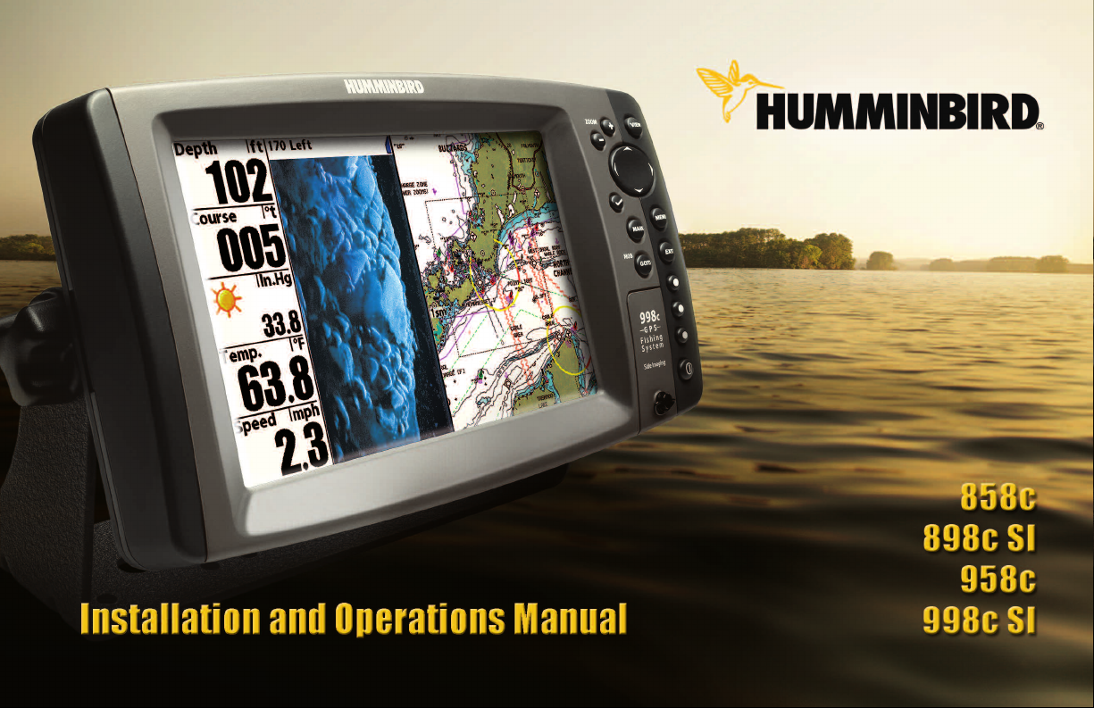
SONAR is an acronym for SOund and
NAvigation Ranging. Sonar utilizes precision
sound pulses or "pings" which are emitted into
the water in a teardrop-shaped beam.
The sound pulses "echo" back from objects in
the water such as the bottom, fish and other
submerged objects. The returned echoes are
displayed on the LCD screen. Each time a new
echo is received, the old echoes are moved
across the LCD, creating a scrolling effect.
When all the echoes are viewed side by side,
an easy to interpret "graph" of the bottom, fish
and structure appears.
Sonar is very fast. A sound wave can travel from the surface to a depth of
240 ft (70 m) and back again in less than 1/4 of a second. It is unlikely that
your boat can "outrun" this sonar signal.
1
Introduction
Page 12
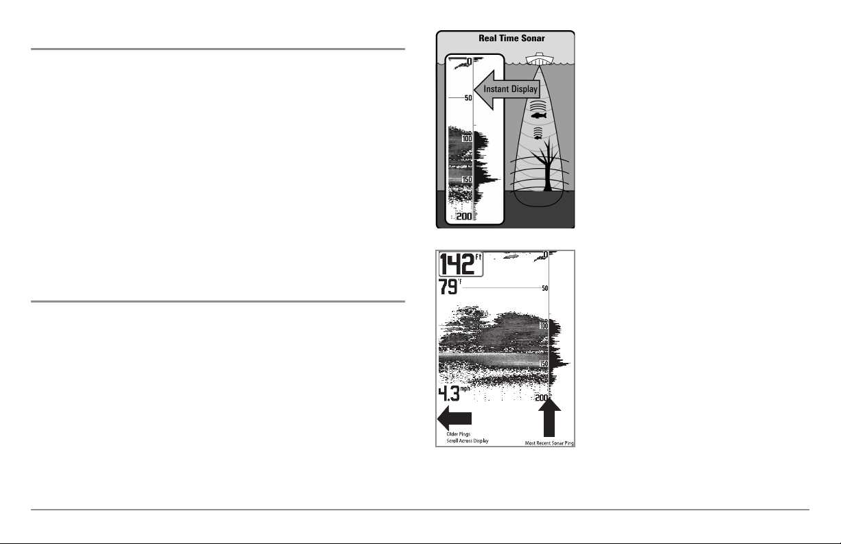
The sound pulses are transmitted at various
60°
8
3kHz
20°
200kHz
86°
4
55kHz
86°
4
55kHz
frequencies depending on the application.
Very high frequencies (455 kHz) are used for
High Definition
Side Imaging
(898c SI and 998c SI only)
® Sonar
greatest definition, but the operating depth is
limited. High frequencies (200 kHz) are
commonly used on consumer sonar and
provide a good balance between depth
performance and resolution. Low frequencies
(83 kHz) are typically used to achieve greater
depth capability.
The 898c SI Combo and 998c SI Combo
use Side Imaging® sonar to provide a
wide yet precise survey of a large area
of water, including detailed bottom
topography and fish-attracting structure
orientation. The Side Imaging®
transducer returns are processed into an
image similar to an aerial photograph.
Typically, the Side Imaging® sonar can
search an area that is 480 feet wide (240
The power output is the amount of energy
generated by the sonar transmitter. It is
commonly measured using two methods:
• Root Mean Square (RMS) measures power
output over the entire transmit cycle.
• Peak to Peak measures power output at the
highest points.
The benefits of increased power output are
the ability to detect smaller targets at greater
distances, ability to overcome noise, better
high speed performance and enhanced depth
to each side), with a typical depth
performance of 150 feet when the Side
Imaging® Sonar frequency is set for
455kHz. The side beams can be
operated at one of two frequencies:
455 kHz or 800 kHz. Selecting 800 kHz
produces the sharpest image, but the
search area to each side and the depth
capability are limited as compared to the
455 kHz frequency. See What’s on the
Side Imaging® Display and
Understanding Side Imaging® for more
information.
capability.
Introduction
2
Page 13
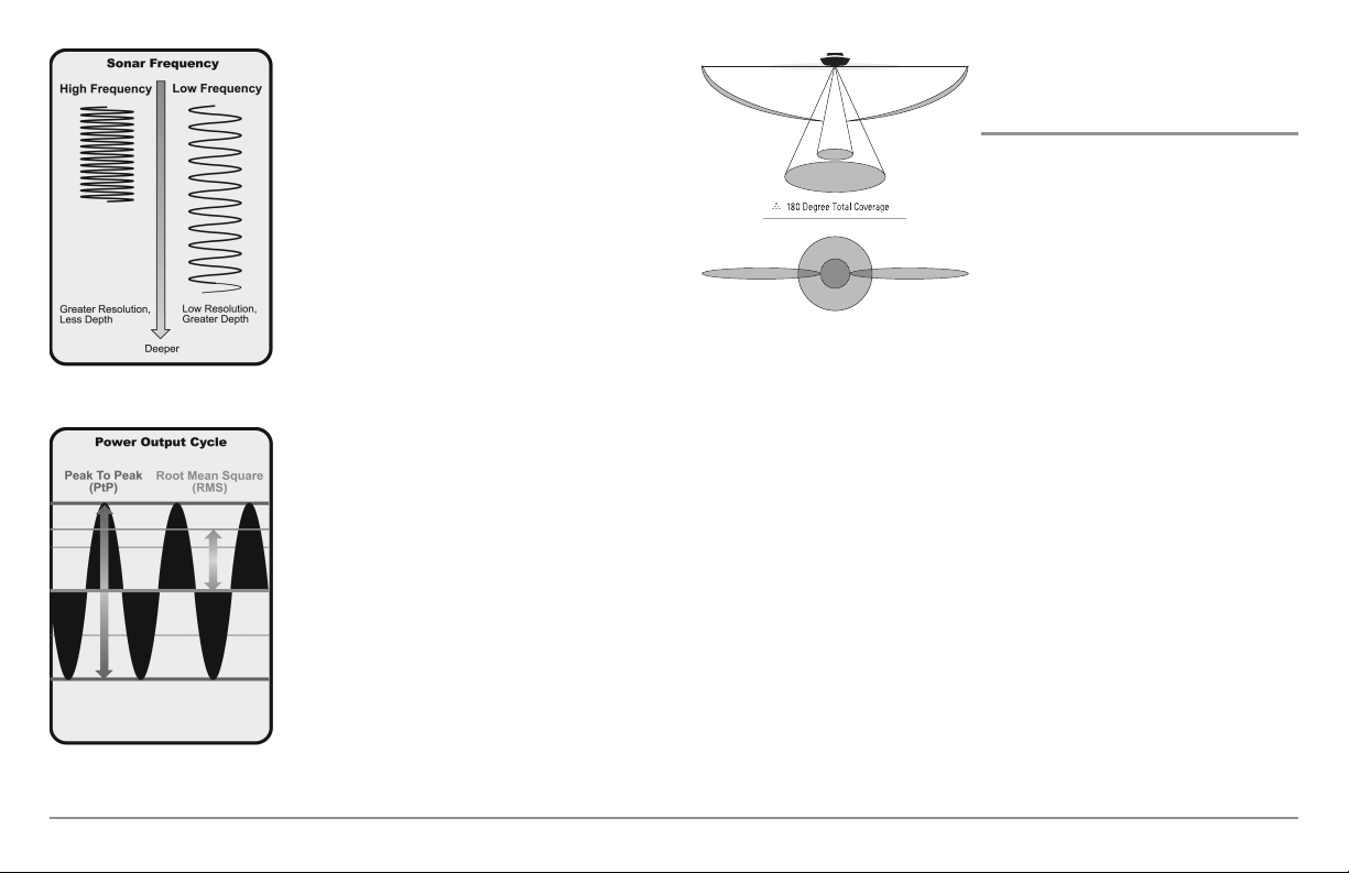
DualBeam PLUS™ Sonar
90° Total Coverage
Bottom Coverage=2 x Depth
35° 60° 20° 35°
455 kHz 455 kHz
83 kHz
200 kHz
(858c, 898c SI, 958c, 998c SI)
The Fishing System uses a 200/83 kHz
DualBeam PLUS™ sonar system with a wide
(60°) area of coverage. DualBeam PLUS™
sonar has a narrowly focused 20° center
beam, surrounded by a second beam of 60°,
expanding your coverage to an area equal to
your depth. In 20 feet of water, the wider
beam covers an area 20 feet wide.
DualBeam PLUS™ sonar returns can be
blended together, viewed separately, or
compared side-by-side. DualBeam PLUS™ is
ideal for a wide range of conditions - from
shallow to very deep water in both fresh and
salt water. Depth capability is affected by
such factors as boat speed, wave action,
bottom hardness, water conditions, and
transducer installation.
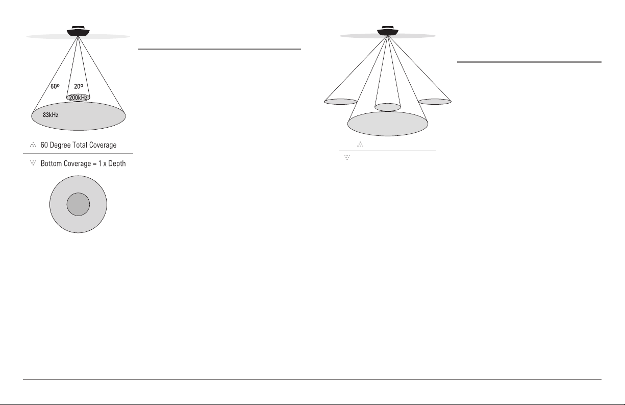
QuadraBeam PLUS™ Sonar
(optional-purchase QuadraBeam PLUS™
transducer only)
Your Fishing System supports the
optional-purchase QuadraBeam PLUS™
transducer. QuadraBeam PLUS™ sonar
provides a wide (90°) area of coverage.
QuadraBeam PLUS™ starts with two
fan-shaped 35° 455 kHz Side Structure
locating sonar beams to spot fish, bait,
and structure to the left and right of the
boat over an area of the bottom that’s
always equal to twice your depth.
For a detailed view below the boat,
QuadraBeam PLUS™ uses DualBeam
PLUS™ technology, with precision 20°
and wide 60° beams. QuadraBeam
PLUS™ finds more fish faster, and can
even tell you where to put your bait by
showing if fish are to the left, right, or
directly beneath your boat.
3
Introduction
Page 14

Universal Sonar 2
Your Fishing System supports Universal Sonar 2, a state-of-the-art,
integrated and protected transducer that is built into the lower unit of
Minnkota trolling motors. With Universal Sonar 2, all wiring is concealed
inside the indestructible composite shaft—out of sight and out of harm’s
way, with no clamps, ties, or exposed wires. Universal Sonar 2 features new
temperature sensing and the performance of DualBeam PLUS™ technology.
An expanded view and greater bottom detail gives you a totally new
perspective of the water below, along with optimal sonar performance to
help you find fish.
GPS was originally intended for military use; however, civilians may also take
advantage of its highly accurate position capabilities, typically within +/- 4.5
meters, depending on conditions. This means that 95% of the time, the GPS
receiver will read a location within 4.5 meters of your actual position. Your
GPS Receiver also uses information from WAAS (the Wide Area
Augmentation System), EGNOS (the European Geostationary Navigation
Overlay Service), and MSAS (the MTSAT Satellite Augmentation System)
satellites if they are available in your area.
The following GPS functionality is currently supported by the Fishing System
when it is connected to the included GPS receiver:
How GPS and Cartography Work
Your Fishing System also supports GPS (Global Positioning System) and
chartplotting. It uses GPS and sonar to determine your position, display it on
a grid, and provide detailed underwater information.
GPS uses a constellation of satellites that
continually send radio signals to the earth. The
GPS receiver on your boat receives signals from
satellites that are visible to it. Based on time
differences between each received signal, the
GPS receiver determines its distance to each
satellite. With distances known, the GPS
receiver mathematically triangulates its own
position. With once per second updates, the
GPS receiver then calculates its velocity and
bearing.
Introduction
• View current position
• View current track (breadcrumb trail)
• View precision speed and heading from your GPS receiver
• Save tracks, waypoints, and routes
• Travel a route and navigate from one waypoint to the next.
See Chart View and Introduction to Multi-Media Card (MMC)/SD Slots:
Add Maps to Your Fishing System for more information.
4
Page 15
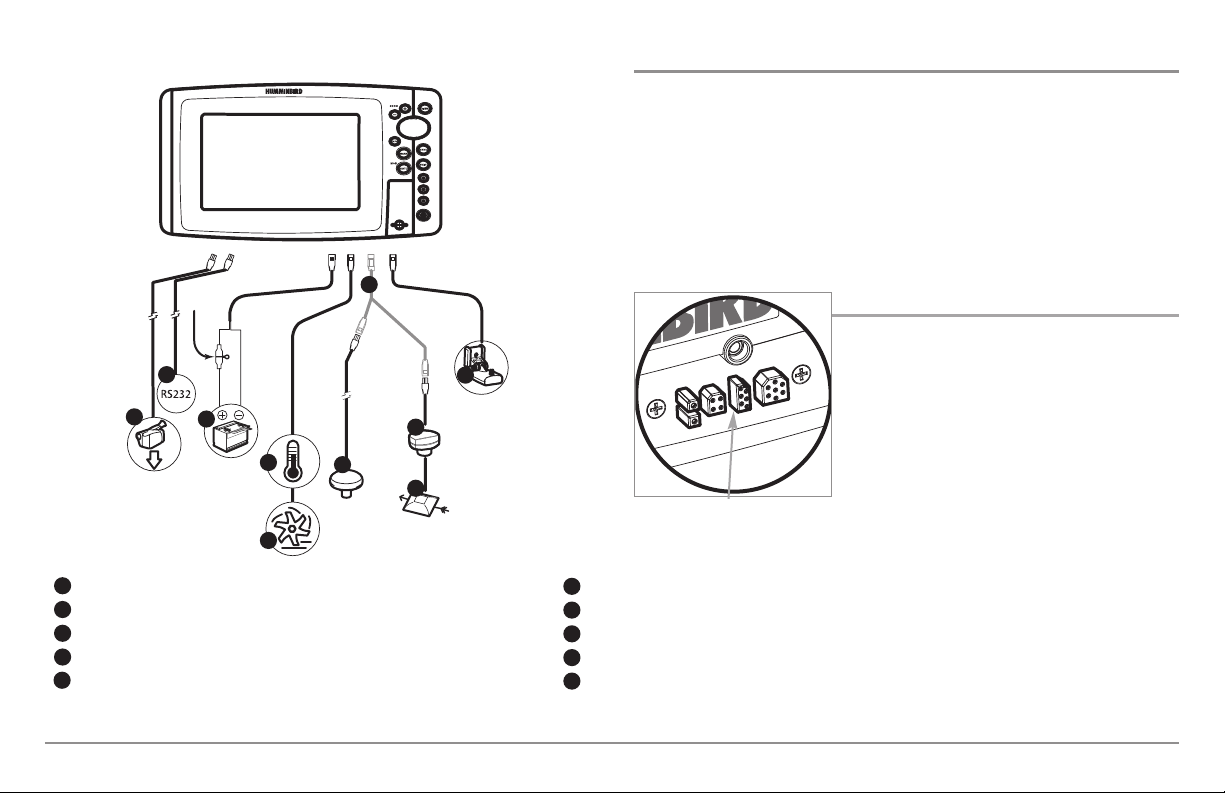
Video Out
1
RS 232 Connector
2
Power
3
Temperature
4
Speed
5
5
The Fishing System has a wide variety of configurations
6
2
1
3
4
5
7
8
9
SmartCast® Wireless Sonar Link
Sonar Transducer with Temperature
10
Optional “Y” Cable
GPS Receiver
WeatherSense®
Fishing System Configuration
The Fishing System has a wide variety of configurations that will influence the
installation. The accessory bus, video output, and RS 232 connectors allow you
to expand your Fishing System capabilities. As you expand the configuration,
the menu options that correspond with the connected accessory will be added
to the menu system.
Please read all instructions that are relevant for your configuration before
beginning the installation process.
Accessory Bus
Use the Accessory Bus to expand the
functionality of your Fishing System.
Accessories plug directly into the Fishing
System and enable advanced features such as
WeatherSense®, SmartCast®, and the AS WX 1
Satellite Weather Receiver.
Accessory Bus
6
7
8
9
10
NOTE: Accessories to enable WeatherSense®, SmartCast®, and the AS WX 1
Satellite Weather Receiver require separate purchases. Visit our web site at
humminbird.com or contact our Customer Resource Center at 1-800-633-1468
for details.
5
When an accessory is plugged into the Fishing
System, additional functions will be added
to the menu system automatically. See
Accessories Menu Tab and Fishing System
Accessories in this manual. Also, see the
accessory’s operations manual for additional
details.
Installation Introduction
Page 16
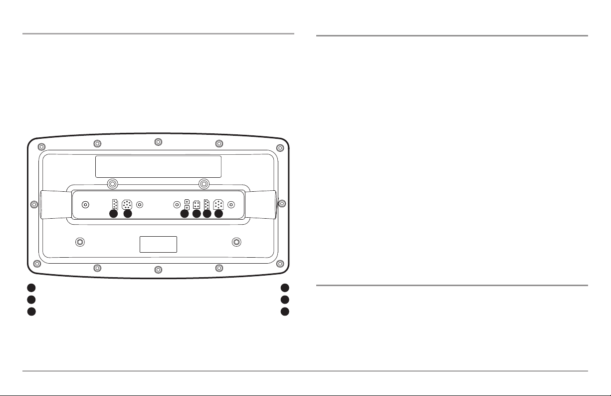
Video-Out and RS 232 Connectors
Your unit has a built-in Video Out connector and a dual RS 232 connector,
which can be used with optional-purchase equipment such as AIS
(Automatic Identification System). If you purchase a video monitor and
attach it to your control head using the Video Out connector, your unit will
send a video signal if it detects a monitor. See Setup Menu Tab: Video Out
for more information.
1 5 6
32 4
Installation Overview
Inside the boat there is often a channel or conduit used for other wiring, this
can be used to route cables. Be sure to route the cable as far as practical
from the antenna cable of VHF radios or tachometer cables to reduce the
possibility of interference. The transducer and GPS receiver cables should
not be cut, and care should be used not to damage the cable insulation.
Basic installation tasks that you must perform include:
• Installing the control head (choose gimbal or in-dash mounting,
where in-dash mounting requires a separate purchase)
• Installing the transducer (choose the installation method that
matches your transducer)
• Installing the GPS Receiver (if included)
• Testing the complete installation and locking the transducer position
NOTE: Accessories may require a separate purchase. You can visit our web site
at humminbird.com to order these accessories online or contact our Customer
Resource Center at 1-800-633-1468.
RS 232
1
Video Output
2
Power
3
NOTE: Accessories connected to the RS 232 or Video-Out connectors require a
separate power source.
Installation Introduction
Temp/Speed
Communications/GPS
Transducer
4
5
6
You have two choices for mounting your control head, Gimbal mounting,
where you use a surface on the boat, such as the dash, to mount the control
head so that it canbe tilted up or down, or In-dash mounting, which requires
a separate purchase.
6
Control Head Installation
Page 17

Gimbal Mounting the Control Head
If you are gimbal mounting the Humminbird®, you can pre-assemble the unit
in order to plan the best mounting location.
2. Place a 1" (25 mm) diameter black washer on the gimbal knob and
then thread the knob and washer into the housing. Tighten the
gimbal knob to secure the control head to the mount. Repeat step 2
for the other side.
1
2
3
Washer
1
Gimbal Knob
2
Gimbal Bracket
3
In addition to the hardware supplied with your control head, you will need a
powered hand drill and various drill bits, various hand tools, including a Phillips
head screwdriver, a socket wrench and a flat head screwdriver, a marker or
pencil, safety glasses and dust mask, and marine-grade silicone sealant.
1. Place the control head into the gimbal bracket. Make sure that the
straight side of the gimbal arm is against the back side of the control
head.
You can now place the control head in various locations to decide which is
best for mounting. Rotating the mounting bracket to the top of the control
head will allow for overhead mounting. The chosen mounting area should
allow for sufficient room so the control head can pivot through the full tilt
range and allow for easy removal and installation.
NOTE: You can drill the cable pass hole underneath the gimbal bracket, allowing
you to thread the cables through the knock-out holes in the mount; however, if
you cannot drill the hole directly under the mounting bracket, then you will need
to drill the cable pass hole behind the bracket, and will need to mount the hole
cover there instead.
NOTE: When drilling holes in fiberglass hulls, it is best to start with a smaller bit
and use progressively larger drill bits to reduce the chance of chipping or flaking
the outer coating. Fill all holes with marine grade silicone sealant.
NOTE: You must have underside access to the mounting location to pass the
cables through to the surface. Also, make sure that the mounting surface is
adequately supported to protect the control head from excessive wave shock and
vibration and provide visibility while in operation.
3. After the mounting location has been determined, loosen the gimbal
knobs and remove the control head from the gimbal bracket.
7
Installation - Gimbal Mount
Page 18
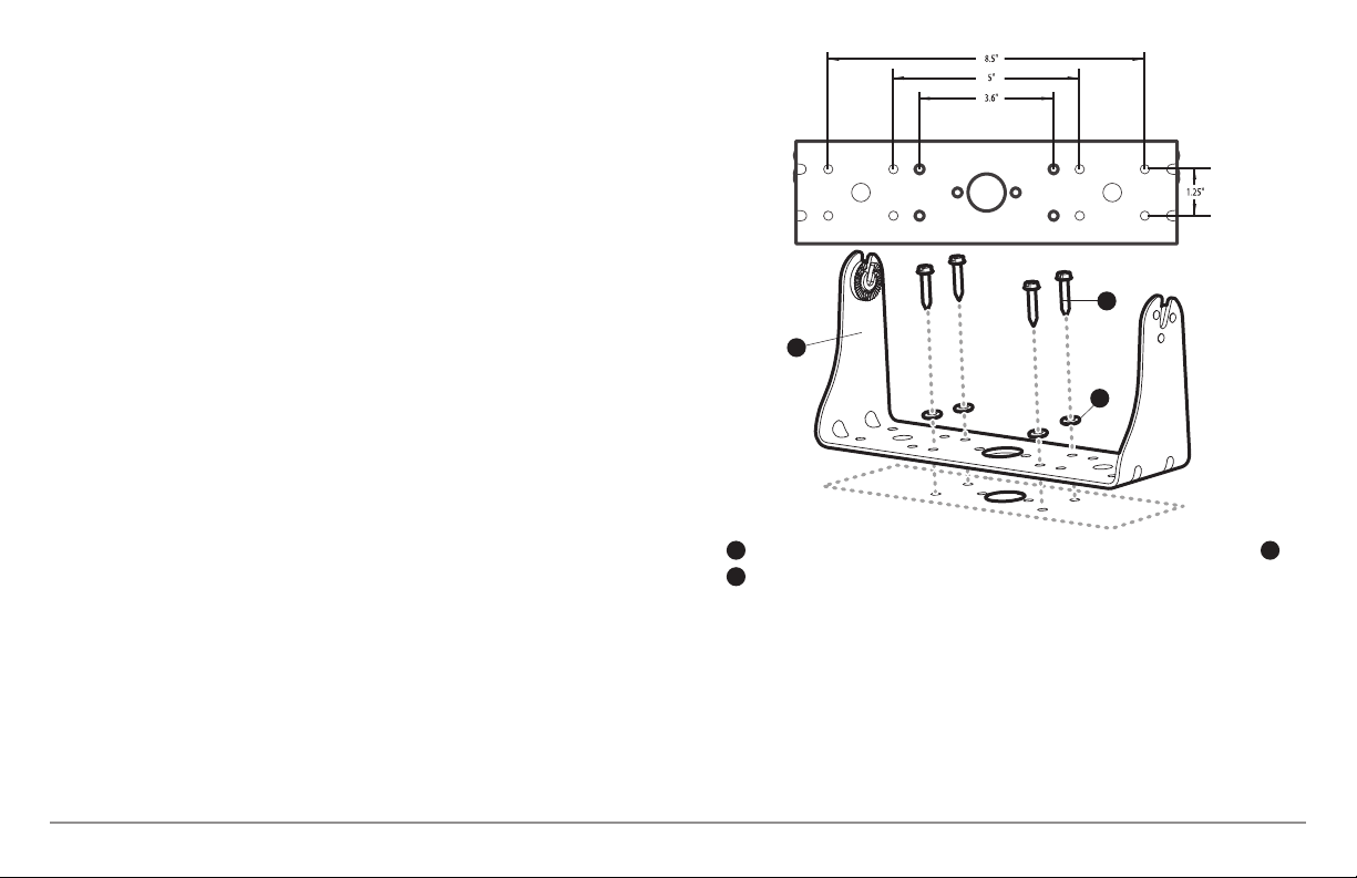
NOTE: Alternate hole patterns are available on the gimbal mounting bracket, and
may match existing holes on the boat. You may choose to use one of these
alternate hole patterns.
4. Place the gimbal bracket in the chosen position on the mounting
surface and mark the four mounting screw locations using a pencil
or center punch.
NOTE: Go to the installation instructions applicable to your transducer, GPS
Receiver and accessories. Make the required installations and then run the
cables to your control head mounting location. Do not cut any cabling (except the
power cable). If your cables are too short, extensions are available from your local
dealer or online from humminbird.com.
1
3
2
Installation - Gimbal Mount
Mounting Screws
1
Washer
2
Gimbal Mounting Bracket
5. Set the gimbal bracket aside and drill the four mounting screw holes
using a 5/32" (4.0 mm) drill bit.
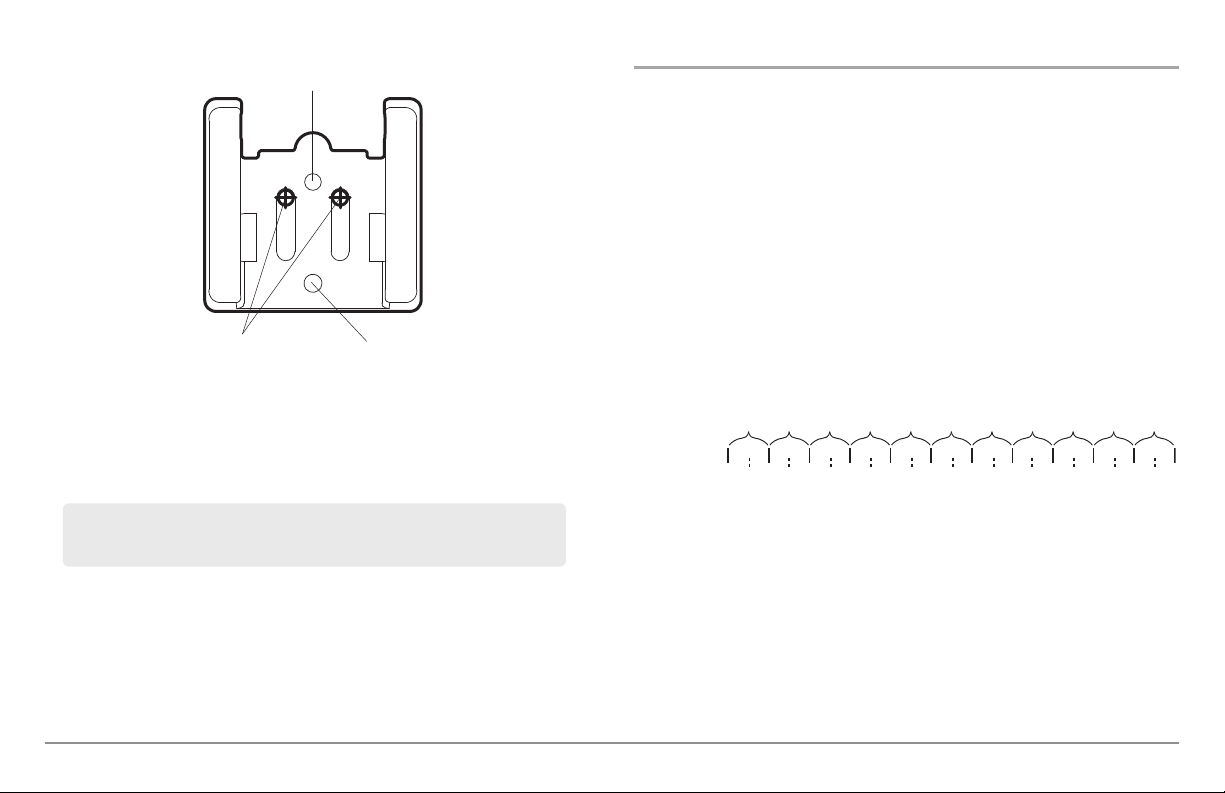
6a. If the cables must pass through a hole directly beneath the
mounting bracket, mark and drill an additional 1" (25 mm) hole
centered between the four mounting holes. Route the cables
through the 1" hole. Place the hole cover over the mounting surface
hole, then use it to mark the position of the two mounting screws.
8
3
Page 19
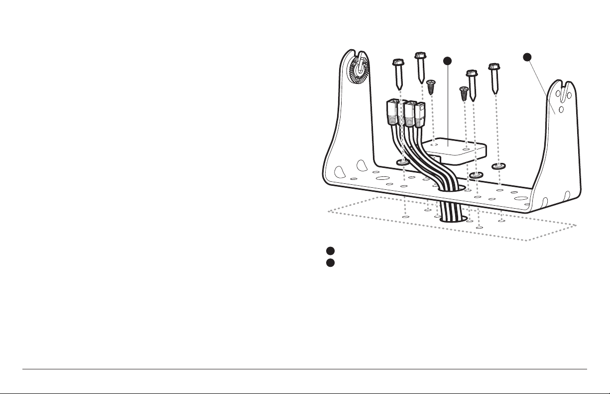
Remove the hole cover, drill the two mounting holes using a 9/64"
bit. Do not install the hole cover at this time.
Cables Routed Directly Beneath Mounting Bracket
6b. If the cables cannot be routed directly beneath the mounting
bracket, mark and drill a 1" (25 mm) hole that will allow you to run
the cables close to the bracket. Pass the cables through the 1" (25
mm) hole, routing the cables through the grommet and pressing the
grommet into place. Place the hole cover over the mounting surface
hole, then use it to mark the position of the two mounting screws.
Remove the hole cover, drill the two mounting holes using a 9/64"
(3.5 mm) bit, fill them with marine-grade silicone, then replace the
hole cover and insert the #8 Phillips countersink wood screws.
Hand-tighten only.
7. Place the mounting bracket on the mounting surface aligned with
the drilled holes and fill the mounting holes with marine grade
silicone. Insert the four #10 Slotted-Hex wood screws into the
mounting holes. Hand-tighten only.
8. If the cable pass through-hole is beneath the mounting bracket, you
will need to install the hole cover. Place the hole cover over the
mounting bracket cable pass through-hole and align with holes
drilled in step 6a. Insert the #8 Phillips countersink wood screws.
Hand tighten only.
NOTE: Be sure that the cables pass through the slots on the hole cover and that
there is enough cable slack to allow for the control head to pivot through its full tilt
range. Extra cable slack will also help when connecting/disconnecting the cables.
Gimbal Bracket
1
Hole Cover
2
2
1
9
Installation - Gimbal Mount
Page 20
Cables Routed Behind Mounting Bracket
1 2
3 4
1
Power
1
Temp/Speed
3
2
Communications/GPS
3
Transducer
4
Cable Collector Insert
5
5
2
Gimbal Bracket
1
Grommet
2
Hole Cover
3
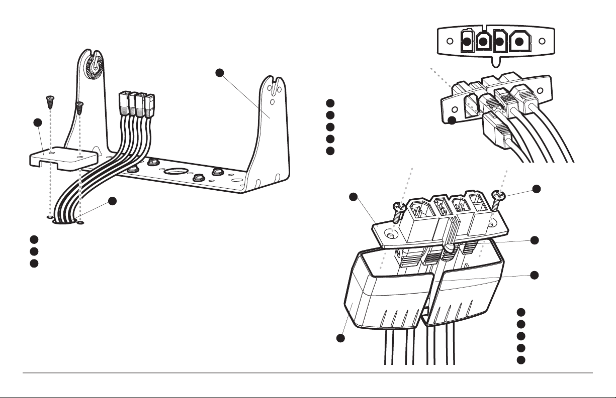
9. Insert cable connectors into the proper recesses on the cable
collector insert. The cable connectors are keyed to prevent reverse
installation, so be careful not to force the connectors into the wrong
slots. If you don’t have a cable for every hole in the insert, install the
blank plugs to protect the control head from the weather.
Installation - Gimbal Mount
1
2
4
5
Cable Collector Insert
1
Screws
2
Cable Collector Cover
3
3
Tab on Insert
4
Slot on Cover
5
10
Page 21
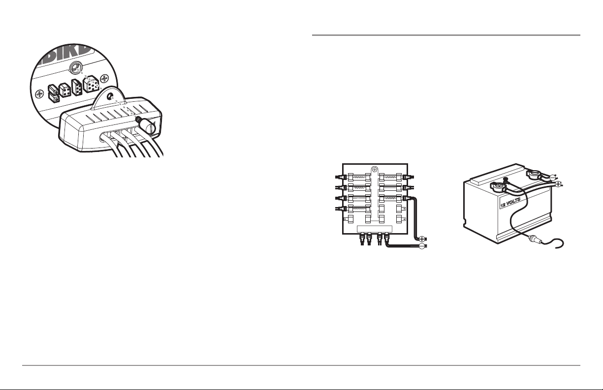
Plug Cable Connector Assembly to
GROUNDGROUND
POSITIVEPOSITIVE
Back of Control Head
10. While holding cables in place
in the cable collector insert,
thread the cables through
the slot in the bottom of the
cable collector cover, line up
the cable collector insert and
cover, then slide the cover
into place on the insert.
NOTE: The tab on the Cable Collector
insert goes into the slot on the cover.
11. Attach the cable collector insert to the cable collector cover using
the 2 Phillips screws provided.
12. Place the control head back onto the mounting bracket. Plug in the
cable collector assembly to the back of the control head. Cable
connectors and cable sockets are keyed to prevent reverse
installation, so be careful not to force the connectors into the wrong
sockets. Once the cable collector and all cables are plugged into the
back of the control head, lock the assembly into place by threading
the knurled screw into the threaded insert on the back of the
housing. Adjust the control head to the desired viewing angle and
secure by tightening the gimbal knobs.
NOTE: You may wish to dress the cabling with nylon wire ties in order to hold the
cables together and create a cleaner assembly.
The Humminbird® control head is now ready for operation.
Connecting the Control Head Power Cable to the Boat
A 6' (2 m) long power cable is included to supply power to the control head.
You may shorten or lengthen the cable using 18 gauge multi-stranded
copper wire.
CAUTION: Some boats have 24 or 36 Volt electric systems, but the control head
MUST be connected to a 12 VDC power supply.
The control head power cable can be connected to the electrical system of
the boat at one of two places: a fuse panel usually located near the console,
or directly to the battery.
NOTE: Make sure that the power cable is disconnected from the control head at
the beginning of this procedure.
NOTE: Humminbird® is not responsible for over-voltage or over-current failures.
The control head must have adequate protection through the proper selection
and installation of a 3 amp fuse.
11
Installation - Power
Page 22

1a. If a fuse terminal is available, use crimp-on type electrical
connectors (not included) that match the terminal on the fuse
panel. Attach the black wire to ground (-), and the red wire to
positive (+) 12 VDC power. Install a 3 amp fuse (not included) for
protection of the unit. Humminbird® is not responsible for overvoltage of over-current failures.
or...
1b. If you need to wire the control head directly to a battery, obtain
and install an inline fuse holder and a 3 amp fuse (not included)
for the protection of the unit. Humminbird® is not responsible for
overvoltage or over-current failures.
NOTE: In order to minimize the potential for interference with other marine
electronics, a separate power source (such as a second battery) may be
necessary.
You are now ready to install the transducer. Find the section that refers to
your specific transducer installation method.
Transducer Installation Overview
Proceed to the installation section that matches your transducer type. Your
choices are as follows:
• 858c, 958c: DualBeam PLUS™ (XNT 9 20 T), Transom Mount
• 858c, 958c: DualBeam PLUS™ (XNT 9 20 T), Inside the Hull Mount
• 898c SI, 998c SI: Side Imaging® (XHS 9 HDSI 180T), Transom Mount
• All units: Trolling Motor Transducer Installation
NOTE: Due to the wide variety of hulls, only general instructions are presented
in this installation guide. Each boat hull represents a unique set of requirements
that should be evaluated prior to installation. It is important to read the
instructions completely and understand the mounting guidelines before
beginning installation.
If the included transducer will not work for your application, you may
NOTE:
exchange it, NEW and UNASSEMBLED, with mounting hardware included, for
a transducer appropriate for your application - often at very little or no charge
depending on the transducer. Call the Humminbird® Customer Resource
Center at 1-800-633-1468 for details and pricing, or visit humminbird.com.
Installation - Power
12
Page 23

858c & 958c Transom Mount Transducer Installation
DualBeam PLUS™ Transducer, XNT 9 20 T (858c and 958c only)
The DualBeam PLUS™ transducer uses a Two Piece Kick-up transducer
mounting bracket.
NOTE: Due to the wide variety of hulls, only general instructions are presented in
this installation guide. Each boat hull represents a unique set of requirements that
should be evaluated prior to installation. It is important to read the instructions
completely and understand the mounting guidelines before beginning
installation.
NOTE: Your transducer may not look exactly like the transducer shown in the
illustrations, but it will mount in exactly the same way.
Overview
If you will be installing a DualBeam PLUS™ transom mounted transducer, use
the procedures in this section. There are several procedures you will have to
perform in order to install a transom-mounted transducer. They are as
follows:
• Locate the transducer mounting location
• Prepare the mounting location
• Assemble the transducer and perform initial mounting
• Route the transducer cable
• Connect the transducer cable
• Perform a final test of the transom transducer installation.
In addition to the hardware supplied with your transducer, you will need a
powered hand drill and various drill bits, various hand tools, including a ruler
or straightedge, a level, a 12" plumb line (weighted string or monofilament
line), marker or pencil, safety glasses and dust mask, and marine-grade
silicone sealant.
NOTE: When drilling holes in fiberglass hulls, it is best to start with a smaller bit
and use progressively larger drill bits to reduce the chance of chipping or flaking
the outer coating.
13
Transom Mount - DualBeam PLUS™
Page 24
1. Locating the transducer mounting location
15”
NOTE: If transom mounting is not possible because of a stepped hull or
cavitation noise, and you have a single layer fiberglass hull, In-hull installation is
an option. See Inside the Hull Transducer Installation for more information.
Turbulence: You must first determine the best location on the transom to
install the transducer. It is very important to locate the transducer in an area
that is relatively free of turbulent water. Consider the following to find the
best location with the least amount of turbulence:
• As the boat moves through the water, turbulence is generated by the
weight of the boat and the thrust of the propeller(s) - either clockwise
or counter-clockwise. This turbulent water is normally confined to areas
immediately aft of ribs, strakes or rows of rivets on the bottom of the
boat, and in the immediate area of the propeller(s). Clockwise
propellers create more turbulence on the port side. On outboard or
inboard/outboard boats, it is best to locate the transducer at least 15"
to the side of the propeller(s).
Areas of Possible Turbulence
Rivets Strakes
Transom Hull
Transom Mount - DualBeam PLUS™
Step Rib
Stepped Hull
• The best way to locate turbulence-free water is to view the transom
while the boat is moving. This method is recommended if maximum
high-speed operation is a high priority. If this is not possible, select a
location on the transom where the hull forward of this location is
smooth, flat and free of protrusions or ribs.
Level
Find a turbulence-free location at least 15" from the propeller(s)
and not in line with trailer bunks or rollers.
Deadrise Angle
• On boats with stepped hulls, it may be possible to mount the
transducer on the step. Do not mount the transducer on the transom
behind a step to avoid popping the transducer out of the water at
higher speeds; the transducer must remain in the water for the
control head to maintain the sonar signal.
14
Page 25
• If the transom is behind the propeller(s), it may be impossible to find
an area clear from turbulence, and a different mounting technique or
transducer type should be considered, such as an Inside the Hull
Transducer (see Inside the Hull Transducer Installation).
• If you plan to trailer your boat, do not mount the transducer too close
to trailer bunks or rollers to avoid moving or damaging the transducer
during loading and unloading of the boat.
• If high speed operation is critical, you may want to consider using an
In-Hull transducer instead of this Transom Mount transducer.
protrude past the bottom of the hull, and there is at least 1/4"
clearance between the bottom of the bracket and the bottom of the
transom for fiberglass boats, and 1/8" clearance for aluminum
boats.
Positioning the
Mounting Bracket
Level
Boat Hull Types Require
Different Mounting Positions
NOTE: The hydrodynamicshape of your transducer allows it to point straight down
without deadrise adjustment.
NOTE: If you cannot find a transom mount location that will work for your highspeed application, find an In-Hull Transducer by contacting our Customer Resource
Center at either 1-800-633-1468 or by visiting our web site at humminbird.com.
2. Preparing the Mounting Location
In this procedure, you will determine the mounting location and drill two
mounting holes, using the transducer mounting bracket as a guide.
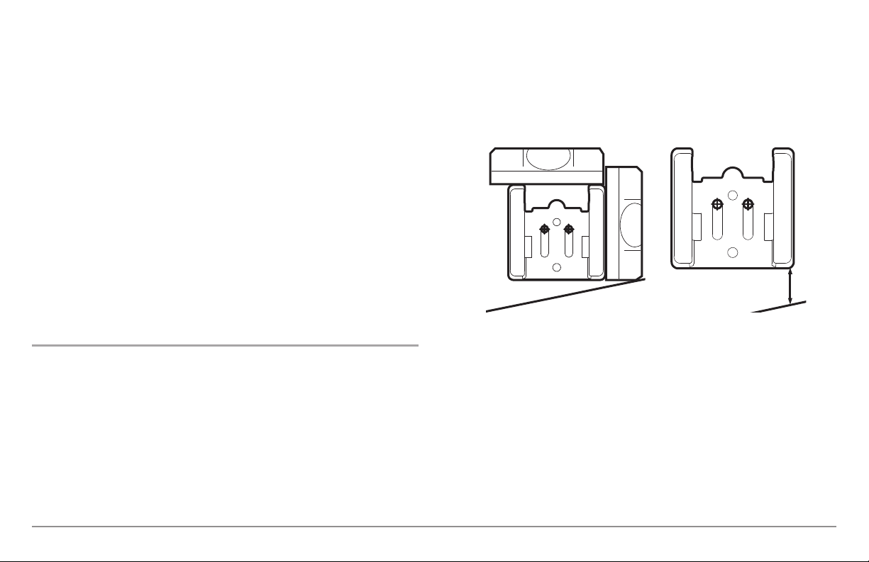
1. Make sure that the boat is level on the trailer, both from port to
starboard and from bow to stern, by placing your level on the deck of
the boat, first in one direction, then in the other.
2. Hold the mounting bracket against the transom of the boat in the
location you have selected. Align the bracket horizontally, using the
level; make sure that the lower corner of the bracket does not
Level
1/4” for fiberglass
1/8” for aluminum
NOTE: If you have a flat-bottomed aluminum boat, some additional adjustment
may be needed to accommodate the rivets on the bottom of the boat (i.e. the gap
may need to be a little smaller than 1/8"). This will help you to avoid excessive
turbulence at high speeds.
NOTE: If your propeller moves clockwise (in forward, as you're facing the stern of
the boat from behind), mount the transducer on the starboard side, and align the
bottom right corner of the mounting bracket with the bottom of the boat. If your
propeller moves counter-clockwise (in forward, as you're facing the stern of the
boat from behind), mount the transducer on the port side, and align the bottom
left corner of the mounting bracket with the bottom of the boat.
15
Transom Mount - DualBeam PLUS™
Page 26
-2 -1 0 1 2 3 4 5 6 7 8 9 10 11 12 13 14 15 16 17 18 19 20 21 22 23 24
Transom Angle (°)
Bead Alignment
Number
142531425
25 26 27328 29 30
1
Measured Distance (x)
1.1cm
1/2“
0.0 cm
0“
2.5 cm1“4.3 cm
1 5/8“
5.9 cm
2 3/8“
7.6 cm3“9.3cm
3 5/8“
11.1cm
4 3/8“
12.9cm5“14.9cm
5 7/8“
16.9cm
6 5/8“
Using the Mounting Bracket to Mark the Initial Drill Holes
Fourth Hole
Mark Initial Drill Holes
Third Hole
3. Continue to hold the bracket on the transom of the boat, and use a
pencil or marker to mark where to drill the two mounting holes.
Mark the drill holes near the top of each slot, making sure that your
mark is centered in the slot.
3. Assembling the Transducer and Initial Mounting
In this procedure, you will assemble the transducer using the hardware
provided, then mount it and make adjustments to its position without locking
it in place.
NOTE: You will initially assemble the transducer and the pivot arm by matching
the two ratchets to a numbered position on the transducer knuckle. Further
adjustments may be necessary.
1a. If you already know your transom angle, refer to the chart below for
the initial position to use to set the ratchets. If your transom is
angled at 14 degrees (a common transom angle for many boats) use
position 1 for the ratchets. In either case, go to step 2.
or...
NOTE: The third hole should not be drilled until the angle and height of the
transducer is finalized, which you will not do until a later procedure.
4. Make sure that the drill bit is perpendicular to the actual surface of
the transom, NOT parallel to the ground, before you drill. Using a
5/32” bit, drill the two holes only to a depth of approximately 1”.
NOTE: On fiberglass hulls, it is best to use progressively larger drill bits to reduce
the chance of chipping or flaking the outer coating.
Transom Mount - DualBeam PLUS™
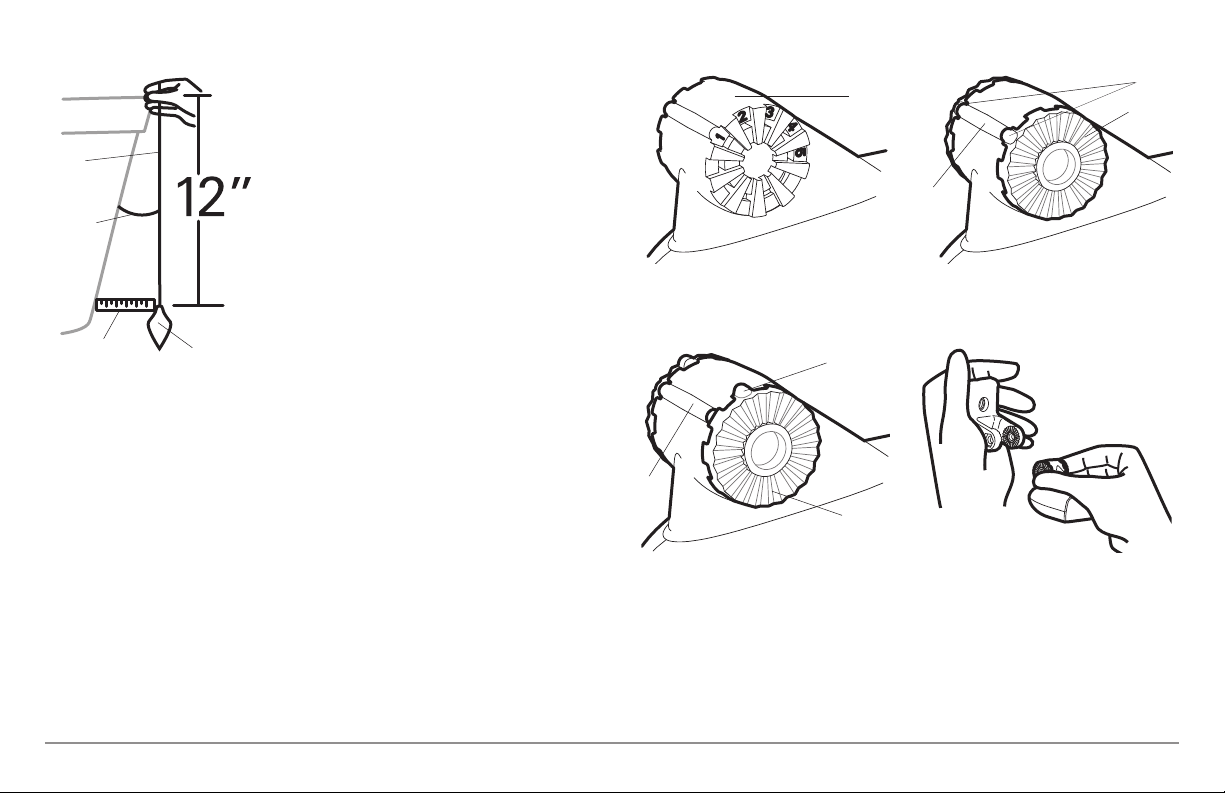
1b. If you do not know your transom angle, measure it using a plumb
line (weighted nylon string or monofilament line) exactly 12 inches
long. Hold the top of the plumb line against the top of the transom
with your finger, and wait until the line hangs straight down. Using
a ruler, measure the distance from the bottom of the plumb line to
the back of the transom, then use the chart.
16
Page 27
Measuring the Transom Angle
NOTE: It is important to take your measurement in
the figure showing Measuring the Transom
Angle, from exactly 12 inches down from the top
of the transom.
Transducer Knuckle Positions
Knuckle
Ratchets Placed in Position 1
Beads
Ratchet
Plumb
line
Transom
Angle in
degrees
(°)
2. Place the two ratchets, one on either
side of the transducer knuckle, so that
the beads on each ratchet line up with
the desired position number on the
knuckle. If you are setting the ratchets
at position 1, the beads on each ratchet
will line up with the rib on the
Measured
Distance (X)
Weight
transducer knuckle to form one
continuous line on the assembly.
NOTE: The ratchets are keyed; make sure that
the square teeth on each ratchet face the
square teeth on the transducer knuckle, and
the triangular teeth face outward.
Hold the ratchets on the transducer knuckle with one hand and fit
the pivot arm over them until it snaps into place with the other
hand. Refer to the illustration.
Rib at
position 1
Ratchets Placed in Position 2 Fitting the Pivot Arm Over the Ratchet
Bead
Rib
Ratchet
17
Transom Mount - DualBeam PLUS™
Page 28
Inserting the Pivot Bolt
Inserting the Pivot Arm Assembly into
the Mounting Bracket
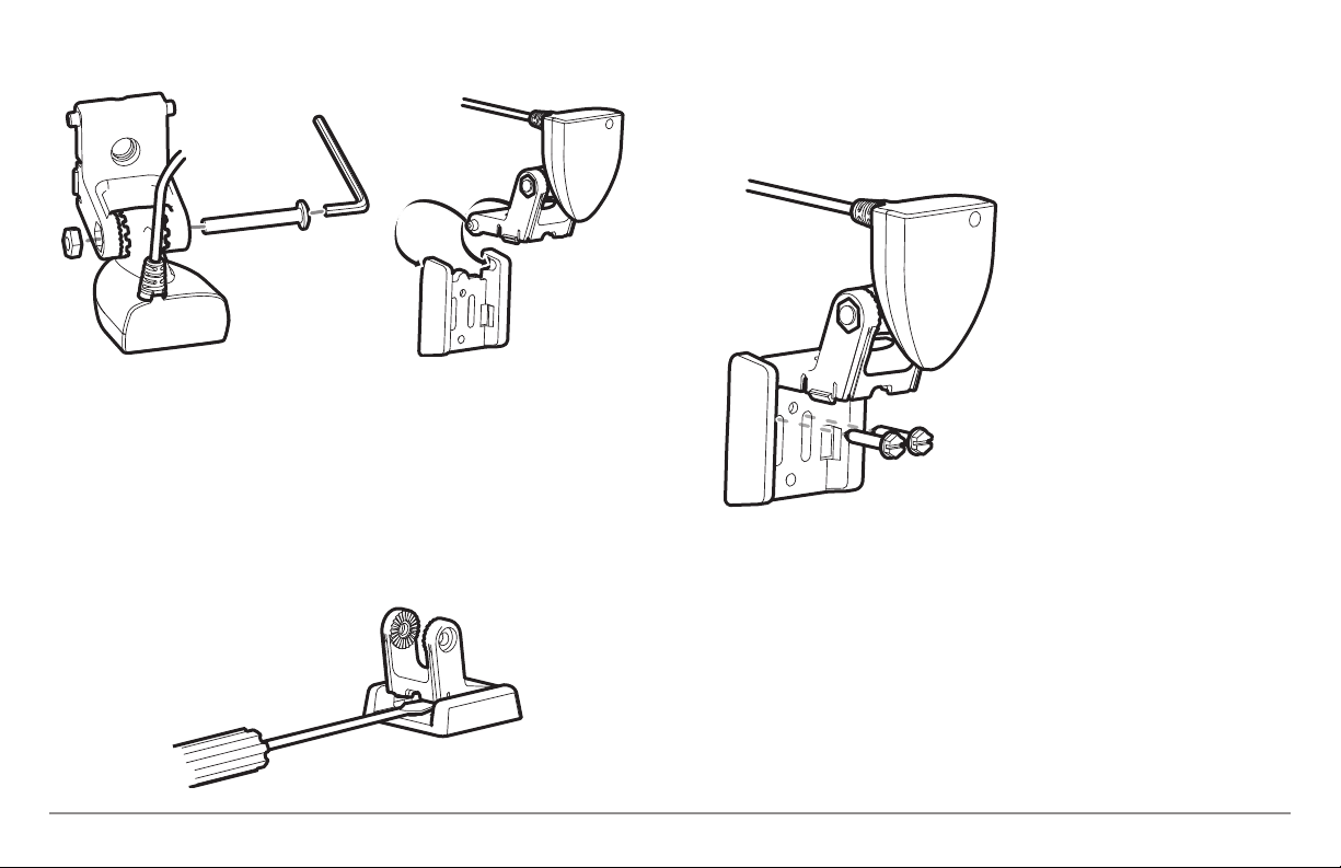
4. Align the mounting bracket transducer assembly with the drilled
holes in the transom. With a 5/16" socket driver, mount the assembly
to the transom using the two #10 - 1" long screws provided.
3. Put the pivot bolt through the assembly to hold it in position and
loosely install the nut, but do NOT tighten the nut at this time. Insert
the pivot arm assembly into the mounting bracket. Do NOT snap the
assembly closed, as you will need to access the mounting bracket in
the next step.
NOTE: If the pivot assembly is snapped closed over the mounting bracket, use a
flat head screwdriver or similar tool to gently pry the assembly away from the
mounting bracket.
Mounting the Assembly to the Transom
NOTE: Make sure that the mounting
screws are snug, but do not fully
tighten the mounting screws at this
time to allow the transducer
assembly to slide for adjustment
purposes.
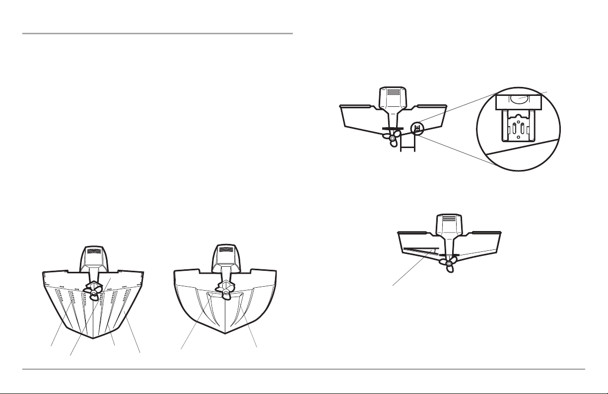
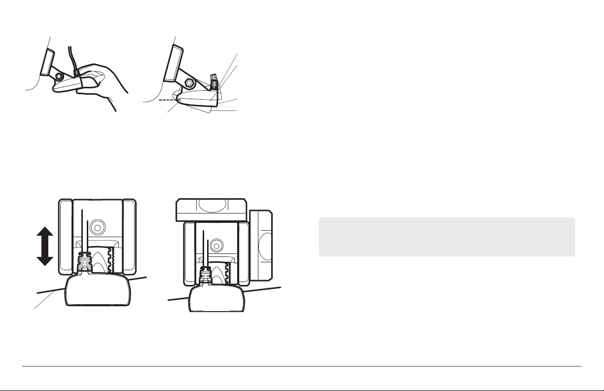
5. Snap the pivot arm down
into place.
6. Adjust the initial angle of the
transducer from back to front
by rotating the transducer
until the side seam on the
transducer is almost parallel
with the bottom of the boat,
one click at a time in either
direction.
Transom Mount - DualBeam PLUS™
18
Page 29
Adjusting the Initial Transducer Angle
One click too high
Correctly aligned
(transducer side
seam aligned with
boat bottom)
Trailing edge
Leading edge
One click too low
7. Adjust the transducer assembly vertically, until the seam on the
leading edge of the transducer (the edge closest to the transom of
the boat) is level and just slightly below the hull.
Adjusting the Transducer
Mounting Position
Leveling the Mounting
Assembly Horizontally
Level
Level
NOTE: The transducer has a natural downward slant of 4-5 degrees from leading
edge (closest to the boat transom) to trailing edge (farthest away from the boat).
Looking at the back of the transducer, the seam should be slightly below the
bottom of the hull.
8. Continue to adjust until the bracket is also level from port to
starboard (horizontally level as you look at the transducer from
behind the boat).
9. Mark the correct position on the transom by tracing the silhouette
of the transducer mounting bracket with a pencil or marker.
10. Tighten the pivot bolt, using the pivot screw and nut to lock the
assembly. Hand tighten only!
11. Snap open the assembly and hand-tighten the two mounting
screws, then snap the assembly closed.
NOTE:
You will drill the third mounting hole and finalize the installation after
you route the cable and test and finish the installation in the following
procedures.
Seam aligned with boat hull
19
Transom Mount - DualBeam PLUS™
Page 30

4. Routing the Cable
The transducer cable has a low profile connector, which must be routed to
the point where the control head is mounted. There are several ways to route
the transducer cable to the area where the control head is installed. The
most common procedure routes the cable through the transom into the boat.
NOTE: Your boat may have a pre-existing wiring channel or conduit that you can
use for the transducer cable.
1. Unplug the other end of the transducer cable from the control head.
Make sure that the cable is long enough to accommodate the
planned route by running the cable over the transom.
CAUTION! Do not cut or shorten the transducer cable, and try not to damage the
cable insulation. Route the cable as far as possible from any VHF radio antenna
cables or tachometer cables to reduce the possibility of interference. If the cable
is too short, extension cables are available to extend the transducer cable up to
a total of 50'. For assistance, contact the Customer Resource Center at
humminbird.com or call 1-800-633-1468 for more information.
NOTE: The transducer can pivot up to 90 degrees in the bracket. Allow enough
slack in the cable for this movement. It is best to route the cable to the side of
the transducer so the transducer will not damage the cable during movement.
2a. If you are routing the cable over the transom of the boat, secure the
cable by attaching the cable clamp to the transom, drilling 9/64"
diameter holes for #8 x 5/8" wood screws, then skip directly to
procedure 5, Connecting the Cable.
Routing the Cable
2b. If you will be routing the cable
through a hole in the transom, drill a
5/8" diameter hole above the
waterline. Route the cable through
this hole, then fill the hole with
marine-grade silicone sealant and
proceed to the next step
immediately.
3. Place the escutcheon plate over the
cable hole and use it as a guide to
mark the two escutcheon plate
mounting holes. Remove the plate,
drill two 9/64" diameter x 5/8" deep
holes, and then fill both holes with
marine-grade silicone sealant. Place
the escutcheon plate over the cable
hole and attach with two #8 x 5/8"
wood screws.
4. Route and secure the cable by attaching the cable clamp to the
transom; drill one 9/64" diameter x 5/8" deep hole, then fill the hole
with marine-grade silicone sealant, then attach the cable clamp
using a #8 x 5/8" screw.
5. Plug the other end of the transducer cable back into the control
head connection holder.
Transom Mount - DualBeam PLUS™
or...
20
Page 31

Storing Excess Cable
NOTE: If there is excess cable that needs to
be gathered at one location (as shown in
the illustration), dress the cable routed from
both directions so that a single loop is left
extending from the storage location.
Doubling the cable up from this point, form
the cable into a coil. Storing excess cable
using this method can reduce electronic
interference.
5. Connecting the Cable
Insert the transducer cable into the appropriate terminal slot. The cable
connectors are labeled, and there are corresponding labels on the cable
holder on the rear of the control head. The slots are keyed to prevent
reversed installation, so be careful not to force the connector into the holder.
Refer to your manual and/or control head installation guide for the correct
procedure for installing the cable connectors to the control head.
1. Plug the other end of the transducer cable back into the control
head connection holder.
Your control head is now ready for operation.
6. Test and Finish the Installation
Once you have installed both the control head and the transom transducer,
and have routed all the cables, you must perform a final test before locking
the transducer in place. Testing should be performed with the boat in the
water, although you can initially confirm basic operation with the boat out
of the water.
1. Press POWER once to turn the control head on. If the unit does not
power up, make sure that the connector holder is fully seated in the
receptacle and that power is available.
2. If all connections are correct and power is available, the
Humminbird® control head will enter Normal operation.
3. If the bottom is visible on-screen with a digital depth readout, the
unit is working properly. Make sure that the boat is in water greater
than 2' but less than the depth capability of the unit, and that the
transducer is fully submerged, since the sonar signal cannot pass
through air.
NOTE: The transducer must be submerged in water for reliable transducer
detection.
4. If the unit is working properly, gradually increase the boat speed to
test high-speed performance. If the unit functions well at low
speeds, but begins to skip or miss the bottom at higher speeds, the
transducer requires adjustment.
5. If you have the correct angle set on the transducer, yet lose a bottom
reading at high speed, adjust the height and the running angle in
small increments to give you the ideal transducer position for your
boat. First, adjust the height in small increment.
21
Transom Mount - DualBeam PLUS™
Page 32

NOTE: The deeper the transducer is in the water, the more likely that a rooster
tail of spray will be generated at high speeds, so make sure that the transducer
is as high as it can be and still be submerged in the water.
If you are still not getting good high speed readings, you may need
to disassemble the transducer mounting assembly and re-position
the ratchets.
If you do change the transducer position, re-trace the position of the
mounting bracket before proceeding.
NOTE: It is often necessary to make several incremental transducer adjustments
before optimum high speed performance is achieved. Due to the wide variety of
boat hulls, however, it is not always possible to obtain high speed depth
readings.
6. Once you have reached a consistently good sonar signal at the
desired speeds, you are ready to lock down the transducer settings.
Force the pivot to the Up position to gain access to the mounting
screws, then re-align the mounting bracket against the transom of
the boat to match the traced silhouette. Check the bracket position
with the level again to make sure it is still level, then mark the third
mounting hole using a pencil or marker. Unscrew and remove the
mounting screws and the transducer assembly and set aside.
7. Drill the third mounting hole, using a 5/32” drill bit. Use a marinegrade silicone sealant to fill all three drilled mounting holes,
especially if the holes penetrated the transom wall.
NOTE: On fiberglass hulls, it is best to use progressively larger drill bits to reduce
the chance of chipping or flaking the outer coating.
Fully Tighten All Three
Mounting Screws
8. Re-position the transducer assembly
against the transom of the boat, then
hand-install all three screws. Make
sure that the transducer location and
the pivot angle have not changed,
then fully tighten all three mounting
screws. Snap the pivot back down. If
you have performed the preceding
procedures correctly, the transducer
should be level and at the right
height for optimal operation.
Transom Mount - DualBeam PLUS™
22
Page 33

Locking Down the Transducer (Optional)
NOTE: You have the option to lock down the Two Piece Kick Up bracket if you do
not want the transducer to kick up. Please be aware, however, that the
transducer can be damaged if it is locked down and it strikes debris in the water.
Marking the Fourth Drill Hole
for Optional Lock Down
Fourth Hole
Mark Initial Drill Holes
Third Hole
2. Drill the fourth mounting hole, using a 9/64" drill bit. Use a marine
grade silicone sealant to fill all four drilled mounting holes,
especially if the holes penetrate the transom wall.
1. To lock down the transducer, trace
the position of the mounting
bracket. Force the pivot to the Up
position to gain access to the
mounting screws, then re-align the
mounting bracket against the
transom of the boat to match the
traced silhouette. Check the bracket
position with the level again to make
sure it is still level, then mark the
fourth mounting hole using a pencil
or marker. Unscrew and remove the
mounting screws and the transducer
assembly and set aside.
Fully Tighten All Three
Mounting Screws
3. Re-position the transducer assembly
against the transom of the boat, then
hand install the first three screws
(two on the outside edges and one in
the 3rd mounting hole). Make sure
that the transducer location and the
pivot angle have not changed, then
fully tighten all three mounting
screws. Hand tighten only!
4. Snap the pivot back down. Install
#8 x 1" wood screw into the 4th hole
to lock down the pivot arm. Handtighten only!
23
Transom Mount - DualBeam PLUS™
Page 34

858c & 958c Inside the Hull Transducer Installation
DualBeam PLUS™ Transducer, XNT 9 20 T (858c and 958c only)
NOTE: Your transducer may not look exactly like the transducer shown in the
illustrations, but it will mount in exactly the same way.
NOTE: Do NOT install the Side Imaging® transducer inside the hull, as the side
looking beams cannot penetrate the hull. Only the DualBeam PLUS™ transducer
can be mounted inside the hull.
If you choose to mount your transducer inside the hull of your boat, perform
the procedures in this section. In-hull mounting generally produces good
results in single thickness fiberglass-hulled boats. Humminbird® cannot
guarantee depth performance when transmitting and receiving through the
hull of the boat, since some signal loss occurs. The amount of loss depends
on hull construction and thickness, as well as the installation position and
process.
This installation requires slow-cure two-part epoxy. Do not use silicone
or any other soft adhesive to install the transducer, as this material
reduces the sensitivity of the unit. Do not use five-minute epoxy, as it has
a tendency to cure before all the air bubbles can be purged, thus
reducing signal strength.
NOTE: In-hull mounting requires an installed and operational control head.
NOTE: The integral temperature probe will not work with in-hull mounting, so
you may either want to consider purchasing a Temperature/Speed accessory, a
Temp. Sensor, or obtaining a different transducer. Humminbird® offers a
transducer exchange program to swap the NEW and UNASSEMBLED transducer,
accompanied by mounting hardware, for one without an integral temperature
probe. Call the Humminbird® Customer Resource Center at 1-800-633-1468 for
details, or visit humminbird.com for more information.
There are several procedures you will have to perform in order to install a
transducer inside the hull. They are as follows:
• Locate transducer mounting location
• Perform a trial installation
• Route the transducer cable
• Permanently mount the transducer
1. Locating the transducer mounting location
Decide where to install the transducer on the inside of the hull. Consider the
following to find the best location:
• Observe the outside of the boat hull to find the areas that are mostly
free from turbulent water. Avoid ribs, strakes and other protrusions,
as these create turbulence.
• As a general rule, the faster the boat can travel, the further aft and
closer to the centerline of the hull the transducer has to be located
in order to remain in contact with the water at high speeds.
Inside the Hull Mount - DualBeam PLUS™
24
Page 35

Areas of Possible Turbulence
Stepped Hull
3. Place the transducer body face down at the identified mounting
location inside the hull, with the end that has the mounting knuckle
pointed towards the bow of the boat.
Preferred Mounting Area
Rivets Strakes
Transom Hull
Step Rib
2. Trial installation
You will not be able to adjust the mounting after an inside the hull
transducer is installed. It is best, therefore, to perform a trial installation first
that includes running the boat at various speeds, in order to determine the
best mounting area before permanently mounting the transducer.
1. Plug the transducer into the control head, then power up the control
head. When the control head detects a functioning transducer, it
will automatically enter Normal operating mode.
2. View the sonar signal at its best by holding the transducer over the
side, immersed in the water, so that it is pointing straight down over
a known flat bottom. Use the display to benchmark against the
sonar signal that will be detected once the transducer is placed in
the hull.
4. Fill the hull with enough water to submerge the transducer body.
Use a sand-filled bag or other heavy object to hold the transducer in
position. The transducer cannot transmit through air, and the water
purges any air from between the transducer and the hull, and fills
any voids in the coarse fiberglass surface.
5. View the sonar signal on the display and compare against what you
observed in Step 2, making sure that the boat is in the same location
as it was during your observations in Step 2. If the results are
comparable, move on to Step 6. Otherwise, locate a new position in
the hull and repeat Steps 3 through 5.
25
Inside the Hull Mount - DualBeam PLUS™
Page 36

6. Run the boat at various speeds and water depths while observing
the screen on the control head. If depth performance is required,
test the transducer in water at the desired depth. If the performance
is acceptable, move on to Step 7. If the performance is not
acceptable, repeat Steps 3 through 6.
7. Once you have determined the best mounting location using the
above steps, mark the position of the transducer.
3. Routing the cable
1. Once the mounting location is determined and you have marked the
position of the transducer, route the cable from the transducer to
the control head.
4. Permanently mounting the transducer
1. Make sure the position of the transducer is marked.
2. You may have to disconnect the cable to the control head and
reconnect it at the end of this procedure.
3. Remove the water from inside the hull and thoroughly dry the
mounting surface. If the surface is excessively rough, it may be
necessary to sand the area to create a smooth mounting surface.
4. Slowly and thoroughly mix an ample quantity of two-part slow cure
epoxy. Avoid trapping air bubbles.
5. Coat the face of the transducer and the inside of the hull with epoxy.
6. Press the transducer into place with a slight twisting motion to
purge any trapped air from underneath, keeping the end of the
transducer that has the mounting knuckle pointed forward, towards
the bow of the boat.
NOTE: Proper operation requires the end of the transducer that has the mounting
knuckle to face towards the bow of the boat.
7. Weight the transducer so that it will not move while the epoxy is
curing.
NOTE: When the epoxy cures, no water is necessary inside the hull.
8. If you unplugged the transducer cable at the beginning of this
procedure, plug it back into the control head.
Inside the Hull Mount - DualBeam PLUS™
NOTE: Neither water, spilled gasoline, nor oil will affect the performance of the
transducer.
26
Page 37

898c SI & 998c SI Transom Mount Transducer Installation
Side Imaging®Transducer, XHS 9 HDSI 180T (898c SI or 998c SI only)
In addition to the hardware supplied with your transducer, you will need a
powered hand drill and various drill bits, various hand tools, including a ruler
or straightedge, a marker or pencil, safety glasses and dust mask, and
marine-grade silicone sealant.
Transducer Mount Position
The Side Imaging® transducer has some special requirements
because of its side viewing capabilities:
• The Side Imaging® transducer must NOT have anything
obstructing the ‘view’ of the side looking beams, i.e.
nothing can be in the line of sight of these beams (not a
hull, motor, or other transducer, etc).
NOTE: You may need to tilt the motor up and out of the way when
using the side looking beams.
• In order for the side beams to be displayed accurately, the
transducer must be mounted so that it is looking straight
down in the water when the boat is in the water.
Unobstructed View: The jack plate gives
the transducer safe distance from the motor
and turbulence. The Side Imaging® has a
clear view side-to-side.
NOTE: Due to the wide variety of hulls, only general instructions are presented in
thisinstallation guide.Each boat hull represents a unique set of requirementsthat
should be evaluated prior to installation. It is important to read the instructions
completely and understand the mountingguidelines beforebeginning installation.
NOTE: If the included transducer will not work for your application, you may
exchange it, NEW and UNASSEMBLED, with mounting hardware included, for a
transducer appropriate for your application - often at very little or no charge
depending on the transducer. Call the Humminbird® Customer Resource Center at
1-800-633-1468 for details and pricing, or visit humminbird.com.
NOTE: When drilling holesin fiberglass hulls, it is best to start with a smaller bit and
use progressivelylargerdrill bits to reduce the chance of chipping or flakingthe outer
coating.
27
Obstructed View: The transducer is too
close to motor turbulence, and the Side
Imaging® view is blocked by the motor. The
view cannot extend from side-to-side.
Transom Mount - Side Imaging®
Page 38

Overview
If you will be installing a Side Imaging® transom mounted transducer, use
the procedures in this section. There are two pieces to the transducer mount
assembly: the pivot, and the bracket. Your transducer comes with a two-piece
metal and plastic bracket assembly. Thereare several procedures you will have
to perform in order to install a transom-mounted transducer. They are:
1. Locating the transducer mounting location
NOTE: If transom mounting is not possible because of a stepped hull or
cavitation noise, trolling motor installation may be an option. See Trolling Motor
Transducer Installation for more information.
1. First, determine the best location on the transom to install the
transducer. Consider the following to find the best location:
• Determine transducer mounting location
• Mount the bracket to the boat
• Attach the pivot to the transducer
• Mount the transducer pivot assembly to the bracket
• Adjust the running position of the transducer
• Route the transducer cable
• Perform a final test of the transom transducer installation
Areas of Possible Turbulence
Rivets Strakes
Transom Hull
Transom Mount - Side Imaging®
Stepped Hull
Step Rib
• It is very important to locate thetransducer inan area which is relatively
free of turbulent water. As a boat moves through the water, turbulence
is generatedby the weight of the boat, and the thrust of the propeller(s)
- either clockwise or counter-clockwise. This turbulent water is normally
confined toareas immediately aftof ribs, strakes or rows of rivets on the
bottom of the boat, and in the immediate area of the propeller(s).
Clockwise propellers create more turbulence on the port side. On
outboard or inboard/outboard boats, it is best to locate the transducer
at least 15" (380 mm) to the side of the propeller(s).
Deadrise Angle
• The best way to locate turbulence-free water is to view the transom
while the boat is moving. This method is recommended if maximum
high-speed operation is a high priority. If this is not possible, select a
location on the transom where the hull forward of this location is
smooth, flat and free of protrusions or ribs.
28
Page 39

• The hydrodynamic shape of your transducer allows it to point straight
down without deadrise adjustment.
• On boats with stepped hulls, it may be possible to mount the transducer on the step. Do not mount the transducer on the transom
behind a step to avoid popping the transducer out of the water at
higher speeds; the transducer must remain in the water for the
control head to maintain the sonar signal.
• If the transom is behind the propeller(s), it may be impossible to find
an area clear from turbulence, and a different mounting technique or
transducer type should be considered (see Trolling Motor
Transducer Installation).
• The Side Imaging® transducer must NOT have anything obstructing
the ‘view’ of the side looking beams, i.e. nothing can be in the line
of sight of these beams (not a hull, motor, or other transducer, etc).
Mounting the transducer bracket to the boat
1. Remove the transducer mounting template from this manual. See
Appendix A for the Transducer Mounting Template.
2. Hold the template on the transom of the boat in the location where
the transducer will be installed. Align the template vertically,
matching the lower edge of the transom with the bottom corner of
the template. If your propeller moves clockwise as the boat moves
forward, mount the transducer on the starboard side, and use the
bottom left corner of the template. If your propeller moves counterclockwise as the boat moves forward, mount the transducer on the
port side, and use the bottom right corner of the template.
3. Using a pencil or punch, mark the three mounting holes on the
transom. Do not mark or drill any other holes at this time.
4. Using a 5/32" (4.0 mm) bit, drill the three holes to a depth of
approximately 1" (25 mm). On fiberglass hulls, it is best to use
progressively larger drill bits to reduce the chance of chipping or
flaking the outer coating. Use a marine-grade silicone sealant to fill
the drilled holes.
Attaching the Bracket
15” (380 mm) from prop(s)
29
Transom Mount - Side Imaging®
Page 40

5. Align the metal mounting bracket with the mounting holes. The center
slot should be above the two outer slots. (This bracket and all other
hardware supplied is top quality stainless steel for maximum strength
and corrosion protection.) Insertthe three #10 - 1" long screws intothe
drilled holes, but do not completely tighten.
Attaching the pivot to the transducer
1. Attach the pivot to the transducer body, using the two 1/4"-20 x 5/8"
(16 mm) machine screws, toothed washers, and square nuts. The
toothed washers must fit on the inside of the transducer ears,
between the pivot and the ears. The square nuts will be prevented
from rotating by the pocket in the back of the pivot. An Allen wrench
is provided which fits all the 1/4"-20 screws, but do not fully tighten
the screws at this time.
Mounting the transducer pivot assembly to the bracket
1. Slide the assembled transducer into the metal bracket from the
bottom, aligning the large hole at the top of the bracket with the
hole in the pivot.
2. Insert the headed pin through the pivot holes in the bracket and
pivot. The headed pin can be inserted from either side of the
bracket.
3. Place the nylon washer over the opposite end of the headed pin.
Place the stainless washer over the 1/4"-20 x 5/8" (16 mm) screw
threads, then insert into the opposite end of the headed pin and
finger tighten only. The screw has a thread locking compound on the
threads to prevent loosening, and should not be fully tightened until
all adjustments are made.
1
Insert the square nuts
1
Toothed Washer
2
Pivot
3
Machine Screw
4
Transom Mount - Side Imaging®
3
NOTE: The running position of the transducer is now completely adjustable.
Subsequent adjustment may be necessary to tweak the installation after high
speed testing.
2
Attach the Pivot
4
5
1
3
4
30
2
Screw
1
Headed Pin
2
Allen Wrench
3
Nylon Washer
4
Stainless Washer
5
Page 41

Adjusting the running position of the transducer
The transducer mounting bracket allows height and tilt adjustment, while
the pivot bolt allows angular adjustment. These adjustments will help
reduce cavitation. Initially, adjust the transducer as described in the
following paragraphs. Further adjustment may be necessary to refine the
installation after high-speed testing.
Normal Cavitation Cavitation that will cause
erratic sonar readings
1. First, adjust the pivot angle of the transducer body, so it is parallel
with the length of the hull of the boat.
2. Fully tighten the two pivot screws, using the supplied Allen wrench.
Access to the pivot screws is provided by the lower holes in the side
of the mounting bracket. It may be necessary to re-tighten the pivot
bolt after initial use as the plastic may still be conforming to the
pressure from the lock washers.
3. Adjust the height of the assembly so the face
of the transducer is 1/8" (3 mm) to 1/4" (6 mm)
beneath the bottom of the transom, and fully
tighten the three mounting screws.
4. In order to gain access to the mounting
screws, the transducer assembly must be
pivoted up in the bracket as shown. Be careful
Tighten the Mounting
Screws
not to alter the running angle as some force is
necessary to pivot the assembly.
5. If access to the top mounting hole is not possible due to the selected
height of the transducer, fully tighten the two lower screws, then
simply remove the headed pivot pin and the transducer assembly,
and tighten the top screw, then reassemble.
6. Confirm that the pivot angle has not changed and that all mounting
screws are fully tightened.
31
Transom Mount - Side Imaging®
Page 42

Routing the cable
The transducer cable has a low profile connector that must be routed to the
point where the control head is mounted. There are several ways to route the
transducer cable to the area where the control head will be installed. The
most common procedure routes the cable through the transom into the boat.
NOTE: Your boat may have a pre-existing wiring channel or conduit that you can
use for the transducer cable.
1. Unplug the other end of the transducer cable from the control head.
Make sure that the cable is long enough to accommodate the
planned route by running the cable over the transom.
CAUTION! Do not cut or shorten the transducer cable, and try not to damage the
cable insulation. Route the cable as far as possible from any VHF radio antenna
cables or tachometer cables to reduce the possibility of interference. If the cable
is too short, extension cables are available to extend the transducer cable up to
a total of 50' (15 m). For assistance, contact the Customer Resource Center at
humminbird.com or call 1-800-633-1468 for more information.
NOTE: Since the transducer may need to pivot up to 90° in the bracket if it strikes
an object, make sure there is sufficient cable slack to accommodate this motion.
It is best to route the cable to the side of the transducer so the cable will not be
damaged by the rotation of the transducer.
2. If you will be routing the cable through a hole in the transom, drill a
5/8" diameter (16 mm) hole above the waterline. Route the cable
through this hole, then fill the hole with marine-grade silicone
sealant and proceed to the next step immediately.
Routing the Cable
5/8” Hole
3. Place the escutcheon plate over
the cable hole and use it as
a guide to mark the two
escutcheon plate mounting
Escutcheon
Plate
holes. Remove the plate, drill
two 9/64" (3.5 mm) holes, then
fill both holes with marine-
Cable Clamp
grade silicone sealant. Place the
escutcheon plate over the cable
hole and attach with two #8 x
5/8" (16 mm) wood screws.
4. Route and secure the cable by
attaching the cable clamp to the
transom; drill one 9/64" dia. (3.5
mm) x 5/8" deep (16 mm) hole,
then fill hole with marine-grade
silicone sealant, then attach the
cable clamp using a #8 x 5/8"
(16 mm) screw.
5. Plug the other end of the
transducer cable back into the
control head connection holder.
Testing the installation
After transom transducer installation, please perform the final testing and then
finalize the installation (see Test and Finish the Transducer Installation).
Transom Mount - Side Imaging®
32
Page 43

Trolling Motor Transducer Installation
Test and Finish the Transducer Installation
Several styles of the transducer are compatible with trolling motor mounting.
If you have a trolling motor bracket, refer to the separate installation
instructions that are included with the bracket.
NOTE: After trolling motor transducer installation, please perform the final
testing and then finalize the installation (see Test and Finish the Transducer
Installation).
Trolling Motor Transducer Options
If you don’t have a trolling motor transducer,
there are several options:
• You may purchase a Trolling Motor Adapter kit
that will allow you to mount the transducer on the
trolling motor.
• You may also exchange your NEW and UNASSEMBLED transducer
(with mounting hardware included) for a trolling motor transducer.
There are also several transducer switches available that support the
following configurations:
• Two control heads with one transducer
• Two transducers with one control head.
NOTE: Call the Humminbird® Customer Resource Center 1-800-633-1468 for
details and pricing, or visit humminbird.com for more information.
When you have installed both the control head, the transducer, and
accessories, and have routed all the cables, you must perform a final test
before locking the transducer in place. Testing should be performed with the
boat in the water, although you can initially confirm basic operation with the
boat out of the water.
1. Press the POWER/LIGHT key once to turn the control head on. There
will be an audible chirp when the key is pressed correctly. If the unit
does not power-up, make sure that the connector holder is fully
seated and that power is available.
2. If all connections are correct and power is available, the control
head will enter Normal operation. If no transducer is detected (or
one is not connected), the unit will go into Simulator mode and will
indicate this by displaying the word Simulator on the control head
display.
NOTE: The transducer must be submerged in water for reliable transducer
detection.
3. If the bottom is visible on-screen with a digital depth readout, the
unit is working properly. Make sure that the boat is in water greater
than 2 ft (.6 m) but less than the depth capability of the unit, and
that the transducer is fully submerged, since the sonar signal
cannot pass through air.
33
Test & Finish Transducer Installation
Page 44

4. If the unit is working properly, gradually increase the boat speed to
test high-speed performance. If the unit functions well at low
speeds but begins to skip or miss the bottom at higher speeds, the
transducer requires adjustment. Angling the rear of the transducer
downward and/or lowering the transducer farther into the water
will help achieve depth readings at high speeds. If the left side of
the fish arch is longer than the right side, then the back of the
transducer is angled too far downward. If the right side of the fish
arch is longer than the left side, then the back of the transducer is
angled too far upwards.
GPS Receiver Installation Overview
To optimize performance of the GPS receiver, mount it in an area that has
full exposure to the sky. The effective area of reception is 10° above the
horizon. Different circumstances determine the mounting method
appropriate for your GPS receiver.
If you have… Then use:
An existing antenna stem with
standard 1" – 14 thread stem
Stem Mount with Existing 1” 14 Thread Stem
NOTE: It may not always be possible to get symmetrical fish arches and high
speed depth readings at the same time. Due to the wide variety of boat hulls,
however, it is not always possible to obtain high speed depth readings.
NOTE: It is often necessary to make several incremental transducer adjustments
before optimum high speed performance is achieved.
Once you have reached a consistently good sonar signal at the desired
speeds, you are ready to lock down the transducer settings.
5. Mark the transducer bracket location on the transom with a pencil,
then pop up the bracket to reveal the mounting screws. Tighten
the stainless steel mounting bracket screws to secure in place.
Hand-tighten only!
GPS Receiver Installation Overview
Access for cable routing under
the mounting location
No access under the mounting
location
The pinouts of the pigtail cable are as follows:
• Red Wire, +12V (output voltage only)
• Black Wire, Ground
• White Wire, NMEA Out.
CAUTION! Please use caution before connecting the red +12V wire to any
other NMEA device. This is an output voltage provided by the Fishfinder unit
and GPS receiver and should only be connected to those NMEA devices that
need a 12 volt input.
34
Access Under Mounting
Location
No Access Under Mounting
Location
Page 45

Stem Mounting with an Existing 1" - 14 Thread Stem
Follow these steps to stem mount the GPS receiver:
NOTE: If you have an existing stem for mounting the GPS receiver, proceed
directly to step 2 of the following procedure.
1. Determine the best location to mount your GPS receiver. Preplan
and test the cable routing to your control head before any drilling or
cutting of your boat surfaces. If you have purchased hardware to
stem mount your GPS receiver, follow the instructions included with
that hardware to mount the stem (antenna pole).
NOTE: AS-EC10 10' extension cables are available from Humminbird® if your
planned routing exceeds 20', (6 m). Maximum cable length, including extensions,
should not exceed 50' (16 m).
NOTE: Remember to caulk or seal screw holes and drilled holes as needed to
protect your boat from water damage.
3. Use electrical tape to secure the NMEA pigtail to the cable as
shown.
NOTE: Leave the NMEA pigtail secured to the cable unless needed. This will
make removing the receiver easier.
4. Route the GPS receiver cable through the stem and continue with
the planned route you chose in step 1.
5. Attach the GPS receiver to its base using the included #6 - 7/8"
screws.
3
Receiver
1
Receiver Base
2
Stem Pipe
3
1
2. Screw on the receiver base to the stem
1
first, making sure that the stem pipe
2
does not protrude from the receiver
base. This adds protection to the cable
when pulling it through the pipe stem.
In addition to this, de-burr the pipe
2
4
edges to reduce cable abrasion.
3
Mounting Screws
NMEA Pigtail Taped
1
NMEA Pigtail Cable Out
2
35
3
Cable Route
4
GPS- Stem Mount
Page 46

Access Under Mounting Location
Follow these steps to deck mount the GPS receiver when routing the cable
down through the mounting location:
1. Determine the best location, then test route the 20' (6 m) cable from
the mounting location to the control head.
NOTE: Installation details may vary with unit configuration.
2. Mark the mounting location and drill a 3/4" (19 mm) hole for the
cable and cable plug. Route the cable.
3. Cover the cable hole with the receiver. Make sure the receiver is
flush on the surface and mark the two mounting holes with a pencil
or punch.
Access Under Mounting Location No Access Under Mounting Location
No Access Under Mounting Location
Follow these steps to deck mount the GPS receiver in a situation where you
must route the cable to the side because there is no space for a cable
underneath the mounting location.
4. Move the receiver to the side and drill two pilot holes using a 9/64"
(3.5 mm) bit.
NOTE: Remember to caulk or seal screw holes and drilled holes as needed to
protect your boat from water damage.
5. Align the GPS receiver screw holes over the pilot screw holes and
attach with the #8 - 1 1/4" Phillips head screws. Hand tighten only!
NOTE: If the mounting surface is thin and made of a lighter material, a backing
material may be needed below the mounting surface.
GPS- Access Under/No Access Under Mount
1. Determine the best location, then test route the cable from the
mounting location to the control head.
NOTE: AS-EC10 10' extension cables are available from Humminbird® if your
planned routing exceeds 20', (6 m). Maximum cable length, including extensions,
should not exceed 50' (16 m).
2. Confirm the cable length is good and route the cable from the
receiver to the control head. If holes are required to route the cable,
they must be 3/4" (19 mm) to allow for the cable connector. Secure
the NMEA pigtail with electrical tape.
NOTE: Remember to caulk or seal screw holes and drilled holes as needed to
protect your boat from water damage.
36
Page 47

3. The GPS receiver has two wire routing notches. Use the cable notch
closest to the intended cable route.
4. With the cable routed, position the GPS receiver in the planned
mounting location and mark the mounting holes with a pencil or
punch.
5. Move the GPS receiver to the side and drill the two 9/64" (3.5 mm)
pilot holes.
6. Align the GPS receiver's screw holes over the pilot screw holes and
attach with the #8 - 1 1/4" Phillips head screws. Hand tighten only!
Finish Routing the Cable and Check GPS Receiver Operation
After installing a GPS receiver, you should perform the following procedure
to finish routing the GPS cable to the control head and to check to make sure
that the control head is working correctly.
1. Secure the cable along its path to the control head as needed with
cable ties.
2. Plug the GPS receiver cable into the Communications port on the
control head. See Testing the System Installation to use the
System Status start-up option and/or the GPS Diagnostic View to
confirm a good installation.
Power
1
Temp/Speed
2
Communications/GPS
3
Transducer
4
Cable Collector Insert
5
1 2
5
3 4
37
GPS- Route Cable & Test Operation
Page 48

Testing the System Installation
After you have completed the installation of the control head, transducer,
and any other accessories such as the GPS receiver, and have made all the
cabling connections required, you must test the installation before using the
system. Thorough testing should be performed with the boat in the water;
however, you can confirm basic operation initially with the boat out of the
water as well.
To test the installation:
1. Press the POWER/LIGHT key on the control head once to turn on the
control head. (There will be an audible chirp to let you know that you
pressed the key, and the initial Title screen will appear.) If the unit
does not power up, make sure that power is available. While the
Title screen is shown on the display, press the MENU key to display
the Start-Up Options menu. Use the UP or DOWN 4-WAY Cursor
keys to position the cursor, then the RIGHT Cursor key to select
System Status from the Start-Up Options menu (see the Start-Up
Options Menu section for more information about these menu
choices). The System Status Self Test screen will appear.
NOTE: If you wait too long, the system will default to whichever menu mode
happens to be highlighted, and you will have to start again.
2. Self Test displays results from the internal diagnostic self test,
including unit serial number, Printed Circuit Board (PCB) serial
number, software revision, total hours of operation and the input
voltage. See System Status for more information about the Self Test.
3. From the System Status screen, view accessory connections by
pressing the VIEW key. See System Status for more information
about the Accessory Test.
NOTE: The speed will be detected only if the paddlewheel has moved since the
Fishing System has been powered up.
4. From the System Status screen, see a GPS Diagnostic View by
pressing the View key. GPS Diagnostic View shows a sky chart and
numerical data from the GPS receiver. The sky chart shows the
location of each visible GPS satellite with its satellite number and a
signal strength bar. A dark grey bar indicates that the satellite is
being used to determine your current position. A light gray bar
indicates that the satellite is being monitored, but is not yet being
used. See System Status for more information about the GPS
Diagnostic View.
Test System Installation
38
Page 49

Power On the Control Head
What’s on the Control Head
Press the POWER/LIGHT key to power on your Humminbird® control
head. When the Title screen is displayed, press the MENU key to access the
Start-Up Options Menu. Select Normal (if there is a transducer attached to
the control head) or Simulator (if there isn’t a transducer attached to the
control head).
998c SI Combo Title Screen
NOTE: If a functioning transducer is connected, Normal will be selected
automatically at power up, and your Fishing System can be used on the water.
Select Simulator to learn how to use your control head and save settings in
advance for later use. See Start-Up Options Menu for more information.
Your Fishing System user interface is easy to use. A combination of keys,
different views, and situation-specific, customizable menus allows you to
control what you see on the color display. Refer to the following illustration,
and see Key Functions, Views, and The Menu System for more information.
3
9
7
5
1
Screen 4-WAY Cursor Control Key
1
MMC/SD Card Slot MENU Key
2
ZOOM (+/-) Keys VIEW Key
3
POWER/LIGHT Key EXIT Key
4
INFO Key* VIEW PRESET Keys
5
MARK Key
6
6
12
GOTO Key
8
10
11
4
2
7
8
9
10
11
12
*Your control head will have one of the INFO keys shown here .
Both keys function in the same way.
39
What’s on the Control Head
Page 50

Key Functions
Your Fishing System has a set of easy to use keys that give you flexibility and
control over your fishing experience.
NOTE: Your control head will start up with the backlight on and will automatically
turn it off to conserve power.
VIEW Key
POWER/LIGHT Key
The POWER/LIGHT key is used to power the Fishing System
on and off. You can also use the POWER/LIGHT key to adjust
the backlight and contrast of the display.
Power On the control head: Press the POWER/LIGHT key to power on the
unit. When the Title screen is displayed, press the MENU key to access the
Start-Up Options Menu.
Power Off the control head: Press and hold the POWER/LIGHT key for 3
seconds. A message will appear to indicate how many seconds there are
until shutdown occurs. To ensure that shutdown occurs properly and any
menu settings will be saved, your Fishfinder should always be turned off
using the POWER/LIGHT key.
Adjust the Backlight or the Display
Background Color: Press the POWER/LIGHT
key to access the Light and Background
submenu. Use the 4-WAY Cursor Control key
to select Light or Background, and then use
the LEFT or RIGHT Cursor key to change the
settings. Press EXIT to exit the Light and
Background submenu.
The VIEW key is used to cycle through all available views.
Press the VIEW key to advance to the next view. Press the
VIEW key repeatedly to cycle through all available views.
Views can be hidden to optimize the system to your fishing
requirements (see Views or View Menu Tab).
MENU Key
The MENU key is used to access the menu system. See The
Menu System for more information.
Start-Up Options Menu: Press the MENU key during the power up
sequence to view the Start-Up Options menu.
X-Press™ Menu: Press the MENU key once in any view to access the XPress™ Menu, which provides frequently-used menu settings that
correspond with the current view or navigation mode.
Main Menu: Press the MENU key twice in any view to access the Main
Menu, which is organized under tabbed headings to help you find a specific
menu item quickly.
Key Functions
40
Page 51

4-WAY Cursor Control Key
(RIGHT, LEFT, UP, or DOWN Cursor Keys)
The 4-WAY Cursor Control key has multiple functions,
which depend on the view, menu, or situation.
• Menu Selection: Press the DOWN or UP Cursor keys to highlight a
menu option, then press the RIGHT or LEFT Cursor keys to change a
menu setting. The changes will be activated and saved immediately.
• Freeze Frame: In Sonar View, press any arrow on the 4-WAY Cursor
Control key to freeze the display and move the active cursor to a
location on the screen. A cursor dialog box will display to show the
depth of the location you choose.
• Active Cursor: Press any arrow on the 4-WAY Cursor Control key, and
the active cursor will appear on the screen.
• Chart Views: The 4-WAY Cursor Control key also pans the charts and
highlights decluttered waypoint icons.
NOTE: In Freeze Frame or Active Cursor mode, you can also make the
cursor move diagonally by pressing in between two of the arrows on the
4-WAY Cursor Control key.
• Bird’s Eye View: The 4-WAY Cursor Control key controls the motion
of the eye point.
• Snapshot and Recording View: Press the UP or DOWN Cursor keys
to highlight a recording icon, and then press the RIGHT Cursor key to
start recording playback. Press the RIGHT or LEFT Cursor keys to
control the speed of playback.
VIEW PRESET Keys
The VIEW PRESET keys are used to save your three favorite
views for quick retrieval. Instead of using the VIEW key to
cycle through all the views to find the one you want, you can
program the VIEW PRESET keys to display a specific view
immediately. See Views for more information.
EXIT Key
The EXIT key has multiple functions, which depend on the
situation:
• If an alarm is sounding, press the EXIT key to cancel the alarm.
• If a menu tab is selected, press the EXIT key to exit the menu mode
and return to the view.
• If a menu is active, press the EXIT key to return to the previous level
in the menu system.
• From any view, press the EXIT key to cycle through the available
views in reverse order.
• If Freeze Frame is active, press the EXIT key to return to a scrolling
display.
• If the Cursor is active, press the EXIT key to remove the cursor from
the display.
41
Key Functions
Page 52

INFO Key
GOTO Key
Press the INFO key while in Bird's Eye, Chart, or Combo View
to display information about objects that are near an active
cursor. If the cursor is not active, the Chart Info submenu will
be displayed. See Views: Viewing Cartography for more
information.
NOTE: Your control head will have one of the INFO keys shown
here. Both keys function in the same way.
MARK Key
Press the MARK key while in any view to mark the position of
a waypoint. The MARK key function is available if the GPS
receiver connected.
• Active Cursor: The waypoint will be marked at the cursor location.
• Without Active Cursor: The waypoint will be marked at the boat
location.
• If Screen Snapshot is active, a waypoint will be created, and a
screen snapshot will also be saved to the optional-purchase
MMC/SD card (see Views: Snapshot and Recording View).
Navigation is not affected by the Screen Snapshot feature.
NOTE: If Screen Snapshot is enabled but there is not a GPS receiver
connected, pressing the MARK key will capture the screen image and display
an error saying that a GPS position fix is required to create a waypoint.
NOTE: You must have an optional-purchase MMC/SD card installed for the
screen snapshot feature to work.
The GOTO key has multiple functions, which depend on the
situation.
• Active Cursor: Press the GOTO key while in any view to create a
waypoint and start navigation towards that waypoint.
• Without Active Cursor: Press the GOTO key to display the saved
waypoints list, and then highlight a waypoint. Press the RIGHT
Cursor key to begin navigation.
• Man Overboard: Press and hold the GOTO key for more than 1.5
seconds to activate the Man Overboard (MOB) function. Once MOB
is activated, any current navigation will be cancelled and the current
route will be discarded without notification (see Man Overboard
(MOB) Navigation).
ZOOM (+/-) Keys
The Zoom keys function in different ways which depend on
the view displayed.
• Navigation Views or the Sonar Zoom View: Press the
+/- ZOOM key to change the scale of the view to appear
closer or farther away.
• Side Imaging® View: Press the - or + ZOOM keys to
change the scale of the view. The cursor must be active
for zoom to work in the Side Imaging® View.
Key Functions
42
Page 53

Multi-Media Card (MMC)/SD Slots
The two multi-media card (MMC)/SD slots
on your control head can be used with
MMC/SD cards (optional-purchase required)
to add detailed charts to your Fishing
System, update your Fishing System
software, or export navigation data from
Inserting an MMC/SD
into the Card Slot
NOTE: The MMC/SD Cards require a separate purchase. For more
information, visit our web site at humminbird.com or contact our Customer
Resource Center at 1-800-633-1468.
To insert an MMC/SD card:
1. Remove the MMC/SD slot cover.
2. Position the MMC/SD card so that the label faces the left side of the
unit, and insert the card into the slot. Press down on the card until
it clicks into place.
3. Close the slot cover and turn the knob just 1/4 of a turn to close. Do
NOT overtighten, as this will not improve water resistance and may
damage the cover.
your Fishing System.
Add Maps to Your Fishing System
Your Fishing System includes a built-in Contour XD™ or UniMap™ with a
more detailed map of North America (Domestic models) or a detailed map of
Europe and Southeast Asia, including Australia and New Zealand
(International models).
You can also purchase MMC/SD cards with additional chart information for
a particular location.
NOTE: The MMC/SD Cards require a separate purchase. Your Fishing
system supports LakeMaster® and Navionics® Cartography on MMC or SD
card media.
• Auto Select: When you install the MMC/SD cards in your control
head, your Fishing System will retrieve the chart and display it
automatically.
• Chart Select: You can also choose which chart to display with the
Chart Select menu option in the Chart Menu Tab. Choose Right (card
slot) or Left (card slot) to select the MMC/SD card you’d like to use.
(see Chart Menu Tab: Chart Select).
• Menu Options: The Chart Menu Tab will change to display menu
options that correspond with the active chart (see Chart Menu Tab).
4. To Remove:
Press the MMC/SD card into the slot and then release.
The card will eject, and you can then pull the card from the slot.
43
Multi-Media Card Slots
Page 54

Update Software
Software updates can be added to your Fishing System. Go to the
Humminbird® web site for information and computer requirements at
humminbird.com or call 1-800-633-1468.
In addition to your Fishing System and personal computer with Internet
access, you will need one of the following optional-purchase accessories:
• Power on your control head. The Fishing System will recognize
the new software and run through a series of prompts to
confirm software installation.
OR...
3b. PC Connect Cable:
Follow the instructions included with the PC
Connect Cable to connect your Fishing System to your computer.
• MMC Card Reader (AS CR)
OR...
• PC Connect Cable (AS PC2)
NOTE: The MMC/SD Card Reader and PC Connect cable require a separate
purchase. For more information, visit our web site at humminbird.com or
contact our Customer Resource Center at 1-800-633-1468.
Updating Software requires the following top-level steps:
1. Log on to www.humminbird.com.
• Register your Fishing System.
• Download HumminbirdPC™ to your computer.
2. Once you have registered your Fishing System, you can access
software downloads from your online profile.
3a. MMC/SD Card:
Follow the instructions provided with the MMC/SD
Card Reader to connect the MMC/SD Card Reader to a personal
computer and download the software update.
• Install the MMC/SD card with the updated software file into
your control head.
Multi-Media Card Slots
Export Navigation Data
You can export all saved Tracks, Waypoints, and Routes from your Fishing
System to an optional-purchase MMC/SD card (see Navigation Menu Tab).
To Export All Navigation Data:
1. Make sure that an optional-purchase MMC/SD card is installed in
the slot.
2. Press the MENU key twice to access the Main Menu. In the
Navigation tab, highlight Export All Nav Data.
3. Press the RIGHT Cursor key to export all navigation data. The
Confirm dialog box will appear. To confirm export, press the RIGHT
Cursor key once more. To cancel export, press the LEFT Cursor key.
NOTE: If there isn’t an MMC/SD card installed, an error message will be
displayed. Insert the MMC/SD card and try again.
NOTE: The MMC/SD cards and MMC/SD Card Reader require separate
purchases. The MMC/SD Card Reader accessory can be used in conjunction
with your personal computer to view and organize your exported navigation
data. To purchase this accessory, visit our web site at humminbird.com or
contact our Customer Resource Center at 1-800-633-1468.
44
Page 55

What’s on the Sonar Display
The Fishing System can display a variety of useful information about the area under and adjacent to your boat, including the following items:
Thermoclines - Layersof waterwith different
8
1
10
2
3
Triplog
6
4
8
5
13
11
7
12
Depth - Water depth; can be set to alarm when the water becomes too shallow.
1
Timer - Elapsed time with Speed accessory or GPS Receiver.
2
Distance - Distance traveled with Speed accessory or GPS Receiver.
3
Triplog
Average Speed - Average speed reading with Speed accessory or GPS Receiver.
4
Barometric Pressure - Requires optional-purchase
5
WeatherSense®
Temperature - Water surface temperature
6
Speed - If a Speed accessory orGPS Receiver is attached, the
7
Fishing System can display the speed of the boat, and can
keep a triplog of nautical or statute miles traveled.
temperatures that appear at different depths
and different times of theyear. Athermocline
typically appears as a continuous band of
many colors moving across the display at the
same depth.
Sonar Color Bar - Color spectrum indicating
9
low to high sonar intensity returns, where
red indicates high intensity and white
9
indicates low intensity.
Bait Ball
10
RTS™ (Real Time Sonar) Window
11
Second Sonar Return - When the sonar
12
signal bounces betweenthe bottom andthe
surface of the water and back again. Use
the appearance of the second return to
determine bottom hardness. Hard bottoms
will show a strong second return, while soft
bottoms will show a very weak one or none
at all.
Cursor - Available in Freeze Frame and can
13
be positioned in the Sonar View to provide
depth of a sonar retun and bottom depth
below the cursor. The Latitude and
Longitude of the cursor position, the
distance to travel to thecursor position, and
the bearing to the cursor position are
shown with a GPS Receiver attached.
Cursor information is displayed at the top of
the screen.
45
What’s on the Sonar Display
Page 56

Understanding the Sonar Display
It is important to understand the significance of
the display. The display does NOT show a literal
3-dimensional representation of what is under
the water. Each vertical band of data received
by the control head and plotted on the display
represents something that was detected by a
sonar return at a particular time. As both the
boat and the targets (fish) may be moving, the
returns are only showing a particular segment
of time when objects were detected, not exactly
where those objects are in relation to other
objects shown on the display.
The returned sonar echoes are displayed on the screen. As a new echo is
received, the historical data scrolls left across the display.
Real Time Sonar (RTS™) Window
A Real Time Sonar (RTS™) Window appears on the right side of the display in
the Sonar View only. The RTS™ Window always updates at the fastest rate
possible for depth conditions and shows only the returns from the bottom,
structure and fish that are within the transducer beam. The RTS™ Window
plots the depth and intensity of a sonar return. (See Sonar Menu Tab: Real
Time Sonar (RTS™) Window).
The Narrow RTS™ Window
indicates the sonar intensity
through the use of colors.
Redindicates astrong return
and blue indicates a weak
return. The depth of the
sonar return is indicated by
the vertical placement ofthe
return on the display depth
scale.
The Wide RTS™ Window
indicates the sonar intensity
through the use of a bar
graph. The length of the
plotted return provides an
indication of whether the
return isweakor strong. The
depth of the sonar return is
indicated by the vertical
placement of the return on
the display depth scale.
SwitchFire™
SwitchFire™ controls how the sonar returns are displayed in the Sonar
Views. SwitchFire™ settings are available in the Sonar Menu Tab.
To see the maximum sonar information available within the transducer beam
so more fish arches and better jig tracking are shown, choose Max Mode.
What’s on the Sonar Display
To see less clutter and more fish size accuracy interpreted from the
transducer beam, choose Clear Mode. See Sonar Menu Tab: SwitchFire™
for more information.
46
Page 57

Freeze Frame and Active Cursor
Freeze Frame & Active Cursor - Press any arrow on the 4-WAY Cursor
Control key, and the screen will freeze and a cursor will be displayed. Use the
4-WAY Cursor Control key to move the cursor over a sonar return, and the
depth of the sonar return will be displayed at the top of the screen in the
cursor dialog box.
The RTS Window™ continues to update in Freeze Frame. To return to a
scrolling display and exit Freeze Frame, press the EXIT key. Freeze Frame is
available in the Sonar, Split Sonar, and Sonar Zoom Views.
Instant Image Update
Instant Image Update - You can change a variety of sonar menu settings
(such as Sensitivity or Upper Range), and the adjustments will be shown
instantly on the screen.
Sonar Bottom Presentation
As the boat moves, the unit charts the changes in depth on the display to
create a profile of the Bottom Contour. The type of bottom can be
determined from the return charted on the display. A Hard Bottom such as
compacted sediment or flat rock appears as a thinner line across the display.
A Soft Bottom such as mud or sand appears as a thicker line across the
display. Rocky Bottoms have a broken, random appearance.
The sonar returns from the bottom, structure, and fish can be represented as
Structure ID® or WhiteLine™. See Sonar Menu: Bottom View to set the
Bottom View.
Structure ID® represents weak returns in blue and strong returns in red.
WhiteLine™ highlights the strongest sonar returns in white, resulting in a
distinctive outline. This has the benefit of clearly defining the bottom on the
display.
NOTE: A sloping bottom will be represented as a thicker line across the display.
Harder bottoms typically will be displayed with red and softer bottoms typically
will be displayed with blue.
47
What’s on the Sonar Display
Page 58

What’s on the Side Imaging® Display
(898c SI and 998c SI only)
Side Imaging® displays a numberof easily recognizable featuresthat allow for accurate interpretation of bottom contour and structure. For Side Imaging®, the bottom
composition determines the intensity of the sonar return. For example, rock and gravel provide a clearer sonar return than mud and sand because of their relative
density. Upward slopes that face the transducer reflect sonar better than downward slopes that face away from the transducer. You can find a number of easily
recognizable features on the Side Imaging® display that allow for accurate interpretation of bottom contour and structure, including the following items:
Water column - Shows the relative depth of the water under
8
1
2
3
Triplog
6
7
1
2
3
Triplog
4
What’s on the Side Imaging® Display
4
5
Depth - Water depth; can be set to alarm when the water becomes too shallow.
Timer - Elapsed time with Speed accessory or GPS Receiver.
Distance - Distance traveled with Speed accessory or GPS Receiver.
Average Speed - Average speed reading with Speed accessoryor GPS Receiver.
13
10
9
11
15
8
12
14
Barometric Pressure - Requires optional-
5
purchase WeatherSense®
Temperature - Water surface temperature
6
Speed - If a Speed accessory or GPS Receiver
7
is attached, the Fishing System can display the
speed of the boat, and can keep a triplog of
nautical or statute miles traveled.
48
the boat at a given time. Variations in the width of the water
column show variations in the distance to the bottom as the
boat passes over.
Shadows - Result from alack of reflected sonar from aparticular
9
area and can be more valuable for interpretation than the sonar
reflected by the object itself. Use shadows to help you see the
image in 3 dimensions, oriented in space. You can gain insight
into the actual shape of an object, or the depth to which it has
sunk into the bottom, through shadows on the display. Objects
standing on the bottom cast a sonar shadow. The longer the
shadow, the taller the object. Fish also cast shadows. You can
use the shadow to interpret how close the fish is to the bottom.
Topography Changes - The light part of the screen shows
10
where the beam is hitting hard bottom or rising terrain. The
dark part of the screen indicates soft bottom (sand, mud) or
descending terrain.
Bottom Return
11
Side Imaging® Range - Images shown on the right side of the
12
screen are located on the right side of your boat, and images
shown on theleft side of thescreen are locatedon the leftside
of your boat. In this illustration, the sonar is pinging 148 feet
on each side.
Top of the Display - Information from the side beams are
13
displayed at the top of the screen. As new information is
received, the historical data scrolls down the screen. For the
most current information, watch the top of the screen.
Freeze Frame & Zoom - Use the 4-WAY Cursor Control key to
14
move the cursor to an area on the screen, and press the
ZOOM+ key to see the sonar returns in greater detail.
Clouded Area - May indicate a bait ball and White Streaks
15
may indicate fish.
Page 59

Understanding the Side Imaging® Display
It is important to understand how Side Imaging® technology produces the
display. The images you see on the display are produced using sonar
technology. The special transducer projects three distinct beams – one beam
facing down and two beams pointing out to the side.
Down Beam is aimed directly below the boat and provides conical
coverage.
Side Beams are aimed at right angles to the path of the boat. The
side beam coverage is very thin from front to back, yet very wide top
to bottom. The narrow aspect (front to back) of the beam illuminates
a small strip of the bottom perpendicular to the direction of the boat.
Side Imaging® Representation
As the unit pings, a strip of data is displayed at the top of the Side Imaging® view.
Each time the unit pings, a strip of data representing all the echoes
received by the transducer are put together on the display to form
the image that you see.
The rows closest to the boat icon at the top of the view are the
most recent sonar data. The information is scrolled down the screen
as new data, drawn at the top of the screen, becomes available.
Side Imaging
Sonar echoes are
first displayed at
the top of the
screen, and
historical data
scrolls down the
display as new
information is
received.
The main benefit of Side Imaging® sonar to anglers is that it provides an
overall survey of a large area of water. This gives you a better understanding
of the bottom topography and how structure is oriented for more efficient
fishing.
Saltwater anglers pick up precise details of popular fishing structure like
wrecks, reefs, humps and drop-offs, as well as being able to spot bait balls
in open water. Freshwater anglers can see fish-attracting structure such as
timber, stumps, rocks and creek beds.
49
What’s on the Side Imaging® Display
Page 60

Side Imaging® Frequencies and Coverage
Side Imaging® sonar uses two very precise sonar beams that are directed to
either side of the boat. The beams “illuminate” the bottom contour,
structure, and fish, and the results are displayed in a “picture-like” image on
the screen.
• Frequencies: The side beams can be operated at one of two
frequencies: 455 kHz or 800 kHz. Your Side Imaging® transducer also
provides DualBeam PLUS™ at 200/83 kHz. Selecting 800 kHz
produces the sharpest image, while selecting 455 kHz provides
greater bottom coverage area.
• Side Imaging® Beams are extremely narrow from front to back, and
provide “thin slices” of the bottom for high resolution imaging.
• Side Imaging® Range: 240 feet to each side, with a total side
coverage of 480 feet, with a depth limitation of 150 feet, depending
on the contour of the bottom and when the side beam frequency
selection is set to 455 kHz.
455 kHz provides maximum coverage with 180° total beam width
800 kHz provides highest resolution with 130° total beam width
What’s on the Side Imaging® Display
50
Page 61

For Best Performance
Use the following tips and examples to help you interpret the Side Imaging®
display.
Side Imaging® Tips
Boat speed: 2 to 6 mph
Straight line navigation
Minimum turning time and wave turbulence
Beam Coverage: When there is an area directly under the boat that does not
have SI beam coverage, this area will be covered by the standard 200/83 kHz
down-looking beam and displayed in the Sonar views. The net effect of this,
on the display, is that a single object may appear as two separate entities,
when in reality, it is one continuous object. See Submerged Bridge: A
Closer Perspective and the Submerged Bridge: Alternative Perspective
illustrations for examples of this.
See humminbird.com and sideimaging.com for a side imaging sonar tutorial and
additional information.
Boat speed: Side Imaging® is best performed at boat speeds between 2 to 6
mph. If the boat is stationary, the same information is displayed over and
over. If the boat is moving very quickly, there will be gaps between the strips
of information. The best boat speed to use will depend on the side range
selected. Slower speeds are good for longer ranges, while faster speeds can
be used at shorter ranges.
Boat navigation: It is important to understand that when the boat turns,
successive beam strips to one side will begin to overlap and the strips on the
other side will fan out, providing some distortion to the image. Because of
this, the best imaging performance is produced by straight line navigation
and minimal side-to-side boat motion (i.e. wave induced, etc.) This applies to
navigation by either the main engine or the trolling motor. Minimize turning
time and avoid wave action that induces large side-to-side rocking of the
boat. For example, if there is a lot of wave activity, try to move the boat so
that it is perpendicular to the waves instead of parallel with the waves in
order to minimize the side-to-side rocking of the boat.
On the Water Interpretation
Submerged Bridge, Creek Channel, and New Bridge Piling
1
New bridge pilings
1
Creek channel
2
Submerged bridge
3
51
2
3
What’s on the Side Imaging® Display
Page 62

Submerged Ravine with Timber
3
2
Submerged Bridge, Alternative Perspective
4
1
1
Possible drop off
1
Submerged timber
2
Submerged Bridge: A Closer Perspective
Submerged Bridge
1
What’s on the Side Imaging® Display
Submerged tree
Submerged ravine
1
Submerged Bridge
3
1
4
Submerged Standing and Fallen Timber, and Bait Fish
1
2
Bait fish
1
Standing and fallen timber
2
52
Page 63

Swimming pool
1
Submerged Swimming Pool
1
Submerged Barge with Dumped Logs
2
1
Views
The sonar and navigation information from your Fishing
System are displayed on the screen in a variety of easy-toread views. Many of these views are also available as a
Combo View, which shows two views on the screen at the
same time.
• Default View: When you first power up the control head, Chart/Side
Combo View will be the default view for the 898c SI and 998c SI
Combo units. Sonar/Chart View will be the default view for the 858c
and 958c.
• Available Views: The available Views on your Humminbird® unit will
vary with the model and the transducer attached to your control head.
Side Imaging® and Down Imaging™ Views are only available in the
898c SI and 998c SI Combo units,and Side Beam View is only available
when an optional-purchase QuadraBeam PLUS™ transducer is
attached to the control head. See Views Menu Tab and the following
pages for more information.
• Cycle: When you press the VIEW key repeatedly, the display cycles
through the available views on your screen. When you press the EXIT
key, the display cycles through the available views in reverse order.
• Customize: You can display or hide any view to suit your fishing
preferences. See the following pages for more information about
each View.
Dumped logs
1
Submerged barge
2
53
Views
Page 64

To customize your view rotation:
You can choose which views are hidden or visible in your view rotation.
1. Press the MENU key twice to access the tabbed Main Menu, then
press the RIGHT Cursor key until the Setup tab is selected.
1. Press the MENU key twice to access the tabbed Main Menu, then
press the RIGHT Cursor key until the Views tab is selected.
2. Press the UP or DOWN Cursor keys to select a View.
3. Press the LEFT or RIGHT Cursor keys to change the status of the
view from Hidden to Visible or vice versa.
To program each PRESET key:
Another way to access your favorite views quickly is to store them on the
VIEW PRESET keys. Instead of using the VIEW key to cycle through every
view to find the one you want, you can program the VIEW PRESET keys to
display a specific view immediately.
1. Press the VIEW key to cycle to the view you want to store.
2. Press and hold one of the VIEW PRESET keys for several seconds. A
chime will indicate that the view has been saved. You can store up
to three views, one on each key.
To change the Digital Readouts:
Each view displays digital readout information (such as speed or time),
which varies with the view selected, the accessory attached, and whether
or not you are navigating. See Setup Menu Tab: Select Readouts for more
information about which digital readout windows can be customized.
2. Press the DOWN key to highlight Select Readouts, and press the
RIGHT Cursor key to access the Select Readouts submenu.
NOTE: If the Select Readouts option does not appear under the Setup Tab,
change the User Mode to Advanced.
3. Press the UP or DOWN Cursor keys to select a Readout position,
then press the RIGHT or LEFT Cursor keys to choose what will be
displayed in that position. To hide the data window, select Off.
Views
54
Page 65

Side Imaging® View
(898c SI and 998c SI only)
Side Imaging® View
Side Imaging® View shows a shadowed right- and left-looking view from the
boat as the boat passes over the bottom. See Understanding the Side
Imaging® Display for more information about interpreting the Side Imaging®
View.
• Side Imaging® X-Press™ Menu: Press the MENU key once to access
the Side Imaging® X-Press™ Menu. You can choose a side of the
water to view, the sensitivity of the sonar to see more or less detail,
the side beam range, the chart scrolling speed, and the display color
scheme. See Side Imaging® X-Press™ Menu, as well as
Understanding the Side Imaging® Display for more information.
• Freeze Frame: Press any arrow on the 4-WAY Cursor Control key, and
the SI View will freeze and a cursor will appear on the screen. Use
the 4-WAY Cursor Control key to move the cursor over a sonar return,
and observe the following:
- The depth of the sonar return you choose will be displayed at
the bottom of the screen in the cursor information box.
- Zoom+: Press the ZOOM+ key, and a zoom box will appear and
magnify the area you choose, providing more detail in the
individual sonar returns. The zoom scale will increase or
decrease as you press + or - repeatedly. Press EXIT to remove
the zoom box and return to Side Imaging® View.
1
2
7
3
4
Depth Water Column
1
Triplog Shadows
2
Water Surface Temperature Topography Changes
3
Speed Bottom Return
4
9
6
5
8
Zoom Box
5
6
7
8
9
55
Views
Page 66

Down Imaging™ View
(898c SI and 998c SI only)
Down Imaging™ View displays the down beam portion of the data from the
Side Imaging® beams. The Down Imaging™ results are displayed in a
“picture-like” image on the screen in 2D format. Sonar returns are charted
on the right side of the display. As new information is received, the historical
information scrolls left across the display.
• Coverage: The Down Imaging™ coverage is always very thin front to
back, and the side to side width can be adjusted (see Sonar Menu
Tab: Down Imaging™ Beam Width).
• Down Imaging™ X-Press™ Menu: Press the MENU key once to
access the Down Imaging™ X-Press™ Menu. You can set the
sensitivity of the sonar to see more or less detail, the chart scrolling
speed, and the display color palette (see Down Imaging™ X-Press™
Menu).
• Freeze Frame: Press any arrow on the 4-WAY Cursor Control key, and
the Down Imaging™ View will freeze and a cursor will appear on the
screen. Move the cursor over a sonar return, and the depth of the
sonar return you choose will be displayed in the cursor information
box.
Down Imaging™ View
1
2
3
4
7
5
Depth Bottom Return
1
Triplog Topography Changes
2
Water Surface Temperature Upper Range
3
Time Lower Range
4
Speed
5
8
6
9
6
7
8
9
Views
56
Page 67

Sonar View
Sonar View presents a historical log of sonar returns. The most recent sonar
returns are charted on the right side of the display. As new information is
received, the historical information scrolls left across the display.
Sonar View
1
2
6
7
8
9
• Upper and Lower Depth Range numbers indicate the distance from
the surface of the water to a depth range sufficient to show the
bottom.
• Depth is automatically selected to keep the bottom visible on the
display, although you can adjust it manually as well (see Sonar X-
Press™ Menu).
• Digital Readouts shown on the display will change based on the
Select Readouts settings or the optional-purchase accessories
attached (see Setup Menu Tab: Select Readouts).
• Freeze Frame: Use the 4-WAY Cursor Control key to freeze the
display and move the cursor over a sonar return. The depth of the
sonar return will be displayed at the top of the screen in the cursor
dialog box.
5
3
4
Depth Depth below Cursor
1
Triplog Distance to Cursor
2
Temperature Bearing to Cursor
3
Speed RTS® Window
4
Cursor Sonar Color Bar
5
Depth of Cursor Lower Depth Range
6
NOTE: If the Depth number is flashing, it means that the unit is having trouble
locating the bottom. This usually happens if the water is too deep, the transducer
is out of the water, the boat is moving too fast, or for any other reason that the
unit can’t accurately receive continuous data.
57
10
11
12
7
8
9
10
11
12
Views
Page 68

Sonar Zoom View
Sonar Zoom View provides a magnified view of the bottom and structure.
The Sonar Zoom View makes it easier to see separate sonar returns that
would usually be displayed close together, such as those caused by fish
suspended close to the bottom or within structure.
• The Zoom Level, or magnification, is displayed in the top left corner
of the display. Press the + or - ZOOM keys to increase or decrease the
zoom level.
• The Zoomed View is displayed on the left side of the screen. As the
depth changes, the zoomed view updates automatically.
• The Full Range View is displayed on the right side of the screen. The
Full Range View includes the Zoom Preview Box, which shows where
the zoomed view is in relation to the full range view.
• The Upper and Lower Depth Range numbers indicate the high and
low range of the water which is being viewed.
• Digital Readouts shown on the display will change based on the
Select Readouts settings or the optional-purchase accessories
attached (see Setup Menu Tab: Select Readouts).
• Freeze Frame: Use the 4-WAY Cursor Control key to freeze the
display and move the cursor over a sonar return. The depth of the
sonar return will be displayed at the top of the screen in the cursor
dialog box.
Sonar Zoom View
1
2
3
4
Depth Upper Depth Range, Full Range View
1
Triplog Upper Depth Range, Zoom View
2
Temperature Zoom Preview Box
3
Speed Full Range View
4
Zoomed View Lower Depth Range, Full Range View
5
Zoom Level Lower Depth Range, Zoom View
6
6
5
8
9
12
7
10
11
7
8
9
10
11
12
Views
58
Page 69

Split Sonar View
Split Sonar View displays sonar returns from the 83 kHz wide beam on the
left side of the screen and sonar returns from the 200 kHz narrow beam on
the right side of the screen. You can use the Split Sonar View to make side
by side comparisons between the sonar returns from both beams.
• Depth is displayed in the upper left hand corner.
• The Digital Readouts in the Split Sonar View cannot be customized;
therefore, information such as water temperature and voltage are
unavailable in the Split Sonar View.
• Freeze Frame: Use the 4-WAY Cursor Control key to freeze the
display and move the cursor over a sonar return. The depth of the
sonar return will be displayed at the top of the screen in the cursor
dialog box.
1
2
7
8
Depth
1
Triplog
2
Upper Depth Range
3
Lower Depth Range
4
Split Sonar View
6
5
200 kHz Sonar History Window
83 kHz Sonar History Window
Temperature
Speed
3
4
5
6
7
8
59
Views
Page 70

Snapshot and Recording View
(optional-purchase MMC/SD card required)
Snapshot and Recording View displays the screen snapshots and
recordings that are saved on the optional-purchase MMC/SD card installed
in the control head. Use this view to review the snapshot and recording file
details, start recording, and adjust the recording settings.
Snapshot and Recording View
1
4
5
• Activate Screen Snapshot: Select Screen Snapshot from the
Accessories Menu Tab, and select On. Also, install an optionalpurchase MMC/SD card in the control head, and make sure
Snapshot and Recording View is set to Visible on the Views Menu
Tab.
• Scroll and View: Use the UP and DOWN Cursor keys to scroll
through the saved Screen Snapshots and Recordings. The active file
is highlighted with arrows. Press the RIGHT Cursor key to view the
file.
• Snapshot and Recording X-Press™ Menu: Press the MENU key
once in this view to open the X-Press™ Menu. Use the X-Press™
Menu to Start Recording, Delete Images, or adjust the Recording and
Playback settings (see Recording and Playback or Snapshot and
Recording X-Press™ Menu).
NOTE: The speed of the screen capture or the recording depends on the type
of card you use; in general, SD cards capture the screen faster than MMC
cards.
Views
6
Amount of recording left to play
Recording mode icons
Amount of space used for this recording
Recording icon
1
Snapshot thumbnail
2
Unavailable icon
3
Information box
4
3
7
2
Amount of recording that has been played
NOTE: For snapshots and recordings, the indicator bar has several states: during
recording, the amount of space remaining on the MMC/SD card is indicated on
the status bar. During playback, the amount of time/memory remaining to play is
indicated on the status bar. When a snapshot thumbnail is highlighted, the
amount of room remaining on the MMC/SD card is indicated.
60
5
8
5
6
7
8
Page 71

Screen Snapshots
Screen Snapshots are saved pictures of the view on the screen. The screen
snapshot will include the menus, dialog boxes, warnings, and messages that
were active when the screen snapshot was taken. Saved Screen Snapshots
can be viewed from the Snapshot and Recording View or Chart View.
The Screen Snapshot feature is available when an optional-purchase
MMC/SD card is installed and Screen Snapshot is On (see Accessories
Menu Tab: Screen Snapshot).
Make a Screen Snapshot:
1. Activate Screen Snapshot
1
Waypoint saved at Cursor Location
1
Screen Snapshot Confirmation
2
File Name
3
2
3
A waypoint will also be created at the boat or active cursor location. The
screen snapshot shares the same file name (.PNG).
and install an MMC/SD card.
2. From any view or cursor
location you want to capture,
press the MARK key. The
screen will pause while the
image is saved.
Delete a Screen Snapshot:
1
1. From the Snapshot and
Recording View, press the UP
or DOWN Cursor keys to
scroll through the saved files
and highlight a snapshot file.
2. Press the Menu key once,
1
From Snapshot and Recording View, select Delete
Image from the X-Press™ Menu.
and select Delete Image from
the X-Press™ Menu.
3. Press the RIGHT Cursor key.
NOTE: Navigation is not affected by the Screen Snapshot feature. Also, if Screen
Snapshot is enabled, but a GPS receiver is not connected, pressing the MARK key
will capture the screen image but an error will display that says a GPS position
fix is required to create a waypoint.
View a saved Screen Snapshot
from Snapshot and Recording
View:
4
1 2 3
1. From the Snapshot and
Recording View, press the UP
5
or DOWN Cursor keys to
scroll through the saved files
Snapshot File Name
1
Time + Date of Snapshot
2
Waypoint Position
3
Highlighted Snapshot File
4
MMC/SD card available storage
5
and highlight a snapshot file.
2. Press the RIGHT Cursor key.
61
Views
Page 72

View a saved Screen Snapshot
from Chart View:
1
2
1. In Chart View, use the 4-WAY
Cursor Control key to move
the active cursor onto a
Screen Snapshot Icon .
When the cursor snaps onto
Screen Snapshot Icon and Waypoint Name
1
2
Thumbnail Preview
(press the INFO key to view at full size)
the Screen Snapshot Icon, a
thumbnail preview of the
Screen Snapshot will be
displayed on the screen.
2. Press the INFO key, and select View Snapshot.
3. Press the EXIT key to return to Chart View.
Notes about Screen Snapshots:
• A border around the full screen indicates that the view is a saved
screen snapshot and not a “live” view.
• If you press the INFO key, and the snapshot file connected to the icon
is not saved on the installed MMC/SD card, the Chart Information
box will display instead of the screen snapshot.
• Use an optional-purchase MMC/SD card reader connected to a PC to
view the saved screen snapshot data files on your optional-purchase
MMC/SD card (see humminbird.com for details). You will notice that
a .DAT (or a .TXT) file is created for every .PNG screen snapshot. This
data file is required for viewing the screen snapshots from your
control head, so don’t delete these files.
Recording and Playback
The Recording feature records active sonar information. When the recording
is played back, the views that were active during the recording are available
in Playback. The Recording and Playback feature is available when an
optional-purchase MMC/SD card is installed and Screen Snapshot is On (see
Accessories Menu Tab: Screen Snapshot). Saved Recordings can be played
back from the Snapshot and Recording View.
1
2
From Snapshot and Recording View, select Start
1
Recording from the X-Press™ Menu
Slider Bar
2
Stop recording:
1. In any view, press the MENU key once to open the Snapshot and
Recording X-Press™ Menu.
2. Highlight Stop Recording and press the RIGHT Cursor key.
Start recording:
1. From the Snapshot and
Recording View, press the
MENU key once to open the
Snapshot and Recording
X-Press™ Menu.
2. Highlight Start Recording,
and press the RIGHT Cursor
key. A waypoint will also be
created at the boat location,
and the recording shares the
same file name (.SON).
Views
62
Page 73

Notes about Recording:
• While recording, press theEXIT key to exitthe Snapshot and Recording
X-Press™ Menu and scroll to a different view. Recording will continue.
• The slider bar at the bottom ofthe Snapshot and Recording View shows
the recording progress and remaining space on the MMC/SD card.
• Pings Per Second: For maximum performance, keep the Pings Per
Second setting on Auto (see Snapshot and Recording X-Press™
Menu).
• Viewing saved Screen Snapshots and Recording Playback are not
available while in recording mode.
1
Playback a Recording:
1. From the Snapshot and
2
Recording View, press the UP
or DOWN Cursor keys to
scroll through the saved files
and highlight a saved
Recording.
Recording File Information
1
Highlighted Recording File
2
2. Press the RIGHT Cursor key.
1
2
Change Playback Settings:
1. Press the MENU key once to
open the Snapshot and
Recording X-Press™ Menu.
2. Use the X-Press™ Menu to
adjust the Sonar Recording’s
Sensitivity, Upper Range,
“Playback” indicates the control head is playing
1
a saved recording.
Open the X-Press™ Menu to adjust
2
Playback settings.
You can also use Freeze Frame and mark waypoints.
Lower Range, and the
Playback Speed. See
Snapshot and Recording
X-Press™ Menu for details.
Stop Playback:
1. Press the MENU key once to open the Snapshot and Recording
X-Press™ Menu.
2. Highlight Stop Playback, and press the RIGHT Cursor key.
Delete a Recording:
1
1. From the Snapshot and
Recording View, press the UP
or DOWN Cursor keys to
scroll through the saved files
and highlight a saved
Recording.
From Snapshot and Recording View, select
1
Delete Recording from the X-Press™ Menu.
2. Press the Menu key once,
and select Delete Recording
from the X-Press™ Menu.
Press the RIGHT Cursor key.
63
Views
Page 74

Notes about Playback:
• “Playback” will flash periodically on the screen to indicate that the
control head is playing a saved recording and not a “live” view.
• Navigation is not affected by the Sonar Recording feature, but any
active navigation is cancelled and thumbnails and icons disappear
when Playback begins or ends.
• Playback is paused automatically at the end of the recording.
• Freeze Frame: Press the 4-WAY Cursor Control key to pause Playback
and move the Active Cursor to a location on the sonar view. The Cursor
dialog box will show the depth and information for the location you
choose. Press Exit to resume Playback.
• Press the MARK key during Playback to save a Screen Snapshot
and/or mark a waypoint in the view or active cursor location you
choose.
Recording Information
1
3
6
Recording Indicator
1
Amount of space and time used by this recording
2
Name of recording
3
Time and Date recording was started
4
Position where recording was started
5
4
7
2
Amount of space remaining on card
5
8
9
Current Ping Rate
Average Ping Rate
Total amount of space on card
NOTE: Sonar chart speed is increased during Fast Forward and reversed during
Rewind. This may reduce the quality of the sonar image, since at higher speeds,
not every sonar return can be processed and displayed.
8
6
7
8
9
10
Views
64
Page 75

Side Beam View
(optional-purchase QuadraBeam PLUS™ transducer required)
Side Beam View displays sonar data from the left and right 455 kHz beams
and the 200 kHz down-looking beam in one view. This view is available if an
optional-purchase QuadraBeam PLUS™ transducer accessory is connected
and Transducer Select is set to QuadraBeam (see Sonar Menu Tab:
Transducer Select).
Default layout: The top portion of the display presents a historical log of
sonar returns from the 200 kHz down-looking sonar beam. New information
in the down beam panel scrolls from right to left. The bottom portion of the
display presents a historical log of sonar returns from the 455 kHz right- and
left-looking sonar beams. New information in the side beam panels scrolls
from the center out.
Side Beam View, Default Layout
NOTE: The QuadraBeam PLUS™ transducer requires a separate purchase.
• Coverage: The sonar information from the side-looking beams
reveals bottom contour, structure, and fish similar to the downlooking beam, but the area covered is to the left and right, which
gives you a wider view of the bottom.
• Range: The distance covered by the right and left side-looking
beams is controlled by the Lower Range setting for the down-looking
beam, up to a maximum of 160 feet (see Sonar X-Press™ Menu:
Lower Range).
• Layout: The Side Beam View can be arranged in any of the following
layouts: Default, Classic, and Slanted. Press the MENU key once, and
select Quad Layout from the X-Press™ Menu to choose a layout for
this view.
1
3
2
Depth
1
Temperature
2
Left Side 455 kHz Sonar History Window
3
65
Water Surface Line for 455 kHz Sonar History Windows
4
5
200 kHz Sonar History Window
Right Side 455 kHz Sonar History Window
6
4
5
6
Views
Page 76

Classic layout: The top portion of the display presents a historical log of
sonar returns from the 200 kHz down-looking sonar beam. New information
in the down beam panel scrolls from right to left. The bottom portion of the
display presents a historical log of sonar returns from the 455 kHz right- and
left-looking sonar beams. New information appears at the top and scrolls
down the display.
Slanted layout: This layout presents the two 455 kHz side sonar beams and
the 200 kHz down-looking sonar beam as three panels of historical data. This
layout is presented as three slanted panels. New information appears on the
right and scrolls to the left.
Side Beam View, Slanted Layout
1
2
Depth
1
Temperature
2
Left Side 455 kHz Sonar History Window
3
Views
Side Beam View, Classic Layout
4
3
5
Right Side 455 kHz Sonar History Window
6
200 kHz Sonar History Window
Water Surface Line for 455 kHz
Sonar History Windows
1
55
2
3
Depth
1
Temperature
2
Left Side 455 kHz Sonar History Window
4
5
6
3
66
4
200 kHz Sonar History Window
Water Surface Line for 455 kHz
Right Side 455 kHz Sonar History Window
5
Sonar History Windows
6
4
5
6
Page 77

Bird’s Eye View
Bird’s Eye View
Bird’s Eye View shows a 3D perspective view of the track and the chart’s
land contour from a point above and behind the boat (the eye point). As the
boat turns, the eye point moves to follow the boat.
• To shift the eye point position so that you can look off to the sides,
or even behind the boat: Press the RIGHT or LEFT Cursor keys to turn
the eye point right or left. Press the UP Cursor key to move the eye
point forward, and press the DOWN Cursor key to move the eye point
backward.
• Press the EXIT key to move the eye point back to its original position
behind and above the boat.
1
2
3
4
Depth Speed of Boat
1
Course: Direction that boat is travelling
2
relative to North Reference
Latitude and Longitude Position of Boat
3
5
6
Land Contours
Boat Icon
4
5
6
67
Views
Page 78

Chart View
Chart View shows cartography from the built-in Contour XD™, built-in
UniMap™, or an optional MMC/SD map for the area surrounding your
current position. The current track (also known as the position history or
breadcrumb trail) showing where the boat has been, along with saved
tracks, waypoints, and the current route (when navigating), are overlaid on
the chart.
• Use the 4-WAY Cursor Control key to shift/pan the chart to another
area.
• Press the ZOOM (+/-) keys to zoom in and out.
• Press the INFO key to get information about the chart objects near
the cursor.
Chart View with Active Cursor
1
2
Depth Distance to the Cursor
1
Course: Direction that boat is travelling
2
relative to North Reference.
Track (Breadcrumb Trail)
3
Map Scale
4
Latitude and Longitude Position of Cursor
5
5
8
4
3
6
10
9
Bearing to Cursor
Cartography
Active Cursor
7
Boat Icon
6
7
8
9
10
Views
68
Page 79

Combo Views
Combo Views display two views on the screen at the same time. You can
perform functions for either side of the view, access the X-Press™ Menu,
and change the left view display size. The available combo views are shown
on the following pages.
Side Imaging®/Sonar Combo View (898c SI and 998c SI only)
Side/Sonar Combo View shows sonar information and Side Imaging® sonar
information in a combination split screen.
1
Side/Sonar Combo View
9
Combo Views: Functions
The Combo Views allow you to view and control two views at once. To
change the settings in a View, the view must be selected as the active side.
• The green arrow points to the active side.
• Active Side: Press the MENU key once and select Active Side from
the X-Press™ Menu. Choose RIGHT or LEFT to set the active side.
• X-Press™ Menu: After you set the Active Side, press the MENU key
once to access the X-Press™ Menu. The X-Press™ Menu provides
settings for the active view, and the display updates immediately
with your changes.
• Display Size: Press the MENU key once and select Split Position
from the X-Press™ Menu. Split Position allows you to adjust the size
of the left side of the display.
• Active Cursor: Press any arrow on the 4-WAY Cursor Control key, and
the cursor will appear on the active side of the view.
5
2
6
3
4
Depth Shadows
1
Course: Bearing of Boat with Respect to North Reference
2
Water Surface Temperature Bottom Return
3
Speed Green Arrow: Active Side
4
Water Column
5
69
8
7
Topography Changes
6
7
8
9
10
Combo Views
Page 80

Chart/Bird’s Eye Combo View
Chart/Chart Combo View shows the Chart and Bird’s Eye views in a
combination split screen.
Chart/Bird’s Eye Combo View
1
2
6
9
7
9
10
4
3
5
4
11
5
8
Chart/Chart Combo View
Chart/Chart Combo View shows two versions of the Chart view in a
combination split screen so that you can see the position of the boat on one
side while you zoom in or perform other functions on the other.
Chart/Chart Combo View
1
6
7
9
2
9
4
10
5
4
5
8
Depth
1
Course: Direction that boat is travelling
2
relative to North Reference
Bird’s Eye Window
3
Boat Icon
4
Track (Breadcrumb Trail)
5
.
Combo Views
Latitude and Longitude Position of Cursor
Distance to the Cursor
Bearing to the Cursor
Cartography
Active Cursor
Chart Window
6
7
8
9
10
11
Depth
1
Course: Direction that boat is travelling
2
relative to North Reference
Chart Window 1
3
Boat Icon
4
Track (Breadcrumb Trail)
5
3
Latitude and Longitude Position of Cursor
Distance to the Cursor
Bearing to the Cursor
Cartography
Active Cursor
Chart Window 2
11
6
7
8
9
10
11
70
Page 81

Chart/Sonar Combo View
Chart/Sonar Combo View shows both the Chart and Sonar views in a
combination split screen.
Chart/Side Imaging® Combo View (898c SI and 998c SI only)
Chart/Side Imaging Combo View shows chart information and Side Imaging® sonar information in a combination split screen.
1
2
Depth
1
Course: Direction that boat is travelling
2
relative to North Reference
Track (Breadcrumb Trail)
3
Map Scale
4
Chart/Sonar Combo View
4
7
6
5
8
3
Boat Icon
Cartography
Sonar Window
Chart Window
Chart/Side Combo View
10
1
2
5
8
6
9
10
3
7
4
5
6
7
8
Depth Topography Changes
1
Course: Bearing of Boat with Respect to North Reference
2
Water Surface Temperature Chart View Window
3
Speed of Boat Boat Icon
4
Side Imaging® View Window Cartography
5
Shadows
6
11
Bottom Return
7
8
9
10
11
12
71
Combo Views
Page 82

Down Imaging™/Side Imaging® Combo View
(898c SI and 998c SI only)
Down/Side Imaging® Combo View shows Down Imaging™ and Side
Imaging® sonar information in a combination split screen.
Chart/Down Imaging™ Combo View
(898c SI and 998c SI only)
Chart/Down Imaging™ Combo View shows Chart and Down Imaging™
information in a combination split screen.
1
Digital Readouts
1
2
Down Imaging™ View Window
Upper Depth Range
3
Depth Lines
4
Bottom Return
5
Down Imaging™/Side Imaging® Combo View
3
9
8
72
4
5
6
Side Imaging® View Window
Green Arrow: Active Side
Side Imaging® Range (Left)
Side Imaging® Range (Right)
10
5
Lower Depth Range
1
2
3
7
8
4
Chart/Down Imaging™ Combo View
9
6
10
11
5
6
6
7
8
9
10
Digital Readouts Chart View Window
1
Down Imaging™ View Window
2
Upper Depth Range Cartography
3
Depth Lines Map Scale
4
Bottom Return Boat Icon
5
Shadows
6
Green Arrow: Active Side
7
8
9
10
11
12
Combo Views
72
Page 83

Down Imaging™/Sonar Combo View
(898c SI and 998c SI only)
Down Imaging™/Sonar Combo View shows traditional Sonar information
on the left and Down Imaging™ sonar information on the right.
Down Imaging™/Sonar Combo View
1
Digital Readouts Green Arrow: Active Side
1
Sonar View Window
2
Down Imaging™ View Window Upper Depth Range
3
2
4
5 5
3
Depth Lines
Lower Depth Range
6
7
4
5
6
7
Down Imaging™/Side Imaging®/Sonar Combo View
(898c SI and 998c SI only)
Down/Side Imaging/Sonar Combo View shows Down Imaging™ and
traditional Sonar information on the left side of the screen, and Side
Imaging® on the right side of the screen. If you use the active cursor on the
left side of the screen, a cursor will appear in both the Sonar and Down
Imaging™ views.
Down Imaging™/Side Imaging®/Sonar Combo View
1
Digital Readouts Side Imaging® View Window
1
Down Imaging™ View Window
2
Green Arrow: Active Side
3
2
5
3
4
Sonar View Window
4
5
73
Combo Views
Page 84

View Orientation
Viewing Cartography
Both Chart and Combo Views allow you to choose the orientation of the
view (see Navigation Menu Tab: Chart Orientation). In both orientations,
the view pans automatically so that the boat is always centered on the
display.
• North-Up: True North is shown at the top of the display. Objects
located to the north of the boat are drawn above the boat.
• Course-Up: The direction of motion of the boat is shown at the top
of the display. Objects ahead of the boat are drawn above the boat.
When the boat is stationary, it is drawn as a circle.
When the boat is in motion, it takes on a boat shape, pointed in
the direction of motion (always Up in the Course-Up orientation).
In the Chart and Combo Views,there are several cartography-related functions
that you can access using various keys.
Panning: Use the 4-WAY Cursor Control key to move the chart around on the
display in the direction of the key being pressed. When you do this, a bull's
eye cursor is drawn at the center of the screen and is linked to the boat by
a gray line, even if the boat is off the screen. At the same time, a cursor
dialog box is displayed at the top of the screen with the distance and bearing
from the boat to the cursor position and the latitude/longitude coordinates
of the cursor. When the cursor is active on the display, you can also use the
4-WAY Cursor Control key to move the cursor diagonally.
Chart View with Cursor Present
Viewing Cartography
74
Page 85

Zooming: Press the Plus (+) key to Zoom In and the Minus (-) key to Zoom
Out to see the cartography at different magnification levels. The zoom level
is indicated on the left side of the display. If you zoom in beyond the available
chart data, the display will go into Overzoom mode whereby the last
available chart data is amplified to reflect the level selected. If you zoom in
so far that no cartography is available, a lat/long grid will be drawn instead.
Screen Snapshots and Recording Icons: When a waypoint is created while
Screen Snapshot and Recording is active, the waypoint will appear as a
snapshot icon or recording icon in chart views. See Views: Snapshot and
Recording View for more information.
Chart Info: Press the INFO key to get detailed information about the chart.
If the cursor is active, you will see information about the chart objects
located near the cursor.
If the cursor is not active, the Chart Info
submenu will appear. Use the 4-WAY Cursor
Control key to select the Nearest Port, the
Nearest Tide Station, or the Nearest Current
Station and see information about any of
these objects.
NOTE: The built-in UniMap™ does not contain
any Port, Tide, or Current information. This
information is only available from optionalpurchase MMC/SD cards.
Nearest Port: The position and services information for the nearest port to
your present position will be displayed. Press the EXIT key to remove the
information box and the cursor bull’s eye will be centered over the port
position. The cursor information boxes will indicate the distance and bearing
to the port from your present position.
Nearest Tide Station: Tide information for the nearest tide station to your
present position will be displayed. This includes the position of the station
and the times of the high and low tides for today’s date. A tide graph is also
displayed showing the rise and fall of the tides for the 24 hour time period
encompassing the date. You can change the date to look at tide information
before or after the date displayed by pressing the LEFT or RIGHT Cursor key
respectively. Press the EXIT key to remove the information box, and the
cursor bull’s eye will be centered over the tide station position. The cursor
information boxes indicate the distance and bearing to the tide station from
your present position.
Nearest Current Station: Current information for the nearest current station
to your present position will be displayed. This includes the position of the
station and the current changes for today. Two graphs are also presented
that show the time, direction, and flow speed of the current changes for the
24 hour time period of today’s date. You can change the date to look at
current information before or after the date displayed by pressing the LEFT
or RIGHT Cursor key respectively. Press the EXIT key to remove the
information box, and the cursor bull’s eye will be centered over the current
station position. The cursor information boxes will indicate the distance and
bearing to the current station from your present position.
75
Viewing Cartography
Page 86

Introduction to Navigation
Waypoints, Routes and Tracks
Use your Fishing System to mark waypoints at areas of interest and to
navigate to those waypoints via a savable route. A route represents the
shortest intended distance between waypoints. You can also view and save
tracks, which represent the actual path of the boat.
Waypoints, Routes, and Tracks
Waypoints are stored positions (latitude, longitude) that allow you to mark
areas of interest or navigation points (i.e. a marker buoy, dock, or fishing
hole). Your Fishfinder can store up to 3000 waypoints.
Routes link two or more waypoints together to create a path for navigation
and are used in trip planning. You can link individual waypoints together by
using the GOTO key. A route represents your intended navigation and shows
the shortest path from each waypoint to the next. As you travel a route,
staying on the route line is the most efficient way to get to your destination,
although you should always look out for obstacles not shown on the chart.
Your Fishing System can store up to 50 routes that can each contain up to
50 waypoints.
Tracks consist of detailed position history and are displayed as a
breadcrumb trail of trackpoints. The Current Track shows the position history
since the unit was powered up (maximum of 20,000 trackpoints displayed).
You can clear the Current Track or save it at any time. Your Fishing System
can store up to 50 saved tracks, each containing 20,000 trackpoints. The
current track represents your actual path so far.
1
2
8
3
Depth TTG: Estimate of Trip Time to Destination Waypoint
1
2
Course: Direction that boat is traveling
relative to North Reference
3
Bearing: Direction to Destination Waypoint
Relative to North Reference
4
XTE: Cross Track Error. Distance of Boat
from Route
DTG: Distance to Go to Waypoint
5
NOTE: When two or more waypoints overlap, or are displayed close together on
a chart view, the screen will automatically declutter—waypoint names will
shorten and the waypoint icons will change into small blue icons.
To view a Decluttered Waypoint at full size, use the 4-WAY Cursor Control key to
move the cursor onto a decluttered waypoint icon. When the cursor snaps onto
the icon, the full-size waypoint name and icon will be displayed. You can also
press the ZOOM+ key until you can see the individual waypoints on the screen.
See Navigation Menu Tab: Waypoint Decluttering to turn off this feature.
11
4
5
6
7
9
10
Speed Over Ground: Speed of Boat
Off-Course Alarm Limits
Waypoint
Route
Map Scale
6
7
8
9
10
11
Introduction to Navigation
76
Page 87

Save, Edit, or Delete a Waypoint
Save your current position as a waypoint: On any view, press the MARK
key to save the current position of the boat as a waypoint.
Save the cursor position as a waypoint: On the Chart or Combo View, use
the 4-WAY Cursor Control key to move the cursor to the position you want to
save as a waypoint. Then press the MARK key to save the position as a
waypoint.
Save a position from the sonar history: On any Sonar View, use the 4-WAY
Cursor Control key to move the cursor to a feature in the sonar history. Press
the MARK key to create a waypoint at the location where that sonar reading
was taken. The new waypoint will also record the depth at that location.
NOTE: When you save a waypoint by any of these methods, a numerical
waypoint name is automatically assigned. You can edit the waypoint
information later to give it a different name and select an icon to represent
it (see Program or Edit the waypoint fields).
Display the Waypoints Submenu: From any view, press the MENU key
twice to display the Main Menu, then use the RIGHT Cursor key to select the
Navigation tab. Select Waypoints, and press the RIGHT Cursor key to display
the Waypoints submenu.
Program a specific position as a waypoint: To create a waypoint that is
NOT your current position, from the Waypoints submenu select Create, and
press the RIGHT Cursor key. Use the 4-WAY Cursor Control key to program a
waypoint name, latitude, longitude, and icon before selecting Save.
Edit a waypoint: From the Waypoints submenu, select Edit and press the
RIGHT Cursor key to display the saved waypoints list. Select the waypoint
you want to edit and press the RIGHT Cursor key. Use the 4-WAY Cursor
Control key to edit a waypoint name, latitude, longitude, and icon before
selecting Save.
To make it easier to select a waypoint to edit, select Sort By and press the
RIGHT or LEFT Cursor keys to select a sort order:
• Name shows the waypoints alphabetically.
• Time shows the most recently-created waypoint first.
• Distance shows the closest waypoint first.
Program or Edit the waypoint fields: Use the 4-WAY Cursor Control key to
move from field to field, and the UP and DOWN Cursor keys to change
values once you are in a field.
In the Waypoint Name, Latitude, and Longitude fields, press the UP and
DOWN Cursor keys to change the letter or number. All upper and lower
case letters are available, as well as digits 0-9 and some punctuation
characters.
In the Waypoint Icon field, press the UP and DOWN Cursor keys to change
the icon used to represent the waypoint on the Combo and Chart Views.
You can exit these fields with the LEFT and RIGHT Cursor keys or by
pressing the EXIT key.
77
Introduction to Navigation
Page 88

Navigate to a Waypoint or Position
Add a Waypoint Target or Trolling Grid
Navigate to the cursor position: From the Chart or Combo View, use the
4-WAY Cursor Control key to move the cursor to a position or waypoint on
the display. Press the GOTO key. Navigation will begin immediately.
Navigate to a specified waypoint: Press the GOTO key. Press the DOWN
Cursor key to highlight a waypoint from the saved waypoints list, and press
the RIGHT Cursor key to start navigation.
NOTE: By repeating the previous instructions, you can add more waypoints to
create a longer multi-segment route.
Skip a waypoint: From the Navigation X-Press™ Menu, select Skip Next
Waypoint, and press the RIGHT Cursor key. If there is not another waypoint
to skip to, navigation will be cancelled.
Cancel navigation: From the Navigation X-Press™ Menu, select Cancel
Navigation, and press the RIGHT Cursor key. Canceling navigation removes
the route and any waypoints created using the GOTO key, but it does not
remove any saved routes from memory. You will be prompted to save the
current route when you cancel navigation.
The Waypoint Target shows a target consisting of concentric circles in various
distance ranges centered on the waypoint you choose. The Trolling Grid
shows various distance ranges in grid format from the waypoint you choose.
The trolling grid can be used as a guide when trolling around a waypoint.
Chart View with Target
Add a Waypoint Target: From the
Waypoints submenu, select Target,
and press the RIGHT Cursor key to
display the saved waypoints list.
1
2
Select a waypoint and press the
RIGHT Cursor key.
Add a Trolling Grid: From the
Waypoints submenu, select Grid,
Map Scale
1
Waypoint Target
2
and press the RIGHT Cursor key to
display the saved waypoints list.
Chart View with Grid
Select a waypoint and press the
RIGHTCursor key. The grid can also
be rotated to any heading by
2
1
adjusting the Grid Rotation setting
on the Navigation Menu Tab.
Remove Target or Trolling Grid:
Press the MENU key once, and
choose Remove Target or Remove
Map Scale Waypoint Trolling Grid
1 2
Grid from the Navigation X-Press™
Menu.
Introduction to Navigation
78
Page 89

NOTE: Only one waypoint can have either a target or a grid applied to it at one
time. If you apply a target or a grid to a new waypoint, the original waypoint will
lose its target or grid.
NOTE: The spacing of the rings on the waypoint target and the spacing of the
grid lines on the trolling grid are the same as the length of the scale bar on the
left edge of the display. Zooming in or out will decrease or increase the spacing,
respectively.
Save, Edit or Delete a Route
Save the current route: While you are navigating, the current route can be
saved. From the Navigation X-Press™ Menu, select Save Current Route, and
press the RIGHT Cursor key. Navigation will continue.
Display the Routes submenu: From any view, press the MENU key twice
to display the Main Menu, then press the RIGHT Cursor key to select the
Navigation tab. Press the DOWN Cursor key until Routes is highlighted,
and press the RIGHT Cursor key to display the Routes submenu.
Create a route: From the Routes submenu, select Create and press the
RIGHT Cursor key. A Route Edit dialog box will be displayed with an empty
route. You can name the route, add waypoints to the route from the saved
waypoints list, and order the waypoints in the route using the 4-WAY Cursor
Control key to move between fields.
Edit waypoint order in a route: From the Route Edit dialog box, highlight a
waypoint in the In Route list, and press the RIGHT Cursor key to access the
Waypoint In Route submenu. From this submenu, you can move the
waypoint up or down in the route order or delete it from the list.
Delete a saved route: From the Routes submenu, select Delete and press
the RIGHT Cursor key. Select the route you want to delete and press the
RIGHT Cursor key. You will be asked to confirm your choice by pressing the
RIGHT Cursor key again before the route is deleted.
Travel a saved route: From the Routes submenu, select Travel, and press the
RIGHT Cursor key. The saved routes list will appear. Select the route you
want to travel, and press the RIGHT Cursor key to make this route the current
route and begin navigation. You may also travel the route in forward or
reverse order by changing the Direction setting in the saved routes list.
Route Info: From the Routes submenu, select Info, and press the RIGHT
Cursor key. The saved routes list will appear. Select a route, and press the
RIGHT Cursor key. The following information will be displayed for the route
you select: The waypoints in the route, with the distance and bearing from
each waypoint to the next, as well as the distance and bearing from the
current position to the first waypoint in the route.
Edit a saved route: From the Routes submenu, select Edit and press the
RIGHT Cursor key. A Route Edit dialog box will be displayed. Select the route
you want to edit and press the RIGHT Cursor key. Re-name the route or
change, delete, or re-order the waypoints used in the route.
79
Introduction to Navigation
Page 90

Save or Clear a Current Track
Save the current track: From the Navigation X-Press™ Menu, select Save
Current Track, and press the RIGHT Cursor key. The track will remain on the
display but will change from black to gray. To remove the track completely
from the display, see Edit, Delete, or Hide Saved Tracks.
NOTE: When you save a track, a name is automatically assigned. The track name
consists of a date/time stamp, but can be re-named later (see Edit, Delete, or
Hide Saved Tracks).
Clear the current track: From the Navigation X-Press™ Menu, select Clear
Current Track, and press the RIGHT Cursor key. The track will be removed
from the display and permanently deleted.
Edit, Delete, or Hide Saved Tracks
Display the Saved Tracks Submenu: From any view, press the MENU key
twice to display the Main Menu, then press the RIGHT Cursor key to select
the Navigation tab. Select Saved Tracks, and press the RIGHT Cursor key to
display the Saved Tracks submenu.
Edit a saved track: From the Saved Tracks submenu, select Edit, and press
the RIGHT Cursor key to display the saved tracks list. Select the track you
want to edit and press the RIGHT Cursor key.
Whenthe Edit Track dialog box appears, use the Cursor keys to move between
fields. In the Name field, the UP and DOWN Cursor keys change the letter or
number. All upper and lower case letters are available, as well as digits 0-9
and some punctuation characters. You can exit the Name field with the LEFT
and RIGHT Cursor keys or by pressing the EXIT key. Select Save and press the
RIGHT Cursor key to save your changes.
Delete a saved track: From the Saved Tracks submenu, select Delete, and
press the RIGHT Cursor key to display the saved tracks list. Select the track
you want to delete and press the RIGHT Cursor key. You will be asked to
confirm deletion before the track is permanently deleted.
Hide or display a saved track: From the Saved Tracks submenu, select
Visibility, and press the RIGHT Cursor key to display the saved tracks list.
Select the track you want to hide or display and press the RIGHT or LEFT
Cursor keys to select Hidden or Visible. Press the EXIT key to return to the
Saved Tracks submenu.
Introduction to Navigation
80
Page 91

Man Overboard (MOB) Navigation
As soon as you know that you have a man overboard (MOB), you should
activate MOB navigation to maximize the chances for a successful rescue.
MOB navigation allows you to create an MOB waypoint to locate the point
at which your man went overboard and the relation of the boat to that point.
MOB Navigation
4
Activate MOB navigation: Press and hold the GOTO key for more than 1.5
seconds to activate the Man Overboard (MOB) function.
When MOB is activated, a MOB waypoint is created at the boat's current
position, regardless of whether the chart cursor is active or not. The MOB
waypoint has a large, distinctive icon. Once MOB is activated, any current
navigation will be cancelled and the current route will be discarded without
user notification. MOB navigation will begin immediately, and the MOB View
will show the following:
• The view will switch to the Chart View, and the elapsed time since
MOB was activated will be displayed.
• A line will be drawn from the boat's current position to the MOB
waypoint, and the MOB waypoint will be targeted.
• The latitude/longitude position of the MOB waypoint will be
displayed in an additional information box.
Cancel MOB Navigation: From the Navigation X-Press™ Menu, select
Cancel MOB, and press the RIGHT Cursor key. Canceling MOB navigation
removes the route and any waypoints created using the GOTO key but does
not remove any saved routes from memory.
3
5
1
Position where man fell overboard Target surrounding MOB waypoint
1
Elapsed time since MOB was activated MOB waypoint
2
Boat icon
3
It is not possible to re-activate MOB or modify the current route without
first canceling MOB navigation. The Off Course trigger is also disabled and
the Off Course Alarm circle is not drawn. Any press of the GOTO key, or
selection of a GOTO menu option, will cause an error beep and a short
message will be displayed that will disappear after 2 seconds.
81
Introduction to Navigation - MOB
2
4
5
6
Page 92

The Menu System
Start-Up Options Menu
The Menu System is divided into easy-to-use menu modules as follows:
• Start-Up Options Menu: Press the MENU key during the power on
sequence to view the Start-Up Options Menu. From the Start-Up
Options Menu, you can choose the following Fishfinder Modes:
Normal, Simulator, and System Status.
• X-Press™ Menu: The X-Press™ Menu provides a shortcut to the
most frequently-used settings, and the options on the X-Press™
Menu correspond with the current view.
• Main Menu: The Main Menu is a standard set of menu settings
which are organized under the following tabbed headings: Alarms,
Sonar, Navigation, Chart, Setup, Views, and Accessories.
NOTE: The X-Press™ Menu(s) and the Main Menu options can also be
expanded or simplified by setting the User Mode to Advanced or Normal (see
Main Menu: User Mode).
Press the MENU key during the power on sequence to view the Start-Up
Options Menu, and select one of the modes described on the following
pages. Also, see Power On the Control Head for more information.
Start-Up Options Menu
Normal
Use Normal for on-the-water operation with a transducer connected. If a
functioning transducer is connected, Normal operation will be selected
automatically at power up, and your Fishfinder can be used on the water.
The Menu System
To exit Normal operation, power off your Fishfinder.
82
Page 93

Simulator
Use Simulator to learn how to use your Fishfinder before taking your boat
on the water. The Simulator is a very powerful tool that provides a randomlyupdated display which simulates on the water operation.
Simulator
We recommend going through this manual while using the Simulator, since
all of the menus function and affect the display in the same way as they
would in Normal operation. Any menu changes you make will be saved for
later use.
• A message will appear often on the display to indicate Simulator
mode.
• To exit Simulator, power off your Fishfinder.
NOTE: It is important to select Simulator manually from the Start-Up Options
Menu as opposed to letting the Fishfinder enter Simulator automatically (as it will
if a transducer is not connected and you do nothing during power up).
System Status
Use System Status to view system connections and to conduct a unit selftest.
After you select System Status from the Start-Up Options Menu, press the
VIEW key to display the following options:
• Self Test
• Accessory Test
• GPS Diagnostic View
To exit System Status, power off your Fishfinder.
Self Test displays results from the internal diagnostic self test, including unit serial number, Printed Circuit Board (PCB) serial number, software revision, total hours of operation, and the input voltage.
Self Test Screen
83
Start-Up Options Menu
Page 94

Accessory Test lists the accessories connected to the system.
Accessory Test Screen
NOTE: This view is only available when a GPS Receiver is attached to the
control head.
GPS Diagnostic View
NOTE: The speed accessory will be detected only if the paddlewheel has moved
since your Fishfinder was powered up.
GPS Diagnostic View shows a sky chart and numerical data from the GPS
receiver. The sky chart shows the location of each visible GPS satellite with
its satellite number and a signal strength bar. A dark gray bar indicates that
the satellite is being used to determine your current position. A light gray bar
indicates that the satellite is being monitored, but is not yet being used.
This view also reports the current position, local time and date, and other
numeric information. The current GPS Fix Type is reported as No Fix, 2D Fix,
3D Fix, or Enhanced. An Enhanced fix has been augmented using
information from WAAS, EGNOS, or MSAS. A 3D or Enhanced Fix is required
for navigation. HDOP (the Horizontal Dilution of Precision) is a GPS system
parameter which depends on the current satellite configuration. HDOP is
used to calculate the Estimated Position Error.
1
4
3
Sky Chart Current Latitude and Longitude
1
Satellite Being Used
2
2
Satellite Being Monitored
3
4
Start-Up Options Menu
84
Page 95

X-Press™ Menu
Main Menu
The X-Press™ Menu provides a shortcut to
your most frequently-used settings. The
options provided on the X-Press™ Menu
correspond with the current view. For
example, if you are in a Sonar View and
press the MENU key once, the Sonar
X-Press™ Menu will display.
X-Press™ Menu
To use an X-Press™ Menu:
1. In any view, press the MENU key once.
2. Press the UP or DOWN Cursor keys to highlight an X-Press™ Menu
option, then use the RIGHT or LEFT Cursor keys to change the menu
setting.
NOTE: The X-Press™ Menu will collapse temporarily and the screen will
update if it is affected by your menu setting change, which allows you to see
the effects of your change immediately.
3. Reactivate theX-Press™ Menu by pressing the UP or DOWN Cursor keys.
Total Screen Update™ - When you change any menu settings that affect
the current view, the view will update immediately (i.e. you don’t have to exit
the menu to apply the change to the screen).
Menu options can be simplified or expanded by setting the User Mode to
Normal or Advanced. See Main Menu: User Mode for details.
The Main Menu provides the standard set of
menu options, including the settings that
are changed less frequently. The Main Menu
is organized under the following tabs to help
you find a specific menu item quickly:
Alarms, Sonar, Navigation, Chart, Setup,
Views, and Accessories.
NOTE: Menu options can be expanded or
Main Menu System
Normal User Mode
simplified by setting the User Mode to
Advanced or Normal. See Main Menu: User
Mode for details.
To use the Main Menu:
1. In any view, press the MENU key twice.
2. Press the RIGHT or LEFT Cursor keys to highlight a menu tab.
3. Press the DOWN or UP Cursor keys to select a specific menu option
under that tab.
4. Press the RIGHT or LEFT Cursor keys again to change a menu setting.
• A down arrow at the bottom of a menu means that you can
scroll to additional menu options using the DOWN Cursor key.
• A right or left arrow on a menu option means that you can use
the RIGHT or LEFT Cursor keys to make changes or to see more
information.
• Press the EXIT key to move quickly to the top of the tab.
85
X-Press™ Menu, Main Menu
Page 96

Total Screen Update™ - When you change any menu settings that affect
the current view, the view will update immediately (i.e. you don’t have to
exit the menu to apply the change to the screen).
Note for all Menu Settings
The settings in all menus are adjusted in the same way. Simply use the 4WAY Cursor Control key to highlight a menu option, and then change the
settings or activate the option (see Main Menu or X-Press™ Menu).
Quick Tips for the Main Menu
• From any menu option on a menu tab, press the EXIT key to jump
directly to the top of the tab.
• From the bottom of a menu tab, press the DOWN Cursor key to
jump directly to the top of the tab.
• From the top of a menu tab, press the LEFT or RIGHT Cursor keys to
scroll to the next tab. You can also jump to the beginning or end of
the tab rotation by repeatedly pressing the RIGHT or LEFT Cursor
keys.
• If there is a down arrow at the bottom of a menu tab, press the
DOWN Cursor key to scroll to additional menu options.
• If there is a right or left arrow on a menu option, press the RIGHT
or LEFT Cursor keys to make setting changes or see more
information.
• If you press MENU or EXIT to leave the Main Menu and then return
to the Main Menu at a later time, the menu will open to the same
tab as the last time the Main Menu was displayed.
Below is an example of how the menu options are described in this manual.
Each description shows the menu option appearance, the available settings,
and the specific control head settings required (i.e. advanced user mode,
international only, view, navigation, or accesssory).
Menu Option as it appears
on the screen
Menu Option Name
Setting Description
Setup User Mode
and other control
head requirements
Available Menu
Settings
and Default
Menu Quick Tips
86
Page 97

User Mode (Normal or Advanced)
Menu options can be simplified or expanded by setting your Fishfinder User
Mode to Normal or Advanced.
Normal Mode is provided for users who want greater simplicity and fewer
menu choices.
Advanced Mode is provided for users who want the highest level of control
over the Fishfinder. Several menu settings are added to the Main Menu
when the User Mode is changed to Advanced. Advanced mode is the default
setting when you first power on your Humminbird® Fishfinder
To change the User Mode setting:
1. Press the MENU key twice to access the Main Menu.
2. Press the RIGHT Cursor key until the Setup tab is selected.
3. Press the DOWN Cursor key to highlight User Mode on the Setup
main menu.
4. Press the LEFT or RIGHT Cursor keys to change the User Mode
setting. (Normal, Advanced, Default = Advanced)
NOTE: Any changes made while in Advanced Mode will remain in effect after
you switch back to Normal Mode.
For example, the Select Readouts menu option is available when the User
Mode is set to Advanced. If you change the Select Readouts settings while
operating in Advanced User mode, the Select Readouts you choose will
continueto display on the screen even if you switch back to Normal User Mode.
Sonar Tab, Normal Mode
Sonar Tab, Advanced Mode
87
Menu Quick Tips
Page 98

Sonar X-Press™ Menu
Sonar X-Press™ Menu
The Sonar X-Press™ Menu provides a
shortcut to your most frequently-used
settings. Press the MENU key once while in
any of the Sonar Views to access the Sonar
X-Press™ Menu.
NOTE: Menu options can be expanded or
simplified by setting the User Mode to
Advanced or Normal. See Main Menu: User
Mode for details.
NOTE: Quad Layout only appears in Side Beam
View when the optional-purchase QuadraBeam
PLUS™ transducer is attached and selected.
Active Side
(Combo Views only)
Settings: Left, Right, Default = Left
Active Side allows you to select a side of the screen in Combo View. After
you choose an active side, you can apply menu settings and key commands
to the view you’ve selected. The Active Side menu option is only available
when a Combo View is on the screen (see Views: Combo Views).
• A green arrow on the Combo View points to the active side.
• When a menu is displayed in the active side, the non-active side of
the screen will be grayed out.
Split Position
(Combo Views only)
Settings: Left, 30, 40, 50, 60, 70, Right,
Default = Various
Split Position sets the size of the left side of the Combo View. Each Combo
View can be set individually. The Split Position menu option is only available
when a Combo View is on the screen (see Views: Combo Views).
• The number setting indicates the percentage taken up by the left side
of the Combo View.
• Selecting Left sets the left side of the screen to its smallest setting.
Sonar X-Press™ Menu
88
Page 99

Sensitivity
Settings: Low = 1, High = 20; Default = 10
Sensitivity controls how much detail is shown on the display and will adjust
the sensitivity of all sonar frequencies.
Decrease the sensitivity to eliminate the
clutter from the display that is sometimes
present in murky or muddy water. If
Sensitivity is adjusted too low, the display
may not show many sonar returns that
Sensitivity at Low
Sensitivity at Medium
could be fish.
When operating in very clear water or
greater depths, increase the sensitivity to
see weaker returns that may be of interest.
If the sensitivity is adjusted too high, the
display may become too cluttered.
NOTE: The Sensitivity setting is a global setting
and will adjust the sensitivity of all sonar
frequencies.
.
Upper Range
(Advanced: Sonar, Split Sonar and
Active Sonar Side Views only)
Settings: 0 to 1490 or 0 to 497 meters
[International models only], Default = 0
Upper Range sets the shallowest depth range that will be displayed on the
Sonar, Split Sonar, and Active Sonar Side Views. Upper Range is often used
with Lower Range.
For example, if you are only interested in the area between 20 and 50 feet
deep, you should set the Upper Depth Range to 20 and the Lower Depth
Range to 50. The Sonar View will then show the 30 foot area between 20
and 50, and will not show the surface or the bottom (assuming the bottom
is deeper than 50 feet), and will show greater detail for that area between
20 and 50 feet.
NOTE: A minimum distance of 10 feet will be maintained between the Upper and
Lower Range regardless of the manual settings entered.
Sensitivity at High
89
Sonar X-Press™ Menu
Page 100

Lower Range
Settings: AUTO, 10 to 1500 ft, 3 to 500 m
[International Models only]; Default = AUTO
Lower Range sets the deepest depth range that will be displayed by the unit.
Auto: The Lower Range will be adjusted by the unit to follow the bottom
automatically. Auto is the default setting.
Manual: You can adjust the Lower Range to lock the unit on a particular
depth. will be displayed in the lower right corner of the screen to
M
indicate the unit is in Manual mode. Adjust the Upper and Lower Range
together to view a specific depth range, especially when looking for fish or
bottom structure.
Chart Speed
Settings: 1-10, where 1 = Slow, 10 = Fastest
Default = 5
Chart Speed determines the speed at which the sonar information moves
across the display, and consequently the amount of detail shown.
A faster speed shows more information and is preferred by most anglers;
however, the sonar information moves across the display quickly. A slower
speed keeps the information on the display longer, but the bottom and fish
details become compressed and may be difficult to interpret. Regardless of
the Chart Speed setting, the RTS Window™ will update at the maximum rate
possible for the depth conditions.
For example, if you are fishing in 60 feet of water but are only interested in
the first 30 feet (surface to a depth of 30 feet) you should set the Lower
Depth Range limit to 30. The display will show the 0 to 30 foot range,
which allows you to see a more detailed view than you would see if the
display went all the way to the bottom.
NOTE: A minimum distance of 10 feet will be maintained between the Upper and
Lower Range regardless of the settings entered manually.
Sonar X-Press™ Menu
Quad Layout
(with optional-purchase QuadraBeam PLUS™
Transducer, Side Beam View only)
Settings: Default, Classic, Slanted, Default = Default
Quad Layout allows you to choose how sonar information is displayed in the
Side Beam View. The Side Beam View displays sonar data from the left and
right 455 kHz beams, as well as the 200 kHz down-looking beam. The sonar
data can be displayed in any of the following layouts by changing the Quad
Layout setting: Default, Classic, and Slanted. See Views: Side Beam View
for more information.
NOTE: Quad Layout is only available when an optional-purchase QuadraBeam
PLUS™ transducer is attached and the Side Beam View is active (see Sonar
Menu Tab: Transducer Select).
90
 Loading...