

Humminbird 858c HD XD, 858 HD DI, 958c HD DI, 958c HD XD, 958c HD SI Operation Manual
...

Thank You!
Thank you for choosing Humminbird®, the #1 name in fishfinders.
Humminbird® has built its reputation by designing and manufacturing
top-quality, thoroughly reliable marine equipment. Your Humminbird® is
designed for trouble-free use in even the harshest marine environment. In
the unlikely event that your Humminbird® does require repairs, we offer an
exclusive Service Policy - free of charge during the first year after purchase,
and available at a reasonable rate after the one-year period. For complete
details, see the separate warranty card included with your unit. We
encourage you to read this manual carefully in order to get full benefit from
all the features and applications of your Humminbird® product.
Contact our Customer Resource Center at either 1-800-633-1468 or visit our
Web site at humminbird.com.
WARNING! The electronic chart in your Humminbird® unit is an aid to navigation
designed to facilitate the use of authorized government charts, not to replace them.
Only official government charts and notices to mariners contain all of the current
information needed for the safety of navigation, and the captain is responsible for
their prudent use.
WARNING! This device should not be used as a navigational aid to prevent
collision, grounding, boat damage, or personal injury. When the boat is moving,
water depth may change too quickly to allow time for you to react. Always operate
the boat at very slow speeds if you suspect shallow water or submerged objects.
WARNING! Disassembly andrepair of this electronicunit should only be performed
by authorized service personnel. Any modification of the serial number or attempt to
repair the original equipment oraccessories by unauthorizedindividuals willvoid the
warranty.
WARNING! This product contains chemicals known to the State of California to
cause cancer and/or reproductive harm.
WARNING! Do not travel at high speed with the unit cover installed. Remove the
unit cover before traveling at speeds above 20 mph.
WARNING! Humminbird® is not responsible for the loss of data files (waypoints,
routes, tracks, groups, recordings, etc.) that may occur due to direct or indirect
damage to the unit’s hardware or software. It is important to back up your control
head’s data files periodically. Data files should also be saved to your PC before
restoring the unit’s defaults or updating the software. See the following sections of
your Humminbird® manual: Snapshot and Recording View and SD Memory Card
Slots. Also, contact our Customer Resource Center with any questions.
NOTE: Some features discussed in this manual require a separate purchase, and
some features are only available on international models. Every effort has been
made to clearly identify those features. Please read the manual carefully in order to
understand the full capabilities of your model.
NOTE: To purchase accessories for your control head, visit our web site at
humminbird.com or contact our Customer Resource Center at 1-800-633-1468.
NOTE: The procedures and features described in this manual are subject to change
without notice. This manual was written in English and may have been translated
to another language. Humminbird® is not responsible for incorrect translations or
discrepancies between documents.
NOTE: The illustrations in this manual may not look the same as your product, but
your unit will function in the same way.
i

ATTENTION INTERNATIONAL CUSTOMERS: Products sold in the U.S. are not
intended for use in the international market. Humminbird® international units
provide international features and are designed to meet country and regional
regulations. Languages, maps, time zones, units of measurement, and warranty
are examples of features that are customized for Humminbird® international units
purchased through our authorized international distributors.
To obtain a list of authorized international distributors, please visit our Web site at
humminbird.com or contact our Customer Resource Center at (334) 687-6613.
800 Series™, 900 Series™, Cannon®, CannonLink™, Contour XD™, Down Imaging™, DualBeam
PLUS™, Fish ID+™, HumminbirdPC™, Humminbird®, InterLink™, LakeMaster®, ProMap™,
One-Touch® Zoom,QuadraBeam PLUS™, RTS Window™,Side Imaging®, SmartCast®,SwitchFire™,
Structure ID®, Total Screen Update™, UniMap™, WeatherSense®, WhiteLine™, X-Press™ Menu,
and Xtreme Depth Series™ are trademarked by or registered trademarks of Johnson Outdoors
Marine Electronics, Inc.
Baekmuk Batang, Baekmuk Dotum, Baekmuk Gulim, and Baekmuk Headline are registered
trademarks owned by Kim Jeong-Hwan.
Navionics® Gold, HotMaps®, and HotMaps® Premium, Navionics® Classic Charts, and Platinum™
Cartography are trademarked by or registered trademarks of Navionics®.
XM WX® is a registered trademark of XM Satellite Radio and Weather to the Power of X® is a
registered trademark of XM Satellite Radio Inc. All rights reserved.
© 2012 Johnson Outdoors Marine Electronics, Inc. All rights reserved.
ii
532099-1EN_A

Table of Contents
Introduction 1
How Sonar Works ....................................................................................................................1
DualBeam PLUS™ Sonar
[858c HD, 898c HD SI, 958c HD, and 998c HD SI])
Down Imaging™ Sonar
High Definition Side Imaging® Sonar
[898c HD SI and 998c HD SI])
Xtreme Depth Sonar (
QuadraBeam PLUS™ Sonar
Universal Sonar 2
How GPS and Cartography Work ............................................................................................5
Fishing System Configuration..................................................................................................7
Accessory Bus ..........................................................................................................................7
Video-Out and RS 232 Connectors..........................................................................................7
Ethernet Connector ..................................................................................................................8
(DualBeam PLUS™ models only
..............................................................3
(Down Imaging™ models only [858c HD DI and 958c HD DI])
(Side Imaging® models only
..............................................................................................4
Xtreme Depth Series™ models only[858c HD XD and 958c HD XD])
(with optional-purchase QuadraBeam PLUS™ transducer)
(compatible w/optional-purchase Minnkota trolling motors)
......................5
..........3
........5
Power On 8
What’s on the Control Head 9
Key Functions 9
POWER/LIGHT Key....................................................................................................................9
VIEW Key ................................................................................................................................10
MENU Key ..............................................................................................................................10
4-WAY Cursor Control Key (RIGHT, LEFT, UP, or DOWN Cursor Keys) ................................10
VIEW PRESET Keys ................................................................................................................11
EXIT Key ..................................................................................................................................11
INFO Key ................................................................................................................................11
MARK Key................................................................................................................................11
GOTO Key ................................................................................................................................12
ZOOM (+/-) Keys ....................................................................................................................12
SD Memory Card Slots 12
..4
Add Maps to Your Fishing System ........................................................................................13
Import Navigation Data ..........................................................................................................13
Export Navigation Data ..........................................................................................................13
Update Software ....................................................................................................................15
What’s on the Sonar Display 16
Understanding the Sonar Display..........................................................................................17
Real Time Sonar (RTS™) Window ........................................................................................17
SwitchFire™ ............................................................................................................................17
Freeze Frame and Active Cursor............................................................................................18
Instant Image Update ............................................................................................................18
Sonar Colors and Bottom View..............................................................................................18
What’s on the Side Imaging® Display
(Side Imaging® models only [898c HD SI and 998c HD SI])
Understanding the Side Imaging® Display ..........................................................................21
Side Imaging® Frequencies and Coverage............................................................................22
For Best Performance ............................................................................................................23
On the Water Interpretation ..................................................................................................24
20
iii

Table of Contents
What’s on the Down Imaging™ Display
(858c HD DI, 958c HD DI, 898c HD SI, and 998c HD SI only)
Understanding the Down Imaging™ Display ......................................................................27
Interpreting the Display ........................................................................................................ 27
Down Imaging™ Sensitivity.................................................................................................. 27
Freeze Frame and Active Cursor .......................................................................................... 27
26
Views 28
Sonar View ..............................................................................................................................29
Sonar Zoom View....................................................................................................................30
Split Sonar View .................................................................................................................... 31
Side Imaging® View
Down Imaging™ View
Snapshot and Recording View
Side Beam View
Bird’s Eye View........................................................................................................................42
Chart View ..............................................................................................................................43
Combo Views ..........................................................................................................................44
Combo Views: Functions ........................................................................................................44
Side Imaging®/Sonar Combo View
Chart/Bird’s Eye Combo View................................................................................................45
Chart/Chart Combo View ......................................................................................................45
Chart/Sonar Combo View ......................................................................................................46
Chart/Side Imaging® Combo View
Down Imaging™/Side Imaging® Combo View
(898c HD SI and 998c HD SI only)
(858c HD DI, 958c HD DI, 898c HD SI and 998c HD SI only)
(optional-purchase SD Memory card required)
(with optional-purchase QuadraBeam PLUS™ transducer)
(898c HD SI and 998c HD SI only)
(898c HD SI and 998c HD SI only)
........................................................32
....................35
........................40
................................44
................................46
(898c HD SI and 998c HD SI only)
............34
..............47
Chart/Down Imaging™ Combo View
(858c HD DI, 958c HD DI, 898c HD SI and 998c HD SI only)
Down Imaging™/Sonar Combo View
(858c HD DI, 958c HD DI, 898c HD SI, and 998c HD SI only)
Down Imaging™/Side Imaging®/Sonar Combo View
View Orientation ....................................................................................................................49
..............................................47
..............................................48
(898c HD SI and 998c HD SI only)
..48
Viewing Cartography 49
Introduction to Navigation 51
Waypoints, Routes, and Tracks..............................................................................................51
Open the Waypoint Management Dialog Box ....................................................................52
What’s on the Waypoint Management Dialog Box ............................................................53
Save, Edit, or Delete a Waypoint ..........................................................................................54
Navigate to a Waypoint or Position ......................................................................................55
Add a Waypoint Target or Trolling Grid ................................................................................55
Routes......................................................................................................................................56
Tracks ......................................................................................................................................57
Edit your Waypoints, Routes, Tracks, and Groups................................................................58
Man Overboard (MOB) Navigation........................................................................................60
The Menu System 61
Start-Up Options Menu 61
Normal ....................................................................................................................................61
Simulator ................................................................................................................................62
System Status ........................................................................................................................62
iv

Table of Contents
Self Test ..................................................................................................................................62
Accessory Test ........................................................................................................................63
GPS Diagnostic View ..............................................................................................................63
X-Press™ Menu 64
Main Menu 64
Quick Tips for the Main Menu ..............................................................................................65
Note for all Menu Settings....................................................................................................65
User Mode (Normal or Advanced) ........................................................................................66
Sonar X-Press™ Menu 67
Cancel Navigation
Active Side
Split Position
Sensitivity ................................................................................................................................68
Upper Range
Lower Range ..........................................................................................................................69
Chart Speed ............................................................................................................................69
Quad Layout
(with optional-purchase QuadraBeam PLUS™ Transducer, Side Beam View only)
Bottom Lock
Bottom Range
(only when Navigating)
(Combo Views only)
(Combo Views only)
(Advanced: Sonar, Split Sonar and Active Sonar Side Views only)
(Sonar Zoom View only)
(Sonar Zoom View only, when Bottom Lock is On)
..............................................................................................67
............................................................................67
..........................................................................................67
....................................................................................70
........................................70
..................68
............69
Side Imaging® X-Press™ Menu
(Side Imaging® Views only [898c HD SI, 998c HD SI])
Cancel Navigation
(only when Navigating)
............................................................................71
70
Active Side
Split Position
SI Side......................................................................................................................................71
SI Sensitivity............................................................................................................................71
SI Enhance ..............................................................................................................................72
SI Range..................................................................................................................................72
Chart Speed ............................................................................................................................73
SI Colors ..................................................................................................................................73
(Combo Views only)
(Combo Views only)
..............................................................................................71
..........................................................................................71
Down Imaging™ X-Press™ Menu
(Down Imaging™ Views only [858c HD DI, 958c HD DI,
898c HD SI, and 998c HD SI])
Cancel Navigation
Active Side
Split Position
Down Sensitivity ....................................................................................................................74
DI Enhance ..............................................................................................................................74
Upper Range
Lower Range ..........................................................................................................................75
Chart Speed ............................................................................................................................76
DI Colors ..................................................................................................................................76
(only when Navigating)
(Combo Views only)
(Combo Views only)
(Advanced, Down Imaging™ Views only)
..............................................................................................74
............................................................................74
..........................................................................................74
........................................................75
73
Navigation X-Press™ Menu 76
Cancel Navigation
Cancel MOB Navigation
(only when Navigating)
(only when MOB Navigation is activated)
............................................................................77
......................................77
v

Table of Contents
Skip Next Waypoint
Active Side
Split Position
Waypoint [Name]
Cursor to Waypoint
(only when Navigating)
(Combo Views only)
(Combo Views only)
(Only with an active cursor on a waypoint)
(Chart or Chart Combo View only)
..............................................................................................77
..........................................................................77
..........................................................................................77
..............................................78
..........................................................78
Chart Declutter........................................................................................................................78
Save Current Track..................................................................................................................78
Clear Current Track ................................................................................................................78
Save Current Route
Reset XTE
Remove Target
Remove Grid
(only when Navigating)
(only if a Target is Active)
(only if a Grid is Active)
Waypoint [Name]
(only when Navigating)
(Most recently-created waypoint)
..........................................................................79
..........................................................................................79
..............................................................................79
......................................................................................79
..............................................................79
Snapshot and Recording X-Press™ Menu
(Snapshot and Recording View only)
Cancel Navigation
Start Recording
(optional-purchase SD Memory Card, Snapshot and Recording View only)
Stop Recording
Delete Image
Delete All Images
(optional-purchase SD Memory Card, Snapshot and Recording View only)
Delete Recording
(optional-purchase SD Memory Card, Snapshot and Recording View only)
(only when Navigating)
............................................................................80
........................80
(optional-purchase SD Memory Card only)
(optional-purchase SD Memory Card, Snapshot and Recording View only)
....................................................80
........................81
........................81
80
....81
Delete All Recordings
(optional-purchase SD Memory Card, Snapshot and Recording View only)
........................81
Pings Per Second
(optional-purchase SD Memory Card, Snapshot and Recording View only)
........................81
Playback Speed
(optional-purchase SD Memory Card, Snapshot and Recording View only)
Stop Playback
(optional-purchase SD Memory Card only)
......................................................82
........................82
Alarms Menu Tab 83
Depth Alarm ............................................................................................................................83
Fish ID Alarm ..........................................................................................................................83
Low Battery Alarm..................................................................................................................84
Aux. Temp Alarm
(with optional-purchase temp. probe or Temp/Speed only)
......................84
Temp. Alarm ............................................................................................................................84
Off Course Alarm ....................................................................................................................84
Arrival Alarm............................................................................................................................85
Drift Alarm ..............................................................................................................................85
Alarm Tone ..............................................................................................................................85
Timer Setup ............................................................................................................................86
Start Timer ..............................................................................................................................86
Stop Timer
(with the Timer running)
........................................................................................86
Sonar Menu Tab 87
Beam Select ............................................................................................................................87
Side View Frequency
Imaging Frequency
(898c HD SI and 998c HD SI only)
(858c HD DI and 958c HD DI only)
......................................................88
..........................................................89
vi

Table of Contents
Surface Clutter........................................................................................................................89
SwitchFire™ ............................................................................................................................89
Fish ID+™................................................................................................................................90
Fish ID Sensitivity....................................................................................................................90
Real Time Sonar (RTS™) Window ........................................................................................91
Sonar Colors ............................................................................................................................91
Bottom View............................................................................................................................91
Zoom Width
50 kHz Sensitivity
83 kHz Sensitivity
898c HD SI, 998c HD SI])
455 kHz Sensitivity
455 kHz Sensitivity
Depth Lines
SI Range Lines
SI Readouts
Noise Filter
Max Depth
Water Type
Digital Depth Source
with optional-purchase transducers only [858c HD DI and 958c HD DI)
(Sonar Zoom View only)
(Advanced, XD Sonar only [858c HD XD and 958c HD XD)
(Advanced, DualBeam PLUS™ Sonar only [858c HD, 958c HD,
(Advanced, Down Imaging™ Views only [858c HD DI, 958c HD DI])
(Advanced, with optional-purchase QuadraBeam PLUS™ transducer)
(Advanced)
(Advanced, Side Imaging® View only [898c HD SI and 998c HD SI)
(Advanced)
(Advanced)
(Advanced)
..........................................................................................................93
(Advanced, Side Imaging® View only [898c HD SI and 998c HD SI)
............................................................................................................94
............................................................................................................94
..........................................................................................................95
(Advanced, Down Imaging™ models
......................................................................................92
......................92
....................................................................................................92
......92
....92
..............93
..................94
............................95
Connected Transducer............................................................................................................96
(Advanced, Down Imaging™ View and Chart/Down Combo View only)
DI Pings
..................96
Color Bar..................................................................................................................................97
Temperature Graph
(858c HD DI, 958c HD DI, 898c HD SI and 998c HD SI only)
DI Colors
Down Imaging™ Beam Width
(Sonar View only, with Temperature input)
(Advanced, 898c HD SI and 998c HD SI only)
............................................97
..................................97
......................97
Navigation Menu Tab 98
Current Track ..........................................................................................................................98
Waypoints, Routes, Tracks
(Waypoint Management Dialog Box)
Waypoint Settings ..................................................................................................................99
Saved Tracks Defaults ............................................................................................................99
Chart Orientation..................................................................................................................100
Casting Rings ........................................................................................................................100
North Reference....................................................................................................................100
Waypoint Proximity Flags
Waypoint Decluttering
(Advanced)
(Advanced)
..................................................................................100
......................................................................................101
Trolling Grid Rotation............................................................................................................101
Trackpoint Interval ................................................................................................................101
Track Min Distance
(Advanced)
............................................................................................101
Track Color Range ................................................................................................................101
Map Datum
(Advanced)
........................................................................................................102
North-Up Indicator................................................................................................................102
Course Projection Line..........................................................................................................102
3D View Outline ....................................................................................................................102
Continuous Navigation Mode..............................................................................................102
SI Navigation
(Side Imaging® models only [898c HD SI and 998c HD SI])
........................................99
..........................102
vii

Table of Contents
Chart Menu Tab 103
Lat/Lon Grid ..........................................................................................................................103
Navaids on Bird’s Eye View..................................................................................................103
Chart Select ..........................................................................................................................103
Set Simulation Position
Set Map Offset
Clear Map Offset
(Advanced)
(Advanced)
(Advanced)
Shaded Depth ......................................................................................................................104
Chart Detail Level ................................................................................................................104
Map Borders..........................................................................................................................105
Spot Soundings ....................................................................................................................105
Auto Zoom
(Advanced)
Auto Range
Vessel Offset
Offset Speed
Contour Lines
Depth Colors
Depth Highlight
..........................................................................................................105
(Advanced)
........................................................................................................106
(Advanced)
(with Vessel Offset turned on)
(optional-purchase LakeMaster® charts only)
(optional-purchase LakeMaster® charts only)
......................................................................................................106
(optional-purchase LakeMaster® charts only)
Depth Highlight Range (+/-)
Water Level Offset
Shallow Water Highlight
Lake List
(optional-purchase LakeMaster® charts only)
(optional-purchase LakeMaster® charts only)
(optional-purchase LakeMaster® charts only)
....................................................................................104
..................................................................................................104
................................................................................................104
........................................................................106
................................................106
..................................................106
............................................106
(optional-purchase LakeMaster® charts only)
........................107
........................................107
..............................107
........................................................107
Setup Menu Tab 108
Units - Depth ........................................................................................................................109
Units - Temp
Units - Distance
Units - Speed
User Mode ............................................................................................................................109
Language
Triplog Reset
Restore Defaults....................................................................................................................110
Format Nav Directories ........................................................................................................110
Select Readouts
Depth Offset
Aux. Temp Offset
Temp. Offset
Speed Calibration
Local Time Zone
Daylight Saving Time
Position Format
Time Format
Date Format
Digits Format
NMEA 0183 Output
Local Sonar............................................................................................................................113
Demonstration ......................................................................................................................113
(International Models only)
(with Speed input only)
(with Speed input only)
(International Models only)
(with Speed input only)
(Advanced)
(Advanced)
(Advanced, with Temp/Speed only)
(Advanced)
(Advanced)
(Advanced)
(Advanced, International Models only)
(Advanced, International Models only)
(Advanced)
................................................................................................110
......................................................................................................111
......................................................................................................111
(Advanced, with Temp/Speed only)
................................................................................................112
(Advanced)
..................................................................................................112
......................................................................................................112
(Advanced)
..............................................................................109
..............................................................................109
..................................................................................109
..................................................................................109
..................................................................................109
........................................................................................112
..........................................................................................113
..........................................................111
........................................................111
............................................................112
............................................................112
viii

Table of Contents
Sound Control ......................................................................................................................113
Video Out ..............................................................................................................................113
Views Menu Tab 114
Accessories Menu Tab 114
Screen Snapshot
AIS
(optional-purchase AIS equipment only)
(optional-purchase SD Memory Cards only)
........................................................................115
............................................115
Maintenance 118
Troubleshooting 119
Fishing System Doesn’t Power Up......................................................................................119
Fishing System Defaults to Simulator with a Transducer Attached ................................119
Display Problems ..................................................................................................................120
Finding the Cause of Noise..................................................................................................121
Specifications 122
Glossary 126
Appendix A
Side Imaging® Transducer Mounting Template (XHS 9 HD SI 180 T)
131
Contact Humminbird® 132
NOTE: Entries in this Table of Contents which list (International Only) are only
available on products sold outside of the U.S. by our authorized international
distributors. To obtain a list of authorized international distributors, please visit
our Web site at humminbird.com or contact our Customer Resource Center at
(334) 687-6613.
NOTE: Some of the entries in this Table of Contents may require the purchase
of separate accessories. You can visit our Web site at humminbird.com to
order these accessories online or contact our Customer Resource Center at
1-800-633-1468.
ix
Introduction
How Sonar Works
Your Humminbird® Fishing System comes in several different configurations.
See the following list of products, all of which are covered by this manual, to
find your 800/900 Series™ configuration:
• Humminbird® 858c HD Combo: Wide screen Fishing System with
DualBeam PLUS™ Sonar and Chartplotting. GPS Receiver included.
• Humminbird® 858c HD DI Combo: Wide screen Fishing System with
Down Imaging™ Sonar, Traditional 2D Sonar, and Chartplotting. GPS
Receiver included.
• Humminbird® 858c HD XD Combo: Wide screen Fishing System
with Xtreme Depth Sonar and Chartplotting. GPS Receiver included.
• Humminbird® 898c HD SI Combo: Wide screen Fishing System with
Side Imaging® Sonar, DualBeam PLUS™ Sonar, Down Imaging™
Sonar, and Chartplotting. GPS Receiver included.
• Humminbird® 958c HD Combo:Ultra widescreen Fishing System with
DualBeam PLUS™ Sonar and Chartplotting. GPS Receiver included.
• Humminbird® 958c HD DI Combo: Ultra wide screen Fishing System
with Down Imaging™ Sonar, Traditional 2D Sonar, and Chartplotting.
GPS Receiver included.
• Humminbird® 958c HD XD Combo: Ultra wide screen Fishing
System with Xtreme Depth Sonar and Chartplotting. GPS Receiver
included.
• Humminbird® 998c HD SI Combo: Ultra wide screen Fishing System
with Side Imaging® Sonar, DualBeam PLUS™ Sonar, Down
Imaging™ Sonar, and Chartplotting. GPS Receiver included.
Sonar technology is based on sound waves. The Fishing System uses sonar
to locate and define structure, bottom contour and composition, as well as
depth directly below the transducer.
Your Fishing System sends a sound wave signal and determines distance by
measuring the time between the transmission of the sound wave and when
the sound wave is reflected off of an object; it then uses the reflected signal
to interpret location, size, and composition of an object.
Sonar is very fast. A sound wave can travel from the surface to a depth of
240 ft (70 m) and back again in less than 1/4 of a second. It is unlikely that
your boat can "outrun" this sonar signal.
SONAR is an acronym for SOund and
NAvigation Ranging. Sonar utilizes precision
sound pulses or "pings" which are emitted into
the water in a teardrop-shaped beam.
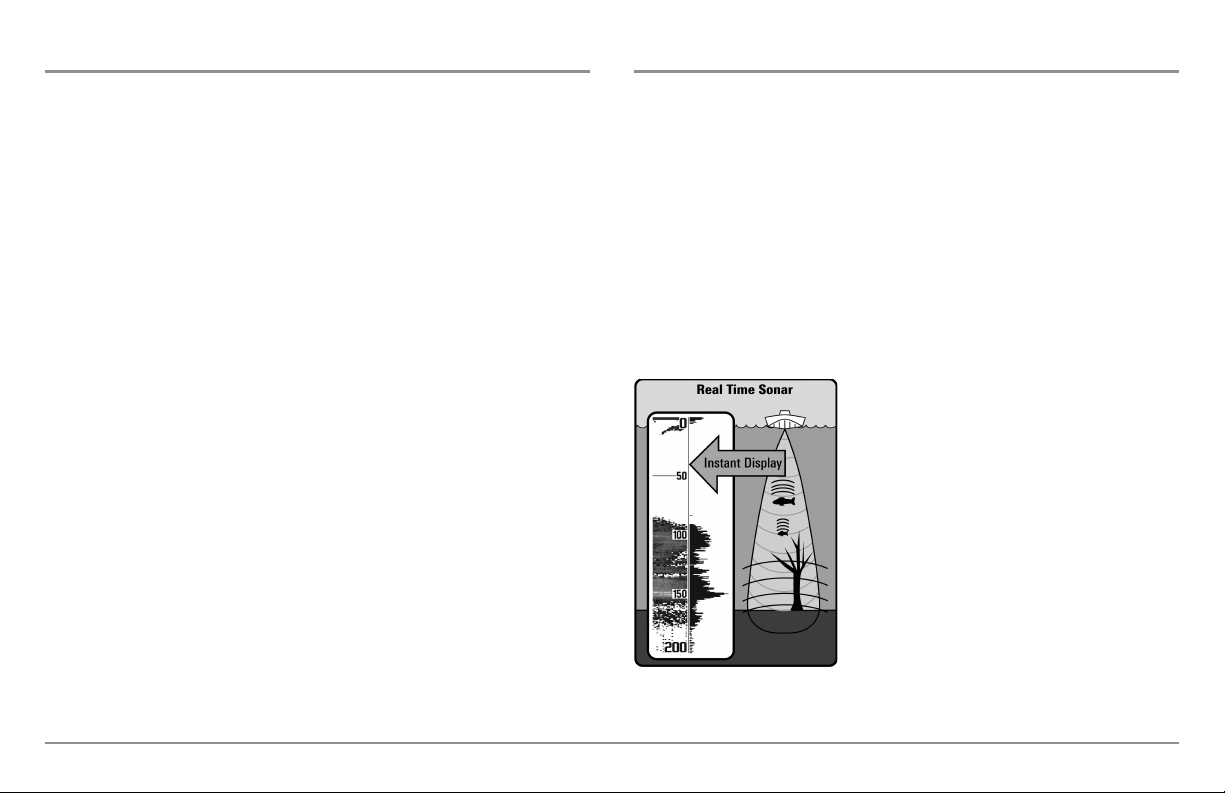
The sound pulses "echo" back from objects in
the water such as the bottom, fish and other
submerged objects. The returned echoes are
displayed on the LCD screen. Each time a new
echo is received, the old echoes are moved
across the LCD, creating a scrolling effect.
1
Introduction
When all the echoes are viewed side by side,
an easy to interpret "graph" of the bottom, fish
and structure appears.
The sound pulses are transmitted at various
frequencies depending on the application.
Very high frequencies (455 kHz) are used for
greatest definition, but the operating depth is
limited. High frequencies (200 kHz) are
commonly used on consumer sonar and
provide a good balance between depth
performance and resolution. Low frequencies
(83 kHz) are typically used to achieve greater
depth capability.
The power output is the amount of energy
generated by the sonar transmitter. It is
commonly measured using two methods:
• Root Mean Square (RMS) measures power
output over the entire transmit cycle.
• Peak to Peak measures power output at the
highest points.
The benefits of increased power output are
the ability to detect smaller targets at greater
distances, ability to overcome noise, better
high speed performance and enhanced depth
capability.
Introduction
2
75 Degree Total Coverage
16°
75°
25°
455kHz
200kHz
455kHz
45°
800kHz
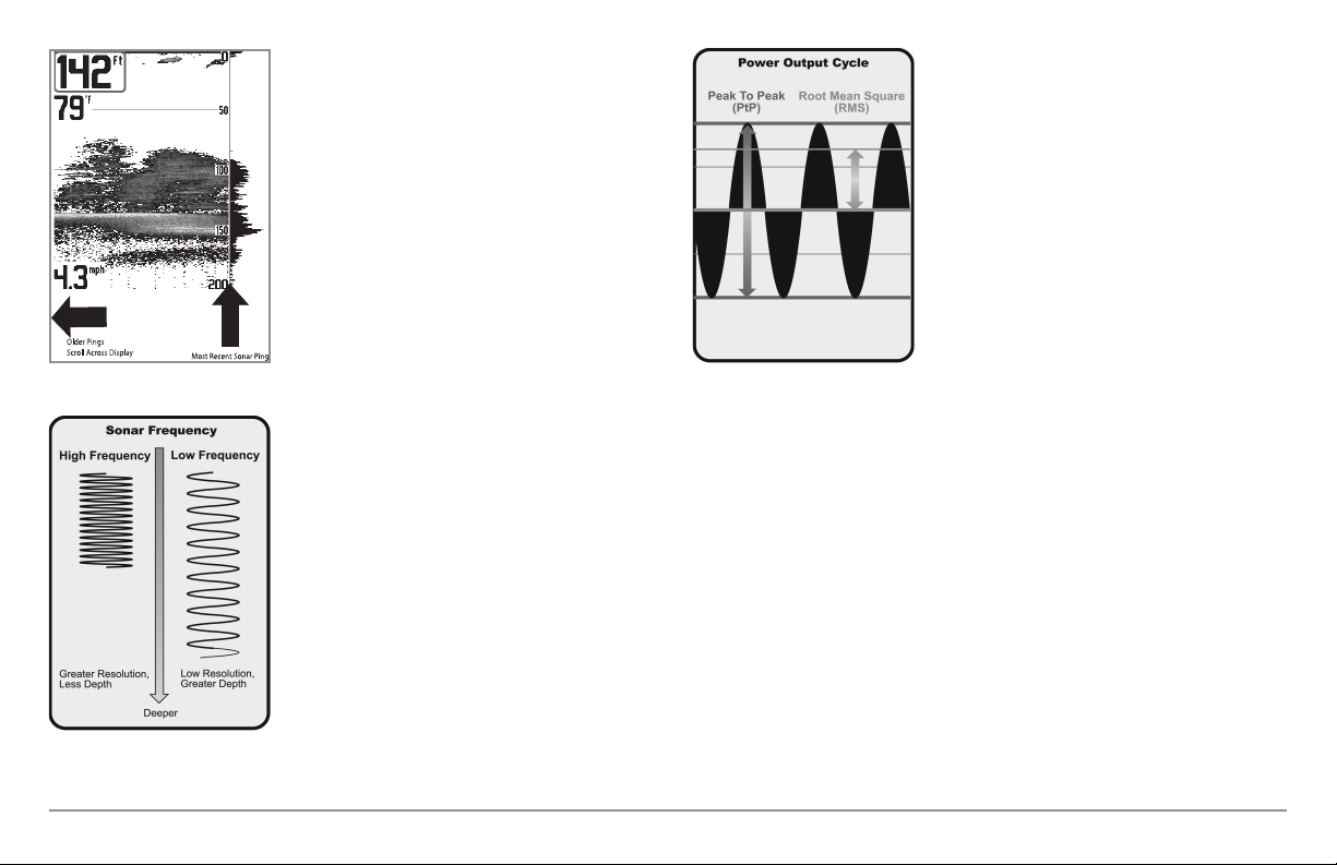
DualBeam PLUS™ Sonar
(DualBeam PLUS™ models only
[858c HD, 898c HD SI, 958c HD, & 998c HD SI])
The 858c HD/958c HD Combo and 898c HD
SI/998c HD SI Combo Fishing Systems use
a 200/83 kHz DualBeam PLUS™ sonar
system with a wide (60°) area of coverage.
DualBeam PLUS™ sonar has a narrowly
focused 20° center beam, surrounded by a
second beam of 60°, expanding your
coverage to an area equal to your depth. In
20 feet of water, the wider beam covers an
area 20 feet wide.
DualBeam PLUS™ sonar returns can be
blended together, viewed separately, or
compared side-by-side. DualBeam PLUS™ is
ideal for a wide range of conditions - from
shallow to very deep water in both fresh and
salt water. Depth capability is affected by
such factors as boat speed, wave action,
bottom hardness, water conditions, and
transducer installation.
Down Imaging™ Sonar
(Down Imaging™ models only [858c HD DI
and 958c HD DI])
The 858c HD DI/958c HD DI Combo
Fishing System uses Down Imaging™
technology. The Down Imaging™
transducer scans the water with razorthin, high-definition beams. The beams
are wide (side to side) but very thin front
to back.
The Down Imaging™ beams can be
operated at two frequencies: 455 kHz
(75°) or 800 kHz (45°). Select 455 kHz for
the best overall image quality and depth.
Select 800 kHz for the sharpest image.
See Down Imaging™ X-Press™ Menu:
Imaging Frequency for more information.
The transducer also uses conical beams to provide data in traditional 2D
format (see What’s on the Sonar View). Select 455 kHz for a narrowly
focused 16° center beam, or select 200 kHz for a wider 25° beam (see Sonar
Menu Tab: Beam Select).
Depth capability is affected by such factors as boat speed, wave action,
bottom hardness, water conditions, and transducer installation.
3
Introduction
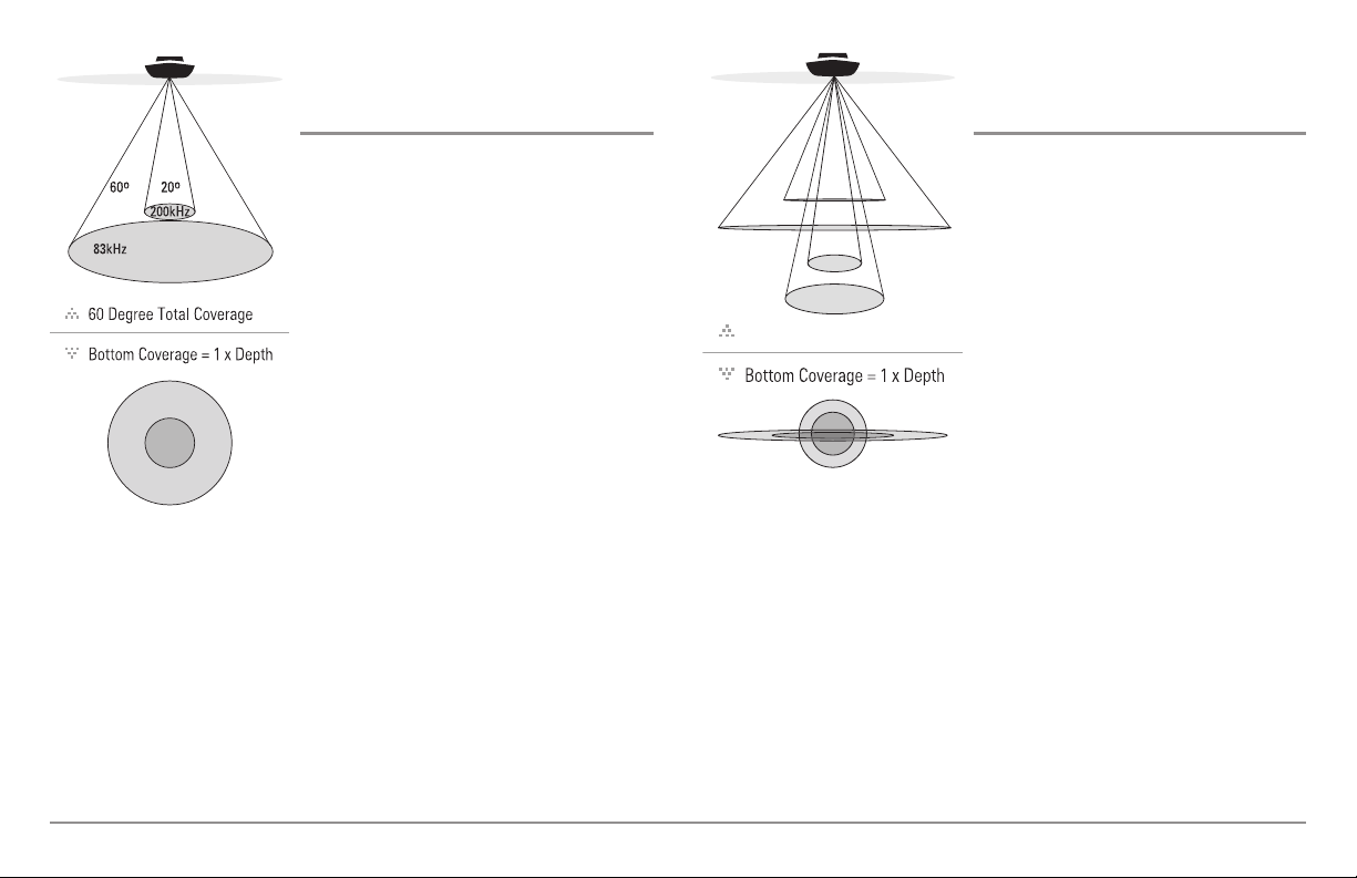
High Definition
6
0°
8
3kHz
20°
2
00kHz
86°
455kHz
86°
455kHz
Side Imaging
(Side Imaging® models only
[898c HD SI and 998c HD SI only])
The 898c HD SI/998c HD SI Combo
Fishing System uses Side Imaging®
sonar to provide a wide yet precise survey
of a large area of water, including
detailed bottom topography and fishattracting structure orientation. The Side
Imaging® transducer returns are
processed into an image similar to an
aerial photograph.
Typically, the Side Imaging® sonar can search an area that is 480 feet wide
(240 to each side), with a typical depth performance of 150 feet when the
Side Imaging® Sonar frequency is set for 455 kHz. The side beams can be
operated at one of two frequencies: 455 kHz or 800 kHz. Selecting 800 kHz
produces the sharpest image, but the search area to each side and the depth
capability are limited as compared to the 455 kHz frequency. See What’s on
the Side Imaging® Display and Understanding Side Imaging® for more
information.
The Side Imaging® transducer also provides down imaging displays on the
screen. See What's on the Down Imaging™ Display for more information.
® Sonar
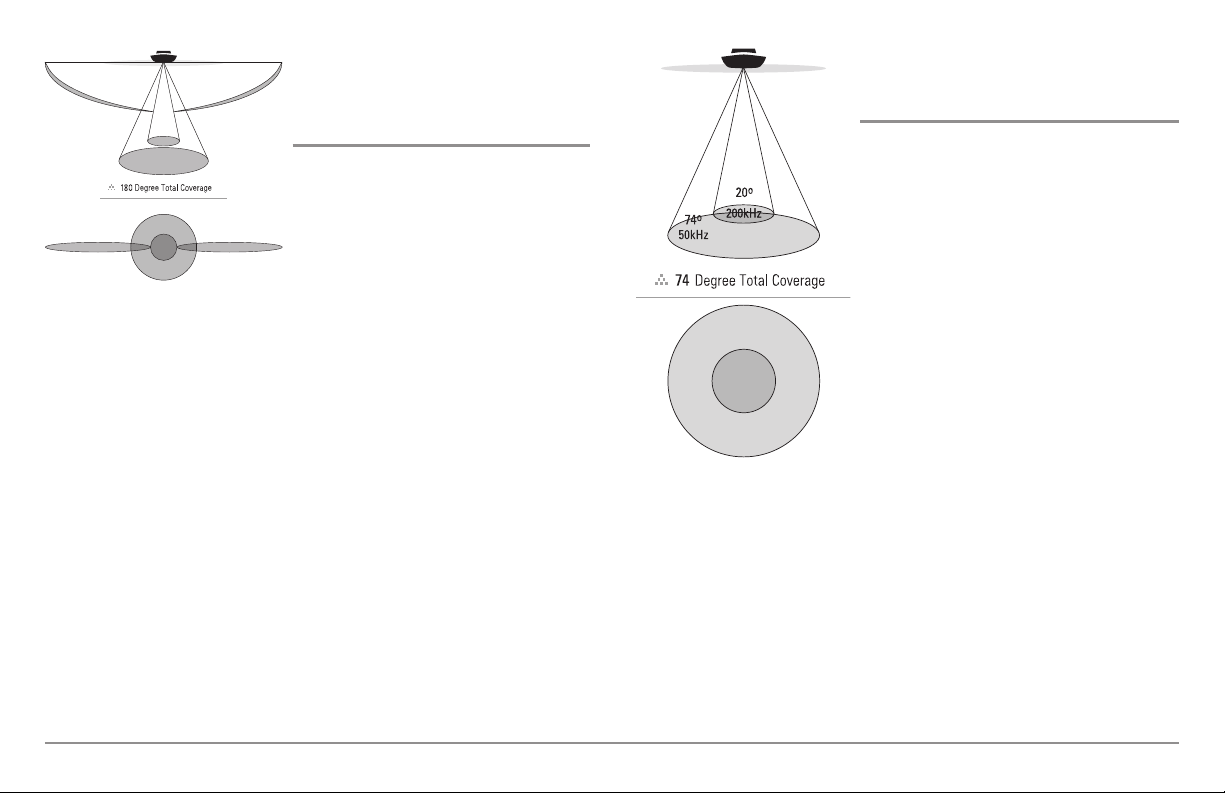
Xtreme Depth Sonar
(Xtreme Depth Series™ models only [858c HD
XD and 958c HD XD])
The 858c HD XD/958c HD XD Combo
Fishing System uses the XD transducer to
provide extreme depth coverage with
DualBeam PLUS™ technology.
The Xtreme Depth sonar beams can be
operated at two frequencies: 50 kHz (74°)
and 200 kHz (20°). The wide, 50 kHz beam
transmits at a low frequency to provide
greater depth coverage, up to 2500 ft (762
m). The narrow, 200 kHz center beam
transmits at a high frequency to provide
maximum detail at shallower depths.
The DualBeam PLUS™ technology allows
you to view the sonar returns blended
together, separately, or side-by-side (see
Sonar Menu Tab: Beam Select and Views
for more information).
Depth capability is affected by such factors as boat speed, wave action,
bottom hardness, water conditions, and transducer installation.
Introduction
4
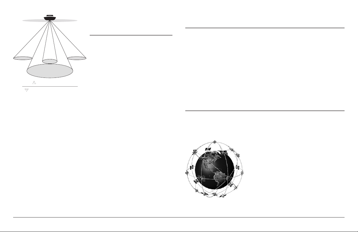
QuadraBeam PLUS™ Sonar
90° Total Coverage
Bottom Coverage=2 x Depth
35° 60° 20° 35°
455 kHz 455 kHz
83 kHz
200 kHz
(with optional-purchase QuadraBeam
PLUS™ transducer)
QuadraBeam PLUS™ sonar provides a
wide 90° area of coverage.
QuadraBeam PLUS™ starts with two
fan-shaped 35° 455 kHz Side Structure
locating sonar beams to spot fish, bait,
and structure to the left and right of the
boat over an area of the bottom that’s
always equal to twice your depth.
Universal Sonar 2
(compatible w/optional-purchase Minnkota trolling motors)
Your Fishing System supports Universal Sonar 2, a state-of-the-art,
integrated and protected transducer that is built into the lower unit of
Minnkota trolling motors. With Universal Sonar 2, all wiring is concealed
inside the indestructible composite shaft—out of sight and out of harm’s
way, with no clamps, ties, or exposed wires. Universal Sonar 2 features new
temperature sensing and the performance of DualBeam PLUS™ technology
(available with all Humminbird® DualBeam PLUS™ models). An expanded
view and greater bottom detail gives you a totally new perspective of the
water below, along with optimal sonar performance to help you find fish.
For a detailed view below the boat,
QuadraBeam PLUS™ uses DualBeam
PLUS™ technology, with precision 20°
and wide 60° beams. QuadraBeam
PLUS™ finds more fish faster, and can
even tell you where to put your bait by
showing if fish are to the left, right, or
directly beneath your boat.
NOTE: Contact our Customer Resource
Center to determine which accessory
transducers are compatible with your
Humminbird® Fishing System, or visit our Web
humminbird.com.
site at
How GPS and Cartography Work
Your Fishing System also supports GPS (Global Positioning System) and
chartplotting. It uses GPS and sonar to determine your position, display it on
a grid, and provide detailed underwater information.
GPS uses a constellation of satellites that
continually send radio signals to the earth. The
GPS receiver on your boat receives signals from
satellites that are visible to it. Based on time
differences between each received signal, the
GPS receiver determines its distance to each
satellite. With distances known,the GPS receiver
mathematically triangulates its own position.
With 5 updates per second, the GPS receiver
then calculates its velocity and bearing.
5
Introduction
GPS was originally intended for military use; however, civilians may also take
advantage of its highly accurate position capabilities, typically within +/- 4.5
meters, depending on conditions. This means that 95% of the time, the GPS
receiver will read a location within 4.5 meters of your actual position. Your
GPS Receiver also uses information from WAAS (the Wide Area
Augmentation System), EGNOS (the European Geostationary Navigation
Overlay Service), and MSAS (the MTSAT Satellite Augmentation System)
satellites if they are available in your area.
The following GPS functionality is currently supported by the Fishing System
when it is connected to the included GPS receiver:
• View current position
• View current track (breadcrumb trail)
• View precision speed and heading from your GPS receiver
• Save tracks, waypoints, and routes
• Travel a route and navigate from one waypoint to the next.
See Chart View and SD Memory Card Slots: Add Maps to Your Fishing
System for more information.
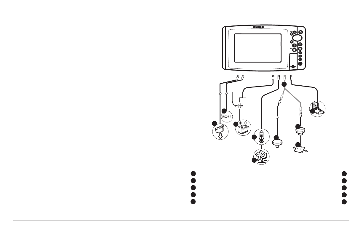
The Fishing System has a wide variety of configurations
6
2
1
3
4
5
7
8
9
10
Introduction
6
Video Out
1
RS 232 Connector
2
Power
3
Temperature
4
Speed
5
5
“Y” Cable
GPS Receiver
SmartCast® Wireless Sonar Link
WeatherSense®
Sonar Transducer with Temperature
6
7
8
9
10
Fishing System Configuration
The Fishing System has a wide variety of configurations that will influence the
installation. The accessory bus, video output, and RS 232 connectors allow you
to expand your Fishing System capabilities. As you expand the configuration,
the menu options that correspond with the connected accessory will be added
to the menu system.
Please read all instructions that are relevant for your configuration before
beginning the installation process. See the Humminbird® installation guide for
details.
Accessory Bus
Use the Accessory Bus to expand the
functionality of your Fishing System. Accessories
plug directly into the Fishing System and enable
advanced features such as WeatherSense®,
SmartCast®, and the AS WX 1 Satellite Weather
Receiver.
When an accessory is plugged into the Fishing
Accessory Bus
NOTE: Accessories to enable WeatherSense®, SmartCast®, and the AS WX 1 Satellite
Weather Receiver require separate purchases. Visit our Web site at humminbird.com
or contact our Customer Resource Center at 1-800-633-1468 for details.
NOTE: See your installation guide for details.
System, additional functions will be added to the
menu system automatically. See Accessories
Menu Tab in this manual, as well as your
accessory’s Operations Manual for additional
details.
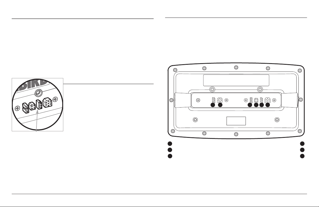
Video-Out and RS 232 Connectors
Your unit has a built-in Video Out connector and a dual RS 232 connector,
which can be used with optional-purchase equipment such as AIS
(Automatic Identification System). If you purchase a video monitor and
attach it to your control head using the Video Out connector, your unit will
send a video signal if it detects a monitor. See Setup Menu Tab: Video Out
for more information.
1 5 6
RS 232
1
Video Output
2
Power
3
NOTE: Accessories connected to the RS 232 or Video-Out connectors require a
separate power source.
NOTE: To purchase a connection cable for an optional-purchase AIS, visit our
Web site at humminbird.com or contact our Customer Resource Center
at 1-800-633-1468.
32 4
Temp/Speed
Communications/GPS
Transducer
4
5
6
7
Introduction
Ethernet Connector
Your unit has a built-in Ethernet connector so that you can network two
Humminbird® units. When you connect the units together using the
optional-purchase Humminbird® Ethernet cable, data is shared across the
two units and additional menu options are added to the
Menu System. See the Ethernet Operations Manual for details.
NOTE: The Ethernet cable requires a separate purchase. Visit our Web site at
humminbird.com or contact our Customer Resource Center at 1-800-633-1468
for details.
Power On
Follow the instructions below to power on your Humminbird® control head.
1. Press the POWER/LIGHT key to power on your Humminbird®
control head.
2. When the Title screen is displayed, press the MENU key to access
the Start-Up Options Menu.
3. If a functioning transducer is connected, Normal operation will be
selected automatically, and your Fishing System can be used on the
water. See Start-Up Options Menu for more information.
• If a transducer is not connected and you wait too long to select
a Start-Up Option, the system will default to whichever menu is
already highlighted.
• You can also select Simulator to learn how to use your control
head and save settings in advance for later use.
4. Quick Setup: If this is the first time the unit has been powered on
(after installation or after restoring defaults), the Quick Setup dialog
box will display on the screen. Use the 4-WAY Cursor Control key to
set the Language, Water Type, and Max Depth. Press the EXIT key
to close the dialog box.
NOTE: The Quick Setup settings can be changed at any time. See each menu
option in The Menu System for details.
Power On
998c HD SI Combo Title Screen
8
What’s on the Control Head
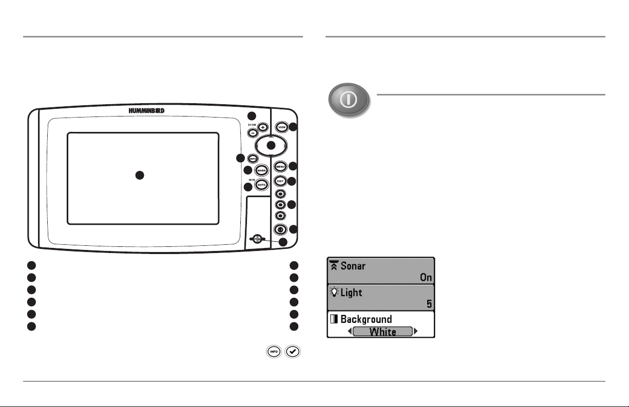
Key Functions
Your Fishing System user interface is easy to use. A combination of keys,
different views, and situation-specific, customizable menus allows you to
control what you see on the color display. Refer to the following illustration,
and see Key Functions, Views, and The Menu System for more information.
2
3
4
5
1
Screen Menu Key
1
ZOOM (+/-) Keys GOTO Key
2
View Key Exit Key
3
4-Way Cursor Control Key VIEW PRESET Keys
4
Info Key* Power/Light Key
5
MARK Key
6
6
8
SD Card Slot
7
9
10
11
12
7
8
9
10
11
12
*Your control head will have one of the INFO keys shown here .
Both keys function in the same way.
Your Fishing System has a set of easy to use keys that give you flexibility and
control over your fishing experience.
POWER/LIGHT Key
The POWER/LIGHT key is used to power the Fishing System
on and off. You can also use the POWER/LIGHT key to adjust
the backlight and contrast of the display.
Power On: Press the POWER/LIGHT key to power on the unit. When the Title
screen is displayed, press the MENU key to access the Start-Up Options
Menu.
Power Off: Press and hold the POWER/LIGHT key for 3 seconds. A message
will appear to indicate how many seconds there are until shutdown occurs.
To ensure that shutdown occurs properly and any menu settings will be
saved, your Fishing System should always be turned off using the
POWER/LIGHT key.
Adjust the Backlight or the Display
Background Color: Press the POWER/LIGHT
key to access the Light and Background
submenu. Use the 4-WAY Cursor Control key
to select Light or Background, and then use
the LEFT or RIGHT Cursor key to change the
settings. Press EXIT to exit the Light and
Background submenu.
NOTE: Your control head will start up with the backlight on and will
automatically turn it off to conserve power.
9
The Control Head, Key Functions
Turn Local Sonar On or Off: From the Light and Background submenu, use the
4-WAY Cursor Control key to select Local Sonar. Use the LEFT or RIGHT Cursor
key to change the setting. See Setup Menu Tab: Local Sonar for more
information.
NOTE: This feature may appear as either Sonar or Local Sonar, depending on
your model.
VIEW Key
The VIEW key is used to cycle through all available views.
Press the VIEW key to advance to the next view. Press the
VIEW key repeatedly to cycle through all available views.
Views can be hidden to optimize the system to your fishing
requirements (see Views or Views Menu Tab).
MENU Key
The MENU key is used to access the menu system. See The
Menu System for more information.
Start-Up Options Menu: Press the MENU key during the power up
sequence to view the Start-Up Options menu.
4-WAY Cursor Control Key
(RIGHT, LEFT, UP, or DOWN Cursor Keys)
The 4-WAY Cursor Control key has multiple functions,
which depend on the view, menu, or situation.
• Menu Selection: Press the DOWN or UP Cursor keys to highlight a
menu option, then press the RIGHT or LEFT Cursor keys to change a
menu setting. The changes will be activated and saved immediately.
• Freeze Frame: In Sonar View, Side Imaging® View, and Down
Imaging™ View press any arrow on the 4-WAY Cursor Control key to
freeze the display and move the active cursor to a location on the
screen. A cursor dialog box will display to show the depth of the
location you choose.
• Active Cursor: Press any arrow on the 4-WAY Cursor Control key, and
the active cursor will appear on the screen.
• Chart Views: The 4-WAY Cursor Control key also pans the charts and
highlights decluttered waypoint icons.
NOTE: In Freeze Frame or Active Cursor mode, you can also make the
cursor move diagonally by pressing in between two of the arrows on the
4-WAY Cursor Control key.
X-Press™ Menu: Press the MENU key once in any view to access the
X-Press™ Menu, which provides frequently-used menu settings that
correspond with the current view or navigation mode.
Main Menu: Press the MENU key twice in any view to access the Main
Menu, which is organized under tabbed headings to help you find a specific
menu item quickly.
Key Functions
• Bird’s Eye View: The 4-WAY Cursor Control key controls the motion
of the eye point.
• Snapshot and Recording View: Press the UP or DOWN Cursor keys
to highlight a recording icon, and then press the RIGHT Cursor key to
start recording playback. Press the RIGHT or LEFT Cursor keys to
control the speed of playback.
10
VIEW PRESET Keys
INFO Key
The VIEW PRESET keys are used to save your three favorite
views for quick retrieval. Instead of using the VIEW key to
cycle through all the views to find the one you want, you can
program the VIEW PRESET keys to display a specific view
immediately. See Views for more information.
EXIT Key
The EXIT key has multiple functions, which depend on the
situation:
• If an alarm is sounding, press the EXIT key to cancel the alarm.
• If a menu tab is selected, press the EXIT key to exit the menu mode
and return to the view.
• If a menu is active, press the EXIT key to return to the previous level
in the menu system.
• From any view, press the EXIT key to cycle through the available
views in reverse order.
• If Freeze Frame is active, press the EXIT key to return to a scrolling
display.
• If the Cursor is active, press the EXIT key to remove the cursor from
the display.
Press the INFO key while in Bird's Eye, Chart, or Combo View
to display information about objects that are near an active
cursor. If the cursor is not active, the Chart Info submenu will
be displayed. See Views: Viewing Cartography for more
information.
NOTE: Your control head will have one of the INFO keys shown
here. Both keys function in the same way.
MARK Key
Press the MARK key while in any view to mark the position of
a waypoint. The MARK key function is available if the GPS
receiver is connected.
• Active Cursor: The waypoint will be marked at the cursor location.
• Without Active Cursor: The waypoint will be marked at the boat
location.
• If Screen Snapshot is active, a waypoint will be created, and a
screen snapshot will also be saved to the optional-purchase SD card
(see Views: Snapshot and Recording View). Navigation is not
affected by the Screen Snapshot feature.
NOTE: If Screen Snapshot is enabled but there is not a GPS receiver
connected, pressing the MARK key will capture the screen image and display
an error saying that a GPS position fix is required to create a waypoint.
NOTE: You must have an optional-purchase SD card installed for the screen
snapshot feature to work.
11
Key Functions
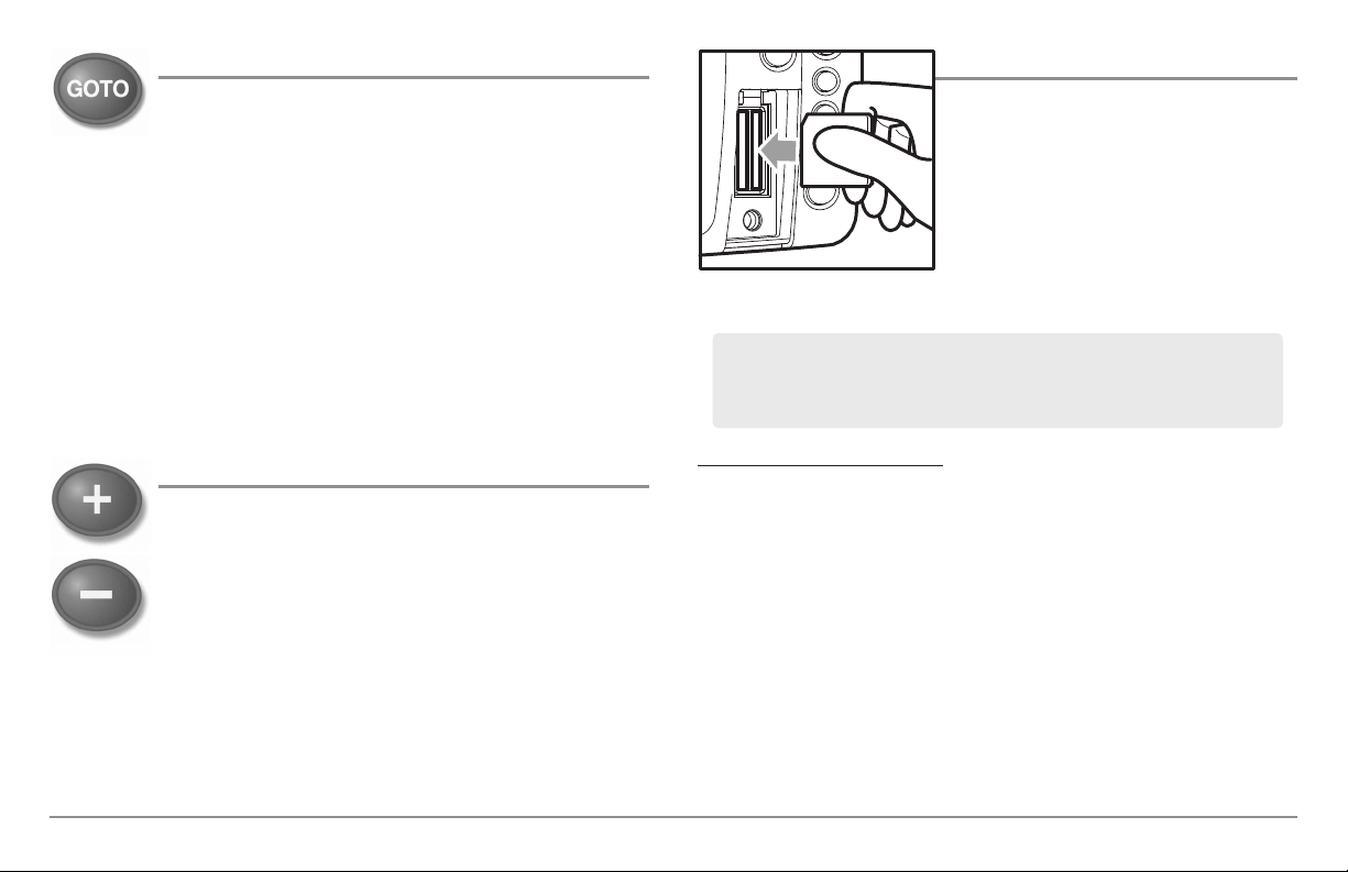
GOTO Key
The GOTO key has multiple functions, which depend on the
situation.
• Active Cursor: Press the GOTO key while in any view to create a
waypoint and start navigation towards that waypoint.
• Without Active Cursor: Press the GOTO key to display the saved
waypoints list, and then highlight a waypoint. Press the RIGHT
Cursor key to begin navigation.
• Man Overboard: Press and hold the GOTO key for more than 1.5
seconds to activate the Man Overboard (MOB) function. Once MOB
is activated, any current navigation will be cancelled and the current
route will be discarded without notification (see Man Overboard
(MOB) Navigation).
SD Memory Card Slots
The two SD memory card slots on your
control head can be used with SD memory
cards (optional-purchase required) to add
detailed charts to your Fishing System,
update your Fishing System software, or
export navigation data from your Fishing
System.
Inserting an SD Card
into the Card Slot
NOTE: The SD Memory Cards require a separate purchase. For more
information, visit our Web site at humminbird.com or contact our Customer
Resource Center at 1-800-633-1468.
ZOOM (+/-) Keys
The Zoom keys function in different ways which depend on
the view displayed.
• Navigation Views or the Sonar Zoom View: Press the
+/- ZOOM key to change the scale of the view to appear
closer or farther away.
• Side Imaging® View or Down Imaging™ View: Use the
4-WAY Cursor Control key to move the active cursor to a
position on the screen. Press the + ZOOM key to magnify
your selection. Press the -Zoom key to decrease the scale.
NOTE: The cursor must be active for the zoom feature to work in the Side
Imaging® or Down Imaging™ View.
Key Functions, SD Memory Card Slots
To insert an SD memory card:
1. Remove the SD memory card slot cover.
2. Position the SD memory card so that the label faces the left side of the
unit, and insert the card into the slot. Press down on the card until it
clicks into place.
3. Close the slot cover and turn the knob just 1/4 of a turn to close. Do
NOT overtighten, as this will not improve water resistance and may
damage the cover.
4. To Remove: Press the SD memory card into the slot and then release.
The card will eject, and you can then pull the card from the slot.
NOTE: Do not leave the SD slot cover open. The slot cover should always be
closed to prevent water damage to the unit.
12

Add Maps to Your Fishing System
Your Fishing System includes a built-in Contour XD™ or UniMap™ with a
more detailed map of North America (Domestic models) or a detailed map of
Europe and Southeast Asia, including Australia and New Zealand
(International models).
You can also purchase SD memory cards with additional chart information
for a particular location.
Import Navigation Data
Review the following information before importing navigation data
(waypoints, routes, tracks, or groups) into your Humminbird® unit.
• Import Humminbird® Navigation Data: Insert a loaded SD card into
the control head card slot, and follow the on-screen prompts to
import the waypoints, routes, tracks, and groups. In certain models,
the data will import automatically.
NOTE: The 800/900 Series™ supports LakeMaster®, Navionics® Gold,
HotMaps®, HotMaps® Premium, and Platinum™ Cartography on SD card
media. The 800/900 Series™ does not support Navionics® Classic Charts.
NOTE: The SD Memory Cards require a separate purchase.
• Auto Select: When you install the SD cards in your control head, your
Fishing System will retrieve the chart and display it automatically.
• Chart Select: You can also choose which chart to display with the
Chart Select menu option in the Chart Menu Tab. Choose Right (card
slot) or Left (card slot) to select the SD card you’d like to use (see
Chart Menu Tab: Chart Select).
• Chart Layers: You can customize your Navigation Views by selecting
which chart layers to display or hide (see Chart Menu Tab: Chart
Detail Level).
• Map Borders: Use the 4-WAY Cursor Control key to move the active
cursor within a map border, and press the ZOOM + key to view the
different map (see Chart Menu Tab: Map Borders).
• Menu Options: The Chart Menu Tab will change to display menu
options that correspond with the active chart (see Chart Menu Tab).
WARNING! DO NOT import navigation data from unknown sources into your
Humminbird® unit without first converting the data to the correct format using
HumminbirdPC™. Importing corrupted data can cause the unit to malfunction,
which can result in lost navigation data.
NOTE: For more information and instructions, see the FAQ (Frequently Asked
Questions) section of our Web site at humminbird.com or call our Customer
Resource Center at 1-800-633-1468.
Export Navigation Data
The Humminbird® Waypoint Management dialog box allows you to export all
of your navigation items to an installed, unlocked SD Card. You can also
export selected items.
For more information, see Introduction to Navigation: What’s on
the Waypoint Management Dialog Box. Also, see your
Humminbird® Waypoint Management Guide for complete details.
It is important to back up your control head’s data files (waypoints,
routes, tracks, groups, recordings, etc.) periodically. You can also
save, view, and organize your navigation data on your PC using
HumminbirdPC™. See your Humminbird® online account for
details at humminbird.com.
13
SD Memory Card Slots

To export all navigation data:
Use the following instructions to export all of the control head’s waypoints,
routes, tracks, and groups to an installed, unlocked SD card.
1. Insert an unlocked SD card into the SD card slot.
2. Open the Waypoint Management Dialog Box: Press the MENU key
twice. Press the RIGHT Cursor key until the Navigation tab is selected.
Select Waypoints, Routes, Tracks. Press the RIGHT Cursor key.
3. Select Options > Select All and... > Export.
4. Follow the on-screen instructions to confirm or cancel the export.
To export selected navigation items:
Use the following instructions to select and export specific waypoints,
routes, tracks, and groups to an installed, unlocked SD card.
1. Insert an unlocked SD card into the SD card slot.
2. Open the Waypoint Management Dialog Box: Press the MENU key
twice. Press the RIGHT Cursor key until the Navigation tab is
selected. Select Waypoints, Routes, Tracks. Press the RIGHT Cursor
key.
3. From a selected group directory in the Waypoint Management
dialog box, select Options > Select Multiple and... > Export.
5. Confirm Export: When you are finished selecting items, press the
EXIT key to select Export Selected. Press the RIGHT Cursor key and
follow the on-screen instructions to confirm or cancel the export.
NOTE: If an SD memory card is not installed, an error message will be displayed.
Insert the SD memory card and try again.
NOTE: The SD memory cards and USB Memory Card Reader require separate
purchases. TheUSB Memory Card Reader accessory canbe used in conjunction with
your personal computer to view and organize your exported navigation data. To
purchase this accessory, visit our Web site at
Customer Resource Center at
1-800-633-1468.
humminbird.com or contact our
4. Select Items: Press the UP or DOWN Cursor keys to scroll through
the waypoints, routes, tracks, and groups. Press the RIGHT Cursor
key to select an item. Repeat as needed.
SD Memory Card Slots
14

Update Software
Set up an online account at humminbird.com so that you will receive the
latest Humminbird® news and software upgrades for your Fishing System.
You can also download HumminbirdPC™ from your account, which allows
you to manage your waypoints, routes, and tracks on your personal
computer.
To update the control head software:
1. Install a formatted SD memory card into the card reader connected
to your PC.
2. Register your Fishing System: Log on to humminbird.com. Click My
Account. Set up a new account.
NOTE: It is important to back up your control head’s data files (waypoints,
routes, tracks, groups, recordings, etc.) periodically. Data files should also be
saved to your PC before restoring the unit’s defaults or updating the software.
See Export Navigation Data and Snapshot and Recording View for more
information. Also, contact our Customer Resource Center with any questions.
Required Equipment: Personal computer with Internet access, a formatted
SD memory card, and USB Memory Card Reader.
NOTE: To purchase the USB Memory Card Reader (AS CR) visit our Web
site at humminbird.com or contact our Customer Resource Center at
1-800-633-1468. Our Customer Resource Center will also assist you with any
questions you might have about updating your Humminbird® Fishing System.
3. Download: From My Account\My Profile\My Equipment, click the
file name of the latest software update (unit name [version #]).
• Read the instructions in the dialog box and click Download.
• Follow the prompts to save the software file directly to the
SD Card.
4. Install the SD card with the updated software file into the control
head card slot.
5. Power on your Fishfinder. The control head will recognize the new
software and run through a series of prompts to confirm software
installation.
15
SD Memory Card Slots
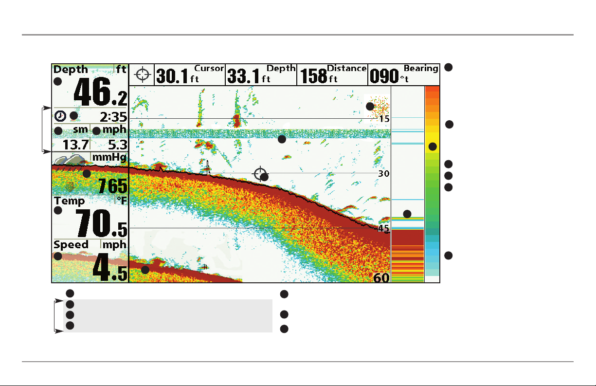
What’s on the Sonar Display
The Fishing System can display a variety of useful information about the area under and adjacent to your boat, including the following items:
Thermoclines - Layers of water with
8
1
10
2
3
Triplog
6
4
8
5
13
11
7
12
Depth - Water depth; can be set to alarm when the water becomes too shallow.
1
Timer - Elapsed time with Speed accessory or GPS Receiver.
2
Distance - Distance traveled with Speed accessory or GPS Receiver.
3
Triplog
Average Speed - Average speed reading with Speed accessory or GPS Receiver.
4
Barometric Pressure - Requires optional-purchase
5
WeatherSense®.
Temperature - Water surface temperature.
6
Speed - If a Speed accessory or GPS Receiver is attached,
7
the Fishing System can display the speed of the boat, and
can keep a triplog of nautical or statute miles traveled.
different temperatures that appear at
different depths and different times of the
year. A thermocline typically appears as a
continuous band of many colors moving
across the display at the same depth.
Sonar Color Bar - Color spectrum
9
indicating low to high sonar intensity
returns, where red indicates high intensity
9
and white indicates low intensity.
Bait Ball
10
RTS (Real Time Sonar) Window™
11
Second Sonar Return - When the sonar
12
signal bounces between the bottom and the
surface of the water and back again. Use
the appearance of the second return to
determine bottom hardness. Hard bottoms
will show a strong second return, while soft
bottoms will show a very weak one or none
at all.
Cursor - Available in Freeze Frame and can
13
be positioned in the Sonar View to provide
depth of a sonar retun and bottom depth
below the cursor. The Latitude and
Longitude of the cursor position, the
distance to travel to the cursor position, and
the bearing to the cursor position are
shown with a GPS Receiver attached.
Cursor information is displayed at the top of
the screen.
What’s on the Sonar Display
16
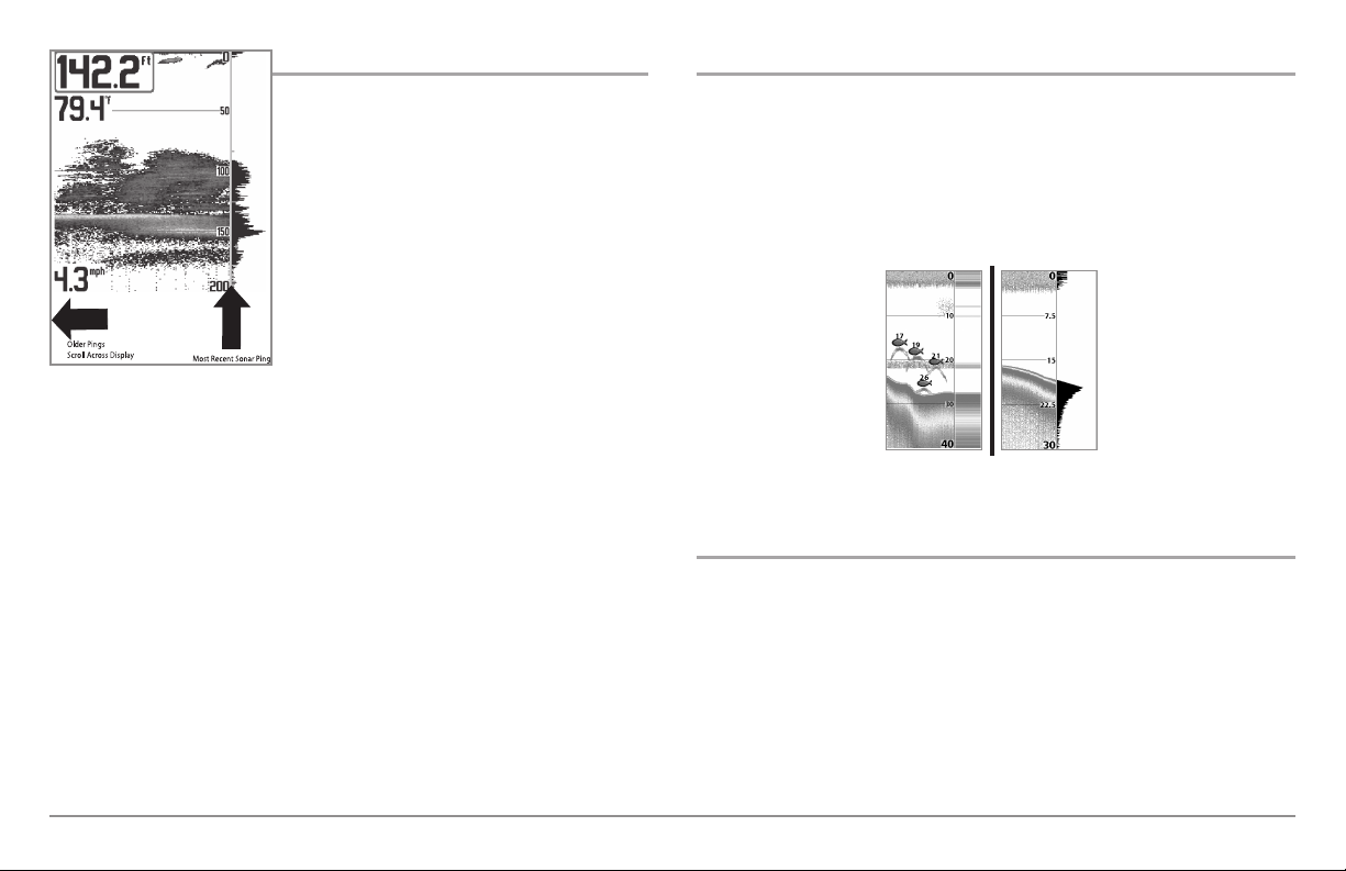
Understanding the Sonar Display
It is important to understand the
significance of the display. The display does
NOT show a literal 3-dimensional
representation of what is under the water.
Each vertical band of data received by the
control head and plotted on the display
represents something that was detected by
a sonar return at a particular time. As both
the boat and the targets (fish) may be
moving, the returns are only showing a
particular segment of time when objects
were detected, not exactly where those
objects are in relation to other objects
shown on the display.
The returned sonar echoes are displayed on the screen. As a new echo is
received, the historical data scrolls left across the display.
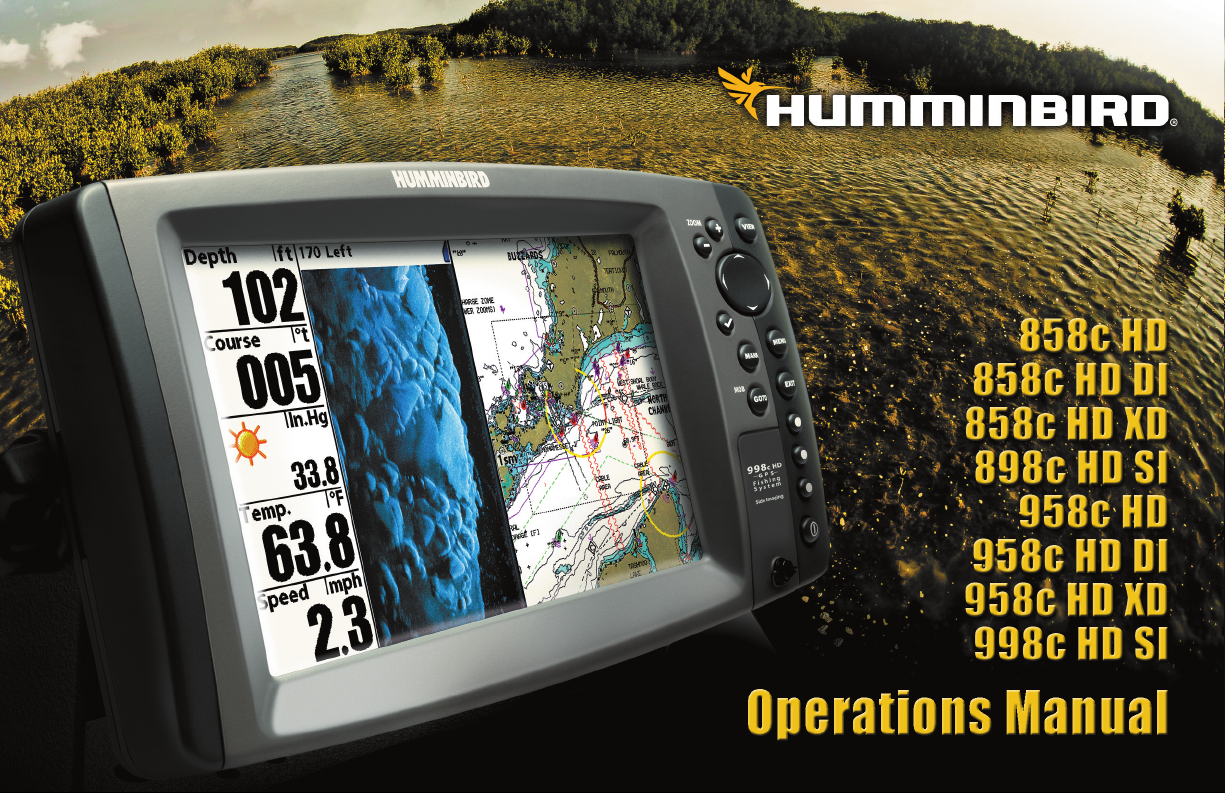
Real Time Sonar (RTS™) Window
A Real Time Sonar (RTS™) Window appears on the right side of the display
in the Sonar Views. The RTS Window™ always updates at the fastest rate
possible for depth conditions and shows only the returns from the bottom,
structure and fish that are within the transducer beam. The RTS Window™
plots the depth and intensity of a sonar return. (See Sonar Menu Tab: Real
Time Sonar (RTS™) Window).
TheNarrow RTS Window™
indicates the sonar intensity
through the use of colors.
Redindicates a strong return
and blue indicates a weak
return. The depth of the
sonar return is indicated by
the vertical placement of the
return on the display depth
scale.
The Wide RTS Window™
indicates the sonar intensity
through the use of a bar
graph. The length of the
plotted return provides an
indication of whether the
return isweakor strong. The
depth of the sonar return is
indicated by the vertical
placement of the return on
the display depth scale.
SwitchFire™
SwitchFire™ controls how the sonar returns are displayed in the Sonar
Views. SwitchFire™ settings are available in the Sonar Menu Tab.
To see the maximum sonar information available within the transducer beam
so more fish arches and better jig tracking are shown, choose Max Mode.
To see less clutter and more fish size accuracy interpreted from the
transducer beam, choose Clear Mode. See Sonar Menu Tab: SwitchFire™
for more information.
17
What’s on the Sonar Display
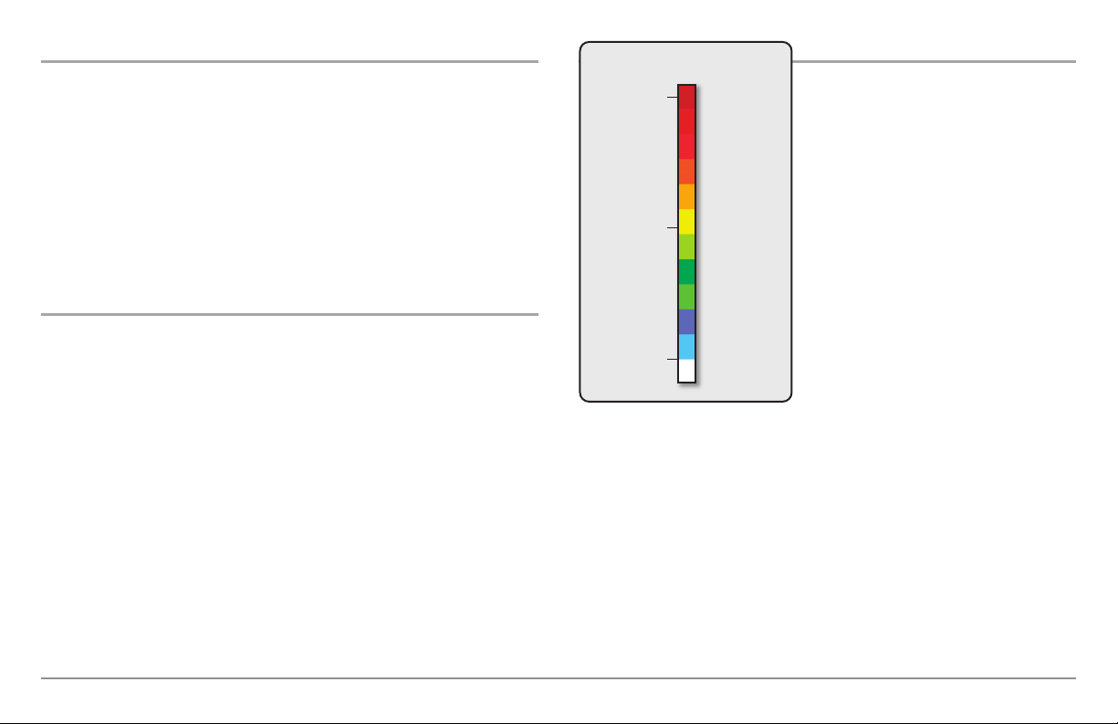
Freeze Frame and Active Cursor
Freeze Frame & Active Cursor - Press any arrow on the 4-WAY Cursor
Control key, and the screen will freeze and a cursor will be displayed. Use the
4-WAY Cursor Control key to move the cursor over a sonar return, and the
depth of the sonar return will be displayed at the top of the screen in the
cursor dialog box.
Sonar Colors: Original Palette
HIGH
Intensity Return
Sonar Colors and Bottom View
As the boat moves, the unit charts the
changes in depth on the display to create
a profile of the Bottom Contour. The
Sonar View displays the sonar return
intensity with different colors.
The RTS Window™ continues to update in Freeze Frame. To return to a
scrolling display and exit Freeze Frame, press the EXIT key. Freeze Frame is
available in the Sonar, Split Sonar, and Sonar Zoom Views.
Instant Image Update
Instant Image Update - You can change a variety of sonar menu settings
(such as Sensitivity or Upper Range), and the adjustments will be shown
instantly on the screen.
What’s on the Sonar Display
18
MEDIUM
Intensity Return
LOW
Intensity Return
Strong returns often result from rocky or
hard bottoms (compacted sediment,
rocks, fallen trees), while weaker returns
often result from soft bottoms (sand,
mud), vegetation, and small fish.
The colors used to represent high,
medium, to low intensity returns are
determined by the palette you choose in
the Sonar Colors menu option. See Sonar
Menu Tab to set the Sonar Colors.
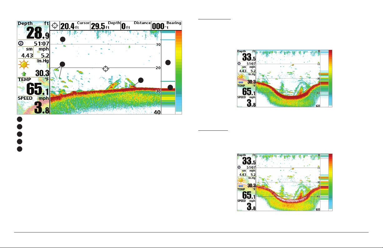
Sonar View: Original Palette
1
Structure ID® represents weak returns in blue and strong returns in red
when Sonar Colors is set to Original. If the Sonar Colors palette is changed,
the Structure ID® will display the strongest return as specified by the palette.
See Sonar Menu Tab: Sonar Colors for more information.
3
Sonar History: Historical returns scroll left across the view.
1
Strong Returns (possibly rocks, tree limbs, or other structure)
2
Weak Returns (possibly vegetation or small fish)
3
Strong Return (possibly compacted sediment or rocks)
4
RTS Window™
5
2
5
4
Use Bottom View to select the method used to represent bottom and
structure on the display. See Sonar Menu to set the Bottom View.
WhiteLine™ highlights the strongest sonar returns in white, resulting in a
distinctive outline. This has the benefit of clearly defining the bottom on the
display.
19
What’s on the Sonar Display
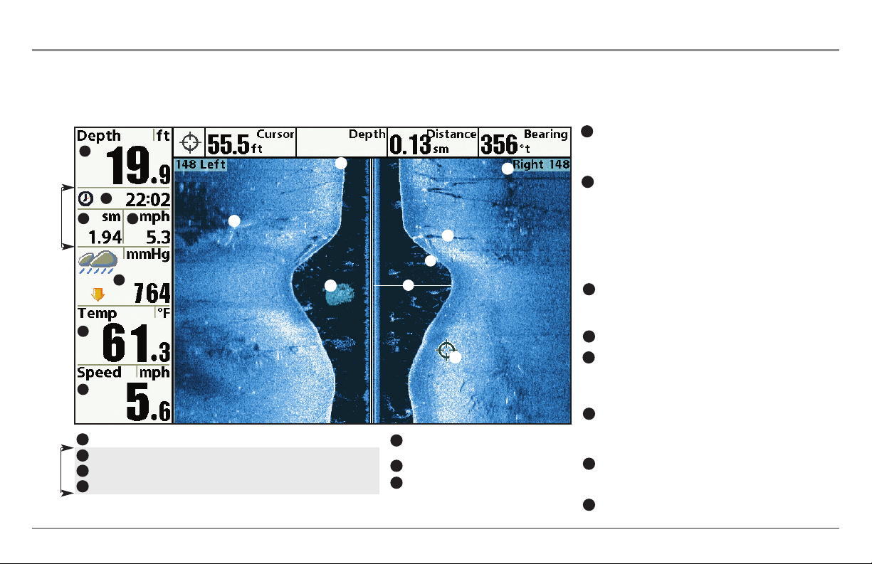
What’s on the Side Imaging® Display
(Side Imaging® models only [898c HD SI and 998c HD SI])
Side Imaging® displays a number of easily recognizable features that allow for accurate interpretation of bottom contour and structure. For Side Imaging®, the
bottom composition determines the intensity of the sonar return. For example, rock and gravel provide a clearer sonar return than mud and sand because of their
relative density. Upward slopes that face the transducer reflect sonar better than downward slopes that face away from the transducer. You can find a number of
easily recognizable features on the Side Imaging® display that allow for accurate interpretation of bottom contour and structure, including the following items:
Water column - Shows the relativedepth of thewater under the
8
1
2
3
Triplog
6
7
1
2
3
Triplog
4
What’s on the Side Imaging® Display
4
5
Depth - Water depth; can be set to alarm when the water becomes too shallow.
Timer - Elapsed time with Speed accessory or GPS Receiver.
Distance - Distance traveled with Speed accessory or GPS Receiver.
Average Speed - Average speed reading with Speed accessory or GPS Receiver.
13
10
9
11
15
8
12
14
Barometric Pressure - Requires optional-
5
purchase WeatherSense®.
Temperature - Water surface temperature.
6
Speed - If a Speed accessory or GPS Receiver is
7
attached, the Fishing System can display the
speed of the boat, and can keep a triplog of
nautical or statute miles traveled.
20
boat at a given time.Variations in the width of the water column
show variations in thedistance to thebottom as the boat passes
over.
Shadows - Result froma lack of reflectedsonar from a particular
9
area and can be more valuable for interpretation than the sonar
reflected by the object itself. Use shadows to help you see the
image in 3 dimensions, oriented in space. You can gain insight
into the actual shape of an object, or the depth to which it has
sunk into the bottom, through shadows on the display. Objects
standing on the bottom cast a sonar shadow. The longer the
shadow, the taller the object. Fish also cast shadows. You can
use the shadow to interpret how close the fish is to the bottom.
Topography Changes- The light part of the screen shows where
10
the beam is hittinghard bottom or rising terrain. The dark part of
the screen indicates soft bottom (sand, mud) or descending
terrain.
Bottom Return
11
Side Imaging® Range - Images shown on the right side of the
12
screen are located on the right side of your boat, and images
shown on the left side of the screen are located on the left side
of your boat. In this illustration, the sonar is pinging 148 feet
on each side.
Top of the Display - Information from the side beams are
13
displayed at the top of the screen. As new information is
received, the historical data scrolls down the screen. For the
most current information, watch the top of the screen.
Freeze Frame & Zoom - Use the 4-WAY Cursor Control key to
14
move the cursor to an area on the screen, and press the
ZOOM+ key to see the sonar returns in greater detail.
Clouded Area - May indicate a bait ball and White Streaks
15
may indicate fish.
 Loading...