

Page 1

INSTALLATION INSTRUCTIONS
Page 2
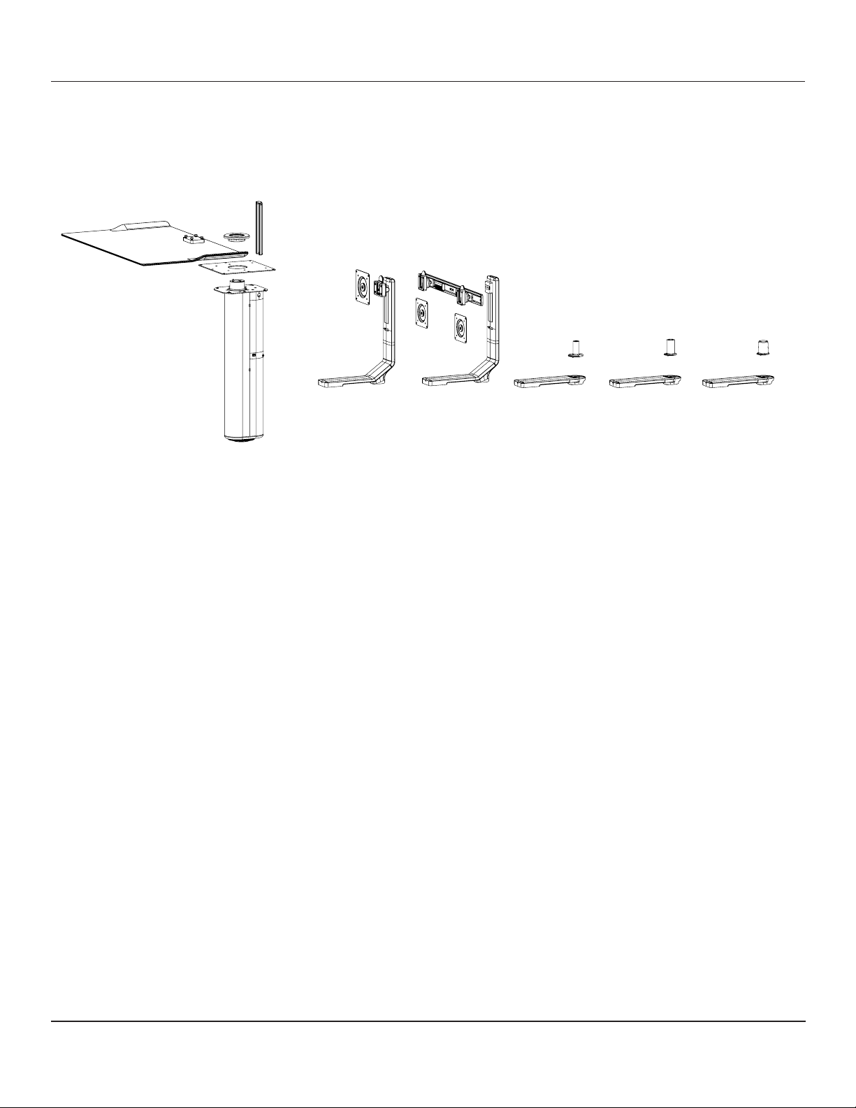
Tools required for installation
Cables required for installation
Parts in the box
3.25” hole saw
Philips head screw driver
10mm open end wrench
4/6/8mm hex keys
(2/2.5mm hex key- monitor arm mount)
10’ Power cord (x2 for dual monitor)
10’ VGA/DVI Cable (x2 for dual monitor)
PARTS REQUIRED
Dual monitorSingle monitor M2 M/FlexM8
+
(package contents will depend on configuration ordered)
Tools required for installation
6.0 mm Hex Key (included)
4.0 mm Hex Key (included)
3.0 mm Hex Key (included)
3.25” hole saw
Phillips head screw driver
10mm open end wrench
2.5 mm Hex Key for M8 (included)
2.0 mm Hex Key for M/Flex (included)
Cables required for installation
10’ Power cord (x2 for dual monitor)
10’ Monitor Signal Cable (X2 for dual monitor)
10’ USB extension cables (X2 for cable mouse & keyboard)
www.humanscale.comCustomer Service: N America +1 800 400 0625 / International +353 (0)1 858 0910
Page 3
STEP 1
Step 1
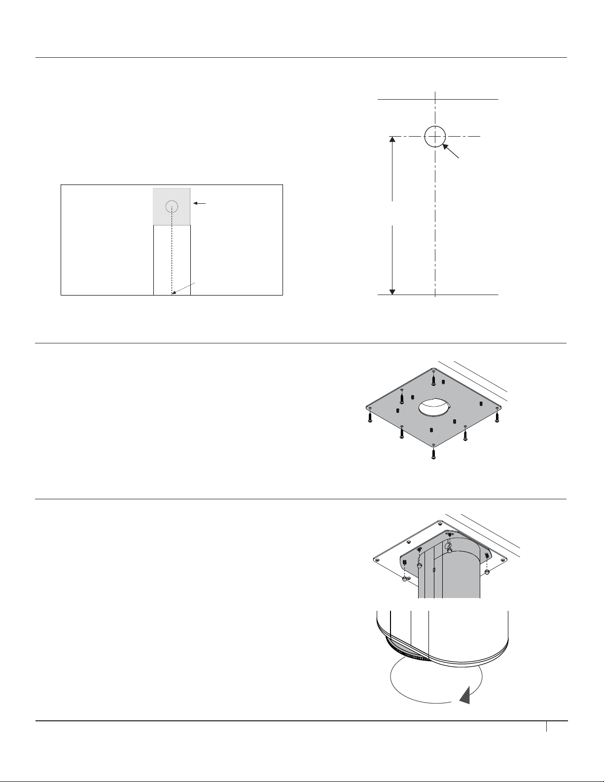
Place the paper template aligning to the front edge of the desk.
Make sure the 10” x 10” area shown on the template is clear of any obstruc-
tion underneath the desk for step2.
Drill 3.25” hole 24” from front edge in work surface shown in template.
*Desk size must be over 30” deep 3/4” thick.
Step 2
Install steel studded mounting plate to underside of desk, by aligning it
with 3.25” hole in desk. The cut out of the circle should face the back of the
desk.
Step 2
Install steel studded mounting plate to underside of desk, by aligning it
with 3.25” hole in desk. The cut out of the circle should face the back of the
desk.
Step 3
Mount main column to studded plate with plastic side facing rear and
secure with supplied lock nuts.
*Note studs are close to the column so a swivel socket works best.
Adjust foot of column.
*Do not over tighten foot as it will start to lift the desk.
Step 4
Loosen the screw located in the center of the locking mechanism.
Let the inner tube fully rise, then while pushing down the tube, ip down the
tabs on the locking mechanism shaft. The locking mechanism will be stored
inside the inner tube.
Step 2
Install steel studded mounting plate to underside of desk, by aligning it
with 3.25” hole in desk. The cut out of the circle should face the back of the
desk.
10” x 10” area
Align the template to the
front edge and centerline
of the desk
Locate and Drill Hole
• Place the paper template aligning to the front edge of the desk.
• Make sure the 10” x 10” area shown on the template is clear
of any obstruction underneath the desk for step 2.
• Drill 3.25" hole 24" from the front edge of the work surface shown in template.
*Desk size must be over 30" deep and 3/4" thick.
(Desk top view with template)
10” x 10” area
3.25”
24”
Align the template to the
front edge and centerline
of the desk
STEP 2
Install Mounting Plate
• Install steel studded Mounting Plate to underside of desk
by aligning it with 3.25” hole in desk. The cutout of the
circle should face the back of the desk.
STEP 3
Attach Column
• Mount main column to studded plate with plastic side
facing rear and secure with supplied lock nuts.
• Adjust foot of column.
*Do not over-tighten foot as it will start to lift the desk.
3
Page 4

STEP 4
Step 4
Loosen the screw located in the center of the locking mechanism.
Let the inner tube fully rise, then while pushing down the tube, ip down the
tabs on the locking mechanism shaft. The locking mechanism will be stored
inside the inner tube.
Step 6
Move to top of desk and install the Grommet Cover,
then the monitor stand to the column.
Feed all cables into the monitor stand.
Release Locking Mechanism
• Loosen the screw located in the center of the locking mechanism.
• Let the inner tube fully rise then, while pushing down the tube,
flip down the tabs on the locking mechanism shaft.
• The locking mechanism will be stored inside the inner tube.
STEP 5
Insert Cables
• Feed half of the length of both monitor power cables and video cables
through the 3.25” hole.
*Do not feed any USB cables during this step.
STEP 6
Install Grommet Cover and Monitor Arm
• Move to top of desk and install the Grommet Cover.
IF YOU ARE INSTALLING A SINGLE OR DUAL
MONITOR ARM, CONTINUE TO NEXT TASK.
IF YOU ARE INSTALLING AN M2, M8 OR M/FLEX,
PROCEED TO STEP 6 ON PAGE 8.
• Attach the monitor stand to the column.
• Feed all cables into the monitor stand.
4
Page 5
STEP 7 (FOR SINGLE/DUAL MONITOR)
Step 7
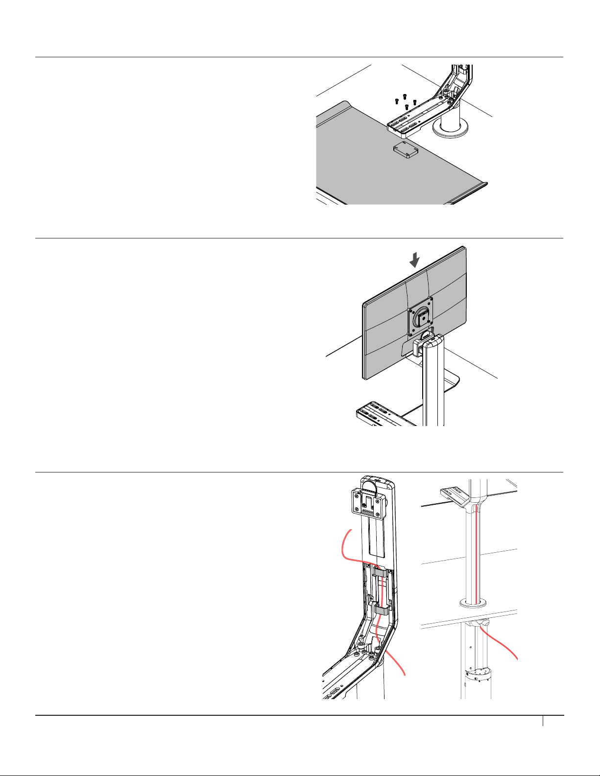
Next install keyboard tray.
Front edge of the keyboard tray must be at the front edge of the table.
Losen the 6 acorn nuts in step3 to rotate the unit for adjustment if needed.
Step 8
Attach the Vesa plate to your monitor and Install monitor on monitor mount.
For dual monitor, please refer to the crossbar installation manual.
Step 8
Attach the Vesa plate to your monitor and Install monitor on monitor mount.
For dual monitor, please refer to the crossbar installation manual.
Step 9a
For wired keyboard and mouse, break away the tab in the front of the cover
and run the cable through the channel and secure with cable cover. Follow
the rest of the cables down the colomn.
Step 9
Leave enough cable slack for the monitors to adjust up&down and secure
with cable clips. Push the clip to one side to remove.
Run down the channel of the column and through the grommet.
* Reccomended to adjust cable slack putting the monitor at its heighest adjustment position.
* keeping the cables organized and lined up in the channel will help the installation of the
cable cover.
Install Keyboard Tray
• The front edge of the keyboard tray must
be at the front edge of the table.
• Loosen the 6 acorn nuts in Step 3 to rotate
the unit for adjustment if needed.
STEP 8 (FOR SINGLE/DUAL MONITOR)
Attach VESA Plate
• Attach the VESA plate to your monitor and install
monitor on monitor mount.
• For dual monitor, please refer to the
crossbar installation manual.
STEP 9A (FOR SINGLE/DUAL MONITOR)
Cable Installation
• Leave enough cable slack for the monitors to adjust up and down
and secure with cable clips. Push the clip to one side to remove.
• Run the cable down the channel of the column and through
the grommet.
*Recommended to adjust cable slack putting the monitor at its
heighest adjustment position.
*Keeping the cables organized and lined up in the channel
will help the installation of the cable cover.
5
Page 6
STEP 9B (FOR SINGLE/DUAL MONITOR)
Step 9a
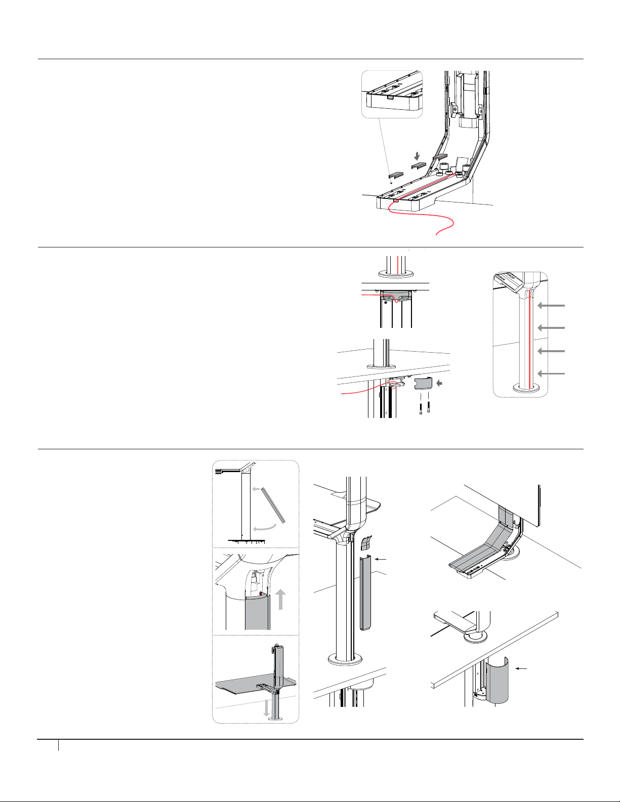
For wired keyboard and mouse, break away the tab in the front of the cover
and run the cable through the channel and secure with cable cover. Follow
the rest of the cables down the colomn.
Step 11
Snap cable covers in place.
1.
2.
Keyboard and Mouse Cables
• For wired keyboard and mouse, break away the tab
in the front of the cover and run the cable through
the channel and secure with cable cover. Follow the
rest of the cables down the column.
STEP 10 (FOR SINGLE/DUAL MONITOR)
Cable Routing
• With the keyboard tray at its highest position, route all cables
through the cable holder as shown here and exit the
cables to the side closer to the power and CPU.
• There should be no cable slack. Lock the cables
in position with the cable cover and secure it with 2 screws.
*Bundle all cables in 4 areas shown in the image with zip-tie.
STEP 11 (FOR SINGLE/DUAL MONITOR)
Snap All Cable Covers in Place
Click
1.
2.
The end with
2 screws is top.
Click
Orient the part
so the tab is
on the upper
side.
6
Page 7
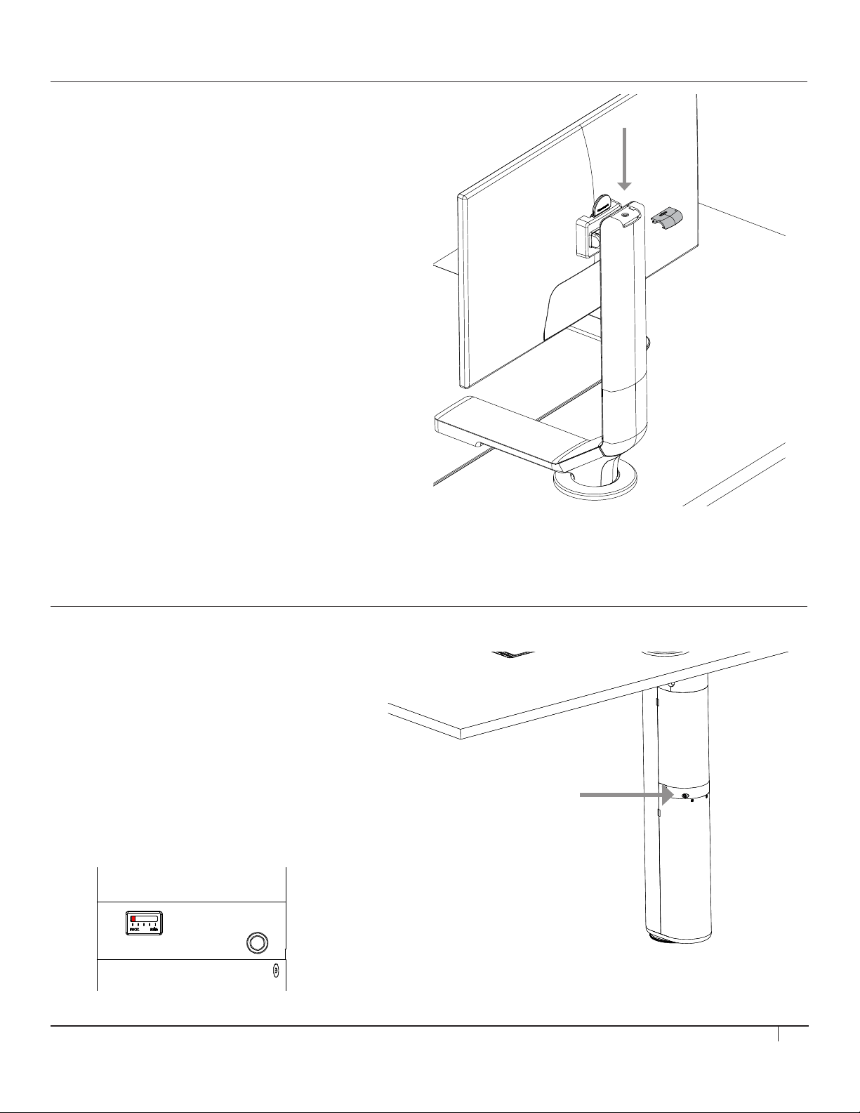
STEP 12 (FOR SINGLE/DUAL MONITOR)
Step 12
Remove the cap on the top of the monitor stand and adjust
monitor height using a 6mm allen wrench.
Set the height of the monitor so the top of the screen comes
to the users eye level.
Step 13
Using a 6mm hex tool, turn the adjuster screw to adjust the counter balance
system.
Suggestion on the adjustment.
Min: 5lbs monitor
Mid: 20lbs monitor
Max: 30lbs monitor
Adjust Monitor Height
• Remove the cap on the top of the monitor stand
and adjust monitor height using a 6mm allen wrench.
• Set the height of the monitor so the top of the
screen comes to the user's eye level.
STEP 13 (FOR SINGLE/DUAL MONITOR)
Adjusting the Counterbalance
• Using a 3mm hex tool, turn the adjuster screw
to adjust the counterbalance system.
NOTE - DO NOT USE POWER TOOL AS IT
MAY DAMAGE THE PRODUCT
Suggestion on the adjustment.
Min: 5lbs monitor
Mid: 20lbs monitor
Max: 30lbs monitor
7
Page 8
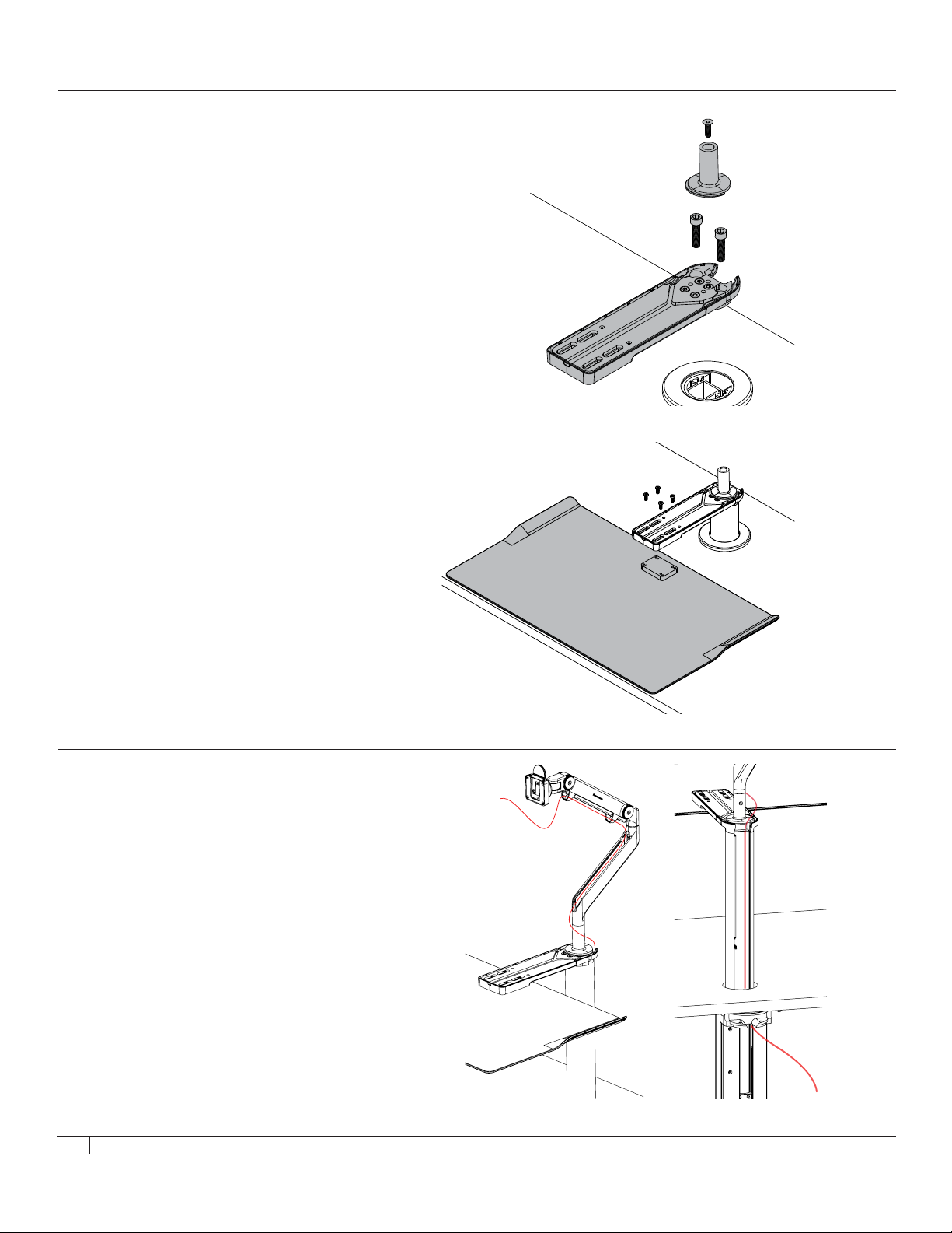
STEP 6 (FOR M2, M8 OR M/FLEX)
Step 6
Next install keyboard tray
Step 6
Next install keyboard tray
Step 7
Raise the keyboard tray to the highest position.
Run the monitor cables down the monitor arm/ mex and through the rear
opening. Secure cables in the clips .
Run down the channel of the column and through the grommet.
* keeping the cables organized and lined up in the channel will help the installation of the
cable cover.
Step 7a
For wired keyboard and mouse, break away the tab in the front of the cover
and run the cable through the channel and secure with cable cover. Follow
the rest of the cables down the colomn.
Attach Arm Mount
• Move to top of desk and install the open
architecture mount to the column.
• Then install M2 / M8 / M/ Flex onto the mount.
• Refer to the user manual for installation of the monitor arm.
STEP 7 (FOR M2, M8 OR M/FLEX)
Install Keyboard Tray
• Place the keyboard tray on the work surface
and attach using 4 screws.
STEP 8A (FOR M2, M8 OR M/FLEX)
Install Monitor Cables
• Raise the keyboard tray to the highest position.
• Run the monitor cables down the monitor arm
and through the rear opening.
• Secure cables in the clips.
• Run down the channel of the column and
through the grommet.
* Keeping the cables organized and
lined up in the channel will help the
installation of the cable cover.
8
Page 9
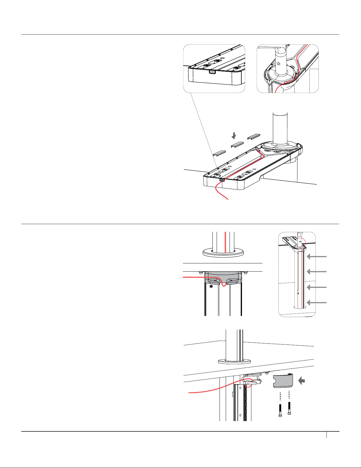
STEP 8B (FOR M2, M8 OR M/FLEX)
Step 7a
For wired keyboard and mouse, break away the tab in the front of the cover
and run the cable through the channel and secure with cable cover. Follow
the rest of the cables down the colomn.
Step 8
Keyboard tray at its highest position, route all cables through the cable
holder as shown here and exit the cables to the side closer to the power and
CPU. There should be no cable slack. Lock the cables in position with the
cable cover.
*When using USB cables, bundle all cables in 4 areas shown in the image.
Step 9
Attach the Vesa plate to your monitor and Install monitor on monitor arm.
Install Keyboard Cables
• For wired keyboard and mouse, break away the tab in
the front of the cover and run the cable through the
channel and secure with cable cover. Follow the rest
of the cables down the column.
STEP 9 (FOR M2, M8 OR M/FLEX)
Cable Routing
• With the keyboard tray at its highest position, route
all cables through the cable holder as shown here and
exit the cables to the side closer to the power and CPU.
There should be no cable slack. Lock the cables in
position with the cable cover.
* When using USB cables, bundle all cables in
the 4 areas shown in the image.
9
Page 10
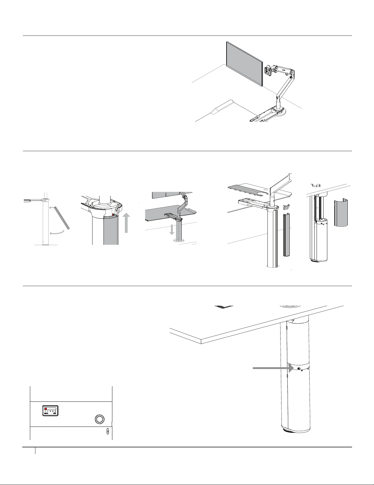
STEP 10 (FOR M2, M8 OR M/FLEX)
Step 9
Attach the Vesa plate to your monitor and Install monitor on monitor arm.
1.
Step 10
Snap cable covers in place.
1.
Step 11
Using a 6mm hex tool, turn the adjuster screw to adjust the counter balance
system.
Step 10
Snap cable covers in place.
1.
1.
2.
Step 11
Using a 6mm hex tool, turn the adjuster screw to adjust the counter balance
system.
Suggestion on the adjustment.
Min: 5lbs monitor
Mid: 20lbs monitor
Step 10
Snap cable covers in place.
1.
2.
1.
2.
Click
Step 11
Using a 6mm hex tool, turn the adjuster screw to adjust the counter balance
system.
Suggestion on the adjustment.
Min: 5lbs monitor
Mid: 20lbs monitor
Max: 30lbs monitor
1.
Step 11
Using a 6mm hex tool, turn the adjuster screw to adjust the counter balance
system.
1.
2.
Step 11
Using a 6mm hex tool, turn the adjuster screw to adjust the counter balance
system.
Suggestion on the adjustment.
Min: 5lbs monitor
Mid: 20lbs monitor
Max: 30lbs monitor
Attach Monitor
• Attach the VESA plate to your monitor
and install monitor on monitor arm.
STEP 11 (FOR M2, M8 OR M/FLEX)
Snap All Cable Covers in Place.
1.
2.
STEP 12 (FOR M2, M8 OR M/FLEX)
Adjusting the Counterbalance
• Using a 3mm hex tool, turn the adjuster screw
to adjust the counterbalance system.
NOTE - DO NOT USE POWER TOOL AS IT
MAY DAMAGE THE PRODUCT
Suggestion on the adjustment.
Min: 5lbs monitor
Mid: 20lbs monitor
Max: 30lbs monitor
Click
Click
10
Page 11
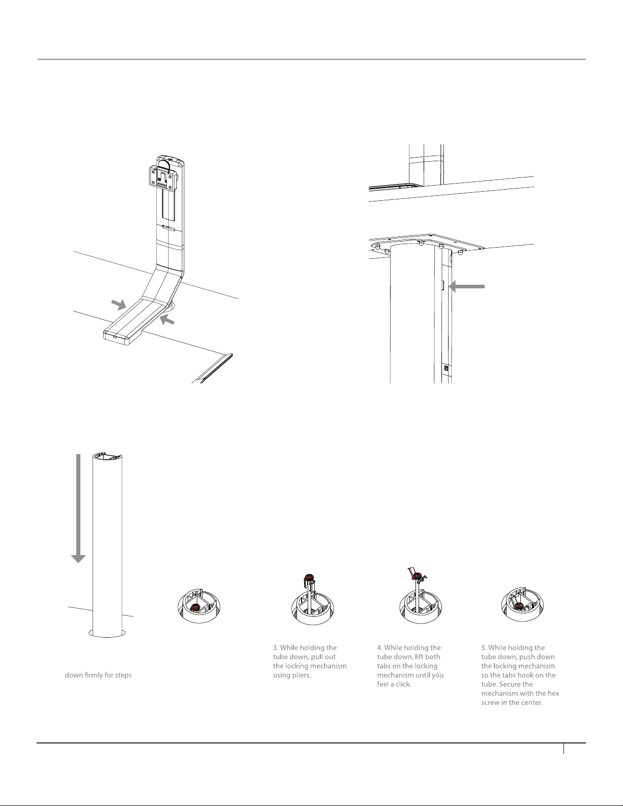
TIPS FOR UNINSTALLATION
Removing plastic cover (cable cover)
Place a plastic sheet on the tab shown in the image and strike it with a
hammer.
*
You may damage the plastic tab if you use a athead screw driver.
Removing plastic cover (cable cover)
Place a plastic sheet on the tab shown in the image and strike it with a
hammer.
*
You may damage the plastic tab if you use a athead screw driver.
Locking down the tube
Removing Plastic Cover (Monitor Stand)
To remove the plastic covers, pull up on the area shown in the image.
Removing Plastic Cover (Cable Cover)
Place a plastic sheet on the tab shown in the image and
strike it with a hammer.
* You may damage the plastic tab if you use a flathead screw driver.
Locking Down the Tube
1.Push the tube all
the way down and
continue holding it
2-5.
2. While holding the
tube down, look for the
locking mechanism (red
colored).
11
Page 12
HSQSUDIREV1
 Loading...