

Page 1

INSTALLATION INSTRUCTIONS
Page 2
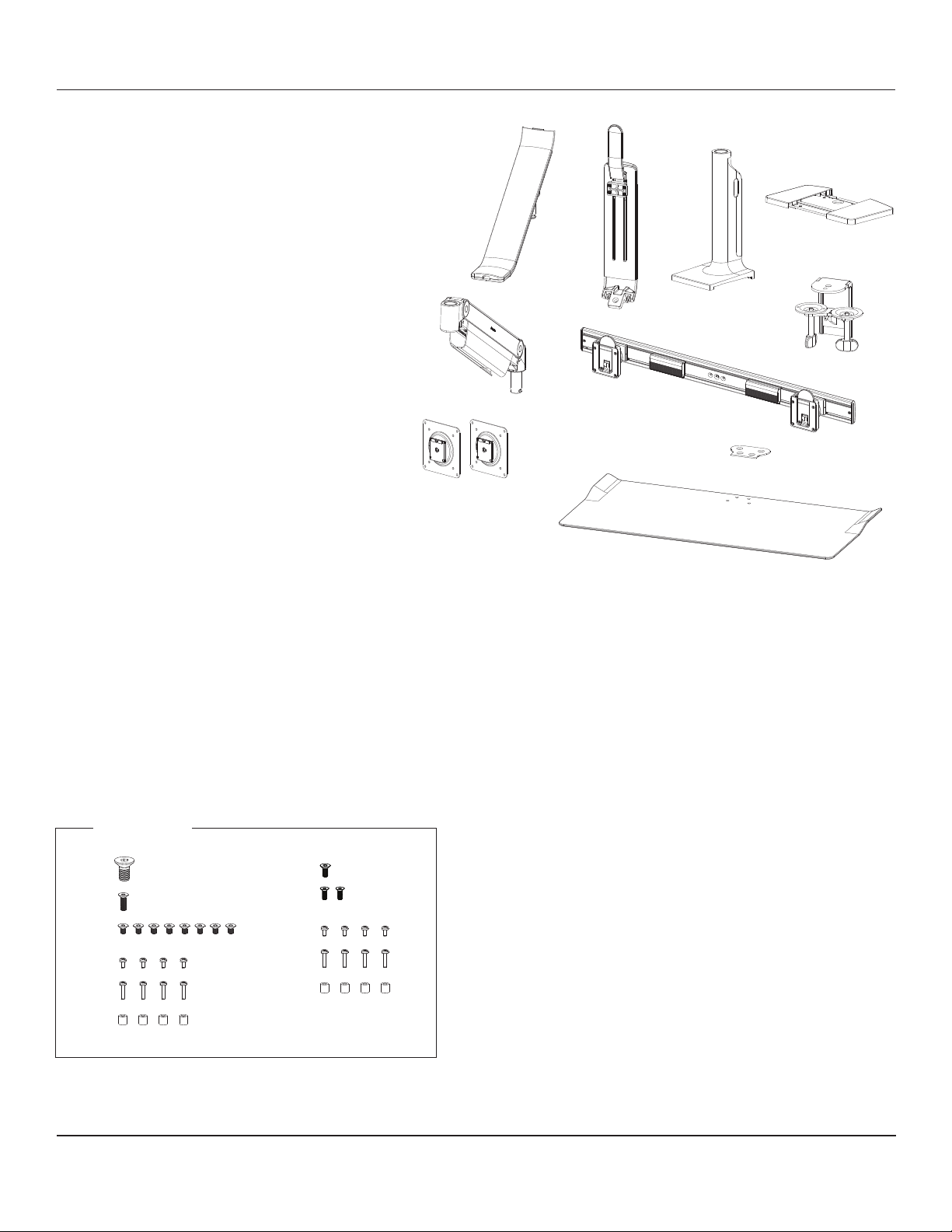
PARTS REQUIRED
Single QuickStand Lite Parts
A (1) Lower Arm
B (1) Upper Arm
C (1) Base
D (1) Base Plate
E (1) M8 Dynamic Arm Long
F (1) Clamp Bracket
G (1) VESA Plate
H (1) Keyboard Platform
I (1) Keyboard Platform Mounting Plate
J (1) M12 x 25mm Flat Head Machine Screw
K (1) M6 x 20mm Flat Head Machine Screw
L (8) M6 x 10mm Flat Head Machine Screw
M (4) M4 x 8mm Pan Head Phillips
N (4) M4 x 18mm Pan Head Phillips
O (4) VESA Spacers
G
Additional Parts for Dual Monitor QuickStand Lite
P (1) Crossbar
Q (1) VESA Plate
R (1) M6 x 14mm Flat Head Machine Screw
S (2) M5 x 14mm Flat Head Machine Screw
T (4) M4 x 8mm Pan Head Phillips
U (4) M4 x 18mm Pan Head Phillips
V (4) VESA Spacers
A
E
B
C
D
F
P
Q
I
H
Hardware
J R
K
L T
M U
N V
O
Customer Service: N America +1 800 400 0625 / International +353 (0)1 858 0910
S
www.humanscale.com
Page 3
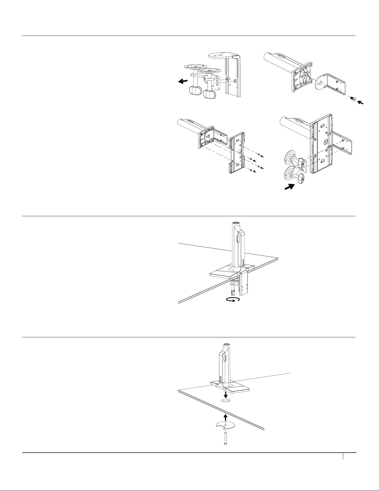
STEP 1 (IF USING CLAMP MOUNT)
Assemble Base and Clamp
• Loosen the two M6 x 12mm screws on the clamp
bracket and remove the clamp foot assembly (fig. A)
• Attach the clamp bracket to the base using the
M12 x 25mm countersink screw (fig. B)
• Attach the base plate to the base with four
M6 x 10mm countersink screws (fig. C)
• Slide the clamp foot assembly back onto the clamp
bracket and tighten the two M6 x 12mm screws (fig. D)
A
C
STEP 2 (IF USING CLAMP MOUNT)
B
D
Attach Base to Table
• Slide the assembled base onto the desk and
tighten the clamp feet. If needed, move the clamp
feet to the lower position on the bracket.
• Proceed to STEP 3
STEP 1 (IF USING BOLT MOUNT)
Attach Base to Table
• Position the QuickStand Lite base over the work surface hole.
• Align the bolt-through plate, foam side up, under the
work surface. Pass the bolt through the hole in the plate
and screw into the QuickStand Lite base.
• Full tighten until secure.
• Proceed to STEP 3
3
Page 4
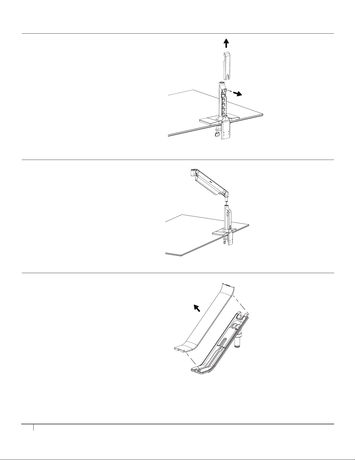
STEP 3
Remove Cable Cover
• Take off the plastic cable cover from the
base and remove the 180° stop screw.
STEP 4
Insert M8 Arm
• Place the M8 arm into the socket on the
base and re-insert the 180°stop screw.
STEP 5
Prep Lower Arm
• Remove the plastic cable cover from the lower arm.
4
Page 5
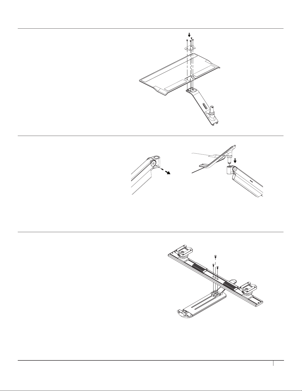
STEP 6
Attach Keyboard Platform
• Attach the keyboard platform to the lower
arm using four M6 x 10mm countersink screws
and the included metal plate.
STEP 7
Attach Lower Arm to Base
• Remove the 180° stop screw from
the M8 arm head. (fig. E)
• Place the lower arm with keyboard
platform into the M8 arm socket and
re-insert the 180° stop screw. (fig. F)
E F
STEP 8 (IF CONFIGURED WITH A CROSSBAR)
Attach Crossbar
• Attach the monitor crossbar to the upper
arm using 2 M5 x 14mm screws and one
M6 x 14mm screw.
5
Page 6
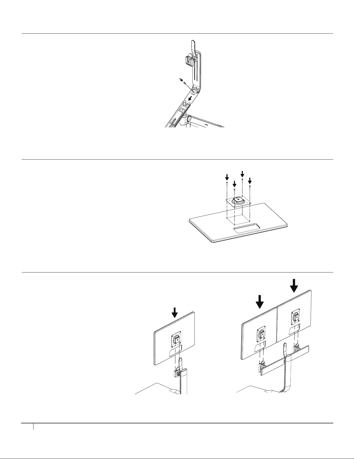
STEP 9
Attach Upper Arm
• Slide the upper arm assembly down onto the
lower arm and secure it with a M6 x 20mm
countersink screw.
STEP 10
Attach VESA Plate
• Attach the VESA plate to your monitor(s)
using four M4 x 8mm pan head screws.
If necessary, use the included plastic
spacers and extended screws.
ST EP 11
Attach Monitors
• Slide the monitor(s) onto the monitor
quick release until it snaps into place.
6
Single Monitor Dual Monitors
Page 7
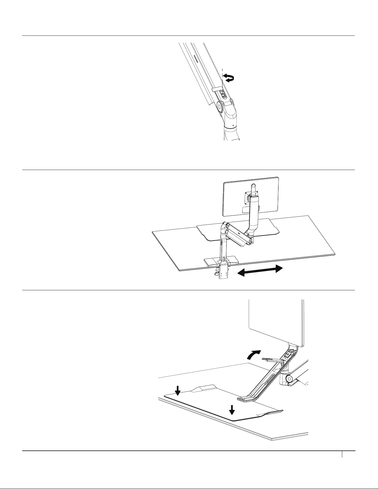
STEP 12
Adjust Monitor Arm Tension
• Adjust the tension of the M8 arm using a 5mm
hex key to match the weight of the monitor(s).
• Turn clockwise for heavier weights and
counterclockwise for lighter weights.
STEP 13
Adjust Keyboard Platform Location
• Loosen the clamp feet and reposition the base
so that the keyboard platform sits in the desired
location, then re-tighten the feet.
STEP 14
Set Keyboard Platform Angle
• Lift the release lever on the lower arm
(fig. G) and press the keyboard platform
flat against the desk surface.
• Press to the lever back down tightly
to lock the platform angle.
7
Page 8
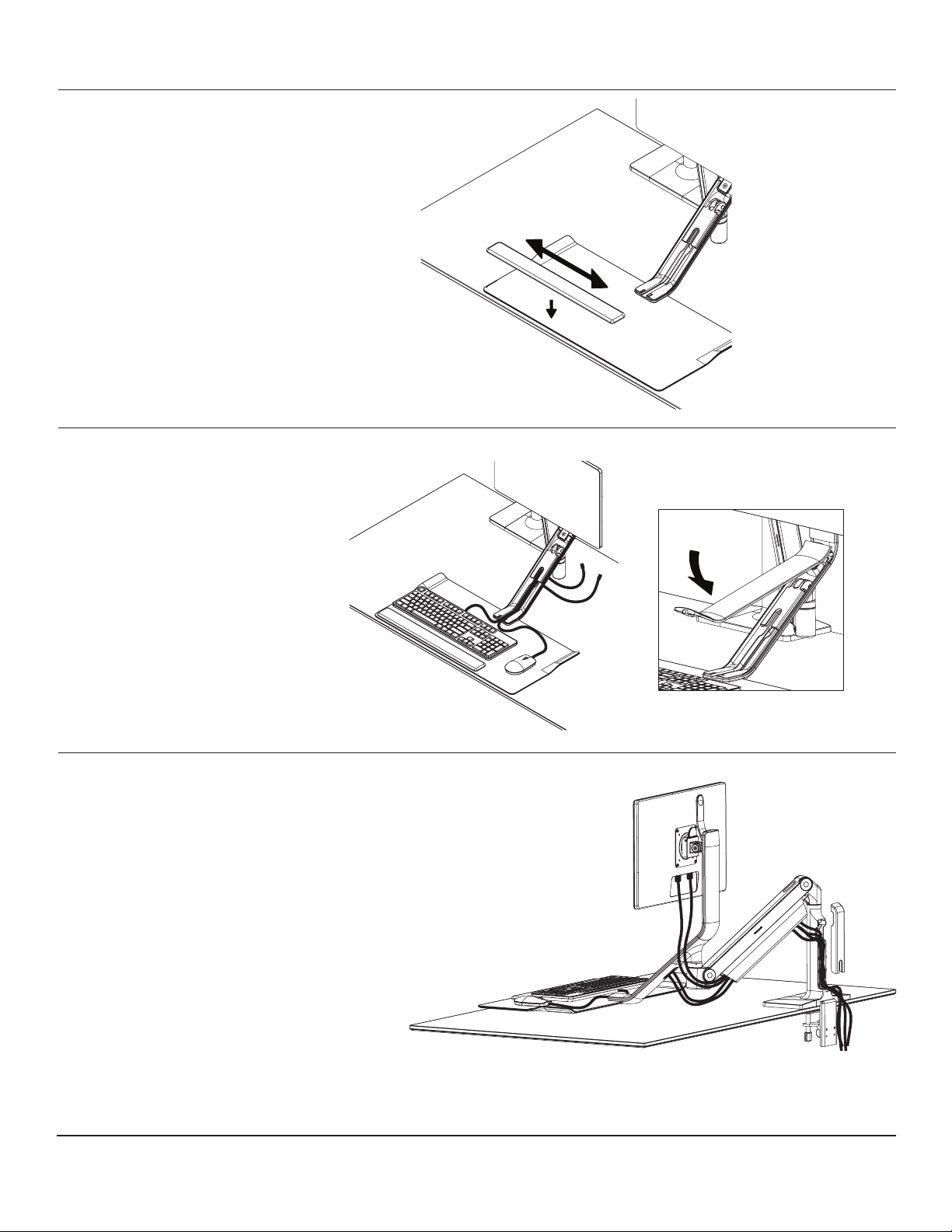
STEP 15
Attach Palm Rest
• Position the palm rest where desired,
then remove the plastic backing and
press down to adhere.
STEP 16
Setup Cable Management
• Place the keyboard and mouse on the
platform and run the cables through
the center channel on the arm and
through the cable hole.
• Attach the lower arm cover (fig. H)
by hooking the edge under the upper
arm cover and pressing the rest
down until it snaps tight.
STEP 17
Connect Monitors
• Run the power and video cable through the M8 arm
cable channel (fig. I) one at a time, followed by the mouse
and keyboard cables.
• Guide the cables through the side opening and
down the back, then replace the cover (fig. J) by pressing
it over them and slide down to lock it in place again.
H
J
Customer Service: N America +1 800 400 0625 / International +353 (0)1 858 0910
I
HSQSLI0216_INTENG
www.humanscale.com
 Loading...