

Page 1

USER GUIDE
Page 2

Table of Contents
PARTS REQUIRED 3
IDENTIFYING COMPONENTS 4
INSTALLING M/POWER BASE 6
ATTACHING A MONITOR ARM 8
ELECTRICAL SPECIFICATIONS 10
Page 3
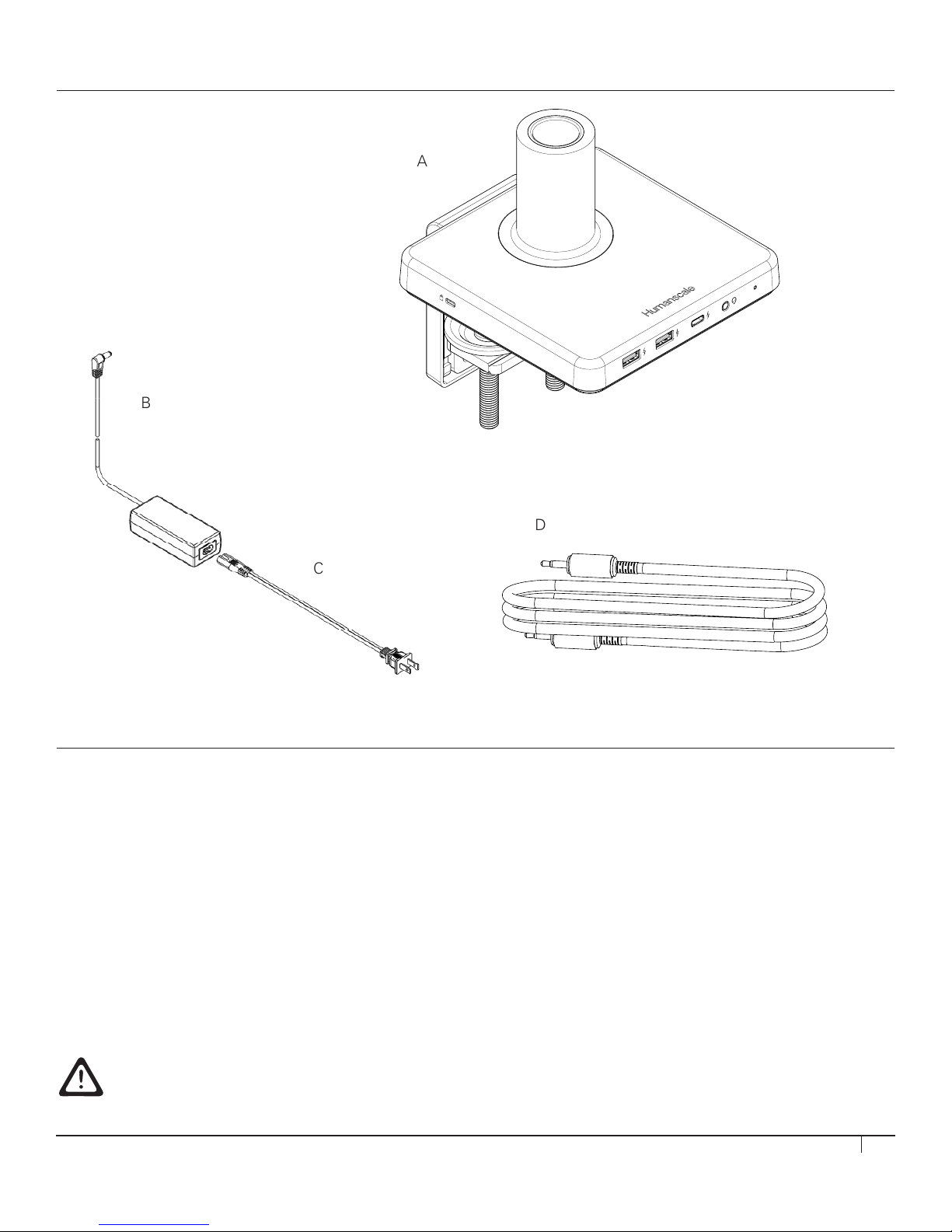
A
B
C
D
3
D
PARTS REQUIRED
M/Power Parts
A (1) M/Power Hub and Clamp
B (1) Power Adaptor
C (1) Power Cable (localized)
D (1) TRSS Combo Jack Cable 1.8 m
Humanscale Part Number 813-xxxx
INSTALLAION GUIDELINES
This product is intended to be used with Humanscale's Moniotor Arm product line
and the following office desk styles placed on a non-skid surface:
1. Systems Furniture with panel hung surfaces
2. Systems Furniture with a floor mounted panel behind the desk
3. Systems Furniture with a desk mounted panel in the rear of the desk
4. Back-to-back desks sharing the same frame
When mounting monitor arm and monitor(s) with this product on a freestanding desk/table:
1. The freestanding desk/table should have base that is no less than 30” deep and 66.5” wide
2. The freestanding desk/table should be a minimum of 200 lbs and placed on a non-skid surface.
3. The tabletop thickness should be no less than 1.2 inches and strong enough to support a minimum weight load of 165lb.
CAUTION: DO NOT rotate monitor past rear edge of desk. Doing so can create
an unstable situation and may cause equipment damage or personal injury.
3
Page 4
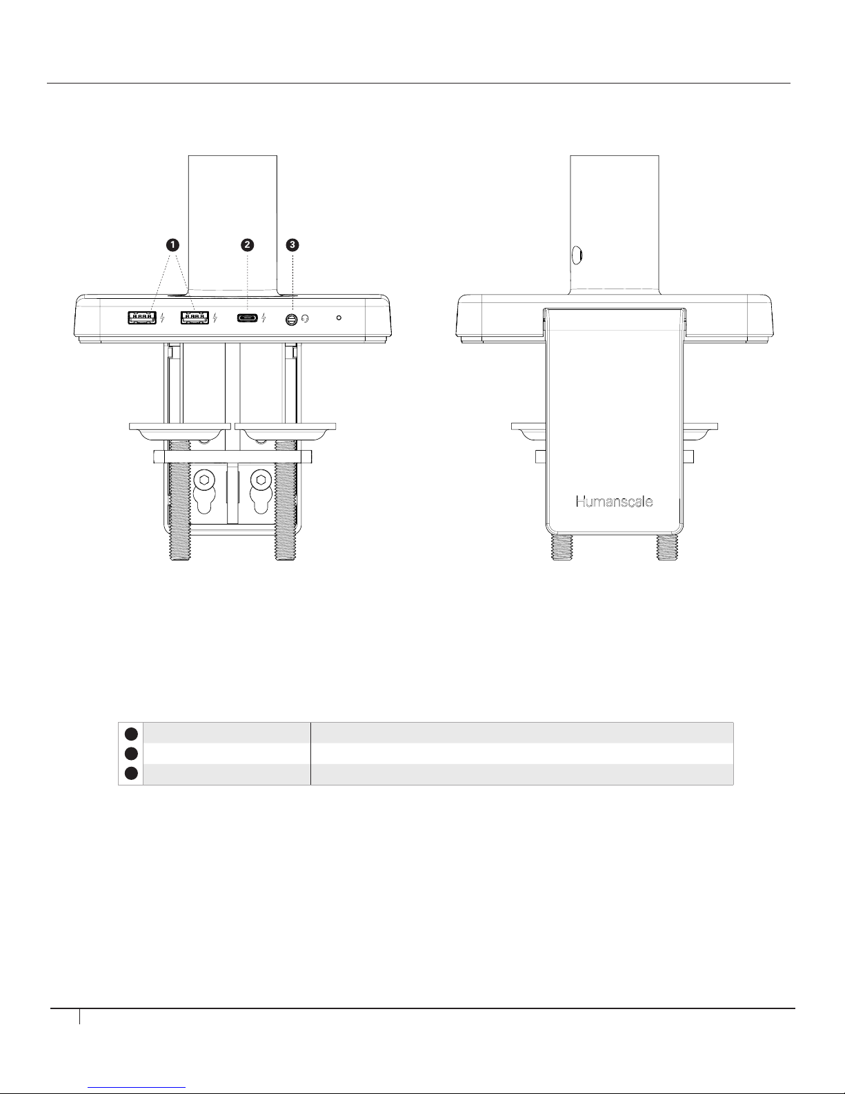
1 2 3
IDENTIFYING COMPONENTS
IDENTIFYING COMPONENTS
Front Panel
Component Description
1
USB A charging port Supports charging 5V, 2.4Amax
2
USB Type-C charging port Supports charging 5V, 3Amax
3
3.5 mm TRRS jack To connect combined headphone and microphone headset
Rear Panel
4
Page 5
IDENTIFYING COMPONENTS
IDENTIFYING COMPONENTS
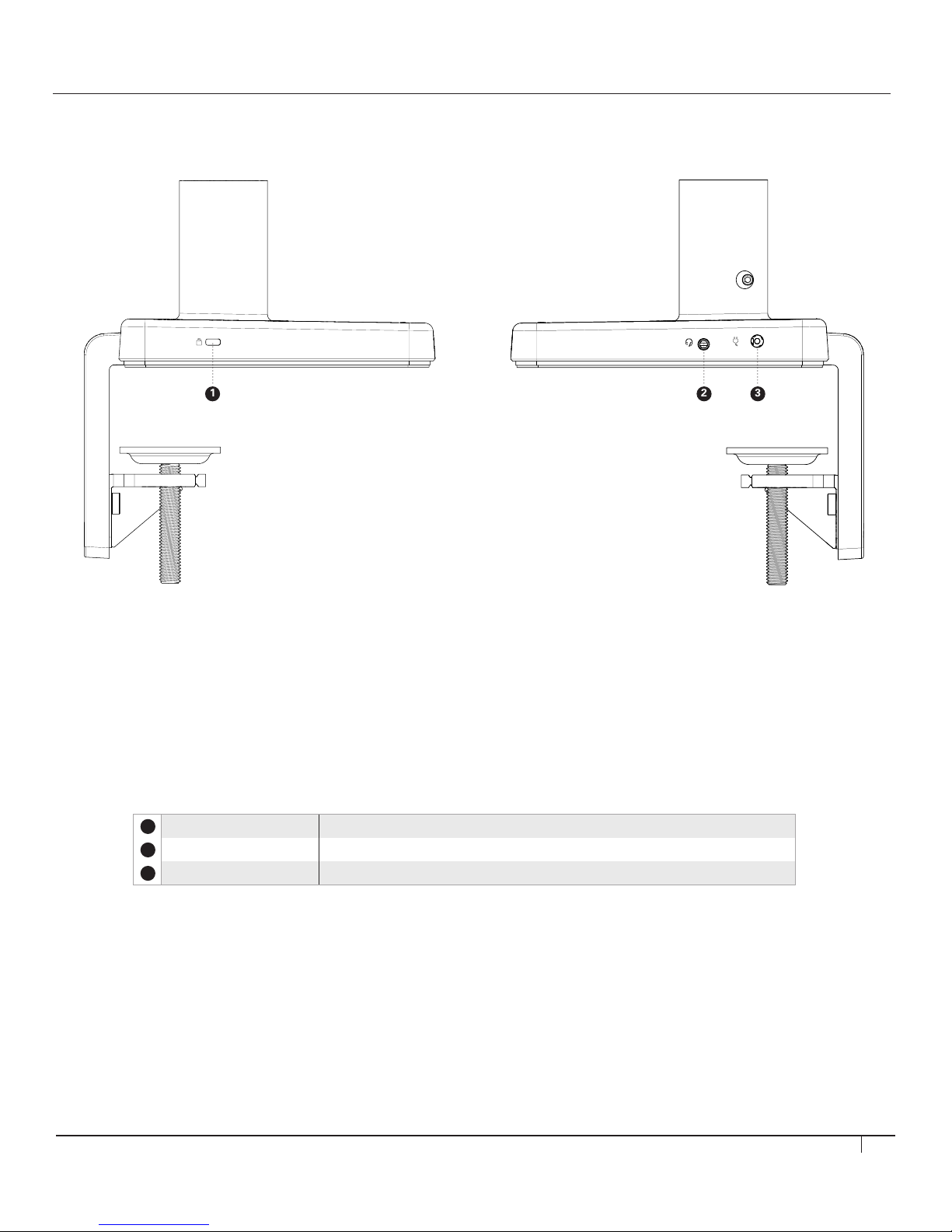
2 3
1
Left Panel Right Panel
Component Description
1
Kensington Slot To secure unit from theft
2
3.5 mm TRRS jack To connect auxiliary audio cable out
3
DC in 19V / 2.21A DC to power M/Power
5
Page 6
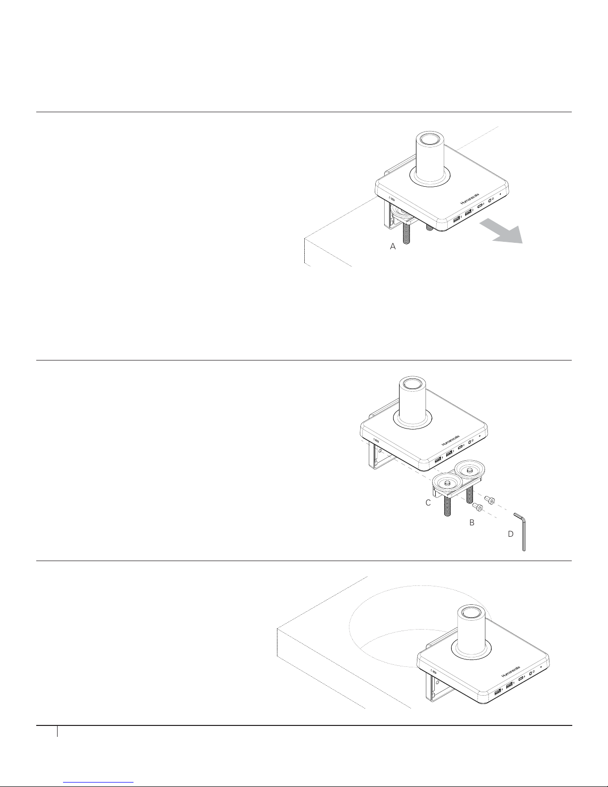
INSTALLING M/POWER ONTO EDGE OF TABLE
C
B
D
A
M8: 40 lbs.
Do NOT exceed maximum weightload limits.
A
C
B
D
Caution: Maximum weight load of M/Power is as follows:
STEP 1
Place M/Power Clamp onto Table
• Slide mount against work surface edge and
fully tighten clamp screw (fig. A)
M2.1: 15.5 lbs. M8.1: 28 lbs. M10: 40 lbs. M/Flex: 60 lbs. Total.
M10 is not to be used on M/Flex when mounted to M/Power
Do NOT exceed maximum weight limits.
When used in conjunction with M/Power, M/Flex post must be limited to 24 inches
INSTALLING M/POWER THROUGH
A GROMMET HOLE OR SYSTEM FURNITURE
STEP 1
Disassemble Clamp
• Remove the two screws (fig. B) using 4 mm hex key (fig. D) and detach
the smaller clamp bracket (fig. C) from the larger bracket
STEP 2
Place into Grommet Hole or System Furniture Gap
• Place the L Bracket of the M/Power through
the grommet hole and to the desired position
Note: Minimum hole diameter is 3" (76 mm)
6
Page 7
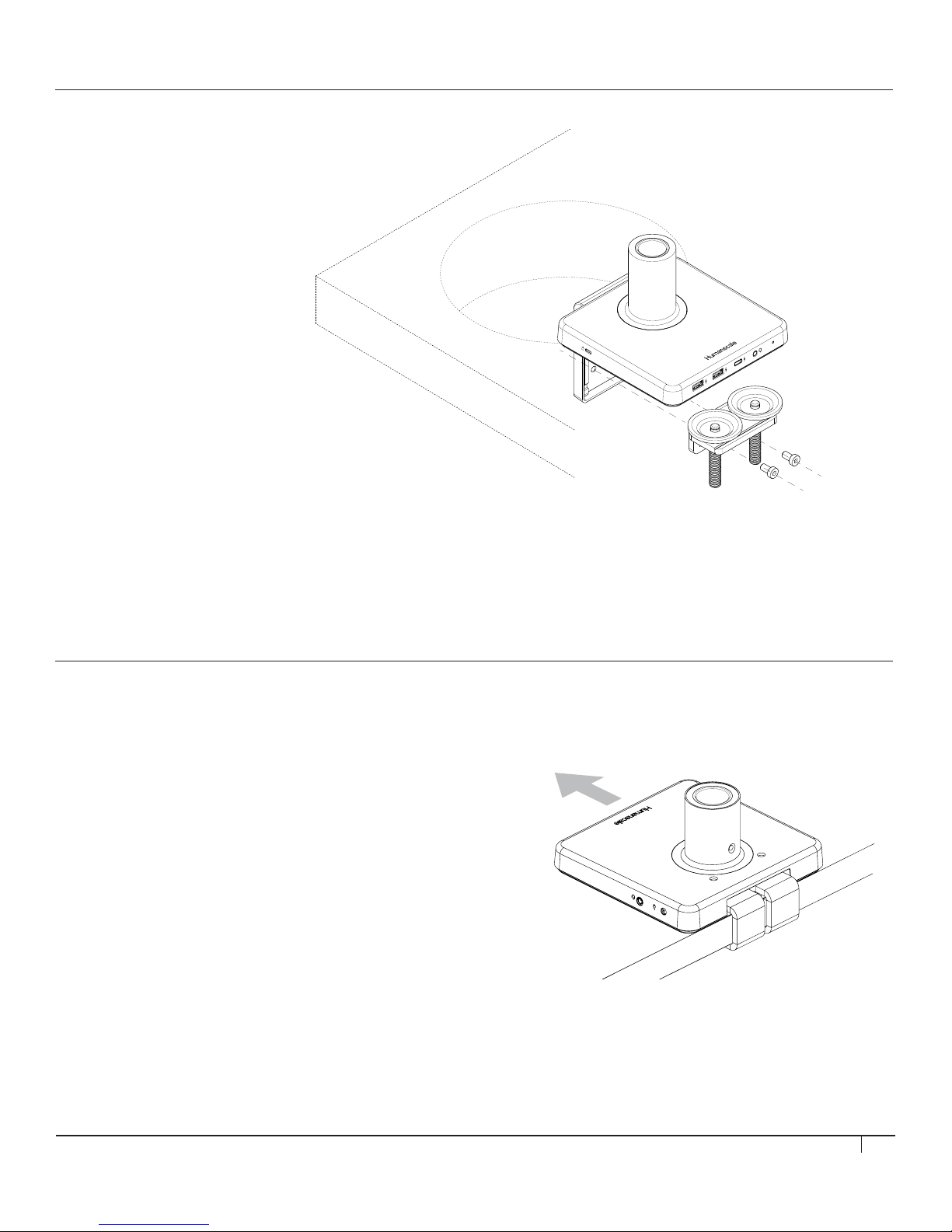
STEP 3
Reattach Clamps
• Secure the lower bracket to the larger bracket reusing the two M6 screws (g. E)
STEP 3
Reattach Clamps
• Secure the lower bracket to the larger
bracket reusing the two M6 screws (fig. E)
E
INSTALLING M/POWER ONTO SLIDING DESK
STEP 1
Place M/Power Clamp onto table edge
• Slide unit with loosely mounted bracket against work surface edge
7
Page 8
A
G
H
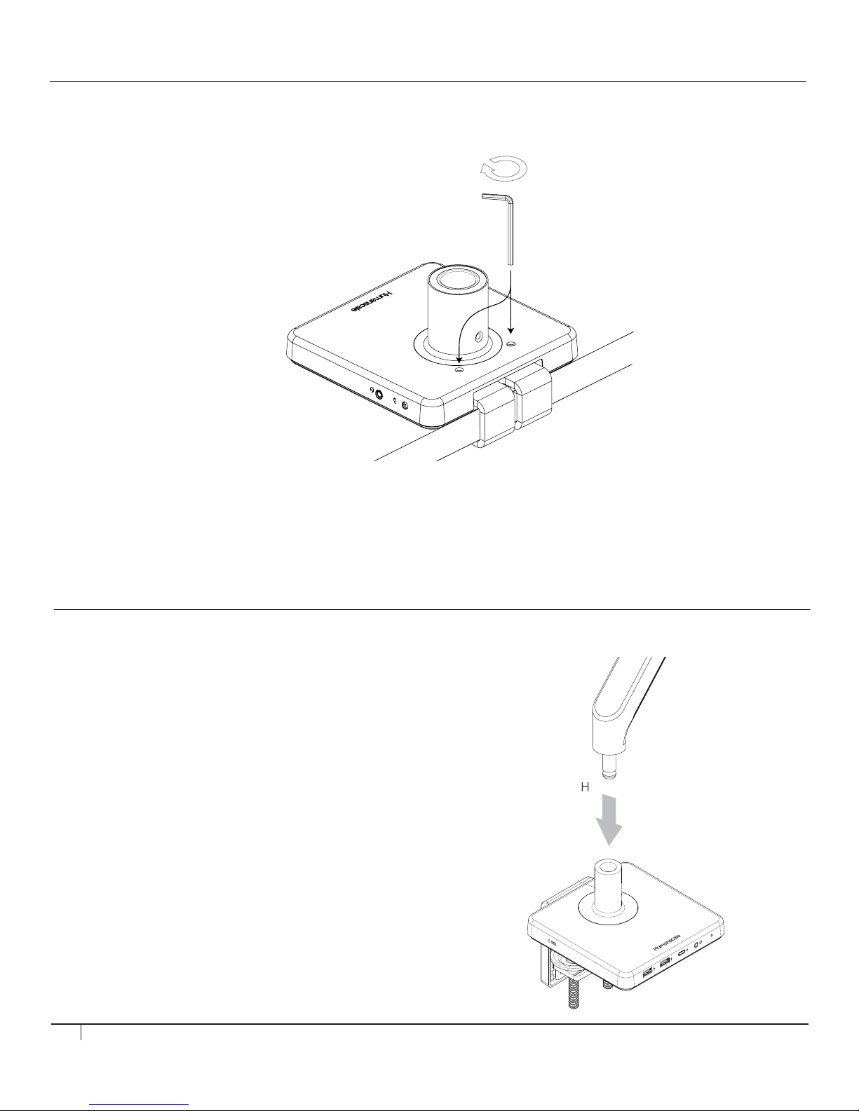
STEP 2
Tighten Clamp
• Tighten both set screws into bracket to a snug fit (fig. F)
F
ATTACHING A MONITOR ARM TO M/POWER
M2.1/M8.1 MONITOR ARM
Adjust Base Clamp for Correct Work Surface Depth
• Insert Monitor Arm into the Base stem (fig. H) until you hear it click into place
• Proceed to the "Attach VESA Bracket to Monitor" step
in the main M2.1 or M8.1 instruction guide
8
Page 9
J
I
K
J
I
K
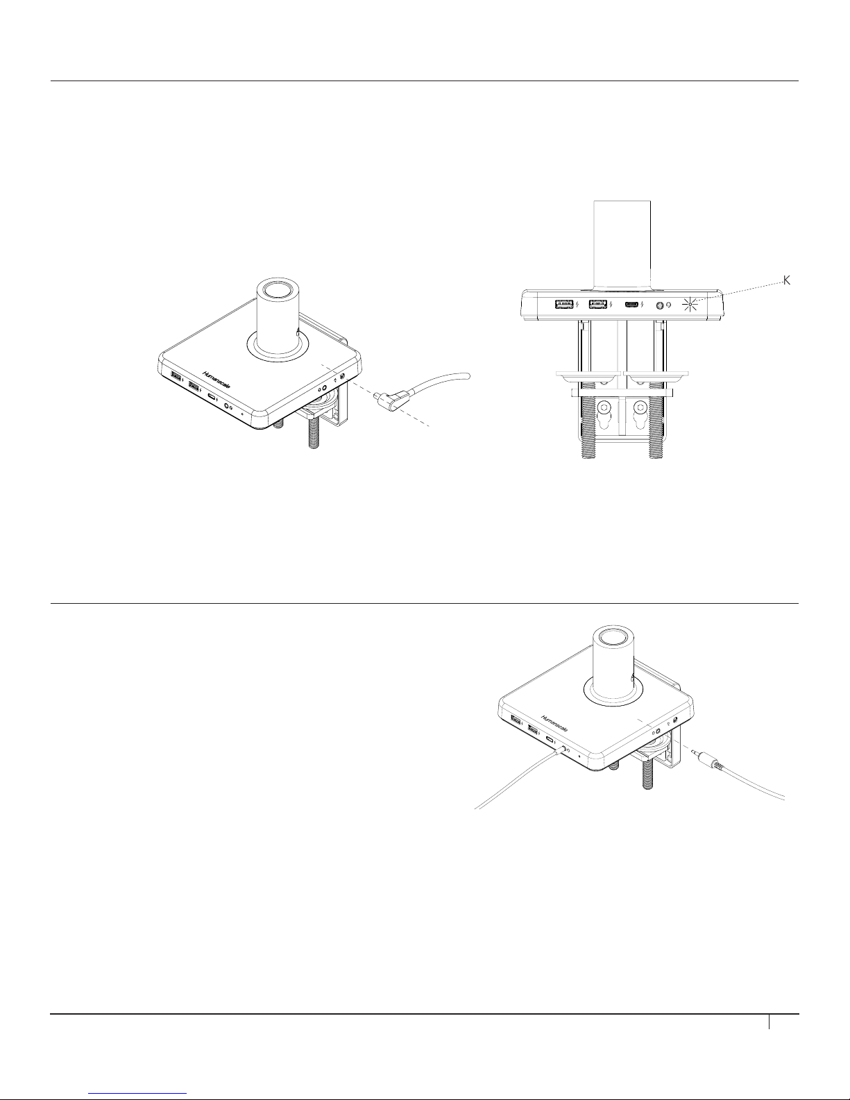
STEP 3
Plug in power cable
• Insert power cable into rearward power jack
• LED light (fig. K) will illuminate to indicate power
Do not use this AC Adapter
for other purposes than for
its original intented usage
with M/Power
STEP 4
Connect auxiliary cable for audio pass through
• Insert auxiliary audio cable into rearward audio jack, connect to computer
• Insert headphones into front audio jack
9
Page 10
ELECTRICAL SPECIFICATIONS
Ports
Power Consumption No load 86mW
Environmental Temperature - Operating 0°C to 40°C
USB - A (x2)
USB - C (x1) Supports USB-C native power delivery of 5, 3Amax
Audio Pass Through Jack (x2) 4-pole3.5mm combo jack
DC (x1) Accepts 19V DC input
Full load 42W
Temperature - Storage -20°C to 60°C
Relative Humidity - Operating 20% to 80% (non-condensing)
Relative Humidity - Storage 5% to 90% (non-condensing)
Supports BC1.2, Chinese standard YW/T1591-2009. Divider mode voltage on D+
D- lines, 5V, 2.4Amax
FCC Notice
M/ Power Models MP-AXY (where X and Y can be alphanumeric or blank)
This device complies with part 15 of the FCC Rules. Operation is subject to the following two conditions: (1) This device may
not cause harmful interference, and (2) this device must accept any interference received, including interference that may cause
undesired operation.
Note: This equipment has been tested and found to comply with the limits for a Class B digital device, pursuant to part 15 of the
FCC Rules. These limits are designed to provide reasonable protection against harmful interference in a residential installation. This
equipment generates, uses and can radiate radio frequency energy and, if not installed and used in accordance with the instructions,
may cause harmful interference to radio communications. However, there is no guarantee that interference will not occur in a
particular installation. If this equipment does cause harmful interference to radio or television reception, which can be determined by
turning the equipment off and on, the user is encouraged to try to correct the interference by one or more of the following measures:
—Reorient or relocate the receiving antenna.
—Increase the separation between the equipment and receiver.
—Connect the equipment into an outlet on a circuit different from that to which the receiver is connected.
—Consult the dealer or an experienced radio/TV technician for help.
The FCC requires the user be cautioned that any changes or modifications made to this device that are not expressly approved by
Humanscale may void the user's authority to operate the equipment.
Humanscale
1114 Avenue of the Americas
New York, NY 10036
+1 (800) 400-0625
Innovation, Science and Economic Development Canada ICES-003 Compliance Notice:
CAN ICES-3 (B)/NMB-3(B)
10
 Loading...