

Humanscale M/Connect MCM8B, M/Connect MCM8BT, M/Connect MCM8ST, M/Connect MCM8WT, M/Connect MCM2BT User Manual
...Page 1

M/CONNECT
USER GUIDE
Page 2

Table of Contents
PARTS REQUIRED 3
IDENTIFYING COMPONENTS 4
INSTALLING M/CONNECT SOFTWARE 6
INSTALLING M/CONNECT BASE 7
ATTACHING A MONITOR ARM 8
INSTALLING THE CABLE CHANNELS 10
CONNECTING MONITORS 11
USING M/CONNECT 12
TROUBLESHOOTING 13
PRODUCT SPECIFICATIONS 14
ELECTRICAL SPECIFICATIONS 15
Page 3

PARTS REQUIRED
M/Connect Parts
A (1) M/Connect Hub and Dock Clamp
B (2) Cable Channels (Provided if ordered in configuration)
C (1) USB 3.0 Upstream Cable
D (1) Power Adaptor
E (1) Power Cable (localized)
A
B
C D
E
3
Page 4

IDENTIFYING COMPONENTS
1 2 3
4
Front Panel
Component Description
3.5 mm TRRS jack To connect combined headphone and microphone headset
1
USB 3.0 port To connect USB devices (USB 1.0, 1.1, 2.0, 3.0 compatible)
2
USB 3.0 port To connect USB devices (USB 1.0, 1.1, 2.0, 3.0 compatible)
3
4
DC in 5V / 8A DC to power M/Connect
Rear Panel
4
Page 5

IDENTIFYING COMPONENTS
4 5
1
Left Panel Right Panel
Component Description
1
Gigabit Ethernet port To connect to local area network
2
DisplayPort port To connect an DisplayPort monitor
3
HDMI Port To connect an HDMI monitor
4
USB 3.0 upstream port To connect a notebook / computer
5
USB 3.0 port with
battery-charging
function
6
USB 3.0 port To connect USB devices (USB 1.0, 1.1, 2.0, 3.0 compatible)
7
USB 3.0 port To connect USB devices (USB 1.0, 1.1, 2.0, 3.0 compatible)
8
USB 3.0 port with
battery-charging function
To connect USB devices (USB 1.0, 1.1, 2.0, 3.0 compatible). USB port is
compatible for quick-charging BC1.2 compatible devices
To connect USB devices (USB 1.0, 1.1, 2.0, 3.0 compatible). USB port is
compatible for quick-charging BC1.2 compatible devices
62 73 8
5
Page 6

INSTALLING M/CONNECT SOFTWARE
STEP 1
M/Connect Driver Installation Instructions
YOU MUST INSTALL THE NECESSARY DRIVERS ONTO YOUR COMPUTER BEFORE
USING M/CONNECT. THIS WILL ENSURE PROPER OPERATION.
NOTE: For proper installation of the DisplayLink drivers, it is important to make sure your
USB 3.0 Host Controller Driver and Graphics Adapter Driver are up to date
• Go to http://www.displaylink.com/downloads/
• Choose your operating system
• Download and install the latest driver
• Ready to go!
TROUBLESHOOTING
We recommend following these guidelines as a best practice.
Ensure installation isn’t blocked by a corporate firewall
If your firewall blocks the installation of this driver, corporate users should contact their systems administrator and have them allow
this driver under their corporate installation standard procedures (MSI Installer), available for download from DisplayLink’s website.
Individual users should ensure that suggestions to update other drivers are followed. This typically includes updating the laptop
graphics and USB drivers to the latest version.
Updating the host graphics drivers to the latest version: For Windows 7, USB laptop drivers are provided by Intel/ OEM notebook
vendors. Users have to update this manually. Please refer to http://support.displaylink.com for more details. For Windows 8 onwards,
laptop drivers are provided by Microsoft and updated in the system via Windows update.
For the best user experience, we recommend running the latest version of the driver.
6
Page 7
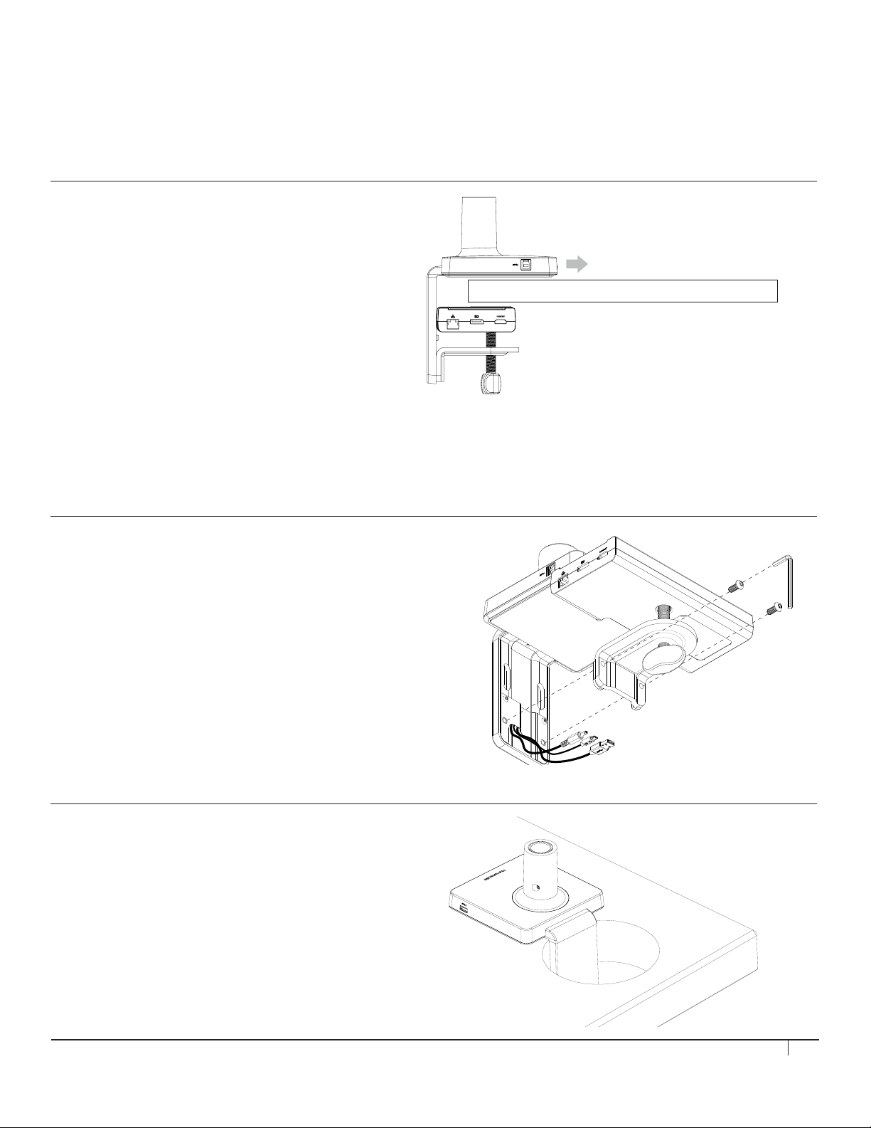
INSTALLING M/CONNECT ONTO EDGE OF TABLE
Caution: Maximum weightload of M/Connect is as follows: M2: 20 lbs
M8 and M/Flex: 40 lbs.
Do NOT exceed maximum weightload limits.
STEP 1
Place M/Connect Clamp onto Table
• Slide mount against work surface edge and
fully tighten clamp screw (fig. A)
A
INSTALLING M/CONNECT THROUGH A GROMMET HOLE
OR SYSTEM FURNITURE
STEP 1
Disassemble Clamp
• Remove the two screws (fig. B) using hex key (fig. D) and detach
the three cables from the Dock (fig. C) to separate Dock from Hub
STEP 2
Place into Grommet Hole or System Furniture Gap
• Place the Hub of the M/Connect through
the grommet hole and to the desired position
Note: Minimum hole diameter is 3" (76 mm)
B
C
D
7
Page 8
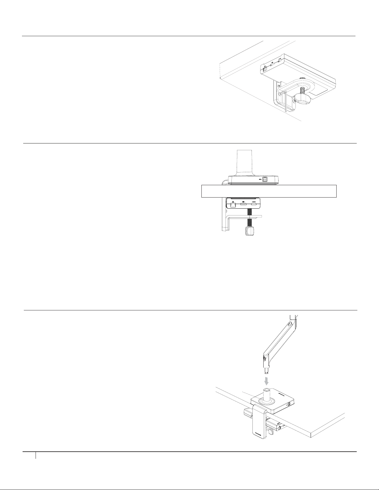
STEP 3
Reattach Dock to Hub
• Reattach all three cables to the Dock and into their appropriate ports
• Secure the Dock to the Hub reusing the two screws (fig. E)
STEP 4
Tighten Clamp Screw
• Tighten the clamp screw (fig. F) to ensure the M/Connect
is secured to the work surface, by rotating the knob 3 full
turns after initial resistance is felt
E
F
ATTACHING A MONITOR ARM TO M/CONNECT
M2 MONITOR ARM
Adjust Base Clamp for Correct Work Surface Depth
• Remove set screw (fig. G ) from Base using hex key
• Insert Monitor Arm into the Base stem (fig. H) with its slot facing the rear
• Reinsert the set screw and tighten so that the arm is unable to lift out
and the 180º stop* is engaged
(*arm won't be able to swivel past the rear desk edge)
• Proceed to the "Attach VESA Bracket to Monitor" step
in the main M2 instruction guide
G
H
8
Page 9
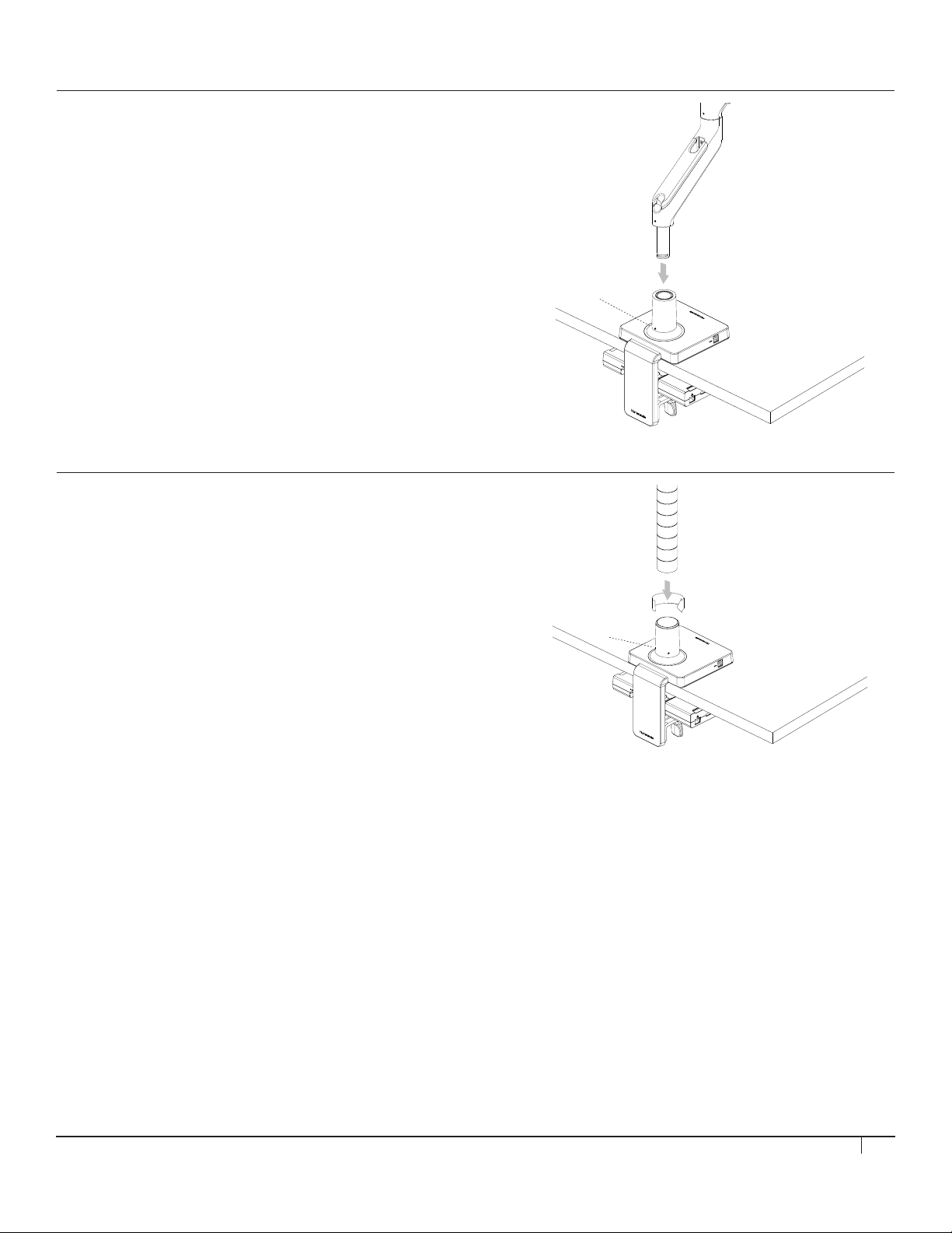
M8 MONITOR ARM
Adjust Base Clamp for Correct Work Surface Depth
• Remove set screw (fig. I ) from Base using hex key
• Insert Monitor Arm into the Base stem (fig. J) with its slot facing the rear
• Reinsert the set screw and tighten until it seats
and the 180º stop* is engaged
(*arm won't be able to swivel past the rear desk edge)
• Proceed to the "Attach VESA Bracket to Monitor" step
in the main M8 instruction guide
M/FLEX MONITOR ARM POST
Adjust Base Clamp for Correct Work Surface Depth
I
J
• Remove the two set screws (fig. K) from Base using hex key
• Place M/Flex post into Base stem
• Screw in the post (fig. L) until it is connected firmly
• Proceed to the "Cable Management and Bracket Assembly"
section the main M/Flex instruction guide
• Reinsert the two set screws and tighten so that the post
is unable to rotate easily
L
K
9
Page 10
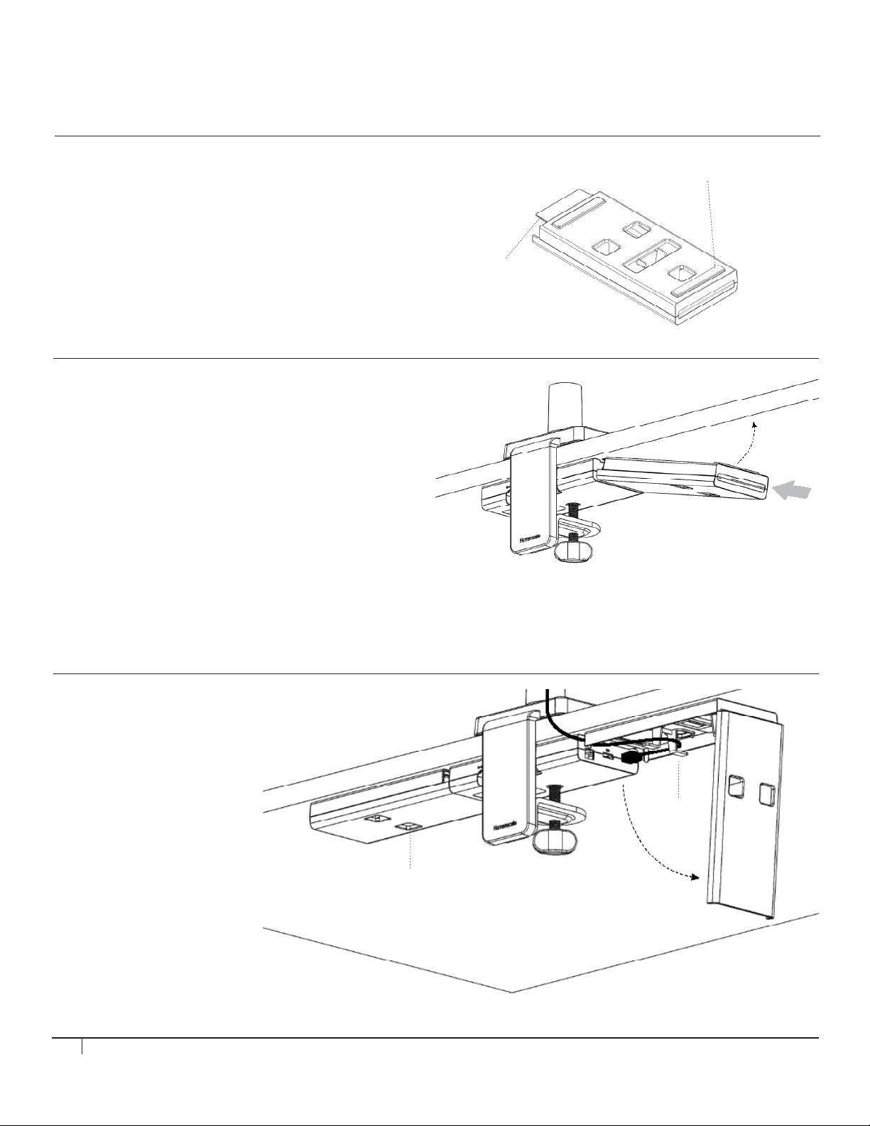
INSTALLING THE CABLE CHANNELS
STEP 1
Remove Adhesive Backing
• Peel off the Velcro’s protective backing (fig. M)
STEP 2
Attach to M/Connect Dock
• Approach M /Connect Dock on an angle to make
sure the adhesive does not stick to the desk before
the Cable Channel is aligned
• Align Cable Channel with Dock using the alignment tab
• Push up Cable Channel against the bottom of the
work surface to secure it with adhesive
• Repeat Steps 1 and 2 with the second Cable Channel
M
Alignment Tab
2
1
STEP 3
Connect Cables
• Open up Cable Channel by reaching into
bottom Access Holes and squeezing
the opening tabs together
• Plug cables into the Dock
• Coil the cable slack around
the 4 hook features
• Close Cable Channel until it snaps
10
Hook
Features
Access
Holes
Page 11
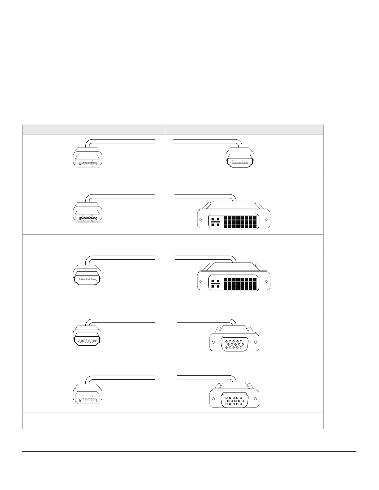
CONNECTING MONITORS TO M/CONNECT
The M/Connect Dock provides two monitor connections: an HDMI port and a DisplayPort (DP) port.
Each of your monitors has one or more of the following ports: VGA, DVI, HDMI or DP. If the monitor has an HDMI or DP port, you
can use the existing cable to plug directly into the same port on the M/Connect Dock. If you have two monitors and each has an
HDMI and a DP, then you can plug one into each of the same ports on the M/Connect Dock. However, if you do not have one of
these configurations ( i.e. you only have VGA or DVI monitor ports), you will need to use a replacement cable to provide the correct
connection from the M /Connect Dock to your monitor.
Humanscale offers replacement cables, found in the M/ Connect Price List and in the M/ Connect section of the
Humanscale website: www.humanscale.com.
Use the chart below to determine which replacement cable you need based on your monitor's port availability:
Available port on M/Connect (output) Available port on monitor (input)
M/Connect Replacement Cable - DP to HDMI
Humanscale part # : CA-DPHD
M/Connect Replacement Cable - DisplayPort to DVI
Humanscale part # : CA-DPDV
M/Connect Replacement Cable - HDMI to DVI
Humanscale part # : CA-HDDV
M/Connect Replacement Cable - HDMI to VGA
Humanscale part # : CA-HDVG
M/Connect Replacement Cable - DP to VGA
Humanscale part # : CA-DPVG
11
Page 12

Set the Monitor Input Source
• Each Monitor has a menu (often in the front right lower corner) in which you can select the cable input that you are using.
• Set the correct input by using the scroll keys to select the correct source.
• Many monitors have more than one of the same connector (example, HDMI 1 and HDMI 2). Make sure to note the specific port
where you installed the cable to ensure you have the exact port you are using entered into the monitor (if you connect to HDMI 1,
you must select HDMI1). If you select the wrong one, the monitor will NOT work.
• Some monitors detect the input source automatically and may not require setting.
USING M/CONNECT
BEFORE YOU CONNECT M/CONNECT TO YOUR LAPTOP:
• Please install the necessary drivers as detailed on page 6
• Please make sure your monitor(s) are set up properly to display from
the inputs you are using (e.g. HDMI 1, HDMI 2, DisplayPort etc.)
STEP 1
Power up M/Connect
• Plug the 5V DC jack into M/ Connect, and then plug power adapter (pg. 3, fig. D) into the mains ( pg. 3, fig. E) to power it up
STEP 2
Connect M/Connect to your Laptop
• Connect your laptop using the USB 3.0 cable provided. It may take a few seconds for your laptop to recognize the additional
screen(s). While the connection is being made, the screens will flash
STEP 3
Adjust Screen Positions
• To adjust the 'position' of your screens relative to your mouse movement, go to:
- Windows: Control Panel \ Appearance and Personalization \ Display \ Screen Resolution
- Mac: Apple menu \ System Preferences \ Displays
• Drag and drop the display icons into the correct locations and save settings. Moving windows or the mouse
between the screens should be a seamless intuitive experience once the monitor locations are set
STEP 4
Attaching Peripherals
• Plug your non-portable peripherals (e.g. printers) into M/ Connect’s under-work surface Dock
STEP 5
Ready to use!
• You are now ready to begin using your M/ Connect
12
Page 13

TROUBLESHOOTING
If the screens don’t light up and show data after first installing:
• First, check that the input selected on the monitor(s) matches the cable types used in connection (DVI/HDMI etc). It can be
best practice to set this to the desired connection rather than auto
• Check that the cables are correctly installed and pushed firmly into place on both the monitor and into the Dock connection
on M/Connect
• Ensure that the monitor is powered on. You should see lights on the monitor which means it has power
• Ensure M/Connect is powered on. You should see a white light on the front of the Hub which means it has power
• Try unplugging the USB cable connected to the host notebook and then reconnect after a few seconds. If the connection is made
correctly, the host notebook or computer screen should flash while the solution configures the external displays. Configuration
can then be viewed under Windows Display Manager
DO YOU HAVE ANY QUESTIONS REGARDING INSTALLATION?
Please visit: http://support.displaylink.com / or call Humanscale Tech Support: 800-400 - 0625
13
Page 14
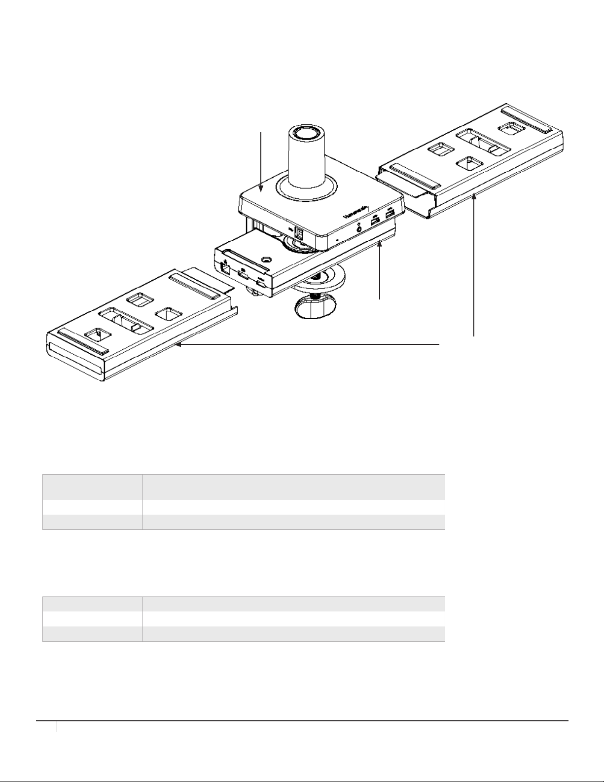
PRODUCT SPECIFICATIONS
Hub
Dock
Product Weight
M/Connect
(Hub and Dock)
Cable Channel
Power Adapter Darfon Adapter 274g
2.1kg (excluding Cable Channel and Power Adapter)
2 x 310g
Power Consumption (Dual head, no other USB devices connected)
Notebook Hibernate
Notebook Sleep
Notebook On
0.9W
1.5W
3.4W
Cable Channels
14
Page 15
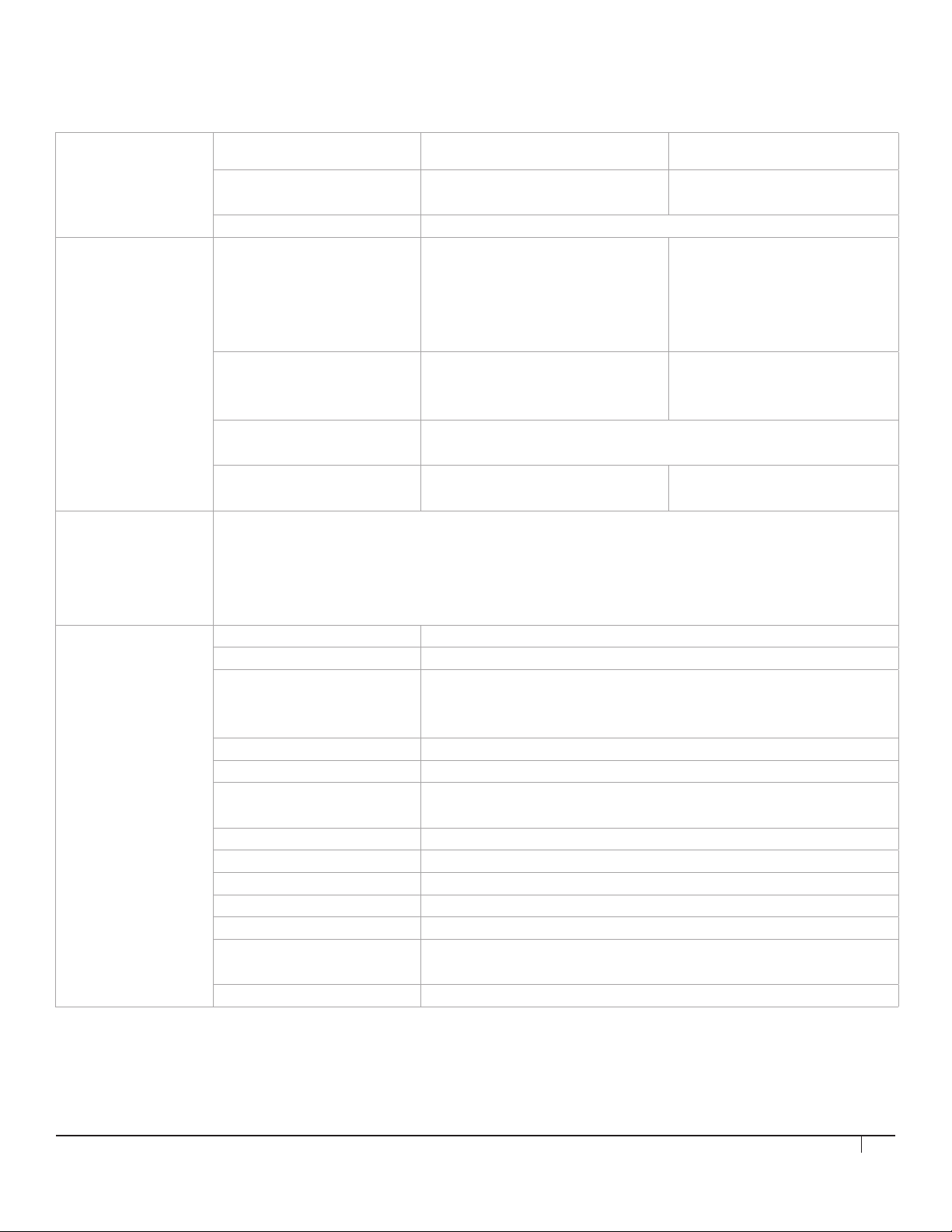
ELECTRICAL SPECIFICATIONS
Hub USB 3.0 ports
Dock Video 1 output Display Port 1.2, Dual mode Max resolution 2560x1440 (16:9) single
Operating System Windows 7/7Pro (32bit/64bit),
Power Adapter
Requirement
(self powered)
Microphone/Headphone 4-pole 3.5mm combo jack with auto switch Apple/Samsung type versus Nokia type
Video 2 output HDMI 1.3 Max resolution 2560x1440 (16:9) single
Network Gigabit Ethernet
USB3.0 ports Downstream Connector Type A 1x BC1.2 (1.5A rear)
Windows 8/8.1Pro (32bit/64bit),
Windows 10 (32bit/64bit),
Apple OS X Version 10.8.3 and above
(Mountain Lion v10.8, Mavericks v10.9, Yosemite v10.10)
AC input 90 - 264V (47-63Hz)
Input connector IEC320 C8
Output connector DC 5V Single pin Barrel plug
Output DC cable length 0.8m
Output voltage and current 5V, 0~8A
Efficiency Meet US DoE level VI, efficiency >86.1%, No load power <0.1W for Darfon power
ESD IEC61000-4-2 Contact +/-4kV, Non contact +/-8kv
EFT IEC61000-4-4 +/-1kV on AC power line
Surge IEC61000-4-5 +/-1kv common/differential mode
Leakage current Leakage current <250uA at 264VAC, fulfills NFPA99
AC mainscord Length=1.8m, Plug type; 2-pin with countries reference below
Countries USA, Canada, Europe, UK, Australia, New Zealand, Japan, South Korea, India, Malay-
Audible noise No audible noise at different power level and mains voltage from 0.5m
Upstream Connector Type B 1x (connects to Notebook)
Downstream Connector Type A 1x BC1.2 (1.5A front left)
Type A 2x (5V, 0.9A)
head, auto downscale to 1920x1080
with dual head.
Supports HDMI output with passive
cable adapter
head, auto downscale to 1920x1080
with dual head.
Transfer rate 10/100/1000 Mbps (over LAN port)
Type A 2x
diameter 5.5x2.5 mm
length 11 mm
adapter
sia, Hong Kong, Singapore, Thailand, Taiwan, Philippines, South Africa, China
15
Page 16
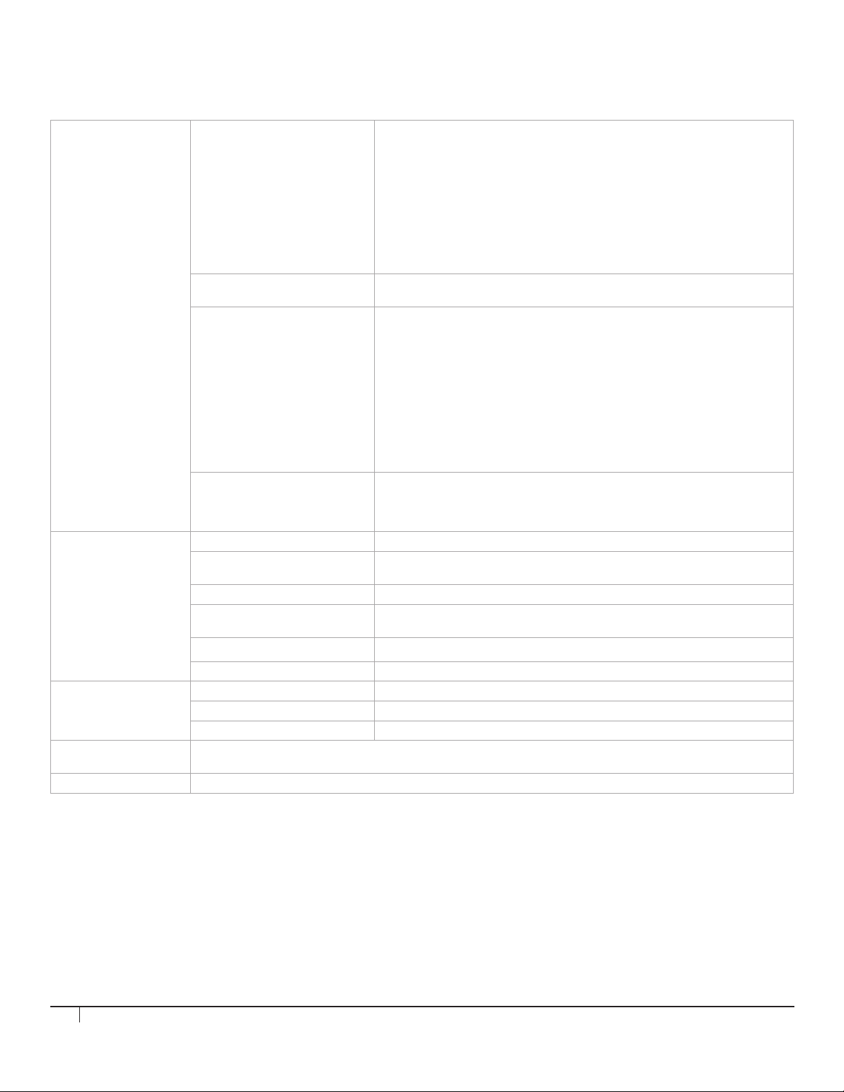
ELECTRICAL SPECIFICATIONS
Safety (based on power adapter)
and applies to complete product
Energy Efficiency Australia/NZ GEMS/MEPS 4665.1:2005+A1:2009
EMC (based on adapter and
applies to complete product)
Complete Product CE marking
Environmental Temperature - Operating 0ºC to 40ºC
Temperature Non Operating
Relative Humidity - Operating 10% to 80% (non-condensing 5 to 35°C)
Relative Humidity Non Operating
Altitude - Operating 5000m
UL(USA) UL60950-1 2nd edition 2011-12-19
CSA C22.2 NO.60950-1-07, 2nd Edition, 2011-12
IEC60950-1 2nd edition 2005 + A1-2009+ A2-2013 and EN60950-1:2006 +
A11:2009 + A1:2010 +A12 \:2011 + A2:2013
TUV SuD GS EN60950-1:2006 + A2:2013 AfPS GS 2014:01 PAK3.1
PSE J60950(H26) - JAPAN
CCC GB9254-2008; GB4943.1-2011;GB17625.1-2012 - CHINA
PSB IEC60950-1:2005+A1:2009+A2:2013 -S'PORE
AS/NZS 60950.1:2011+A1- AUS/NEW ZEALAND
BSMI CNS14336-1(2010) and CNS13438(2005) – TAIWAN
Nrcan CAN/CSA-C381.1-08 (Nat Resources Canada)
CE mark
EN55022 : 2010+AC:2011
EN50024:2010
EN61000-3-2 : 2014-Harmonics
IEC61000-4-3:2006+A1:2007+A2:2010 RF EMI
IEC61000-4-6:2013 Conduction Disturbance
IEC61000-4-8:2009 Power Freq Magnetic Field Immunity
FCC Title 47, Part 15. Subpart B: Oct.1.2011, Class B
ANSI C63. 4-2009
ICES-003 Issue 5
VCCI V-3/2013.04 / V-4/2012.04
C-TICK AS/NZS CISPR 22:2009+A1:2010
EN55022/EN55024 or Cispr22/Cispr24
FCC Part15
ICES003 ISSUE 5 (Canada)
-20ºC to 60ºC
5% to 90% (non-condensing -20 to 60°C)
Altitude - Non Operating 5000m
M/Connect Power
Consumption
Environmental Data • This product is in compliance with the Restrictions of Hazardous Substances (RoHS2) directive – 2011/65/EU.
Accessories Included USB 3.0 Cable, 1.0m, AC Power Cable 1.8m, AC Power Adapter
Notebook Hibernate 0.9W
Notebook Sleep 1.5W
Notebook On 3.4W
• This product is designed to comply with the Waste Electrical and Electronic Equipment (WEEE) Directive – 2012/19/EU.
16
Page 17

FCC Notice
M/ Connect Models MCM8B, MCM8BT, MCM8ST, MCM8WT, MCM2BT, MCM2ST, MCM2WT
This device complies with part 15 of the FCC Rules. Operation is subject to the following two conditions: (1) This device may
not cause harmful interference, and (2) this device must accept any interference received, including interference that may cause
undesired operation.
Note: This equipment has been tested and found to comply with the limits for a Class B digital device, pursuant to part 15 of the
FCC Rules. These limits are designed to provide reasonable protection against harmful interference in a residential installation. This
equipment generates, uses and can radiate radio frequency energy and, if not installed and used in accordance with the instructions,
may cause harmful interference to radio communications. However, there is no guarantee that interference will not occur in a
particular installation. If this equipment does cause harmful interference to radio or television reception, which can be determined by
turning the equipment off and on, the user is encouraged to try to correct the interference by one or more of the following measures:
—Reorient or relocate the receiving antenna.
—Increase the separation between the equipment and receiver.
—Connect the equipment into an outlet on a circuit different from that to which the receiver is connected.
—Consult the dealer or an experienced radio/TV technician for help.
The FCC requires the user be cautioned that any changes or modifications made to this device that are not expressly approved by
Humanscale may void the user's authority to operate the equipment.
Connections to this device must be made with shielded cables in order to maintain compliance with the Class B limits in the FCC
Rules and Regulations.
Humanscale
11 E26th St
New York, NY 10010
( 6 4 6 ) 3 6 7 - 5110
Innovation, Science and Economic Development Canada ICES-003 Compliance Notice:
CAN ICES-3 (B)/NMB-3(B)
HSMCI0716R2
17
 Loading...