

Page 1
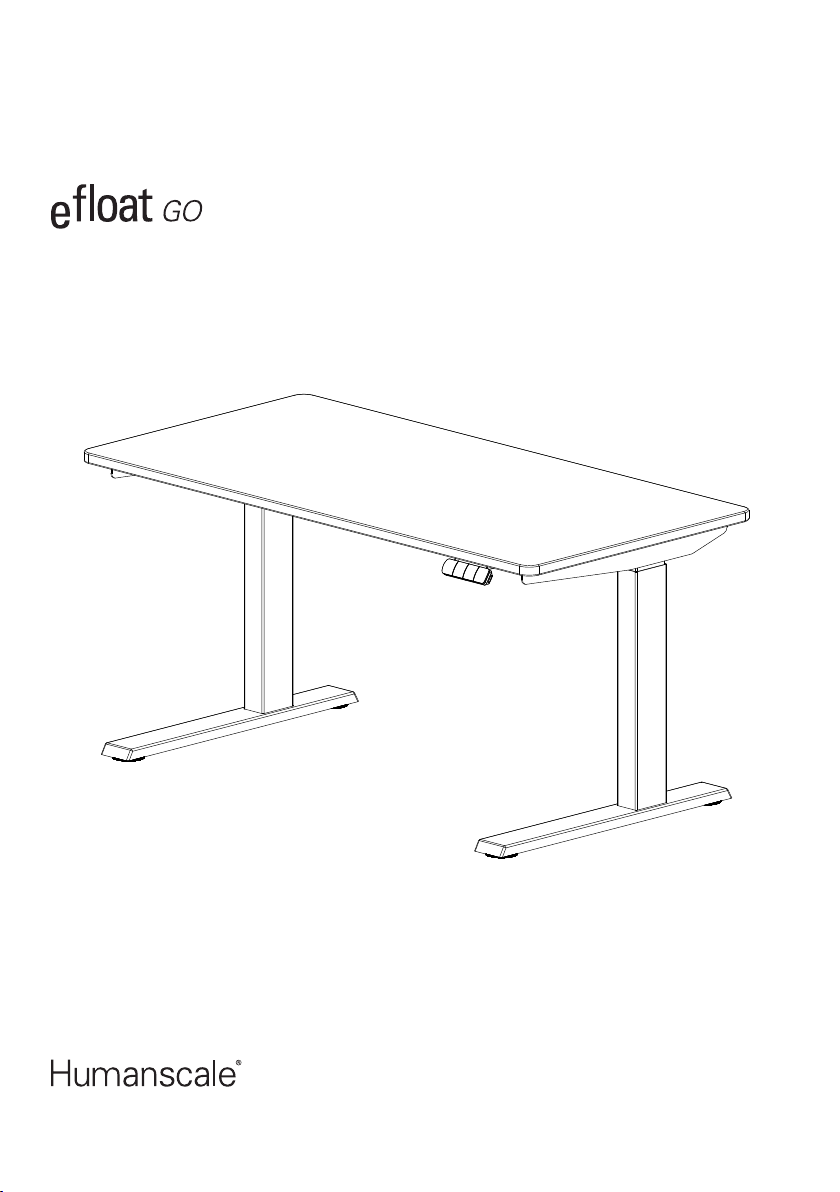
Assembly Instructions (Two-Column Kit)
North America: +1 800 400 0625
EN
1
FR 16
Page 2

Important Safety Instructions
WHEN USING AN ELECTRICAL FURNISHING, BASIC PRECAUTIONS SHOULD ALWAYS BE
FOLLOWED. READ ALL INSTRUCTIONS BEFORE USING (THIS FURNISHING). HUMANSCALE
CANNOT BE HELD LIABLE FOR INJURY OR DAMAGE CAUSED BY NON-COMPLIANCE WITH
THESE INSTRUCTIONS. SAVE THESE INSTRUCTIONS AND PASS THEM ON TO ANY FUTURE
USER.
DANGER: To reduce the risk of electric shock always unplug this furnishing from the electrical outlet
before cleaning.
WARNING: To reduce the risk of burns, fire, electric shock, or injury to persons:
• Close supervision is necessary when this furnishing is used by, or near children, invalids, or
disabled persons.
• Use this furnishing only for its intended use as described in these instructions. Do not use
attachments not recommended by the manufacturer.
• If the worksurface used with this furnishing is not of the appropriate size or shape or is not
mounted correctly to the furnishing, the assembled product could be unstable, may collapse, or
cause failure in electrical components.
• Never operate this furnishing if it has a damaged cord or plug, if it is not working properly, if it
has been dropped or damaged, or dropped into water. Return the furnishing to a service center
for examination and repair.
• Keep the cord away from heated surfaces.
• Never operate the furnishing with the air openings blocked. Keep the air openings free of lint,
hair, and the like.
• Never drop or insert any object into any opening.
• Do not use outdoors.
• Do not operate where aerosol (spray) products are being used or where oxygen is being
administered.
• To disconnect, turn all controls to the o position, then remove plug from outlet.
WARNING: Risk of Electric Shock - Connect this furnishing to a properly grounded outlet only. See
Grounding Instructions
DO NOT OVERLOAD DESK: To prevent the table from tipping or collapsing, make sure the desk is not
overloaded by the weight of the worksurface and items on table. Evenly distribute load; excess loads
near edges can reduce stability and lead to tip over.
• E Float Go - Two-Column Kit - Worksurfaces must be rectangular and at least 0.75” (20mm)
thick, depth 23"-35", width 46"-82". For stability, maximum worksurface size is 35”x 82”.
• Do not exceed maximum load including weight of worksurface of 250lbs (113kg)
• The 24” feet should be used for worksurfaces 23”-24” deep and the 30” feet should be used
for the worksurfaces 30” deep and less.
• For loading, always put heavier items in the center and distribute the load.
2
Page 3
• Do not sit or stand on table.
USE CARE WHEN OPERATING DESK:
• Before using the table check for any visible signs of damage. Do not use a damaged product.
• Make sure no obstacles are in the desk’s path and that the desk is not touching walls or
neighboring objects.
• Items taller than 20” in height should not be placed or stored under the desk.
• Keep Table Frame dry. Keep all electrical components away from water and high humidity. Do
not spray cleaning solutions directly onto table frame.
• Working Temperature for table is 5 - 40OC
• Make sure all the cords are the appropriate length to accommodate the change in height.
• Although this product comes with anti-collision function, in order to avoid any pinching, please
ensure that hands or other body parts are in a safe position during the operation.
• Unplug power cord during a thunderstorm or if you do not intend to use the desk for a long
time.
• Never use the table if it has a damaged cords or plugs.
• Keep cords away from heated surfaces.
• Over time grease might start to accumulate on the inner columns of the table legs, if this occurs
wipe columns with a soft cloth.
DO NOT OPEN ELECTRICAL COMPONENTS: Do not attempt to service the table's components.
There are no user-serviceable components within the motor control box, hand switch, or table legs. If
your table needs service or you are having issues with your table, please contact customer service.
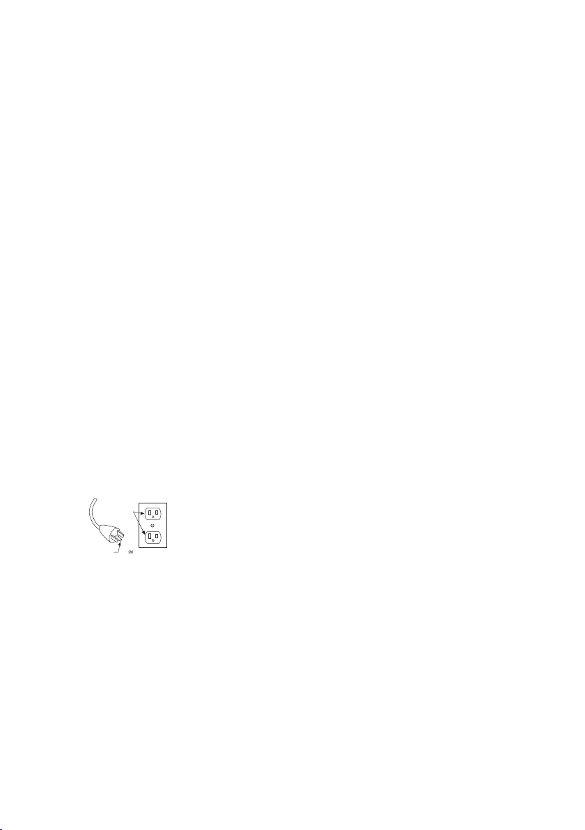
GROUNDING INSTRUCTIONS: This product is for use on a nominal 120-volt circuit and has a
grounding plug that looks like the plug illustrated below. Make sure that the product is connected to an
outlet having the same configuration as the plug. No adapter should be used with this product.
GROUNDED
OUTLET
GROUNDED
PIN
Do not modify the plug provided with the product - it will not fit the outlets, have a proper outlet
installed by a qualified electrician.
3
Page 4
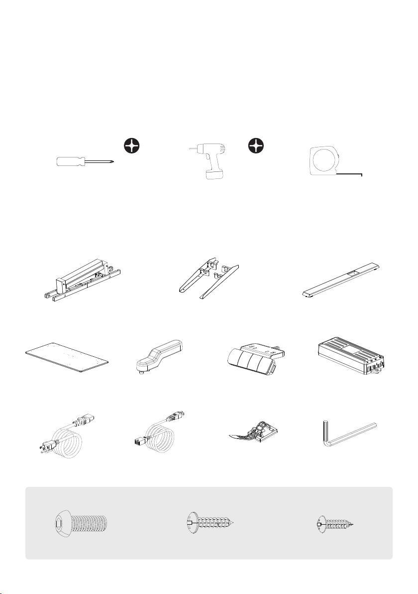
Before Getting Started
• If using a power drill, use a low torque setting.
• Do assemble product on a protective surface.
• 2 or more people may be required to maneuver the table.
• After assembly, the table will need to have an initial set up/reset performed before table can be
used.
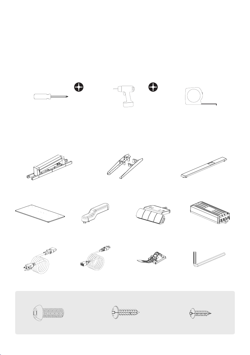
Tools Required
①
②
③
Philips Head Screw Driver
Power Drill with Philips Driver bit Measuring Tape
Parts Included
①
Leg Assembly
④ ⑦
Humanscale Worksurface
(CONFIGURATION SPECIFIC, PACKAGED
SEPARATELY)
⑧
Power Supply
⑤ ⑥
⑨
②
Left, Right Wing Brackets
Assembly Handle
Connecting Cable
③
Hand Switch
⑩ ⑪
(10) Cable Ties
(2) Feet
Control Box
4mm Allen Key
Hardware Included
①
(8) M6 x 14 Machine Screws
4
②
(19) ST5 x 20 Wood Screws
③
(2) ST4 X 16 Wood Screws
Page 5
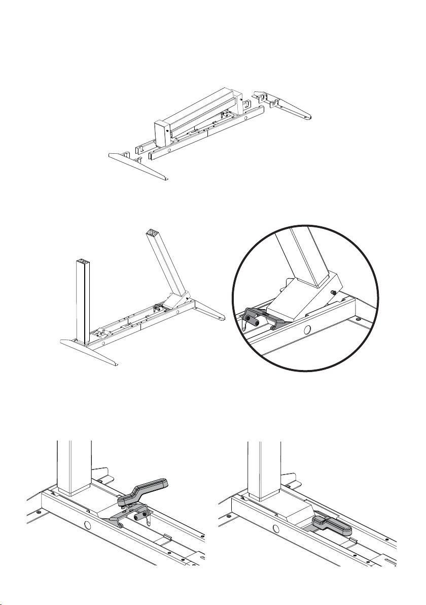
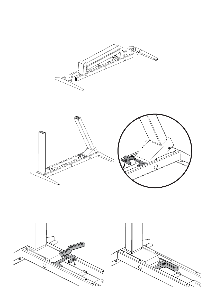
Assembly Instructions
Insert the (2) Wing Brackets into either side of the frame.
1
Ensure the buckle is raised. Raise the leg perpendicular to the frame, placing steadily into pocket.
2
Insert the Assembly Handle into the buckle and rotate until handle is in line with frame. Ensure
3
cables are clear of any moving parts. Push down hard on the handle until the buckle snaps into
place. Remove the handle and repeat on the opposite leg.
5
Page 6
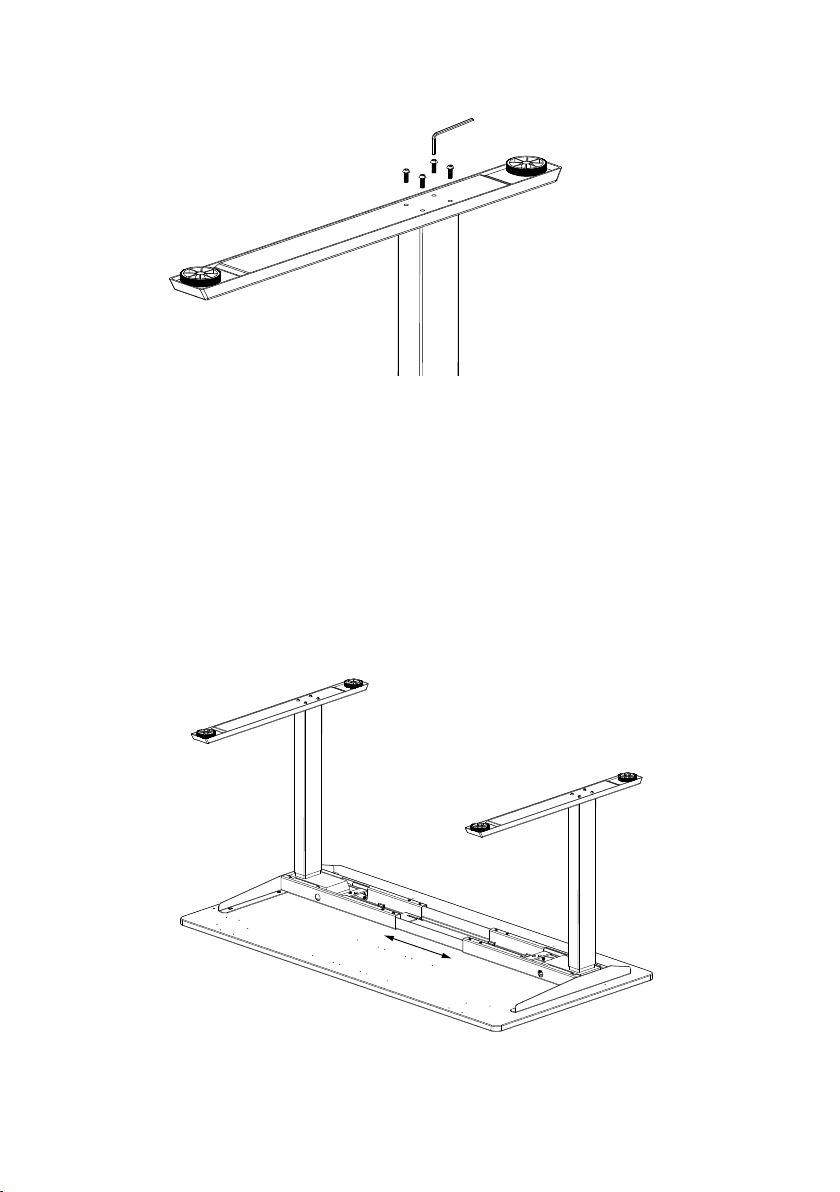
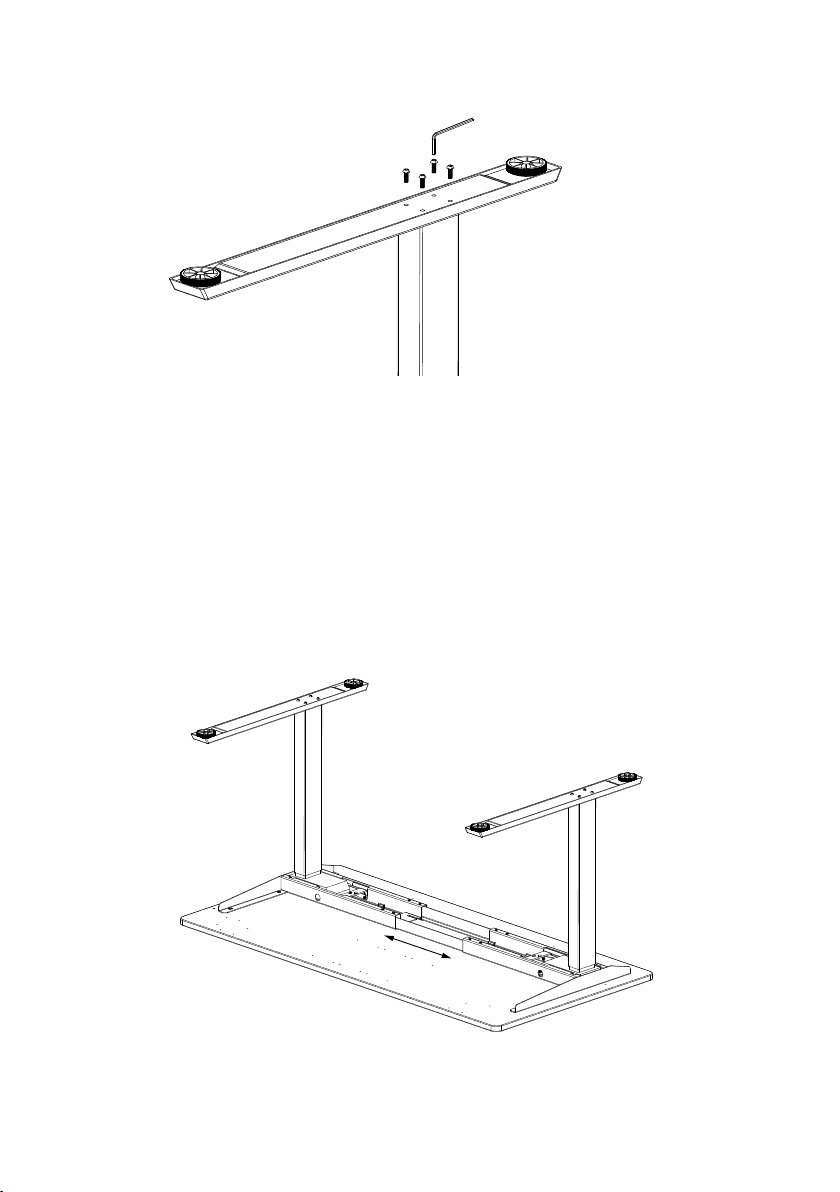
Using the (8) M6 X 14 Machine Screws secure the feet to the legs with the 4mm Allen Key.
4
Place your worksurface upside down on a protective surface. Lift and place the frame on top of
5
the worksurface. Adjust the width and position the frame on the worksurface per the following
sections:
A - Humanscale Worksurface
B - Using Your Own Work-surface.
6
Page 7
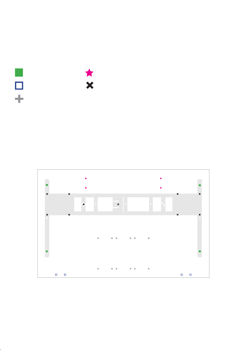
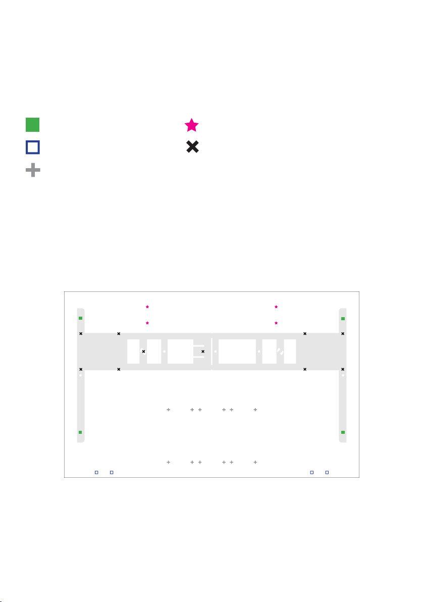
A - Humanscale Worksurface
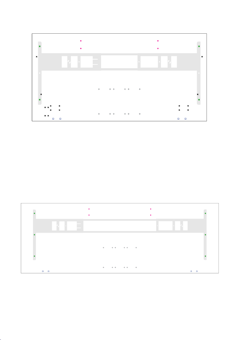
Align the legs to the following pilot holes highlighted below. Note: Only the four outer corner pilot
holes are included for alignment. Worksurfaces come with dierent pilot hole options depending on the
size ordered.
Legend
eFloat Go Base
eFloat Go Hand Switch
Keyboard Tray
48” Wide Worksurface
NeatTech (30” Deep Worksurfaces only)
Not applicable with this table
FRONT
7
Page 8
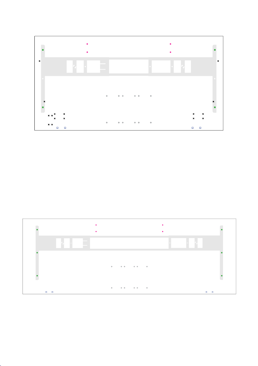
54-72” Wide Worksurfaces
78-84” Wide Worksurfaces
FRONT
FRONT
8
Page 9
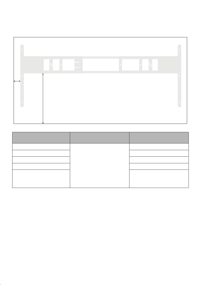
B - Your Own Worksurface
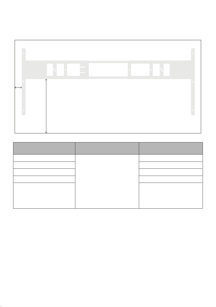
If using your own top, locate the Table Frame using the measurements listed below.
A
B
FRONT
Worksurface Depth A B
23”
24” 13.07" (332mm)
29” 16.76" (426mm)
30” 17.26" (438mm)
Worksurfaces between
23”- 30”
The 24” feet should be used for worksurfaces 23”-24” deep and the 30” feet should be used for the
worksurfaces 30” deep and less.
For worksurfaces wider than
76", set frame to max width of
2”
72".
12.57" (320mm)
Position frame by ensuring the
foot is centered with the depth
of the worksurface.
9
Page 10
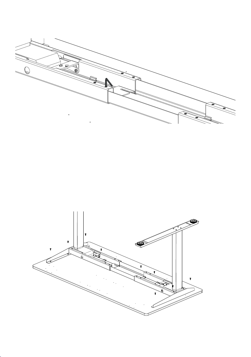
Once the frame is adjusted to the width of the worksurface, tighten the 8 set screws on the frame
6
with the 4mm Allen key.
Using the (9) ST5 X 20 Wood Screws secure the frame to the worksurface. If using a power drill
7
ensure it is set to low torque. If using a Humanscale Worksurface please note only the four outer
pilot holes are included to assist in aligning your worksurface to table base.
10
Page 11
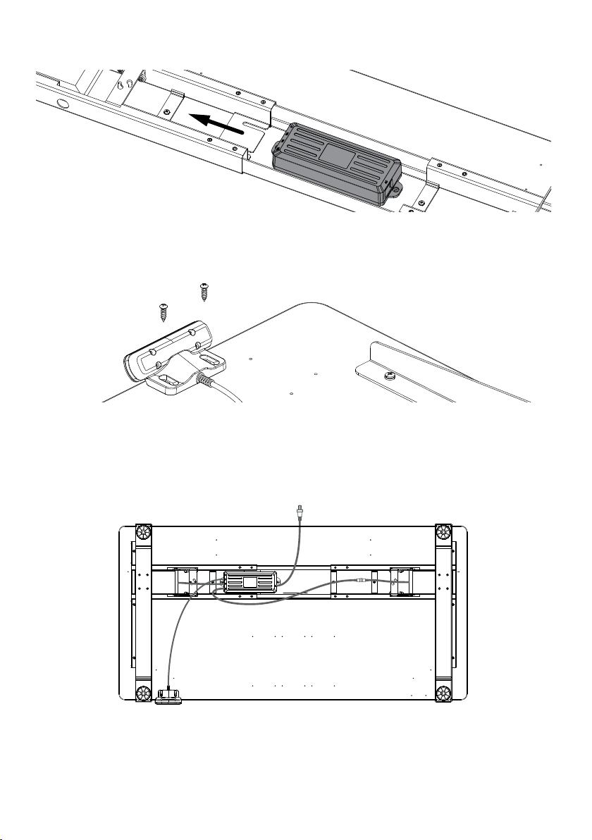
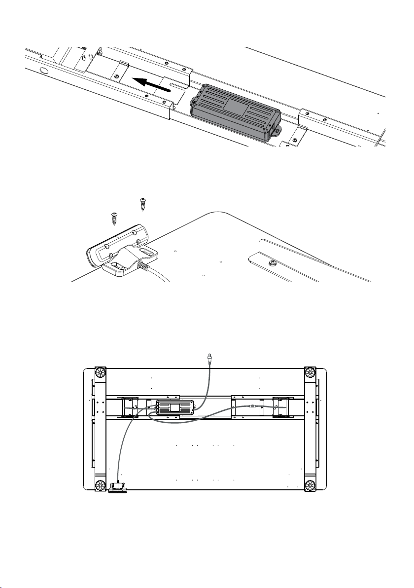
Slide the Control Box onto the frame, orientated with the (AC) Port for the power cord facing the
8
center of the table.
Secure the hand switch to the worksurface in your desired location using the (2) ST4 X 16, Wood
9
Screws along the front edge of worksurface. If using a Humanscale Universal Worksurface, pilot
holes are positioned on the left/right hand side of the worksurface in our recommended location(s).
Plug the Hand Switch into the Control Box. Connect the two legs to the Control Box, using the
10
Connecting Cable for the leg furthest away from the Control Box. Plug the Power Cord into the
Control Cox. Use the provided (10) Cable Ties to secure cables to underside of worksurface (not
pictured), with either double sided tape or the (10) ST5 X 20 Wood Screws.
Flip your table right side up and plug into outlet. Reset the desk per instructions in following
11
section.
YOU MUST RESET THE DESK BEFORE USE. FOLLOW INSTRUCTIONS ON INITIAL SETUP/RESET
UNDER HAND SWITCH
11
Page 12
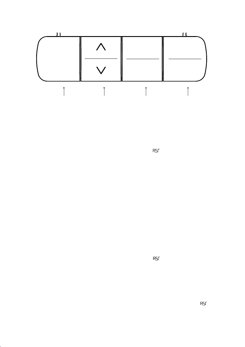
Hand Switch
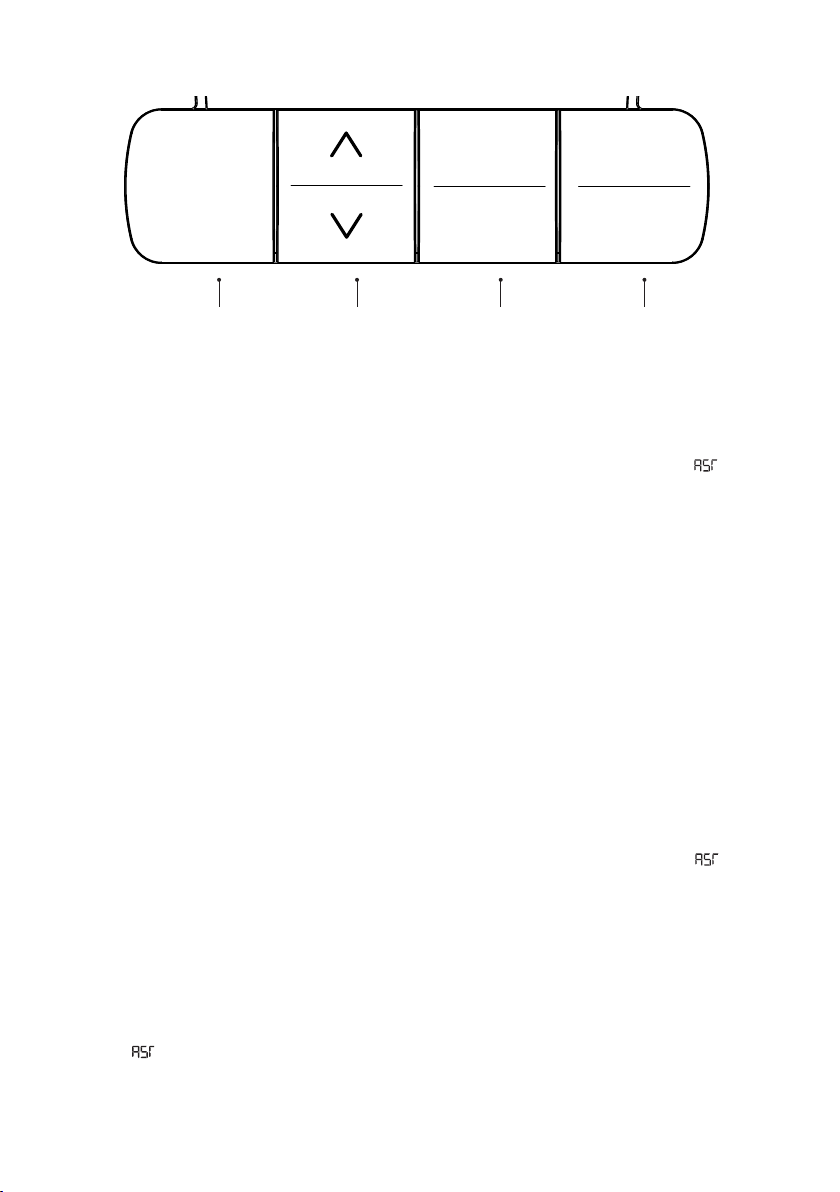
1
3
29.8
2
LED DISPLAY UP/DOWN
Initial Setup / Reset
IMPORTANT: You must RESET the desk before use.
1. Press the DOWN button, moving the desk to its lowest position, then release.
2. Hold the DOWN button until again, the LED display reads “ “.
3. Hold the DOWN button while the desk clicks lower, slightly rises and stops.
Your desk is now ready to use. The desk can be adjusted by pressing and holding either the UP/DOWN
button until the desired height is reached.
Setting Presets
Use the UP/DOWN buttons to find a desired height, then press “M” followed by a number 1 - 3, to set
the three presets.
CAUTION: Once a preset button is pushed, the desk will move to the programmed height.
PRESETS
M
MEMORY
Programming
Changing Units of Measurement
1. Press the DOWN button, moving the desk to its lowest position, then release.
2. Hold the DOWN button until again, the LED display reads “ “.
3. Hold the “2” button (about 5 seconds) to switch settings. Repeat until desired setting is
displayed.
10.3 = Metric (cm)
10.4 = Imperial (in)
4. Once the chosen setting is displayed, wait 5 seconds for the display to return to “ “.
5. Hold the DOWN button down while the desk lowers a little bit more, slightly rises and stops.
12
Page 13

One-Touch / Constant-Touch
Follow the steps below to change between One-Touch and Constant - Touch. One-Touch requires only
a single touch of the “1, 2 or 3” button to move the worksurface to a preset memory location. One-
Touch is the default setting. Constant-Touch requires a continuous touch of the “1, 2, or 3,” but ton to
move the worksurface to a preset memory location.
1. Press the DOWN button, moving the desk to its lowest position, then release.
2. Hold the DOWN button again, until the LED display reads “ “.
3. Hold the “1” button (about 5 seconds) to switch settings. Repeat until desired setting is
displayed.
10.1 = One-Touch
10.2 = Constant-Touch
4. Once the chosen setting is displayed, wait 5 seconds for the display to return to “ “.
5. Hold the DOWN button while the desk clicks lower, slightly rises and stops.
Setting LED Retracted Height
Press and hold the DOWN button until the worksurface reaches its lowest position. Measure the
distance from the floor to the top surface of the desktop. If the number on the LED display does NOT
match your measurement, follow these steps:
1. Hold the DOWN button again, until the LED display reads “ “.
2. Hold the “M” button (about 5 seconds) until the display starts ashing the height.
3. Use the UP/DOWN button to match your measurement.
4. Wait 5 seconds for the display to return to “ “.
5. Hold the DOWN button while the desk clicks lower, slightly rises and stops.
Setting Upper and Lower Limits
This desk is designed to go to its minimum and maximum heights, allowing for the longest possible
range. If you prefer to change the settings to a more shorter range, follow these steps:
To Set the Upper-Limit Position:
1. Use the UP /DOWN buttons to move the base to the desired maximum-height position.
2. Press the “M” button.
3. Press the UP button. The LED display will ash “S -”.
4. Hold the “M” button (about 2 seconds) until the LED display changes to “999”. The display will
automatically return to the selected height. The new upper limit is now set.
13
Page 14

To Set the LOWER-Limit Position:
1. Use the UP /DOWN buttons to move the base to the desired minimum-height position.
2. Press the “M” button.
3. Press the DOWN button and release. The LED display will ash “S -”.
4. Hold the “M” button (about 2 seconds) until the LED display changes to “000”. The display will
automatically return to the selected height. The new lower limit is now set.
To Remove the Upper/Lower Limit Positions:
1. Press the “M” button. The LED display will flash “S -”.
2. Press the “M” button again and hold for 2 seconds. The LED display will change to “555” and
then automatically return to the height display. The upper and lower limits are now removed.
Handset Lock
To lock the handset:
Press and hold the “M” button (about 8 seconds) until the LED display switches to “S -” and then to
“LOC.” Release the button.
To unlock the handset:
Press and hold the “M” button (about 8 seconds) until the LED switches from “LOC” to the height
display. Release the button.
14
Page 15
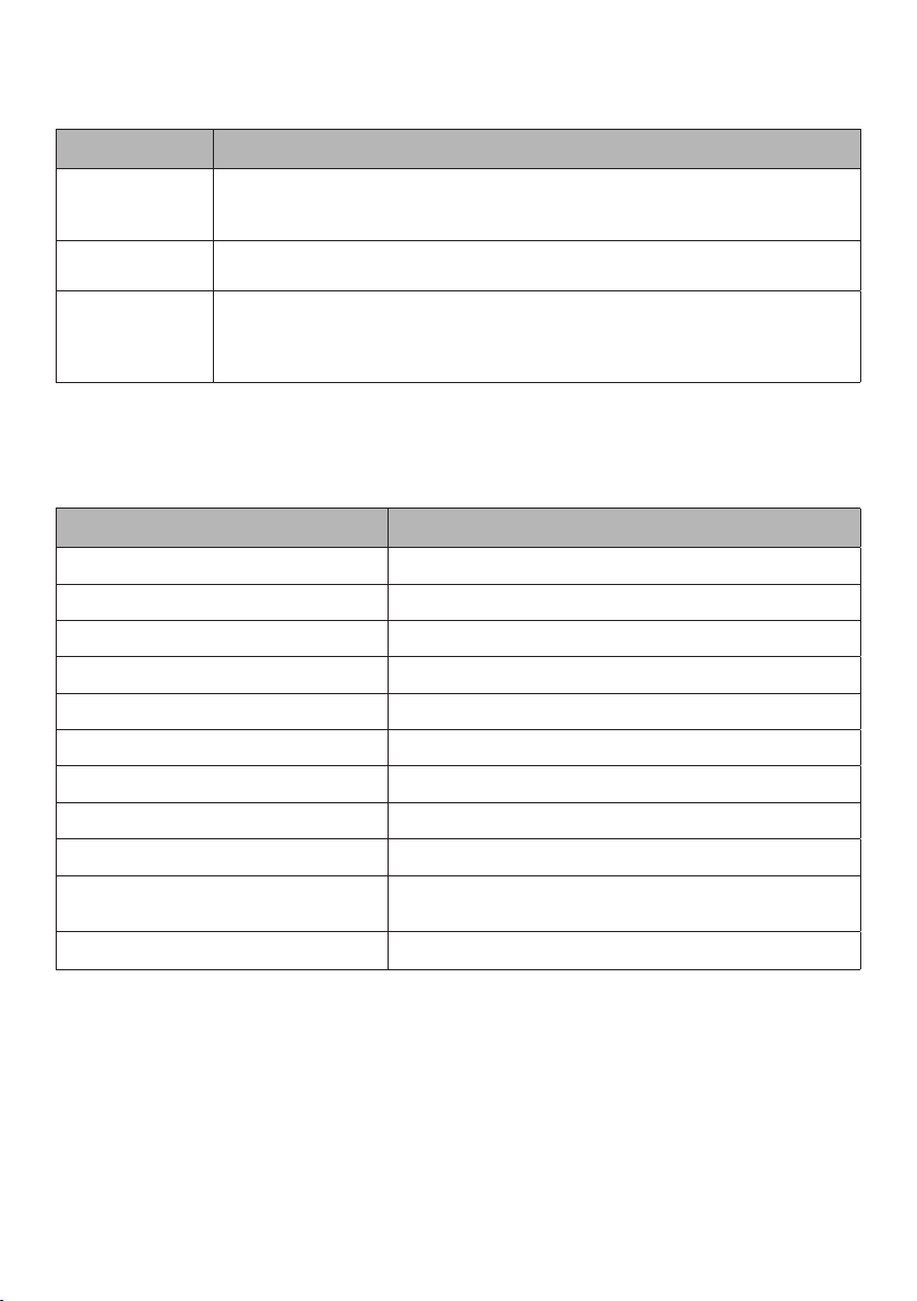
Troubleshooting
Error Solution
Table does not
move
Table moves at a
slow rate
Hand Switch
Error Codes:
E01 - E08
Ensure all cords are fully secured and the outlet your table is plugged into has
power.
Reset table.
Ensure all cables are fully secured. Follow the steps to reset your table. If you are
still encountering an error please call customer care.
Technical Data
Two-Column Kit
Power supply 120VAC 50/60Hz
Maximum input current 4.2A
Stand by power consumption, primarily <0.1W
Operating Temperature 5 - 40OC
Height Range (Standard Range) 26.8” - 46”
Height Range (Extended Stage) 21.5” - 47.6”
Base Width 42” - 72”
Travel Speed 1” per second (no load)
Noise Level <50dB
Maximum lift capacity
(Including worksurface)
Duty Cycle 10% Max. 2 min on, 18 mins o
250lbs
15
Page 16

Instructions importantes de sécurité
LORS DE L'UTILISATION D'UN MEUBLE AVEC COMPOSANT ÉLECTRIQUE, DES PRÉCAUTIONS
DE BASE DOIVENT TOUJOURS ÊTRE RESPECTÉES. LIRE TOUTES LES INSTRUCTIONS AVANT
D’UTILISER (CE MEUBLE). HUMMANSCALE NE PEUT PAS ÊTRE TENU RESPONSABLE DES
BLESSURES OU DOMMAGES CAUSÉS PAR LE NON RESPECT DE CES INSTRUCTIONS.
CONSERVER CES INSTRUCTIONS ET LES TRANSFÉRER AUX FUTURS UTILISATEURS.
DANGER: Pour réduire les risques de décharge électrique, débrancher ce meuble de la prise
électrique avant le nettoyage.
AVERTISSEMENT: Pour réduire les risques de brûlures, d’incendie, de décharges électriques ou
de blessures corporelles:
• Une surveillance étroite est nécessaire lorsque ce meuble est utilisé par ou à proximité
d’enfants, d’invalides ou de personnes handicapées.
• Utiliser ce meuble uniquement pour l’usage auquel il est destiné, tel que décrit dans ces
instructions. Ne pas utiliser d’accessoires non recommandés par le fabricant.
• Si la surface de travail utilisée avec ce meuble n’est pas de la taille ou de la forme appropriée ou
n’est pas montée correctement et fixée au meuble, le produit assemblé pourrait être instable,
s’eondrer ou provoquer une défaillance des composants électriques.
• Ne jamais utiliser ce meuble s’il a un cordon ou une fiche endommagé, s’il ne fonctionne pas
correctement, s’il est tombé ou endommagé, ou s’il est tombé dans l’eau. Retourner le meuble
à un centre de réparation à des fins d’inspection et de réparation.
• Garder le cordon éloigné des surfaces chauées.
• Ne jamais utiliser le produit lorsque les ouvertures d’air sont obstruées. Garder les ouvertures
d’air exemptes de peluches, de cheveux et autres.
• Ne jamais laisser tomber ou insérer un objet quelconque dans une ouverture.
• Ne pas utiliser à l’extérieur.
• Ne pas utiliser là où des produits en aérosol (vaporisés) sont utilisés ou là où de l’oxygène est
administré.
• Pour débrancher, mettre toutes les commandes en position d’arrêt, puis retirer la fiche de la prise.
AVERTISSEMENT: Risque de décharge électrique - Brancher ce meuble uniquement dans une
prise correctement mise à la terre. Consulter les instructions de mise à la terre
NE PAS SURCHARGER LE BUREAU: Pour éviter que la table ne bascule ou ne s’eondre, s’assurer
que le bureau n’est pas surchargé par le poids de la surface de travail et des articles posés sur la table.
Répartir la charge uniformément; la présence des charges excessives aux extrémités peuvent réduire la
stabilité et mener au basculement.
• E Float Go - Ensemble à deux colonnes - Les surfaces de travail doivent être rectangulaires
et avoir une épaisseur minimale de 0,75po (20mm), une profondeur de 23 à 35pouces et
une largeur de 46 à 82pouces. Pour des raisons de stabilité, la taille maximale de la surface de
travail est de 35po x 82po.
16
Page 17

• Ne pas dépasser la charge maximale, y compris le poids de la surface de travail, de 250Ib (113kg)
• Les pieds de 24po doivent être utilisés pour les surfaces de travail de 23 à 24po de profondeur
tandis que les pieds de 30po doivent être utilisés pour les surfaces de travail de 30po de
profondeur et moins.
• Pour le chargement, toujours placer les éléments plus lourds au centre et répartir ensuite la charge.
• Ne pas s’asseoir ou se tenir debout sur la table.
FAIRE ATTENTION LORS DE L’UTILISATION DU BUREAU:
• Examiner la table pour détecter des signes visibles de dommages avant son utilisation. Ne pas
utiliser un produit endommagé.
• S’assurer qu’aucun obstacle ne se trouve sur le chemin du bureau et que celui-ci ne touche pas
les murs ou les objets à proximité.
• Les éléments d’une hauteur supérieure à 20po ne doivent pas être placés ou rangés sous le
bureau.
• Garder le cadre de la table sec. Garder tous les composants électriques loin de l’eau et d'un
taux d’humidité élevé. Ne pas vaporiser de solutions de nettoyage directement sur le cadre de
la table.
• La température de fonctionnement de la table se situe entre 5 et 40OC
• S’assurer que tous les cordons ont la longueur appropriée pour s’adapter aux variations de
hauteur.
• Bien que ce produit soit doté d’une fonctionnalité anti-collision, afin d’éviter tout pincement,
s’assurer que les mains ou les autres parties du corps sont protégées durant l'utilisation.
• Débrancher le cordon d’alimentation par temps orageux ou si ’il n’est pas prévu d’utiliser la table
pendant une longue période.
• Ne jamais utiliser la table si un cordon ou une prise est endommagé.
• Garder le cordon éloigné des surfaces chauées.
• Au fil du temps, de la graisse peut s’accumuler sur les colonnes intérieures des pattes de la
table. Si cela se produit, essuyer les colonne à l'aide d'un chion doux.
NE PAS OUVRIR LES COMPOSANTS ÉLECTRIQUES: Ne pas essayer de réparer les composants de la
table. Le boîtier de commande du moteur, le commutateur à main et les pattes de la table ne comportent
aucun composant pouvant être réparé par l’utilisateur. Si votre table nécessite une réparation ou si vous
rencontrez des dicultés avec votre table, merci de communiquer avec le service clientèle.
INSTRUCTIONS DE MISE À LA TERRE: Ce produit est destiné à être utilisé sur un circuit nominal de
120volts et possède une fiche de mise à la terre qui ressemble à la fiche illustrée ci-dessous. S'assurer
que le produit est raccordé à une prise ayant la même configuration que la fiche. Aucun adaptateur ne
doit être utilisé avec ce produit.
PRISE MISE
À LA TERRE
BROCHE
MISE À LA
TERRE
Ne pas modifier la fiche fournie avec le produit - elle ne correspondra pas aux prises, faire installer une
prise appropriée par un électricien qualifié.
17
Page 18
Avant de commencer
• En cas d’utilisation d’une perceuse électrique, procéder à un réglage de couple faible.
• Monter le produit sur une surface de protection.
• 2personnes ou plus peuvent être nécessaires pour manœuvrer la table.
• Après l’assemblage, la table devra faire l’objet d’un réglage/réinitialisation initial avant de
pouvoir être utilisée.
Outils nécessaires
①
②
③
Tournevis à tête cruciforme
Perceuse électrique avec embout
cruciforme
Ruban à mesurer
Pièces incluses
①
Assemblage des pattes
④ ⑦
Surface de travail Humanscale
(CONFIGURATION SPÉCIFIQUE,
CONDITIONNEMENT SÉPARÉ)
⑧
Alimentation électrique
⑤ ⑥
⑨
②
Supports des ailes gauche et droite
Poignée d’assemblage
Câble de connexion
③
Commutateur à main
⑩ ⑪
(10) Serre-câbles
(2) Pieds
Boîtier de commande
Clé hexagonale de 4mm
Matériel inclus
①
(8) 14vis à métauxM6
18
②
(19) 20vis à boisST5
③
(2) 16vis à boisST4
Page 19
Instructions de montage
Insérer les (2) supports d'ailes de chaque côté du cadre.
1
S’assurer que la boucle est relevée. Relever la patte perpendiculairement au cadre, en la plaçant
2
fermement dans la poche.
Insérer la poignée d’assemblage dans la boucle et la faire tourner jusqu’à ce qu’elle soit alignée
3
avec le cadre. S’assurer que les câbles sont à l’écart de toute pièce mobile. Appuyer fortement
sur la poignée jusqu’à ce que la boucle s'enclenche. Retirer la poignée et faire de même sur la
patte opposée.
19
Page 20
À l’aide des (8) 14vis à métauxM6, fixez les pieds aux pattes à l’aide de la clé hexagonale de
4
4mm.
Poser la surface de travail à l’envers sur une surface de protection. Soulever et placer le cadre
5
sur la surface de travail. Ajuster la largeur et la position du cadre sur la surface de travail,
conformément aux sections suivantes:
A - Surface de travail Humanscale
B - Utiliser votre propre surface de travail.
20
Page 21
A - Surface de travail Humanscale
Aligner les pattes sur les avant-trous illustrés ci-dessous. Remarque: seuls les quatre avant-trous
des coins extérieurs sont concernés par l’alignement. Les surfaces de travail sont proposées avec
diérentes options d’avant-trous en fonction de la taille commandée.
Légende
Base eFloat Go
Commutateur à main eFloat Go
Plateau pour clavier
Surface de travail de 48po de largeur
NeatTech (uniquement pour les surfaces
de travail de 30po de profondeur)
Non applicable à cette table
DE FACE
21
Page 22
Surfaces de travail de 54 à 72po de largeur
Surfaces de travail de 78 à 84po de largeur
DE FACE
22
DE FACE
Page 23
B - Votre propre surface de travail.
En cas d’utilisation de votre propre plateau, positionner le cadre de la table en utilisant les mesures
indiquées ci-dessous.
A
B
DE FACE
Profondeur de la surface de
Surfaces de travail entre
58 et 76cm (23 et 30po)
travail
58cm (23po)
61cm (24po) 13,07po (332mm)
73cm (29po) 16,76po (426mm)
76cm (30po) 17,26po (438mm)
Pour les surfaces de travail
d’une largeur supérieure à
76po, régler le cadre à une
largeur maximale de 72po.
A B
12,57po (320mm)
5cm (2po)
Positionner le cadre en
s’assurant que le pied est centré
à l’aune de la profondeur de la
surface de travail.
Les pieds de 24po doivent être utilisés pour les surfaces de travail de 23 à 24po de profondeur tandis
que les pieds de 30po doivent être utilisés pour les surfaces de travail de 30po de profondeur et
moins.
23
Page 24

Une fois que le cadre est ajusté selon la largeur de la surface de travail, serrer les 8ensembles de
6
vis sur le cadre à l’aide de la clé hexagonale de 4mm.
Utiliser les (9) 20vis à boisST5 pour fixer le cadre à la surface de travail. En cas d’utilisation d’une
7
perceuse électrique, s’assurer de la régler à un couple faible. En cas d’utilisation d’une surface de
travail Humanscale, veuillez retenir que seuls les quatre avant-trous extérieurs sont inclus pour
aider à l’alignement de votre surface de travail sur la base de la table.
24
Page 25
Faire glisser le boîtier de commande sur le cadre, en orientant le port (CA) du cordon
8
d’alimentation vers le centre de la table.
Fixer le commutateur à main sur la surface de travail à l’endroit souhaité à l’aide des (2) 16vis
9
à boisST4, le long du bord avant de la surface de travail. En cas d’utilisation d’une surface de
travail universelle Humanscale, les avant-trous sont positionnés sur les côtés gauche et droit de la
surface de travail, aux endroits recommandés.
Brancher le commutateur à main dans le boîtier de commande. Relier les deux pattes au boîtier de
10
commande, en utilisant le câble de connexion de la patte la plus éloignée du boîtier de commande.
Brancher le cordon d’alimentation dans le boîtier de commande. Utiliser les (10) serre-câbles
fournis pour fixer les câbles au dessous de la surface de travail (non illustré), avec du ruban adhésif
double face ou les (10) 20vis à boisST5.
Retourner votre table à l’endroit et la brancher. Réinitialiser le bureau selon les instructions de la
11
section suivante.
LE BUREAU DOIT ÊTRE RÉINITIALISÉ AVANT D'ÊTRE UTILISÉ. SUIVRE LES INSTRUCTIONS SUR
LA CONFIGURATION INITIALE/RÉINITIALISATION SOUS LE COMMUTATEUR À MAIN
25
Page 26
Commutateur à main
1
3
29.8
2
ÉCRAN À DEL HAUT/BAS PRÉRÉGLAGES MÉMOIRE
Configuration/Réinitialisation initiale
IMPORTANT: le bureau doit être RÉINITIALISÉ avant d'être utilisé.
1. Appuyer sur le bouton BAS, en déplaçant le bureau à sa position la plus basse, puis relâcher.
2. Maintenir le bouton BAS enfoncé jusqu’à ce que l’écran à DEL afche à nouveau « ».
3. Maintenir le bouton BAS enfoncé pendant que le bureau s’abaisse, se relève légèrement et s’arrête.
Votre bureau est désormais prêt à l’emploi. Le bureau peut être réglé en appuyant sur le bouton HAUT/
BAS et en le maintenant enfoncé jusqu’à ce que la hauteur souhaitée soit atteinte.
Réglage des préréglages
Utiliser les boutons HAUT/BAS pour trouver la hauteur désirée, puis appuyer sur «M» suivi d’un chire
de 1 à 3, pour régler les trois préréglages.
AVERTISSEMENT: Une fois un bouton de préréglage appuyé, le bureau se déplacera à la hauteur
programmée.
M
Programmation
Changer les unités de mesure
1. Appuyer sur le bouton BAS, en déplaçant le bureau vers sa position la plus basse, puis relâcher.
2. Maintenir le bouton BAS enfoncé jusqu’à ce que l’écran à DEL afche à nouveau « ».
3. Maintenir le bouton «2» enfoncé (environ 5secondes) pour changer les paramètres. Répéter
l’opération jusqu’à ce que le paramètre souhaité s’afche.
10,3 = Métrique (cm)
10,4 = Impérial (po)
4. Une fois que le paramètre sélectionné s’afche, patienter 5secondes pour que l’écran retourne
à « ».
5. Maintenir le bouton BAS enfoncé pendant que le bureau s’abaisse un peu plus encore, monte
légèrement et s’arrête.
26
Page 27

One-Touch / Constant-Touch
Suivre les étapes ci-dessous pour passer de la touche unique à la touche constante. La fonction OneTouch ne nécessite qu’une seule pression sur le bouton «1, 2 ou 3» pour déplacer la surface de travail
vers un emplacement de mémoire prédéfini. One-Touch est le paramètre par défaut. La fonction
Constant-Touch nécessite une pression continue sur le bouton «1, 2 ou 3» pour déplacer la surface de
travail vers un emplacement de mémoire prédéfini.
1. Appuyer sur le bouton BAS, en déplaçant le bureau vers sa position la plus basse, puis relâcher.
2. Maintenir le bouton BAS enfoncé jusqu’à ce que l’écran à DEL afche à nouveau « ».
3. Maintenir le bouton «1» enfoncé (environ 5secondes) pour changer les paramètres. Répéter
l’opération jusqu’à ce que le paramètre souhaité s’afche.
10.1 = One-Touch
10.2 = Constant-Touch
4. Une fois que le paramètre sélectionné s’afche, patienter 5secondes pour que l’écran retourne
à « ».
5. Maintenir le bouton BAS enfoncé pendant que le bureau s’abaisse, se relève légèrement et
s’arrête.
Réglage de la hauteur de DEL rétractée
Appuyer et maintenir le bouton BAS enfoncé jusqu’à ce que la surface de travail atteigne sa position la
plus basse. Mesurer la distance entre le sol et la surface supérieure du bureau. Si le chire aché sur
l’écran à DEL ne correspond PAS à votre mesure, suivre les étapes suivantes:
1. Maintenir le bouton BAS enfoncé jusqu’à ce que l’écran à DEL ache à nouveau « ».
2. Maintenir le bouton «M» enfoncé (environ 5secondes) jusqu’à ce que l’écran commence à
clignoter pour indiquer la hauteur.
3. Utiliser la touche HAUT/BAS pour correspondre à vos mesures.
4. Patienter pendant 5secondes pour que l’écran retourne à « ».
5. Maintenir le bouton BAS enfoncé pendant que le bureau s’abaisse, se relève légèrement et
s’arrête.
Définir les limites supérieures et inférieures
Ce bureau est conçu pour atteindre ses hauteurs minimales et maximales, permettant ainsi la plus
grande portée possible. Si vous préférez modifier les réglages pour une portée plus courte, suivez les
étapes suivantes:
27
Page 28

Pour définir la position de la limite supérieure:
1. Utiliser les boutons HAUT/BAS pour déplacer la base jusqu’à la position de hauteur maximale
souhaitée.
2. Appuyer sur le bouton «M».
3. Appuyer sur le bouton HAUT. L’écran à DEL clignotera pour afcher «S - ».
4. Maintenir le bouton «M» enfoncé (environ 2secondes) jusqu’à ce que l’écran à DEL passe
à «999». L’écran retournera automatiquement à la hauteur sélectionnée. La nouvelle limite
supérieure est désormais réglée.
Pour définir la position de la limite INFÉRIEURE:
1. Utiliser les boutons HAUT/BAS pour déplacer la base jusqu’à la position de hauteur minimale
souhaitée.
2. Appuyer sur le bouton «M».
3. Appuyer sur le bouton BAS et relâcher. L’écran à DEL clignotera pour afcher «S - ».
4. Maintenir le bouton «M» enfoncé (environ 2secondes) jusqu’à ce que l’écran à DEL passe
à «000». L’écran retournera automatiquement à la hauteur sélectionnée. La nouvelle limite
inférieure est désormais réglée.
Pour retirer les positions des limites supérieures/inférieures:
1. Appuyer sur le bouton «M». L’écran à DEL clignotera pour acher «S - ».
2. Appuyer à nouveau sur le bouton «M» et maintenir enfoncé pendant 2secondes. L’écran
à DEL passera à «555» et reviendra automatiquement à la hauteur afchée. Les limites
supérieures et inférieures sont à présent supprimées.
Verrouillage du combiné
Pour verrouiller le combiné:
Appuyer et maintenir le bouton «M» enfoncé (environ 8secondes) jusqu’à ce l’écran à DEL passe à
«S - », puis à «LOC». Relâcher le bouton.
Pour déverrouiller le combiné:
Appuyer et maintenir le bouton «M» enfoncé (environ 8secondes) jusqu’à ce l’écran à DEL passe de
«LOC» à la hauteur achée. Relâcher le bouton.
28
Page 29
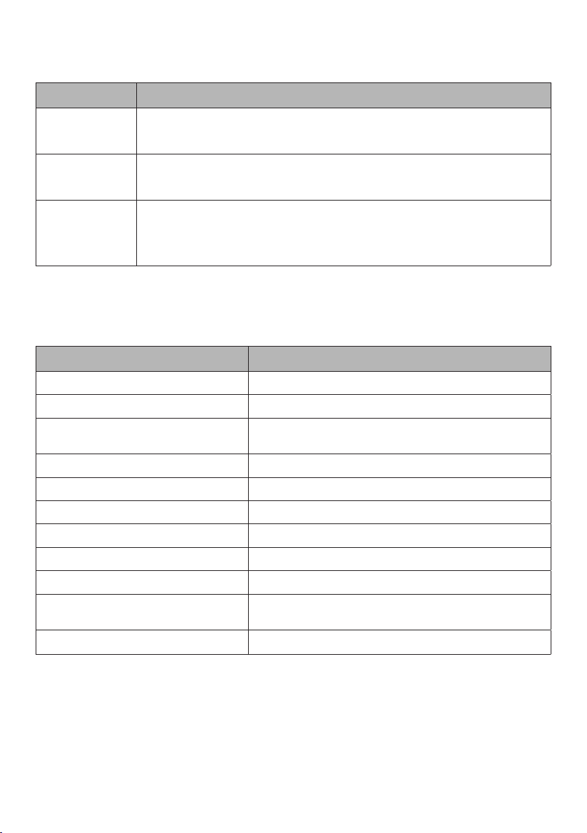
Dépannage
Erreur Solution
La table ne se
déplace pas
La table
se déplace
lentement
Codes d’erreur
du commutateur
à main:
E01 - E08
S’assurer que tous les cordons sont complètement fixés et que la prise de votre
table est branchée sous secteur.
Réinitialiser la table.
S’assurer que tous les câbles sont correctement raccordés. Suivre les étapes
de réinitialisation de votre table. En cas de nouvelle erreur, merci d’appeler le
service clientèle.
Données techniques
Ensemble à deux colonnes
Alimentation en énergie 120VCA 50/60Hz
Courant d’entrée maximal 4,2A
Consommation d’énergie en mode
veille, principalement
Température de fonctionnement 5-40 °C
Plage de hauteur (plage standard) 68 à 117cm (26,8 à 46po)
Plage de hauteur (Stade prolongé) 55 à 121cm (21,5 à 47,6po)
Largeur de la base 107 à 182cm (42po à 72po)
Vitesse de course 1po par seconde (aucune charge)
Niveau de bruit <50dB
Capacité de levage maximale
(Y compris la surface de travail)
Cycle de service 10% Max. 2minutes de marche, 18minutes d’arrêt
<0,1W
113kg (250lb)
29
Page 30

30
Page 31

31
Page 32

FCC Notice
FG1224D_, FG1230D_, FGDG2224D_, FG2230D_ (where “_” is any alphanumeric character denoting color)
This device complies with part 15 of the FCC Rules. Operation is subject to the following two conditions: (1) This device may not cause harmful
interference, and (2) this device must accept any interference received, including interference that may cause undesired operation.
NOTE: This equipment has been tested and found to comply with the limits for a Class B digital device, pursuant to part 15 of the FCC Rules.
These limits are designed to provide reasonable protection against harmful interference in a residential installation. This equipment generates,
uses and can radiate radio frequency energy and, if not installed and used in accordance with the instructions, may cause harmful interference
to radio communications. However, there is no guarantee that interference will not occur in a particular installation. If this equipment does cause
harmful interference to radio or television reception, which can be determined by turning the equipment o and on, the user is encouraged to try
to correct the interference by one or more of the following measures:
• Reorient or relocate the receiving antenna.
• Increase the separation between the equipment and receiver.
• Connect the equipment into an outlet on a circuit dierent from that to which the receiver is connected.
• Consult the dealer or an experienced radio/TV technician for help.
Changes or modifications made to this device that are not expressly approved by Humanscale may void the user’s authority to operate the
equipment.
1114 6th Ave, 15th Floor
New York, NY 10036
humanscale.com
For our terms and conditions please go to
https://www.humanscale.com/about/legal-information/terms-conditions.cfm
© 2021 Humanscale Corporation. The text and artwork are copyrighted materials. All rights reserved. The Humanscale mark and logo are
trademarks of Humanscale Corporation and are registered in the United States and certain other countries.
12/14/2021
GT-NPD-AI-8897-001-R03
 Loading...