

Page 1
MANUAL
BEDIENUNGSANLEITUNG
100 WATTS TUBE GUITAR AMPLIFIER
English - Page 2
Deutsch - Seite 13
STANDBY
PRESENCE
0510
MASTER
0510
MIDI LEARN
FX-MIX
DRY WET
FX LOOP
AMP 3 MASTER
0510
TREBLE
-50+5
MID
-50+5
AMP 3
BASS
-50+5
GAIN B
0510
CHANNEL B
0510
CHANNEL A
AMP 2 MASTER
5
0
10
TREBLE
-50+5
MID
0
+5 -50+5
-5
AMP 2
GAIN BBASS
0510
CHANNEL B
GAIN A
0510
CHANNEL A
AMP 1 MASTER
0510
TREBLE
-50+5
TIGHT
GAIN BBASSMID GAIN A
05100510-50+5-50+5
CHANNEL ACHANNEL B
AMP 1
GAIN A
INPUT
Page 2

IMPORTANT SAFETY INSTRUCTIONS!
BEFORE CONNECTING, READ INSTRUCTIONS
Read all of these instructions !
Save these instructions for later use !
Follow all warnings and instructions marked on the product !
Do not use this product near water !
Do not place this product on an unstable cart, stand or table. The product may fall,
causing serious damage to the product!
Slots and openings in the cabinet and the back or bottom are provided for ventilation;
to ensure reliable operation of the product and to protect it from overheating, these
openings must not be blocked or covered. This product should not be placed in a
built-in installation unless proper ventilation is provided.
This product should be operated from the type of power source indicated on the
marking label. If you are not sure of the type of power available, consult your
dealer or local power company.
This product is equipped with a 3-wire grounding type plug, a plug having a third pin.
This plug will only fit into a grounding-type power outlet. This is a safety feature.
If you are unable to insert the plug into the outlet, contact your electrician to replace
your obsolete outlet. Do not defeat the purpose of the grounding type plug.
Do not allow anything to rest on the power cord. Do not locate this product where
persons will walk on the cord.
If an extension cord is used with this product make sure that it is a 3-wire
groundingtype and that the total of the amp ere ratings on the products plugged into
the extension cord do not exceed the extension cord ampere rating. Also make sure
that the total of all products plugged into the wall outlet does not exceed 15 amperes.
Never push objects of any kind into this product through cabinet slots as may touch
dangerous voltage points or short out parts that could result in risk of fireor electric
shock. Never spill liquid of any kind on the product.
Do not attempt to service this product yourself, as opening or removing covers may
expose you to dangerous voltage points or other risks. Refer all servicingto service
personnel.
Unplug this product from the wall outlet and refer servicing to qualified service
personnel under the following conditions:
Unplug this product from the wall outlet and refer servicing to qualified service
personnel under the following conditions:
When the power cord or plug is damaged or frayed .
If liquid has been spilled into the product.
If the product has been exposed to rain or water .
If the product does not operate normally when the operating instructions are followed.
Adjust only these controls that are covered by the operating instructions since
improper adjustment of other controls may result in damage and will often require
extensive work by a qualified technician to restore the product to normal operation.
If the product has been dropped or the cabinet has been damaged.
If the product exhibits a distinct change in performance, indicating a need of service!
Selection of power supply cord. Use only a listed detachable power supply cord type
SVT or SJT minimum 18 AWG, 3 conductor, one end configured for NEMA 5-15 other
end for IEC 320/CEE 22!
Fuses: For continued protection against risk of fire, replace fuses only with same type
and ratings
TO PREVENT THE RISK OF FIRE AND SHOCK HAZARD, DO NOT
EXPOSE THIS APPLIANCE TO MOISTURE OR RAIN. DO NOT OPEN
CASE; NO USER SERVICE-ABLE PARTS INSIDE.
REFER SERVICING TO QUALIFIED SERVICE PERSONNEL.
2
TRIAMP - Manual
WICHTIGE SICHERHEITSHINWEISE!
BITTE VOR GEBRAUCH LESEN!
Das Gerät wurde von HUGHES & KETTNER gemäß VDE 0860 gebaut und
hat das Werk in sicherheitstechnisch einwandfreiem Zustand verlassen. Um
diesen Zustand zu erhalten und einen gefahrlosen Betrieb sicherzustellen,
muß der Anwender die Hinweise und die Warnvermerke beachten,die in
der Bedienungsanleitung enthalten sind. Das Gerät entspricht der
Schutzklasse I ( schutzgeerdet ).
DIE SICHERHEIT, ZUVERLÄSSIGKEIT UND LEISTUNG DES GERÄTES
WIRD VON HUGHES & KETTNER NUR DANN GEWÄHRLEISTET, WENN:
- Montage, Erweiterung, Neueinstellung, Änderungen oder Reparaturen von HUGHES
& KETTNER ermächtigten Personen ausgeführt werden
- die elektrische Installation des betreffenden Raumes den Anforderungen von IEC
(ANSI)- Festlegungen entspricht
- das Gerät in Übereinstimmung mit der Gebrauchsanweisung verwendet wird.
Warnung:
Jegliche Unterbrechung des Schutzleiters innerhalb oder außerhalb des Gerätes oder
Lösen des Schutzleiteranschlusses kann dazu führen, daß das Gerätes gefahrbringend
wird. Absichtliches Unterbrechen des Schutzleiters ist unzulässig.
Wenn Abdeckungen geöffnet oder Gehäuseteile entfernt werden,außer wenn dies von
Hand möglich ist, können Teile freigelegt werden, die Spannung führen.
Alle Stecker an den Verbindungskabeln müssen mit dem Gehäuse verschraubt oder
verriegelt sein.
Wenn ein Öffnen des Gerätes erforderlich ist, muß das Gerät von allen
Spannungsquellen getrennt sein. Berücksichtigen Sie dies - vor dem Abgleich, - vor
einer Wartung, - vor einer Instandsetzung, vor einem Austausch von Teilen.
Ein Abgleich, eine Wartung oder eine Reparatur am geöffneten Gerät unter Spannung
darf nur durch eine vom Hersteller autorisierte Fachkraft geschehen, die mit den damit
verbundenen Gefahren vertraut ist.
Es dürfen nur Sicherungen vom angegebenen Typ und der angegebenen
Nennstromstärke als Ersatz verwendet werden.
Eine Verwendung von geflickten Sicherungen oder Kurzschließen des Halters ist
unzulässig.
Der Netzstecker darf nur in eine Steckdose mit Schutzkontakt eingeführt werden.
NETZANSCHLUSS:
Der HUGHES & KETTNER TRIAMP ist für Dauerbetrieb ausgelegt.
Die eingestellte Betriebsspannung muß mit der örtlichen Netzspannung
übereinstimmen.
Achtung: Der Netzschalter des Gerätes muß in 0 - Position stehen, wenn das
Netzkabel angeschlossen wird.
Der Anschluß an das Stromnetz erfolgt mit dem mitgelieferten Netzkabel.
Verwenden Sie nur Neztanschlußkabel wie im Lieferumfang vorhanden oder
Geräteanschlußleitungen mit Schukostecker DIN 49441, IEC 83 und KaltgeräteSteckdose DIN 49547, IEC 320 Kabeltyp HO5VV-F3G o,75 (PVC Schlauchleitung mit
min 3 x 0,75qmm, Länge max.3 m).
Vermeiden Sie einen Anschluß in Verteilerdosen zusammen mit vielen anderen
Stromverbrauchern.
Die Steckdose für die Stromversorgung muß nahe am Gerät angebracht und leicht
zugänglich sein.
Absichtliche Unterbrechung des Schutzleiters ist unzulässig.
AUFSTELLUNGSORT:
Das Gerät sollte nur auf einer sauberen, waagerechten Arbeitsfläche stehen.
• Das Gerät darf während des Betriebs keinen Erschütterungen ausgesetzt sein.
• Feuchtigkeit und Staub sind nach Möglichkeit fernzuhalten.
• Sorgen Sie für ausreichende Belüftung der Geräte.
• Vermeiden Sie direkte Sonneneinstrahlung sowie die unmittelbare Nähe von
Heizkörpern und Heizstrahlern.
Page 3

3
TRIAMP - Manual
CONTENTS Page
1.0 TRIAMP: THE THREE AMPS 4
2.0 CONNECTIONS AND CONTROL FEATURES 5
2.1 AC POWER
AND THE GLOBAL CURRENT ADAPTER
2.2 OVERVIEW OF CONTROL FEATURES 6
3.0 STANDARD SETUP / CABLE CONNECTIONS 8
4.0 TRIAMP OPERATION
4.1 CHANNEL SELECTION
4.2 TRIAMP AND SIGNAL PROCESSORS
4.3 RED BOX DI OUT
- ALL-TUBE TONE TO THE MIXER 9
4.4 TRIAMP AND MIDI
5.0 REPLACING TUBES, SERVICE
AND PREVENTIVE MAINTENANCE 10
6.0 TROUBLESHOOTING 11
7.0 TECHNICAL SPECIFICATIONS 23
Congratulations and thank you for
purchasing the TRIAMP all-tube guitar
amplifier. TriAmp is the world's first amp to
house three completely different all-tube
amps in one head.
Over the past forty years, thousands of amps have
appeared on the market, of which only a few have
become coveted classics. Tone quality and
response to the player's touch are the attributes
that have made these amps so uncommonly
popular, so much so that they fetch uncommonly
high prices today.
TriAmp deeply honors the past, but breaks through
its limitations. Like its classical predecessors,
TriAmp utilizes classic components exclusively,
such as vacuum tubes and resistors. But TriAmp
introduces new technologies that put these
timeless components to work in unique new ways,
offering you an absolute diversity of tone not
available from any other all-tube amp.
For the first time in amp history, TriAmp offers the
tube purist three heads in one: the past, present,
and future of all-tube tone.
Page 4

4
TRIAMP - Manual
1.0 TRIAMP
- Three amps in a single chassis.
Three completely different all-tube amplifiers in one housing
- three totally unique worlds of authentic tone in one head this has been a seemingly impossible guitarist's dream. But
after years of intensive research and development, this
combination is now a reality in the TriAmp all-tube
amplifier. TriAmp's new and unprecedented circuitry
enabled us to integrate three individual tube amps offering
ultimate tonal quality. Each of these three amps is a dualchannel amplifier in its own right, giving you a total of six
unique basic sounds at the touch of a button.
AMP 1
The first amp is dedicated to delivering classic clean sounds.
Classic amps were originally built to meet the demand for
the cleanest, clearest tone, but creative guitarists soon
discovered that a wide-open amp had a charm unto itself.
This is exactly the type of sound that AMP 1 delivers.
CHANNEL A has a warm, round tone and when overdriven,
delivers smooth, broad-band distortion. CHANNEL B has
more of an edge to it and will bring out the harmonics in the
upper midrange even at lower GAIN settings - ideal for
single-note picking and lively arpeggios. Both channels will
of course generate a wealth of pristine clean tones at the
appropriate GAIN settings.
Note how the amp reacts to your attack when you activate
the TIGHT button - response becomes tighter, more direct
and more percussive.
AMP 2
What will strike you about the second amp is its
extraordinary dynamics at every level of distortion. This
responsiveness opens up enormous expressive possibilities
by reacting sensitively to the subtleties and nuances of
different playing styles. This amp conveys every detail of
your attack - this is as honest as an amp gets.
CHANNEL A has a wide-open, British tone with a rough and
ready character that punches through the din when you are
playing rhythm. The tone in CHANNEL B gets fatter as the
level of distortion goes up; as you play with greater sustain,
the more this amp begins to sing.
The response of AMP 2 can likewise be modified with the
TIGHT button.
AMP 3
'Truth in distortion' is a major consideration when buying an
amp. An absolute prerequisite for any top amp is that it
preserves the guitar's own characteristic sound - rather than
making all guitars sound more or less alike - and the tone
must remain well defined no matter how high you set the
gain. Only a handful of amps make the grade, and AMP 3 is
certainly a leading member of this elite club.
The lead sound in CHANNEL A is honest and direct - it
responds dynamically to your attack and the volume pot
changes of your guitar. CHANNEL A is great for aggressive
soloing and can deliver plenty of power-chord muscle
without becoming mushy. CHANNEL B delivers virtually
infinite high-gain singing sustain with loads of punchy mids
for cutting leads.
How does TriAmp produce such fundamentally different
sounds with just one power amp and a common master
section?
TriAmp's tonal potential lies primarily in its puristic tube
design. Highly advanced new switching technology
developed by Hughes & Kettner for this amp reconfigures
the multiple tube stages with each new sound you select.
This new design pulls every drop of tone out of the all-tube
circuitry, lending TriAmp incredible tonal flexibility without
any reliance on solid-state compromises. The power amp
design further supports TriAmp's vast range of tones through
the utilization of a variable presence circuit and the
application of a unique damping factor to the power stage
for each of the six basic sounds.
GAIN A
0510
CHANNEL A
AMP 2 MASTER
5
0
10
STANDBY
PRESENCE
0510
MASTER
0510
MIDI LEARN
FX-MIX
DRY WET
FX LOOP
AMP 3 MASTER
0510
TREBLE
-50+5
MID
-50+5
AMP 3
BASS
-50+5
GAIN B
0510
CHANNEL B
TREBLE
-50+5
MID
0
+5 -50+5
-5
AMP 2
GAIN BBASS
0510
CHANNEL B
GAIN A
0510
CHANNEL A
AMP 1 MASTER
0510
TREBLE
-50+5
TIGHT
GAIN BBASSMID GAIN A
AMP 1
INPUT
05100510-50+5-50+5
CHANNEL ACHANNEL B
Page 5
5
TRIAMP - Manual
Fig.1
2.0 CONNECTIONS
AND CONTROL FEATURES
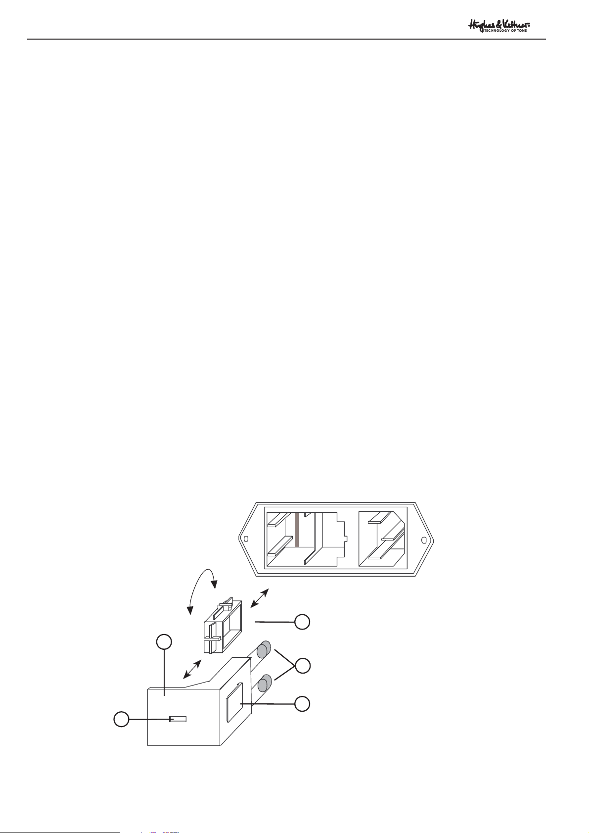
2.1 AC POWER AND
THE GLOBAL CURRENT ADAPTER
NOTE: Before plugging into the wall socket, make certain
the amp is set to the proper voltage for your locale. You can
read the amp's voltage setting in the Voltage Selector
window found on the back of the unit. Also check the fuse
specifications printed above the amp's power cord socket,
and ensure that the fuses you are using have the correct
value for your local current.
TriAmp can operate at AC currents of 230 volts, 115 volts or
100 volts. Use the VOLTAGE SELECTOR to adjust the
voltage accordingly (see Diagram 1):
- Press the fuse's safety latch (1) towards the window (3) with
a small screwdriver and remove it with the two fuses.
- Pull the cartridge (4) out of its socket.
- Rotate the cartridge (4) and plug it back into the socket so
the desired voltage is legible.
- Replace the previously mounted fuses (5). Make certain the
values of your fuses are identical to those required for your
local voltage. The values are specified above the amp's
power cord socket.
- Reinsert the fuse cartridge (2) with the new fuses (5).
- Before you plug into the wall socket, check again to ensure
the correct voltage rating is legible in the VOLTAGE
SELECTOR window (3).
MAINS IN / VOLTAGE SELECTOR
4
2
5
1
3
Page 6
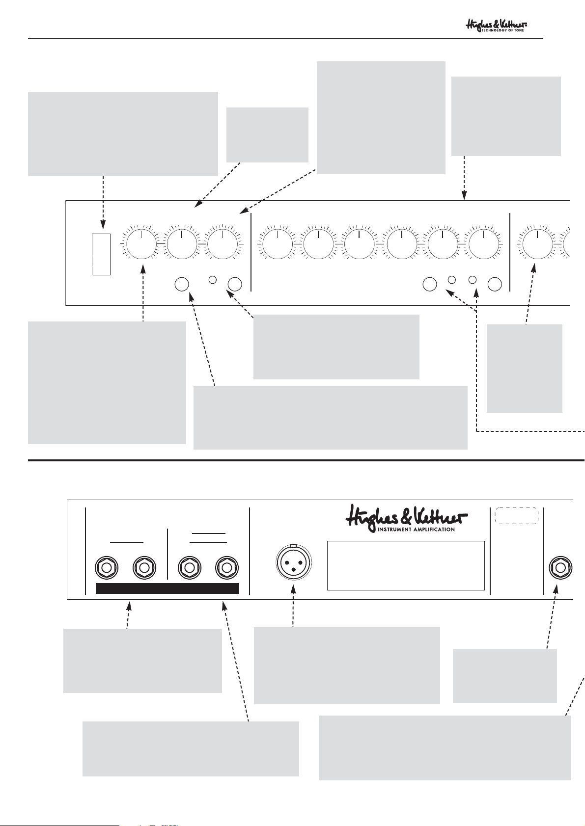
2.2 OVERVIEW OF CONTROL FEATURES
FRONT PANEL:
6
TRIAMP - Manual
STANDBY
MIDI LEARN
MASTER
0510
FX-MIX
FX LOOP
DRY WET
TREBLE
0510
AMP 3 MASTER
-50+5
MID
-50+5
AMP 3
BASS
-50+5
GAIN B
0510
CHANNEL B
GAIN A
0510
CHANNEL A
AMP 2 MASTER
T
-5
0510
0
5
10
PRESENCE
NEVER USE AMP WITHOUT SPEAKERS CONNECTED!
3= 2= +
1= GND
SPEAKERS
1 x 4 OHMS
2 x 8 OHMS
1 x 8 OHMS
2 x 16 OHMS
RED BOX
DI OUT
MADE IN ST. WENDEL / GERMANY
1 x 16 OHMS
FX
SEND
Ser. No.
AMP 3:
The third all-tube amp's
control section. These
controls are comparable
to AMP 2's controls.
AMP 2 MASTER:
Regulates the
volume of AMP 2
in relation to
AMP 1 and AMP
3.
FX LOOP
SWITCH:
Turns TriAmp's FX LOOP on or off. If
you want to switch the FX LOOP on
and off via the STAGEBOARD or MIDI,
set this switch to the 'off' position.
FX-MIX:
Controls the mix of two
signals in relation to each
other, namely TriAmp's
internal preamp signal on the
one hand, and the external
signal fed to the FX RETURN
JACK, usually from an effects
processor, on the other.
MIDI LEARN:
Installation of the MSM-1 MIDI Module is a prerequisite for
MIDI capability. With the module installed, a press on the MIDI
LEARN button will save the current CHANNEL/FX LOOP
combination.
MASTER:
Determines overall
TriAmp output.
PRESENCE:
Determines presence levels for all
three amps. The PRESENCE circuit is
automatically reconfigured with each
change of channel to respond
optimally for each basic sound. Try
it. In each channel, turn the
PRESENCE control all the way up
and back down again to hear how it
affects each channel differently.
STANDBY:
Mutes the amp during breaks. The voltage to
the power amp tubes is reduced but not
turned completely off to extend tube life;
when you turn the amp back to full power,
they are still warm and don't need to be
reheated from a cold start.
FX SEND:
Connect this jack to
your effects processor's
input jack.
-10 db SWITCH:
This damping switch allows you to adapt the signal level to
lower-level effects devices. Press this switch in for
instrument level processors (e.g. stomp boxes).
RED BOX DI OUT:
This is a balanced output featuring the RED
BOX Cabinet Simulator. It enables you to
feed the TriAmp signal directly to a mixing
console for stage and recording purposes.
Refer to Section 4.3 for details.
8 - 16 OHM SPEAKER JACKS:
Dual jacks wired in parallel for speaker cabinets
with an overall impedance between 8 and 16
ohms.
4 OHM SPEAKER JACKS:
Dual jacks wired in parallel for
speaker cabinets with an overall
impedance of 4 ohms.
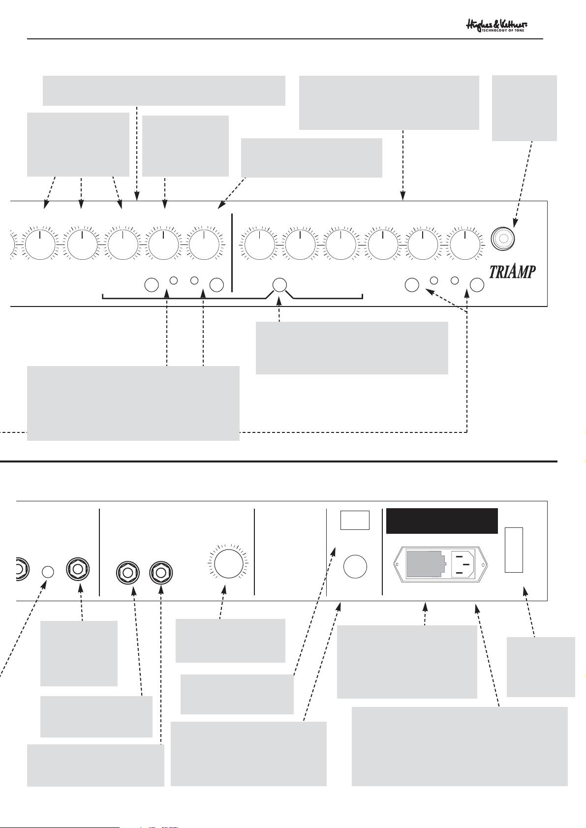
REAR PANEL:
Page 7
7
TRIAMP - Manual
-50+5 -50+5 -50+5
AMP 2
CHANNEL B
0510
GAIN BBASS
CHANNEL A
GAIN A
0510
AMP 1 MASTER
0510
TIGHT
TREBLE
-50+5
INPUT
GAIN BBASSMID GAIN A
AMP 1
CHANNEL ACHANNEL B
05100510-50+5-50+5
MID
MAINS
ON
CAUTION!
TO PREVENT THE RISK
OF FIRE AND SHOCK
HAZARD DON´T EXPOSE
THIS APPLIANCE TO
MOISTURE OR RAIN.
DO NOT OPEN CASE;
NO USER SERVICEABLE
PAR TS INSIDE.
REFER SERVICING TO
QUALIFIED SERVICE
PERSONNEL.
- 10 dB
ND RETURN
REVERB
0510
RETURNSEND
ANODE FUSE:
0.5 AT
50 - 60 Hz. MAX. POWER CONSUM. 440 VA
MAINS IN + VOLTAGE SELECTOR:
230 V~= 2 AT / 100V~= 5 AT /
117 V~= SB 4000 mA
FUSE: BE SURE TO USE CORRECT TYPE + RATING
STAGEBOARD
OFF
Fig.2
Fig.3
AMP 1:
This is the control section for the first of
the three all-tube amps. These controls
are comparable to AMP 2's controls.
AMP 2:
The second all-tube amp's control section.
MAINS:
Power ON/OFF
switch.
INPUT:
Input jack for
guitars.
CHANNEL SELECTOR SWITCHES:
Use this switch to select the desired basic sound
(channel) directly.
INDICATOR LEDS:
These show which basic sound (channel) is
currently active.
TIGHT:
Tightens up response in AMP 1 and AMP 2
for a very direct feel.
GAIN A:
Controls the degree of distortion
in CHANNEL A (AMP 2)
GAIN B:
Controls the degree
of distortion in
CHANNEL B
(AMP 2).
EQ SECTION:
Common BASS, MID
and TREBLE pots for
CHANNEL A and
CHANNEL B.
MAINS IN:
Socket for the included Euromains power cable.
Before plugging into the wall socket, make certain
the amp's voltage rating as displayed in the
VOLTAGE SELECTOR window matches your local
AC voltage rating.
VOLTAGE SELECTOR:
If you need to change TriAmp's
voltage to your local AC voltage
rating, pull out this cartridge and
see Section 2.1 for further
details.
ANODE FUSE:
Fuse holder for the power amp's
anode fuses. Be sure you only use
fuses rated to the indicated
specifications.
STAGEBOARD:
Input jack for TriAmp
STAGEBOARD.
REVERB CONTROL:
Determines the level of
internal reverb.
REVERB SEND:
Jack connected to the
reverb's input.
REVERB RETURN:
Jack connected to the reverb's
output.
FX RETURN:
Connect this jack
to your effects
processor's output
jack.
Page 8
LOOP never compromises the amp's sound quality.
NOTE: As a rule of thumb, the best method for using signal
processors is to set the output of the processor itself to
maximum effect (balance = 100%), and then mix the
processed signal with the original signal via the FX-MIX
control to avoid the sound degradation an effects device
might otherwise introduce.
Switch the FX LOOP button on the front panel to OFF if you
want to switch the FX LOOP via the STAGEBOARD or MIDI
commands.
Connecting signal processors:
- Connect the device's INPUT to the FX LOOP SEND jack
and its OUTPUT to the RETURN jack.
- Activate the FX LOOP via the FX LOOP button on the front
panel or the STAGEBOARD.
- Adapt the FX loop level to the signal processor's level, if
necessary. Press the -10 db button for effects devices like
stomp boxes that are designed for guitar signals. If the button
is not depressed, the signal level remains at standard line
level, appropriate for most rack-mounted multi-effects
processors.
- Adjust the relative volumes of the original and processed
signals via the FX MIX pot located on the front panel
(towards DRY = more original signal, towards WET = more
processed signal).
NOTE: Some signal processors cause phase cancellations
that are detrimental to the overall sound. If this is the case,
turn the FX control all the way to the right (WET). The effects
loop now operates as a conventional serial loop, i.e. the
volume relationship between the original and the processed
signal must be adjusted at the processor.
TIP 1: If you choose not to connect a signal processor or
effects device to the FX loop, you may connect another
instrument or audio source. When you use the RETURN
circuit as a second input channel in this way, the FX-MIX
knob becomes a balance control to determine the relative
volumes of the guitar signal and the other sound source.
TIP 2: Another option is open to you if you are not using a
signal processor. Use the loop, with nothing connected to it,
as a second master volume. Simply activate the FX loop and
dial in a separate master volume setting via the FX MIX pot
(to the left towards DRY = volume up, to the right towards
WET = volume down). Now use the FX LOOP on/off switch
to cut back and forth between the two master volumes.
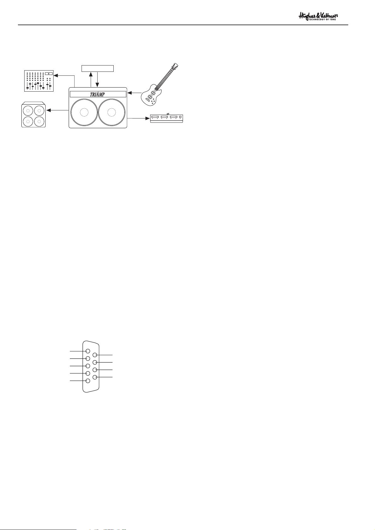
3.0 STANDARD SETUP /
CABLE CONNECTIONS
4.0 TRIAMP OPERATION
4.1 CHANNEL SELECTION
The six basic sounds/channels of the TriAmp can be
accessed via DSS (Direct Sound Switching). Simply press the
appropriate CHANNEL SELECTOR switch.
This applies to the CHANNEL SELECTOR switches located
on the front panel as well as those on the STAGEBOARD.
You can also execute switching functions via MIDI using the
MSM 1 MIDI Module (refer to Section 4.4).
If you want to use an external MIDI switcher, you will need
to make an adapter cable that accesses the Stageboard jack,
wiring it according to the pin assignments shown in Diagram
5. Channel selection is executed via momentary contact; FX
LOOP activation is executed by switching, namely by
applying pin 8 to pin 5 (ground).
Stageboard jack pin assignments:
4.2 TRIAMP AND SIGNAL PROCESSORS
TriAmp is equipped with a parallel effects loop. The
processed signal is mixed with the internal preamp's original
signal in such a way that the original signal remains audible
even during the brief lags caused by multi-effects processor
switching. The FX-MIX knob controls the dry/wet mix.
The passive nature of the FX MIX guarantees that the original
signal is not sent through any solid-state circuitry. When the
FX LOOP is deactivated, the buffer stage for the effects side
is switched off via a relay, thereby ensuring that the FX
8
TRIAMP - Manual
FX-UNIT
INPUT
SEND RETURN
RED BOX
DI OUT
SPEAKER
OUT
MIXER
GUITAR CABINET
STAGEBOARD
STAGEBOARD
Fig.4
Fig.5
Ground/Masse
Amp 3A
Amp 3B
FX-LOOP
+ 22 V Output
Amp 2B
Amp 2A
Amp 1B
Amp 1A
Page 9

1's socket so that the color-coded wire faces the notch on
the socket.
MSM-1 socket and indicator notch.
- Insert the MSM-1 into the module port, and affix it in place
using the same four screws you just removed a moment ago.
Make sure the writing on the MSM-1 reads in the same
direction as that on the rest of the chassis back.
Location of the sockets.
- On the control circuit board you will find the socket for the
connector on the other end of the ribbon cable. Also insert
this connector in the socket so that the color-coded wire
faces the notch on the socket.
- Double-check that the module and the connectors are
seated correctly.
- Replace the chassis in the housing and, if you removed the
tubes, the tubes in the chassis.
- Replace the amp's rear panel, and reconnect the cables to
the reverb and speakers.
- To use the MIDI LEARN function with the TriAmp, please
refer to the instructions included with the MSM-1 MIDI
Module. The moment power is applied to the amp, the MIDI
functions of the TriAmp are immediately available. Please
check all switching functions of the amp.
9
TRIAMP - Manual
Abb.7
4.3 THE RED BOX DI OUT
- ALL-TUBE TONE TO THE MIXER
The balanced RED BOX DI OUT allows you to connect
TriAmp's output signal directly to a mixing console, for the
smooth, rich sound of a miked-up cabinet without the
hassles of actually using a microphone. The integrated RED
BOX circuitry is in-line with the speaker output for optimum
audio results, allowing the character of the connected
speaker to come through to as great a degree as possible.
WARNING: Never run the amp without a load (a connected
speaker cabinet), even in a recording situation. Doing so
risks serious damage to the amp's all-tube output stage.
NOTE: Speakers, in combination with a tube amp's output
transformer, may demonstrate microphonic properties. If
your amp's master setting is extremely low and the PA is
very loud, you may encounter feedback through the DI OUT
circuit. This effect does not occur at normal stage volumes.
However, we do recommend you use the STANDBY switch
rather than turning the MASTER down to silence your amp
during breaks.
If this feedback problem does occur at some point, simply
turn the amp's master volume up. The speaker then loses the
microphonic properties and the feedback will stop.
4.4 TRIAMP AND MIDI
With the MSM-1 MIDI Module installed, you can use your
multi-effects processor to select TriAmp channels and turn
the FX LOOP on or off via MIDI.
Installing the MSM-1 MIDI Module
NOTE (VERY IMPORTANT): The following instructions are
intended solely for a factory authorized technician.
- Unplug the amp's mains cord from the wall socket and
remove all connected cables (e.g. to the spring reverb or
speakers).
- Remove the amp's rear panel cover so you can access the
tubes.
- Prepare a suitable spot to set the amp chassis (for instance
two books placed the same distance apart as the two
transformers), or remove the power amp tubes.
- Remove the four retaining screws that hold the chassis in
place, and carefully pull the amp chassis out of the wood
housing.
- Remove the MIDI Module port cover plate from the rear
panel of the chassis.
- Insert the included flat cable connector plug in the MSM-
Abb.6
MSM-1
REVERB FX OUTPUT
Page 10

10
TRIAMP - Manual
5.0 REPLACING TUBES, SERVICE AND
PREVENTIVE MAINTENANCE
TriAmp features factory-equipped 6L6GC, 12AX7A and
E83CC Hughes & Kettner tubes. Hughes & Kettner tubes are
first burned in and then checked for their electrical and
mechanical properties (microphonics), selected and
matched, and then given a final audio and response test
once they have been installed in a completed TriAmp.
One of the most important steps in the testing process is
power tube matching, i.e. selecting and pairing tubes with
identical characteristics.
When should you replace tubes?
The tubes in your TriAmp are of exceptional quality and will
last extremely long. Old tubes begin to show signs of wear
such as increased microphonics and noise, treble loss, weak
power output, muddy sound, etc. Power amp tubes wear out
faster than preamp tubes. If you encounter these problems,
replace the tubes. Not only do old tubes impair the sound,
they are also prone to fail altogether.
NOTE: We recommend you refrain from exchanging tubes
solely for sound experimentation purposes. First of all, this
may end up damaging your amp. Besides, we tested every
conceivable tube option and installed the tube types for the
best possible performance.
Keep the following in mind when you are ready to
replace tubes.
- We recommend only qualified service personnel replace
tubes.
- Before removing the rear panel cover, make certain the
mains cord is unplugged from the wall socket!
- Use only matched pairs of power amp tubes. You may use
5881 (6L6GC-R) tubes instead of the 6L6GC tubes for an
even heavier sound, but, again, only in matched pairs.
- For tonal reasons, we distinguish between 12AX7A and
E83CC preamp tubes. The E83CC is a high-grade version of
the ECC83, a common tube in Western Europe. The E83CC
tube is built by another manufacturer; it features a different
design and subsequently sounds different. In principle, you
may use certain tubes other than those specified on the
chassis in a pinch, but TriAmp sound quality will not be at
its full potential.
- A hum adjustment must be made every time tubes are
replaced. Activate AMP 2, CHANNEL B and AMP 3,
CHANNEL B and set the lowest noise levels via the trimmer.
- Select input tubes with minimal microphonic properties
and lowest noise levels by conducting a simple listening test.
- As a rule, the amp will not absolutely need to be re-biased
with each new set of tubes, assuming you use a matched set.
Biasing is complex procedure requiring special tools and
should only be done by a qualified amp specialist.
How can you extend the life of your tubes?
- Use the STANDBY SWITCH! The more often the tubes are
heated up, the shorter their life span will be. The standby
feature switches the anode voltage off and reduces actual
operating time. Avoid mechanical shocks, especially when
the amp is on. Switch the amp off and let the tubes cool
down before transport. A quality flight case is a good
investment and is only slightly more expensive than a
complete set of tubes.
- Proper bias and trim extend the life of your tubes. If you
find the tubes need to replaced too often, consult a qualified
technician.
All other TRIAMP components do not require maintenance.
Use a soft slightly damp cloth for all exterior parts. Avoid
exposure to mechanical shocks, extreme heat, dust and
moisture. Ensure the cooling vents at the top of the housing
are not obstructed during operation.
Page 11

11
TRIAMP - Manual
6.0 TROUBLESHOOTING
TriAmp is not getting any power:
- Check the mains cable to see if it is connected properly.
- The mains fuse is defective. Replace the fuse with another
identical fuse.
TriAmp is connected properly, but no sound is audible:
- The amp is set to STANDBY.
- One or several GAIN and MASTER controls are turned all
the way down. Dial in a higher setting.
- The FX-MIX control is turned all the way to WET but you
have not connected a processor to the FX loop. Switch the
FX LOOP off or turn the FX-MIX knob to DRY.
- The anode fuse is blown. Before you replace the fuse,
examine whether the power amp tubes are defective.
Fuse keeps on blowing.
- After replacing the fuse, with standby off, turn on the
power. Watch the power tubes, turn standby on. Look for
tube “flash” before fuse blows, indicating excess oxygen
within the tube. This will show which power tube needs to
be replaced.
The FX LOOP is on when it shouldn’t be.
- The FX LOOP is deactivated when the front panel button,
the STAGEBOARD button and the MIDI module switching
function are off. If any of these three switches is on, the
circuit is active.
The sound is thin and muddy when the effects processor is
active.
- The signal processor is causing phase cancellations that are
being added to the original signal in the parallel loop. To
avoid phase cancellations, turn the FX-MIX control all the
way to the right (WET), and adjust the mix at the processor
itself.
When in use with a loud PA, the RED BOX DI OUT circuit is
causing feedback even though the amp is set to a low
MASTER volume.
- Speakers connected to a tube amp may have microphonic
properties. Turn TriAmp’s MASTER volume up and the circuit
will stop feeding back. In extreme cases of microphonic
speakers, you would either turn the PA down or mic the
cabinet.
Your amp is producing ringing noises or tends to feedback.
- One or several tubes are microphonic. Replace the
appropriate tube with another of the same type.
After just a few hours of operation, your amp is displaying
the typical characteristics of old tubes (increased
microphonics and noise, treble loss, weak power output,
muddy sound).
- You have installed the wrong tubes or the bias is not
adjusted properly. Take the amp to a professional amp
technician to correct the problem.
Page 12

12
TRIAMP - Manual
Page 13

INHALT Seite
WICHTIGE SICHERHEITSHINWEISE 2
1.0 DIE “DREI AMPS” IM TRIAMP 14
2.0 ANSCHLÜSSE UND BEDIENELEMENTE 15
2.1 NETZANSCHLUSS UND
WELTSPANNUNGSADAPTION
2.2 ÜBERSICHT DER BEDIENELEMENTE 16
3.0 STANDARD SET UP / VERKABELUNG 18
4.0 BEDIENUNG DES TRIAMP
4.1 DAS ANWÄHLEN DER KANÄLE
4.2 DER TRIAMP MIT EFFEKTGERÄTEN
4.3 RED BOX DI OUT - VOLLRÖHRE AM 19
MISCHPULT
4.4 DER TRIAMP UND MIDI
5.0 RÖHRENTAUSCH, WARTUNG UND PFLEGE 20
6.0 FEHLERBESEITIGUNG / TROUBLESHOOTING 21
7.0 TECHNISCHE DATEN 23
13
TRIAMP - Manual
Herzlichen Glückwunsch zu Deiner
Entscheidung für den TRIAMP.
Während der vergangenen 40 Jahre sind tausende
verschiedener Gitarrenamps auf den Markt
gekommen, von denen sich einige wenige zu
begehrten Klassikern entwickelt haben.
Tonqualität und die Reaktion auf die Spielweise
machen diese Klassiker zu einzigartigen, zeitlosen
Instrumenten, die zu hohen Preisen gehandelt
werden.
Mit großem Respekt vor diesen Klassikern, gelingt
es dem TriAmp dennoch deren Einschränkungen
zu überwinden. Wie die klassischen Vorbilder
verwendet der TriAmp im Signalweg
ausschließlich “klassische” Bauteile wie VakuumRöhren und Widerstände. Aber die neuentwickelte
Technologie des Triamp benutzt und verschaltet
diese zeitlosen Bauelemente auf eine
vollkommen einzigartige Weise. Das Resultat ist
eine Soundvielfalt, die für einen Vollröhrenamp
bisher absolut unerreichbar war. Der TriAmp bietet
dem Röhrenpuristen zum ersten Mal in der
Geschichte drei völlig unabhängige Verstärker in
einem Gerät: Vergangenheit, Gegenwart und
Zunkunft der Röhrensounds
.
Viel Spaß mit dem TRIAMP!
Das Hughes & Kettner-Team
Page 14

14
TRIAMP - Manual
1.0 Die drei Amps im TRIAMP
Drei grundverschiedene Verstärker in einem Gerät - ein
Wunschtraum, der bisher unerfüllbar erschien. Nach Jahren
intensiver Entwicklungsarbeit und Soundforschung wird mit
dem TRIAMP diese Kombination zum ersten Mal
Wirklichkeit. Dazu entwickelte das HUGHES & KETTNER
Team eine neue Schaltungstechnologie die vollkommen
eigenständige Grundsounds in höchster Qualität ermöglicht.
Jeder dieser Verstärker ist zweikanalig aufgebaut und so
stehen insgesamt 6 Sounds auf Knopfdruck zur Verfügung.
AMP 1
Klassische “Clean”- Sounds sind die Hauptaufgabe des
ersten Amps. Ursprünglich einmal entwickelt um einen
möglichst klaren und sauberen Sound zu liefern, entdeckten
kreative Gitarristen bald das veränderte Klangverhalten im
Vollastbereich als eigene Soundqualität. Genau dieses
Verhalten zeichnet AMP 1 aus. CHANNEL A klingt voll und
rund, er übersteuert sehr weich und breitbandig .
CHANNEL B ist “knackiger”, schon kleinere GAIN
Einstellungen liefern prägnante Obertöne im
Hochmittenbereich - ideal für Pickings und “lebendige”
Arpeggios. Selbstverständlich liefern beide Kanäle bei
entsprechenden Gaineinstellungen auch “echte”
Cleansounds. Die TIGHTSCHALTUNG wirkt deutlich auf
das Spielgefühl beim Anschlag - die Ansprache wird dichter
und direkter.
AMP 2
Hohe Dynamik und völlige Kontrolle bei jedem
Übersteuerungsgrad bietet der zweite Amp. Dieses
Verhalten eröffnet enorme Ausdrucksmöglichkeiten und
erlaubt eine nuancierte Umsetzung von Spieltechniken.
Detailgetreu überträgt der Amp jeden Anschlag und selbst
kleinste Verzierungen - weshalb der Begriff “ehrlich” uns als
besonders treffend erscheint.
CHANNEL A hat einen sehr offenen, englischen Charakter,
der rauhe Begleitung und durchsetzungskräftiges
Akkordspiel wirkungsvoll unterstützt. CHANNEL B klingt mit
zunehmender Übersteuerung “dicker” und trägt mit mehr
Sustain den Ton - der Amp “singt”. Auch im AMP 2 wirkt
die TIGHTSCHALTUNG auf das Attack.
AMP 3
Präzise Distortionsounds spielen bei der Entscheidung für
einen Verstärker eine besonders große Rolle. Ein
verbindliches Kriterium für Top-Class-Gitarrenverstärker:
selbst bei extremem Gaineinstellungen sollte der
Gitarrencharakter hörbar und der Ton definiert bleiben. Nur
wenige Verstärker können diesen Anspruch erfüllen
- AMP 3 gehört sicherlich zu den Anführern dieser Elite!
Der Leadsound in CHANNEL A ist sehr ehrlich und direkt, dynamisch reagiert er auf Anschlagstärke und Volumenpoti
der Gitarre . Ein Solokanal für “Kämpfernaturen” und
gleichzeitig optimal für druckvolle Powerchords mit “Brett”.
CHANNEL B liefert High Gain ohne Ende - mit singenden
Mitten, die dem Solo Durchsetzungskraft und Prägnanz
verleihen.
Wie realisiert der TRIAMP so verschiedene Grundsounds mit
nur einer Endstufe und einer gemeinsamen Mastersektion ?
Sein Soundpotential schöpft der Triamp zum großen Teil aus
seiner puristischen Röhrentechnik. Eine hochentwickelte
Verschaltung der Röhrenstufen - bei jedem Soundwechsel in
neuer Konfiguration - ermöglicht diese enorme
Soundflexibilität ohne Einsatz von Halbleiterschaltungen,
die den Sound verfälschen könnten. Auch das
Endstufenkonzept trägt entscheidend zur Klangvielfalt des
TRIAMP bei: Neben einer Anpassung der Presenceschaltung
wird jedem der sechs Grundsounds beim Umschalten auch
ein eigener Dämpfungsfaktor in der Endstufe zugeordnet.
GAIN A
0510
CHANNEL A
AMP 2 MASTER
5
0
10
STANDBY
PRESENCE
0510
MASTER
0510
MIDI LEARN
FX-MIX
DRY WET
FX LOOP
AMP 3 MASTER
0510
TREBLE
-50+5
MID
-50+5
AMP 3
BASS
-50+5
GAIN B
0510
CHANNEL B
TREBLE
-50+5
MID
0
+5 -50+5
-5
AMP 2
GAIN BBASS
0510
CHANNEL B
GAIN A
0510
CHANNEL A
AMP 1 MASTER
0510
TREBLE
-50+5
TIGHT
GAIN BBASSMID GAIN A
AMP 1
INPUT
05100510-50+5-50+5
CHANNEL ACHANNEL B
Page 15

15
TRIAMP - Manual
Abb.1
2.0 ANSCHLÜSSE UND BEDIENELEMENTE
2.1 NETZANSCHLUSS UND
WELTSPANNUNGSADAPTION
HINWEIS: Stelle vor dem Anschluß des TRIAMP
sicher, daß die vorhandene Netzspannung mit
dem im Sichtfenster des VOLTAGE SELECTORS
angegebenen Spannungswert übereinstimmt.
Überprüfe auch die Sicherungswerte entsprechend
dem Aufdruck nahe der Anschlußbuchse.
Der TRIAMP kann an den Netzspannungen 230 V, 115 V
und 100 V betrieben werden. Die Anpassung erfolgt mittels
des in die Netzbuchse integrierten VOLTAGE SELECTORS.
Dazu wird wie folgt vorgegangen (siehe Abb.1):
- Mittels eines kleinen Schraubenziehers die Sperre (¿) des
Sicherungshalters (≠) in Richtung Sichtfenster (¬) drücken
und diesen zusammen mit den beiden Sicherungen
herausziehen.
- Den Steckeinsatz (Ø) herausziehen.
- Der Steckeinsatz (Ø) wird so gedreht und wieder
eingesteckt, daß der Aufdruck der gewünschten
Netzspannung nach außen zeigt.
- Die vorher montierten Sicherungen (∞) werden ersetzt.
Verwende nur den nahe der Anschlußbuchse aufgedruckten
Sicherungswert, der für die neue Netzspannung vorgesehen
ist!
- Den Sicherungshalter (≠) zusammen mit den neuen
Sicherungen (∞) einsetzen.
- Vor dem Netzanschluß nochmals prüfen, ob der richtige
Spannungswert im Sichtfenster (¬) des VOLTAGE
SELECTORS erkennbar ist.
MAINS IN / VOLTAGE SELECTOR
4
2
5
1
3
Page 16

16
TRIAMP - Manual
STANDBY
MIDI LEARN
MASTER
0510
FX-MIX
FX LOOP
DRY WET
TREBLE
0510
AMP 3 MASTER
-50+5
MID
-50+5
AMP 3
BASS
-50+5
GAIN B
0510
CHANNEL B
GAIN A
0510
CHANNEL A
AMP 2 MASTER
T
-5
0510
0
5
10
PRESENCE
NEVER USE AMP WITHOUT SPEAKERS CONNECTED!
3= 2= +
1= GND
SPEAKERS
1 x 4 OHMS
2 x 8 OHMS
1 x 8 OHMS
2 x 16 OHMS
RED BOX
DI OUT
MADE IN ST. WENDEL / GERMANY
1 x 16 OHMS
FX
SEND
Ser. No.
2.2 ÜBERSICHT DER BEDIENELEMENTE
Front/ Rear
AMP 3:
Bediensektion des
dritten Vollröhrenamps.
Die Funktionen dieser
Regler sind mit denen
des AMP 2 vergleichbar.
AMP 2 MASTER:
Regelt die Lautstärke des AMP
2 im Verhältnis
zu AMP 1 und
AMP 3.
FX LOOP SCHALTER:
Aktiviert den Effektweg des TRIAMP.
Soll diese Schaltfunktion via STAGEBOARD oder MIDI erfolgen, ist der
Schalter in Position “aus” zu bringen.
FX-MIX:
Bestimmt das
Lautstärkeverhältnis
zwischen dem TRIAMP
VORSTUFENSIGNAL und
dem Signal an der FX
RETURNBUCHSE - z.B.
von einem eingeschleiften
Effektgerät.
MIDI LEARN:
Erst mit der Installation des MSM-1 Moduls wird der TRIAMP
midifähig. Die MIDI LEARN Taste speichert dann auf einfachen
Knopfdruck die aktuelle CHANNEL- / FX LOOP-Kombination.
MASTER:
Kontrolliert die
Gesamtlautstärke
des TRIAMP.
PRESENCE:
Regelt Presence für AMP 1, AMP 2,
und AMP 3.
Die grundsoundspezifische Umschaltung
des PRESENCE bewirkt eine für alle
Kanäle optimierte Arbeitsweise. Dies ist
am besten nachvollziehbar, wenn einmal
in jedem Kanal PRESENCE voll
aufgezogen und wieder abgedreht wird die unterschiedliche Wirkungsweise wird
so hörbar.
STANDBY:
Dient zur Stummschaltung des Gerätes in
Spielpausen.
Die Endstufenröhren werden im Standbybetrieb
geschont, ohne daß bei Wiederinbetriebnahme
die Röhren erneut aufgeheizt werden müssen.
FX SEND:
Verbinde diese Buchse
mit dem Eingang des
Effektgerätes.
-10dB WAHLSCHALTER:
Dämpfungsschalter zum Anpassen des Effektgerätes an die
TRIAMP VORSTUFE. Bei Verwendung von Effektgeräten,
deren Eingang für Instrumentenpegel ausgelegt ist diesen
Schalter bitte in gedrückte Position bringen.
RED BOX DI OUT:
Symmetrischer Ausgang der im
TRIAMP integrierten RED BOX LAUTSPRECHERSIMULATION zum Mischpult für Live- und Recordingzwecke.
Beachte hierzu auch Kapitel 4.3!
8-16 OHM SPEAKER BUCHSEN:
Parallel geschaltetes Buchsenpaar zum Anschluß
von Lautsprecherboxen, deren Gesamtimpedanz
zwischen 8 Ohm und 16 Ohm liegt.
4 OHM SPEAKER BUCHSEN:
Parallel geschaltetes Buchsenpaar
zum Anschluß von Lautsprecherboxen, mit einer Gesamtimpedanz
von 4 Ohm.
Page 17

17
TRIAMP - Manual
-50+5 -50+5 -50+5
AMP 2
CHANNEL B
0510
GAIN BBASS
CHANNEL A
GAIN A
0510
AMP 1 MASTER
0510
TIGHT
TREBLE
-50+5
INPUT
GAIN BBASSMID GAIN A
AMP 1
CHANNEL ACHANNEL B
05100510-50+5-50+5
MID
MAINS
ON
CAUTION!
TO PREVENT THE RISK
OF FIRE AND SHOCK
HAZARD DON´T EXPOSE
THIS APPLIANCE TO
MOISTURE OR RAIN.
DO NOT OPEN CASE;
NO USER SERVICEABLE
PAR TS INSIDE.
REFER SERVICING TO
QUALIFIED SERVICE
PERSONNEL.
- 10 dB
ND RETURN
REVERB
0510
RETURNSEND
ANODE FUSE:
0.5 AT
50 - 60 Hz. MAX. POWER CONSUM. 440 VA
MAINS IN + VOLTAGE SELECTOR:
230 V~= 2 AT / 100V~= 5 AT /
117 V~= SB 4000 mA
FUSE: BE SURE TO USE CORRECT TYPE + RATING
STAGEBOARD
OFF
Abb.2
Abb.3
AMP 1:
Bediensektion des ersten Vollröhrenamps. Die Funktionen dieser Regler sind
mit denen des AMP 2 vergleichbar.
AMP 2:
Bediensektion des zweiten Vollröhrenamps.
MAINS:
Netzschalter.
INPUT:
Eingang zum
Anschluß der
Gitarre.
SOUNDSWITCHES:
Wählen direkt den gewünschten Grundsound
(CHANNEL) an.
INDIKATOR LEDS:
Zeigen den aktiven Grundsound (CHANNEL) an.
TIGHT:
Bewirkt eine “knackige” Ansprache und
damit ein sehr direktes Spielgefühl für AMP
1 und AMP 2.
GAIN A:
Regelt den Übersteuerungsgrad
des CHANNEL A (AMP 2).
GAIN B:
Regelt den Übersteuerungsgrad des
Channel B (AMP 2).
KLANGREGELUNG:
Gemeinsame BASS,
MID und TREBLE Regler für CHANNEL A
und CHANNEL B.
MAINS IN:
Netzbuchse für das mitgelieferte Euronetzkabel.
Bevor der Netzstecker eingesteckt wird,
vergewissere Dich, daß die vorhandene
Netzspannung mit dem im Fenster des VOLTAGE
SELCTORS angegebenem Wert übereinstimmt.
VOLTAGE SELECTOR:
Steckeinsatz zur Anpassung des
TRIAMP an die vorhandene
Netzspannung. Beachte hierzu
auch Kapitel 2.1!
ANODE FUSE:
Sicherungshalter für die Anodensicherung der Endstufenröhren.
Den aufgeruckten Sicherungswert
unbedingt beachten!
STAGEBOARD:
Anschlußbuchse für das
TRIAMP STAGEBOARD.
REVERB REGLER:
Regelt den Anteil des
integrierten Halleffektes.
REVERB SEND:
Anschlußbuchse zum
Input der HALLSPIRALE.
REVERB RETURN:
Anschlußbuchse vom Output
der HALLSPIRALE.
FX RETURN:
Verbinde diese
Buchse mit dem
Ausgang des
Effektgerätes.
Page 18

Mischungsverhältnis kann am FX-MIX Regler individuell
eingestellt werden.
Die passive Mischung stellt dabei sicher, daß das
Originalsignal keinerlei Halbleiter durchläuft. Bei
deaktiviertem Effektweg wird die Bufferstufe für die
Effektseite per Relais weggeschaltet. Eine Beeinträchtigung
der Soundqualität des TRIAMP durch den Effektweg ist somit
ausgeschlossen.
HINWEIS: Prinzipiell werden mit Effektgeräten die besten
Soundergebnisse erzielt, wenn die Mischung Original- /
Effektsignal mittels des FX-MIX Reglers erfolgt, und am
Effektgerät ein möglichst großer Effektanteil programmiert
wird. Somit werden Soundverluste durch das Effektgerät
vermieden.
Beachte, daß der FX LOOP SCHALTER auf der Frontplatte
deaktiviert sein sollte, wenn mit dem Stageboard oder via
MIDI umgeschaltet wird.
Anschluß des Effektgerätes:
- Verbinde die SEND Buchse mit dem INPUT und die
RETURN Buchse mit dem OUTPUT des Effektgerätes.
- Aktiviere den Effektweg mittels des FX LOOP Schalters auf
der Frontplatte oder dem Stageboard.
- Passe den Effektweg auf den Eingangspegel des
Effektgerätes an. Für Effektgeräte, deren Eingang auf
Gitarrenpegel ausgelegt ist, sollte der -10dB SCHALTER
gedrückt sein. Ist der Schalter nicht gedrückt, arbeitet der
Effektweg auf dem für Multieffektgeräte üblichen Linepegel.
- Stelle über den FX-MIX Regler das Mischungsverhältnis
von Original- und Effektsignal ein (Richtung DRY = mehr
Originalsignal, Richtung WET = mehr Effektsignal).
HINWEIS: Manche Effektgeräte verursachen
Phasenverschiebungen, die den Gesamtsound nachteilig
verändern. Drehe in diesem Fall FX-MIX ganz nach rechts
(WET). Der Effektweg arbeitet jetzt wie ein konventioneller
serieller Effektweg, d.h. das Lautstärkeverhältnis zwischen
Original- und Effektsignal wird am Effektgerät eingestellt.
TIP 1: Ist kein Effektgerät am Effektweg eingeschleift, so läßt
sich die RETURN Bchse zum Anschluß eines zweiten
Instrumentes oder beliebiger Audioquellen verwenden.
Wenn der RETURN als Zweitkanal benutzt wird, bestimmt
der FX-MIX Regler die Lautstärkebalance zwischen Gitarre
und zusätzlicher Signalquelle.
TIP 2: Ist kein Effektgerät eingeschleift, läßt sich der FXLOOP zum Abrufen einer zweiten Masterlautstärke nutzen.
Dazu wird bei aktiviertem Effektweg am FX-MIX Regler die
zweite Lautstärke eingestellt (Richtung DRY=lauter, Richtng
WET=leiser). Mit dem FX LOOP SCHALTER läßt sich nun
zwischen beiden Lautstärken umschalten.
3.0 STANDARD SET UP / VERKABELUNG
HINWEIS: Niemals den TRIAMP ohne angeschlossenen
Lautsprecher betreiben!
4.0 BEDIENUNG DES TRIAMP
4.1 DAS ANWÄHLEN DER KANÄLE
Die sechs Grundsounds (CHANNELS) des TRIAMP können
per DSS (Direct Sound Switching) angewählt werden. Diese
Schaltung ermöglicht ein extrem komfortables Umschalten
durch einfachen Druck auf den entsprechenden
SOUNDSWITCH.
Dabei kann mit den SOUNDSWITCHES auf der Frontplatte
oder am Stageboard gearbeitet werden.
Weiterhin besteht die Möglichkeit, die Soundumschaltung
vom MSM-1 MIDI Modul ausführen zu lassen (siehe dazu
auch Kapitel 4.4!).
Soll mittels eines externen MIDI Switchers umgeschaltet
werden, so ist mit Hilfe der in Abb.5 gezeigten
Anschlußbelegung ein Adapterkabel anzufertigen. Die
Kanalwahl erfolgt dabei als Tastfunktion, das Aktivieren des
FX LOOP erfolgt als Schaltfunktion für die Verbindung der
Schaltleitung gegen Pin 5 (Masse).
Pinbelegung der Stageboardbuchse
4.2 DER TRIAMP MIT EFFEKTGERÄTEN
Der TRIAMP ist mit einem parallelen Effektweg ausgestattet.
Dabei wird das Effektsignal dem Originalsignal der
TRIAMPVORSTUFE so zugemischt, daß bei korrekter
Einstellung auch während der Umschaltpausen von
Multieffektgeräten das Originalsignal hörbar bleibt. Das
18
TRIAMP - Manual
FX-UNIT
INPUT
SEND RETURN
RED BOX
DI OUT
SPEAKER
OUT
MIXER
GUITAR CABINET
STAGEBOARD
STAGEBOARD
Abb.4
Abb.5
Ground/Masse
Amp 3A
Amp 3B
FX-LOOP
+ 22 V Output
Amp 2B
Amp 2A
Amp 1B
Amp 1A
Page 19

- Entferne die Abdeckplatte des MIDI-Modulschachtes auf
der Rückseite des Chassis.
- Stecke einen Multistecker des Flachbandkabels vorsichtig
in den freien Steckersockel des MSM-1 Moduls, so daß die
farbig gekennzeichnete Ader des Kabels zur
Markierungskerbe des Steckersockels zeigt.
Steckersockel mit Markierungskerbe
- Befestige das MSM-1 im Modulschacht. Benutze dazu die
vier Schrauben der zuvor entfernten Abdeckplatte. Beachte,
daß die Beschriftung des MSM-1 entsprechend der
Beschriftung auf der Chassisrückseite ausgerichtet ist.
Lage der Steckersockel
- Auf der Schalterplatine befindet sich der Steckersockel für
den freien Multistecker. Stecke den Multistecker auch hier so
ein, daß die farbig gekennzeichnete Ader des Kabels zur
Markierungskerbe des Steckersockels zeigt.
- Prüfe den korrekten Sitz des Moduls und der
Steckverbindungen.
- Montiere das Chassis und ggf. die Endstufenröhren.
- Montiere die rückseitige Blende des Amps, sowie Hall- und
Speakerkabel.
- Nach dem Einschalten der Stromversorgung sind die MIDIFunktionen des TRIAMP sofort verfügbar. Bitte überprüfe alle
Schaltfunktionen des Amps.
19
TRIAMP - Manual
Abb.7
4.3 RED BOX DI OUT
- VOLLRÖHRE AM MISCHPULT
HINWEIS: Auch in Recording-Situationen muß an einem der
Lautsprecherausgänge eine Box oder ein geeigneter
Lastwiderstand angeschlossen werden, da sonst die Endstufe
beschädigt werden könnte.
Der symmetrierte RED BOX DI OUT ermöglicht einen
schnellen und direkten Anschluß des TRIAMP an einen
Mischpultkanal. Die integrierte RED BOX ist dabei am
Lautsprecherausgang verschaltet, so daß optimale
Soundergebnisse erzielt werden und auch die Charakteristik
des angeschlossenen Lautsprechers mit einbezogen wird.
HINWEIS: Lautsprecher können in Verbindung mit dem
Ausgangsübertrager eines Röhrenamps wie ein Mikrofon
wirken. Bei extrem kleinen Mastereinstellungen am Amp
und sehr lauter PA kann dies zu Rückkopplungen via DIOUT führen. Bei den üblichen Bühnenlautstärken tritt dieser
Effekt nicht auf. In Spielpausen sollte aber die
Standbyfunktion einem Abdrehen des MASTER immer
vorgezogen werden.
Tritt dieser Effekt doch einmal auf, sollte am Amp die
Masterlautstärke erhöht werden, somit verliert der
Lautsprecher seine Mikrofoneigenschaften und die
Rückkopplung verschschwindet.
4.4 DER TRIAMP UND MIDI
Ist das MSM-1 Modul eingebaut, können die Grundsounds
des TRIAMP und der Effektweg via MIDI geschaltet werden.
Das somit mögliche gleichzeitige Umschalten von TRIAMP
und Multieffektgeräten bedeutet bestmöglichen
Spielkomfort.
Installation des MSM-1 MIDI-Moduls:
HINWEIS: Das MSM-1 Midi-Modul darf nur von einem
erfahrenen Service-Technuker eingebaut werden. Die
nachfolgenden Hinweise sind für den Service-Techniker
gedacht!
- Ziehe den Netzstecker des TRIAMP und entferne alle
Speakerkabel, Kabel zur Hallspirale, etc.
- Entferne die rückseitige Blende des Amps, so daß die
Röhren frei zugänglich sind.
- Bereite (z.B. mittels zweier Bücher im Abstand der Trafos)
eine geeignete Ablage für das Ampchassis vor oder entferne
die Endstufenröhren.
- Entferne die vier Chassisbefestigungsschrauben und ziehe
das Ampchasis vorsichtig nach hinten aus dem
Holzgehäuse.
Abb.6
MSM-1
REVERB FX OUTPUT
Page 20

20
TRIAMP - Manual
5.0 RÖHRENTAUSCH,
WARTUNG UND PFLEGE
Der TRIAMP ist ab Werk mit 6L6GC, 12AX7A und E83CC
Hughes & Kettner Röhren bestückt. Hughes & Kettner
Röhren werden nach dem “Burn-In” (ein erster “Dauerlauf”
unter Last) in aufwendigen Selektionsverfahren auf ihre
elektrischen Werte, mechanische Beschaffenheit
(Mikrofonie), und darüber hinaus im akustischen Test am
fertigen TRIAMP auf ihr Soundverhalten geprüft.
Einer der wichtigsten Schritte ist dabei das “Matching” (also
Zusammenstellen von Röhrensätzen gleicher Kennlinie) für
die Endstufenbestückung.
Wann ist ein Röhrentausch sinnvoll?
Die im TRIAMP eingesetzten Röhren zeichnen sich durch
vorbildliche Verarbeitungsqualität und eine extreme
Lebensdauer aus. Röhren zeigen nach entsprechender
Betriebsdauer (diese ist bei Endstufenröhren erheblich
kleiner) Verschleißerscheinungen (erhöhte Mikrofonie,
Brummempfindlichkeit, Höhenverluste, Leistungsverluste,
“matschiger” Sound etc.). Solche Anzeichen machen einen
Austausch nötig, denn sie führen nicht nur zu schlechteren
Klangergebnissen, sondern sind Vorboten für ein
bevorstehendes Ausfallen der betroffenen Röhre.
HINWEIS: Vom Röhrentausch “aus Spaß am
Soundexperiment” ist abzusehen. Die hierbei entstehenden
Kosten können durch unsachgemäßes Handeln unerwartet
steigen und erübrigen sich durch die aufwendigen Testreihen
bei der Entwicklung des TRIAMP.
Beim Röhrentausch sind folgende Punkte zu beachten:
- Der Röhrentausch sollte nur durch technisch qualifiziertes
Fachpersonal erfolgen.
- Vor dem Entfernen der rückseitigen Blende am
Holzgehäuse ist der Netzstecker des TRIAMP zu ziehen!
- Für die Endstufenröhren grundsätzlich nur “gematchte”
Sätze verwenden. Sollen statt der 6L6GC Typen die noch
“brettiger” klingenden 5881 (6L6GC-R) verwendet werden,
so ist dies ohne weiteres möglich, natürlich ist auch hier auf
das Matching zu achten.
- Bei den Vorstufenröhren wird aus Soundgründen zwischen
der 12AX7A und der E83CC unterschieden. Die E83CC ist
dabei nicht mit der in Westeuropa verbreiteten ECC83 zu
verwechseln - diese Typen unterscheiden sich durch den
Hersteller, den mechanischen Aufbau und damit auch den
Klangcharakter. Eine vom Aufdruck des Chassisbleches
abweichende Bestückung mit diesen Typen ist technisch
möglich, führt jedoch zu Abweichung vom Original
TRIAMP-Sound.
- Bei jedem Röhrentausch ist ein Brummabgleich
vorzunehmen. Dabei wird sowohl auf AMP 2 CHANNEL B,
wie auch auf AMP 3 CHANNEL B geschaltet und der
geringste Brumm am Trimmer eingestellt.
- Im akustischen Test ist eine besonders mikrofoniearme und
brummstabile Eingangsröhre zu selektieren.
- Wird ein Satz abgeglichene Endstufenröhren verwendet ist
ein Biasabgleich nicht zwingend notwendig. Dieser setzt
umfangreiche Meßkenntnisse voraus und ist ausschließlich
von im Röhrenampbereich qualifizierten Technikern
vorzunehmen.
Wie kann man die Lebensdauer von Röhren
verlängern?
- Nutze den STANDBYSCHALTER! Häufiges Aufheizen der
Röhren erhöht den Verschleiß. Das Abschalten der
Anodenspannung mit der Standbyfunktion “spart”
Betriebsstunden.
- Vermeide Erschütterungen, insbesondere bei laufendem
Gerät. Vor dem Transport den Amp ausschalten und die
Röhren abkühlen lassen. Ein stabiles Flightcase kostet kaum
mehr als ein kompletter Röhrensatz.
- Ein korrekt eingestelltes Bias und ein sauberer
Brummabgleich verlängert die Lebensdauer. Bei erhöhtem
Röhrenverschleiß sind diese Einstellungen zu überprüfen.
Alle weiteren Teile des TRIAMP sind wartungsfrei. Geräte
mit Flockoberfläche lassen sich am besten mit einer harten
Bürste säubern, während für alle weiteren Oberflächen ein
leicht angefeuchtetes Tuch benutzt werden kann. Vermeide
starke Erschütterungen, extreme Hitze, Staub und Nässe. Die
Lüftungsschlitze auf der Geräteoberseite dürfen beim Betrieb
nicht abgedeckt werden.
Page 21

21
TRIAMP - Manual
6.0 FEHLERBESEITIGUNG /
TROUBLESHOOTING
Der TRIAMP läßt sich nicht einschalten:
- Es liegt keine Netzspannung an. Überprüfe den korrekten
Anschluß des Netzkabels.
- Die Netzsicherung ist defekt. Achte auf den für die
Netzspannung vorgesehenen Sicherungswert für den Ersatz.
Der TRIAMP ist korrekt verkabelt, aber es ist nichts zu
hören:
- Das Gerät ist auf STANDBY geschaltet.
- Einer oder mehrere Gain- bzw. Masterregler sind
abgedreht. Ziehe den Regler auf.
- Der FX-MIX Regler ist voll aufgedreht, es ist aber kein
Effektgerät eingeschleift. Schalte den FX LOOP aus oder
stelle FX- MIX auf “DRY”.
- Die ANODENSICHERUNG hat angesprochen. Vor dem
Austausch der Sicherung gegen eine dem vorgeschriebenen
Wert entsprechende Ersatzsicherung sind die
Endstufenröhren auf Defekt zu prüfen.
Der Effektweg ist ungewollt aktiv:
- Der FX LOOP ist deaktiviert, wenn der Frontplattenschalter,
der Stageboardschalter und die Schaltfunktion des
Midimoduls offen sind. Ist einer dieser Schalter geschlossen
ist der FX LOOP aktiv.
Bei aktivem Effektgerät wird der Sound indifferent und
“matschig”:
- Das Effektgerät erzeugt Phasenverschiebungen, die im
parallelen Effektweg dem Originalsignal zugemischt werden.
Um die dabei entstehenden Phasenauslöschungen zu
vermeiden den FX-MIX Regler voll auf “WET” drehen.
Beim Benutzen des RED BOX DI OUT entstehen beim
lautem Abhören bzw. bei lauter PA Rückkopplungseffekte,
obwohl der Amp ganz leise ist:
- Angeschlossene Lautsprecher wirken bei einem
Röhrenamp als “Mikrofon”. Drehe den Master des TRIAMP
auf, und die Rückkopplung verschwindet. Natürlich kann
auch die PA / Abhöre leiser gemacht oder der Amp anders
“ausgerichtet” werden.
Beim Spielen sind “Klingelgeräusche” zu hören, der Amp
tendiert zum “Pfeifen”.:
- Eine oder mehrere Röhren sind mikrofonisch. Ersetze die
Röhre durch eine neue entsprechenden Typs.
Schon wenige Betriebsstunden nach einem Röhrentausch
zeigen sich wieder typische Merkmale für Röhrenverschleiß
(Höhenverluste, Rauschen, Mikrofonie, “mulmiger” Sound):
- Beim Röhrentausch wurden falsche Typen eingesetzt oder
das Bias ist nicht optimal eingestellt. Gib den Amp zu einem
Fachmann um den Fehler beheben zu lassen.
Page 22

22
TRIAMP - Manual
Page 23

23
TRIAMP - Manual
Technical Specifications
Röhrentypen
Vorstufe: 4 x E83CC, 4 x 12AX7A
Endstufe: 1 x 12AX7A, 4 x 6L6GC
Eingänge
Instrument: 1 MegOhm
FX-Return: 0 dB oder -10 dB, 47 kOhm
Ausgänge
FX-Send: 0 dB oder -10 dB, 1 kOhm
Red Box D.I. Out: -40 bis -10 dB, 400 Ohm
Leistung
An 4 Ohm: 100 Watt
An 8 Ohm: 100 Watt
An 16 Ohm: 80 Watt
Allgemein
Netzspannung/ Netzsicherung: 230 V / 2 x 2000 mA träge
(6,3 x 32 mm type)
115 V / 2 x 4000 mA träge
100 V / 2 x 5000 mA träge
Anodensicherung: 500 mA träge
(6,3 x 32 mm type)
interne Sicherungen: 2 x 1000 mA träge
Max. Leistungsaufnahme: 440 VA
Maße und Gewichte
Topteil:
Höhe x Breite x Tiefe: 290 x 740 x 275 mm
Gewicht: ca. 27 kg
Combo:
Höhe x Breite x Tiefe: 540 x 740 x 295 mm
Gewicht: ca. 40 kg
Stageboard:
Höhe x Breite x Tiefe: 52 x 480 x 125 mm
Gewicht: ca. 3 kg
Tubes
Preamp: 4 x E83CC, 4 x 12AX7A
Power amp: 1 x 12AX7A, 4 x 6L6GC
Inputs
Instrument: 1 MegOhm
FX-Return: 0 dB or -10 dB, 47 kohms
Output
FX-Send: 0 dB or -10 dB, 1 kohm
Red box D.I. out: -40 bis -10 dB, 400 ohms
Power
into 4 ohms: 100 watts
into 8 ohms: 100 watts
into 16 ohms: 80 watts
General features
Voltage/ mains fuse: 230 V / 2 x 2000 mA SB
(1/4" x 32 mm type)
115 V / 2 x 4000 mA SB
100 V / 2 x 5000 mA SB
Anode fuse: 500 mA SB
(6,3 x 32 mm type)
Internal fuses: 2 x 1000 mA SB
Max. power consumption: 440 VA
Dimensions and weights
Head:
Height x length x depth: 11,4 x 29,2 x 10,8 "
290 x 740 x 275 mms
Weight: approx. 59,9 lbs. / 27 kgs
Combo:
Height x length x depth: 21,2 x 29,2 x 11,6 "
540 x 740 x 295 mms
Weight: approx. 88,8 lbs. / 40 kgs
Stageboard:
Height x length x depth: 2,1 x 18,9 x 4,9 "
52 x 480 x 125 mms
Weight: approx. 6,66 lbs. / 3 kgs
Page 24

ANDORRA
MUSICAL ANDORRA, San Julia de Loria
ARGENTINA
INTERMUSICA SRL., 1870 Buenos Aires
AUSTRIA
'HUGHES & KETTNER' Vertriebs GmbH, 8010 Graz
BENELUX
WILS MUZIEKIMPORT, 4631 NH Hoogerheide
BRASIL
HABRO Ltda. Sao Paolo
CANADA
B & J MUSIC, Mississauga / Ontario L5A 3V3
CZECH REPUBLIC
GEORGE DENNIS s.r.o., 100 00 Praha
CHINA (PEOPLE'S REPUBLIC)
SUNJOY Electronic Audio & Video Co., Shanghai
DENMARK
REHOLM MUSIK, 7000 Fredericia
FINLAND
FAZER MUSIC INC., 00100 Helsinki
FRANCE
CAMAC, 44470 Thouaré
GERMANY
'HUGHES & KETTNER' GmbH, 66606 St. Wendel
GREECE
STELIOS TRIMIS & CO. OE, 10678 Athen
HUNGARY
LAHA K.F.T., 9400 Sopron
ICELAND
HI.JOD SKEMMAN, 110 Reykjavik
ISRAEL
MAROM, 63568 Tel Aviv
ITALY
G. RICORDI & C., 20138 Milano
JAPAN
NANYO BOEKI Co. Ltd, Nagoya 460
KOREA
MUSE INC., Namdong Ind. Estate, Inchon
MALAYSIA
ROM Custom Guitars, 50100 Kuala Lumpur
MAURITIUS
ROBERT YIP TONG ENTERPRISES, Port Louis
MEXICO
HERMES AUDIO S.A., México D.F. 06400
POLAND
AMTEC, 51-663 Wroclaw
PORTUGAL
ALRICA, 1100 Lisboa
SINGAPORE
MUSIC PLAZA Pte Ltd., Singapore 1334
SLOVENIA
NOVA d.o.o., 61111- Ljubljana
SPAIN
3 KW S.L., 29014 Malaga
SWEDEN
ILT AB, 84100 Ånge
SWITZERLAND
SDS MUSIC FACTORY AG, 8048 Zürich
TAIWAN (R.O.C.)
TEAM INTERNATIONAL Music Co. Ltd.,Taipei
THAILAND
MUSIC CONCEPT, Bangkok 10100
TURKEY
YAPALI GROUP, Istanbul
UKRAINE
MUSIC CENTRE, Kiev
UNITED KINGDOM & EIRE
JOHN HORNBY SKEWES & Co Ltd., Leeds LS 25 2 HR
USA
HUGHES & KETTNER Inc., Mt Prospect, IL 60056
TRIAMP - Manual
HUGHES & KETTNER WORLDWIDE
'HUGHES & KETTNER' MI GmbH • Leipziger Str. 3 • 66606 St. Wendel • TEL. 0 68 51 - 90 50 • FAX 0 68 51 - 905 100
INTERNATIONAL INQUIRIES: FAX +49 - 68 51 - 905 200
©
1995 by 'HUGHES & KETTNER'
 Loading...