


 Loading...
HN System
Terrestrial Broadband Router
Installation Guide
Model: HN7700S
1037753-0001 Revision A May 19, 2008

Revision record
Revision |
Date of issue |
Scope |
|
|
|
A |
May 19, 2008 |
Initial release |
|
|
|
Copyright © 2008 Hughes Network Systems, LLC
All rights reserved. This publication and its contents are proprietary to Hughes Network Systems, LLC. No part of this publication may be reproduced in any form or by any means without the written permission of Hughes Network Systems, LLC, 11717 Exploration Lane, Germantown, Maryland 20876.
Hughes Network Systems, LLC has made every effort to ensure the correctness and completeness of the material in this document. Hughes Network Systems, LLC shall not be liable for errors contained herein. The information in this document is subject to change without notice. Hughes Network Systems, LLC makes no warranty of any kind with regard to this material, including, but not limited to, the implied warranties of merchantability and fitness for a particular purpose.
Trademarks
Hughes, Hughes Network Systems, and HughesNet are trademarks of Hughes Network Systems, LLC. All other trademarks are the property of their respective owners.
Important safety information
Types of warnings used in this manual
For your safety and protection, read this entire manual before you attempt to install the HN router. In particular, read this safety section carefully. Keep this safety information where you can refer to it if necessary.
This section introduces the various types of warnings used in this manual to alert you to possible safety hazards
 WARNING
Indicates a potentially hazardous situation, which, if not avoided, could result in death or serious injury.
 CAUTION
Indicates a potentially hazardous situation, which, if not avoided, may result in minor or moderate injury.
CAUTION
Indicates a situation or practice that might result in property damage.
Note: A note provides additional information.
• Important safety information |
iii |
1037753-0001 Revision A |

•Important safety information
iv1037753-0001 Revision A

Contents
Important safety information . . . . . . . . . . . . . . . . . . . . . iii
Types of warnings used in this manual . . . . . . . . . . . . . . . . . . . iii
Chapter 1
Introduction . . . . . . . . . . . . . . . . . . . . . . . . . . . . . . . . . . . .1
Scope and audience . . . . . . . . . . . . . . . . . . . . . . . . . . . . . . . . . . .1 HN router overview . . . . . . . . . . . . . . . . . . . . . . . . . . . . . . . . . . .1 Router specifications . . . . . . . . . . . . . . . . . . . . . . . . . . . . . . . . . .2 Commissioning. . . . . . . . . . . . . . . . . . . . . . . . . . . . . . . . . . . . . . .3 Associated transport devices . . . . . . . . . . . . . . . . . . . . . . . . . . . .3 Installation and commissioning steps. . . . . . . . . . . . . . . . . . . . . .4 Contact information . . . . . . . . . . . . . . . . . . . . . . . . . . . . . . . . . . .4
Chapter 2
Preparing the HN router for installation. . . . . . . . . . . . .5
Items required for installation . . . . . . . . . . . . . . . . . . . . . . . . . . .5 Items required for installation . . . . . . . . . . . . . . . . . . . . . . . . .6 Confirming installer PC and site requirements . . . . . . . . . . . . . .6 Customer site requirements . . . . . . . . . . . . . . . . . . . . . . . . . . . . .7
Chapter 3
Assembling and connecting the HN router hardware . .9
Using the pedestal base . . . . . . . . . . . . . . . . . . . . . . . . . . . . . . . .9 Attaching the base . . . . . . . . . . . . . . . . . . . . . . . . . . . . . . . . .10 Removing the base . . . . . . . . . . . . . . . . . . . . . . . . . . . . . . . . .10 Selecting the router location. . . . . . . . . . . . . . . . . . . . . . . . . . . .11 Connecting the power supply . . . . . . . . . . . . . . . . . . . . . . . . . . .11 Connecting an AC/DC power supply . . . . . . . . . . . . . . . . . . .12 In-line units. . . . . . . . . . . . . . . . . . . . . . . . . . . . . . . . . . . . .12 Connecting a DC/DC power supply . . . . . . . . . . . . . . . . . . . .13
Chapter 4
Connecting the HN router to a transport device . . . . .15
Connecting the cables to a modem transport device . . . . . . . . .15 Connecting the cables to a T-1 transport device . . . . . . . . . . . .16 Powering up and observing the router LEDs . . . . . . . . . . . . . . .16 LEDs on power-up . . . . . . . . . . . . . . . . . . . . . . . . . . . . . . . . .17
• Contents |
v |
1037753-0001 Revision A |

Chapter 5
Commissioning the HN router . . . . . . . . . . . . . . . . . . . .19
Router connections . . . . . . . . . . . . . . . . . . . . . . . . . . . . . . . . . . .19 Commissioning procedures . . . . . . . . . . . . . . . . . . . . . . . . . . . .19 Changing from VSAT to router mode . . . . . . . . . . . . . . . . . . . .20 Terrestrial Broadband Setup page . . . . . . . . . . . . . . . . . . . . . . .22 Commissioning by auto selection. . . . . . . . . . . . . . . . . . . . . . . .24
Selecting and verifying the NAP . . . . . . . . . . . . . . . . . . . . . .24 Entering and verifying configuration parameters. . . . . . . . . .28 Completing the commissioning process. . . . . . . . . . . . . . . . . . .30 Connecting the HN router . . . . . . . . . . . . . . . . . . . . . . . . . . . . .31 Commissioning by manual entry . . . . . . . . . . . . . . . . . . . . . . . .33 Selecting and verifying the NAP . . . . . . . . . . . . . . . . . . . . . .33 Entering and verifying the configuration parameters. . . . . . .34
Chapter 6
Verifying the installation and commissioning . . . . . . . .37
Verifying the terrestrial link . . . . . . . . . . . . . . . . . . . . . . . . . . . .37 Verifying the download status . . . . . . . . . . . . . . . . . . . . . . . . . .38 Completing the process . . . . . . . . . . . . . . . . . . . . . . . . . . . . . . .40
Chapter 7
System Control Center . . . . . . . . . . . . . . . . . . . . . . . . . .41
Internet browser settings . . . . . . . . . . . . . . . . . . . . . . . . . . . . . .41 Accessing the System Control Center . . . . . . . . . . . . . . . . . . . .43 The System Control Center home page . . . . . . . . . . . . . . . . . . .43 System Control Center buttons and indicators . . . . . . . . . . . . . .44 System Status button . . . . . . . . . . . . . . . . . . . . . . . . . . . . . . .45 Other System Control Center buttons. . . . . . . . . . . . . . . . . . .46 The System Status page . . . . . . . . . . . . . . . . . . . . . . . . . . . . . . .46 LAN Info page . . . . . . . . . . . . . . . . . . . . . . . . . . . . . . . . . . . . . .47 WAN Info page . . . . . . . . . . . . . . . . . . . . . . . . . . . . . . . . . . . . .49 System Info page . . . . . . . . . . . . . . . . . . . . . . . . . . . . . . . . . . . .50 Additional Home Page links. . . . . . . . . . . . . . . . . . . . . . . . . . . .51 System Status . . . . . . . . . . . . . . . . . . . . . . . . . . . . . . . . . . . . . . .51 Diagnostic Utilities. . . . . . . . . . . . . . . . . . . . . . . . . . . . . . . . . . .51 Connectivity Test . . . . . . . . . . . . . . . . . . . . . . . . . . . . . . . . . .52 Detailed Problem Statistics. . . . . . . . . . . . . . . . . . . . . . . . . . .52 Help page . . . . . . . . . . . . . . . . . . . . . . . . . . . . . . . . . . . . . . . . . .52 Help page links. . . . . . . . . . . . . . . . . . . . . . . . . . . . . . . . . . . . . .53 Advanced Pages . . . . . . . . . . . . . . . . . . . . . . . . . . . . . . . . . . . . .54 Accessing the Advanced Pages . . . . . . . . . . . . . . . . . . . . . . .55 Expanding and collapsing menus . . . . . . . . . . . . . . . . . . . . . .56
•Contents
vi1037753-0001 Revision A
Chapter 8
Configuring the HN router for VADB backup . . . . . . .57
VADB overview. . . . . . . . . . . . . . . . . . . . . . . . . . . . . . . . . . . . .57 Requirements for VADB . . . . . . . . . . . . . . . . . . . . . . . . . . . . . .58 Installing VADB. . . . . . . . . . . . . . . . . . . . . . . . . . . . . . . . . . . . .58 Verifying that the VADB profile is loaded . . . . . . . . . . . . . .59 Testing the telephone line. . . . . . . . . . . . . . . . . . . . . . . . . . . .60 Connecting the HN router to the telephone line . . . . . . . . . .61 Optional protection module . . . . . . . . . . . . . . . . . . . . . . . . . .62 Installing the protection module. . . . . . . . . . . . . . . . . . . . .63 Verifying VADB functionality. . . . . . . . . . . . . . . . . . . . . . . .64 LED appearance during VADB operation . . . . . . . . . . . . . . . . .65 VADB troubleshooting. . . . . . . . . . . . . . . . . . . . . . . . . . . . . . . .66
Appendix A
Configuring a computer to support DHCP . . . . . . . . . .69
Windows Vista . . . . . . . . . . . . . . . . . . . . . . . . . . . . . . . . . . . . . .69 Windows XP. . . . . . . . . . . . . . . . . . . . . . . . . . . . . . . . . . . . . . . .72 Windows 2000 . . . . . . . . . . . . . . . . . . . . . . . . . . . . . . . . . . . . . .75
Appendix B
Updating the router software . . . . . . . . . . . . . . . . . . . . .77
Saving the utility on the installer laptop. . . . . . . . . . . . . . . . . . .77 Configuring TCP/IP properties on the installer laptop. . . . . . . .78 Windows Vista . . . . . . . . . . . . . . . . . . . . . . . . . . . . . . . . . . . .78 Windows XP. . . . . . . . . . . . . . . . . . . . . . . . . . . . . . . . . . . . . .81 Windows 2000 . . . . . . . . . . . . . . . . . . . . . . . . . . . . . . . . . . . .84 Updating the fallback.bin file. . . . . . . . . . . . . . . . . . . . . . . . . . .86 Troubleshooting . . . . . . . . . . . . . . . . . . . . . . . . . . . . . . . . . . . . .87
Appendix C
Disabling a Web browser’s proxy connection. . . . . . . .89
Internet Explorer. . . . . . . . . . . . . . . . . . . . . . . . . . . . . . . . . . . . .89 Netscape . . . . . . . . . . . . . . . . . . . . . . . . . . . . . . . . . . . . . . . . . . .91
Appendix D
Conformance with standards and directives. . . . . . . . .93
Safety – operating conditions for Canada . . . . . . . . . . . . . . . . .94 Repairs in Canada. . . . . . . . . . . . . . . . . . . . . . . . . . . . . . . . . .94 Electromagnetic compatibility (EMI) . . . . . . . . . . . . . . . . . . . .95 FCC Part 15 . . . . . . . . . . . . . . . . . . . . . . . . . . . . . . . . . . . . . .95 Canada Class B warning. . . . . . . . . . . . . . . . . . . . . . . . . . . . .96 R&TTE (EU) . . . . . . . . . . . . . . . . . . . . . . . . . . . . . . . . . . . . .96 Telecommunications standards . . . . . . . . . . . . . . . . . . . . . . . . .96 IPoS . . . . . . . . . . . . . . . . . . . . . . . . . . . . . . . . . . . . . . . . . . . .96
• Contents |
vii |
1037753-0001 Revision A |

FCC Part 68 . . . . . . . . . . . . . . . . . . . . . . . . . . . . . . . . . . . . . .96 Ringer equivalence number (REN) . . . . . . . . . . . . . . . . . . . .97 Discontinuance of service. . . . . . . . . . . . . . . . . . . . . . . . . . . .97 Telephone Company changes. . . . . . . . . . . . . . . . . . . . . . . . .97 Repairs in the United States . . . . . . . . . . . . . . . . . . . . . . . . . .98 Canada – equipment attachment limitations. . . . . . . . . . . . . .98
Appendix E
ADTRAN Total Access 600R . . . . . . . . . . . . . . . . . . . . .99
Minimum system requirements . . . . . . . . . . . . . . . . . . . . . . . . .99 ADTRAN shipping carton . . . . . . . . . . . . . . . . . . . . . . . . . . . . .99 Installing the ADTRAN 600R . . . . . . . . . . . . . . . . . . . . . . . . .100 Wallmount installation . . . . . . . . . . . . . . . . . . . . . . . . . . . . .100 Supplying power. . . . . . . . . . . . . . . . . . . . . . . . . . . . . . . . . .102 ADTRAN front panel . . . . . . . . . . . . . . . . . . . . . . . . . . . . . .102 Front panel LEDs . . . . . . . . . . . . . . . . . . . . . . . . . . . . . . . .103 Navigating the user interface . . . . . . . . . . . . . . . . . . . . . . . . . .103 Navigating using keystrokes . . . . . . . . . . . . . . . . . . . . . . . .105 Connecting the ADTRAN . . . . . . . . . . . . . . . . . . . . . . . . . . . .106 Logging in . . . . . . . . . . . . . . . . . . . . . . . . . . . . . . . . . . . . . .106 System Info menu. . . . . . . . . . . . . . . . . . . . . . . . . . . . . . . . .107 Configuring the ADTRAN. . . . . . . . . . . . . . . . . . . . . . . . . . . .107 DS0 mapping . . . . . . . . . . . . . . . . . . . . . . . . . . . . . . . . . . . .112 Confirming connectivity. . . . . . . . . . . . . . . . . . . . . . . . . . . . . .115
Appendix F
Siemens 4100/4101 DSL Modem . . . . . . . . . . . . . . . . .117
Minimum system requirements . . . . . . . . . . . . . . . . . . . . . . . .117 Siemens 4100/4101 shipping carton. . . . . . . . . . . . . . . . . . .117 Items required for installation . . . . . . . . . . . . . . . . . . . . . . . . .117 Installation overview . . . . . . . . . . . . . . . . . . . . . . . . . . . . . . . .118 Installing line filters . . . . . . . . . . . . . . . . . . . . . . . . . . . . . . .118 Connecting the cables. . . . . . . . . . . . . . . . . . . . . . . . . . . . . .118 Checking the modem LEDS. . . . . . . . . . . . . . . . . . . . . . . . .118 Installing the modem . . . . . . . . . . . . . . . . . . . . . . . . . . . . . . . .119 The installation interface . . . . . . . . . . . . . . . . . . . . . . . . . . .119 The installation procedure . . . . . . . . . . . . . . . . . . . . . . . . .119
Acronyms and abbreviations . . . . . . . . . . . . . . . . . . . .123 Index . . . . . . . . . . . . . . . . . . . . . . . . . . . . . . . . . . . . . . . .125
•Contents
viii1037753-0001 Revision A

Figures
Chapter 1
1. HN router . . . . . . . . . . . . . . . . . . . . . . . . . . . . . . . . . . . . . . . . . . . . . . . . . . . . . . .2
Chapter 2
2. HN router components . . . . . . . . . . . . . . . . . . . . . . . . . . . . . . . . . . . . . . . . . . . . .6
Chapter 3
3. Attaching the router to the pedestal base . . . . . . . . . . . . . . . . . . . . . . . . . . . . . .10 4. AC/DC power supply . . . . . . . . . . . . . . . . . . . . . . . . . . . . . . . . . . . . . . . . . . . .12 5. DC/DC power supply . . . . . . . . . . . . . . . . . . . . . . . . . . . . . . . . . . . . . . . . . . . . .13
Chapter 4
6. Connecting the cables. . . . . . . . . . . . . . . . . . . . . . . . . . . . . . . . . . . . . . . . . . . . .16
7. Router LEDS . . . . . . . . . . . . . . . . . . . . . . . . . . . . . . . . . . . . . . . . . . . . . . . . . . .17
Chapter 5
8. Advanced Commissioning Options link. . . . . . . . . . . . . . . . . . . . . . . . . . . . . . .20 9. Setup screen . . . . . . . . . . . . . . . . . . . . . . . . . . . . . . . . . . . . . . . . . . . . . . . . . . . .21 10. Mode Change confirmation . . . . . . . . . . . . . . . . . . . . . . . . . . . . . . . . . . . . . . . .22 11. Terrestrial Broadband Setup page . . . . . . . . . . . . . . . . . . . . . . . . . . . . . . . . . . .23 12. Configuration File Upload screen. . . . . . . . . . . . . . . . . . . . . . . . . . . . . . . . . . . .23 13. Configuration file confirmation . . . . . . . . . . . . . . . . . . . . . . . . . . . . . . . . . . . . .24 14. Terrestrial Broadband Setup screen . . . . . . . . . . . . . . . . . . . . . . . . . . . . . . . . . .25 15. Auto selection - Service Parameters. . . . . . . . . . . . . . . . . . . . . . . . . . . . . . . . . .25 16. Auto selection - Service Parameters selecting the NAP. . . . . . . . . . . . . . . . . . .26 17. Select Service Parameters for T-1 . . . . . . . . . . . . . . . . . . . . . . . . . . . . . . . . . . .27 18. Auto selection - T-1 NAP verification screen . . . . . . . . . . . . . . . . . . . . . . . . . .28 19. DSL NAP verification . . . . . . . . . . . . . . . . . . . . . . . . . . . . . . . . . . . . . . . . . . . .28 20. Auto selection - DSL Configuration Parameters . . . . . . . . . . . . . . . . . . . . . . . .29 21. T-1 Configuration Parameters . . . . . . . . . . . . . . . . . . . . . . . . . . . . . . . . . . . . . .29 22. Sample Configurations Parameters verification screen. . . . . . . . . . . . . . . . . . .30 23. Auto selection - Confirmation screen. . . . . . . . . . . . . . . . . . . . . . . . . . . . . . . . .31 24. Router System Control Center home page . . . . . . . . . . . . . . . . . . . . . . . . . . . . .32 25. IP address assigned. . . . . . . . . . . . . . . . . . . . . . . . . . . . . . . . . . . . . . . . . . . . . . .32 26. Manual entry - Service Parameters. . . . . . . . . . . . . . . . . . . . . . . . . . . . . . . . . . .33 27. Manual entry - Verification of Service Parameters . . . . . . . . . . . . . . . . . . . . . .34 28. Manual entry - Manual Configuration screen. . . . . . . . . . . . . . . . . . . . . . . . . . .34
• Figures |
ix |
1037753-0001 Revision A |

Chapter 6
29. Summary page . . . . . . . . . . . . . . . . . . . . . . . . . . . . . . . . . . . . . . . . . . . . . . . . . .38 30. SDL Monitor page . . . . . . . . . . . . . . . . . . . . . . . . . . . . . . . . . . . . . . . . . . . . . . .39 31. System Status page . . . . . . . . . . . . . . . . . . . . . . . . . . . . . . . . . . . . . . . . . . . . . . .39
Chapter 7
32. Selecting settings option. . . . . . . . . . . . . . . . . . . . . . . . . . . . . . . . . . . . . . . . . . .42 33. Settings screen . . . . . . . . . . . . . . . . . . . . . . . . . . . . . . . . . . . . . . . . . . . . . . . . . .42 34. System Control Center home page . . . . . . . . . . . . . . . . . . . . . . . . . . . . . . . . . . .43 35. Web page top frame . . . . . . . . . . . . . . . . . . . . . . . . . . . . . . . . . . . . . . . . . . . . . .44 36. Question link. . . . . . . . . . . . . . . . . . . . . . . . . . . . . . . . . . . . . . . . . . . . . . . . . . . .44 37. Link explanation . . . . . . . . . . . . . . . . . . . . . . . . . . . . . . . . . . . . . . . . . . . . . . . . .45 38. System Status indicator reporting
Web Acceleration feature down . . . . . . . . . . . . . . . . . . . . . . . . . . . . . . . . . . . . .46 39. System Status indicator reporting a problem . . . . . . . . . . . . . . . . . . . . . . . . . . .46 40. System Status page . . . . . . . . . . . . . . . . . . . . . . . . . . . . . . . . . . . . . . . . . . . . . . .47 41. LAN Info page . . . . . . . . . . . . . . . . . . . . . . . . . . . . . . . . . . . . . . . . . . . . . . . . . .48 42. WAN Info page . . . . . . . . . . . . . . . . . . . . . . . . . . . . . . . . . . . . . . . . . . . . . . . . .49 43. System Info page . . . . . . . . . . . . . . . . . . . . . . . . . . . . . . . . . . . . . . . . . . . . . . . .50 44. Additional Home Page links. . . . . . . . . . . . . . . . . . . . . . . . . . . . . . . . . . . . . . . .51 45. Detailed Problem Statistics selection . . . . . . . . . . . . . . . . . . . . . . . . . . . . . . . . .52 46. Help welcome page . . . . . . . . . . . . . . . . . . . . . . . . . . . . . . . . . . . . . . . . . . . . . .53 47. Help Introduction page . . . . . . . . . . . . . . . . . . . . . . . . . . . . . . . . . . . . . . . . . . . .54 48. Frequently Asked Questions page . . . . . . . . . . . . . . . . . . . . . . . . . . . . . . . . . . .54 49. Advanced page . . . . . . . . . . . . . . . . . . . . . . . . . . . . . . . . . . . . . . . . . . . . . . . . . .55 50. Icon link to Advanced Pages . . . . . . . . . . . . . . . . . . . . . . . . . . . . . . . . . . . . . . .56 51. Advanced page showing sub-menu . . . . . . . . . . . . . . . . . . . . . . . . . . . . . . . . . .56
Chapter 8
52. Verifying that the VADB profile is loaded . . . . . . . . . . . . . . . . . . . . . . . . . . . .59 53. VADB cable connections . . . . . . . . . . . . . . . . . . . . . . . . . . . . . . . . . . . . . . . . . .61 54. VADB connections with protection module . . . . . . . . . . . . . . . . . . . . . . . . . . .62 55. Connecting the protection module to the terminal . . . . . . . . . . . . . . . . . . . . . . .63 56. Connecting the protection module ground cable . . . . . . . . . . . . . . . . . . . . . . . .63 57. Verifying the VADB link . . . . . . . . . . . . . . . . . . . . . . . . . . . . . . . . . . . . . . . . . .64 58. HN router LEDs . . . . . . . . . . . . . . . . . . . . . . . . . . . . . . . . . . . . . . . . . . . . . . . . .65
Appendix A
59. Network Connections - Windows Vista . . . . . . . . . . . . . . . . . . . . . . . . . . . . . . .70
61. Internet Protocol Properties - Windows Vista . . . . . . . . . . . . . . . . . . . . . . . . . .71
60. Local Area Connection Properties - Windows Vista . . . . . . . . . . . . . . . . . . . . .71
62. Network Connections - Windows XP . . . . . . . . . . . . . . . . . . . . . . . . . . . . . . . .72
63. Local Area Connection Properties - Windows XP. . . . . . . . . . . . . . . . . . . . . . .73
•Figures
x1037753-0001 Revision A
64. Internet Protocol Properties - Windows XP . . . . . . . . . . . . . . . . . . . . . . . . . . . .74 65. Network and Dial-up Connections - Windows 2000 . . . . . . . . . . . . . . . . . . . . .75 66. Local Area Connection Properties - Windows 2000 . . . . . . . . . . . . . . . . . . . . .75 67. Internet Protocol Properties - Windows 2000 . . . . . . . . . . . . . . . . . . . . . . . . . .76
Appendix B
68. Saving the Fallback Updater utility . . . . . . . . . . . . . . . . . . . . . . . . . . . . . . . . . .78 69. Network Connections - Windows Vista . . . . . . . . . . . . . . . . . . . . . . . . . . . . . . .79 71. Internet Protocol Properties - Windows Vista . . . . . . . . . . . . . . . . . . . . . . . . . .80 70. Local Area Connection Properties - Windows Vista . . . . . . . . . . . . . . . . . . . . .80 72. Network Connections - Windows XP . . . . . . . . . . . . . . . . . . . . . . . . . . . . . . . .82 73. Local Area Connection Properties - Windows XP. . . . . . . . . . . . . . . . . . . . . . .83 74. Internet Protocol Properties - Windows XP . . . . . . . . . . . . . . . . . . . . . . . . . . . .83 75. Network and Dial-up Connections - Windows 2000 . . . . . . . . . . . . . . . . . . . . .84 76. Local Area Connection Properties - Windows 2000 . . . . . . . . . . . . . . . . . . . . .85 77. Internet Protocol Properties - Windows 2000 . . . . . . . . . . . . . . . . . . . . . . . . . .85 78. Entering the router’s IP address . . . . . . . . . . . . . . . . . . . . . . . . . . . . . . . . . . . . .86
Appendix C
79. Selecting the Connections tab. . . . . . . . . . . . . . . . . . . . . . . . . . . . . . . . . . . . . . .90 80. Accessing LAN settings . . . . . . . . . . . . . . . . . . . . . . . . . . . . . . . . . . . . . . . . . . .90 81. Accessing proxy settings: Netscape . . . . . . . . . . . . . . . . . . . . . . . . . . . . . . . . . .91
Appendix D
82. IPoS symbol . . . . . . . . . . . . . . . . . . . . . . . . . . . . . . . . . . . . . . . . . . . . . . . . . . . .96
Appendix E
83. ADTRAN 600R front . . . . . . . . . . . . . . . . . . . . . . . . . . . . . . . . . . . . . . . . . . . .100 84. ADTRAN 600R back . . . . . . . . . . . . . . . . . . . . . . . . . . . . . . . . . . . . . . . . . . . .100 85. LED positions . . . . . . . . . . . . . . . . . . . . . . . . . . . . . . . . . . . . . . . . . . . . . . . . . .101 86. Wallmount . . . . . . . . . . . . . . . . . . . . . . . . . . . . . . . . . . . . . . . . . . . . . . . . . . . .102 87. ADTRAN front panel . . . . . . . . . . . . . . . . . . . . . . . . . . . . . . . . . . . . . . . . . . . .103 88. Terminal menu window . . . . . . . . . . . . . . . . . . . . . . . . . . . . . . . . . . . . . . . . . .104 89. Login screen . . . . . . . . . . . . . . . . . . . . . . . . . . . . . . . . . . . . . . . . . . . . . . . . . . .106 90. System Info menu screen . . . . . . . . . . . . . . . . . . . . . . . . . . . . . . . . . . . . . . . . .107 91. Router menu . . . . . . . . . . . . . . . . . . . . . . . . . . . . . . . . . . . . . . . . . . . . . . . . . . .108 92. Config Interfaces . . . . . . . . . . . . . . . . . . . . . . . . . . . . . . . . . . . . . . . . . . . . . . .108 93. Config/Interfaces screen. . . . . . . . . . . . . . . . . . . . . . . . . . . . . . . . . . . . . . . . . .109 94. Interfaces/Setup screen . . . . . . . . . . . . . . . . . . . . . . . . . . . . . . . . . . . . . . . . . . .110 95. Sample setup screen . . . . . . . . . . . . . . . . . . . . . . . . . . . . . . . . . . . . . . . . . . . . .111 96. Home screen . . . . . . . . . . . . . . . . . . . . . . . . . . . . . . . . . . . . . . . . . . . . . . . . . . .111 97. Selecting the map . . . . . . . . . . . . . . . . . . . . . . . . . . . . . . . . . . . . . . . . . . . . . . .112 98. Selecting the DS0 . . . . . . . . . . . . . . . . . . . . . . . . . . . . . . . . . . . . . . . . . . . . . . .113
• Figures |
xi |
1037753-0001 Revision A |

99. Setting the service. . . . . . . . . . . . . . . . . . . . . . . . . . . . . . . . . . . . . . . . . . . . . . .113 100. Mapping a DS0 port . . . . . . . . . . . . . . . . . . . . . . . . . . . . . . . . . . . . . . . . . . . . .114 101. Mapping multiple DS0s . . . . . . . . . . . . . . . . . . . . . . . . . . . . . . . . . . . . . . . . . .114 102. Log out screen . . . . . . . . . . . . . . . . . . . . . . . . . . . . . . . . . . . . . . . . . . . . . . . . .115 103. Ping Far-End IP address . . . . . . . . . . . . . . . . . . . . . . . . . . . . . . . . . . . . . . . . . .115
Appendix F |
|
|
104. |
Installation icon . . . . . . . . . . . . . . . . . . . . . . . . . . . . . . . . . . . . . . . . . . . . . . . . |
119 |
105. |
Searching for device . . . . . . . . . . . . . . . . . . . . . . . . . . . . . . . . . . . . . . . . . . . . . |
120 |
106. |
Ready message . . . . . . . . . . . . . . . . . . . . . . . . . . . . . . . . . . . . . . . . . . . . . . . . . |
120 |
107. |
Downloading Firmware . . . . . . . . . . . . . . . . . . . . . . . . . . . . . . . . . . . . . . . . . . |
121 |
108. |
Rebooting Device message. . . . . . . . . . . . . . . . . . . . . . . . . . . . . . . . . . . . . . . . |
121 |
109. Installation complete . . . . . . . . . . . . . . . . . . . . . . . . . . . . . . . . . . . . . . . . . . . . |
122 |
|
•Figures
xii1037753-0001 Revision A

Tables
Chapter 1
1. Specifications for the HN router. . . . . . . . . . . . . . . . . . . . . . . . . . . . . . . . . . . . . .2
Chapter 3
2. Available power supplies for the HN router. . . . . . . . . . . . . . . . . . . . . . . . . . . .11
Chapter 8
3. HN router LED appearance during VADB operation . . . . . . . . . . . . . . . . . . . .66
Appendix D
4. HN7700S standards compliance. . . . . . . . . . . . . . . . . . . . . . . . . . . . . . . . . . . . .93
Appendix E
5. ADTRAN front panel LEDs. . . . . . . . . . . . . . . . . . . . . . . . . . . . . . . . . . . . . . .103
• Tables |
xiii |
1037753-0001 Revision A |

•Tables
xiv1037753-0001 Revision A

Chapter 1
Introduction
Scope and audience
HN router overview
This manual explains how to install, commission, and service the Hughes HN7700S as a Terrestrial Broadband Router (HN router). The manual also includes installation information for the DSL and T-1 transport methods used with the HN router. This chapter discusses the following topics:
•Scope and audience on page 1
•HN router overview on page 1
•Router specifications on page 2
•Commissioning on page 3
•Installation and commissioning steps on page 4
The HN7700S has dual functions. This manual covers the HN7700S’ function as a router. It is also used as a VSAT terminal.
This manual is intended for use by the following audiences:
•Professional installers
•Installer trainers, who prepare separate instructions for the installers
•Call center operators, who respond to customers’ calls
•Call center trainers, who train call center operators
This manual is intended for use in the United States and Canada. Certain information may vary depending on the customer’s location. This manual identifies such differences where applicable.
In this guide, the term HN router refers to the HN7700S acting as a router. Transport devices refer to the Siemens 4100/4101 SpeedStream Modem or the ADTRAN Total Access 660R T-1 line.
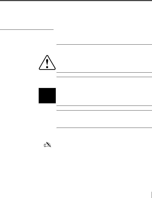
The HN router, as shown in Figure 1 on page 2, is a standalone unit that provides an integrated broadband LAN solution to platforms running IP over Ethernet. The HN router provides two 10/100 LAN ports with one being used for local LAN connectivity and one being used for WAN connectivity. The Ethernet LAN port can be connected via a straight-through or
Chapter 1 • Introduction |
1 |
1037753-0001 Revision A |
crossover Cat-5 cable to a single computer or to an Ethernet hub/switch port. It is completely self-contained requiring no external PC to host any functions or software. The software is automatically updated from the Network Operations Center. It also has an an internal modem (with telephone jack) to support the Virtual Private Network Automatic Dial Backup (VADB) feature.
|
|
|
Figure 1: HN router |
|
|
|
|
Router specifications |
Table 1 lists the specifications for the HN router. |
||
|
|
Table 1: Specifications for the HN router |
|
|
|
|
|
|
Weight |
2.4 lb (1.089 kg) |
|
|
|
|
|
|
Width |
1.7 inch (4.32 cm) |
|
|
|
4.5 inch (11.43 cm) with pedestal base |
|
|
|
|
|
|
Height |
9.5 inch (24.13 cm) |
|
|
|
9.75 inch (24.77 cm) with pedestal base |
|
|
|
|
|
|
Depth |
10.5 inch (26.67 cm) |
|
|
|
|
|
2 |
Chapter 1 • Introduction |
1037753-0001 Revision A |

|
Table 1: Specifications for the HN router |
|
|
Safe operating |
5 to 40°C (Above 5000 ft altitude, reduce maximum temperature by 1°C per |
temperature range |
1000 ft) |
|
|
Safe operating |
5% to 95% non-condensing |
humidity range |
|
|
|
Safe altitude |
10,000 ft |
|
|
Cooling method |
Convection |
|
|
Main processor |
300 MHz |
|
|
Main memory |
64 Mbyte |
|
|
Flash memory |
16 Mbyte |
|
|
Protocol support |
TCP/IP (Transmission Control Protocol/Internet Protocol) protocol suite |
|
|
Interfaces/ports |
• Two Ethernet ports supporting 10BaseT or 100BaseT operation, RJ45-switched |
|
• Telephone line port |
|
• Serial port, DTE/DCE RS-232, which supports the following protocols: |
|
– VISA (Veriphone 3200 and 3300) (the asynchronous protocol of Vanguard |
|
International Service Association credit card) |
|
– X.25 International Telecommunication Union-Telecommunication |
|
Standardization Sector (ITU-T) protocol standard for WAN communications |
|
– XPAD (X.25 Packet Assembler/Disassembler) |
|
– SDLC (Synchronous Data Link Control) |
|
– LLC (Logical Link Control) |
|
|
Power supplies and |
See Table 2 on page 11. |
power requirements |
|
|
|
Commissioning
Associated transport devices
Commissioning is the process of registering an HN router for service. During the commissioning process you may use auto selection or manual entry of parameters.
•Auto Selection - Allows you to choose the Network Access Provider (NAP) from a predetermined list of providers. Many of the commissioning parameters are automatically configured for the provider chosen.
•Manual Entry - This mode requires you to enter all parameters manually.
Installation and commissioning of the HN router requires configuring/commissioning tasks for the transport device. This version of the Installation Guide provides information on the following:
•ADTRAN Total Access 600R as described in Appendix E –
ADTRAN Total Access 600R, on page 99.
•Siemens Model 4100/4101 as described in Appendix F –
Siemens 4100/4101 DSL Modem, on page 117.
Chapter 1 • Introduction |
3 |
1037753-0001 Revision A |

Installation and commissioning steps
Contact information
The installation and commissioning of the HN router is a multi-step process involving two pieces of equipment—the HN router and the associated transport device. The workflow and chapter reference numbers for the process steps follow.
1.Preparing, installing, and commissioning the transport device
a.ADTRAN Total Access 600R
–Installing the ADTRAN 600R on page 100
–Connecting the ADTRAN on page 106
–Configuring the ADTRAN on page 107
–Confirming connectivity on page 115
b.Siemens 4100/4101 DSL Modem
–Installation overview on page 118
–Installing the modem on page 119
2.Preparing the router for installation Chapter 2 on page 5
3.Assembling the HN router Chapter 3 on page 9
4.Connecting the router to the transport device Chapter 4 on page 15
5.Commissioning the HN router Chapter 5 on page 19
6.Verifying the installation, commissioning, and connections Chapter 6 on page 37
If you experience installation problems with the HN Router, first try the Diagnostic Utilities on page 51.
For warranty or repair support, the contact information varies depending on the location. If the customer needs service, warranty or repair support, they should contact their customer service representative in accordance with their service agreement.
4 |
Chapter 1 • Introduction |
1037753-0001 Revision A |

Chapter 2
Preparing the HN router for installation
Items required for installation
This chapter discusses preparations you must make prior to installing the HN router and information you should know before beginning the installation.
Note: Install your trasport device before installing the HN router. The appendices listed below give the installation instructions for the trasport devices.
•Appendix E – ADTRAN Total Access 600R, on page 99
•Appendix F – Siemens 4100/4101 DSL Modem, on page 117
This chapter discusses the following tasks:
•Items required for installation on page 5
•Confirming installer PC and site requirements on page 6
•Customer site requirements on page 7
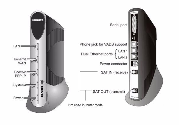
The HN router and the transport device shipping cartons contain the equipment necessary for installation. Before beginning the installation make sure you have all of the items shown in Figure 2 on page 6 and any other materials you may need.
Note: Customers who purchased their system from a Hughes retail channel receive an order confirmation e-mail.
Note: If the site has a DC power source, it will require a DC/DC power supply. See Table 2 on page 11. You must provide the wire required to assemble the DC input power cable.
Chapter 2 • Preparing the HN router for installation |
5 |
1037753-0001 Revision A |
Items required for Ensure the HN router shipping carton contains the items shown in installation Figure 2.
Cat-5 Ethernet cable |
|
|
Wall unit |
|
|
|
|
Warranty |
or |
|
|
In-line |
|
Warranty |
|
|
|
Pedestal base |
|
|
Power supply |
|
|
Wall unit or in-line unit |
Remote |
|
|
|
|
|
terminal |
|
Items provided in the remote terminal shipping carton |
|
|
|
Installation |
|
|
specification |
|
|
or work |
order |
|
|
|
terr.cfg file (if you are |
Installation specification |
|
instructed to upload it) |
or work order |
|
Items provided by the installer
G-29716 C 05/19/08
Figure 2: HN router components
Confirming installer PC and site requirements
You must confirm that your PC (the installer laptop) and the customer’s computer meet specific requirements before you install the HN router or the transport device. The installer laptop PC must meet the following requirements:
•Ethernet enabled network interface card (NIC) and Ethernet cable.
•Windows Vista, Windows XP, or Windows 2000 operating system with DHCP configured to automatically obtain IP addresses. See Appendix A – Configuring a computer to support DHCP, on page 69.
6 |
Chapter 2 • Preparing the HN router for installation |
1037753-0001 Revision A |
Customer site requirements
•Internet Explorer 6.0 or later with proxy settings disabled. See Appendix C – Disabling a Web browser’s proxy connection, on page 89.
•The latest version of the terr.cfg file if you are instructed to install it.
•All existing firewall software must be disabled.
The HN router can be used with any device that supports IP and has a 10/100 BaseT Ethernet port. Typically, the router is connected to a customer's computer. To run software that may be installed to support the router, the customer’s computer must meet the following requirements:
•Operating system
–PC: Windows Vista, Windows XP, Windows 2000
–MAC: 10.1 and higher
•Processor
–Vista PC: 800 Mhz or faster
–All other PCs: Pentium II 333 Mhz or faster
–MAC: 300 Mhz or faster
•Memory
–Vista PC: 512MB or 1 GB RAM depending on version
–All other PCs: 128MB RAM
–MAC: 128MB
•Free hard drive space
–PC: 100MB
–MAC: 150MB
•A functioning 10/100 BaseT Ethernet interface installed on at least one computer.
•The customer must provide a power strip or surge protector (recommended). If one of these is not present, use a wall outlet or other power source.
•The customer must have a WAN transport, for example DSL, available at their site that is ready for connection to and compatible with the modem that is to be attached to the HN router.
Note: Confirm that the installer laptop PC is configured to support Dynamic Host Control Protocol (DHCP) prior to beginning the installation. See Appendix A – Configuring a computer to support DHCP on page 69.
Chapter 2 • Preparing the HN router for installation |
7 |
1037753-0001 Revision A |

 CAUTION
Do not connect the power supply to the router, or connect the power supply to a power source until you are instructed to do so.
CAUTION
•Do not block any ventilation openings. Do not install near heat sources such as radiators, heat registers, ovens, stoves, or other apparatus (including amplifiers) that produce heat.
•Recommended ventilation space around the top and sides of the router assembly is approximately 6 inches. Ventilation is necessary to avoid overheating.
8 |
Chapter 2 • Preparing the HN router for installation |
1037753-0001 Revision A |

Chapter 3
Assembling and connecting the HN router hardware
This chapter explains how to assemble and make the connections to the HN router. It covers the following topics:
•Using the pedestal base on page 9
•Selecting the router location on page 11
•Connecting the power supply on page 11
Note: Refer to the following appendices for assembly directions for transport devices:
•Appendix E – ADTRAN Total Access 600R, on page 99
•Appendix F – Siemens 4100/4101 DSL Modem, on page 117
The router and the transport device must be fully assembled to make all the hardware connections and continue with the commissioning process.
Note: The HN router has two LAN ports (one for connecting to customer devices and the other for connecting to the associated modems), a serial port for connecting a serial device, and a phone line connector to support VADB. To install the HN7700S for VADB, see Chapter 8 – Configuring the HN router for VADB backup.
Using the pedestal base The HN router can be oriented in two ways: in a vertical position with the pedestal base or in a horizontal position without the
pedestal base when mounted in a ventilated rack.
The pedestal base ensures that the HN router receives proper ventilation. Use it to mount the HN router in a vertical position.
Chapter 3 • Assembling and connecting the HN router hardware |
9 |
1037753-0001 Revision A |
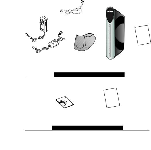
Attaching the base To attach the base to the router:
1. Position the router and pedestal base Figure 3.
Figure 3: Attaching the router to the pedestal base
2.Starting with the router bottom about ½ inch from the bottom of the pedestal base, slide the router into the base until the router locks into position.
Removing the base If you need to remove the router from the pedestal base:
1.Pull the release tab on the bottom of the base down. (See Figure 3.)
2.Slide the base away from the router.
10 |
Chapter 3 • Assembling and connecting the HN router hardware |
1037753-0001 Revision A |

Selecting the router location
Select a location for the router that will accommodate all required cable connections, including the power source. Place the router in the desired location.
CAUTION
•Do not block any ventilation openings. Do not place the router near heat sources such as radiators, heat registers, ovens, stoves, or other apparatus (including amplifiers) that produce heat.
•Leave 6 inches of space around the top and sides of the router to ensure ventilation and prevent overheating.
Connecting the power supply
Begin installation of the router by connecting the correct power supply. Use the power supply shipped with the router. Refer to Table 2 and Figures 4 and 5 to ensure you have the correct power supply type (AC/DC or DC/DC) for the unit.
CAUTION
•Always use the power supply provided with the system. The HN router’s performance may suffer if the wrong power supply is used.
•If the HN router is installed outside the United States or Canada, observe the power standards and requirements of the country where it is installed.
Table 2: Available power supplies for the HN router
Application |
Power |
Part number |
Electrical requirements |
Power cord |
|
supply type |
|||||
|
|
|
|
||
|
|
|
|
|
|
HN router |
AC/DC (64 W) |
1500089-0001 |
Input line voltage: |
Detachable, for |
|
|
|
|
100 – 240 V, 2 A max. |
110 VAC outlet type |
|
|
|
|
Input line frequency: |
|
|
|
|
|
50 – 60 Hz AC |
|
|
|
|
|
Rated power consumption: |
|
|
|
|
|
64 W |
|
|
|
|
|
|
|
|
|
DC/DC |
1033554-0001 |
Input line voltage: |
Detachable power |
|
|
|
|
12.7 – 25 V, 10 A max. |
input cables and |
|
|
|
|
Rated power consumption: |
connector |
|
|
|
|
64 W |
|
|
|
|
|
|
|
Chapter 3 • Assembling and connecting the HN router hardware |
11 |
1037753-0001 Revision A |
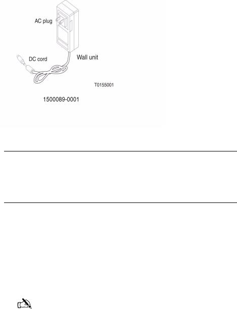
Connecting an AC/DC power Figure 4 shows the AC/DC power supply that is used with the HN supply router.
Figure 4: AC/DC power supply
CAUTION
The following apply if you use an AC/DC power supply:
•The input must be 110/240-VAC.
•A surge protector is recommended, whether you use an in-line power supply or wall unit.
In-line units The following instructions apply to AC/DC power supply with part number 1500089-0001. Refer to Figures 4 and 5. Connect the power supply as follows:
1.Connect the AC power cord to the power supply.
2.Connect the DC power cord to the DC IN port on the router, as shown in Figure 5 on page 13.
3.For an AC/DC power supply, make sure a suitable surge protector is available for the router.
Note: Protect the router with a suitable surge protector. Power surges are a common cause of failure for electronic devices.
Do not connect the AC power cord to the surge protector at this time. Wait until you are ready to observe the router’s LEDs upon power-up.
12 |
Chapter 3 • Assembling and connecting the HN router hardware |
1037753-0001 Revision A |
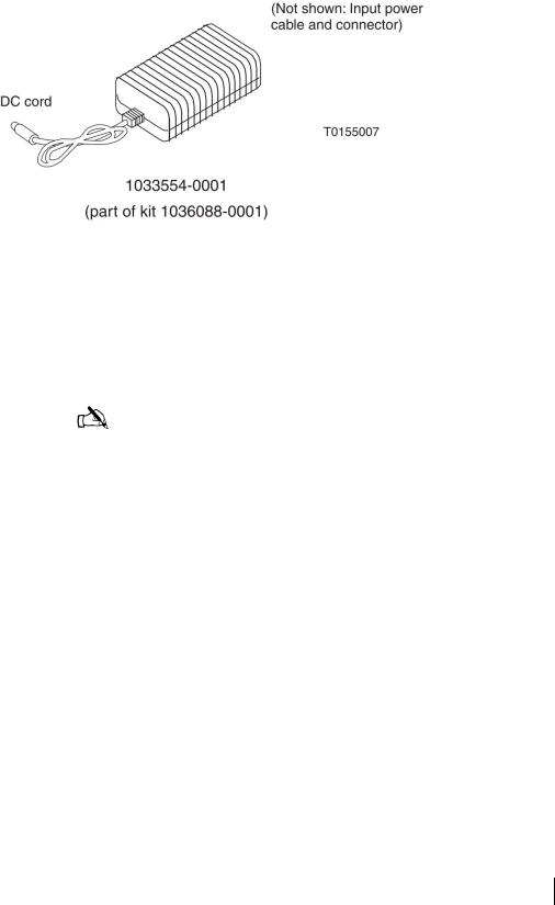
Connecting a DC/DC power Figure 5 shows the DC/DC power supply used with the HN supply router.
Figure 5: DC/DC power supply
Connect the DC/DC power supply as follows:
1.Connect the DC power cord to the DC IN port on the HN router.
2.Assemble the input power cable according to the wiring diagram included in the cable kit.
Note: The input cable kit is included in the power supply kit. The cable kit contains an input power connector, connector pins, and a wiring diagram; it does not include wire.
Connect the input power cable to the DC power source, but do not connect the input power connector to the power supply at this time.
Chapter 3 • Assembling and connecting the HN router hardware |
13 |
1037753-0001 Revision A |
14 |
Chapter 3 • Assembling and connecting the HN router hardware |
1037753-0001 Revision A |

Chapter 4
Connecting the HN router to a transport device
Connecting the cables to a modem transport device
This chapter explains how to connect the HN router to a transport device. It covers the following topics.
•Connecting the cables to a modem transport device on page 15
•Connecting the cables to a T-1 transport device on page 16
•Powering up and observing the router LEDs on page 16
To connect the modem transport device:
1.Connect the installer PC to LAN 1 with an Ethernet cable.
2.Connect the modem to LAN 2 of the router with an Ethernet cable.
3.Make sure that neither the router nor the customer’s computer are connected to an Ethernet router or switch.
4.Connect the power cables.
Note: Do not connect any devices to the HN router at this time. Serial and Ethernet devices may only be connected to the remote terminal after it is installed and commissioned.
Chapter 4 • Connecting the HN router to a transport device |
15 |
1037753-0001 Revision A |
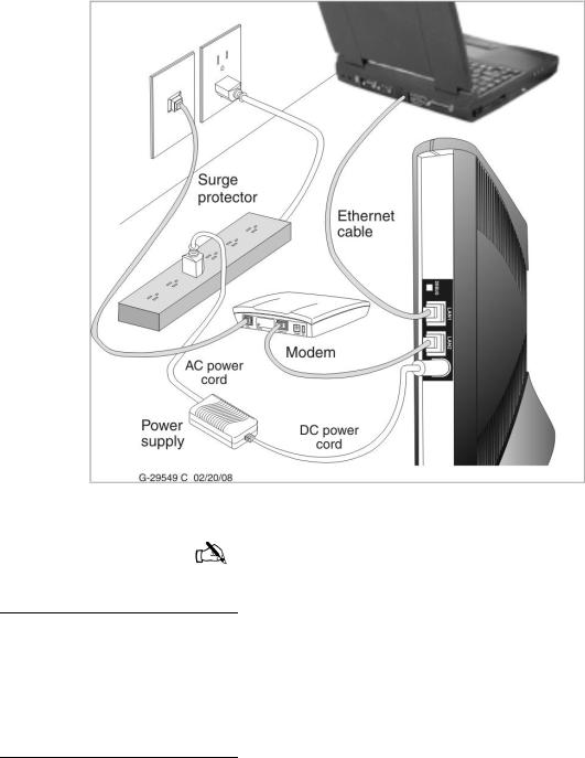
Figure 6 is a sample illustration of the connections using a modem transport device.
Figure 6: Connecting the cables
Note: Ensure the modem has been configured properly prior to connecting the cables.
Connecting the cables to a T-1 transport device
To connect the T-1 transport:
1.Connect the installer PC to LAN 1 with an Ethernet cable.
2.Use an Ethernet cable connected to the T-1’s 10/100 Base T port to LAN 2 of the HN router.
3.Connect the power cables.
Powering up and observing the router LEDs
Power up the remote terminal and watch the LEDs for normal operation, as follows.
16 |
Chapter 4 • Connecting the HN router to a transport device |
1037753-0001 Revision A |
Loading...