

Owner’s Manual
This manual contains important safety, assembly,
operation and maintenance information.
Please read and fully understand this manual before
operation.
Save this manual for future reference.
HGM-G-9 20 EN-AU 091515 m0301
Copyright Huffy Corporation 2015
Date Code Label
Here
EN
AU

2
Your Green Machine
• Owner’s Model Identication Record .....................................................3
• Warning and Safety Information ...........................................................4-5
• Assembly Notes - Tools Needed............................................................6
• Operating Your Green Machine ............................................................7-9
• Coaster Brake ......................................................................................9
Model Assembly
• Parts Assembly List ............................................................................10-11
• Assemble Front Frame to Rear Frame .................................................12
• Steering Arms .......................................................................................13
• Assemble Steering Linkage ................................................................14-15
• Assemble Rear Steering Axle .............................................................16-17
• Assemble Rear Wheels ........................................................................18
• Installing Seat .......................................................................................19
• Installing Pedals ...................................................................................20
Maintenance and Service
• Repair and Service ...............................................................................21
• Torque Chart .........................................................................................21
• Tires .....................................................................................................22
• Tire/Tube Replacement ........................................................................23
• Lubrication and Lubrication Table .........................................................24
• Inspection of the Bearings ....................................................................25
Warranty
• Corporation Limited Warranty .............................................................26-27
Contents

3
Green Machine
Owner’s Model Identication Record
NOTE: This information is only available with model itself. It is not available from
Huffy.
Model number is on the packaging and instruction manual.
Write the model number below to keep it for future reference.
If the model is stolen, give this number and a description of the model to the police.
This will help them nd the model.
Model Number:
Purchase Date:
Model Name:

4
Warnings and Safety
Warning and Safety Information
PLEASE READ AND FULLY UNDERSTAND THIS OWNERS MANUAL BEFORE
OPERATING THE PRODUCT
This symbol is important. See the word “CAUTION” or “WARNING” which fol-
lows it.
The word “CAUTION” is before mechanical instructions. If you do not obey these
instructions, mechanical damage or failure of a part of the product can occur.
The word “WARNING” is before personal safety instructions. If you do not obey these
instructions, injury to the rider or to others can occur.
All wheeled vehicles will provide safe, enjoyable transportation and recreation when
used and maintained properly. Like bicycling, skateboarding, and in-line skating, riding
can be dangerous even under the best of circumstances. We do not want you to get
hurt. Please follow all safety rules and operating instructions.
This toy should be used with caution since skill is required to avoid falls or collisions
causing injury to the user or third parties.
WARNING - TO AVOID SERIOUS INJURY:
• CHOKING HAZARD. Small parts. Not for children under 3 years.
• Adult assembly is required.
• Continuous adult supervision is required.
• The brake may be hot after continuous use. Do not touch after braking.
• Ensure rider can reach the pedals through full range of motion.
• Always wear a CPSC approved helmet while riding, with the chinstrap securely
fastened.
• Always wear shoes when riding.
• Ride on smooth paved surfaces. Do not ride on streets or roadways.
• Always comply with local laws and regulations.
• Never use near motor vehicles.
• Do not ride on hills, steeply sloped areas, on or near steps, near swimming pools,
or in alleys.
• Do not ride the product at dusk, at night or at times of limited visibility.
• Do not ride off road, on grass or wet surfaces.
• Do not ride the product over curbs or bumps that can damage the steering mechanism.
• Do not wear headphones or anything else that would impair your ability to hear or
see.
• Do not jump or ramp product.
• Do not tow the product.
continued >>

5
Warnings and Safety
Warning and Safety Information - continued
• Do not pull any objects with the product.
• Do not push the product.
• Never ride with more than one person. Maximum weight is 180 lbs (82Kg).
• Excessive weight may cause a hazardous or unstable condition.
• Understand all operating procedures before riding.
• Do not add a motor to the product.
• Do not modify the product.
• Before each ride check all screws, fasteners and brakes; re-tighten any that are
loose. Replace any fasteners that are damaged.
• Handlebar hand grip or tube end plugs should be replaced if damaged as bare
tubes have been known to cause injury. All products with capped handlebar ends
should be checked regularly to ensure that adequate protection for the ends of the
handlebars are in place.
• Replacement forks must have the same rake and tube inner diameter as the original product.
• Know your limits. Be familiar with your abilities. Use common sense.
• Replace worn or broken parts immediately.
• If anything does not operate properly, discontinue use.
IF YOU HAVE ANY QUESTIONS REGARDING THE OPERATION OF THIS
PRODUCT, PLEASE REFER TO THIS OWNERS MANUAL OR CALL
CONSUMER SERVICE
ASSEMBLY WARNINGS:
Wheels, Tire & Axle:
• The rear axle nuts must be securely
tightened to ensure rear wheels do not
come loose from the axle.
• All hardware must be sufciently tightened to ensure it does not come loose.
• Recommended tube/tire ination pressure is on the tire sidewall.
Pivot Bolt:
• Pivot bolt must be correctly and securely installed to ensure it does not
come loose.
Steering Function:
• Ensure the Steering Levers move
freely, front to back and all attaching
hardware is securely tightened.
Seat:
• Secure the seat adjustment bolts each
time the seat is moved.
Coaster Brake:
• Ensure seat is adjusted so rider can
easily reach the front wheel coaster
brake.
6
Assembly Notes
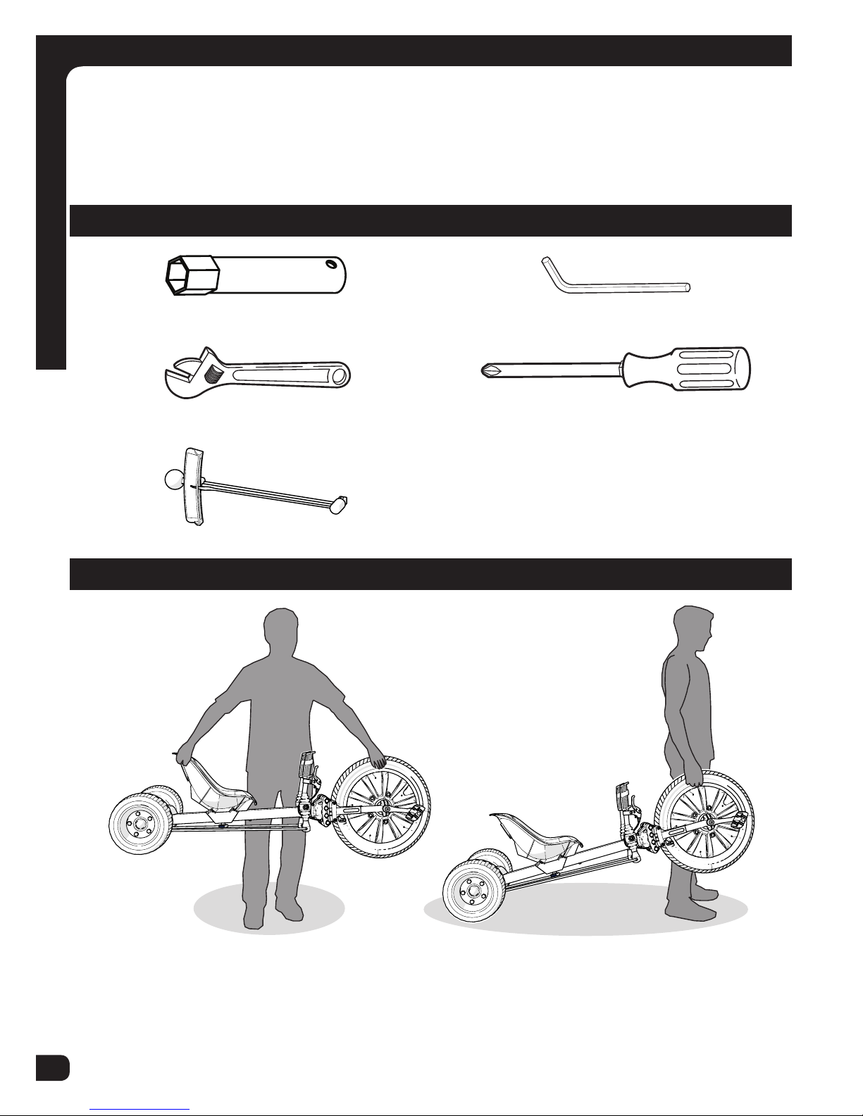
Assembly Notes
Required Tools
Suggested Handling Methods:
13mm socket (supplied) Metric Allen Wrench (supplied)
Adjustable Wrench Phillips Screwdriver
Torque Wrench (recommended)
The instructions in this manual refer to the right and left side of the product, these
are dened from the rider position. Do not discard any parts until the unit is completely assembled.
NOTE: Check Front Tire Pressure before rst ride!
7
Steering your Green Machine
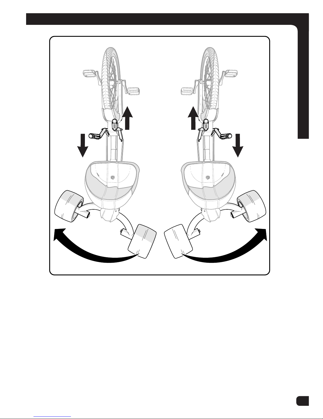
Operation
Steering Function:
• Pulling back on the left lever, and pushing forward on the right lever will turn the
product towards the left.
• Pulling back on the right lever, and pushing forward on the left lever will turn the
product towards the right.
• Steering this product takes some practice. Ensure the rider can properly steer the
product. Practice in an open area.
8
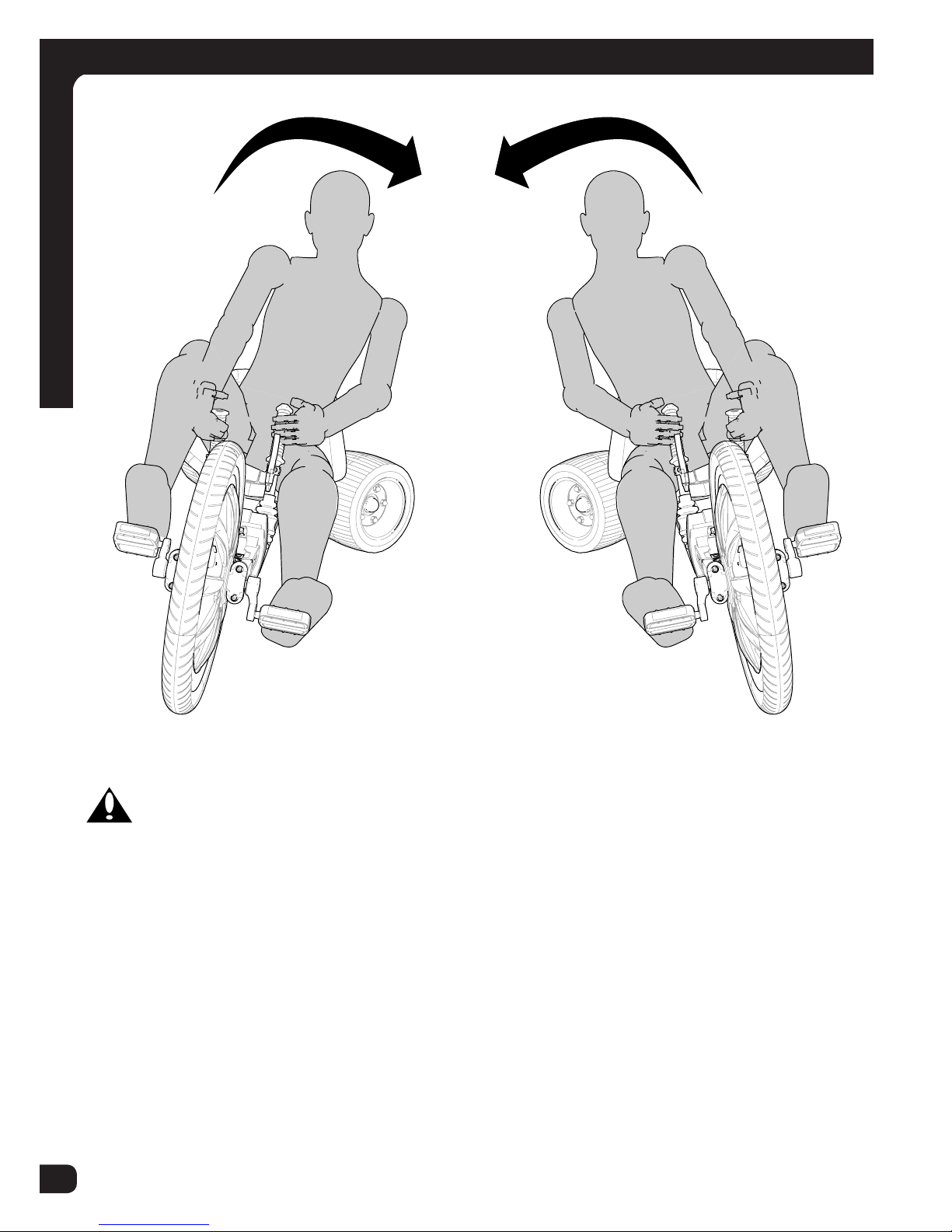
Operation
WARNING: Failure to lean in the direction of the turn as shown can result in
the unit rolling over.
Lean INTO a LEFT T urn
Lean INTO a RIGHT T urn
Leaning into a Turn
9
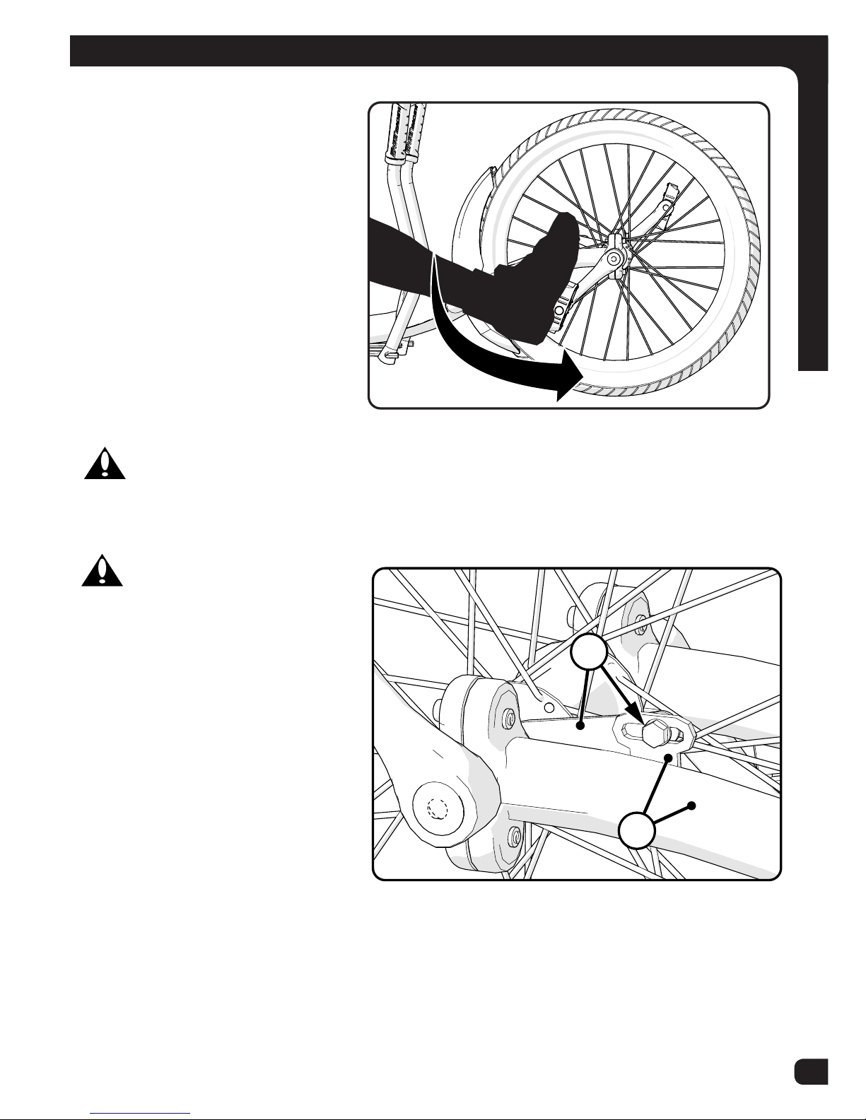
Coaster Brakes
These models are equipped with
a ‘coaster’ brake that is operated
by rotating the crank backwards.
Operation:
Operate the coaster brake as
follows:
• Push the pedal down and
forward as shown.
• As you push the pedals with
increasing force, the braking
action of the coaster brake
increases.
WARNING: Adjust Seat so that rider can fully use Coaster Brake safely.
WARNING: If you do not
obey the following instructions,
injury to the rider or to others can
occur :
• When you ride the product
the rst time, test the coaster
brake and practice using it at
a low speed in a large level
area that is free of obstructions.
• Every time the product is
ridden, make sure the Bolt on
the Brake Arm (A) is securely
attached to the Fork Mount
(B). The coaster brake will
not work correctly if the brake arm is loose or is not attached securely to the Fork
Mount.
• Removal of Brake Arm Bolt (A) will result in brakes NOT working.
A
B
Operation
Forward to Pedal, Backwards to Stop

10
Parts View
519
18
17
16
15
14
21
20
11
23
23
1
2
22
3
4
6
9
24
10
12
7 8
13
13
19
18
Parts Assembly View

11
Parts List
Parts Assembly List
No. Description No. Description
1 Forward Frame/Fork 15 Large Axle Bolt Washer (x2)
2 Rear Frame 16 Frame Bushings (x4)
3 Axle Frame 17 Wheel Bushings (x4)
4 Crank Assembly 18 Small Axle Washer (with Axle Bolt x2)
(with Axle Rod x 4)
5 Pedals (left / right) 19 Axle Nut (with Axle Bolt x2)
(with Axle Rod x4)
6 Tire 20 Rear Wheel (x2)
7 Tube 21 Rear Fairing / hardware
8 Wheel Assembly 22 Steering Fairing
9 Steer Levers (left / right) 23 Seat Adjustment Knob and Hardware
10 Grips (x2) 24 Frame Screws (x2)
11 Steering Links (x2)
12 Seat
13 Pivot Bolt Hardware
14 Axle Bolt or Rod (x2)

12
Assembly
Assemble Front Frame to Rear Frame
NOTE: See Torque Chart for recommended torques.
B
A
C
EF
D
1 2
STEPS:
NOTE: Mounting Screws (A) may be pre installed at the factory.
1. Begin by loosening Screws (A) slightly.
2. Make sure rear section of Frame (B) is right side UP: Rear Stop (C) will be on the
top of the Frame.
3. Insert Rear Frame Tubes fully and evenly into front Frame Tubes (D).
WARNING: Ensure the Lock Button (E) on the Rear Frame section is fully
engaged with the Locking Hole Stop (F) in the end of the front Frame Tube. Failure to
fully engage the lock button can result in personal injury.
4. Tighten Screws (A) evenly and securely.

13
Assembly
Steering Arms
B
A
NOTE: The Steering Arms (A) are pre-assembled at the factory. Periodically check
tightness of Bolts/Screws (B). See Torque Chart for recommended torques.

14
Assembly
Attaching Steering Linkage - Front
FORWARD
B
A
E
D
C
R
L
STEP 1:
1. Insert end of Right Steering Rod (A) with SHORTER End (B) into Steering Rod
Handle Ends (C) as shown on right side of unit.
2. Make sure Rods are on the OUTSIDE (view D) of the Steering Rods as shown
and back of Rods are pointing UP (E).
3. Repeat on left side.
Proceed to next step >>

15
Assembly
Attaching Steering Linkage - Rear
STEP 2:
1. Rotate Rear Axle (A) UP 90°.
2. Move Frame (B) slightly to the side.
3. Insert both Steering Rods (C) into Pivot Bracket holes (D) as shown.
A
C
D
D
C
1
2
B
Proceed to next step >>

16
Assemble Rear Steering Axle
A
E
D
C
B
1
2
STEP 3:
1. Rotate Rear Axle back to horizontal, while moving Frame (A) into place between
Pivot Bracket holes (B).
2. Swing the Frame (A) into the Pivot Bracket (B) so the mounting holes line up.
3. Install Pivot Bolt (C) though Pivot Bracket and Rear Frame pivot end.
4. Install Washer (D) and Locknut (E) onto Pivot Bolt.
5. Tighten Locknut securely. See Torque Chart for recommended torque.
WARNING: Periodically check Pivot Bolt Nut for tightness. If the Pivot Bolt
comes lose, damage to the product or rider injury may occur.
Assembly

17
Installing Pivot Bolt Cover
STEPS:
NOTE: Screws (C) maybe pre-installed in Rear Axle Plate (B). Remove and set
aside.
1. Place Pivot Bolt Cover (A) over Rear Axle Plate (B) so that mounting holes line
up.
2. Install two Screws (C) through Cover and into Rear Axle Plate.
3. Install Screws securely. No not over tighten.
NOTE: Cover must be removed to check Pivot Bolt for tightness.
A
B
C
Assembly

18
Installing Rear Wheels
A
F
G
G
F
B
CD
2
1
E
D
Assembly
STEPS:
NOTE: Axle may be Bolt style or Threaded Rod style (D). Threaded Rod style will
have a Washer (F) and Lock Nut (G) on both ends. Bolt Style will have a larger
Washer (C) under the head of the Bolt.
1. Insert a Bushing (B) in both Wheel Axle Holes. Ensure Bushing is fully seated
in the wheel. (Bushings may be pre-installed)
2. Position Wheel (A) with inset graphic facing outwards.
3. If Threaded Axle Rod style (1): Place a Washer (F) and Lock Nut (G) on one
end of Axle Rod (D). Insert Axle Rod through Frame (E).
4. If Bolt style (2): Place larger Washer (C) onto Axle Bolt (D) and insert Axle Bolt
through Frame (E).
5. Place Wheel/Bushing assembly over end of Axle (D) making sure Bushings (B)
do not come loose.
6. Install Washer (F) and Lock Nut (G) onto Axle.
7. Tighten Lock Nut(s) securely. See Torque Chart for recommended torque.
8. Repeat steps for opposite side wheel.
WARNING:
• Ensure Axle Bolt Threads are fully through the Lock Nuts.
• Ensure Wheels spin freely and evenly and are not loose side to side.

19
Installing Seat
SEAT:
1. Place Seat (A) over Frame Seat Holes (B) (adjust Seat position for proper t).
2. Insert Washer (C) and Seat Bolt (D) through Seat as shown.
3. Attach Adjustment Knob (E) to Seat Bolt (D) from underneath.
4. Tighten Adjustment Knob securely. Do not over tighten. This can damage the
Seat.
NOTES:
• Seat styles may vary.
• Retain tools for later adjustment.
• See Torque Chart for recommended torques.
WARNING: Adjust Seat so that rider can fully use Coaster Brake safely.
A
B
B
C
D
D
E
E
Assembly

20
Assembly
Installing Pedals
R
L
1. Install the pedal marked “R” (Right) on
the right side. Tighten clockwise as
shown.
2. Install pedal marked “L” (Left) on the
left side. Tighten counterclockwise as
shown.
3. Make sure threads of each pedal are
fully into crank arm.
4. Tighten securely.
NOTE: See Torque Table for recommended torque.

21
Repair and Service
WARNING:
• Inspect the model frequently. Failure to inspect the model and to make repairs
or adjustments, as necessary, can result in injury to the rider or to others. Make
sure all parts are correctly assembled and adjusted as written in this manual and
any “Special Instructions”.
• Immediately replace any damaged, missing, or badly worn parts.
• Make sure all fasteners are correctly tightened as written in this manual and
any “Special Instructions”. Parts that are not tight enough can be lost or operate poorly. Over tightened parts can be damaged. Make sure any replacement
fasteners are the correct size and type.
NOTE: Have a bike service shop make any repairs or adjustments for which you do
not have the correct tools or if the instructions in this manual or any “Special Instruc-
tions” are not sufcient for you.
Maintenance
Torque Chart
Recommended Torque:
Use of a torque wrench is recommended. Recommended torque for each fastener is
listed below. In addition to tightening to the recommended torque, please ensure the
parts of the product are sufciently tightened by performing the functional tests (in
the component assembly sections of the owner’s manual) on each component as it is
tightened.
NOTE: Please check that all fasteners on the product are torqued according to the
table below:
Recommended Torque for clean, dry threads: How to Measure:
Fastener Size Torque (ft-lb / N•m)
Screw or bolt size is determined
by the width at the THREADS
as shown.
.157 in (4 mm) 3.1 ft-lbs (4.2 N•m)
.196 in (5 mm) 5 ft-lbs (6.8 N•m)
.236 in (6 mm) 7 ft-lb (9.5 N•m)
.275 in (7 mm) 12 ft-lbs (16.3 N•m)
.314 in (8 mm) 17 ft-lbs (23 N•m)
.393 in (10 mm) 33 ft-lbs (44.7 N•m)
Pedals 24 ft-lbs (30 N•m)

22
Maintenance
Tires
Maintenance:
• Frequently check the tire ination pressure because all tires lose air slowly over
time. For extended storage, keep the weight of the model off the tires.
• Do not use unregulated air hoses to inate the inner tubes. An unregulated hose
can suddenly over inate model tires and cause them to burst.
• Replace worn tires.
CAUTION: Do not ride or sit on the model if a tire is under inated. This can
damage the tire and inner tube.
Inating the Tires:
• Use a hand or a foot pump to inate the tires.
• Service station meter-regulated air hoses are also acceptable.
• The maximum ination pressure is shown on the tire sidewall.
• If two ination pressures are on the tire sidewall, use the higher pressure for on-
road riding and the lower pressure for off-road riding.
• The lower pressure will provide better tire traction and a more comfortable ride.
Before adding air to any tire, make sure the edge of the tire (the bead) is the same
distance from the rim, all around the rim, on both sides of the tire. If the tire does not
appear to be seated correctly, release air from the inner tube until you can push the
bead of the tire into the rim where necessary. Add air slowly and stop frequently to
check the tire seating and the pressure, until you reach the correct ination pressure.
Tire Pressure Table
Recommended Tire Pressure
(kilopascals):
Frequently check the tire ination
pressure because all tires lose air
slowly over time. For extended
storage, keep the weight of the product
off the tires.
Recommended tire pressure is marked
on the side of the tire. Conversion from
PSI to Kilopascals is shown here.
Tire Pressure: (PSI to Kpa Conversion)
PSI Kpa
20 140
30 210
40 275
50 345
60 415

23
Maintenance
Tire and Tube Replacement
STEP 1 - Remove Existing Tire and Tube:
1 2 3
A
Steps (start opposite Filler Valve):
1. Insert a Tire Lever under Tire Bead (A).
2. Hook end of Tire Lever on a spoke.
3. Insert second Tire Lever and slide along rim to remove tire bead.
4. Remove Inner Tube and Tire.
5. Inspect for cause of at and remove any foreign object from the tire if necessary.
1. Using your hands, start with one Bead (A) of Tire (B) and install it all the way
around Rim (C).
2. Insert a slightly inated Inner Tube (D) into
the Tire and make sure the Valve Stem (E) is
straight and aligned with the Rim Hole.
3. Work the second Tire Bead onto the Rim all
the way around. This will take a little more
effort than the rst Tire Bead did. Use Tire
Lever Tools if needed.
4. Make sure the Tube does not get pinched
between Rim and Tire.
5. Inate Tire just enough that it takes shape.
6. Double check that both Tire Beads are seated
properly and that the Valve Stem is pointing
straight out.
7. Fully inate tube to recommended pressure
listed on Tire side wall - do not over-inate.
8. Install Valve Cap.
STEP 2 - Installing New Tire and Tube:
D
A
B
C
E

24
Lubrication Table
What When How
Pedals every six months Put four drops of oil where the axles go into
the pedals.
Lubrication
WARNING:
• Do not over lubricate. If oil gets on the wheel rims or the brake shoes, it will
reduce brake performance and a longer distance to stop the model will be necessary. Injury to the rider or to others can occur.
• Keep all oil off the surfaces of the pedals where your feet rest.
• Using soap and hot water, wash all oil off the wheels, the pedals, and the tires.
• Rinse with clean water and dry completely before you ride the model.
• Using a light machine oil (20W), lubricate the model according to the following
table:
Maintenance

25
Inspection of the Bearings
Maintenance
Frequently check the bearings of the model. Lubricate or have a bicycle service shop
lubricate the bearings once a year or any time the front wheel does not spin freely
and easily.
Wheel Bearings
Lift the front wheel off the ground and slowly spin the wheel by hand. The bearings
are correctly adjusted if:
• The wheel spins freely and easily.
• There is no side-to-side movement at the wheel rim when you push it to the side
with light force.
Maintenance

26
Warranty
Limited Warranty
General:
• Part or model speci cations are subject to change without notice.
• This Limited Warranty is the only warranty for this product. There are no other
expressed or implied warranties.
• This Limited Warranty extends only to the original consumer and is not transferable
to anyone else.
• Warranty registration is not required.
• The only uses for this product are described in this manual.
What does this Limited Warranty cover?
This Limited Warranty covers all parts of the product except those indicated below as
not warranted.
What must you do to keep the Limited Warranty in effect?
This Limited Warranty is effective only if:
• Product is completely and correctly assembled.
• Product is used under normal conditions for its intended purpose (see the following
section for excluded activities).
• Product receives all necessary maintenance and adjustments.
• Product is used for general transportation and recreational use only.
What is not covered by this Limited Warranty?
This Limited Warranty does not cover normal wear and tear, normal maintenance
items, or any damage, failure, or loss that is caused by improper assembly, maintenance, adjustment, storage, or use of the Product.
This Limited Warranty will be void if the unit is ever:
• Used in any competitive sport
• Used for stunt riding, jumping, aerobatics or similar activity
• Modi ed in any way
• Modi ed with the addition of a motor
• Ridden by more than one person at a time
• Rented, sold, or given away
• Used in a manner contrary to the instructions and warnings in this Owner’s Manual
Huffy will not be liable for incidental or consequential loss or damage, due directly or
indirectly from use of this product. Some states do not allow the exclusion or limitation
of incidental or consequential damages, so the above limitation may not apply to you.

27
Warranty
Limited Warranty -continued
What rights do you have?
This warranty gives you speci c legal rights. You may also have other rights which
vary from state to state.
What will Huffy do?
Huffy will replace, without charge to you, the component found to be defective by Huffy.
CONTACTING CUSTOMER SERVICE:
How do you report a problem with this product or submit a warranty claim?
• Contact Consumer Service - See included list for Customer Contact information.
IN AUSTRALIA:
• Contact Customer Service for Australia or New Zealand. Warranty claims can
be submitted to Huffy c/o Hunter Products Pty., Ltd., Level 2, 424 Warrigal Road,
Moorabbin, Victoria 3189 Australia.
The following text is incorporated into this Limited Warranty if this product was purchased in Australia (but it is not incorporated if such product was purchased in New
Zealand):
• Our goods come with guarantees that cannot be excluded under the Australian
Consumer Law. You are entitled to a replacement or refund for a major failure and
for compensation for any other reasonably foreseeable loss or damage. You are
also entitled to have the goods repaired or replaced if the goods fail to be of acceptable quality and the failure does not amount to a major failure.
How long does this Limited Warranty Last?
• Warranty is from date of purchase.
• Frame and all components are warranted for six (6) months.
• Resin wheels are not warranted.

• Helmet should sit level on your head and low on your forehead
• Adjust the strap sliders below the ear on both sides.
• Buckle the chin strap. Adjust strap until it is snug.
• No more than two ngers should t between the strap and your chin.
• A proper tting helmet should be comfortable and not rock forward/back-
ward or side to side.
• Always read the user manual that comes with your helmet to make sure it
is tted and attached properly to the wearer’s head according to the tting
instructions described in the user manual.
Check www.Huffy.com for the current contact information
WARNING:
ALWAYS WEAR YOUR
HELMET WHEN RIDING
THIS PRODUCT!
 Loading...