

Page 1
1
01/04 P/N 211475
© COPYRIGHT 2000 by HUFFY SPORTS
Toll-Free Customer Service Number for U.S: 1-800-558-5234,
For Canada: 1-800-284-8339,
For Europe: 00 800 555 85234 (Sweden: 009 555 85234),
For Australia: 1-800-333 061
Internet Address: http://www.huffysports.com
HUFFY
REQUIRED TOOLS AND MATERIALS:
• Two People
• Wood Board (Scrap)
• Tape Measure
• Step Ladder 8 ft. (2.4 m)
• Tape
• Garden Hose or Sand 360 lb. (163 kg)
• Hammer
• Wrenches: (Two) 3/4”, (One) 1/2” (Two) 9/16”or
equivalent sockets, (One) 1/2” Deep well socket
with extension and socket wrench, 3/8 socket
• Support Table
• Phillips Head Screwdriver
Portable Basketball System
Owners Manual
Customer Service Center
• N53 W24700 South Corporate Circle • Sussex, WI 53089 • U.S.A.
READ AND UNDERSTAND
OPERATOR'S MANUAL
BEFORE USING THIS UNIT.
FAILURE TO FOLLOW
OPERATING INSTRUCTIONS
COULD RESULT IN INJURY
OR DAMAGE TO
PROPERTY.
WARNING!
HU
FFY
SPORTS
Page 2
2
P/N 211475 01/04
WARNING
FAILURE TO FOLLOW THESE WARNINGS MAY RESULT
IN SERIOUS INJURY AND/OR PROPERTY DAMAGE.
Owner must ensure that all players know and follow
these rules for safe operation of the system.
• DO NOT HANG on the rim or any part of the system
including backboard, suppor t braces or net.
• During play, especially when performing dunk type
activities, keep player's face away from the backboard, rim
and net. Serious injury could occur if teeth/face come in
contact with backboard, rim or net.
• Do not slide, climb, shake or play on base and/or pole.
• After assembly is complete, fill system completely with
water or sand and stake to the ground. Never leave system
in an upright position without filling base with weight, as
system may tip over causing injuries.
• When adjusting height or moving system, keep hands and
fingers away from moving parts.
• Do not allow children to move or adjust system.
• During play, do not wear jewelry (rings, watches, necklaces,
etc.). Objects may entangle in net.
• Surface beneath the base must be smooth and free of
gravel or other sharp objects. Punctures cause leakage and
could cause system to tip over.
• Keep organic material away from pole base. Grass, litter,
etc. could cause corrosion and/or deterioration.
• Check pole system for signs of corrosion (rust, pitting,
chipping) and repaint with exterior enamel paint. If rust has
penetrated through the steel anywhere, replace pole
immediately.
• Check system before each use for proper ballast, loose
hardware, excessive wear and signs corrosion and repair
before use.
•
Check system before each use for instability.
• Do not use system during windy and/or severe weather
conditions; system may tip over. Place system in the
storage position and/or in an area protected from the wind
and free from personal property and/or overhead wires.
• Never play on damaged equipment.
• See instruction manual for proper installation and
maintenance.
• When moving system, use caution to keep mechanism from
shifting.
• Keep pole top covered with cap at all times.
• Do not allow water in tank to freeze. During sub-freezing
weather add non-toxic antifreeze, sand or empty tank
completely and store. (Do not use salt.)
• Use extreme caution if placing system on sloped surface.
System may tip over more easily.
201241 2/99
In the U.S.:1-800-558-5234 and Canada: 1-800-284-8339
Page 3
01/04 P/N 211475
3
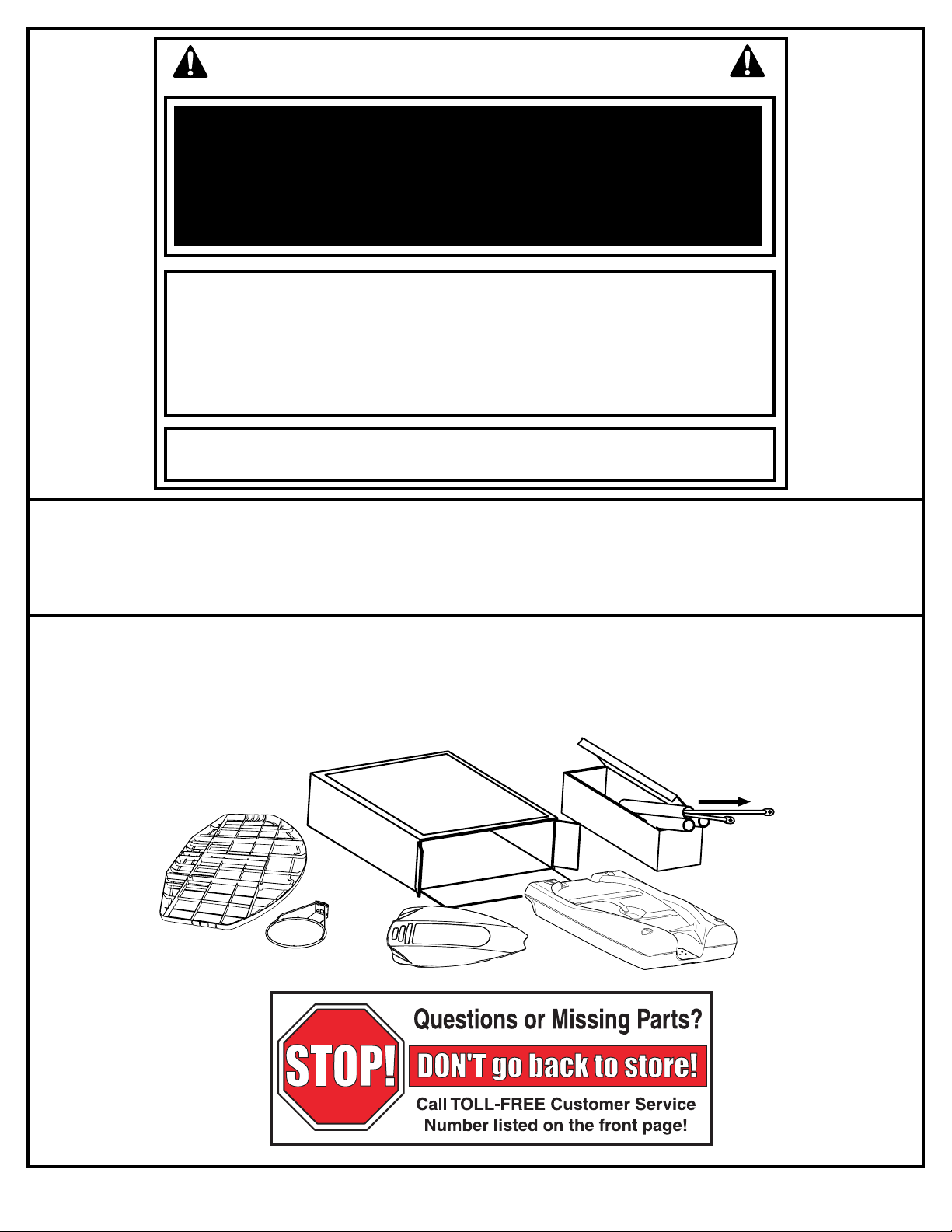
IMPORTANT!
Remove all contents from boxes.
Be sure to check inside pole sections;
hardware and additional parts are packed inside.
NOTICE TO ASSEMBLERS
ALL Huffy Sports basketball Systems, including those used for DISPLAYS, MUST be assembled
and ballasted with sand or water according to instructions. Failure to follow instructions could
result in SERIOUS INJURY. It is NOT acceptable to devise a makeshift weight system.
SAFETY INSTRUCTIONS
FAILURE TO FOLLOW THESE SAFETY INSTRUCTIONS MAY RESULT IN SERIOUS INJURY,
PROPERTY DAMAGE AND WILL VOID WARRANTY.
Owner must ensure that all players know and follow these rules for safe operation of the system.
To ensure safety, do not attempt to assemble this system without following the instructions carefully. Proper
and complete assembly, use and supervision is essential for proper operation and to reduce the risk of
accident or injury. A high probability of serious injury exists if this system is not installed, maintained, and
operated properly.
• If using a ladder during assembly, use extreme caution.
• Check base regularly for leakage. Slow leaks could cause the system to tip over
unexpectedly
• Seat the pole sections properly (if applicable). Failure to do so could allow the pole
sections to seperate during play and/or during transport of the system.
• Climate, corrosion or misuse could result in system failure.
• If technical assistance is required, contact Huffy Sports.
• Minimum operational height is 6’6” (1.98m) to the bottom of backboard.
Most injuries are caused by misuse and/or not following instructions.
Use caution when using this unit.
Page 4
4
P/N 211475 01/04
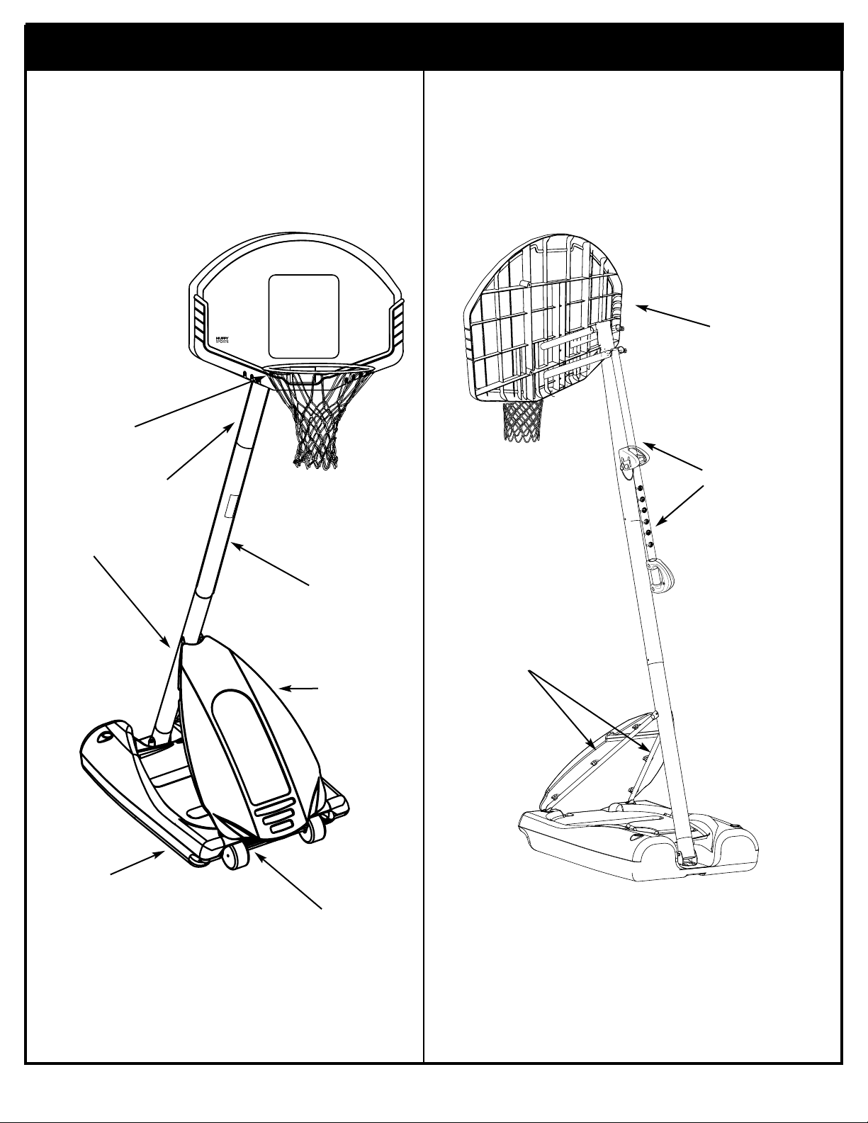
Get to know the basic parts of your basketball system.....
FRONT
TOP POLE
BACK
MIDDLE POLE
FRONT
COVER
RIM
BOTTOM
POLE
STRUTS
ELEVATOR
ASSEMBLY
BACKBOARD
BASE
WHEEL
CARRIAGE
ASSEMBLY
Page 5

01/04 P/N 211475
5
Item Qty Part No. Description
1 1 908026 Top Pole Section
2 1 908107 Middle Pole Section (with Label)
3 1 908015 Bottom Pole Section
4 1 900223 Wheel Bracket
5 1 206940 Axle
6 2 226403 Wheel
7 2 206938 Pushnut
8 1 206660 Base
9 6 203156 Hex Bolt, 5/16-18 x 1
10 18 203218 Flat Washer, 5/16
11 21* 203100 Hex-Flange Nut, 5/16-18
12 1 201581 Pole Bracket
13 2 202662 Hex Bolt, 5/16-18 x 4.5
14 2 203099 Locknut, 5/16-18
15 4 203223 Carriage Bolt, 5/16-18 x 1
16 2 906410 Tank Strut
17 1 200516 Bolt Cover
18 1 206990 Reinforcement Bracket
19 3 203038 Carriage Bolt, 5/16-18 x 2-3/4 Long
20 8 202862 Spacer, Plastic, 1.19" Long
21 7* 206340 Locknut, 1/2-13
22 2 203053 Carriage Bolt, 5/16-18 x 4 Long
23 1 204872 Label, Height Indicator
24 2 204858 Spacer, Plastic, Biscuit
25 1 207103 Pole Cap
26 1 204853 Lanyard, Black Coil
27 1 204850 Pin, Locking
28 1 204832 Bracket, Pole Mount
29 4 206360 Hex Bolt, 3/8-16 x 2.625
30 2 201129 Spacer, Metal
31 4 201124 Locknut, 3/8-16
32 2 900867 Plate, Triangle
33 2 904807 Elevator Tube, Upper - Short
34 2 900183 Elevator Tube, Lower - Long
35 2 204859 Cover, Pin Slide
36 1 203124 Tie Down Stake
37 2 203617 Base Plug
38 1 201965 Front Cover
39 6* 203257 Tie Straps
40 1 Rim
41 4 203309 Washer, Flat
42 1 201252 Label, Height Adj and Moving
43 2 204857 Spacer, Metal 1/2” O.D. x 1.44 Long
44 4 203232 Flat Washer, 3/8
45 2 900846 Bracket, Backboard Support
46 1 240017 Bolt, Hex, 1/4-20 x 2.25" Long
47 1 202605 Bolt, Hex, 1/2-13 x 4.25" Long
48 1 204837 Spring, Counter Balance
49 4 201682 Spacer, .530 I.D. x 1.875
50 6 202532 Bolt, Hex, 1/2-13 x 9.5"
51 1 904866 Height Adjustment Rod
52 1 204855 Handle, Left
53 1 204856 Handle, Right
54 2 203103 Carriage Bolt, 5/16-18 x 2 Long
55 1 204803 Screw, Phillips Head
56 1 204444 Rope
57 12 201219 Smart Clips, Net Holder
58 1 Net
59 4 203113 Bolt, Hex Flange, 5/16-18 x 2.5" Long
60 1 203493 Locknut, 1/4-20
* You may have extra parts with this model.
WARRANTY CARD:
Please remember to complete your product
registration form either on-line at:
www.huffysports.com/warrantycard or mail-in
the enclosed postcard.
Page 6
6
P/N 211475 01/04
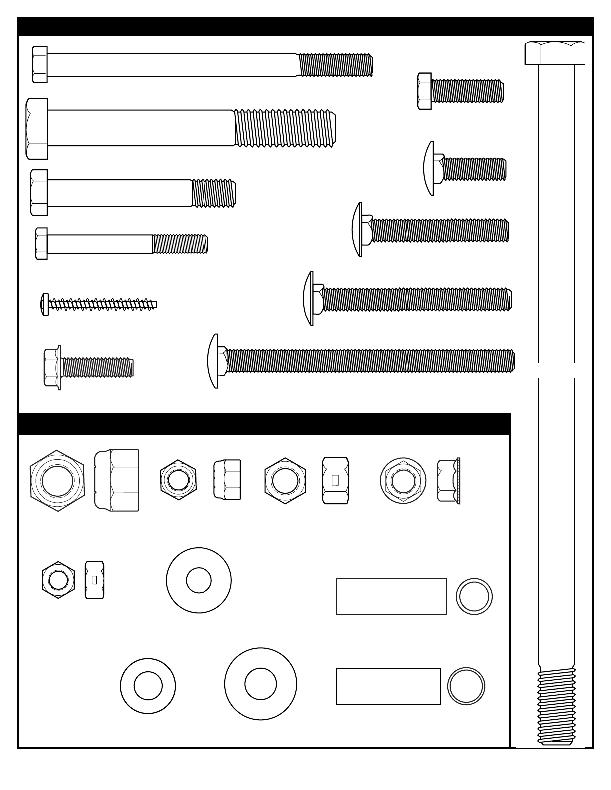
HARDWARE IDENTIFIER (BOLTS & SCREWS)
Item #14 (2)
Item #31 (4)
Item #55 (1)
Item #44 (4)
Item #11 (15)
Item #9 (6)
Item #50 (6)
Item #19 (3)
Item #10 (18)
Item #43 (2)
Item #21 (7)
Item #22 (2)
HARDWARE IDENTIFIER (NUTS, WASHERS & METAL SPACERS)
Item #54 (2)
Item #15 (4)
Item #30 (2)
Item #41 (4)
Item #59 (4)
Item #46 (1)
Item #29 (4)
Item #47 (1)
Item #13 (2)
Item #60 (1)
Page 7
01/04 P/N 211475
7
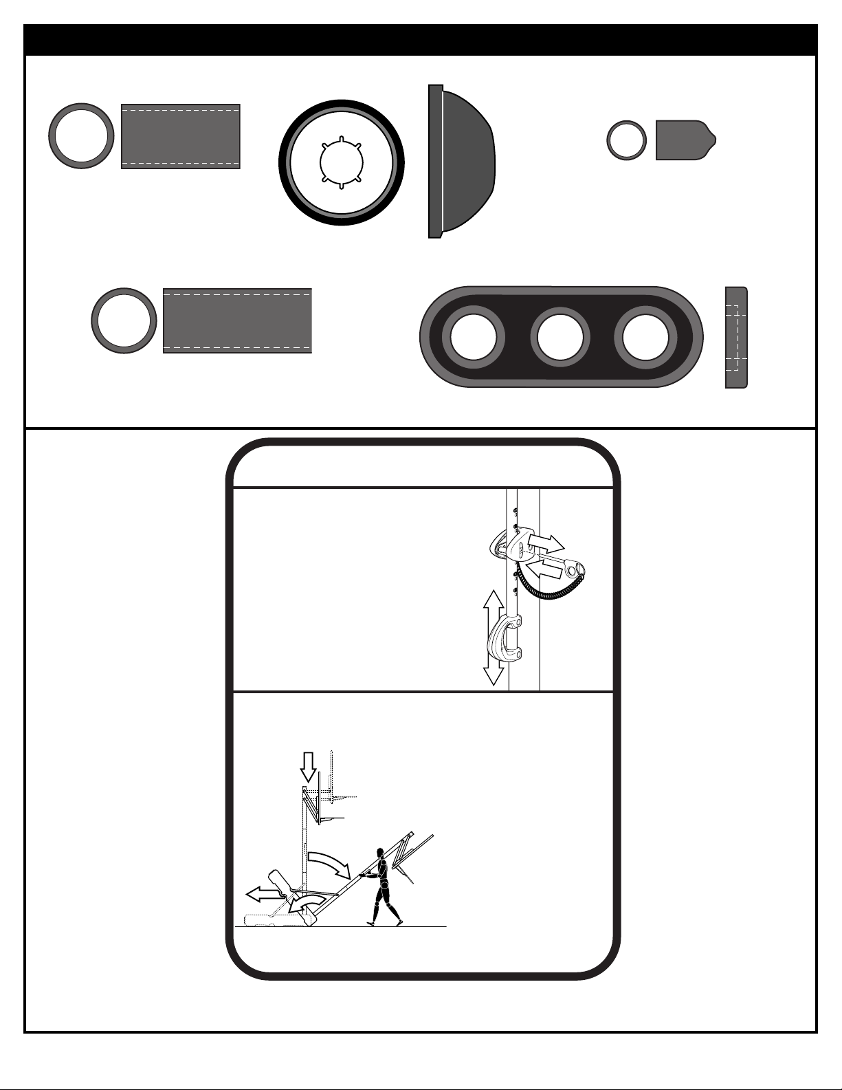
Item #20 (8)
Item #42 (1)
HARDWARE IDENTIFIER (PLASTIC SPACERS & CAPS)
Item #17 (1)
Item #49 (4)
Item #24 (2)
Item #7 (2)
HEIGHT ADJUSTMENT
TO ADJUST BACKBOARD:
1. While holding handle, remove pin.
2. Move elevator up or down to
desired height.
3. Replace pin full length to lock
system at desired height.
2
1
3
2
MOVING SYSTEM
1. Adjust basketball backboard
1
2
3
4
height to lowest position.
2. While holding pole, rotate
basketball system forward
until wheels engage with
ground.
3. Move basketball system to
desired location.
4. Carefully rotate basketball
system upright.
5. Reattach ground restraint and
check system for stability.
201252 2/99
Page 8
8
P/N 211475 01/04
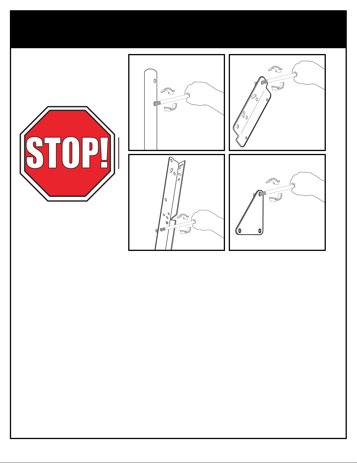
BEFORE YOU START!
To ensure optimal playability of backboard system, a close tolerance fit between the elevator
components and hardware is required. Test fit large bolts into large holes of elevator tubes,
backboard brackets and triangle plates. Carefully rock them in a circular motion to ream out
any excess paint from holes if necessary.
AVANT DE COMMENCER !
Pour garantir l'utilisation optimale du panneau, les composants du système élévateur et la visserie doivent être bien
ajustés (serrés). À titre d'essai, insérez les gros boulons dans les gros trous des tubes du système élévateur, des supports
du panneau et des plaques triangulaires. Basculez-les avec précaution en imprimant un mouvement circulaire pour
éliminer l'excédent de peinture, si nécessaire.
¡ANTES DE COMENZAR!
Para asegurar el óptimo rendimiento del sistema del respaldo en el juego, se requiere un ajuste de tolerancia estrecha
entre los componentes del elevador y el herraje. Pruebe el ajuste de los pernos grandes en los orificios grandes de los
tubos elevadores, soportes del respaldo y placas triangulares. Cuidadosamente muévalos en círculos para eliminar
cualquier exceso de pintura, si es necesario.
VORBEREITENDE MASSNAHMEN
Um sicherzustellen, dass das Korbwandsystem optimal für den Spielbetrieb geeignet ist, müssen die Komponenten der
Verlängerungsvorrichtung und die verschiedenen Befestigungsteile fest miteinander verschraubt werden. Große Schrauben
zur Probe in die großen Löcher der Verlängerungsrohre, Korbwandklammern und Dreiecksplatte stecken und diese
vorsichtig in einer Kreisbewegung hin- und herbewegen, um eventuelle Farbrückstände aus den Bohrungen zu entfernen.
Page 9
01/04 P/N 211475
9
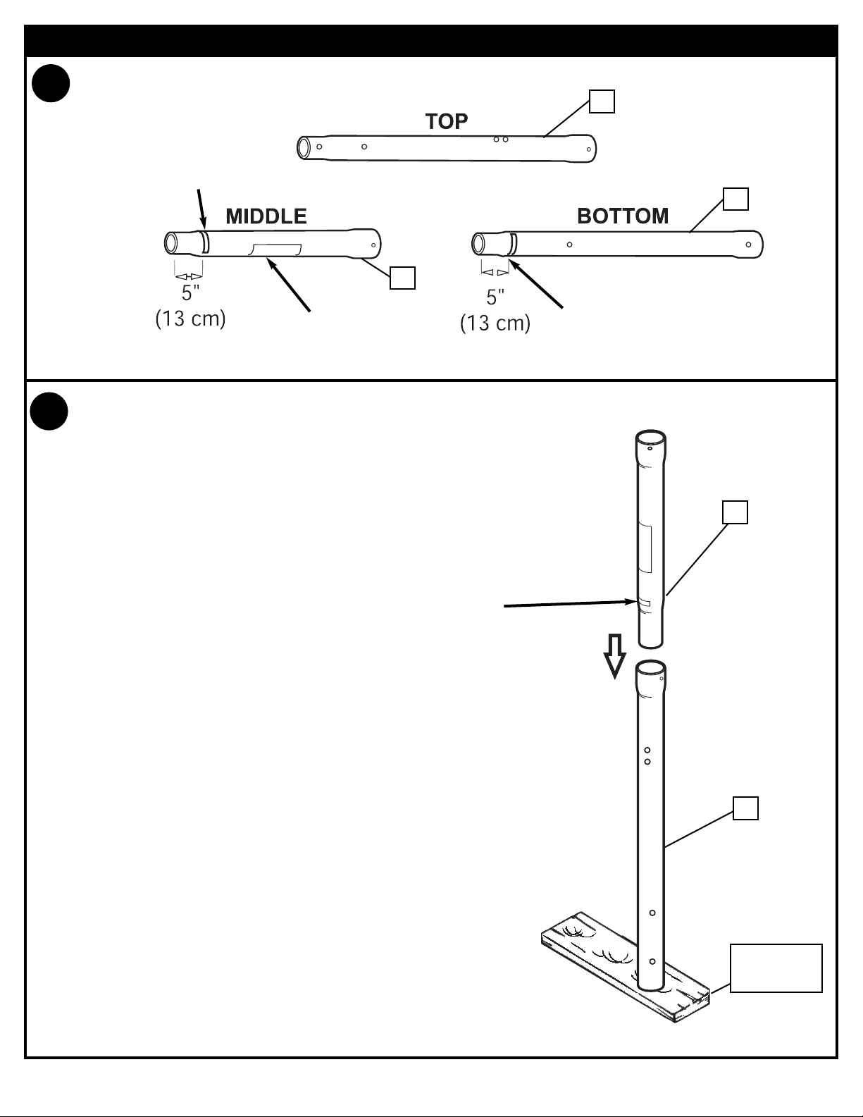
SECTION A: ASSEMBLE THE POLES
2.
WARNING
LABEL
2
1
3
Taped Reference Mark
Taped Reference Mark
1.
Mark pole sections with tape (not supplied) as shown.
Bounce middle pole (2) into top pole section
(1) using a wood scrap as shown until top
pole no longer moves toward pole taped
reference mark on middle pole.
NOTE: Pole sections should have a 3-1/2" (9
cm) minimum overlap.
WOOD SCRAP
(NOT SUPPLIED)
2
1
Taped Reference
Mark
Page 10

10
P/N 211475 01/04
3.
Align top holes of top pole to bottom holes of bottom pole. While maintaining
alignment, bounce top and middle pole assembly (1 & 2) onto lower section (3)
using a wood scrap as shown until they no longer move toward pole identification
mark on bottom pole (3).
1
2
3
WOOD SCRAP
(NOT SUPPLIED)
Taped Reference
Mark
RODS SHOWN ARE
FOR VISUAL
REPRESENTATION
OF ALIGNMENT
AND ARE NOT
SUPPLIED WITH
THE HARDWARE
IMPORTANT!:
Holes in top (1) and
bottom pole (3) sections
MUST align to correctly
position elevator system
toward playing surface.
POLE SECTIONS
SHOULD HAVE A
3-1/2" (9 CM) MINIMUM
OVERLAP.
NOTE:
Page 11

01/04 P/N 211475
11
TOOLS REQUIRED FOR THIS SECTION
HARDWARE USED IN THIS SECTION
(not actual size)
SECTION B: ASSEMBLE THE BASE
This is what your system will look like
when you’ve finished this section:
a Hammer or
Mallet
(2) 1/2” AND (2) 9/16" Wrenches
9/16”
1/2”
AND/OR
(2) Socket Wrenches and Sockets
AND
Item #14
Item #11
Item #9
Item #10
Item #17
Item #13
Item #15
Item #7
Page 12

12
P/N 211475 01/04
1.
2.
Insert axle (5) through wheel bracket (4). Secure wheels (6) to axle using
pushnuts (7). Carefully tap pushnuts onto axle with hammer or mallet
4
6
6
7
7
5
Install wheel assembly to base (8) using bolts(9),
washers(10) and nuts (11) as shown.
10
9
11
10
8
SIDE OF WHEEL WITH
LONGER PLASTIC
AXLE NEEDS TO FACE
THE WHEEL BRACKET.
IMPORTANT!:
Page 13

01/04 P/N 211475
13
11
15
10
4.
Attach pole assembly to base using
carriage bolts (15) washers(10) and nuts
(11) as shown. Two people are required
for this step.
3.
Assemble pole bracket (12)
using bolt (13) and locknut
(14) as shown.
13
12
14
IMPORTANT!:
DO NOT OVER
TIGHTEN
THE CUT CORNERS OF
THE POLE BRACKET
NEED TO FACE
TOWARD THE BACK OF
THE BASE AS SHOWN.
IMPORTANT!:
TWO PEOPLE REQUIRED
FOR THIS PROCEDURE.
FAILURE TO FOLLOW THIS
WARNING COULD RESULT IN
SERIOUS INJURY AND/OR
PROPERTY DAMAGE.
WARNING!
Page 14

14
P/N 211475 01/04
5.
Rotate non-secured ends of tank struts (16) outward to mounting holes in tank as
shown.Secure ends of tank struts (16) to tank as shown. Repeat for opposite side.
9
10
11
10
10
10
14
17
13
16
16
16
6.
Secure tank struts (16) to pole as shown.
Nut should be tightened until flush (even)
with locknuts outer edge. Place cap (17)
over exposed end of bolt as shown.
TWO PEOPLE REQUIRED
FOR THIS PROCEDURE.
FAILURE TO FOLLOW THIS
WARNING COULD RESULT IN
SERIOUS INJURY AND/OR
PROPERTY DAMAGE.
WARNING!
IMPORTANT!:
Page 15

01/04 P/N 211475
15
TOOLS REQUIRED FOR THIS SECTION
HARDWARE USED IN THIS SECTION
(not actual size)
SECTION C: ASSEMBLE THE ELEVATOR & BACKBOARD
This is what your system will look like
when you’ve finished this section:
9/16”
1/2”
3/4”
(2) 1/2”, (2) 9/16"” AND (2) 3/4”
Wrenches
AND/OR
(2) Socket Wrenches and Sockets
Item #31
Item #55
Item #44
Item #11
Item #50
Item #19
Item #29
Item #43
Item #21
Item #22
Item #54
Item #30
Item #59
Item #24
Item #46
Item #60
Page 16

16
P/N 211475 01/04
1
.
Install pole mount bracket (28) and reinforcement bracket (18) with carriage bolts
(22) as shown. Tighten flange nuts (11) completely.
1
28
11
11
18
22
22
2.
Attach spacers (24, 43) to pole mount bracket (28) with bolts (29), washers (44),
and lock nuts (31) as shown. IMPORTANT! Tighten just until washers (44) stop
moving.
28
44
44
31
29
44
44
43
24
24
43
Page 17

01/04 P/N 211475
17
3
.
28
11
27
35
35
26
19
Apply logo and height indicator labels (23) to
adjustment rod (51) as shown. Attach handle
parts (52, 53) to adjustment rod with screw
(55), carriage bolts (54), and flange nuts (11)
as shown.
4.
54
11
11
53
52
55
54
51
23
23
Assemble lanyard (26) to locking pin (27) as shown (FIG A). Attach covers (35) onto
pole mount bracket (28) with carriage bolt (19) and nut (11) as shown.
19
FIG. A
26
27
Loop end of pin
lanyard (26) over
carriage bolt (19)
as it passes
through the pole
mount bracket
(28) during this
assembly.
IMPORTANT!:
Indicator labels
should be applied
as close to holes
as possible to
prevent labels from
being damaged
during height
adjustment.
IMPORTANT!:
Page 18

18
P/N 211475 01/04
Insert handle assembly through pole mount assembly as
shown. Lock pole assembly in place at the 10’ (3.05 m)
mark with pin (27).
27
5.
6.
46
30
31
29
45
60
Install spacers (30) onto backboard brackets (45), with bolts (46, 29) and lock
nuts (60, 31) as shown.
IMPORTANT!:
KEEP HARDWARE LOOSE
UNTIL AFTER STEP 8 IS
COMPLETED.
Page 19

01/04 P/N 211475
19
7.
Attach lower elevator tubes (34) and counter balance spring (48) to backboard
support brackets (45) using spacers (49), bolt (50), and nut (21) as shown.
33
Upper Elevator tube
Toward
Pole
Toward
Board
34
Lower Elevator tube
Toward
Pole
Toward
Board
Identify elevator tubes (33 & 34).
34
21
49
50
34
45
48
49
Page 20

20
P/N 211475 01/04
8.
Starting with nuts (11) flush against bracket (45) secure rim (40) and bracket to
backboard.
IMPORTANT! For spring loaded rim assembly, refer to instructions
included with rim hardware.
NOTE: Rim mounting nuts and bolts supplied with rim hardware.
NOTE: DO NOT use washers here on spring return style rims.
45
11
11
40
11
19
19
21
50
49
49
33
33
45
Refer To
Instructions
Included With Rim
Hardware For Rim
Assembly.
11
41
59
9.
Attach upper elevator tubes (33) to backboard support brackets (45) using
spacers (49), bolt (50), and nut (21) as shown.
IMPORTANT!:
TIGHTEN ALL HARDWARE
FROM STEP 6 - 8 AFTER
THIS ASSEMBLY IS
COMPLETED.
Page 21

01/04 P/N 211475
21
21
21
47
25
34
1
32
32
50
20
34
20
10.
Support pole on sawhorse. Attach backboard assembly to top pole section (1)
as shown. Install pole cap (25). NOTE: Two people are recommended for this
step. Use caution; elevator assembly is heavy.
50
33
20
21
1
21
33
20
32
51
11.
Install upper elevator tubes (33) to triangle plates (32) as shown. Install handle
assembly to lower elevator tubes (34) using bolt (50), spacers (20), and nut (21) as
shown.
NOTE: Before going on to next step, set adjustable system assembly to the 10’
(3.05 m) setting.
50
34
34
20
20
Page 22

22
P/N 211475 01/04
12.
Insert bolt (50) through left side upper elevator tube (33), then stretch spring
(48) onto bolt (50). Insert bolt (50) through right side upper elevator tube (33)
and secure with nut (21).
48
21
50
33
33
USE EYE PROTECTION
WHEN INSTALLING
SPRINGS.
WARNING!
Page 23

01/04 P/N 211475
23
1.
SECTION D: SECURING THE SYSTEM
Roll assembly to desired playing area. Secure assembly to ground using rope (56)
and tie down stake (36). Fill base (8) with water (approx. 40 gallons) and snap fill
caps (37) in place.
56
36
37
8
37
DO NOT LEAVE
ASSEMBLY UNATTENDED
WHEN EMPTY; IT MAY TIP
OVER.
WARNING!
TWO PEOPLE REQUIRED
FOR THIS PROCEDURE.
FAILURE TO FOLLOW THIS
WARNING COULD RESULT IN
SERIOUS INJURY AND/OR
PROPERTY DAMAGE.
WARNING!
ADD TWO GALLONS (7.6
LITERS) OF NON-TOXIC
ANTIFREEZE IN SUBFREEZING CLIMATES.
CAUTION!
Page 24

24
P/N 211475 01/04
SECTION E: INSTALL FRONT COVER
1.
Install front cover (38) by lining up stand-offs along the tank struts. Insert a tie strap
(39) through the top two and bottom two stand offs. Wrap tie straps around tank
struts as shown and secure tightly. Trim excess of tie strap as shown in FIG.A.
38
39
FIG.A
STANDOFFS
Page 25

01/04 P/N 211475
25
1.
Install clips.
CLIP “ARM”
CLIP “BODY”
Insert one “arm” of clip into ram as shown. Twist “body” of
clip slightly so that second “arm” slides over the top of the
first “arm” as shown.
Push in direction indicated by arrows.
Push second “arm” back and into ram as shown.
Twist “body” of clip slightly again to spread “arms” of clip.
Clip “arms” must be flat and touching edge to edge as
shown, not overlapping.
AA
BB
CC
40
57
SECTION F: NET INSTALLATION
USE OF THIS PRODUCT
WITHOUT PROPER
INSTALLATION OF SMART
CLIPS
®
, OR WHEN ALL SMART
CLIPS®ARE NOT PRESENT
COULD RESULT IN BODILY
HARM. BE SURE TO FOLLOW
DIRECTIONS CAREFULLY.
WARNING!
Page 26

26
P/N 211475 01/04
Insert net into bottom of clip as shown.
SIDE VIEW
Twist net until it snaps into position.
Net must be centered through clip.
NET
NETCLIP
SIDE VIEW
NET
NETCLIP
2.
40
57
58
Page 27

01/04 P/N 211475
27
42
1.
Apply Height Adjustment and Moving Label (42) to front of pole, where it is
clearly visible.
SECTION G: APPLY HEIGHT AND MOVING LABEL
HEIGHT ADJUSTMENT
TO ADJUST BACKBOARD:
1. While holding handle, remove pin.
2. Move elevator up or down to
desired height.
3. Replace pin full length to lock
system at desired height.
MOVING SYSTEM
1
2
3
4
1. Adjust basketball backboard
2. While holding pole, rotate
3. Move basketball system to
4. Carefully rotate basketball
5. Reattach ground restraint and
1
3
2
2
height to lowest position.
basketball system forward
until wheels engage with
ground.
desired location.
system upright.
check system for stability.
201252 2/99
Page 28

28
P/N 211475 01/04
SECTION H: HEIGHT ADJUSTMENT
1.
A. While holding handle, remove pin (27).
B. Move elevator up or down to desired height.
C. Replace pin (27) full length to lock system at desired height.
27
A.
B.
C.
51
DO NOT ALLOW
CHILDREN TO
ADJUST HEIGHT.
WARNING!
 Loading...