

Page 1
1
06/03 P/N 211540D
© COPYRIGHT 2000 by HUFFY SPORTS
Toll-Free Customer Service Number for U.S: 1-800-558-5234,
For Canada: 1-800-284-8339,
For Europe: 00 800 555 85234 (Sweden: 009 555 85234),
For Australia: 1-800-333 061
Internet Address: http://www.huffysports.com
Backboard and Rim
Owners Manual
Customer Service Center
• N53 W24700 South Corporate Circle • Sussex, WI 53089 • U.S.A.
REQUIRED TOOLS AND
MATERIALS:
• Step Ladder 8 ft. (2.4 m)
• Adjustable Wrench
• Wrenches: 7/16”, 1/2”, 9/16”, 3/4”
Read and understand
operator's manual before
using this unit.
Failure to follow operating
instructions could result
in injury or damage to
property.
Page 2
2
P/N 211540D 06/03
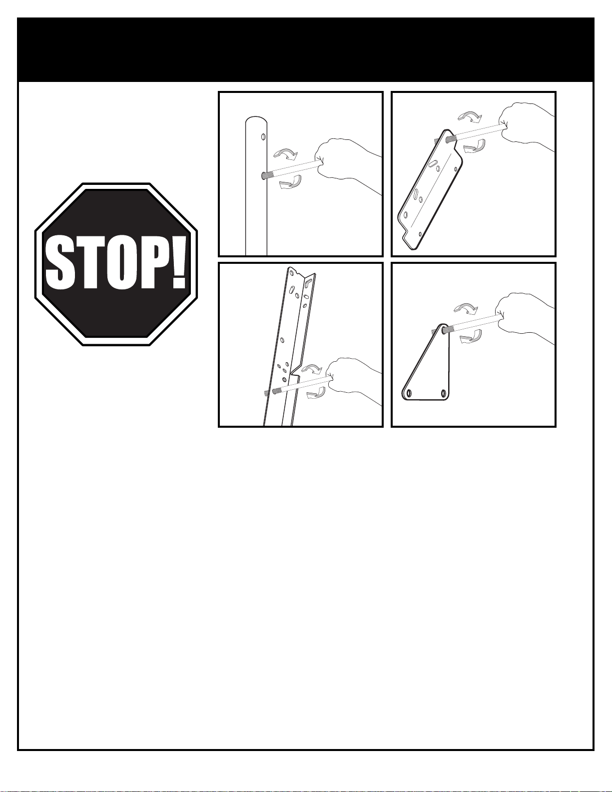
BEFORE YOU START!
To ensure optimal playability of backboard system, a close tolerance fit between the elevator
components and hardware is required. Test fit large bolts into large holes of elevator tubes,
backboard brackets and triangle plates. Carefully rock them in a circular motion to ream out
any excess paint from holes if necessary.
AVANT DE COMMENCER !
Pour garantir l'utilisation optimale du panneau, les composants du système élévateur et la visserie doivent être bien
ajustés (serrés). À titre d'essai, insérez les gros boulons dans les gros trous des tubes du système élévateur, des supports
du panneau et des plaques triangulaires. Basculez-les avec précaution en imprimant un mouvement circulaire pour
éliminer l'excédent de peinture, si nécessaire.
¡ANTES DE COMENZAR!
Para asegurar el óptimo rendimiento del sistema del respaldo en el juego, se requiere un ajuste de tolerancia estrecha
entre los componentes del elevador y el herraje. Pruebe el ajuste de los pernos grandes en los orificios grandes de los
tubos elevadores, soportes del respaldo y placas triangulares. Cuidadosamente muévalos en círculos para eliminar
cualquier exceso de pintura, si es necesario.
VORBEREITENDE MASSNAHMEN
Um sicherzustellen, dass das Korbwandsystem optimal für den Spielbetrieb geeignet ist, müssen die Komponenten der
Verlängerungsvorrichtung und die verschiedenen Befestigungsteile fest miteinander verschraubt werden. Große Schrauben
zur Probe in die großen Löcher der Verlängerungsrohre, Korbwandklammern und Dreiecksplatte stecken und diese
vorsichtig in einer Kreisbewegung hin- und herbewegen, um eventuelle Farbrückstände aus den Bohrungen zu entfernen.
Page 3
06/03 P/N 211540D
3
WARNING
FAILURE TO FOLLOW THESE WARNINGS MAY RESULT
IN SERIOUS INJURY AND/OR PROPERTY DAMAGE.
Owner must ensure that all players know and
follow these rules for safe operation of the unit.
In the U.S.: 1-800-558-5234 and Canada Only: 1-800-284-8339
206118 5/97
See instruction manual for proper installation and
maintenance.
Use caution when performing dunk type activities on this unit.
Do not hang from any part of unit, including backboard,
support braces, rim or net.
Check unit before each use for loose hardware, excessive
wear and signs of corrosion and repair before using.
During play, use extreme caution to keep player's face away
from the backboard, rim or net. Serious injury could occur if
teeth/face come in contact with backboard, rim or net.
During play, do not wear jewelry (rings, watches, necklaces,
etc.) Objects may entangle in net.
·
·
·
·
·
·
SAFETY INSTRUCTIONS
Most injuries are caused by misuse and/or not following instructions.
Use caution when using this system.
• If using a ladder during assembly, use extreme caution.
• Two (2) people are recommended for this operation.
• Check base regularly for leakage. Slow leaks could cause system to tip over
unexpectedly.
• Seat the pole sections properly (if applicable). Failure to do so could allow the pole
sections to separate during play and/or transport of the system.
• Climate, corrosion or misuse could result in system failure.
• Minimum operational height is 6' 6" (1.98 m) to the bottom of backboard.
• This equipment is intended for home recreational use only and NOT excessive
competitive play.
• Read and understand the warning label affixed to pole. Label is shown on page 1.
• The life of your basketball pole depends on many conditions. The climate,
placement of the pole, the location of the pole, exposure to corrosives such as
pesticides, herbicides or salts are all important.
• If technical assistance is required, contact Huffy Sports.
• Adult supervision is recommended when adjusting height.
FAILURE TO FOLLOW THESE SAFETY INSTRUCTIONS MAY RESULT IN
SERIOUS INJURY OR PROPERTY DAMAGE AND WILL VOID WARRANTY.
Owner must ensure that all players know and follow these rules for safe
operation of the system.
To ensure safety, do not attempt to assemble this system without following the
instructions carefully. Proper and complete assembly, use and supervision is
essential for proper operation and to reduce the risk of accident or injury. A high
probability of serious injury exists if this system is not installed, maintained, and
operated properly. Check entire box and inside all packing material for parts
and/or additional instructional material. Before beginning assembly, read the
instructions and identify parts using the hardware identifier and parts list in this
document.
Page 4
4
P/N 211540D 06/03
For more information on assembly, placement, proper
use and maintenance, visit The American Basketball
Council website at http://www.smarthoops.com.
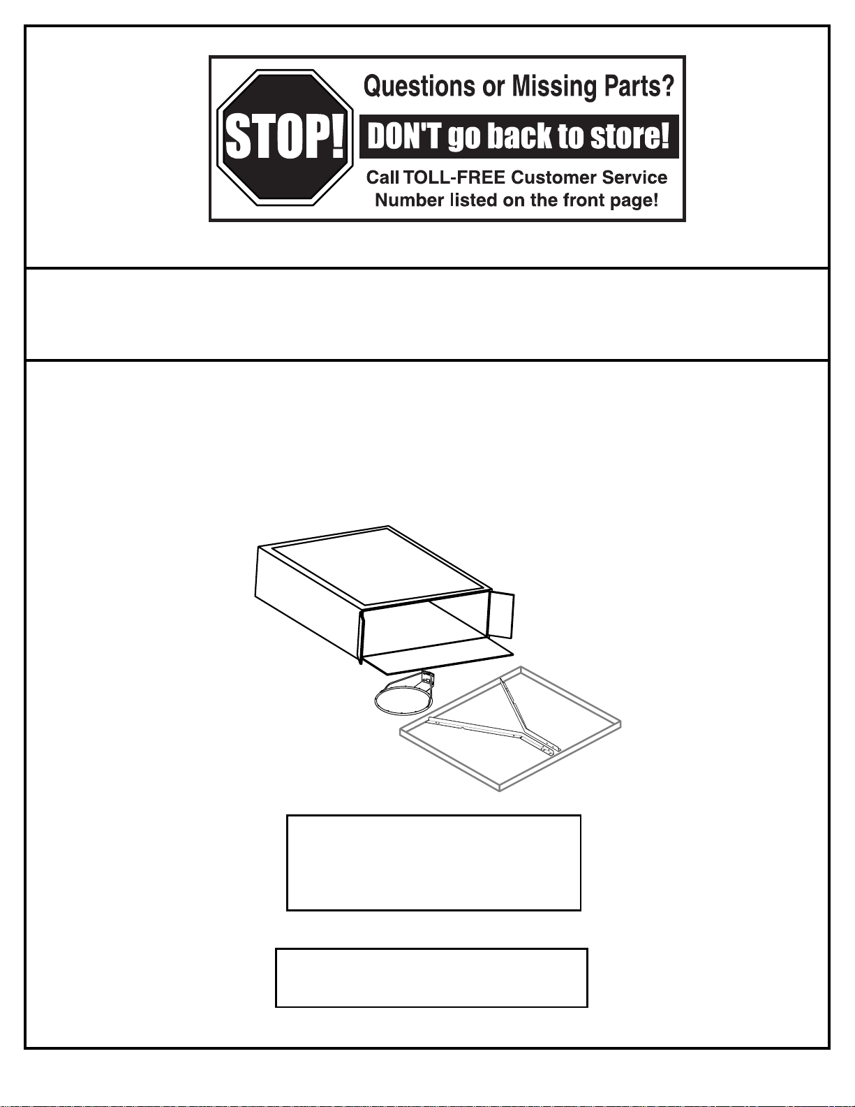
IMPORTANT!
Remove all contents from boxes.
NOTICE TO ASSEMBLERS
ALL Huffy Sports Basketball Systems, including those used for DISPLAYS, MUST be assembled
and ballasted with sand or water according to instructions. Failure to follow instructions could
result in SERIOUS INJURY. It is NOT acceptable to devise a makeshift weight system.
WARRANTY CARD:
Please remember to complete your product
registration form either on-line at:
www.huffysports.com/warrantycard or
mail-in the enclosed postcard.
Page 5
06/03 P/N 211540D
5
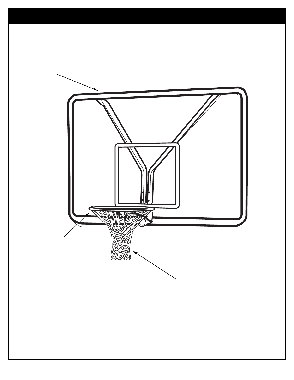
Get to know the basic parts of your basketball system.....
BACKBOARD
FRONT
RIM
NET
Page 6
6
P/N 211540D 06/03
Item Qty. Part No. Description
1 4 202341 “L” Bracket
2 2 200837 Spacer, Plastic
3 6 201107 Bolt, Hex Head, 1/4-20 x 1/2 Long
4 6 203326 Washer, Lock, 1/4
5 6 203228 Nut, 1/4-20
6 8 203100 Hex Flange Nut 5/16-18
7 4 203104 Bolt, Hex Flange, 5/16-18 x 2 Long
8 2 900964 Bracket, Backboard Support
9 2 206360 Bolt, Hex Head, 3/8-16 x 2.625 Long
10 2 200874 Spacer, Steel .402 I.D. x .50 O.D. x 1.5 Long
11 2 201124 Nut, 3/8-16
Item Qty. Part No. Description
12 1 Rim
13 12 201219 Clip, Net Holder, Smart Clips
14 1 Net
15 4 205528 Bolt, Hex Flange, 5/16-18 x 1 Long
16 8 203309 Washer, Flat
17 4 202862 Spacer, Plastic,1.19" Long
18 2 201640 Bolt, Hex, 1/2-13 X 7.25 Long
19 2 206340 Lock Nut, Nylon Insert, 1/2-13
Item #13 (12*)
Item #3 (6)
Item #5 (6)
Item #6 (8)
Item #11 (2)
Item #15 (4)
Item #16 (8)
Item #4 (6)
Item #10 (2)
Item #7 (4)
Item #9 (2)
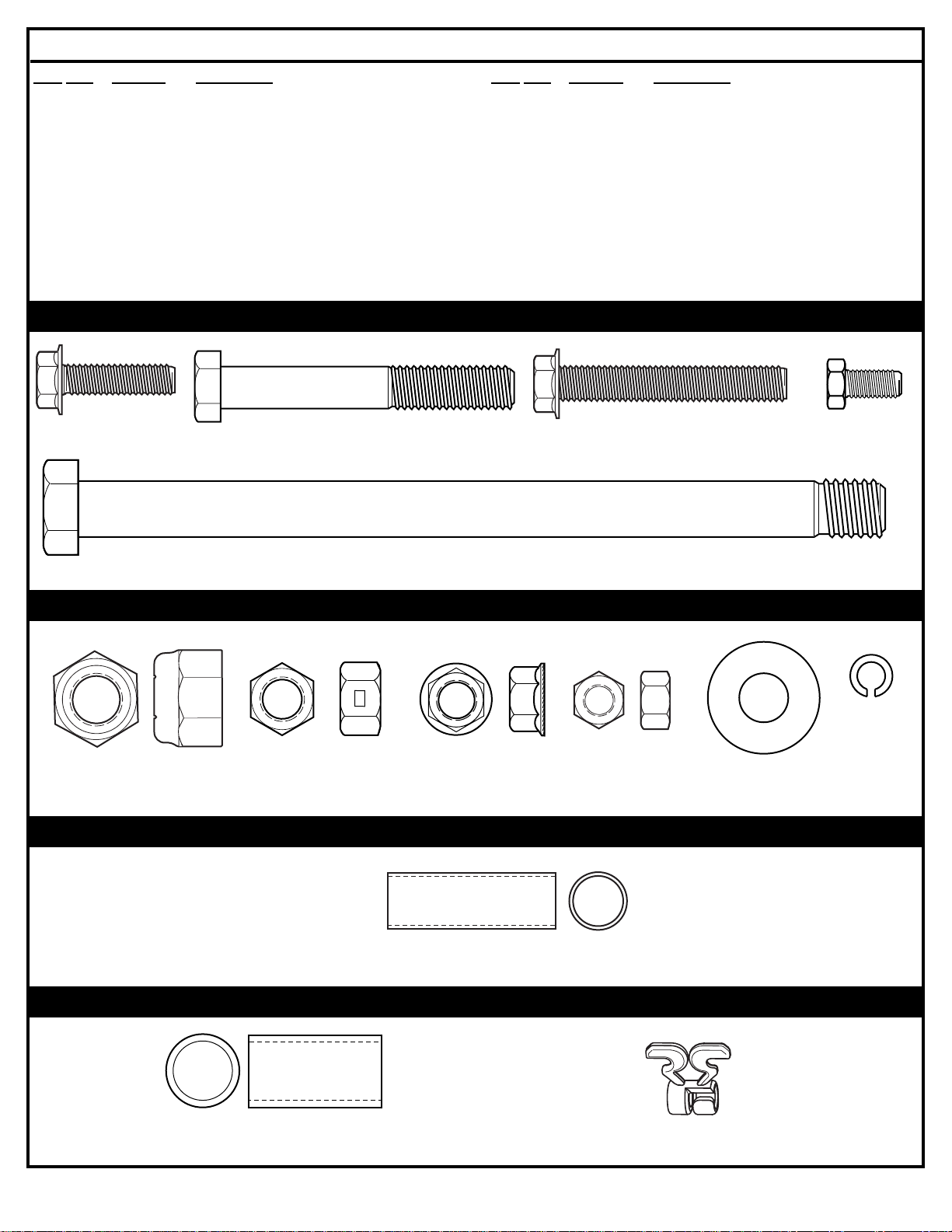
HARDWARE IDENTIFIER (BOLTS)
HARDWARE IDENTIFIER (NUTS & WASHERS)
HARDWARE IDENTIFIER (STEEL SPACERS)
HARDWARE IDENTIFIER (PLASTIC SPACERS & CLIPS)
PARTS LIST (See Hardware Identifiers)
Item #18 (2)
Item #19 (2)
Item #17 (4)
Page 7

06/03 P/N 211540D
7
TOOLS REQUIRED FOR THIS SECTION
HARDWARE USED IN THIS SECTION
(not actual size)
SECTION A: ASSEMBLE THE BACKBOARD AND RIM
3/4", 9/16” and 1/2”
3/4", 9/16” and 1/2”
AND/OR
This is what your system will look like
when you’ve finished this section:
Item #13 (12*)
Item #3 (6)
Item #5 (6)
Item #6 (8)
Item #11 (2)
Item #15 (4)
Item #16 (8)
Item #4 (6)
Item #10 (2)
Item #7 (4)
Item #9 (2)
Item #18 (2)
Item #19 (2)
Item #17 (4)
Page 8

8
P/N 211540D 06/03
IMPORTANT!
For spring loaded rim assembly, refer to instructions included with rim hardware.
IMPORTANT! WRITE DOWN MODEL NUMBER FROM BOX ON PAGE 1 OF THIS OWNERS MANUAL
WARNING: IF YOUR SYSTEM IS EQUIPPED WITH AN ACRYLIC
BACKBOARD, EXAMINE BACKBOARD FOR ANY DAMAGE THAT MAY
HAVE OCCURRED DURING SHIPMENT. CRACKS IN THE BACKBOARD
COULD RESULT IN SUDDEN BREAKAGE. IF BACKBOARD IS DAMAGED
IN ANY WAY PRIOR TO OR AFTER ASSEMBLY, CALL TOLL-FREE
NUMBER FOR FREE REPLACEMENT:
U.S. 1-800-558-5234; CANADA: 1-800-284-8339; http://www.huffysports.com
EXTENSION ARM MOUNT Extension Arm - Not Included
1
7
6
15
2
6
16
5
4
1
3
Peel protective film from
surface of acrylic
backboard prior to use.
NOTE:
NOTE:
We recommend mounting backboard to a solid
material (steel) behind rim area.
IMPORTANT!
For spring loaded rim
assembly, refer to
instructions included with
rim hardware.
1.
Page 9

06/03 P/N 211540D
9
Model 8406 Universal Mounting Bracket is available for purchase
by calling this number: 1-800-558-5234
POLE, ROOF, OR WALL MOUNT
15
15
6
6
WALL MOUNT
3
3
4
5
5
4
POLE MOUNT
IMPORTANT!
For spring loaded rim
assembly, refer to
instructions included with
rim hardware.
Model 8406 Universal
Mounting Bracket
(Not Supplied)
Model 8406
Universal Mounting
Bracket is available
for purchase by
calling this number:
1-800-558-5234
Wall Mount - Not Included
Pole Mount - Not Included
Page 10

10
P/N 211540D 06/03
1
6
1
3
5
ROOF MOUNT
Top View
3
16
5
4
Model 8406 Universal Mounting Bracket
(not supplied) is available for purchase
by calling this number: 1-800-558-5234
4
4
3
5
15
IMPORTANT!
For spring loaded rim
assembly, refer to
instructions included with
rim hardware.
Roof Mount - Not Included
Page 11

06/03 P/N 211540D
11
IMPORTANT!
All Elevator mounts will require this initial step of attaching brackets (8) to the backboard.
ELEVATOR MOUNTS
8
10
10
11
8
8
Peel protective film from
surface of acrylic
backboard prior to use.
NOTE:
8
6
6
15
Use existing elevator
components.
NOTE:
IMPORTANT!
For spring loaded rim
assembly, refer to
instructions included with
rim hardware.
A
SPRING STYLE ELEVATOR MOUNT
IMPORTANT!
It is necessary for all parts to
be installed properly for this
mechanism to work safely
and properly.
Specific Elevator Mount Components Are Not Included
Page 12
12
P/N 211540D 06/03
SPRING STYLE ELEVATOR MOUNT (continued)
8
Use existing elevator
components.
NOTE:
B
BRONZE RATCHET ELEVATOR MOUNT
Use existing elevator
components.
NOTE:
Page 13

06/03 P/N 211540D
13
Use existing elevator
components.
NOTE:
BRONZE RATCHET ELEVATOR MOUNT (continued)
Use existing elevator
components.
NOTE:
Page 14

14
P/N 211540D 06/03
STAMPED RATCHET ELEVATOR MOUNT
C
8
Use existing elevator
components.
NOTE:
Use existing elevator
components.
NOTE:
Page 15

06/03 P/N 211540D
15
Use existing elevator
components.
NOTE:
IMPORTANT!
For spring loaded rim
assembly, refer to
instructions included with
rim hardware.
STAMPED RATCHET ELEVATOR MOUNT (continued)
Page 16

16
P/N 211540D 06/03
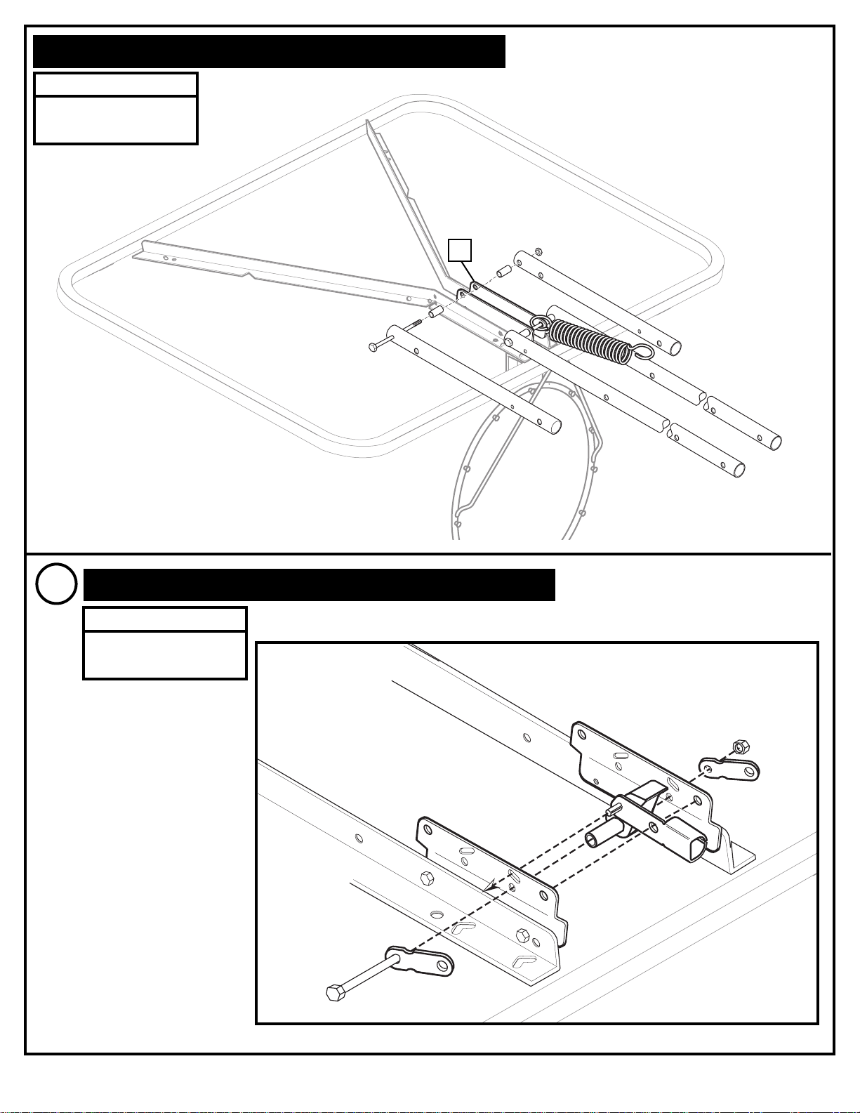
APOLLO ELEVATOR MOUNT
D
Use existing elevator
components.
NOTE:
IMPORTANT!
Remove Y-Frame from elevator portion
½
½
½
STRAIGHT ON VIEW
17
8
Upper Tube
Lower Tube
Upper Tube
Lower Tube
17
17
18
19
17
Page 17

06/03 P/N 211540D
17
2.
Install clips.
CLIP “ARM”
CLIP “BODY”
Insert one “arm” of clip into ram as shown. Twist “body” of clip
slightly so that second “arm” slides over the top of the first “arm”
as shown.
Push in direction indicated by arrows.
Push second “arm” back and into ram as shown.
Twist “body” of clip slightly again to spread “arms” of clip.
Clip “arms” must be flat and touching edge to edge as shown,
not overlapping.
AA
BB
CC
12
13
USE OF THIS PRODUCT
WITHOUT PROPER
INSTALLATION OF
SMART CLIPS, OR WHEN
ALL SMART CLIPS ARE
NOT PRESENT COULD
RESULT IN BODILY
HARM. BE SURE TO
FOLLOW DIRECTIONS
CAREFULLY.
WARNING!
Page 18

18
P/N 211540D 06/03
Insert net into bottom of clip as shown.
SIDE VIEW
Twist net until it snaps into position.
Net must be centered through clip.
NET
NETCLIP
SIDE VIEW
NET
NETCLIP
NET INSTALLATION
5.
12
13
14
 Loading...