

Page 1
The Hubbell Intelligent Radio Locomotive Systems features a microcomputer with status
display and built-in diagnostics along with
our high speed, digital, biphase modulation to provide reliable, efficient and
economical operation
of diesel-electric locomotives from a portable transmitter.
By operating the
transmitter switches, a radio message is sent to the locomotive
mounted receiver to control the direction and speed of the locomotive. Additional data bits are available to perform special auxiliary
functions such as sounding of horn,
application of brakes or control of
couplers.
31200
Brochure 31200
November 1996
New
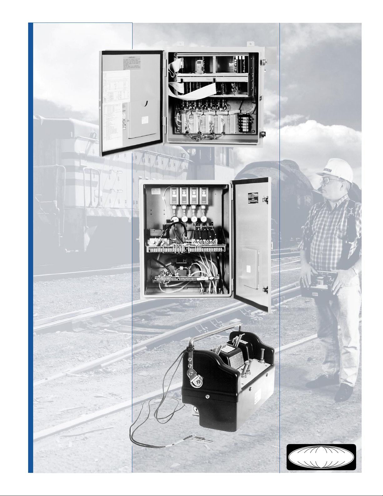
Receiver Cabinet
Each radio control system operates
on a licensed frequency in the 72–
76 MHz or the 450–470 MHz
bands. The receiver is crystal controlled. A synthesized 72–76 MHz
receiver is also available.
Benefits
• Easy to Maintain — Self diagnos-
tics identify problem areas via the
status display.
• Fast Response — High Speed data
rate offers fast, responsive operation.
• Frequency Conservation — Up to
four systems can share the same
radio frequency, which also saves
on spare parts requirements.
• Cost Reduction — Operating crew
is reduced on each shift. Payback
is realized in just a few months.
• Better Visibility — Remote control
takes the operator out of the cab
providing him with improved visibility and total control from grade level.
• Simple Operation — Portable,
lightweight transmitter is easier to
operate than manual controls.
Pneumatics Cabinet
Midsize Transmitter
(See Spec 31110)
Hubbell 72 & 450 MHz Remote Control System for Locomotive Applications
M icroprocessor Radi o Locomotiv e Control
HUBBELL
Page 2
System Features
Secure Control — Hubbell’s biphase data transmission scheme and Cyclic Redundency Check code
(CRC) prevent false motions and provides for controlled shutdowns. Digital messages are checked for
address, format, and content before any motion or
function is activated. While in motion, check circuits
continuously monitor the received message and the
quality of the RF carrier signal. Any error or loss of signal integrity will de-energize all controlled functions
and apply the brakes.
Frequency Conservation — It is possible to have several transmitters operating in the same area, on the
same frequency, with practically no interference because of different transmission rates for each transmitter. The unique address code of each transmitter and
receiver assures that only the matching receiver responds to the radio commands. All other signals on
the same frequency are ignored.
“QSR” Design — Hubbell’s Quality, Serviceable, Reli-
able product design philosophy is evident with the Locomotive Control System. Protective circuits are employed to prevent transients or extreme voltage fluctuations from damaging components. The modular, solid
state design, housed in NEMA 12 enclosures, provides reliable operation and long service life under
the most rugged and extreme conditions. Spares requirements are significantly reduced by virtue of the
shared frequency capability and modular design.
Efficient and Flexible — The high speed data transmission technique provides faster and thereby more
responsive operation. A lightweight, durable plastic
transmitter is comfortable and easy to operate. A
manual/remote transfer switch can be provided for
isolation between the manual and remote control
components.
Security of the received signal and any resulting control actions are safeguarded as follows:
• The received signal must be of the proper
frequency.
• The received message must have the proper ad-
dress and must be in the correct format.
• The receiver calculated CRC code must be identi-
cal to the CRC code calculated by the transmitter
and sent as part of each message.
• The preceding items must be met and all transmitter
lever switches must be centered before the locomotive can be activated and the brakes released.
• To continue or change an energized function, re-
quires the receipt of a “valid message” prior to
time-out of the message timer (2 sec). If no valid
message is received, the system turns all outputs
off and applies the brakes.
Features
Microcomputer
Hubbell’s system uses a
single board micro computer which converts the
biphase data from the radio receiver, decodes and
verifies the message by
checking for errors. The
computer generates the
control outputs to the l/O
interface boards. The address and message time
interval is user programmable. A hardware
watchdog timer monitors
the program operation
and resets the processor if
the program fails to execute properly .
On-Board Diagnostics
The computer board employs continuous diagnostics. System status is displayed on a two digit alpha numeric display .
Upon power-up, the initialization test checks the I/O
boards, internal random
access memory (RAM), the
motion controlling solid
state relays, and the pneumatic system.
When a fault is detected,
the computer will stop the
locomotive and the error
will be displayed. The
fault must be corrected
before operation can
continue.
After initialization, the
watchdog circuit, the solid
state relays and the pneumatic functions are continuously monitored. Any operational, communications
or run mode faults will
shutdown the locomotive,
apply the brakes, and display a fault code.
Input/Output Board
The l/O board accepts
the control outputs from the
microcomputer and converts them into driving outputs for the solid state relays. The l/O board also
accepts input from the solid state relays feedback
circuits and provides this
information to the controller
for diagnostic purposes.
Emergency Stop Board
The Emergency Stop
board monitors the Emergency Stop pushbuttons
mounted in the locomotive, the main air reservoir
pressure, oil pressure, and
coolant water temperature. If any of these functions are abnormal, a signal is given to the micro to
shut down the locomotive
and apply the brakes.
DC Solid State Output
Each solid state relay
board has eight circuits to
drive the 24VDC interfacing relays and solenoid
valves to control the locomotive functions.
Electro-Mechanical
Relays
Electro-Mechanical Relays
are used to control locomotive direction, throttle,
head lamps, and Lintern
lights. The Lintern lights
provide operations status
information for the remote
operator.
Sensing Boards
Each sensing board monitors up to eight solid state
relay outputs and/or pressure switches. This provides complete feedback
to the micro on relay and
pressure switch status.
Receiver Cabinet
The electronics cabinet is
of NEMA 12 construction
and houses the power
supply , the radio receiver,
digital decoding logic
cards, solid state drivers
and the output relays.
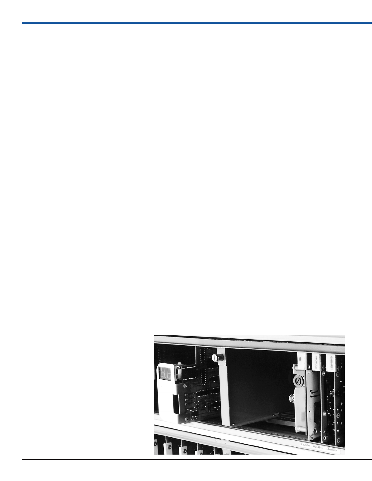
The receiver, digital logic
decoding circuits and the
solid state drivers plug
into common card cages. Edgemounted LED’s
on the circuit boards simplify system troubleshooting and maintenance
tasks. All modules are removable from the front
and the card cage is
hinged to provide access
to backplane wiring.
Solid state drivers or output relays operate the lo-
• Two separate “watchdog timers” assure that all
outputs are switched off in case of a receiver
malfunction.
Page 3

comotive magnetics and
pneumatic systems in response to decoded control
commands. The configuration of the manual control
switches is duplicated and
wired to industrially rated
terminals for interconnection to the locomotive controls. A manual-remote
transfer switch is provided
to completely isolate the
radio system from the manual controllers.
The receiver antenna is
normally mounted on the
locomotive cab, and sufficient co-axial cable is provided to connect the antenna to the radio receiver
Pneumatic Cabinet
The pneumatics enclosure
is of NEMA 12 construction and houses the pneumatic controls for the remote operation of the locomotive. The locomotive
throttle, independent
brakes, and the train line
brakes are normally operated via binary pneumatic
valves for control of the air
pressure. Other functions
and the horn are controlled by solenoid valves.
This cabinet also contains
the pressure switches for
main air, independent
brakes air, train line
brakes air, and throttle air.
module in the cabinet.
Hubbell Offers
• Factory Assembled — the transmitter, receiver,
and pneumatics cabinets are completely assembled and wired at the Hubbell factory.
• System Test — the entire system is tested for a
minimum of 48 hours prior to shipment.
• Installation and Commissioning — Installation
is accomplished quickly . Transfer switch is
pre-wired and labeled, interconnecting terminals are provided to simplify installation. A
Hubbell field engineer can be contracted for
installation and final check-out.
• Customer Support — Hubbell provides a
complete documentation package including
drawings, operating manuals, service manuals, spare parts, training and experienced field
service engineers.
Specifications
Supply Voltage ......................... 12VDC, 24VDC, 36VDC or 72VDC
Internal Power Requirements ........ +11.9–13.1VDC & +4.5–6.5VDC
Operating Temperature .............. –22°F (–30°C) to 140°F (+60°C)
Radio Receiver
Frequency Range ...................... 72–76 MHz or 450–470 MHz
Channel Availability .................. as required by user
Frequency Stability .................... ±5 ppm
Sensitivity ................................ 1 µv @ 20 dB quieting
Data Reception......................... compatible with existing transmitters
Modulation .............................. biphase
Baud Rate ............................... 4800 bps
Message Format ....................... preamble, sync pattern, start flag, address, control, CRC
check code
Control Section
Single board computer consisting of 80C31BH controller, 64k EPROM, EPLD containing circuits for message synchronizing, and processor watchdog
Switches ................................. 8 position address dip, 4 position message timer dip
Indicators ................................ 2 digit display (7 segment LED) for self diagnostics & error
conditions
Firmware ................................. written in 8031 assembly language structured for ease of
customization of output control
Functions ................................. message input address decoding, error checking, control
bit decoding, output control self diagnosis
Paralleled I/O ......................... basic system uses single board, up to three additional
boards may be added
Output per board...................... 48 software programmable for input or output with
readback on all outputs
Driver per output ....................... TTL compatible for up to 25mA sink
DC Output Section
Solid state relay PC boards in card cage.
Type....................................... Opto Isolated
Indicators ................................ Red: output activated
Output Voltage ......................... 24VDC
Input Voltage............................ 4.5–6.5Vdc, active high
Load....................................... 0.5A, 24VDC, inductive
Isolation .................................. 1500V
Input Board
Input 24 VDC sensing PC board in card cage.
Indicator ................................. Red: input activated
Input ....................................... 24VDC nominal
Isolation .................................. 1500V input to output & between circuits
Output .................................... Opto-isolated; active low
HUBBELL
Page 4

Key
Components
Crane mounted NEMA 12
receiver cabinet with power
converter, radio receiver, micro controller board, Input/
Output board and solid state
output relays.
1. NEMA T ype 12
Receiver Cabinet
2. Radio/Micro Card
Cage
3. Micro Controller
Card with two digit
display .
4. Input/Output Card
5. RF Receiver Module
6. IF Receiver Board
7. Data Demodulator
Board
8. Solid State Relay
Board
9. Fuse Blocks
10. Relay Panel
11. Terminal Blocks for
Interconnection
12. Low V oltage Power
Supply Panel
13. T ransfer Switch
Local/Radio
14. Pressure Switch
15. Pressure Gauge
16. Terminal Boards
17. Air Cutoff Valve
18. Binair V alve
19. Pneumatic Valves
20. NEMA T ype 12
Pneumatics Cabinet
Microprocessor Locomotive ControlPneumatic Power Pack
HUBBELL
JPS-1196-.5M © 1996
Printed in U.S.A.
24.00" 12.00"1.16"
30.00"
4301 Cheyenne Drive • Archdale, NC 27263
(336) 434-2800 • Fax (336) 434-2801
24.00" 12.00"1.16"
24.00"
Hubbell Industrial Controls, Inc.
a subsidiary of Hubbell Incorporated
50 Edwards Street, Madison, Ohio 44057
Telephone (440) 428-1161 • FAX (440) 428-7635
 Loading...