

Huawei RRU5909, RRU5309w, RRU3959a, RRU5309 Installation Manual

RRU5909&RRU5309&RRU5309w&RR
U3959a Installation Guide
Contents
7.2.2 RRU5909&RRU5309&RRU5309w&RRU3959a Installation Guide
7.2.2.1 Changes in RRU5909&RRU5309&RRU5309w&RRU3959a Installation Guide
7.2.2.2 Installation Preparations
7.2.2.2.1 Reference Documents
7.2.2.2.2 Tools and Instruments
7.2.2.2.3 Skills and Requirements for Onsite Personnel
7.2.2.3 Information About the Installation
7.2.2.3.1 RRU Exterior
7.2.2.3.2 RRU Ports
7.2.2.3.3 RRU Indicators
7.2.2.3.4 Installation Scenarios
7.2.2.3.5 Installation Clearance Requirements of an RRU
7.2.2.3.5.1 Clearance for a Single RRU
7.2.2.3.5.2 Clearance for Three or More RRUs
7.2.2.3.5.3 Installation Spacing Between RRUs
7.2.2.4 Unpacking the Equipment
7.2.2.5 Installation Process
7.2.2.6 Hoisting an RRU and Related Cables onto a Tower
7.2.2.6.1 Hoisting an RRU onto a Tower
7.2.2.6.2 Hoisting Optical Fibers onto a Tower
7.2.2.6.3 Hoisting Power Cables onto a Tower
7.2.2.7 Installing the RRU
7.2.2.7.1 Mounting Kits for an RRU
7.2.2.7.2 Installing the RRU on a Pole
7.2.2.7.2.1 Installing a Single RRU
7.2.2.7.2.2 Installing Two RRUs
7.2.2.7.2.3 Installing Three or More RRUs
7.2.2.7.3 Installing an RRU on U-steel
7.2.2.7.4 Installing an RRU on Angle Steel
7.2.2.7.5 Installing an RRU on a Wall
7.2.2.7.6 Installing an RRU on an IFS06
7.2.2.8 Installing RRU Cables
7.2.2.8.1 Cabling Requirements
7.2.2.8.2 RRU Cable Connections
7.2.2.8.3 Installing RRU Cables
7.2.2.8.4 RRU Cable List
7.2.2.8.5 Installing an RRU PGND Cable
7.2.2.8.6 Installing an RRU RF Jumper
7.2.2.8.7 Installing an RRU AISG Multi-Wire Cable and AISG Extension Cable
7.2.2.8.8 Opening the Cover Plate of an RRU Cabling Cavity
7.2.2.8.9 Installing a CPRI Optical Fiber
7.2.2.8.10 Installing an RRU power cable
7.2.2.8.11 Closing the Cover Plate of an RRU Cabling Cavity
7.2.2.9 Checking the RRU Hardware Installation
7.2.2.10 Powering On an RRU
7.2.2.11 Appendix
7.2.2.11.1 Adding a Female Fast Connector(Pressfit Type) to the RRU Power Cable on the RRU Side
7.2.2
RRU5909&RRU5309&RRU5309w&RRU3959
a Installation Guide
Purpose
This document describes the process of installing DC blade
RRU5909&RRU5309&RRU5309w&RRU3959a(referred to as RRU in this document). RRU is
short for remote radio unit.
Product Versions
The following table lists the product version related to this document for RRU5909&RRU3959a.
Product Name
Solution Version
Product Version
RRU5909&RRU3959a
V100R010C10 and later versions
The following table lists the product version related to this document for RRU5309&RRU5309w.
Product Name
Solution Version
Product Version
RRU5309&RRU5309w
V100R011C10 and later versions
Intended Audience
This document is intended for:
Base station installation engineers
Organization
Changes in RRU5909&RRU5309&RRU5309w&RRU3959a Installation Guide

This section describes the changes in the RRU5909&RRU5309&RRU5309w&RRU3959a
Installation Guide.
Installation Preparations
This chapter describes the reference documents, tools, and instruments that must be ready
before the installation. In addition, it specifies the skills and prerequisites that installation
engineers must have.
Information About the Installation
Before installing an RRU, you must be familiar with its exterior, ports, indicators,
installation scenarios, and installation clearance requirements.
Unpacking the Equipment
This chapter describes how to unpack and check the delivered equipment to ensure that all
the materials are included and intact.
Installation Process
The installation process involves installing an RRU and RRU cables, checking the RRU
hardware installation, and powering on an RRU.
Hoisting an RRU and Related Cables onto a Tower
This section describes the procedure for hoisting an RRU and related cables onto a tower and
the precautions that must be taken.
Installing the RRU
This chapter describes the procedure for installing the RRU. The procedure for installing the
RRU varies depending on installation options.
Installing RRU Cables
This chapter describes the procedure for installing RRU cables.
Checking the RRU Hardware Installation
Powering On an RRU
After all the devices are installed, check the power-on status of an RRU.
Appendix
Huawei Proprietary and Confidential Copyright © Huawei Technologies Co., Ltd.
Huawei Proprietary and Confidential
Copyright © Huawei Technologies Co., Ltd.
Next topic >
7.2.2.1 Changes in
RRU5909&RRU5309&RRU5309w&RRU3959
a Installation Guide
This section describes the changes in the RRU5909&RRU5309&RRU5309w&RRU3959a
Installation Guide.
09 (2018-05-30)
This is the ninth official release.
Compared with Issue 08 (2018-04-30), this issue does not include any new information.
Compared with Issue 08 (2018-04-30), this issue includes the following change.
Topic
Change Description
The whole document
Modified the figures showing the mounting kits for
an RRU, which have been modified.
Compared with Issue 08 (2018-04-30), no information is deleted from this issue.
08 (2018-04-30)
This is the eighth official release.
Compared with Issue 07 (2018-03-20), this issue does not include any new information.
Compared with Issue 07 (2018-03-20), this issue includes the following change.
Topic
Change Description
Installation Scenarios
Added the installation restriction for RRU5309w
external antennas.
Compared with Issue 07 (2018-03-20), no information is deleted from this issue.
07 (2018-03-20)
This is the seventh official release.
Compared with Issue 06 (2018-01-30), this issue does not include any new information.
Compared with Issue 06 (2018-01-30), this issue includes the following change.
Topic
Change Description
RRU Cable Connections
Optimized the descriptions in some sections. No
technical change is involved.
Compared with Issue 06 (2018-01-30), no information is deleted from this issue.
06 (2018-01-30)
This is the sixth official release.
Compared with Issue 05 (2017-09-20), this issue does not include any new information.
Compared with Issue 05 (2017-09-20), this issue includes the following change.
Topic
Change Description
The whole document
Added information about the RRU3959a.
Compared with Issue 05 (2017-09-20), no information is deleted from this issue.
05 (2017-09-20)
This is the fifth official release.
Compared with Issue 04 (2017-08-30), this issue does not include any new information.
Compared with Issue 04 (2017-08-30), this issue includes the following change.
Topic
Change Description
RRU5909&RRU5309&RRU5309w&RRU3959a Installation
Guide
Updated the required product versions and added
support of the RRU by the DBS5900.
Compared with Issue 04 (2017-08-30), no information is deleted from this issue.
04 (2017-08-30)
This is the fourth official release.
Compared with Issue 03 (2017-06-30), this issue does not include any new information.
Compared with Issue 03 (2017-06-30), this issue includes the following change.
Topic
Change Description
The whole document
Added information about the RRU5309 and
RRU5309w.
Compared with Issue 03 (2017-06-30), no information is deleted from this issue.
03 (2017-06-30)
This is the third official release.
Compared with Issue 02 (2017-06-05), this issue does not include any new information.
Compared with Issue 02 (2017-06-05), this issue includes the following change.
Topic
Change Description
Hoisting an RRU onto a Tower
Added descriptions of the OPM50M(Ver.B).
Compared with Issue 02 (2017-06-05), no information is deleted from this issue.
02 (2017-06-05)
This is the second official release.
Compared with Issue 01 (2017-05-20), this issue does not include any new information.
Compared with Issue 01 (2017-05-20), this issue includes the following change.
Topic
Change Description
Installing a CPRI Optical Fiber
Added the following precaution for adding an optical
module: Before connecting the optical fiber to the
optical module, keep the dustproof cap in the port of
the optical module.
Compared with Issue 01 (2017-05-20), no information is deleted from this issue.
01 (2017-05-20)
This is the first official release.
Compared with Draft C (2017-04-20), this issue does not include any new information.
Compared with Draft C (2017-04-20), this issue does not include any changes.
No information in Draft C (2017-04-20) is deleted from this issue.
Draft C (2017-04-20)
This is a draft.
Compared with Draft B (2017-03-10), this issue includes the following change.
Topic
Change Description
RRU5909&RRU5309&RRU5309w&RRU3959a Installation
Guide
Updated the RRU solution version and product
version.
Compared with Draft B (2017-03-10), this issue does not include any new information and no
information is deleted from this issue.
Draft B (2017-03-10)
This is a draft.
Compared with Draft A (2017-01-20), this issue includes the following changes.
Topic
Change Description
Installation Scenarios
Installation Clearance Requirements of an RRU
Installing the RRU
Installing RRU Cables
Optimized figures related to RRU exterior in these
sections.

Compared with Draft A (2017-01-20), this issue does not include any new information and no
information is deleted from this issue.
Draft A (2017-01-20)
This is a draft.
Huawei Proprietary and Confidential Copyright © Huawei Technologies Co., Ltd.
Huawei Proprietary and Confidential
Copyright © Huawei Technologies Co., Ltd.
Next topic >
7.2.2.2 Installation Preparations
This chapter describes the reference documents, tools, and instruments that must be ready before the
installation. In addition, it specifies the skills and prerequisites that installation engineers must have.
Reference Documents
Before the installation, you must be familiar with reference documents.
Tools and Instruments
This section describes the tools and instruments that must be prepared before the remote
radio unit (RRU) installation.
Skills and Requirements for Onsite Personnel
Onsite personnel must be qualified and trained. Before performing any operation, onsite
personnel must be familiar with correct operation methods and safety precautions.
Huawei Proprietary and Confidential Copyright © Huawei Technologies Co., Ltd.
Huawei Proprietary and Confidential
Copyright © Huawei Technologies Co., Ltd.
< Previous topic Next topic >
7.2.2.2.1 Reference Documents
Before the installation, you must be familiar with reference documents.
The following reference documents are required during RRU installation:
• Safety Information
• RRU5909&RRU5309&RRU5309w&RRU3959a Hardware Description
• DBS3900 Installation Guide or DBS5900 Installation Guide
NOTE:
For details about RRU auxiliary devices, see "RRU Auxiliary Devices" in the corresponding RRU hardware description.
Parent Topic: Installation Preparations
Huawei Proprietary and Confidential Copyright © Huawei Technologies Co., Ltd.
Huawei Proprietary and Confidential
Copyright © Huawei Technologies Co., Ltd.
Next topic >
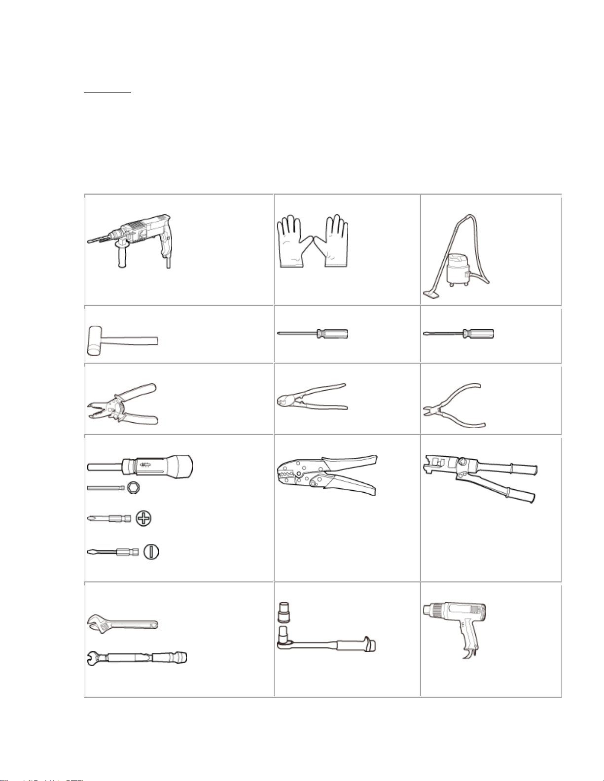
7.2.2.2.2 Tools and Instruments
This section describes the tools and instruments that must be prepared before the remote radio unit
(RRU) installation.
Hammer drill (φ 12 bit, a φ 14 bit)
ESD gloves
Vacuum cleaner
Rubber mallet
Phillips screwdriver
(M3 to M6)
Flat-head screwdriver
(M3 to M6)
Wire stripper
Cable cutter
Diagonal pliers
Torque screwdriver
5 mm (0.2 in.)
(M3 to M6)
(M3 to M6)
Power cable crimping tool
Hydraulic pliers
Adjustable wrench (open mouth ≥ 32 mm
[1.26 in.])
Torque wrench
Open mouth: 16 mm (0.63 in.), 17 mm
(0.67 in.), 19 mm (0.75 in.), 21 mm (0.83
Torque socket
(M8, M10)
Heat gun
in.), 22 mm (0.87 in.), and 32 mm (1.26
in.)
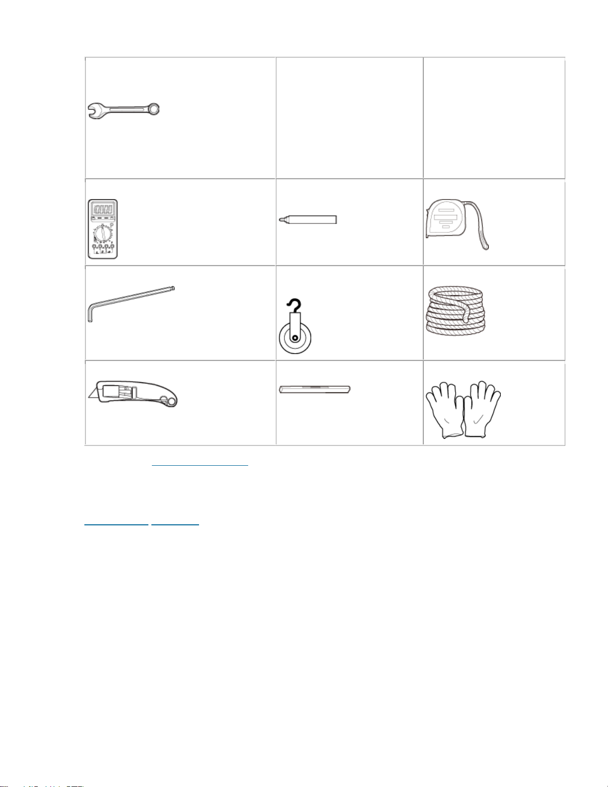
Combination wrench
Open mouth: 16 mm (0.63 in.), 17 mm
(0.67 in.), 19 mm (0.75 in.), 21 mm (0.83
in.), 22 mm (0.87 in.), and 32 mm (1.26
in.)
Multimeter
Marker (diameter ≤ 10 mm
[0.39 in.])
Measuring tape
Inner hexagon wrench
5 mm (0.2 in.)
Fixed pulley (weight-bearing
capacity > 500 kg or 1102.5 lb)
Lifting sling
Utility knife
Level
Protective gloves
Parent Topic: Installation Preparations
Huawei Proprietary and Confidential Copyright © Huawei Technologies Co., Ltd.
Huawei Proprietary and Confidential
Copyright © Huawei Technologies Co., Ltd.
< Previous topic Next topic >
7.2.2.2.3 Skills and Requirements for Onsite
Personnel
Onsite personnel must be qualified and trained. Before performing any operation, onsite personnel
must be familiar with correct operation methods and safety precautions.
Before the installation, pay attention to the following items:
• The customer's technical engineers must be trained by Huawei and be familiar with the proper
installation and operation methods.
• The number of onsite personnel depends on the engineering schedule and installation
environment. Generally, only three to five onsite personnel are necessary.

Parent Topic: Installation Preparations
Huawei Proprietary and Confidential Copyright © Huawei Technologies Co., Ltd.
Huawei Proprietary and Confidential
Copyright © Huawei Technologies Co., Ltd.
< Previous topic
7.2.2.3 Information About the Installation
Before installing an RRU, you must be familiar with its exterior, ports, indicators, installation
scenarios, and installation clearance requirements.
RRU Exterior
This section describes the exterior and dimensions of an RRU.
RRU Ports
This section describes ports on the RRU panels. An RRU has a bottom panel, cabling cavity
panel, and indicator panel.
RRU Indicators
This section describes six indicators on an RRU. They indicate the running status of the
RRU.
Installation Scenarios
An RRU can be installed on a pole, U-steel, angle steel, wall, or IFS06. Installation scenarios
must meet heat-dissipation and waterproofing requirements of the RRU.
Installation Clearance Requirements of an RRU
This section describes the requirements for the installation clearance of a single RRU and
multiple RRUs and the requirements for the installation spacing between RRUs.
Huawei Proprietary and Confidential Copyright © Huawei Technologies Co., Ltd.
Huawei Proprietary and Confidential
Copyright © Huawei Technologies Co., Ltd.
< Previous topic Next topic >
7.2.2.3.1 RRU Exterior
This section describes the exterior and dimensions of an RRU.
Figure 1 shows the exterior of an RRU.

Figure 1 RRU exterior
Figure 2 shows RRU dimensions.
Figure 2 RRU dimensions
You can obtain the RRU name, RRU frequency band and power supply information from the
nameplate on the cover plate. Figure 3 shows the positions of the nameplate on the RRU.
NOTE:
The actual nameplate may differ from what is shown in the figure.
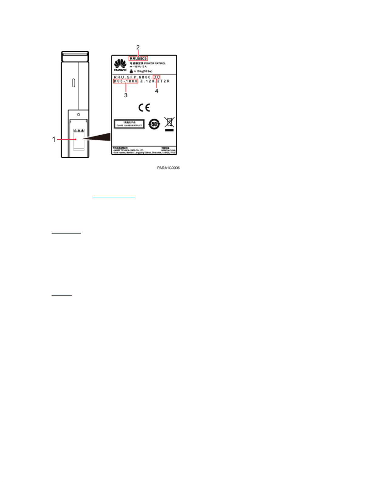
Figure 3 Positions of the nameplate
(1) Nameplate
(2) Module name
(3) Frequency band
(4) Power supply type
Parent Topic: RRU Introduction
Huawei Proprietary and Confidential Copyright © Huawei Technologies Co., Ltd.
Huawei Proprietary and Confidential
Copyright © Huawei Technologies Co., Ltd.
Next topic >
7.2.2.3.2 RRU Ports
This section describes ports on the RRU panels. An RRU has a bottom panel, cabling cavity panel,
and indicator panel.
Figure 1 shows the ports on the RRU panels.
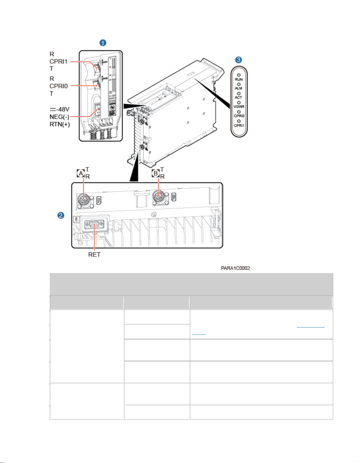
Figure 1 Ports on the RRU panels
Table 1 Ports and indicators on the RRU panels
Item
Silkscreen
Remarks
(1) Ports in the cabling
cavity
RTN(+)
Power supply socket, For details about RRU power
cable appearance and specifications, see RRU Power
Cable.
NEG(-)
CPRI0
Optical/electrical port 0, connected to the BBU or an
upper-level RRU
CPRI1
Optical/electrical port 1, connected to a lower-level
RRU or the BBU
(2) Bottom ports
A T/R
TX/RX port A (4.3-10 female connector), supporting
RET signal transmission
B T/R
TX/RX port B (4.3-10 femalet connector)
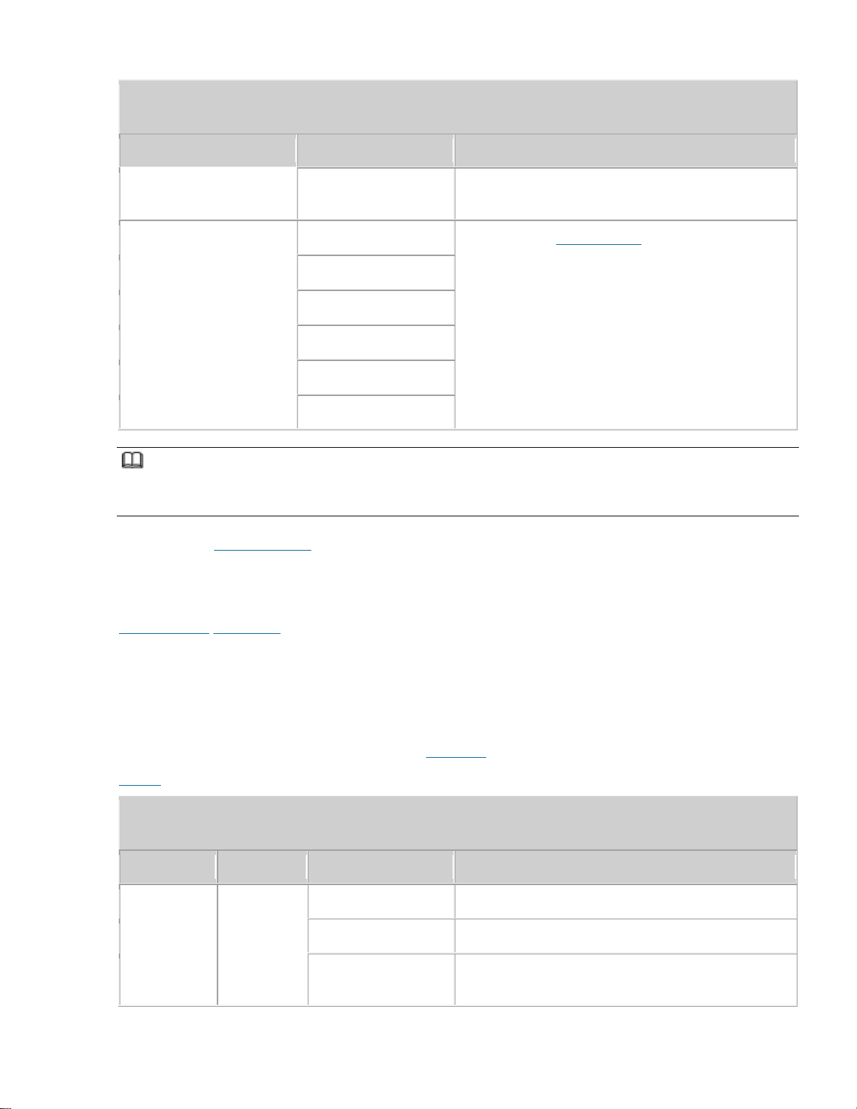
Table 1 Ports and indicators on the RRU panels
Item
Silkscreen
Remarks
RET
Communication port for the RET antenna, supporting
RET signal transmission
(3) Indicator
RUN
For details, see RRU Indicators.
ALM
ACT
VSWR
CPRI0
CPRI1
NOTE:
• The port for transmitting RET signals is determined by the software.
• Connect the CPRI0 port to the BBU by default in the single-mode scenario.
Parent Topic: RRU Introduction
Huawei Proprietary and Confidential Copyright © Huawei Technologies Co., Ltd.
Huawei Proprietary and Confidential
Copyright © Huawei Technologies Co., Ltd.
< Previous topic Next topic >
7.2.2.3.3 RRU Indicators
This section describes six indicators on an RRU. They indicate the running status of the RRU.
For detailed positions of RRU indicators, see RRU Ports.
Table 1 describes RRU indicators.
Table 1 RRU Indicators
Indicator
Color
Status
Meaning
RUN
Green
Steady on
The power input is available, but the board is faulty.
Steady off
No power input is available, or the board is faulty.
Blinking (on for 1s
and off for 1s)
The board is running properly.

Table 1 RRU Indicators
Indicator
Color
Status
Meaning
Blinking (on for
0.125s and off for
0.125s)
The board software is being loaded, or the board is
not working.
ALM
Red
Steady on
Alarms are generated, and the module must be
replaced.
Blinking (on for 1s
and off for 1s)
Alarms are generated. The alarms may be caused by
faults on the related board or ports. Therefore, you
need to locate the fault before deciding whether to
replace the module.
Steady off
No alarms are generated.
ACT
Green
Steady on
The board is working properly when TX channels are
enabled or software is being loaded to a board that is
not started.
Blinking (on for 1s
and off for 1s)
The board is running with TX channels disabled.
VSWR
Red
Steady off
No voltage standing wave ratio (VSWR) alarm is
generated.
Blinking (on for 1s
and off for 1s)
VSWR alarms are generated on the B T/R port.
Steady on
VSWR alarms are generated on the A T/R port.
Blinking (on for
0.125s and off for
0.125s)
VSWR alarms are generated on the A T/R and B T/R
ports.
CPRI0
Red and
green
Steady green
The CPRI link is running properly.
Steady red
An optical module fails to receive or transmit signals
possibly because the optical module is faulty or the
optical fiber is broken.
Blinking red (on for
1s and off for 1s)
The CPRI link is out of lock because of faults on the
mutual lock of dual-mode clock sources or
mismatched data rates on CPRI ports.
Steady off
The optical module cannot be detected or is powered
off.
CPRI1
Steady green
The CPRI link is running properly.
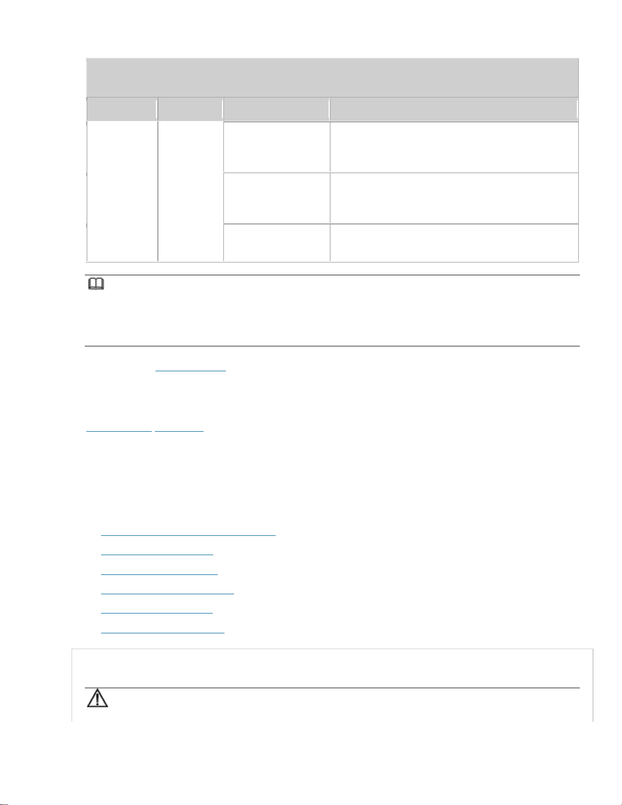
Table 1 RRU Indicators
Indicator
Color
Status
Meaning
Red and
green
Steady red
An optical module fails to receive or transmit signals
possibly because the optical module is faulty or the
optical fiber is broken.
Blinking red (on for
1s and off for 1s)
The CPRI link is out of lock because of faults on the
mutual lock of dual-mode clock sources or
mismatched data rates on CPRI ports.
Steady off
The optical module cannot be detected or is powered
off.
NOTE:
VSWR indicators on RRUs providing one or more than two TX channels have two types of status:
• Steady off: No VSWR alarm is generated.
• Steady on: VSWR alarms are generated on one or more ports.
Parent Topic: RRU Introduction
Huawei Proprietary and Confidential Copyright © Huawei Technologies Co., Ltd.
Huawei Proprietary and Confidential
Copyright © Huawei Technologies Co., Ltd.
< Previous topic Next topic >
7.2.2.3.4 Installation Scenarios
An RRU can be installed on a pole, U-steel, angle steel, wall, or IFS06. Installation scenarios must
meet heat-dissipation and waterproofing requirements of the RRU.
• Requirements for the Installation Scenarios
• Installing an RRU on a Pole
• Installing an RRU on U-Steel
• Installing an RRU on Angle Steel
• Installing an RRU on a Wall
• Installing an RRU on an IFS06
Requirements for the Installation Scenarios
NOTICE:
RRU is a professional communications equipment and cannot be installed in areas which are
accessible to people. The installation scenarios involve the related security features. For details
about specific requirements and precautions, see Safety Information.
Application scenarios:
To ensure proper heat dissipation of the RRU, the following requirements must be met:
• The RRU cannot be installed in an enclosed cabinet without a cooling system.
• The RRU cannot be installed in an enclosed camouflage box.
• The RRU cannot be installed in an enclosed equipment room without a cooling system.
• When multiple RRUs are installed in centralized mode, the minimum clearance requirements
must be met. For details about the minimum clearance requirements, see Clearance for Three or More
RRUs and Installation Spacing Between RRUs.
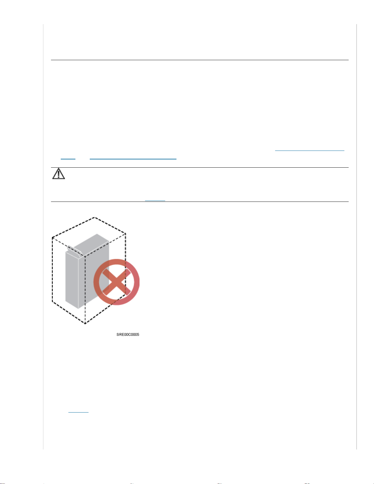
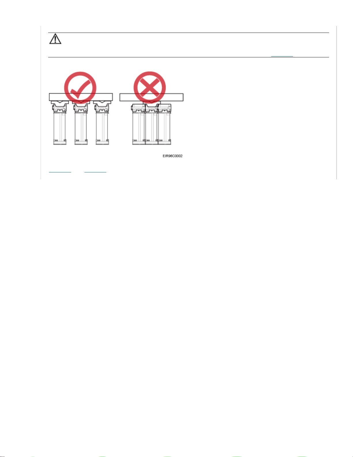
NOTICE:
If the RRU is inappropriately installed, heat dissipation of the RRU deteriorates and the RRU may
not work properly, as shown in Figure 1.
Figure 1 Inappropriately installed RRU
Installation restrictions:
• The specifications of installation supports described in this document are based only on the
exterior and dimensions of the mounting kits. Before installing equipment, assess the strength
and reliability of the installation support to determine whether it can bear the weight of the
equipment.
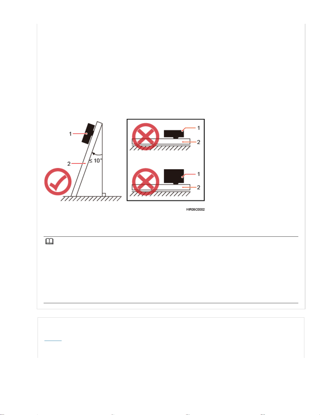
• To ensure the heat dissipation of the RRU and waterproofing of the ports at the bottom of the
RRU, the vertical deviation angle of an RRU must be less than or equal to 10 degrees, as shown
in Figure 2.
• On a tower, an RRU can be installed on a pole, angle steel, or U-steel. The side-mounted
installation mode (one side instead of the rear of an RRU is mounted on the support) is
recommended for RRUs on the main pole secured on a tower. This installation mode allows the
RRU stacked installation. When the horizontal distance between the main and auxiliary poles on
a tower is greater than or equal to 810 mm (23.62 in.), the side-mounted mode is recommended
for installing RRUs on the auxiliary pole to meet the minimum clearance requirements.
Otherwise, the standard mode is recommended for installing RRUs on the auxiliary pole.
• RRU stacked installation is not allowed in indoor scenarios.
• RRU stacked installation is allowed only when installed on one or more poles in outdoor
scenarios, and a maximum of three RRUs can be stacked installation.
• The periphery of RRU5309w external antennas should avoid metal shielding (such as wirelines
of the cable tower, metal fence, ground bar, and billboard).
Figure 2 Requirements for the vertical deviation angle of an RRU
(1) RRU
(2) Installation support (pole, U-steel, angle steel, or wall)
NOTE:
• When the operator faces the RRU whose handle and cabling cavity are on the right-hand side, the side facing the
operator is the front of the RRU, and the other side is the back of the RRU.
• Standard installation: RRU mounting kits are installed on the back of an RRU.
• Reverse installation: RRU mounting kits are installed on the front of an RRU.
• Side-mounted installation: RRU mounting kits are installed on the side face (not the side face of the maintenance
cavity) of an RRU.
• Stacked installation: Two or more RRUs are installed next to each other at the same level by stacking multiple RRU
mounting kits.
Installing an RRU on a Pole
Figure 3 shows the diameter of a pole for installing an RRU.
Figure 3 Diameter of a pole

NOTICE:
• The diameter of a pole for installing an RRU ranges from 60 mm (2.36 in.) to 114 mm (4.49 in.).
The recommended diameter is 80 mm (3.15 in.).
• The recommended thickness of the pole wall is 3.5 mm (0.14 in.) or above.
• When RRUs are installed on a pole, the side-mounted installation is recommended. A maximum
of three RRUs can be installed on a pole with the diameter ranging from 60 mm (2.36 in.) to 76
mm (2.99 in.).
• Only a pole whose diameter ranges from 76 mm (2.99 in.) to 114 mm (4.49 in.) supports more
than three RRUs.
Figure 4 shows a single RRU installed on a pole.
Figure 4 A single RRU installation on a pole
Figure 5 shows two RRUs installed on a pole.
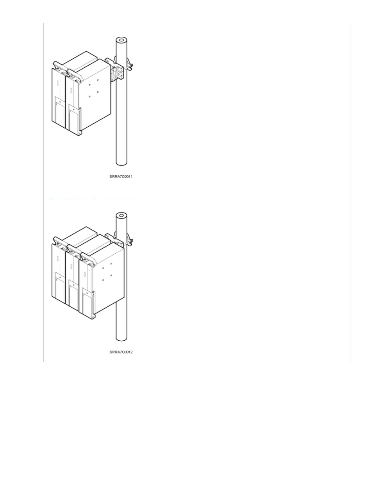
Figure 5 Two RRUs installed on a pole
Figure 6, Figure 7, and Figure 8 show multiple RRUs installed on a pole.
Figure 6 Three RRUs installed on an IFS06
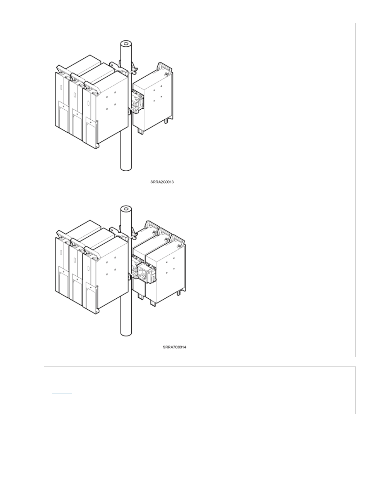
Figure 7 Four RRUs installed on a pole
Figure 8 Six RRUs installed on an IFS06
Installing an RRU on U-Steel
Figure 9 shows U-steel specifications.
Figure 9 U-steel specifications
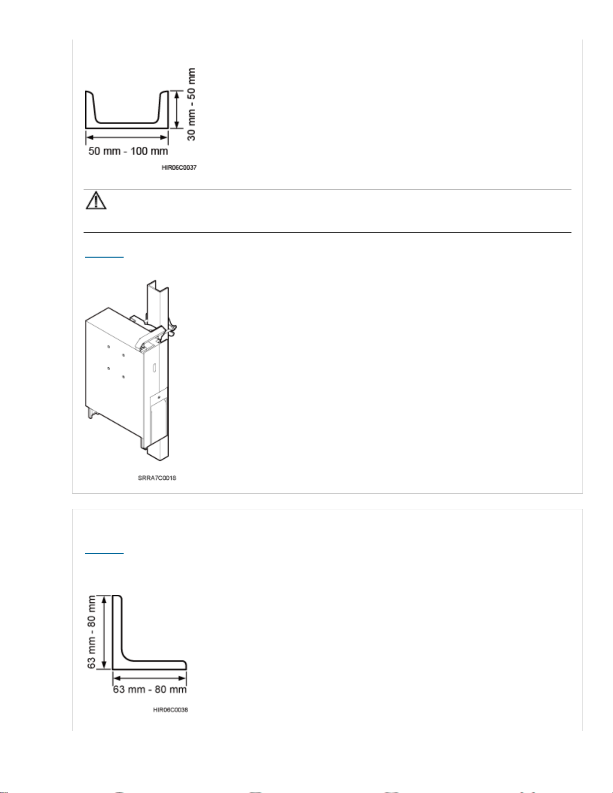
NOTICE:
U-steel supports only the standard or reverse installation of a single RRU.
Figure 10 shows an RRU installed on U-steel.
Figure 10 RRU installed on U-steel
Installing an RRU on Angle Steel
Figure 11 shows angle steel specifications.
Figure 11 Angle steel specifications
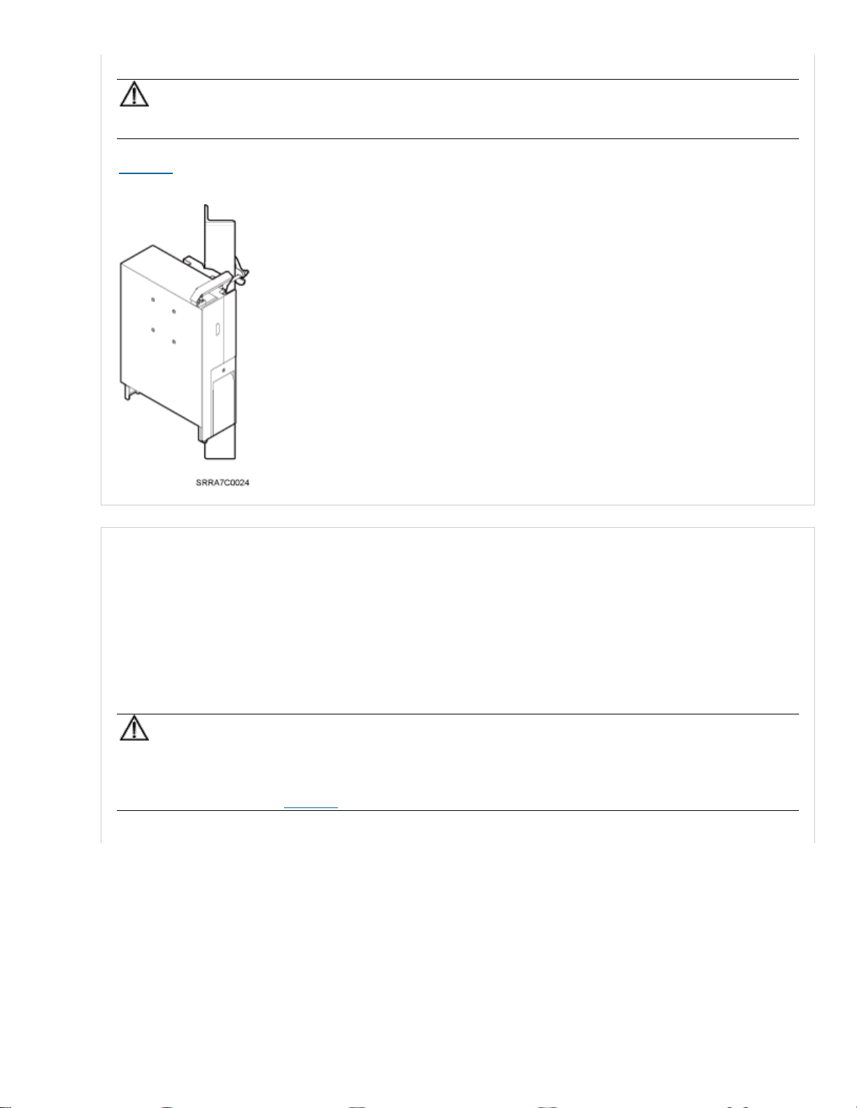
NOTICE:
Angle steel supports only the standard or reverse installation of a single RRU.
Figure 12 shows an RRU installed on angle steel.
Figure 12 RRU installed on angle steel
Installing an RRU on a Wall
The wall for installing RRUs must meet the following requirements:
• For each RRU, the wall must be able to bear a weight four times heavier than the RRU's weight
and the bolts' pulling force of 1.25 kN (281.25 lbf) vertical to the wall.
• Expansion bolts must be tightened to 30 N·m (265.52 lbf·in.) to ensure that the bolts work
properly and the wall remains intact.
NOTICE:
• The standard installation is recommended for RRUs installed on a wall.
• When RRUs are installed on a wall in side-mounted mode, RRU stacked installation is not
allowed, as shown in Figure 13.

Figure 13 Correct installation of RRUs installed on a wall in side-mounted mode
Figure 14 shows an RRU installed on a wall.
Figure 14 RRU installed on a wall
Installing an RRU on an IFS06
• The upper and lower adjustable beams on an IFS06 can be moved up and down to fit for heights
of RRUs.
• The IFS06 supports at least three RRUs when the ambient temperature is higher than or equal to
the lowest operating temperature of the RRUs and at least 5°C (41°F) lower than the highest
operating temperature of the RRUs. The IFS06 supports a maximum of six RRUs when the
ambient temperature is higher than or equal to the lowest operating temperature of the RRUs and
at least 10°C (50°F) lower than the highest operating temperature of the RRUs.
NOTE:
For details about the operating temperature of the RRUs, see section "Technical Specifications of RRUs" in Base
Station Technical Description.
NOTICE:
RRUs cannot be stacked when the RRUs are installed on an IFS06, as shown in Figure 15.
Figure 15 Correct installation of RRUs installed on an IFS06
Figure 16 and Figure 17 show RRUs installed on an IFS06.
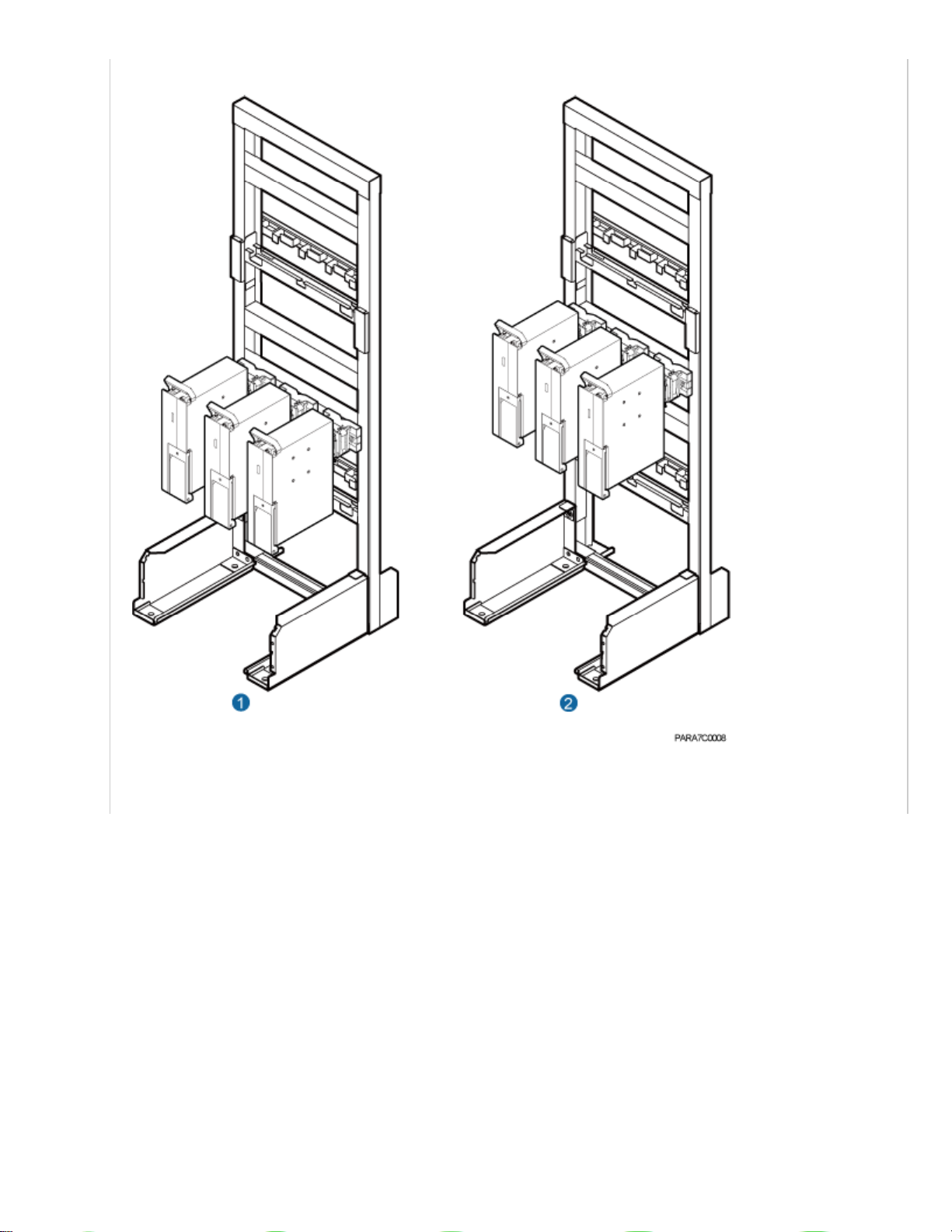
Figure 16 Three RRUs installed on an IFS06
(1) Height-restricted scenario
(2) Height-unrestricted scenario

Figure 17 Six RRUs installed on an IFS06
(1) Height-restricted scenario
(2) Height-unrestricted scenario
Parent Topic: Information About the Installation
Huawei Proprietary and Confidential Copyright © Huawei Technologies Co., Ltd.
Huawei Proprietary and Confidential
Copyright © Huawei Technologies Co., Ltd.
< Previous topic Next topic >
7.2.2.3.5 Installation Clearance Requirements
of an RRU

This section describes the requirements for the installation clearance of a single RRU and multiple
RRUs and the requirements for the installation spacing between RRUs.
Clearance for a Single RRU
This section describes the recommended and minimum clearances for a single RRU.
Clearance for Three or More RRUs
This section describes the recommended and minimum clearances for three or more RRUs.
Installation Spacing Between RRUs
This section describes the horizontal and vertical spacing between RRUs.
Parent Topic: Information About the Installation
Huawei Proprietary and Confidential Copyright © Huawei Technologies Co., Ltd.
Huawei Proprietary and Confidential
Copyright © Huawei Technologies Co., Ltd.
< Previous topic
7.2.2.3.5.1 Clearance for a Single RRU
This section describes the recommended and minimum clearances for a single RRU.
NOTICE:
If an RRU is installed on the bitumen ground, the RRU must be at least 500 mm (700 mm or more is
recommended) away from the bitumen ground. The following describes the space requirements for
installing a single RRU on the non-bitumen ground.
NOTE:
• The recommended clearances ensure normal running and provide appropriate space for operation and maintenance
(O&M). If the installation space is sufficient, leave the recommended clearances after installing the equipment.
• The minimum clearance ensures normal running and heat dissipation, but O&M activities such as checking indicator
status and opening the cabling cavity cannot be properly conducted. If the installation space is restricted, leave the
minimum clearance after installing the equipment.
• Clearance for a Single RRU in Side-Mounted Mode
• Clearance for a Single RRU in Standard or Reverse Mode
• Clearance for a Single Tower-Mounted RRU
Clearance for a Single RRU in Side-Mounted Mode
Figure 1 shows the clearance for a single RRU in side-mounted mode.
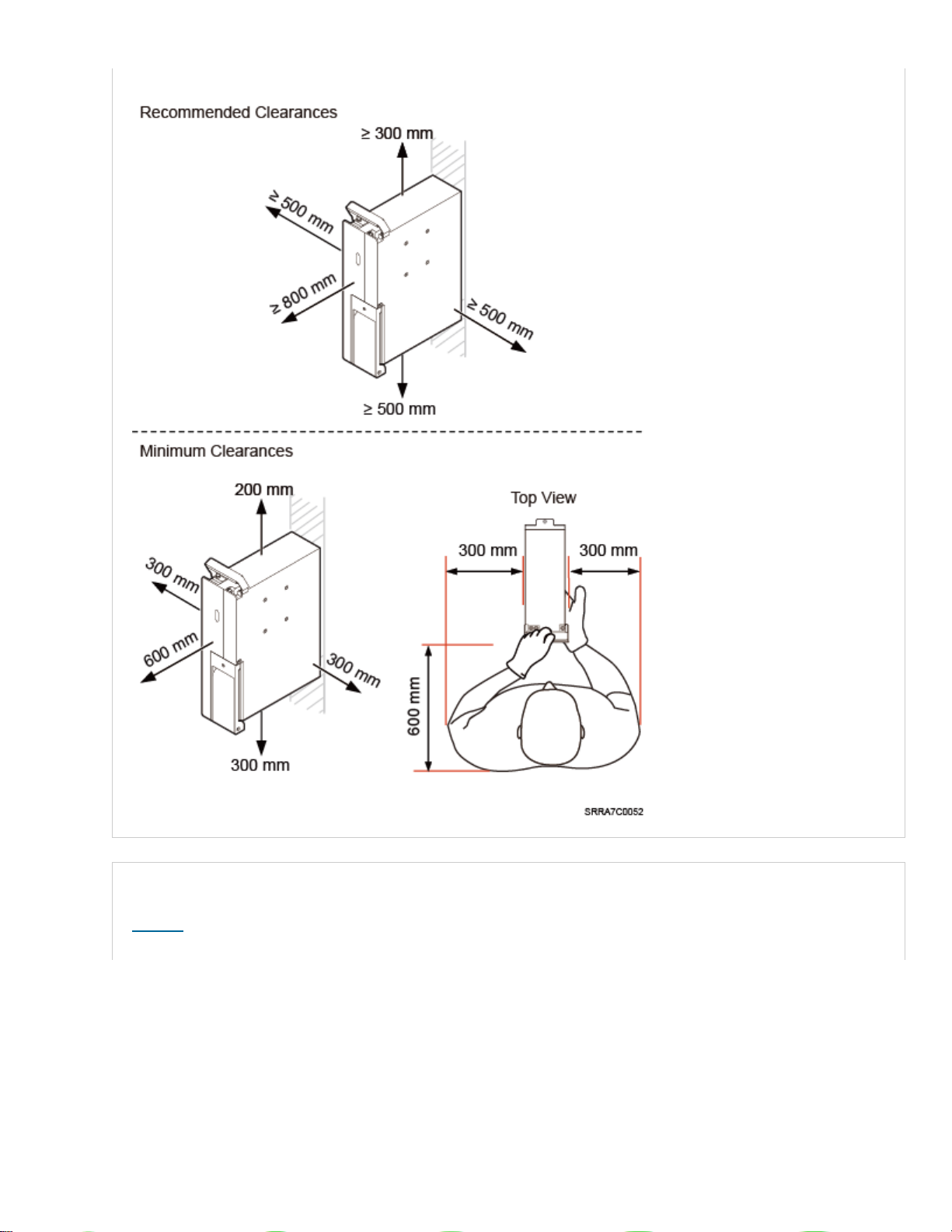
Figure 1 Clearance for a single RRU in side-mounted mode
Clearance for a Single RRU in Standard or Reverse Mode
Figure 2 shows the clearance for a single RRU in standard or reverse mode.
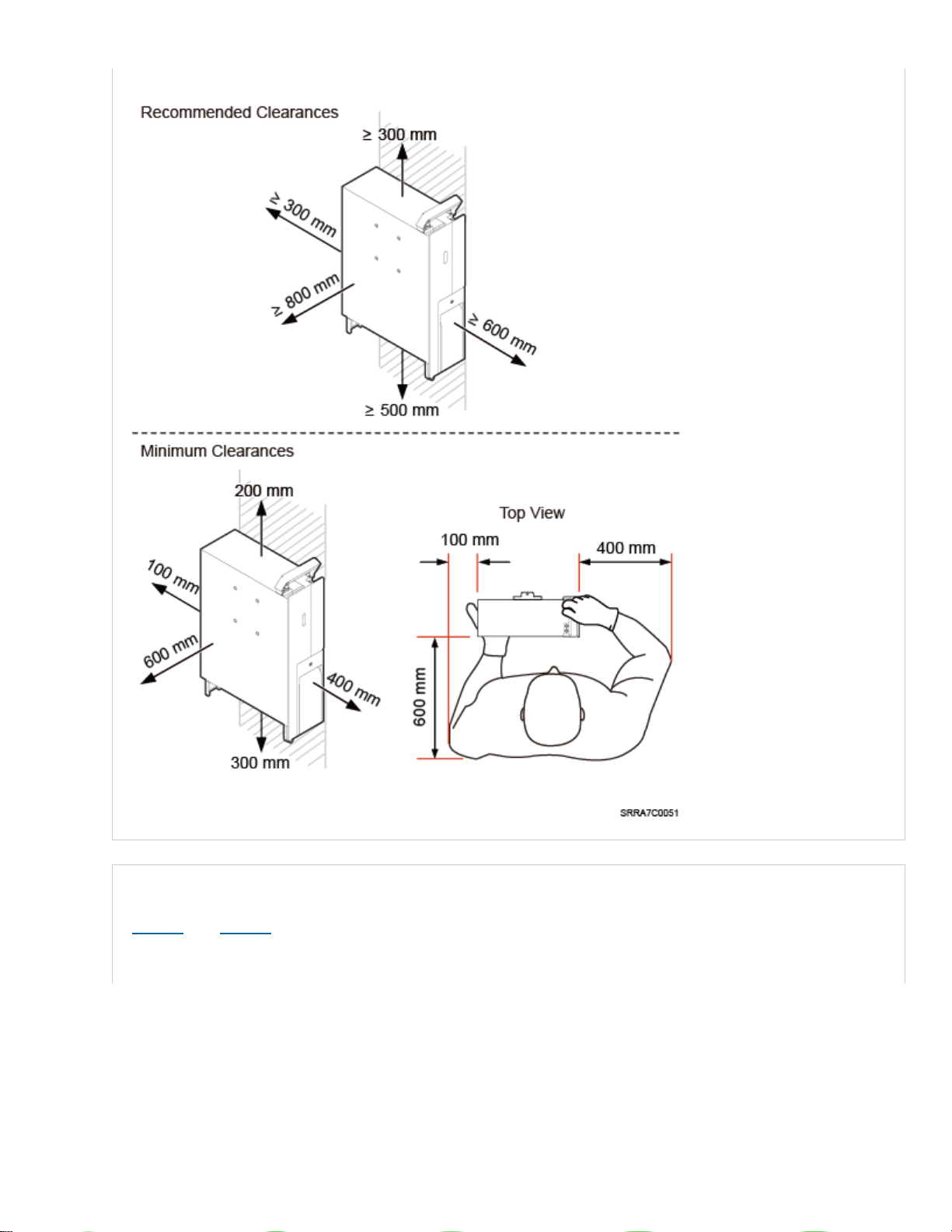
Figure 2 Clearance for a single RRU in standard or reverse mode
Clearance for a Single Tower-Mounted RRU
Figure 3 and Figure 4 show the minimum clearances for a single RRU in side-mounted mode and
standard or reverse mode on a tower.
 Loading...