


RRU3942
Installation Guide
Issue
Date
HUAWEI TECHNOLOGIES CO., LTD.

Copyright © Huawei Technologies Co., Ltd. 2011. All rights reserved.
No part of this document may be reproduced or transmitted in any form or by any means without prior written
consent of Huawei Technologies Co., Ltd.
Trademarks and Permissions
and other Huawei trademarks are trademarks of Huawei Technologies Co., Ltd.
All other trademarks and trade names mentioned in this document are the property of their respective holders.
Notice
The purchased products, services and features are stipulated by the contract made between Huawei and the
customer. All or part of the products, services and features described in this document may not be within the
purchase scope or the usage scope. Unless otherwise specified in the contract, all statements, information,
and recommendations in this document are provided "AS IS" without warranties, guarantees or representations
of any kind, either express or implied.
The information in this document is subject to change without notice. Every effort has been made in the
preparation of this document to ensure accuracy of the contents, but all statements, information, and
recommendations in this document do not constitute the warranty of any kind, express or implied.
Huawei Technologies Co., Ltd.
Address: Huawei Industrial Base
Bantian, Longgang
Shenzhen 518129
People's Republic of China
Website: http://www.huawei.com
Email: support@huawei.com
Issue () Huawei Proprietary and Confidential
Copyright © Huawei Technologies Co., Ltd.
i
RRU3942
Installation Guide About This Document
About This Document
Purpose
This document describes the process of installing a DC RRU3942 (referred to as RRU in this
document).
Product Version
The following table lists the product version related to this document.
Product Name Product Version
DBS3900 V100R004C00 and later versions
Intended Audience
This document is intended for:
Base station installation engineers
Organization
1 Changes in the RRU3942 Installation Guide
This chapter describes the changes in the RRU3942 Installation Guide.
2 Installation Preparations
This chapter describes the reference documents, tools, and instruments that must be ready before
the installation. In addition, it specifies the skills and prerequisites that installation engineers
must have.
3 Information About the Installation
Before installing an RRU, you must be familiar with its exterior, ports, installation options,
physical supports, and installation clearance requirements.
4 Unpacking the Equipment
Unpack and check the delivered equipment to ensure that all the materials are included and intact.
Issue () Huawei Proprietary and Confidential
Copyright © Huawei Technologies Co., Ltd.
ii
RRU3942
Installation Guide About This Document
5 Installation Process
The installation process involves installing an RRU and RRU cables, checking the RRU
hardware installation, and powering on the RRU.
6 Installing the RRU
This chapter describes the procedure for installing the RRU. The RRU can be installed on a pole,
U-steel, angle steel, or wall. The procedure for installing the RRU varies depending on
installation options.
7 Installing RRU Cables
This chapter describes the procedure for installing RRU cables.
8 Checking the RRU Hardware Installation
After an RRU is installed, check the hardware installation.
9 Powering On an RRU
After all the devices are installed, check the power-on status of an RRU.
Conventions
10 Appendix
This section describes the procedure for adding an easy power receptacle (pressfit type)
connector.
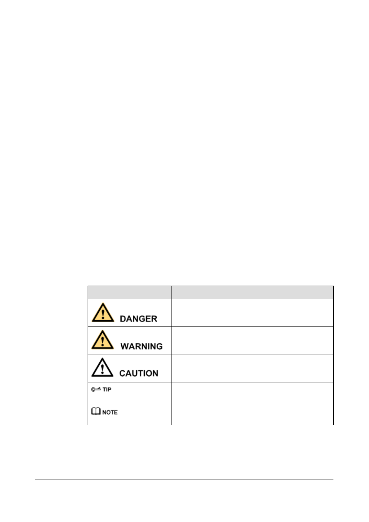
Symbol Conventions
The symbols that may be found in this document are defined as follows.
Symbol
Description
Indicates a hazard with a high level of risk, which if not
avoided, will result in death or serious injury.
Indicates a hazard with a medium or low level of risk, which
if not avoided, could result in minor or moderate injury.
Indicates a potentially hazardous situation, which if not
avoided, could result in equipment damage, data loss,
performance degradation, or unexpected results.
Indicates a tip that may help you solve a problem or save
time.
Provides additional information to emphasize or supplement
important points of the main text.
General Conventions
The general conventions that may be found in this document are defined as follows.
Issue () Huawei Proprietary and Confidential
Copyright © Huawei Technologies Co., Ltd.
iii
RRU3942
Installation Guide About This Document
Convention Description
Times New Roman Normal paragraphs are in Times New Roman.
Boldface Names of files, directories, folders, and users are in
boldface. For example, log in as user root.
Italic Book titles are in italics.
Courier New
Examples of information displayed on the screen are in
Courier New.
Command Conventions
The command conventions that may be found in this document are defined as follows.
Convention Description
Boldface The keywords of a command line are in boldface.
Italic Command arguments are in italics.
[ ] Items (keywords or arguments) in brackets [ ] are optional.
{ x | y | ... } Optional items are grouped in braces and separated by
vertical bars. One item is selected.
[ x | y | ... ] Optional items are grouped in brackets and separated by
vertical bars. One item is selected or no item is selected.
{ x | y | ... }
*
Optional items are grouped in braces and separated by
vertical bars. A minimum of one item or a maximum of all
items can be selected.
[ x | y | ... ]
*
Optional items are grouped in brackets and separated by
vertical bars. Several items or no item can be selected.
GUI Conventions
The GUI conventions that may be found in this document are defined as follows.
Convention
Description
Boldface Buttons, menus, parameters, tabs, window, and dialog titles
are in boldface. For example, click OK.
> Multi-level menus are in boldface and separated by the ">"
signs. For example, choose File > Create > Folder.
Keyboard Operations
The keyboard operations that may be found in this document are defined as follows.
Issue () Huawei Proprietary and Confidential
Copyright © Huawei Technologies Co., Ltd.
iv
RRU3942
Installation Guide About This Document
Format Description
Key Press the key. For example, press Enter and press Tab.
Key 1+Key 2 Press the keys concurrently. For example, pressing Ctrl+Alt
+A means the three keys should be pressed concurrently.
Key 1, Key 2 Press the keys in turn. For example, pressing Alt, A means
the two keys should be pressed in turn.
Mouse Operations
The mouse operations that may be found in this document are defined as follows.
Action Description
Click Select and release the primary mouse button without moving
the pointer.
Double-click Press the primary mouse button twice continuously and
quickly without moving the pointer.
Drag Press and hold the primary mouse button and move the
pointer to a certain position.
Issue () Huawei Proprietary and Confidential
Copyright © Huawei Technologies Co., Ltd.
v

RRU3942
Installation Guide Contents
Contents
About This Document.....................................................................................................................ii
1 Changes in the RRU3942 Installation Guide...........................................................................1
2 Installation Preparations..............................................................................................................2
2.1 Reference Documents.........................................................................................................................................3
2.2 Tools and Instruments........................................................................................................................................3
2.3 Skills and Requirements for Onsite Personnel...................................................................................................4
3 Information About the Installation...........................................................................................5
3.1 RRU Exterior......................................................................................................................................................6
3.2 RRU Ports...........................................................................................................................................................6
3.3 RRU Indicators...................................................................................................................................................9
3.4 Installation Options...........................................................................................................................................10
3.5 Installation Clearance Requirements of an RRU..............................................................................................15
3.5.1 Installation Clearance for a Single RRU.................................................................................................15
3.5.2 Installation Clearance for Multiple RRUs...............................................................................................17
3.5.3 Installation Spacing Between RRUs........................................................................................................20
4 Unpacking the Equipment.........................................................................................................24
5 Installation Process.....................................................................................................................26
6 Installing the RRU.......................................................................................................................27
6.1 Mounting Kits for an RRU...............................................................................................................................29
6.2 Installing the RRU on a Pole............................................................................................................................29
6.2.1 Installing a Single RRU...........................................................................................................................32
6.2.2 Installing Two RRUs...............................................................................................................................34
6.2.3 Installing Multiple RRUs.........................................................................................................................37
6.3 Installing the RRU on U-steel..........................................................................................................................40
6.4 Installing the RRU on Angle Steel...................................................................................................................44
6.5 Installing the RRU on a Wall...........................................................................................................................47
6.6 Hoisting an RRU onto a Tower........................................................................................................................51
7 Installing RRU Cables................................................................................................................55
7.1 Cabling Requirements......................................................................................................................................57
7.2 Cable Connections............................................................................................................................................62
Issue () Huawei Proprietary and Confidential
Copyright © Huawei Technologies Co., Ltd.
vi

RRU3942
Installation Guide Contents
7.3 Installation Process...........................................................................................................................................65
7.4 RRU Cable List................................................................................................................................................66
7.5 Installing an RRU PGND Cable.......................................................................................................................68
7.6 Installing an RRU RF Jumper..........................................................................................................................70
7.7 Installing an Inter-RRU RF Cable....................................................................................................................72
7.8 Installing an RRU AISG Multi-Wire Cable and AISG Extension Cable.........................................................73
7.9 Opening the Cover Plate of an RRU Cabling Cavity.......................................................................................75
7.10 Installing an RRU power cable.......................................................................................................................77
7.11 Installing a CPRI Fiber Optic Cable...............................................................................................................79
7.12 Installing an RRU Alarm Cable......................................................................................................................81
7.13 Closing the Cover Plate of an RRU Cabling Cavity......................................................................................82
8 Checking the RRU Hardware Installation..............................................................................84
9 Powering On an RRU.................................................................................................................85
10 Appendix.....................................................................................................................................86
10.1 Adding an Easy Power Receptacle (Pressfit Type) Connector to the RRU Power Cable on the RRU Side
................................................................................................................................................................................87
Issue () Huawei Proprietary and Confidential
Copyright © Huawei Technologies Co., Ltd.
vii
RRU3942
Installation Guide 1 Changes in the RRU3942 Installation Guide
1 Changes in the RRU3942 Installation Guide
This chapter describes the changes in the RRU3942 Installation Guide.
02()
01 (2011-09-30)
This is the second official release.
Compared with issue 01 (2011-09-30), this issue includes the following new information:
l Hoisting an RRU and Related Cables onto a Tower
l Hoisting Fiber Optic Cables onto a Tower
l Hoisting Power Cables onto a Tower
Compared with issue 01 (2011-09-30), this issue includes the following changes:
Topic
4 Unpacking the Equipment Added the requirements for powering on the
7.1 Cabling Requirements Optimized cabling requirements.
Compared with issue 01 (2011-09-30), no information is deleted from this issue.
This is the first official release.
Change Description
cabinet and module.
Issue () Huawei Proprietary and Confidential
Copyright © Huawei Technologies Co., Ltd.
1

RRU3942
Installation Guide 2 Installation Preparations
2 Installation Preparations
About This Chapter
This chapter describes the reference documents, tools, and instruments that must be ready before
the installation. In addition, it specifies the skills and prerequisites that installation engineers
must have.
2.1 Reference Documents
Before the installation, you must be familiar with reference documents.
2.2 Tools and Instruments
All tools and instruments required for RRU installation must be ready before the installation.
2.3 Skills and Requirements for Onsite Personnel
Onsite personnel must be qualified and trained. Before performing any operation, onsite
personnel must be familiar with correct operation methods and safety precautions.
Issue () Huawei Proprietary and Confidential
Copyright © Huawei Technologies Co., Ltd.
2
RRU3942
Installation Guide 2 Installation Preparations
2.1 Reference Documents
Before the installation, you must be familiar with reference documents.
The following reference documents are required during RRU installation:
l RRU3942 Hardware Description
l RRU3942 Hardware Maintenance Guide
l DBS3900 Installation Guide
l OCB User Guide
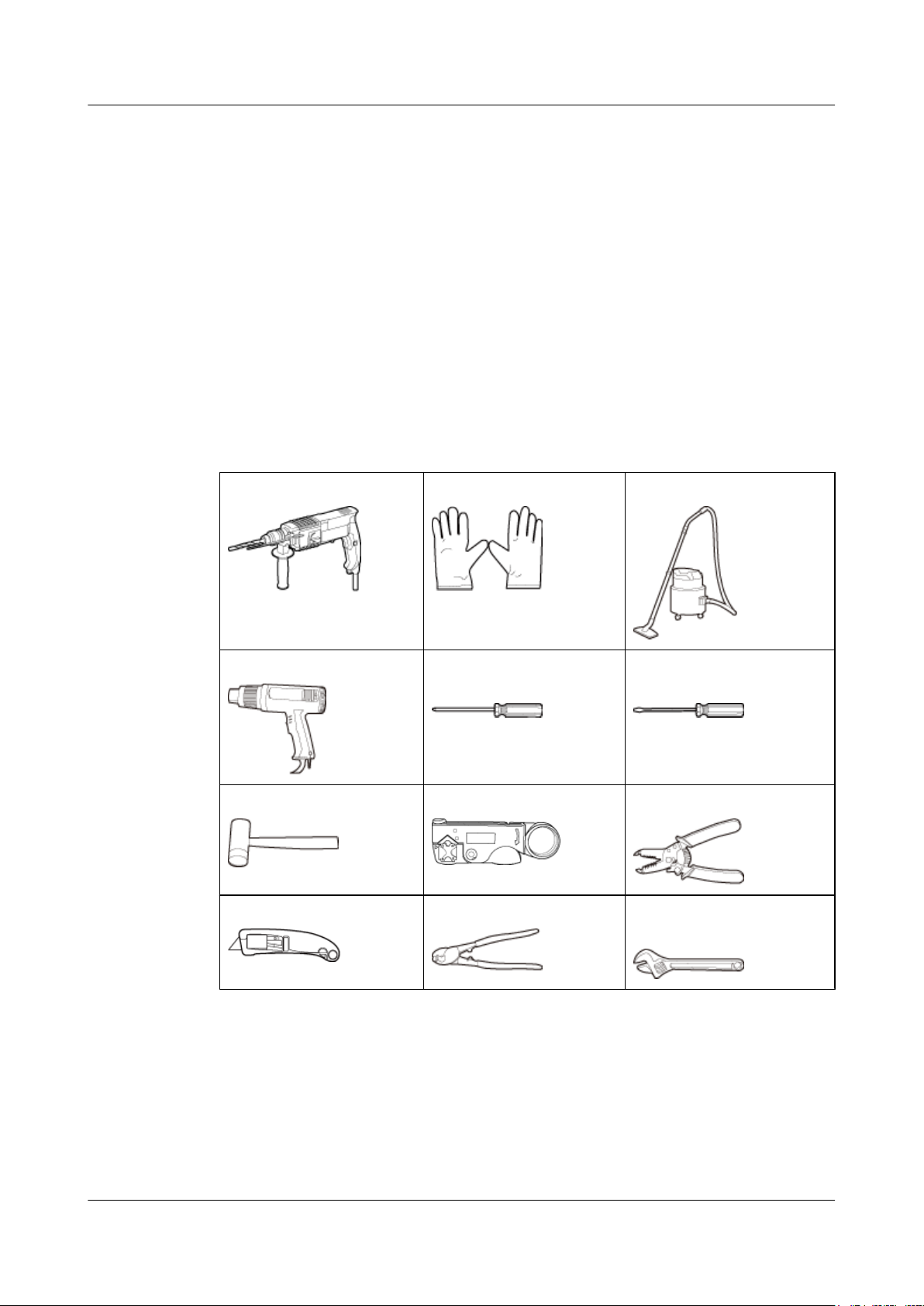
2.2 Tools and Instruments
All tools and instruments required for RRU installation must be ready before the installation.
Hammer drill (a φ 14 bit)
Heat gun Phillips screwdriver (M3 to
Rubber mallet COAX crimping tool Wire stripper
Utility knife Cable cutter Adjustable wrench (capacity
ESD gloves Vacuum cleaner
Flat-head screwdriver (M3 to
M6)
M6)
≥ 32 mm [1.26 in.])
Issue () Huawei Proprietary and Confidential
Copyright © Huawei Technologies Co., Ltd.
3
RRU3942
Installation Guide 2 Installation Preparations
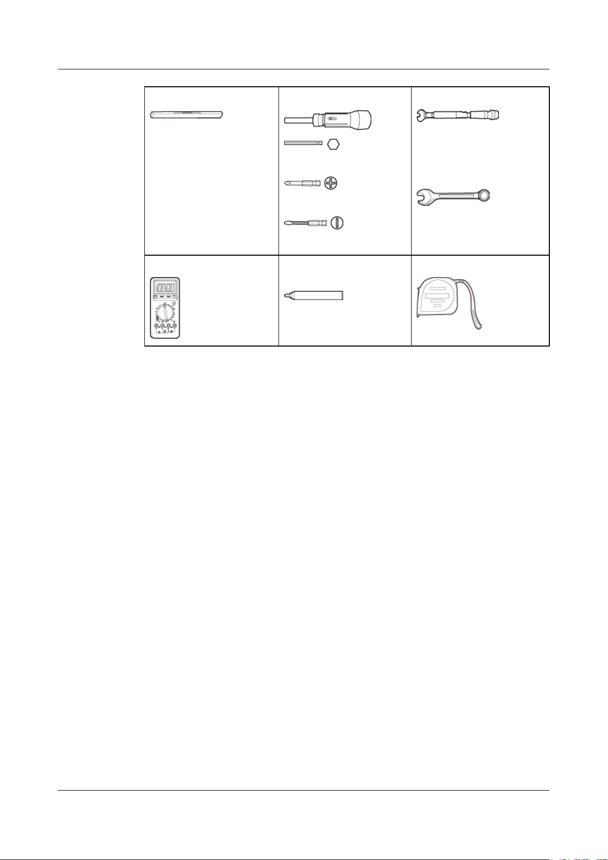
Level Torque screwdriver
5 mm
(M3 to M6)
(M3 to M6)
Multimeter
Marker (diameter ≤ 10 mm
[0.39 in.])
Torque wrench
Capacity: 17 mm [0.67 in.], 21
mm [0.82 in.], and 32 mm
[1.26 in.]
Combination wrench
Capacity: 17 mm [0.67 in.], 21
mm [0.82 in.], and 32 mm
[1.26 in.]
Measuring tape
2.3 Skills and Requirements for Onsite Personnel
Onsite personnel must be qualified and trained. Before performing any operation, onsite
personnel must be familiar with correct operation methods and safety precautions.
Before the installation, pay attention to the following items:
l The customer's technical engineers must be trained by Huawei and be familiar with the
proper installation and operation methods.
l The number of onsite personnel depends on the engineering schedule and installation
environment. Generally, only three to five onsite personnel are necessary.
Issue () Huawei Proprietary and Confidential
Copyright © Huawei Technologies Co., Ltd.
4

RRU3942
Installation Guide 3 Information About the Installation
3 Information About the Installation
About This Chapter
Before installing an RRU, you must be familiar with its exterior, ports, installation options,
physical supports, and installation clearance requirements.
3.1 RRU Exterior
This section describes the exterior and dimensions of an RRU.
3.2 RRU Ports
This section describes RRU ports positioned on the RRU panels. An RRU has a bottom panel,
cabling cavity panel, and indicator panel.
3.3 RRU Indicators
This section describes six indicators on an RRU. They indicate the running status.
3.4 Installation Options
This section describes RRU installation options. An RRU can be installed on a pole, U-steel,
angle steel, or wall.
3.5 Installation Clearance Requirements of an RRU
This section describes the requirements for the installation clearance of a single RRU and
multiple RRUs and the requirements for the installation spacing between RRUs.
Issue () Huawei Proprietary and Confidential
Copyright © Huawei Technologies Co., Ltd.
5
RRU3942
Installation Guide 3 Information About the Installation
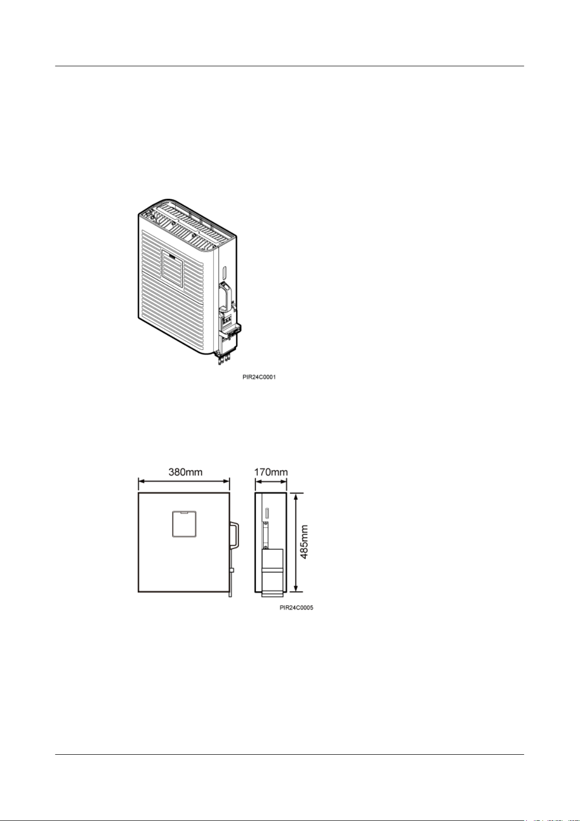
3.1 RRU Exterior
This section describes the exterior and dimensions of an RRU.
Figure 3-1 shows an RRU.
Figure 3-1 RRU exterior
Figure 3-2 shows RRU dimensions.
Figure 3-2 RRU dimensions
3.2 RRU Ports
This section describes RRU ports positioned on the RRU panels. An RRU has a bottom panel,
cabling cavity panel, and indicator panel.
Figure 3-3 shows RRU ports on the panels.
Issue () Huawei Proprietary and Confidential
Copyright © Huawei Technologies Co., Ltd.
6
RRU3942
Installation Guide 3 Information About the Installation
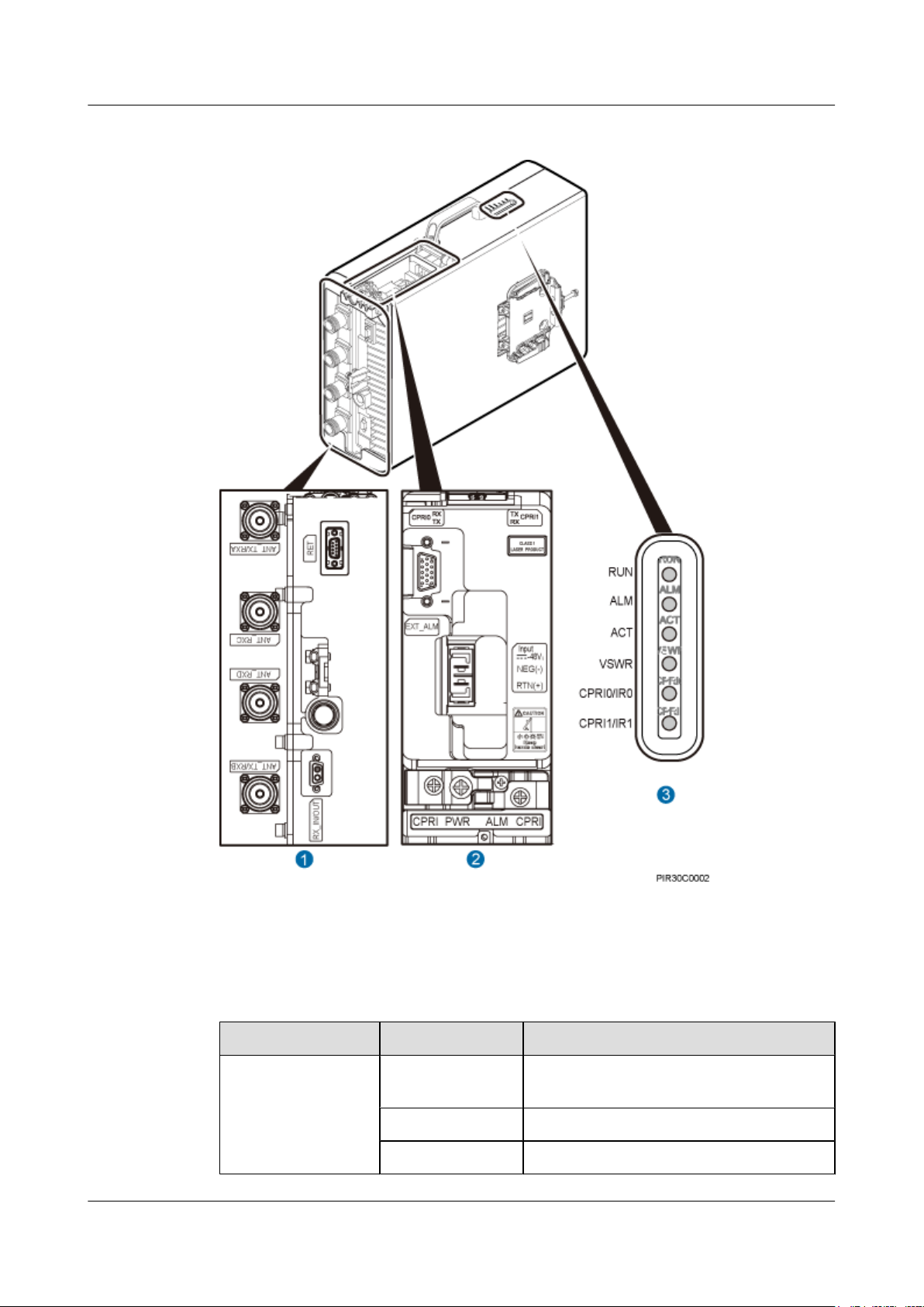
Figure 3-3 RRU ports on the panels
Table 3-1 describes RRU ports and indicators on the panels.
Table 3-1 RRU ports and indicators on the panels
Item
Label Description
(1) Ports at the bottom ANT_TX/RXA TX/RX port A, supporting RET signal
transmission
ANT_RXC RX port C
ANT_RXD Port RX port D
Issue () Huawei Proprietary and Confidential
Copyright © Huawei Technologies Co., Ltd.
7
RRU3942
Installation Guide 3 Information About the Installation
Item Label Description
ANT_TX/RXB TX/RX port B
RX_IN/OUT Port for the inter-RRU RF cable
RET Communication port for the RET antenna,
supporting RET signal transmission
(2) Ports in the cabling
RTN(+) Power supply socket
cavity
NEG(-)
CPRI0 Optical/electrical port 0
CPRI1 Optical/electrical port 1
EXT_ALM Port for alarm reporting
(3) Indicators RUN For details, see 3.3 RRU Indicators.
ALM
ACT
VSWR
CPRI0/IR0
CPRI1/IR1
NOTE
The port for transmitting RET signals is determined by the software.
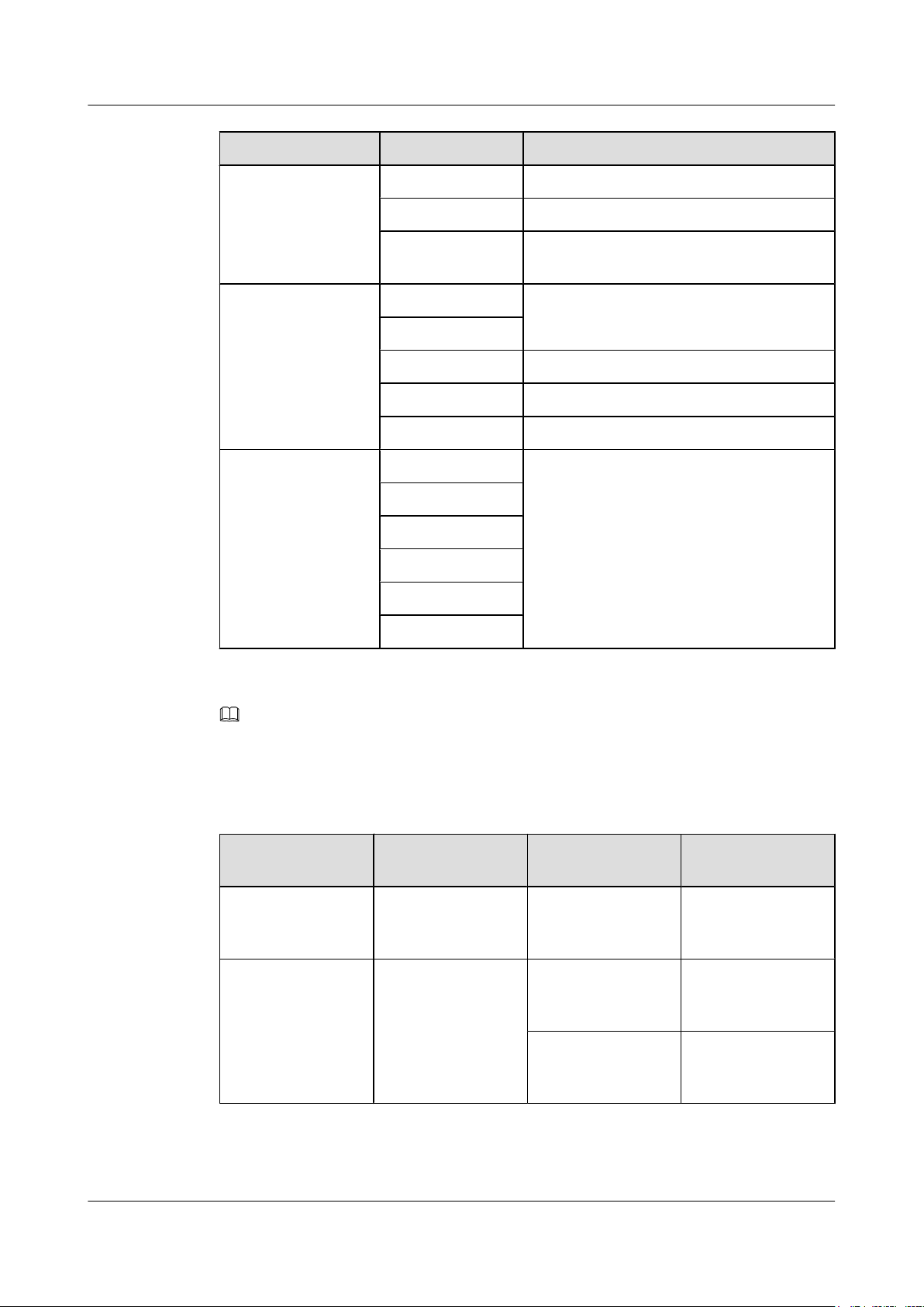
Table 3-2 describes how to use RF ports.
Table 3-2 Method of using RF ports
Product Version
TX/RX Channel Number of Used
RF Ports
MBTS V100R004 2T2R 2 ANT_TX/RXA is
Versions later than
One 1T2R 2 ANT_TX/RXA is
MBTS V100R004
2 ANT_TX/RXB is
Issue () Huawei Proprietary and Confidential
Copyright © Huawei Technologies Co., Ltd.
Method
used with ANT_TX/
RXB.
used with
ANT_RXC.
used with
ANT_RXD.
8
RRU3942
Installation Guide 3 Information About the Installation
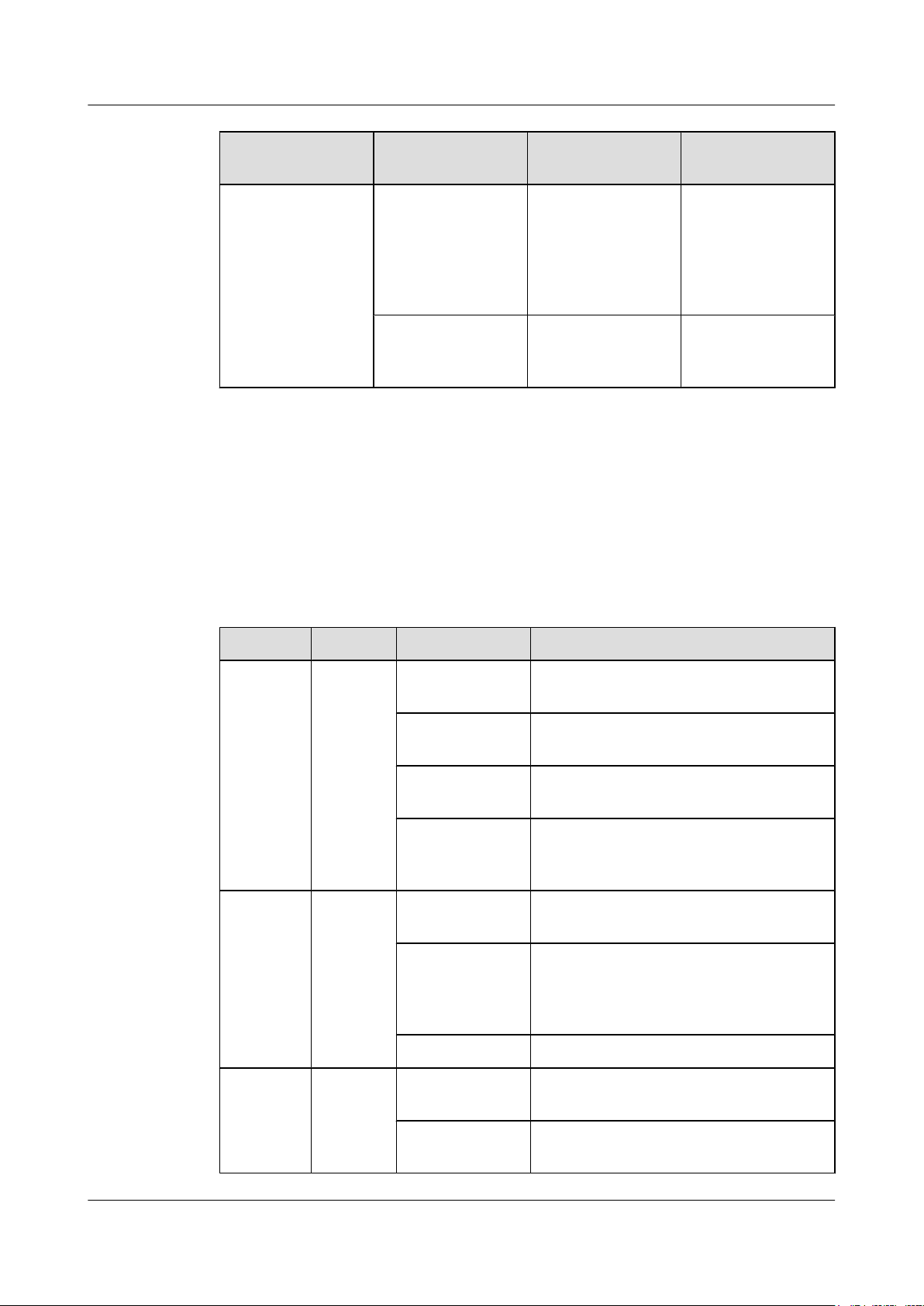
Product Version TX/RX Channel Number of Used
3.3 RRU Indicators
This section describes six indicators on an RRU. They indicate the running status.
For detailed positions of RRU indicators, see 3.2 RRU Ports.
Table 3-3 describes RRU indicators.
Method
RF Ports
Two 1T2R 4 ANT_TX/RXA is
used with
ANT_RXC, and
ANT_TX/RXB is
used with
ANT_RXD.
2T2R 2 ANT_TX/RXA is
used with ANT_TX/
RXB.
Table 3-3 RRU indicators
Label
RUN Green On There is power supply, but the module is
ALM Red On Alarms are generated, and the module must
Color Status Description
faulty.
Off There is no power supply, or the module is
faulty.
Blinking (on for
1s and off for 1s)
Blinking (on for
0.125s and off for
0.125s)
Blinking (on for
1s and off for 1s)
Off No alarm is generated.
The module is working properly.
Software is being loaded to the module, or
the module is not started.
be replaced.
Alarms are generated. The alarms may be
caused by the faults on the related boards or
ports. Therefore, the necessity for module
replacement is uncertain.
ACT Green On The module is working properly with TX
channels enabled.
Blinking (on for
1s and off for 1s)
Issue () Huawei Proprietary and Confidential
Copyright © Huawei Technologies Co., Ltd.
The module is working properly with TX
channels disabled.
9
RRU3942
Installation Guide 3 Information About the Installation
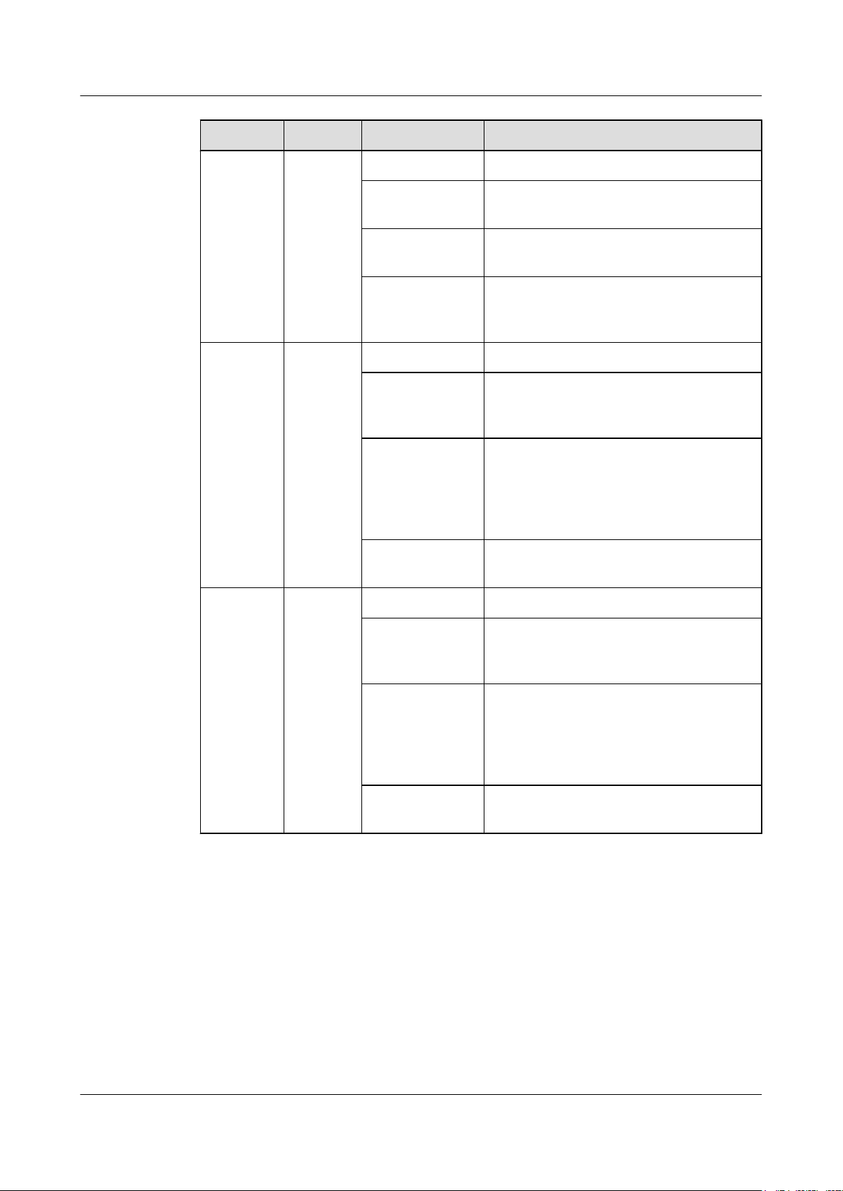
Label Color Status Description
VSWR Red Off No VSWR alarm is generated.
CPRI0/IR0 Red and
green
CPRI1/IR1 Red and
green
Blinking (on for
1s and off for 1s)
On VSWR alarms are generated on the
Blinking (on for
0.125s and off for
0.125s)
Steady green The CPRI link is available.
Steady red An optical module fails to transmit or receive
Blinking red (on
for 1s and off for
1s)
Off The SFP module is not properly installed, or
Steady green The CPRI link is available.
Steady red An optical module fails to transmit or receive
VSWR alarms are generated on the
ANT_TX/RXB port.
ANT_TX/RXA port.
VSWR alarms are generated on the
ANT_TX/RXA and ANT_TX/RXB ports.
signals because the optical module is faulty
or the fiber optic cable is broken.
The CPRI link is out of lock because of
mutual lock of dual-mode clock sources or
mismatched data rates over CPRI ports (you
are advised to check the system configuration
to identify the fault).
the optical module is powered off.
signals because the optical module is faulty
or the fiber optic cable is broken.
Blinking red (on
for 1s and off for
1s)
Off The SFP module is not properly installed, or
The CPRI link is out of lock because of
mutual lock of dual-mode clock sources or
mismatched data rates over CPRI ports (you
are advised to check the system configuration
to identify the fault).
the optical module is powered off.
3.4 Installation Options
This section describes RRU installation options. An RRU can be installed on a pole, U-steel,
angle steel, or wall.
Installing an RRU on a Pole
Figure 3-4 shows the diameter of pole for installing an AAU3801.
Issue () Huawei Proprietary and Confidential
Copyright © Huawei Technologies Co., Ltd.
10
RRU3942
Installation Guide 3 Information About the Installation
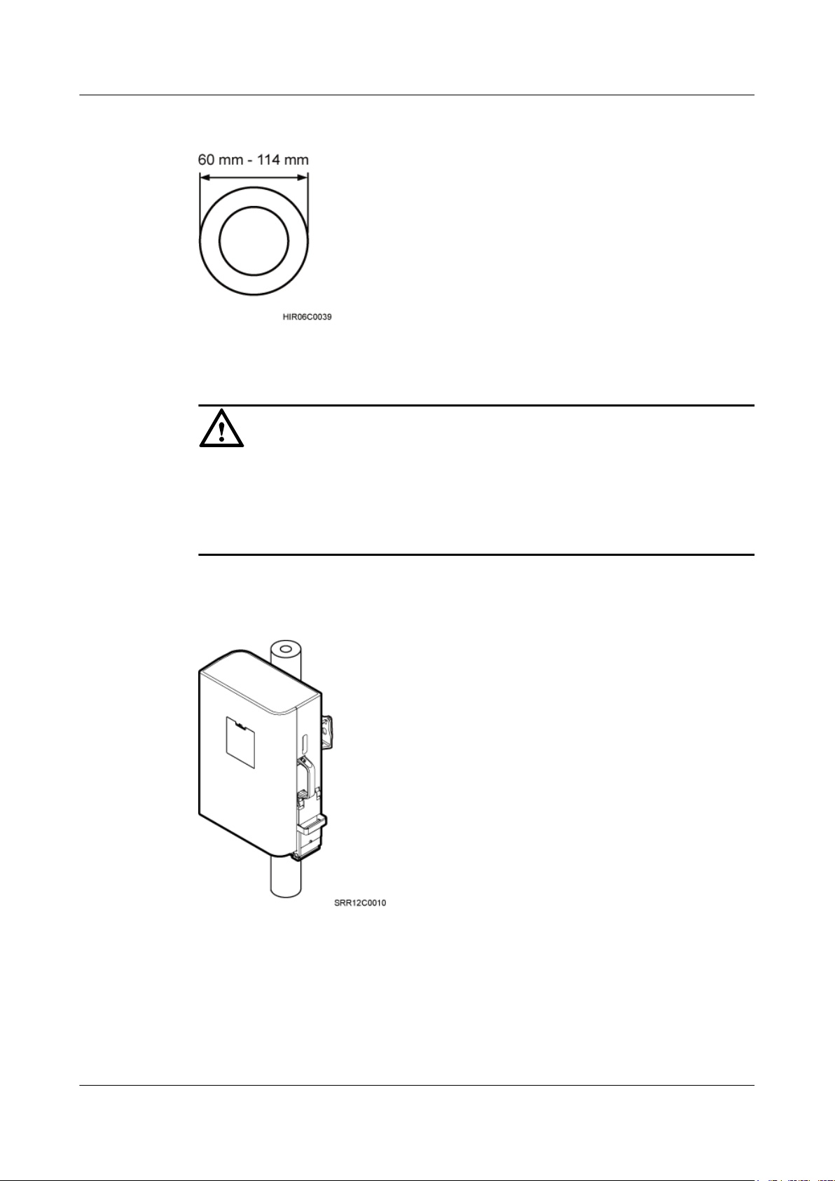
Figure 3-4 Diameter of a pole
CAUTION
l The diameter of a pole for installing an RRU ranges from 60 mm (2.36 in.) to 114 mm (4.49
in.). The recommended diameter is 80 mm (3.15 in.).
l If the diameter of a pole ranges from 60 mm (2.36 in.) to 76 mm (2.99 in.), a maximum of
two RRUs can be installed on the pole and the side-mounted installation is not recommended.
Figure 3-5 shows an RRU installed on a pole.
Figure 3-5 RRU installed on a pole
Installing an RRU on U-steel
Figure 3-6 shows U-steel specifications.
Issue () Huawei Proprietary and Confidential
Copyright © Huawei Technologies Co., Ltd.
11
RRU3942
Installation Guide 3 Information About the Installation
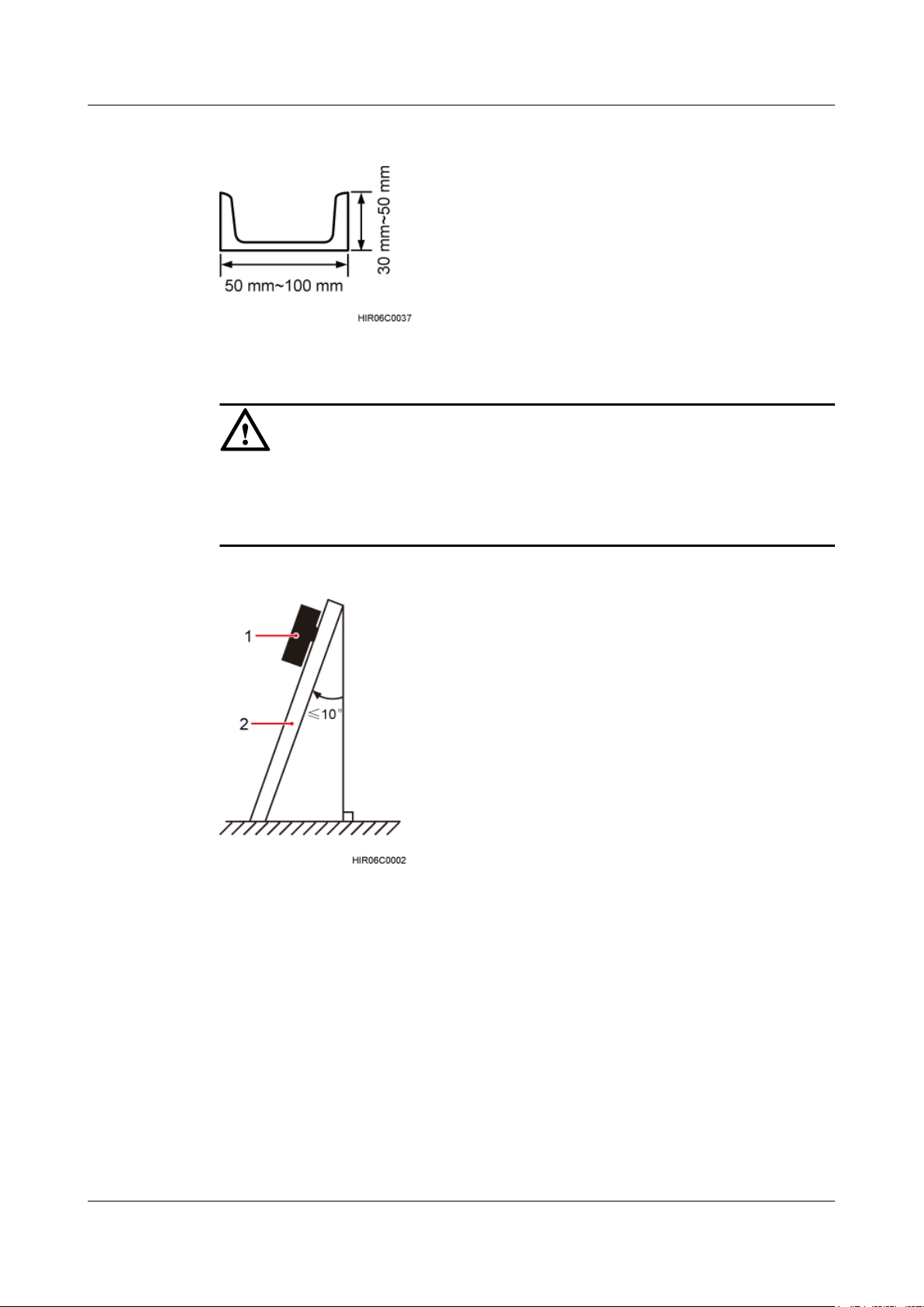
Figure 3-6 U-steel specifications
CAUTION
l It is recommended that only one RRU be installed on U-steel.
l The vertical deviation angle of U-steel must be less than or equal to 10 degrees, as shown in
Figure 3-7.
Figure 3-7 Requirements for the vertical deviation angle of U-steel or angle steel
(1) RRU
(2) U-steel or angle steel
Figure 3-8 shows an RRU installed on U-steel.
Issue () Huawei Proprietary and Confidential
Copyright © Huawei Technologies Co., Ltd.
12
RRU3942
Installation Guide 3 Information About the Installation
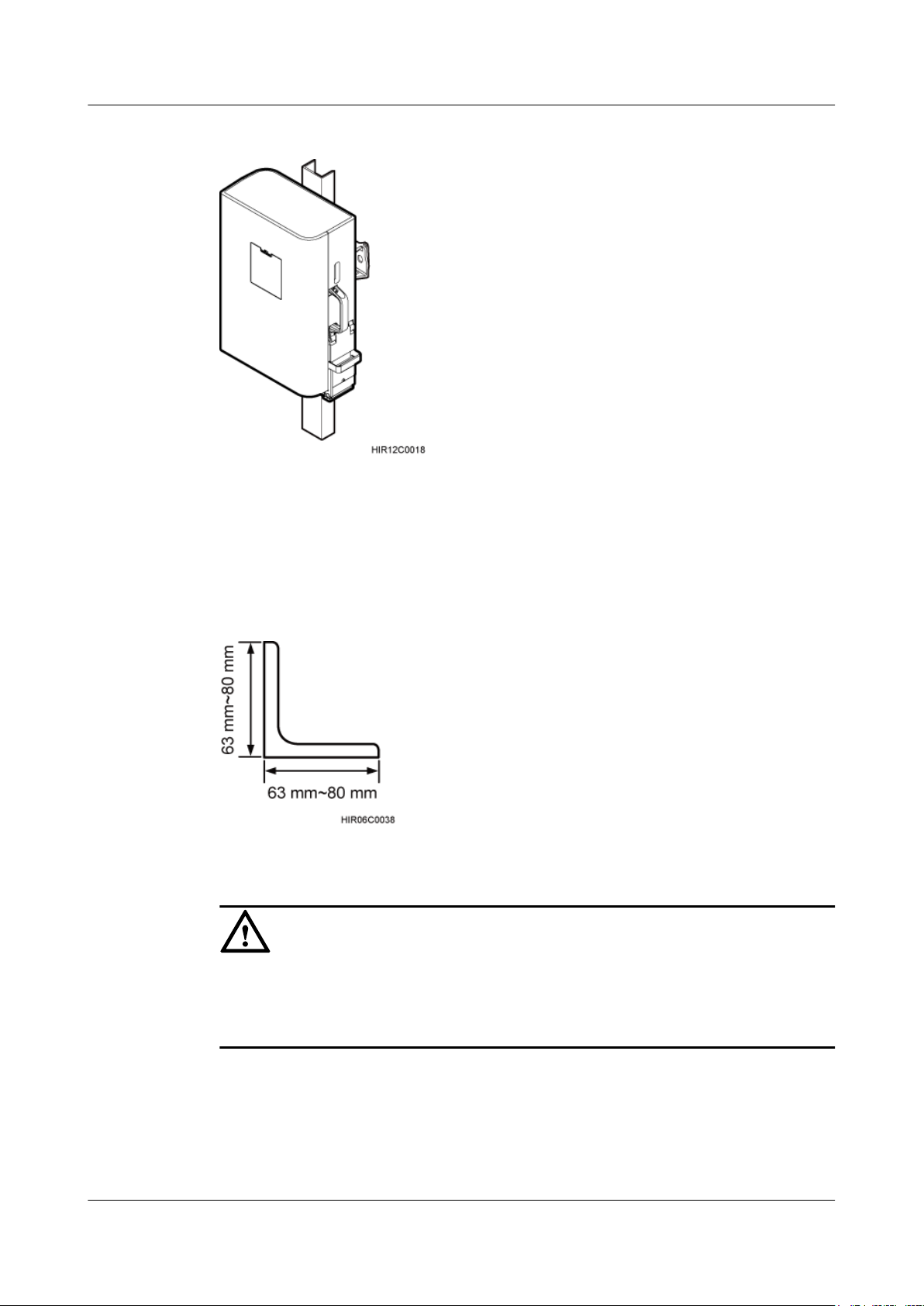
Figure 3-8 RRU installed on U-steel
Installing an RRU on Angle Steel
Figure 3-9 shows angle steel specifications.
Figure 3-9 Angle steel specifications
CAUTION
l It is recommended that only one RRU be installed on angle steel.
l The vertical deviation angle of angle steel must be less than or equal to 10 degrees, as shown
in Figure 3-7.
Figure 3-10 shows an RRU installed on angle steel.
Issue () Huawei Proprietary and Confidential
Copyright © Huawei Technologies Co., Ltd.
13
RRU3942
Installation Guide 3 Information About the Installation
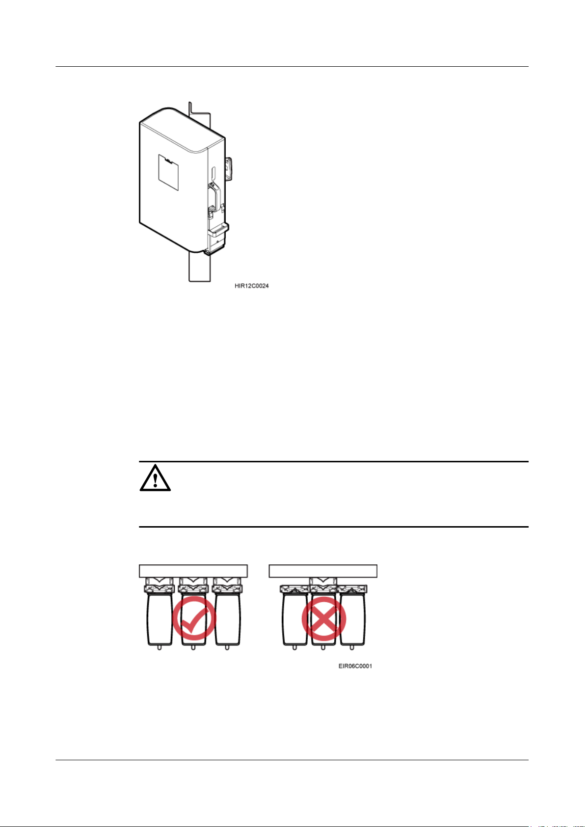
Figure 3-10 RRU installed on angle steel
Installing an RRU on a Wall
The wall on which RRUs are installed must meet the following requirements:
l When a single RRU is installed, the wall has a capacity of bearing at least four times the
weight of the RRU.
l Expansion bolts must be tightened to 30 N·m (265.52 lbf·in.) to ensure the bolts work
properly and the wall remains intact without cracks in it.
CAUTION
The brackets cannot be combined when RRUs are installed on a wall, as shown in Figure
3-11.
Figure 3-11 Correct placement of brackets
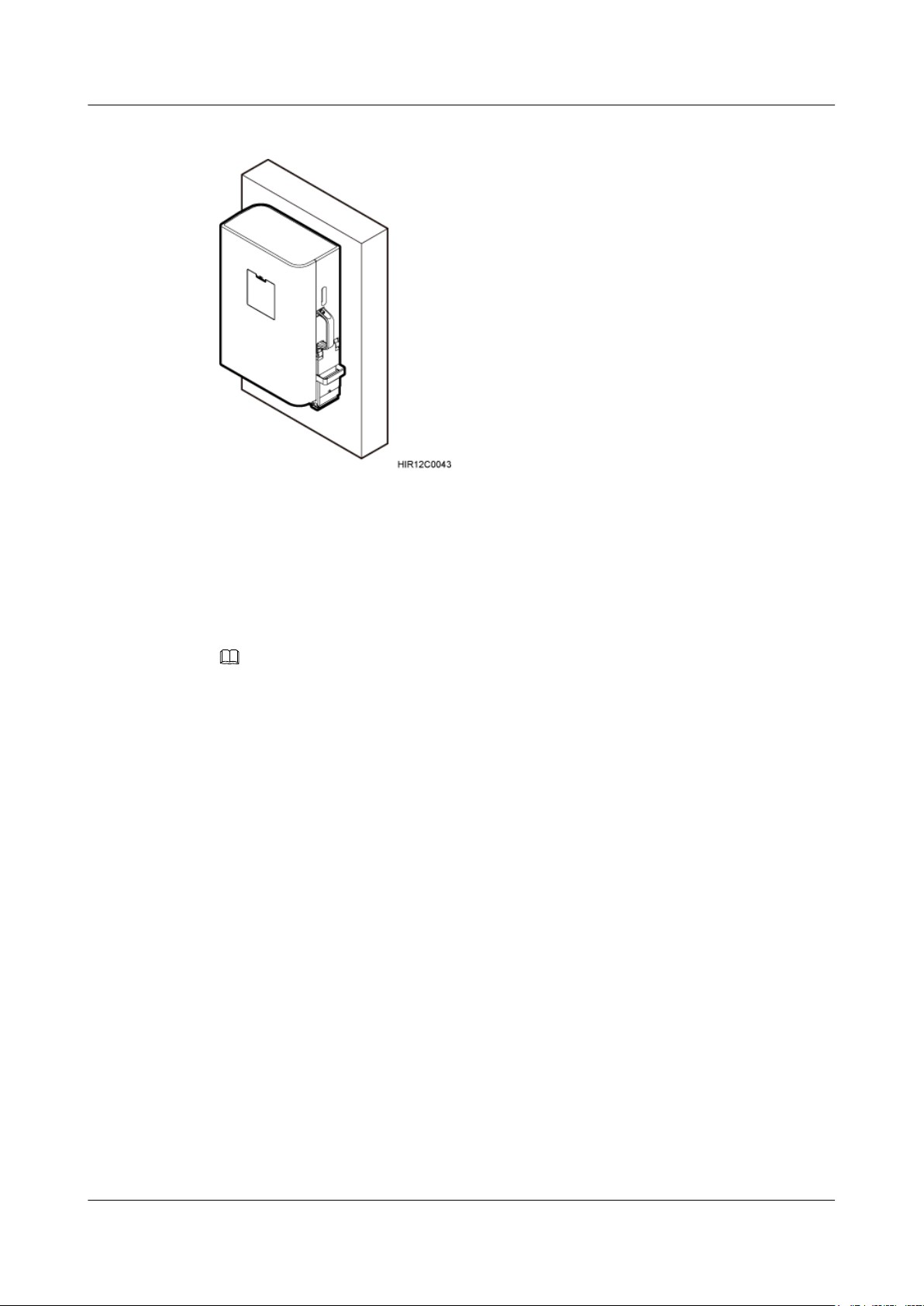
Figure 3-12 shows an RRU installed on a wall.
Issue () Huawei Proprietary and Confidential
Copyright © Huawei Technologies Co., Ltd.
14
RRU3942
Installation Guide 3 Information About the Installation
Figure 3-12 RRU installed on a wall
3.5 Installation Clearance Requirements of an RRU
This section describes the requirements for the installation clearance of a single RRU and
multiple RRUs and the requirements for the installation spacing between RRUs.
NOTE
The recommended installation clearance ensures normal running and provides an appropriate space for
Operation and Maintenance (O&M). If there is sufficient space, leave the recommended installation
clearance.
The minimum installation clearance ensures normal running and heat dissipation, but OM activities such
as checking indicator status and opening the maintenance cavity cannot be properly conducted. If the
installation space is restricted, leave the minimum installation clearance.
3.5.1 Installation Clearance for a Single RRU
This section describes the recommended and minimum installation clearance for a single RRU.
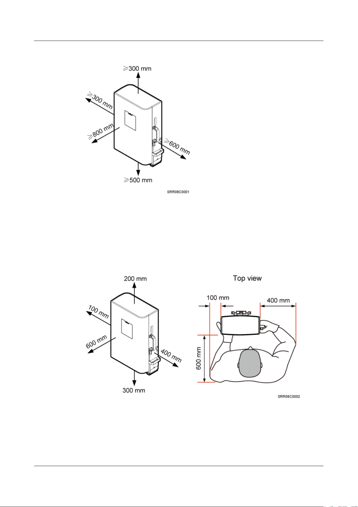
Recommended Installation Clearance for a Single RRU
Figure 3-13 shows the recommended installation clearance for a single RRU.
Issue () Huawei Proprietary and Confidential
Copyright © Huawei Technologies Co., Ltd.
15
RRU3942
Installation Guide 3 Information About the Installation
Figure 3-13 Recommended installation clearance for a single RRU
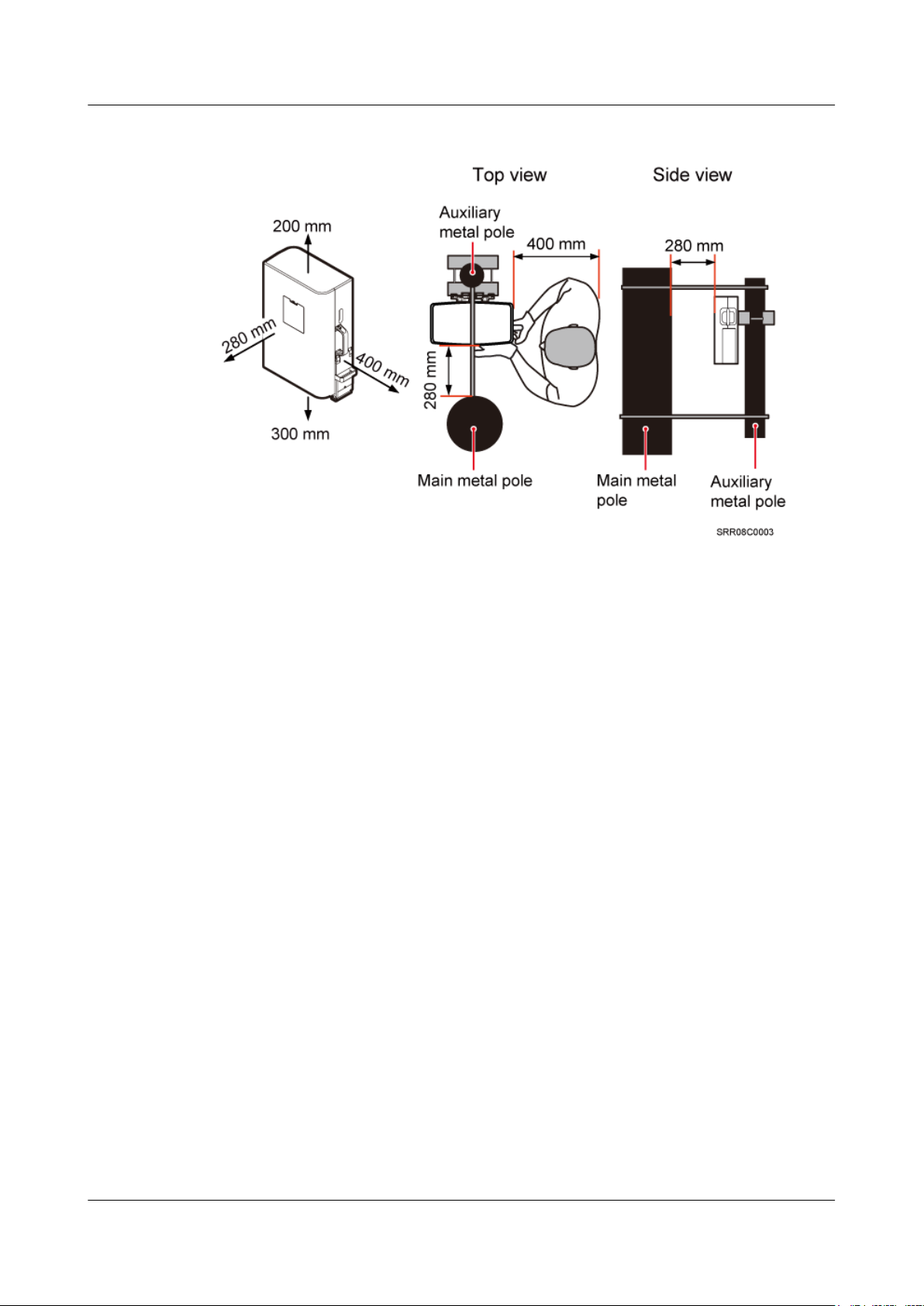
Minimum Installation Clearance for a Single RRU
Figure 3-14 shows the minimum installation clearance for a single RRU.
Figure 3-14 Minimum installation clearance for a single RRU
Minimum Installation Clearance for a Single RRU Installed on a Tower
Figure 3-15 shows the minimum installation clearance for a single RRU installed on a tower.
Issue () Huawei Proprietary and Confidential
Copyright © Huawei Technologies Co., Ltd.
16
RRU3942
Installation Guide 3 Information About the Installation
Figure 3-15 Minimum installation clearance for a single RRU installed on a tower
3.5.2 Installation Clearance for Multiple RRUs
This section describes the recommended and minimum installation clearance for multiple RRUs.
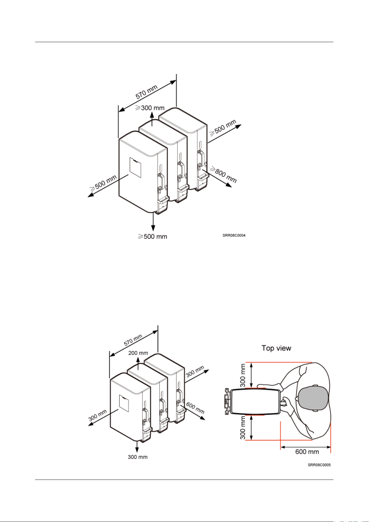
Recommended Installation Clearance for Multiple RRUs Installed in Centralized
Mode
Figure 3-16 shows the recommended installation clearance for multiple RRUs installed in
centralized mode.
Issue () Huawei Proprietary and Confidential
Copyright © Huawei Technologies Co., Ltd.
17
RRU3942
Installation Guide 3 Information About the Installation
Figure 3-16 Recommended installation clearance for multiple RRUs installed in centralized
mode
Minimum Installation Clearance for Multiple RRUs Installed in Centralized Mode
Figure 3-17 shows the minimum installation clearance for multiple RRUs installed in centralized
mode.
Figure 3-17 Minimum installation clearance for multiple RRUs installed in centralized mode
Issue () Huawei Proprietary and Confidential
Copyright © Huawei Technologies Co., Ltd.
18
RRU3942
Installation Guide 3 Information About the Installation
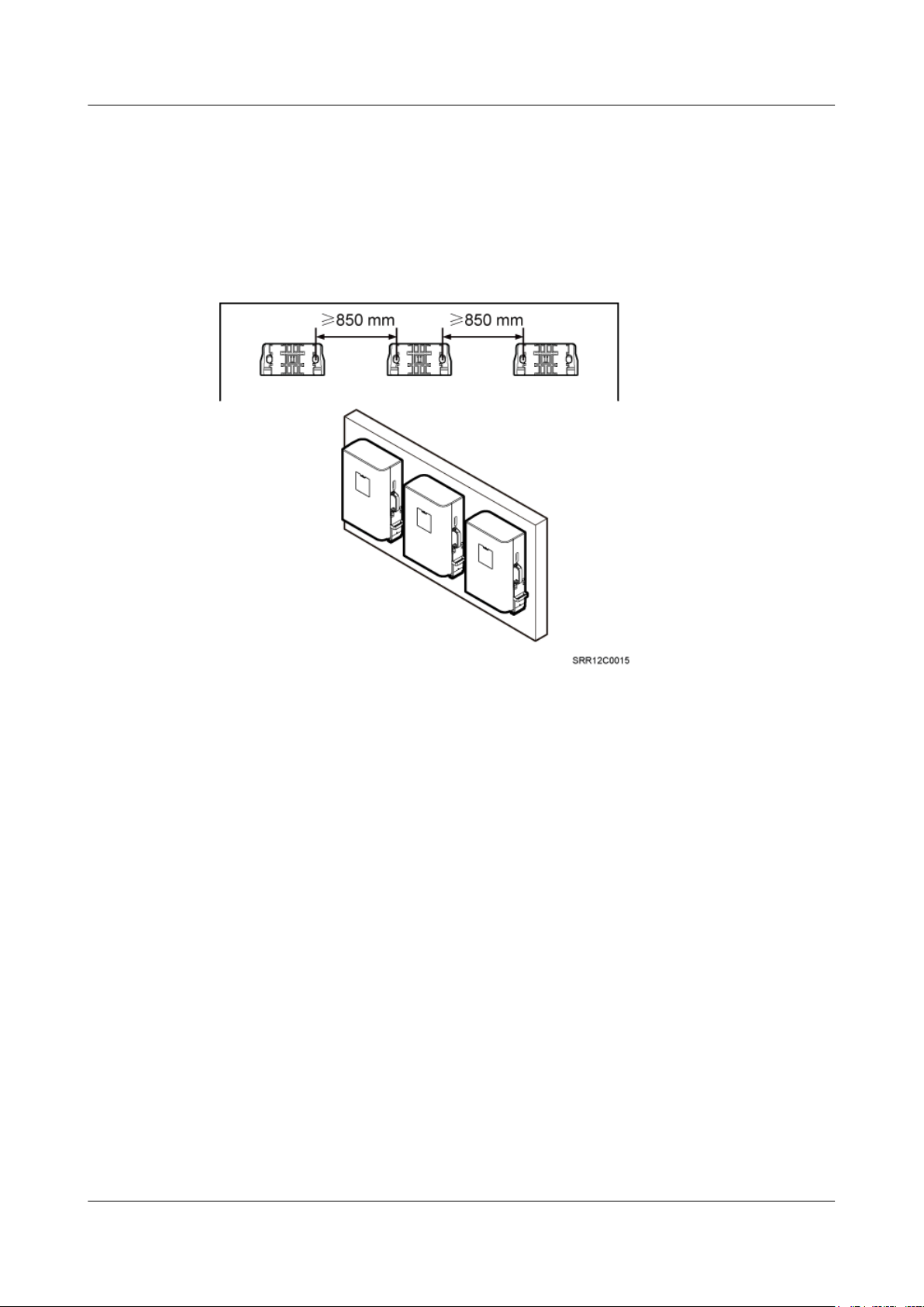
Recommended Clearance for Multiple RRUs Installed on a Wall in Standard Mode
Figure 3-18 shows the recommended clearance for multiple RRUs installed on a wall in standard
mode.
Figure 3-18 Recommended clearance for multiple RRUs installed on a wall in standard mode
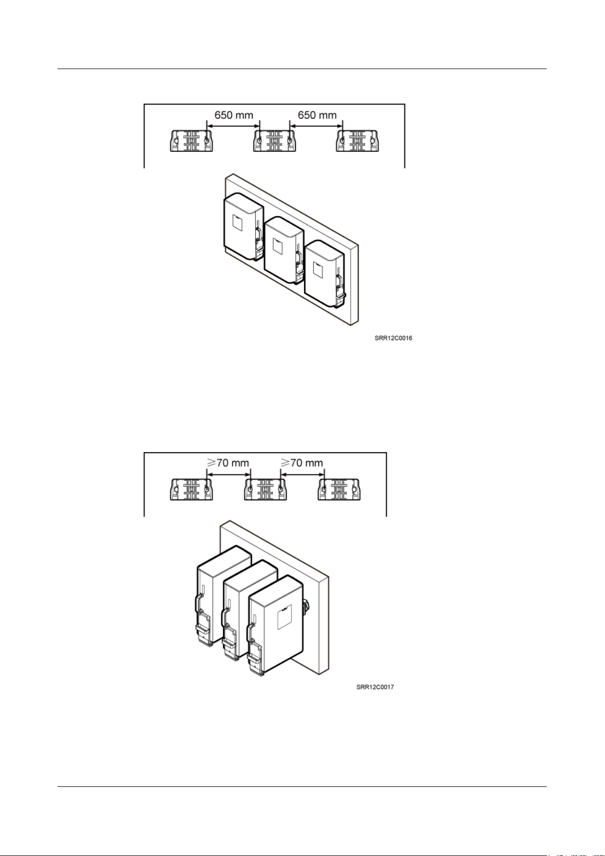
Minimum Clearance for Multiple RRUs Installed on a Wall in Standard Mode
Figure 3-19 shows the minimum clearance for multiple RRUs installed on a wall in standard
mode.
Issue () Huawei Proprietary and Confidential
Copyright © Huawei Technologies Co., Ltd.
19
RRU3942
Installation Guide 3 Information About the Installation
Figure 3-19 Minimum clearance for multiple RRUs installed on a wall in standard mode
Recommended Clearance for Multiple RRUs Side-Mounted on a Wall
Figure 3-20 shows the recommended clearance for multiple RRUs side-mounted on a wall.
Figure 3-20 Recommended clearance for multiple RRUs side-mounted on a wall
3.5.3 Installation Spacing Between RRUs
This section describes the horizontal and vertical installation spacing between RRUs.
Issue () Huawei Proprietary and Confidential
Copyright © Huawei Technologies Co., Ltd.
20
RRU3942
Installation Guide 3 Information About the Installation
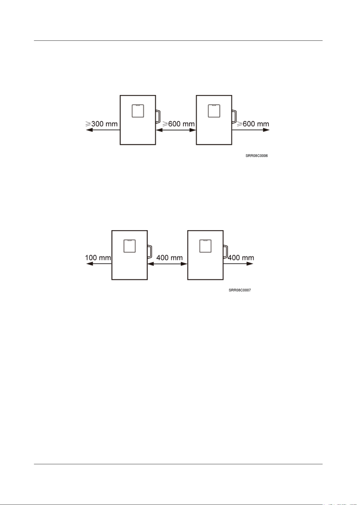
Recommended Horizontal Spacing Between RRUs
Figure 3-21 shows the recommended horizontal spacing between RRUs.
Figure 3-21 Recommended horizontal spacing between RRUs
Minimum Horizontal Spacing Between RRUs
Figure 3-22 shows the minimum horizontal spacing between RRUs.
Figure 3-22 Minimum horizontal spacing between RRUs
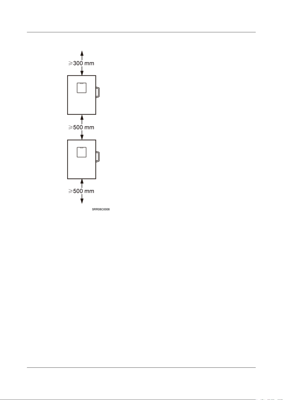
Recommended Vertical Spacing Between RRUs
Figure 3-23 shows the recommended vertical spacing between RRUs.
Issue () Huawei Proprietary and Confidential
Copyright © Huawei Technologies Co., Ltd.
21
RRU3942
Installation Guide 3 Information About the Installation
Figure 3-23 Recommended vertical spacing between RRUs
Minimum Vertical Spacing Between RRUs
Figure 3-24 shows the minimum vertical spacing between RRUs.
Issue () Huawei Proprietary and Confidential
Copyright © Huawei Technologies Co., Ltd.
22
 Loading...