

Page 1

Airbridge DBS3900 CDMA Base Station
V400R006C08
Product Description
Issue 11
Date 2010-06-18
HUAWEI TECHNOLOGIES CO., LTD.
Page 2

Copyright © Huawei Technologies Co., Lt d. 2010 . All right s reserv ed.
No part of this document may be reproduced or transmitted in any form or by any means without prior
written consent of Huawei Technologies Co., Ltd.
Trademarks and Permissions
and other Huawei trademarks are trademarks of Huawei Technologies Co., Ltd.
All other trademarks and trade names mentioned in this document are the property of their respective
holders.
Notice
The purchased products, services and features are stipulated by the contract made between Huawei and
the customer. All or part of the products, services and features described in this document may not be
within the purchase scope or the usage scope. Unless otherwise specified in the contract, all statements,
information, and recommendations in this document are provided "AS IS" without warranties, guarantees or
representations of any kind, either express or implied.
The information in this document is subject to change without notice. Every effort has been made in the
preparation of this document to ensure accuracy of the contents, but all statements, information, and
recommendations in this document do not constitute the warranty of any kind, express or implied.
Huawei Technologies Co., Ltd.
Address: Huawei Industrial Base
Bantian, Longgang
Shenzhen 518129
People's Republic of China
Website: http://www.huawei.com
Email: support@huawei.com
Issue 11 (2010-06-18)
Huawei Proprietary and Confidential
Copyright © Huawei Technologies Co., Ltd.
i
Page 3

Airbridge DBS3900 CDMA Base Station
Product Description About This Document
About This Document
Purpose
This document describes the overall structure, logical structure, auxiliary devices,
configuration principles, and networking modes of the DBS3900. In addition, this document
describes the transmit and receive performance, physical and electrical specifications,
lightning protection performance, and environmental requirements of the DBS3900. You can
obtain a comprehensive understanding of the DBS3900 by reading this document.
Product Version
The following table lists the product version related to this document.
Product Name Product Version
DBS3900 CDMA V400R006C08
Intended Audience
This document is intended for:
z
Field engineers
z
System engineers
Change History
Version Change History
11 (2010-06-18) The modifications in this version are as
follows:
z
Product version update.
10 (2010-03-18) The modifications in this version are as
follows:
z
Product version update.
Issue 11 (2010-06-18) Huawei Proprietary and Confidential
Copyright © Huawei Technologies Co., Ltd.
iii
Page 4

About This Document
Airbridge DBS3900 CDMA Base Station
Product Description
Version Change History
09 (2009-12-25) Ninth release of the DBS3900 V400R006.
08 (2009-09-15) The modifications in this version are as
follows:
z
The contents related to the AWS band
classes supported by the AC RRU3606
are added.
07 (2009-08-30) Seventh release of the DBS3900 V400R006.
06 (2009-08-15) Sixth release of the DBS3900 V400R006.
05 (2009-07-07) Fifty release of the DBS3900 V400R006.
04 (2009-05-30) The modifications in this version are as
follows:
z
The descriptions of the UBRI and UEIU
are added.
03 (2009-04-01) The modifications in this version are as
follows:
z
The contents related to the AC RRU3606
are added.
z
The contents related to the CMPT (8 E1)
are added.
z
The contents related to the 450 MHz band
classes supported by the DC RRU3606
are added.
02 (2008-08-10) The modifications in this version are as
01(2008-06-25) Initial release of the DBS3900 V400R006.
Organization
1 Overall Structure of the DBS3900
This describes the overall structure of the DBS3900, which consists of the BBU3900,
RRU3606, cables, antenna system, and auxiliary equipment.
2 Solutions for the Auxiliary Devices of the DBS3900
follows:
z
The networking of the DBS3900 is
deleted, and the transmission and
networking of the BTS are added.
z
The contents related to the operation and
maintenance of the BTS are modified.
z
The performance measurement items of
the DBS3900 are modified.
iv Huawei Proprietary and Confidential
Copyright © Huawei Technologies Co., Ltd.
Issue 11 (2010-06-18)
Page 5
Airbridge DBS3900 CDMA Base Station
Product Description About This Document
This describes the solutions for the auxiliary devices of the DBS3900. The DBS3900 uses a
modular structure. The basic modules of the DBS3900 are the BBU3900 and RRU3606. The
auxiliary devices of the DBS3900 include the indoor centralized installation rack, L-shaped
support, APM, storage battery cabinet, DCDU, EMUA, SLPU, ODF, DDF, DC power system,
and AC power system. The basic modules and auxiliary devices can be flexibly configured to
form integrated site solutions.
3 Configuration Principles of the DBS3900
This describes the configuration principles of the DBS3900, covering the configurations of
the BBU3900, RRU3606, power supply, and satellite synchronization antenna.
4 Transmission and Networking of the BTS
This describes the transmission and networking of the BTS. The networking modes supported
by the BTS are the star networking mode, chain networking mode, and tree networking mode.
5 Operation and Maintenance of the BTS
This section describes the operation and maintenance of the BTS. The operation and
maintenance of the BTS refers to the management, monitoring, and maintenance of the BTS.
The BTS provides various methods and platforms for operation and maintenance to cater to
different scenarios.
6 Technical Specifications of the DBS3900
This describes the technical specifications of the DBS3900.
Conventions
Symbol Conventions
The symbols that may be found in this document are defined as follows.
Symbol Description
Indicates a hazard with a high level of risk that, if not avoided,
will result in death or serious injury.
Indicates a hazard with a medium or low level of risk which, if
not avoided, could result in minor or moderate injury.
Indicates a potentially hazardous situation that, if not avoided,
could cause equipment damage, data loss, and performance
degradation, or unexpected results.
Issue 11 (2010-06-18) Huawei Proprietary and Confidential
Copyright © Huawei Technologies Co., Ltd.
Indicates a tip that may help you solve a problem or save time.
Provides additional information to emphasize or supplement
important points of the main text.
v
Page 6

About This Document
General Conventions
Convention Description
Times New Roman Normal paragraphs are in Times New Roman.
Airbridge DBS3900 CDMA Base Station
Product Description
Boldface
Italic Book titles are in italics.
Courier New
Command Conventions
Convention Description
Boldface
Italic Command arguments are in italics.
[ ] Items (keywords or arguments) in square brackets [ ] are
{ x | y | ... } Alternative items are grouped in braces and separated by
[ x | y | ... ] Optional alternative items are grouped in square brackets
Names of files, directories, folders, and users are in
boldface. For example, log in as user root.
Terminal display is in Courier New.
The keywords of a command line are in boldface.
optional.
vertical bars. One is selected.
and separated by vertical bars. One or none is selected.
{ x | y | ... } * Alternative items are grouped in braces and separated by
GUI Conventions
Convention Description
Boldface
> Multi-level menus are in boldface and separated by the ">"
Keyboard Operation
Format Description
Key
vertical bars. A minimum of one or a maximum of all can
be selected.
Buttons, menus, parameters, tabs, windows, and dialog titles
are in boldface. For example, click OK.
signs. For example, choose File > Create > Folder.
Press the key. For example, press Enter and press Tab.
vi Huawei Proprietary and Confidential
Copyright © Huawei Technologies Co., Ltd.
Issue 11 (2010-06-18)
Page 7

Airbridge DBS3900 CDMA Base Station
Product Description About This Document
Format Description
Key 1+Key 2
Key 1, Key 2 Press the keys in turn. For example, pressing Alt, A means
Mouse Operation
Action Description
Click Select and release the primary mouse button without
Double-click Press the primary mouse button twice continuously and
Drag Press and hold the primary mouse button and move the
Press the keys concurrently. For example, pressing
Ctrl+Alt+A means the three keys should be pressed
concurrently.
the two keys should be pressed in turn.
moving the pointer.
quickly without moving the pointer.
pointer to a certain position.
Issue 11 (2010-06-18) Huawei Proprietary and Confidential
Copyright © Huawei Technologies Co., Ltd.
vii
Page 8

Airbridge DBS3900 CDMA Base Station
Product Description Contents
Contents
About This Document...................................................................................................................iii
1 Overall Structure of the DBS3900...........................................................................................1-1
1.1 Physical Structure of the DBS3900...............................................................................................................1-3
1.2 Physical Ports of the DBS3900 .....................................................................................................................1-6
1.2.1 Ports on the BBU3900 .........................................................................................................................1-6
1.2.2 Physical Ports of the RRU3606..........................................................................................................1-10
1.3 Logical Structure of the DBS3900 .............................................................................................................. 1-12
1.3.1 Functional Structure of the BBU3900................................................................................................1-12
1.3.2 Logical Structure of the RRU3606.....................................................................................................1-13
1.4 Software Structure of the BTS ....................................................................................................................1-13
2 Solutions for the Auxiliary Devices of the DBS3900..........................................................2-1
2.1 Indoor Centralized Installation of the DBS3900...........................................................................................2-2
2.2 Indoor Distributed Installation of the DBS3900............................................................................................2-3
2.3 Outdoor Centralized Installation of the DBS3900 ........................................................................................2-4
2.4 Outdoor Distributed Installation of the DBS3900.........................................................................................2-6
3 Configuration Principles of the DBS3900.............................................................................3-1
3.1 Configuration Principles of the BBU3900 ....................................................................................................3-1
3.2 Configuration Principles of the RRU3606 ....................................................................................................3-3
3.3 Configuration Principles of the Power Supply..............................................................................................3-3
3.4 Configuration Requirements of the RF Antennas..........................................................................................3-4
3.5 Configuration Principles of the Satellite Synchronization Antenna ..............................................................3-4
3.6 Typical Configurations of the DBS3900 .......................................................................................................3-5
4 Transmission and Networking of the BTS ...........................................................................4-1
4.1 Star Networking Mode..................................................................................................................................4-1
4.2 Chain Networking Mode...............................................................................................................................4-2
4.3 Tree Networking Mode .................................................................................................................................4-3
5 Operation and Maintenance of the BTS................................................................................5-1
5.1 Operation and Maintenance Modes of the BTS ............................................................................................5-1
5.2 Operation and Maintenance Functions of the BTS .......................................................................................5-2
6 Technical Specifications of the DBS3900..............................................................................6-1
Issue 11 (2010-06-18) Huawei Proprietary and Confidential
Copyright © Huawei Technologies Co., Ltd.
ix
Page 9

Contents
Airbridge DBS3900 CDMA Base Station
Product Description
6.1 Performance Specifications of the DBS3900................................................................................................6-1
6.2 Physical and Electrical Specifications of the DBS3900................................................................................ 6-6
6.2.1 Technical Specifications of the BBU3900 ...........................................................................................6-6
6.2.2 Technical Specifications of the RRU3606 ...........................................................................................6-7
6.3 Reliability Specifications of the DBS3900....................................................................................................6-9
6.4 Lightning Protection Specifications of the DBS3900 ...................................................................................6-9
6.5 Safety Specifications of the DBS3900 ........................................................................................................6-10
6.6 EMC Specifications of the DBS3900..........................................................................................................6-11
6.7 Environmental Specifications of the DBS3900........................................................................................... 6-12
6.7.1 Storage Environment..........................................................................................................................6-12
6.7.2 Transportation Environment ..............................................................................................................6-15
6.7.3 Requirements for the Running Environment of the DBS3900...........................................................6-19
x Huawei Proprietary and Confidential
Copyright © Huawei Technologies Co., Ltd.
Issue 11 (2010-06-18)
Page 10

Airbridge DBS3900 CDMA Base Station
Product Description Figures
Figures
Figure 1-1 Hardware structure of the DBS3900.................................................................................................1-1
Figure 1-2 Major functional modules of the DBS3900......................................................................................1-3
Figure 1-3 BBU3900..........................................................................................................................................1-3
Figure 1-4 Configuration of the BBU3900.........................................................................................................1-3
Figure 1-5 DC RRU3606 ...................................................................................................................................1-5
Figure 1-6 AC RRU3606....................................................................................................................................1-6
Figure 1-7 Logical structure of the RRU3606.................................................................................................. 1-13
Figure 1-8 Software structure of the BTS ........................................................................................................1-14
Figure 2-1 Indoor Centralized Installation of the DBS3900...............................................................................2-2
Figure 2-2 Indoor distributed installation...........................................................................................................2-4
Figure 2-3 Outdoor centralized installation of the DBS3900.............................................................................2-5
Figure 2-4 Outdoor distributed installation of the DBS3900 .............................................................................2-7
Figure 4-1 Star networking mode.......................................................................................................................4-2
Figure 4-2 Chain networking mode....................................................................................................................4-3
Figure 4-3 Tree networking mode ......................................................................................................................4-4
Figure 5-1 Networking of the operation and maintenance system .....................................................................5-2
Figure 6-1 Dimensions of the BBU3900............................................................................................................6-7
Issue 11 (2010-06-18) Huawei Proprietary and Confidential
Copyright © Huawei Technologies Co., Ltd.
xi
Page 11

Airbridge DBS3900 CDMA Base Station
Product Description Tables
Tables
Table 1-1 Boards in the BBU3900......................................................................................................................1-4
Table 1-2 Ports on the RRU3606 (DC type) ..................................................................................................... 1-10
Table 1-3 Ports on the RRU3606 (AC type) ..................................................................................................... 1-11
Table 2-1 Auxiliary devices used in the door distributed installation of the DBS3900 ......................................2-3
Table 2-2 Auxiliary devices used in the door distributed installation of the DBS3900 ......................................2-4
Table 2-3 Auxiliary devices used in the outdoor distributed installation of the DBS3900.................................2-6
Table 2-4 Auxiliary devices used in the door distributed installation of the DBS3900 ......................................2-7
Table 3-1 Power supply configuration in indoor installation..............................................................................3-3
Table 3-2 Power supply configuration in outdoor installation............................................................................3-4
Table 6-1 Transmit specifications in band class 0 (800 MHz)............................................................................6-2
Table 6-2 Receive specifications in band class 0 (800 MHz) .............................................................................6-2
Table 6-3 Transmit specifications in band class 1 (1900 MHz)..........................................................................6-2
Table 6-4 Receive specifications in band class 1 (1900 MHz) ...........................................................................6-3
Table 6-5 Transmit specifications in band class 5 (450 MHz)............................................................................6-3
Table 6-6 Receive specifications in band class 5 (450 MHz) .............................................................................6-3
Table 6-7 Transmit specifications in band class 14 (1900 MHz)........................................................................6-4
Table 6-8 Receive specifications in band class 14 (1900 MHz) .........................................................................6-4
Table 6-9 Transmit specifications in band class 15 (AWS) ................................................................................6-4
Table 6-10 Receive specifications in band class 15 (AWS)................................................................................ 6-5
Table 6-11 RRU3606 cascading specifications of the DBS3900........................................................................6-5
Table 6-12 BER threshold specifications of BTS transmission links .................................................................6-6
Table 6-13 Technical specifications of the BBU3900.........................................................................................6-7
Table 6-14 Technical specifications of the RRU3606 (DC type)........................................................................6-7
Table 6-15 Technical specifications of the RRU3606 (AC type)........................................................................6-8
Table 6-16 Reliability specifications of the DBS3900........................................................................................6-9
Table 6-17 Lightning protection specifications of the DBS3900........................................................................6-9
Issue 11 (2010-06-18) Huawei Proprietary and Confidential
Copyright © Huawei Technologies Co., Ltd.
xiii
Page 12

Airbridge DBS3900 CDMA Base Station
Tables
Table 6-18 Climatic requirements for the storage environment of the equipment............................................6-13
Table 6-19 Requirements for the concentration of mechanically active substances in the storage environment of
the equipment....................................................................................................................................................6-14
Table 6-20 Requirements for the concentration of chemically active substances in the storage environment of
the equipment....................................................................................................................................................6-14
Table 6-21 Requirements for the mechanical stress in the storage environment of the BBU........................... 6-15
Table 6-22 Requirements for the mechanical stress in the storage environment of the RRU........................... 6-15
Table 6-23 Climatic requirements for the transportation environment of the equipment .................................6-16
Table 6-24 Requirements for the concentration of mechanically active substances in the transportation
environment of the equipment...........................................................................................................................6-17
Table 6-25 Requirements for the concentration of chemically active substances in the transportation
environment of the equipment...........................................................................................................................6-17
Table 6-26 Requirements for the mechanical stress in the transportation environment of the BBU ................6-18
Table 6-27 Requirements for the mechanical stress in the transportation environment of the RRU ................6-18
Table 6-28 Climatic requirements for the running environment of the equipment...........................................6-19
Product Description
Table 6-29 Requirements for the concentration of mechanically active substances in the running environment of
the equipment....................................................................................................................................................6-20
Table 6-30 Requirements for the concentration of chemically active substances in the running environment of
the BBU.............................................................................................................................................................6-20
Table 6-31 Requirements for the concentration of chemically active substances in the running environment of
the RRU.............................................................................................................................................................6-20
Table 6-32 Requirements for the mechanical stress in the running environment of the BBU..........................6-21
Table 6-33 Requirements for the mechanical stress in the running environment of the RRU..........................6-21
xiv Huawei Proprietary and Confidential
Copyright © Huawei Technologies Co., Ltd.
Issue 11 (2010-06-18)
Page 13
Airbridge DBS3900 CDMA Base Station
Product Description 1 Overall Structure of the DBS3900
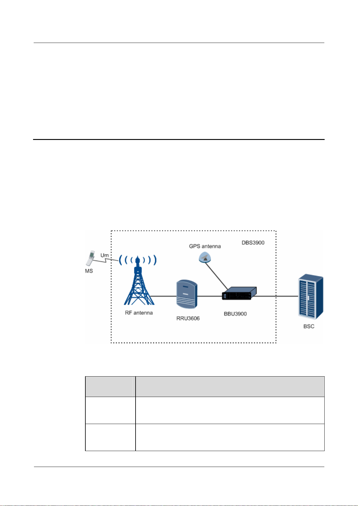
1 Overall Structure of the DBS3900
About This Chapter
This describes the overall structure of the DBS3900, which consists of the BBU3900,
RRU3606, cables, antenna system, and auxiliary equipment.
Figure 1-1 shows the hardware structure of the DBS3900.
Figure 1-1 Hardware structure of the DBS3900
Functional Modules of the DBS3900
Functional
Module
Description
BBU3900 Being the baseband unit of the DBS3900, this component is responsible
for resource management, operation and maintenance, and environment
monitoring of the system.
RRU3606 Being the remote RF module unit of the DBS3900, this component is
responsible for transmitting and receiving radio signals to achieve
communications between the wireless network system and the MSs.
Issue 11 (2010-06-18) Huawei Proprietary and Confidential
Copyright © Huawei Technologies Co., Ltd.
1-1
Page 14

1 Overall Structure of the DBS3900
There are two types of RRU3606s. One type uses DC power supply whereas the other type uses AC
power supply.
The band classes that the DC RRU3606 and AC RRU3606 support are as follows:
z
The DC RRU3606 supports the 450 MHz, 800 MHz, 1900 MHz, and AWS band classes.
z
The AC RRU3606 supports the 800 MHz A and AWS band classes.
Composition of the DBS3900
Device Description
APM30 The APM30 is an integrated power system for outdoor use and
Airbridge DBS3900 CDMA Base Station
Product Description
has the following features:
z
Supporting -48 V DC and 110/220 V AC power supply
z
Providing at most 12 U space for user equipment when not
configured with additional devices
z
Supporting internal storage batteries in the case of AC input
z
Supporting piled installation with the storage battery cabinet
(under the APM30 cabinet), which is optional
DCDU The DCDU is a power distribution box and supports one DC
input and nine DC outputs.
EMUA The EMUA is an environment monitoring unit and implements
monitoring for the site environment and user equipment.
For details on the functions of the EMUA, see the EMUA User
Guide.
SLPU The SLPU is a lightning protection unit, which is used to
configure the UELP and UFLP. It implements lightning
protection for E1/T1 and FE/GE signals.
DDF DDFs are classified into two types, which are used for coaxial
cables and twisted-pair cables respectively. A DDF is required
when the transmission equipment and BBU3900 are configured
in the same cabinet.
DC power system Made up of PSU
modules, the DC power system converts
DC/DC
+24 V DC input to -48 V DC output.
AC power system Made up of PSU
modules and PMU modules, the AC
AC/DC
power system converts 220/110 V AC input to -48 V DC
output.
1.1 Physical Structure of the DBS3900
This describes the physical structure of the DBS3900, which consists of the BBU3900,
RRU3606, and auxiliary equipment.
1.2 Physical Ports of the DBS3900
This describes the physical ports of the DBS3900.
1-2 Huawei Proprietary and Confidential
Copyright © Huawei Technologies Co., Ltd.
Issue 11 (2010-06-18)
Page 15
Airbridge DBS3900 CDMA Base Station
Product Description 1 Overall Structure of the DBS3900
1.3 Logical Structure of the DBS3900
This describes the logical structure of the DBS3900.
1.4 Software Structure of the BTS
This section describes the software structure of the BTS. The BTS software consists of the
platform software, signaling protocol software, operation and maintenance software, and data
center.
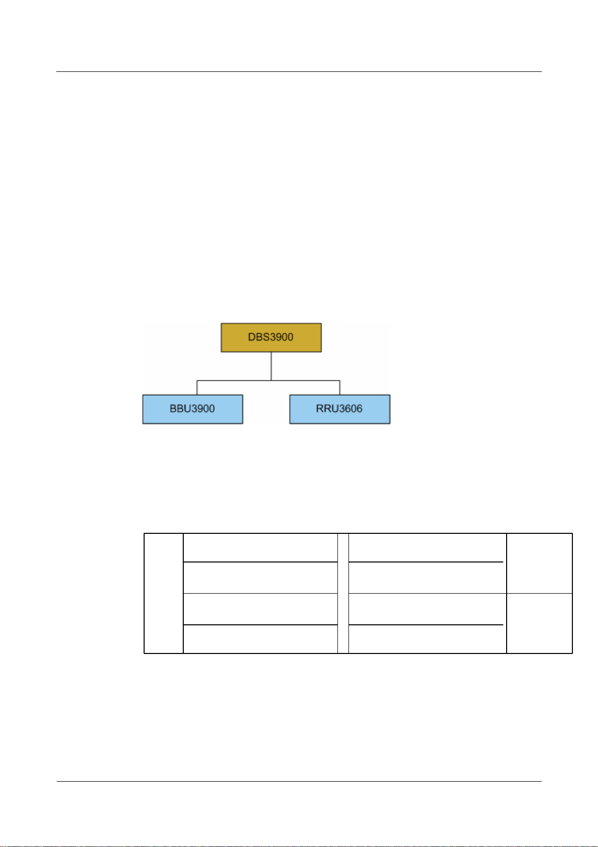
1.1 Physical Structure of the DBS3900
This describes the physical structure of the DBS3900, which consists of the BBU3900,
RRU3606, and auxiliary equipment.
Figure 1-2 shows the major functional modules of the DBS3900.
Figure 1-2 Major functional modules of the DBS3900
Physical Structure of the BBU3900
Figure 1-4 shows the configuration of the BBU3900.
Figure 1-3 Configuration of the BBU3900
HCPM/HECM
0
HCPM/HECM/USCU
1
FAN
HCPM/HECM/USCU/LBBP
2
HCPM/HECM/UBRI
3
HCPM/HECM/UTRP/UELP/UFLP
4
HCPM/HECM/UTRP/UELP/UFLP/USCU
5
CMPT/USCU/LMPT
6
CMPT
7
UPEU/UEIU
0
UPEU
1
Issue 11 (2010-06-18) Huawei Proprietary and Confidential
Copyright © Huawei Technologies Co., Ltd.
1-3
Page 16

1 Overall Structure of the DBS3900
Table 1-1 Boards in the BBU3900
Module Expansion Description Function
Airbridge DBS3900 CDMA Base Station
Product Description
CMPT CDMA Main
Processing&Tra
nsmission Unit
It is the main
processing and
transmission
module.
HCPM HERT Channel
Processing
Module
It is the 1X
channel
processing
module.
HECM HERT Enhance
Channel
Processing
Module
LMPT LTE Main
Processing &
Transmission
It is the EV-DO
channel
processing
module.
It is LTE main
control and
transmission unit.
Unit
LBBP LTE BaseBand
Processing unit
It is LTE
BaseBand
Processing unit.
UTRP Universal
Extension
Transmission
Processing Unit
It is the universal
extension
transmission
processing unit.
It processes and transmits data
between the BTS and the BSC,
controls and manages the entire
BTS, and provides clock signals
for the BTS system.
It processes the 1X service data
on forward and reverse channels.
It processes the EV-DO service
data on forward and reverse
channels.
It manages the entire eNodeB in
terms of OM and signaling
processing and provides clock
signals for the BBU3900.
It processes the baseband signals
and Common Public Radio
Interface (CPRI) signals.
It provides connection between
the BBU3900 and the BSC, and
supports IP transmission over
E1/T1 links.
UBRI Universal
Baseband Radio
Interface Unit
UEIU Universal
Environment
Interface Unit
UELP Universal E1/T1
Lightning
Protection Unit
UFLP Universal
FE/GE
Lightning
It is the universal
extension radio
interface unit.
It is the universal
environment
interface unit.
It is the universal
E1/T1 surge
protection unit.
It is the FE/GE
surge protection
unit.
Protection Unit
FAN FAN Unit It is the FAN unit
of the BBU3900.
It implements the functions of PN
sharing, 1X resource pool, and
convergence and distribution of
baseband data.
It provides the environment
monitoring signal port for the
BBU3900.
It provides surge protection for
E1/T1 signals.
It provides surge protection for
FE signals.
It implements heat dissipation for
the BBU3900.
1-4 Huawei Proprietary and Confidential
Copyright © Huawei Technologies Co., Ltd.
Issue 11 (2010-06-18)
Page 17
Airbridge DBS3900 CDMA Base Station
Product Description 1 Overall Structure of the DBS3900
Module Expansion Description Function
UPEU Universal Power
and
Environment
Interface Unit
USCU Universal
Satellite Card
and Clock Unit
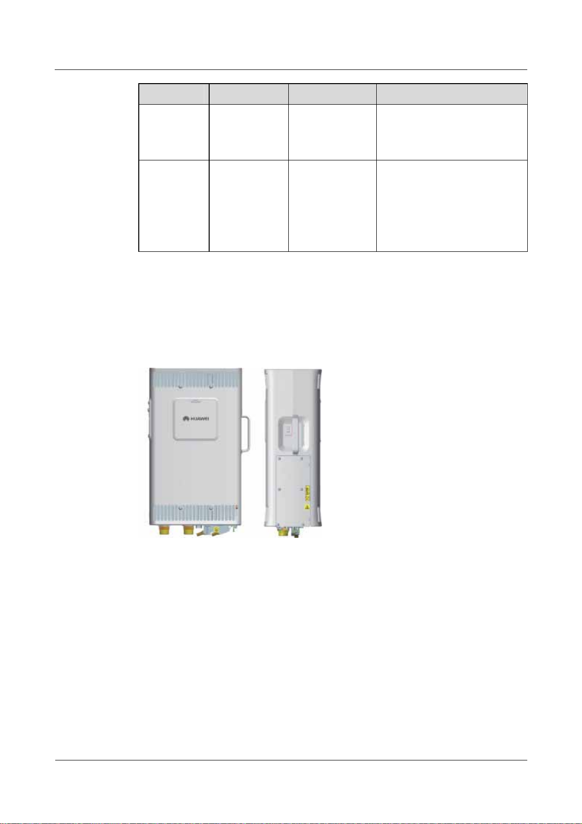
Physical Structure of the RRU3606
The RRU3606 is of two types, that is, the DC RRU3606 and the AC RRU3606, as shown in
Figure 1-5 and Figure 1-6.
Figure 1-4 DC RRU3606
It is the universal
power and
environment
interface unit.
It is the universal
satellite card and
clock unit.
It converts -48 V DC or +24 V
DC to +12 V DC and provides
environment monitoring signal
ports for the BBU3900.
It provides the input port for
external signals (including
satellite clock signals), and
provides synchronization clock
signals for the BBU3900 and for
the RF modules connected to the
BBU3900.
Issue 11 (2010-06-18) Huawei Proprietary and Confidential
Copyright © Huawei Technologies Co., Ltd.
1-5
Page 18
1 Overall Structure of the DBS3900
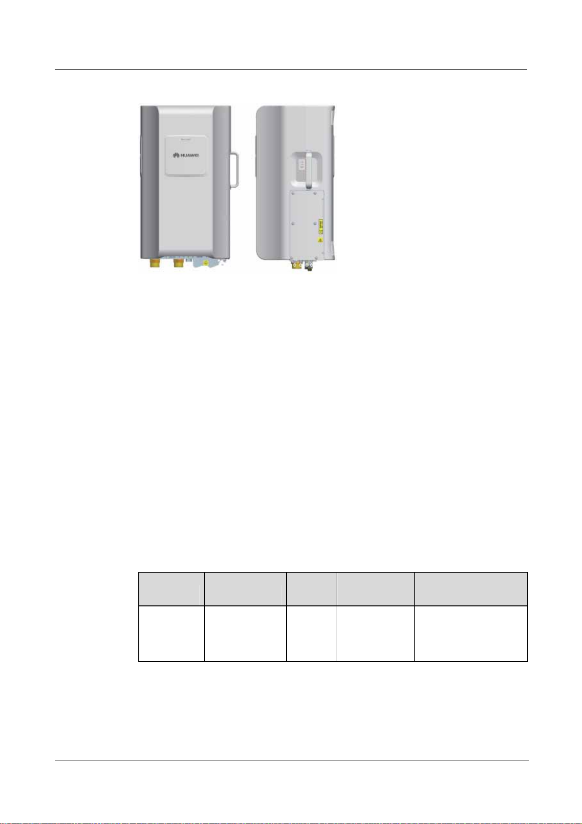
Figure 1-5 AC RRU3606
Airbridge DBS3900 CDMA Base Station
Product Description
1.2 Physical Ports of the DBS3900
This describes the physical ports of the DBS3900.
1.2.1 Ports on the BBU3900
The ports of the BBU3900 consist of the power ports, transmission ports, alarm ports,
reserved ports, and ports connected to other equipment.
1.2.2 Physical Ports of the RRU3606
The physical ports of the RRU3606 include power ports, transmission ports, alarm ports,
grounding ports, and RF ports. The physical ports of the DC RRU3606 slightly different from
those of the AC RRU3606.
1.2.1 Ports on the BBU3900
The ports of the BBU3900 consist of the power ports, transmission ports, alarm ports,
reserved ports, and ports connected to other equipment.
Ports on Mandatory Boards
Quantity Connector
Board Port
CMPT (4
E1)
E1/T1 1 DB26 It is a transmission port,
Type
Function
which is connected to
the BSC and provides
four E1/T1 links.
1-6 Huawei Proprietary and Confidential
Copyright © Huawei Technologies Co., Ltd.
Issue 11 (2010-06-18)
Page 19

Airbridge DBS3900 CDMA Base Station
Product Description 1 Overall Structure of the DBS3900
Quantity Connector
Board Port
Type
Function
FE0 1 RJ45 It is the transmission
port, which is connected
to the BSC and provides
one FE link.
FE electrical port,
supporting cable
connection
FE1 1 SFP It is the transmission
port, which is connected
to the BSC and provides
one FE link.
FE optical port,
supporting optical
cables (a removable
optical module is
required)
CMPT (8
E1)
USB 1 USB It is reserved.
TST 1 USB It is a clock test port.
ETH 1 RJ45 It is a commissioning
port for local
maintenance.
GPS 1 SMA It is used for GPS signal
input.
E1/T1 1 DB44 It is a transmission port,
which is connected to
the BSC and provides
eight E1/T1 links.
FE0 1 RJ45 It is a transmission port,
which is connected to
the BSC and provides
one FE link.
It is an FE electrical port
supporting cable
connection.
USB 1 USB It is reserved.
TST 1 USB It is a clock test port.
ETH 1 RJ45 It is a commissioning
GPS 1 SMA It is used for GPS signal
Issue 11 (2010-06-18) Huawei Proprietary and Confidential
Copyright © Huawei Technologies Co., Ltd.
port for local
maintenance.
input.
1-7
Page 20

1 Overall Structure of the DBS3900
Board Port
HCPM/HECM SFP 3 SFP They are connected to
LMPT
Airbridge DBS3900 CDMA Base Station
Product Description
Quantity Connector
Type
Function
the RF module.
SFP 0 and SFP 1 2
LC
Indicate Ethernet optical
ports, which are used to
connect to the
transmission device or
gateway
USB 1 USB Loads software to the
board
LBBP
UPEU
TST
1
USB Test
ETH 1 RJ-45 Debug
FE/GE0 and
FE/GE
2 RJ-45 Indicate Ethernet
electrical ports, which
are used for connection
to the transmission
device or gateway
GPS
RST
CPRI0 to CPRI5
1 SMA Receives GPS signals
1 -
6
SFP connector Connecting to the
Resets the BBU3900
LRRU, LRFU,
RRU3606 or CRFU for
transmitting service
data, clock signals, and
synchronization
information
Power port 1 3V3 It is used for DC input.
MON0 1 RJ45
Each port provides
monitoring function for
MON1 1 RJ45
one RS485 link. There
are totally two RS485
links.
EXT-ALM0 1 RJ45
EXT-ALM1 1 RJ45
1-8 Huawei Proprietary and Confidential
Copyright © Huawei Technologies Co., Ltd.
Each port provides four
links for dry contact
alarm signal input.
There are totally eight
links of dry contact
alarm signals.
Issue 11 (2010-06-18)
Page 21

Airbridge DBS3900 CDMA Base Station
Product Description 1 Overall Structure of the DBS3900
Ports on Optional Boards
Quantity Connector
Board Port
Type
Function
UELP
UFLP
USCU0
INSIDE 1 DB25 It provides four links for
E1/T1 signal input and
is connected to the
BBU.
OUTSIDE 1 DB26 It provides four links for
E1/T1 signal output, and
connects the
transmission equipment
and the BSC.
FE0 and FE1
(INSIDE)
2 RJ45 Each port provides one
link for FE signal input
and is connected to the
BBU.
FE0 and FE1
(OUTSIDE)
2 RJ45 Each port provides four
links for E1/T1 signal
output and connects the
transmission equipment
and the BSC.
GPS port 1 SMA It is used for receiving
GPS signals.
RGPS port 3 8-pin terminal
block
They are used for
receiving RGPS signals.
USCUb0
BITS port 1 SMA It is connected to the
BITS clock.
TEST port 1 SMA It is used as the output
end for the clock test.
GPS port 1 SMA It is used for receiving
GPS signals.
RGPS port 2 8-pin terminal
block
They are used for
receiving RGPS signals.
TOD port 2 RJ45 They are used for
receiving or transmitting
1PPS and TOD signals.
BITS port 1 SMA It is connected to the
BITS clock and supports
the adaptive input of
2.048 MHz clock
signals and 10 MHz
clock signals.
M-1PPS port 1 SMA It is used for receiving
M1000 1PPS signals.
Issue 11 (2010-06-18) Huawei Proprietary and Confidential
Copyright © Huawei Technologies Co., Ltd.
1-9
Page 22

1 Overall Structure of the DBS3900
Board Port
UTRP E1/T1 port 2 DB26 Each port provides four
UBRI CPRI 6 SFP They are connected to
Airbridge DBS3900 CDMA Base Station
Quantity Connector
Type
Product Description
Function
E1/T1 links. There are
totally eight E1/T1 links
provided.
the RF module.
UEIU
MON0 1 RJ45
MON1 1 RJ45
EXT-ALM0 1 RJ45
EXT-ALM1 1 RJ45
1.2.2 Physical Ports of the RRU3606
The physical ports of the RRU3606 include power ports, transmission ports, alarm ports,
grounding ports, and RF ports. The physical ports of the DC RRU3606 slightly different from
those of the AC RRU3606.
Table 1-2 lists the physical ports of the DC RRU3606.
Table 1-2 Ports on the RRU3606 (DC type)
Each port provides
monitoring function for
one RS485 link. There
are totally two RS485
links.
Each port provides four
links for dry contact
alarm signal input.
There are totally eight
links of dry contact
alarm signals.
Port Type Port Description Quantity Connector
Power port
Transmissio
n port
1-10 Huawei Proprietary and Confidential
RTN (+) or
RTN (+) 0
NEG (-) or
NEG (-) 0
CPRI_E Connecting the
CPRI_W Connecting the
Copyright © Huawei Technologies Co., Ltd.
Port for -48 V DC
power supply
lower-level CPRI
port
BBU or the
upper-level CPRI
port
1 Screw
1 SFP port
1 SFP port
Issue 11 (2010-06-18)
Page 23

Airbridge DBS3900 CDMA Base Station
Product Description 1 Overall Structure of the DBS3900
Port Type Port Description Quantity Connector
Alarm port RS485/EXT
_ALM
Port for receiving
one link of RS485
1 DB15 connector
signals
Ground port - Ground screw 4 Screw
RF port
ANT_TX/R
XA
Port for TX/main
RX signals
1 Cylindrical
waterproof DIN
connector
ANT_RXB Port for diversity
RX signals
1 Cylindrical
waterproof DIN
connector
RX_IN/OUT Sharing main RX
1 2W2 connector
signals with other
RRU3606s
Communicat
ion port for
the RET
RET/PWR_
SRXU
Communication
port for the RET
antenna
1 DB9 connector
antenna
The short-circuit impedance of the alarm port is less than 0.2 kilohm, and the open-circuit impedance of
the alarm port is more than 51 kilohms.
Table 1-3 lists the physical ports of the AC RRU3606.
Table 1-3 Ports on the RRU3606 (AC type)
Type Name Description Quantity Connector Type
Power port
AC-in Port for 220 V
AC/110 V AC
power input
DC-out Port for DC power
1 3-pin round
waterproof
connector
1 output
CPRI_E CPRI port 1 SFP socket Transmissio
n port
CPRI_W CPRI port 1 SFP socket
Alarm port RS485/EXT
_ALM
Port for reporting
AC power failure
1 DB15 connector
alarms
Ground port - - 4 -
RF port ANT_TX/R
XA
Port for TX/main
RX signals
1 DIN round
waterproof
connector
Issue 11 (2010-06-18) Huawei Proprietary and Confidential
Copyright © Huawei Technologies Co., Ltd.
1-11
Page 24

1 Overall Structure of the DBS3900
Type Name Description Quantity Connector Type
Airbridge DBS3900 CDMA Base Station
Product Description
ANT_RXB Port for diversity
RX signals
RX_IN/OUT Sharing main RX
signals with other
RRU3606s
Communicat
ion port for
the RET
RET/PWR_
SRXU
Communication
port for the RET
antenna
antenna
1.3 Logical Structure of the DBS3900
This describes the logical structure of the DBS3900.
1.3.1 Functional Structure of the BBU3900
The BBU3900 implements system resource management, operation and maintenance,
environment monitoring, and service processing.
1 DIN round
waterproof
connector
- 2W2 connector
- DB9 connector
1.3.2 Logical Structure of the RRU3606
This describes the logical structure of the RRU3606, which is used for up-conversion and
down-conversion of signals and for power amplification.
1.3.1 Functional Structure of the BBU3900
The BBU3900 implements system resource management, operation and maintenance,
environment monitoring, and service processing.
The BBU3900 performs the following functions:
z
Providing external ports
− Providing the Abis interface and processing Abis interface protocols
− Interfacing with the RF subsystem and processing the Um physical layer and
common channel MAC layer protocols
− Interfacing with the transmission system through the E1/T1/FE ports on the
transmission board for connection to the BSC equipment, and providing connection
to the RF module through SFP ports on the channel processing board
z
Modulating and demodulating baseband data, coding and decoding CDMA channels
z
Providing clock signals for system synchronization
z
Implementing resource management, operation and maintenance, and environment
monitoring for the system
1-12 Huawei Proprietary and Confidential
Copyright © Huawei Technologies Co., Ltd.
Issue 11 (2010-06-18)
Page 25

Airbridge DBS3900 CDMA Base Station
Product Description 1 Overall Structure of the DBS3900
1.3.2 Logical Structure of the RRU3606
This describes the logical structure of the RRU3606, which is used for up-conversion and
down-conversion of signals and for power amplification.
Figure 1-7 shows the logical structure of the RRU3606.
Figure 1-6 Logical structure of the RRU3606
The RRU3606 performs the following functions:
z
On the forward link, implementing up-conversion and power amplification for
modulated transmitted signals and filtering the transmitted signals to make them meet the
requirements of the air interface protocol
z
On the reverse link, filtering the signals received by the antenna to suppress out-band
interference and then performing low noise amplification, down-conversion, and
channel-selective filtering.
1.4 Software Structure of the BTS
This section describes the software structure of the BTS. The BTS software consists of the
platform software, signaling protocol software, operation and maintenance software, and data
center.
The signaling protocol software, operation and maintenance software, and data center are
applications, whereas the platform software is supporting software.
Figure 1-8 shows the software structure of the BTS.
Issue 11 (2010-06-18) Huawei Proprietary and Confidential
Copyright © Huawei Technologies Co., Ltd.
1-13
Page 26

1 Overall Structure of the DBS3900
Figure 1-7 Software structure of the BTS
Airbridge DBS3900 CDMA Base Station
Product Description
Platform Software
The major functions of the platform software are as follows:
z
Timing management
z
Task management
z
Memory management
Data Center
The data center stores the configuration data of each module.
Signaling Protocol Software
The major functions of the signaling protocol software are as follows:
z
Radio network layer protocol processing
z
Transport network layer protocol processing
z
Managing the internal logical resources of the BTS, for example, cells and channels, and
implementing mapping between physical resources and logical resources
Operation and Maintenance Software
The operation and maintenance software works with the maintenance terminal, for example,
the LMT or M2000, to perform the operation and maintenance of the BTS.
The major functions of the operation and maintenance software are as follows:
z
Equipment management
z
Data configuration
z
Performance management
z
Commissioning management
1-14 Huawei Proprietary and Confidential
Copyright © Huawei Technologies Co., Ltd.
Issue 11 (2010-06-18)
Page 27

Airbridge DBS3900 CDMA Base Station
Product Description 1 Overall Structure of the DBS3900
z
Alarm management
z
Software management
z
Tracing management
z
Security management
z
Backup management
z
Log management
Issue 11 (2010-06-18) Huawei Proprietary and Confidential
Copyright © Huawei Technologies Co., Ltd.
1-15
Page 28

Airbridge DBS3900 CDMA Base Station
Product Description 2 Solutions for the Auxiliary Devices of the DBS3900
2 Solutions for the Auxiliary Devices of the
DBS3900
About This Chapter
This describes the solutions for the auxiliary devices of the DBS3900. The DBS3900 uses a
modular structure. The basic modules of the DBS3900 are the BBU3900 and RRU3606. The
auxiliary devices of the DBS3900 include the indoor centralized installation rack, L-shaped
support, APM, storage battery cabinet, DCDU, EMUA, SLPU, ODF, DDF, DC power system,
and AC power system. The basic modules and auxiliary devices can be flexibly configured to
form integrated site solutions.
2.1 Indoor Centralized Installation of the DBS3900
This describes the indoor centralized installation of the DBS3900. In this mode, the major
modules are the BBU3900 and RRU3606. The BBU3900 supports -48 V DC input. The DC
RRU3606 supports -48 V DC input. The AC RRU3606 supports 220/110 V AC input.
Installing the DBS3900 on the indoor centralized installation rack or L-shaped support as a
macro base station makes it convenient for the operator to manage the spare components and
versions in a centralized manner and to perform maintenance and upgrade in future.
2.2 Indoor Distributed Installation of the DBS3900
This describes the indoor distributed installation of the DBS3900. In this mode, the major
modules are the BBU3900 and RRU3606. The BBU3900 supports -48 V DC input. The DC
RRU3606 supports -48 V DC input. The AC RRU3606 supports 220/110 V AC input. The
BBU3900 can be installed in the free space in an indoor 19" cabinet and uses the transmission
and power supply equipment that is already available in the equipment room. The RRU3606
can be installed on a wall, close to the RF antenna. In this way, the cost on the feeder is cut,
the loss on the line is reduced, and the coverage is improved.
2.3 Outdoor Centralized Installation of the DBS3900
This describes the outdoor centralized installation of the DBS3900. In this mode, the major
modules are the BBU3900 and RRU3606. The BBU3900 supports 220/110 V AC and -48 V
DC power input. The DC RRU3606 supports -48 V DC power input. The AC RRU3606
supports 220/110 V AC power input. The BBU3900 can be installed in the APM30, and the
RRU3606 can be installed on a wall or pole close to the RF antenna. In this way, the cost of
network construction are reduced.
2.4 Outdoor Distributed Installation of the DBS3900
Issue 11 (2010-06-18) Huawei Proprietary and Confidential
Copyright © Huawei Technologies Co., Ltd.
2-1
Page 29

Airbridge DBS3900 CDMA Base Station
2 Solutions for the Auxiliary Devices of the DBS3900
This describes the outdoor distributed installation of the DBS3900. In this mode, the major
modules are the BBU3900 and RRU3606. The BBU3900 supports 220/110 V AC input and
-48 V DC input. The DC RRU3606 supports -48 V DC input. The AC RRU3606 supports
220/110 V AC input. The BBU3900 can be installed in the APM30, and the RRU3606 can be
installed on a wall or pole close to the RF antenna. In this way, the cost of network
construction is reduced.
Product Description
2.1 Indoor Centralized Installation of the DBS3900
This describes the indoor centralized installation of the DBS3900. In this mode, the major
modules are the BBU3900 and RRU3606. The BBU3900 supports -48 V DC input. The DC
RRU3606 supports -48 V DC input. The AC RRU3606 supports 220/110 V AC input.
Installing the DBS3900 on the indoor centralized installation rack or L-shaped support as a
macro base station makes it convenient for the operator to manage the spare components and
versions in a centralized manner and to perform maintenance and upgrade in future.
Installation Scenarios
Figure 2-1 shows the indoor centralized installation of the DBS3900.
Figure 2-1 Indoor Centralized Installation of the DBS3900
Auxiliary Device
Table 2-1 lists the auxiliary devices used in the indoor centralized installation of the
DBS3900.
2-2 Huawei Proprietary and Confidential
Copyright © Huawei Technologies Co., Ltd.
Issue 11 (2010-06-18)
Page 30

Airbridge DBS3900 CDMA Base Station
Product Description 2 Solutions for the Auxiliary Devices of the DBS3900
Table 2-1 Auxiliary devices used in the door distributed installation of the DBS3900
Component Description
Indoor centralized
installation rack/L-shaped
support
The indoor centralized installation rack or L-shaped support
is used for the BBU3900 and RRU3606 respectively. The
indoor centralized installation rack can be installed on the
ground, on a wall, or in a piled way. The L-shaped support
can be installed on the ground.
DCDU The DCDU is a DC power distribution box and supports one
-48 V power input and multiple -48 V outputs.
z
If the DC RRU3606 works in 800 MHz, the 800 MHz band class is categorized in to bands A and
AB based on the type of the duplexer. The DC RRU3606 that works in 800 MHz AB and 450 MHz
and the AC RRU3606 cannot be installed on a rack in centralized mode.
z
If the cabinet in the equipment room has enough free space, the BBU3900 can be installed in the
cabinet, and the RRU3606 can be installed on a wall. In this case, the indoor centralized installation
rack is not required, and therefore the space in the equipment room is saved.
z
The auxiliary devices should be configured according to the actual situation in the equipment room.
2.2 Indoor Distributed Installation of the DBS3900
This describes the indoor distributed installation of the DBS3900. In this mode, the major
modules are the BBU3900 and RRU3606. The BBU3900 supports -48 V DC input. The DC
RRU3606 supports -48 V DC input. The AC RRU3606 supports 220/110 V AC input. The
BBU3900 can be installed in the free space in an indoor 19" cabinet and uses the transmission
and power supply equipment that is already available in the equipment room. The RRU3606
can be installed on a wall, close to the RF antenna. In this way, the cost on the feeder is cut,
the loss on the line is reduced, and the coverage is improved.
Installation Scenarios
Figure 2-2 shows the indoor distributed installation of the DBS3900.
Issue 11 (2010-06-18) Huawei Proprietary and Confidential
Copyright © Huawei Technologies Co., Ltd.
2-3
Page 31

2 Solutions for the Auxiliary Devices of the DBS3900
Figure 2-2 Indoor distributed installation
Airbridge DBS3900 CDMA Base Station
Product Description
Auxiliary Device
Table 2-2 lists the auxiliary devices used in the indoor distributed installation of the
DBS3900.
Table 2-2 Auxiliary devices used in the door distributed installation of the DBS3900
Component Description
Indoor centralized
installation rack or L-shaped
support
DCDU The DCDU is a DC power distribution box and supports one
The indoor centralized installation rack or L-shaped support
is used for the BBU3900 and RRU3606 respectively. The
indoor centralized installation rack can be installed on the
ground, on a wall, or in a piled way. The L-shaped support
can be installed on the ground.
-48 V power input and multiple -48 V outputs.
z
If the distance between the RRU3606 and the BBU3900 exceeds 70 m [229.66 ft], independent
power supply equipment needs to be configured for the RRU3606.
z
The auxiliary devices should be configured according to the actual situation in the equipment room.
2.3 Outdoor Centralized Installation of the DBS3900
This describes the outdoor centralized installation of the DBS3900. In this mode, the major
modules are the BBU3900 and RRU3606. The BBU3900 supports 220/110 V AC and -48 V
DC power input. The DC RRU3606 supports -48 V DC power input. The AC RRU3606
2-4 Huawei Proprietary and Confidential
Copyright © Huawei Technologies Co., Ltd.
Issue 11 (2010-06-18)
Page 32

Airbridge DBS3900 CDMA Base Station
Product Description 2 Solutions for the Auxiliary Devices of the DBS3900
supports 220/110 V AC power input. The BBU3900 can be installed in the APM30, and the
RRU3606 can be installed on a wall or pole close to the RF antenna. In this way, the cost of
network construction are reduced.
Installation Scenarios
Figure 2-3 shows the outdoor centralized installation of the DBS3900.
Figure 2-3 Outdoor centralized installation of the DBS3900
Auxiliary Device
Table 2-3 lists the auxiliary devices used in the outdoor centralized installation of the
DBS3900.
Issue 11 (2010-06-18) Huawei Proprietary and Confidential
Copyright © Huawei Technologies Co., Ltd.
2-5
Page 33

2 Solutions for the Auxiliary Devices of the DBS3900
Table 2-3 Auxiliary devices used in the outdoor distributed installation of the DBS3900
Component Description
Airbridge DBS3900 CDMA Base Station
Product Description
APM30 (220/110 V AC
type)
The APM30 of the 220/110 V AC type is an integrated
power system that is used for outdoor applications and
supports 220/110 V AC power input.
APM30 (-48 V DC type) The APM30 of the -48 V DC type is an integrated power
backup system that is used for outdoor applications and
supports -48 V DC power input.
Storage battery cabinet This component is optional and used for power backup.
When the mains supply fails, the storage battery cabinet
powers the equipment.
z
If the distance between the RRU3606 and the BBU3900 exceeds 70 m [229.66 ft], independent
power supply equipment needs to be configured for the RRU3606.
z
The auxiliary devices should be configured according to the actual situation and power input mode.
z
The DC RRU3606 that works in 800 MHz AB and 450 MHz and the AC RRU3606 cannot be
installed in centralized mode.
2.4 Outdoor Distributed Installation of the DBS3900
This describes the outdoor distributed installation of the DBS3900. In this mode, the major
modules are the BBU3900 and RRU3606. The BBU3900 supports 220/110 V AC input and
-48 V DC input. The DC RRU3606 supports -48 V DC input. The AC RRU3606 supports
220/110 V AC input. The BBU3900 can be installed in the APM30, and the RRU3606 can be
installed on a wall or pole close to the RF antenna. In this way, the cost of network
construction is reduced.
Installation Scenarios
Figure 2-4 shows the outdoor distributed installation of the DBS3900.
2-6 Huawei Proprietary and Confidential
Copyright © Huawei Technologies Co., Ltd.
Issue 11 (2010-06-18)
Page 34

Airbridge DBS3900 CDMA Base Station
Product Description 2 Solutions for the Auxiliary Devices of the DBS3900
Figure 2-4 Outdoor distributed installation of the DBS3900
Auxiliary Device
Table 2-4 lists the auxiliary devices used in the indoor distributed installation of the
DBS3900.
Table 2-4 Auxiliary devices used in the door distributed installation of the DBS3900
Component Description
APM30 (220/110 V AC type) The APM30 of the 220/110 V AC type is an
APM30 (-48 V DC type) The APM30 of the -48 V DC type is an integrated
Storage battery cabinet This component is optional and used for power
integrated power system that is used for outdoor
applications and supports 220/110 V AC power
input.
power backup system that is used for outdoor
applications and supports -48 V DC power input.
backup. When the mains supply fails, the storage
battery cabinet powers the equipment.
Issue 11 (2010-06-18) Huawei Proprietary and Confidential
Copyright © Huawei Technologies Co., Ltd.
2-7
Page 35

2 Solutions for the Auxiliary Devices of the DBS3900
z
If the distance between the RRU3606 and the BBU3900 exceeds 70 m [229.66 ft], independent
power supply equipment needs to be configured for the RRU3606.
z
The auxiliary devices should be configured according to the actual situation and power input mode.
Airbridge DBS3900 CDMA Base Station
Product Description
2-8 Huawei Proprietary and Confidential
Copyright © Huawei Technologies Co., Ltd.
Issue 11 (2010-06-18)
Page 36

Airbridge DBS3900 CDMA Base Station
Product Description 3 Configuration Principles of the DBS3900
3 Configuration Principles of the DBS3900
About This Chapter
This describes the configuration principles of the DBS3900, covering the configurations of
the BBU3900, RRU3606, power supply, and satellite synchronization antenna.
3.1 Configuration Principles of the BBU3900
This describes the configuration principles of the BBU3900.
3.2 Configuration Principles of the RRU3606
This describes the configuration principles of the RRU3606.
3.3 Configuration Principles of the Power Supply
This describes the configuration principles of the power supply to the DBS3900.
3.4 Configuration Requirements of the RF Antennas
This section describes the general requirements for the configuration of RF antennas. In
practice, choose antennas according to the actual network planning solution.
3.5 Configuration Principles of the Satellite Synchronization Antenna
This describes the configuration principles of the satellite synchronization antenna.
3.6 Typical Configurations of the DBS3900
This describes several typical configurations of the DBS3900, which supports the 450 MHz,
800 MHz, 1900 MHz, and AWS band classes.
3.1 Configuration Principles of the BBU3900
This describes the configuration principles of the BBU3900.
The BBU3900 is the baseband processing core of the DBS3900.Generally, one BBU3900 is
configured for each DBS3900.
Configuration Principles
The mandatory modules are the CMPT, HCPM/HECM, UPEU, and FAN.
Issue 11 (2010-06-18) Huawei Proprietary and Confidential
Copyright © Huawei Technologies Co., Ltd.
3-1
Page 37

3 Configuration Principles of the DBS3900
z
CMPT configuration
− You can configure a maximum of two CMPTs, which work in 1+1 backup mode. Two
CMPTs cannot work at the same time.(when the BTS operates in the CDMA<E
Dual-Mode, the CMPT can only configure in slot 6.CL 双模配置模式下仅配置在
7 号槽位)
− There are two types of CMPTs: CMPT (4-E1) and CMPT (8-E1). The CMPT (4-E1)
provides one port for 4-E1/T1 links and two FE ports. The CMPT (8-E1) provides
one port for 8-E1/T1 links and one FE port. Configure the CMPT depending on
capacity demands and service types.
z
LBBP configuration
− You can configure a maximum of one LBBP in slot 2.
z
HCPM configuration
− You can configure a maximum of six HCPMs.
− Three SFP ports on the HCPM are reserved for connecting hot-swappable optical
modules.
− The HCPM is configured with only one baseband processing chip CSM6700, which
can process 285 forward channels and 256 reverse channels.
z
HECM configuration
− You can configure a maximum of six HECMs.
− Three SFP ports on the HECM are reserved for connecting hot-swappable optical
modules.
− The QCU1HECM is configured with only one baseband processing chip CSM6800,
which supports 192 subscribers.
− The QCU4HECM is configured with one or two baseband processing chips
CSM6850, each of which supports 284 subscribers.
z
FAN configuration
You can configure a maximum of one FAN.
z
UPEU configuration
− It is configured preferentially in slot 1 at the right lower corner of the BBU rack.
− You can configure a maximum of two UPEUs, which work in 1+1 backup mode.
Airbridge DBS3900 CDMA Base Station
Product Description
The other modules are the following: the UTRP, UELP/UFLP, USCU, UEIU, and UBRI.
z
UTRP configuration
− You can configure a maximum of two UTRPs, which work in load sharing mode or
1+1 backup mode.
− Each UTRP provides 8-E1/T1 links.
z
USCU configuration
You can configure a maximum of one USCU, which supports single-mode or dual-mode
satellite cards, RGPS signals, and TOD and 1PPS signal sources.
z
UELP configuration
Each UELP supports surge protection for 4-E1/T1 links
z
UFLP configuration
Each UFLP supports surge protection for 2-FE links.
z
UEIU configuration
3-2 Huawei Proprietary and Confidential
Copyright © Huawei Technologies Co., Ltd.
Issue 11 (2010-06-18)
Page 38

Airbridge DBS3900 CDMA Base Station
Product Description 3 Configuration Principles of the DBS3900
− You can configure a maximum of one UEIU in slot 0 at the right upper corner of the
BBU rack.
− Each UEIU provides two links for RS485 signals and provides eight links for dry
contact signals.
z
UBRI configuration
− You can configure a maximum of one UBRI in slot 3 in the BBU rack.
− Each UBRI provides six CPRI ports.
− The UBRI supports a maximum of 48 sector carriers (24 PN-sharing + 24
non-PN-sharing).
The BBU3900 supports the hybrid configuration of HCPMs and HECMs so that it can support both 1X
services and EV-DO services.
3.2 Configuration Principles of the RRU3606
This describes the configuration principles of the RRU3606.
The RRU3606 is the remote RF unit of the DBS3900. A single RRU3606 supports a
maximum of eight carriers.
Configuration Principles
z
One RRU3606 supports one sector.
z
The DC RRU3606 supports the 450 MHz, 800 MHz, 1900 MHz, and AWS band classes.
z
The AC RRU3606 support the 800 MHz A band classes.
z
Generally, three to six RRU3606s are configured for each DBS3900.
3.3 Configuration Principles of the Power Supply
This describes the configuration principles of the power supply to the DBS3900.
The DBS3900 can be installed indoors or outdoors. Different installation modes require
different power supply configurations.
Indoor Installation of the DBS3900
When installed indoors, the DBS3900 can be installed in indoor centralized mode or indoor
distributed mode. The configuration principles of the power supply in these two modes are the
same, as listed in Table 3-1.
Table 3-1 Power supply configuration in indoor installation
Power Input
Power Supply Configuration
Method
-48 V DC DCDU
Issue 11 (2010-06-18) Huawei Proprietary and Confidential
Copyright © Huawei Technologies Co., Ltd.
3-3
Page 39

Airbridge DBS3900 CDMA Base Station
3 Configuration Principles of the DBS3900
Product Description
Outdoor Installation of the DBS3900
When installed outdoors, the DBS3900 can be installed in outdoor centralized mode or
outdoor distributed mode. The configuration principles of the power supply in these two
modes are the same, as listed in Table 3-2.
Table 3-2 Power supply configuration in outdoor installation
Power Input Method Power Supply Configuration
220/110 V AC APM30 (220 V AC type), storage battery
cabinet (optional)
-48 V DC APM30 (-48 V DC type), storage battery
cabinet (optional)
3.4 Configuration Requirements of the RF Antennas
This section describes the general requirements for the configuration of RF antennas. In
practice, choose antennas according to the actual network planning solution.
The general guideline is as follows:
z
For omni-directional cells, use omni-directional antennas.
z
For directional cells, use directional bi-polarization antennas or directional
uni-polarization antennas according to the actual situation.
z
For a large coverage area, use antennas with a great amount of gain (for omni-directional
cells or directional cells).
z
For sector antenna configuration, use directional antennas or omni-directional antennas
according to the sector design in the network planning solution.
z
For omni-directional cells, use two omni-directional uni-polarization antennas that work
in duplex mode.
3.5 Configuration Principles of the Satellite
Synchronization Antenna
This describes the configuration principles of the satellite synchronization antenna.
The DBS3900 supports GPS/GLONASS satellite cards. The configuration principles of the
satellite synchronization antenna in general situations and situations where system reliability
needs to be enhanced are as follows:
z
Generally, one DBS3900 requires only one set of satellite synchronization antenna
equipment.
z
When the DBS3900 is configured with only the CMPT, the system can receive only GPS
signals.
3-4 Huawei Proprietary and Confidential
Copyright © Huawei Technologies Co., Ltd.
Issue 11 (2010-06-18)
Page 40

Airbridge DBS3900 CDMA Base Station
Product Description 3 Configuration Principles of the DBS3900
z
When the DBS3900 is configured with the USCU, the system supports GPS satellite
cards, GLONASS cards and mainstream cards. In such cases, the system supports the
RGPS signal port.
z
The USCU supports GPS/GLONASS satellite cards. When the USCU is configured, the
CMPT does not support satellite cards.
3.6 Typical Configurations of the DBS3900
This describes several typical configurations of the DBS3900, which supports the 450 MHz,
800 MHz, 1900 MHz, and AWS band classes.
z
The following configuration examples apply when the band class is 800 MHz, the power supply is
220 V AC, and the equipment is installed outdoors in distributed mode.
O (1) Configuration
In the O (1) configuration, the following components are configured:
z
One BBU3900
z
AMP30
z
Storage battery cabinet (optional)
z
Two omni-directional antennas
z
One RRU3606
S (4/4/4) Configuration
In the S (4/4/4) configuration (three sectors, four carriers per sector), the following
components are configured:
z
One BBU3900
z
AMP30
z
Storage battery cabinet (optional)
z
For each sector, two directional uni-polarization antennas or one directional
bi-polarization antenna
z
Three RRU3606s
Issue 11 (2010-06-18) Huawei Proprietary and Confidential
Copyright © Huawei Technologies Co., Ltd.
3-5
Page 41

Airbridge DBS3900 CDMA Base Station
Product Description 4 Transmission and Networking of the BTS
4 Transmission and Networking of the BTS
About This Chapter
This describes the transmission and networking of the BTS. The networking modes supported
by the BTS are the star networking mode, chain networking mode, and tree networking mode.
The BBU3900 and RRU3606 form a BTS. For convenience and clarification, the BBU3900 and
RRU3606 are collectively referred to as the BTS.
4.1 Star Networking Mode
This section describes the application scenarios, advantages, and disadvantages of the star
networking mode.
4.2 Chain Networking Mode
This section describes the application scenarios, advantages, and disadvantages of the chain
networking mode.
4.3 Tree Networking Mode
This section describes the application scenarios, advantages, and disadvantages of the tree
networking mode.
4.1 Star Networking Mode
This section describes the application scenarios, advantages, and disadvantages of the star
networking mode.
Application Scenarios
As the most commonly used networking mode, the star networking mode is especially
applicable to densely populated areas.
Figure 4-1 shows the star networking mode.
Issue 11 (2010-06-18) Huawei Proprietary and Confidential
Copyright © Huawei Technologies Co., Ltd.
4-1
Page 42

4 Transmission and Networking of the BTS
Figure 4-1 Star networking mode
Advantages
z
The BTS is directly connected to the BSC, thus guaranteeing simplicity in networking
and convenience in engineering, maintenance, and capacity expansion.
z
Data transmission is implemented directly between the BTS and the BSC, and therefore
signals do not have to go through many nodes. In this way, the reliability of the line is
high.
Airbridge DBS3900 CDMA Base Station
Product Description
Disadvantages
The star networking modes require more transmission resources than other networking
modes.
4.2 Chain Networking Mode
This section describes the application scenarios, advantages, and disadvantages of the chain
networking mode.
Application Scenarios
The chain networking mode is applicable to sparsely populated strip areas, for example, areas
along superhighways and railways.
Figure 4-2 shows the chain networking mode.
4-2 Huawei Proprietary and Confidential
Copyright © Huawei Technologies Co., Ltd.
Issue 11 (2010-06-18)
Page 43

Airbridge DBS3900 CDMA Base Station
Product Description 4 Transmission and Networking of the BTS
Figure 4-2 Chain networking mode
Advantages
The chain networking mode helps reduce the costs of transmission equipment, of engineering
construction, and of transmission link rental.
Disadvantages
z
Signals go through a large number of nodes, and therefore the line reliability is low.
z
Faults in upper-level BTSs may affect the normal operation of lower-level BTSs.
z
The number of chain levels cannot exceed three.
4.3 Tree Networking Mode
This section describes the application scenarios, advantages, and disadvantages of the tree
networking mode.
Application Scenarios
The tree networking mode is applicable to areas where network structures, site distribution,
and subscriber distribution are complicated, for example, areas where subscribers are widely
distributed and hot spots gather.
Figure 4-3 shows the tree networking mode.
Issue 11 (2010-06-18) Huawei Proprietary and Confidential
Copyright © Huawei Technologies Co., Ltd.
4-3
Page 44

4 Transmission and Networking of the BTS
Figure 4-3 Tree networking mode
Advantages
Airbridge DBS3900 CDMA Base Station
Product Description
Disadvantages
The advantage of the tree networking mode over the star networking mode is that the former
lowers the costs of the transmission equipment, the costs of engineering projects, and the
rental of transmission links.
z
Signals travel through many nodes, which cause low transmission reliability and
construction and maintenance difficulties.
z
Faults in upper-level BTSs may affect the normal operation of lower-level BTSs.
z
Capacity expansion is difficult because it may require extensive network reconstruction.
z
The number of tree levels cannot exceed three.
4-4 Huawei Proprietary and Confidential
Copyright © Huawei Technologies Co., Ltd.
Issue 11 (2010-06-18)
Page 45

Airbridge DBS3900 CDMA Base Station
Product Description 5 Operation and Maintenance of the BTS
5 Operation and Maintenance of the BTS
About This Chapter
This section describes the operation and maintenance of the BTS. The operation and
maintenance of the BTS refers to the management, monitoring, and maintenance of the BTS.
The BTS provides various methods and platforms for operation and maintenance to cater to
different scenarios.
5.1 Operation and Maintenance Modes of the BTS
This section describes the operation and maintenance modes of the BTS. The BTS can be
maintained through the LMT, through the centralized network management system, or locally.
5.2 Operation and Maintenance Functions of the BTS
The OM system of the BTS supports equipment management, software management,
configuration management, service management, performance management, security
management, alarm management, and environment monitoring.
5.1 Operation and Maintenance Modes of the BTS
This section describes the operation and maintenance modes of the BTS. The BTS can be
maintained through the LMT, through the centralized network management system, or locally.
Figure 5-1 shows the networking of the operation and maintenance system.
Issue 11 (2010-06-18) Huawei Proprietary and Confidential
Copyright © Huawei Technologies Co., Ltd.
5-1
Page 46

5 Operation and Maintenance of the BTS
Figure 5-1 Networking of the operation and maintenance system
Airbridge DBS3900 CDMA Base Station
Product Description
The BTS supports the following operation and maintenance modes:
z
Maintenance through the centralized network management system: The M2000,
Huawei's centralized management system for wireless networks, can be used to maintain
BTSs through the operation and maintenance network. The M2000 supports the
operation and maintenance of sites, cells, carriers, channels, and boards. Centralized
network management is used for the maintenance of multiple BTSs.
z
Maintenance through the LMT: The LMT can be used to maintain the BTS through the
operation and maintenance link provided by the Abis interface between the BSC and the
BTS. The LMT communicates with the BSC through a LAN. Through the LMT, you can
perform operation and maintenance for the sites, cells, carriers, channels, and boards.
The LMT is used to configure and adjust the data of the BSC and BTS.
z
Local maintenance: The maintenance terminal of the BTS is used to maintain the BTS
locally through Ethernet. Through the maintenance terminal of the BTS, you can perform
operation and maintenance for the sites, cells, carriers, baseband, channels, and boards.
The maintenance terminal is used to maintain single BTS.
5.2 Operation and Maintenance Functions of the BTS
The OM system of the BTS supports equipment management, software management,
configuration management, service management, performance management, security
management, alarm management, and environment monitoring.
5-2 Huawei Proprietary and Confidential
Copyright © Huawei Technologies Co., Ltd.
Issue 11 (2010-06-18)
Page 47

Airbridge DBS3900 CDMA Base Station
Product Description 5 Operation and Maintenance of the BTS
Equipment Management
Equipment management refers to equipment maintenance and data configuration. The detailed
functions are as follows:
z
Equipment maintenance refers to maintenance of the equipment or boards, for example,
board resetting, management of equipment status, equipment self-testing, active/standby
switchovers, and time calibration.
z
Data configuration refers to configuration, querying, and backing up of equipment
parameters, for example, configuration of the BTS hardware, configuration of clock
parameters, configuration of algorithm parameters, and configuration of RF parameters.
Software Management
The functions involved in software management are as follows:
z
Software activation
z
Checks of compatibility between software and hardware versions
z
Version management, for example, querying of hardware and software versions
z
Upgrades of software versions
Configuration Management
The functions involved in configuration management are as follows:
z
Consistency checks for added, deleted, and Changed data of the BTS
z
Automatic data backup
z
Dynamic and static modes for data configuration. In dynamic mode, changes made to
data take effect immediately. In static mode, changes made to data take effect after the
BTS is reset.
Service Management
The functions involved in service management are as follows:
z
The BTS provides the boards and environment monitoring device with OM functions
such as parameter configuration and alarm querying.
z
The BTS supports comprehensive hardware installation and self-testing functions.
Performance Management
The functions involved in performance management are as follows:
z
The system monitors the performance of the internal and external communication
network. Alarms are generated when the performance becomes poor.
z
The system monitors traffic on each port and collects technical data of each port.
z
The system supports the monitoring of the usage of key components such as the CPU.
Security Management
Security management involves functions such as connection management between the BTS
software and the OMC, subscriber authentication, and bi-directional resolution of encryption
and interface messages.
Issue 11 (2010-06-18) Huawei Proprietary and Confidential
Copyright © Huawei Technologies Co., Ltd.
5-3
Page 48

5 Operation and Maintenance of the BTS
Alarm Management
Alarm management involves equipment alarm management and environment alarm
management.
z
Equipment alarm management
The system detects and reports faults or exceptions in the equipment in real time.
Through the alarm management function of the LMT or M2000, the alarm information is
displayed, and suggestions on handling the alarms are given.
The alarm management system of the M2000 can be connected to an alarm box through
a serial port and supports audible or visual alarms. The alarms can be subscribed to and
forwarded to the mobile phones or pagers of maintenance personnel so that the
maintenance personnel can handle the faults in time.
z
Environment alarm management
The BTS equipment rooms are generally unmanned and distributed across wide areas.
The equipment works in adverse environments and is subject to emergencies. The BTS
has a powerful environment monitoring system, which guarantees the normal running of
the equipment and helps you deal with emergencies.
The functions involved in alarm management are as follows:
Airbridge DBS3900 CDMA Base Station
Product Description
z
Alarm detection
z
Alarm reporting
z
Alarm masking
z
Alarm acknowledgement
z
Alarm pre-processing
z
Alarm correlation processing
z
Help information on alarm handling
Environment Monitoring
The BTS supports comprehensive environment monitoring functions.
5-4 Huawei Proprietary and Confidential
Copyright © Huawei Technologies Co., Ltd.
Issue 11 (2010-06-18)
Page 49

Airbridge DBS3900 CDMA Base Station
Product Description 6 Technical Specifications of the DBS3900
6 Technical Specifications of the DBS3900
About This Chapter
This describes the technical specifications of the DBS3900.
6.1 Performance Specifications of the DBS3900
This describes the performance specifications of the DBS3900.
6.2 Physical and Electrical Specifications of the DBS3900
This describes the physical and electrical specifications of the DBS3900.
6.3 Reliability Specifications of the DBS3900
This describes the reliability specifications of the DBS3900.
6.4 Lightning Protection Specifications of the DBS3900
This describes the lightning protection specifications of the DBS3900 in terms of lightning
specifications of the power input port, E1/T1 input port, GPS RF signal input port, dry contact
port, and RF antenna port.
6.5 Safety Specifications of the DBS3900
This describes the safety specifications of the DBS3900.
6.6 EMC Specifications of the DBS3900
This describes the EMC specifications of the DBS3900.
6.7 Environmental Specifications of the DBS3900
This describes the requirements for the storage environment, transportation environment, and
running environment of the DBS3900.
6.1 Performance Specifications of the DBS3900
This describes the performance specifications of the DBS3900.
Issue 11 (2010-06-18) Huawei Proprietary and Confidential
Copyright © Huawei Technologies Co., Ltd.
6-1
Page 50

6 Technical Specifications of the DBS3900
z
The transmit power is the maximum value measured at the RF port of the cabinet.
z
The multi-carrier transmit power refers to the total power instead of the power of each carrier.
z
The signal receive sensitivity is the main and diversity receive sensitivity at RC3.
z
The DC RRU3606 supports the 450 MHz, 800 MHz, 1900 MHz, and AWS band classes.
z
The AC RRU3606 supports the 800 MHz A and 2100 MHz band classes.
Transmit and Receive Specifications
The transmit and receive specifications refer to the technical parameters of the transceiver of
the DBS3900. The transmit and receive specifications of the DBS3900 in different band
classes are as follows:
z
Transmit and receive specifications in band class 0
Table 6-1 and Tab l e 6- 2 list the performance specifications in band class 0 (800 MHz).
Table 6-1 Transmit specifications in band class 0 (800 MHz)
Item Specification
Operating band class 869 MHz to 894 MHz
Airbridge DBS3900 CDMA Base Station
Product Description
Channel bandwidth 1.2288 MHz
Channel precision 30 kHz
Frequency tolerance ≤ ± 0.05 ppm
Transmit power ≤ 80 W
Table 6-2 Receive specifications in band class 0 (800 MHz)
Item Specification
Operating band class 824 MHz to 849 MHz
Channel bandwidth 1.2288 MHz
Channel precision 30 kHz
Signal receiving
Better than -130 dBm (main and diversity receiving at RC3)
sensitivity
z
Transmit and receive specifications in band class 1
Table 6-3 and Tab l e 6- 4 list the performance specifications in band class 1 (1900 MHz).
Table 6-3 Transmit specifications in band class 1 (1900 MHz)
Item Specification
Operating band class 1930 MHz to 1990 MHz
6-2 Huawei Proprietary and Confidential
Copyright © Huawei Technologies Co., Ltd.
Issue 11 (2010-06-18)
Page 51

Airbridge DBS3900 CDMA Base Station
Product Description 6 Technical Specifications of the DBS3900
Item Specification
Channel bandwidth 1.2288 MHz
Channel precision 50 kHz
Frequency tolerance ≤ ± 0.05 ppm
Transmit power ≤ 60 W
Table 6-4 Receive specifications in band class 1 (1900 MHz)
Item Specification
Operating band class 1850 MHz to 1910 MHz
Channel bandwidth 1.2288 MHz
Channel precision 50 kHz
Signal receiving
Better than -127 dBm (main and diversity receiving at RC3)
sensitivity
z
Transmit and receive specifications in band class 5
Table 6-5 and Tab l e 6- 6 list the performance specifications in band class 5 (450 MHz).
Table 6-5 Transmit specifications in band class 5 (450 MHz)
Item Specification
Operating band class 460 MHz to 470 MHz
Channel bandwidth 1.2288 MHz
Channel precision 25 kHz, 20 kHz
Frequency tolerance ≤ ± 0.05 ppm
Transmit power ≤ 60 W
Table 6-6 Receive specifications in band class 5 (450 MHz)
Item Specification
Operating band class 450 MHz to 460 MHz
Channel bandwidth 1.2288 MHz
Channel precision 25 kHz, 20 kHz
Signal receiving
Better than -127 dBm (main and diversity receiving at RC3)
sensitivity
Issue 11 (2010-06-18) Huawei Proprietary and Confidential
Copyright © Huawei Technologies Co., Ltd.
6-3
Page 52

6 Technical Specifications of the DBS3900
z
Transmit and receive specifications in band class 14
Table 6-7 and Tab l e 6- 8 list the performance specifications in band class 14 (1900 MHz).
Table 6-7 Transmit specifications in band class 14 (1900 MHz)
Item Specification
Operating band class 1930 MHz to 1995 MHz
Channel bandwidth 1.2288 MHz
Channel precision 50 kHz
Frequency tolerance ≤ ± 0.05 ppm
Transmit power ≤ 60 W
Table 6-8 Receive specifications in band class 14 (1900 MHz)
Airbridge DBS3900 CDMA Base Station
Product Description
Item Specification
Operating band class 1850 MHz to 1915 MHz
Channel bandwidth 1.2288 MHz
Channel precision 50 kHz
Signal receiving
Better than -127 dBm (main and diversity receiving at RC3)
sensitivity
z
Receive and transmit specifications in band class 15 (AWS)
Table 6-9 and Table 6-10 list the performance specifications in band class 15 (AWS) of
CDMA
Table 6-9 Transmit specifications in band class 15 (AWS) of CDMA
Item Specification
Operating band class 2110 MHz to 2155 MHz
Channel bandwidth 1.2288 MHz
Channel precision 50 kHz
Frequency tolerance ≤ ± 0.05 ppm
Transmit power ≤ 60 W
6-4 Huawei Proprietary and Confidential
Copyright © Huawei Technologies Co., Ltd.
Issue 11 (2010-06-18)
Page 53

Airbridge DBS3900 CDMA Base Station
Product Description 6 Technical Specifications of the DBS3900
Table 6-10 Receive specifications in band class 15 (AWS) of CDMA
Item Specification
Operating band class 1710 MHz to 1755 MHz
Channel bandwidth 1.2288 MHz
Channel precision 50 kHz
Signal receiving
Better than -127 dBm (main and diversity receiving at RC3)
sensitivity
Table 6-11 and Table 6-12 list the performance specifications in band class 15 (AWS) of
LTE
Table 6-11 Transmit specifications in band class 15 (AWS) of LTE
Item Specification
Operating band class 2110 MHz to 2155 MHz
Channel bandwidth 5 MHz
Channel precision 100 kHz
Frequency tolerance ≤ ± 0.05 ppm
Transmit power ≤ 60 W
Table 6-12 Receive specifications in band class 15 (AWS) of LTE
Item Specification
Operating band class 1710 MHz to 1755 MHz
Channel bandwidth 5 MHz
Channel precision 100 kHz
Signal receiving
Better than -104 dBm
sensitivity
RRU3606 Cascading Specifications
Table 6-11 lists the RRU3606 cascading specifications of the DBS3900.
Table 6-13 RRU3606 cascading specifications of the DBS3900
Item Specification
Maximum distance of single-level
cascading
Issue 11 (2010-06-18) Huawei Proprietary and Confidential
Copyright © Huawei Technologies Co., Ltd.
70 km [43.50 mi]
6-5
Page 54

Airbridge DBS3900 CDMA Base Station
6 Technical Specifications of the DBS3900
Item Specification
Maximum number of cascading levels Three
Maximum total cascading distance 90 km [55.93 mi]
BER Threshold Specifications of BTS Transmission Links
The bit error rates (BERs) of transmission links has the same impact on the UNI and IMA
modes. Table 6-12 shows the BER threshold specifications of BTS transmission links.
Table 6-14 BER threshold specifications of BTS transmission links
Type Maximum BER Threshold
CDMA2000 1X voice services 2 x 10e-5
Packet services 2 x 10e-6
Maintenance function 5 x 10e-5
Product Description
6.2 Physical and Electrical Specifications of the DBS3900
This describes the physical and electrical specifications of the DBS3900.
6.2.1 Technical Specifications of the BBU3900
This section describes the technical specifications of the BBU3900 in terms of the working
voltage, power consumption, weight, dimensions, and temperature and humidity in the
running environment.
6.2.2 Technical Specifications of the RRU3606
This describes the technical specifications of the RRU3606 in terms of the working voltage,
power consumption, weight, dimensions, and temperature and humidity in the running
environment.
6.2.1 Technical Specifications of the BBU3900
This section describes the technical specifications of the BBU3900 in terms of the working
voltage, power consumption, weight, dimensions, and temperature and humidity in the
running environment.
Table 6-13 lists the technical specifications of the BBU3900.
6-6 Huawei Proprietary and Confidential
Copyright © Huawei Technologies Co., Ltd.
Issue 11 (2010-06-18)
Page 55

Airbridge DBS3900 CDMA Base Station
Product Description 6 Technical Specifications of the DBS3900
Table 6-15 Technical specifications of the BBU3900
Item Specification
Voltage
z
+24 V DC (+21.6 V DC to +29 V DC)
z
-48 V DC (-57 V DC to -38.4 V DC)
NOTE
There are two types of UPEU, respectively supporting
-48 V DC and +24 V DC power input.
Power consumption full configuration: ≤ 250 W
Weight
z
Empty cabinet (including the FAN and UPEU)
≤ 8 kg (17.64 lb)
z
Full configuration: ≤ 12 kg (26.46 lb)
Cabinet dimensions (height x width x
depth)
86 mm (3.39 in.) x 442 mm (17.40 in.) x 310 mm
(12.20 in.), as shown in Figure 6-1.
Temperature -10°C(14°F) to +55°C(131°F)
Relative humidity 5%RH to 95%RH
Figure 6-1 Dimensions of the BBU3900
6.2.2 Technical Specifications of the RRU3606
This describes the technical specifications of the RRU3606 in terms of the working voltage,
power consumption, weight, dimensions, and temperature and humidity in the running
environment.
Table 6-14 lists the technical specifications of the DC RRU3606.
Table 6-16 Technical specifications of the RRU3606 (DC type)
Item Specification
Voltage -48 V DC (-36 V DC to -57 V DC)
Issue 11 (2010-06-18) Huawei Proprietary and Confidential
Copyright © Huawei Technologies Co., Ltd.
6-7
Page 56

6 Technical Specifications of the DBS3900
Item Specification
Power consumption ≤ 295 W
Airbridge DBS3900 CDMA Base Station
Product Description
NOTE
The power consumption is measured when the RRU3606 works at
the 800 MHz band.
≤ 272 W
NOTE
The power consumption is measured when the RRU3606 works at
the AWS band.
Weight
Cabinet dimensions (height
x width x depth)
Ambient temperature for
operation
Relative humidity for
operation
z
Weights of the RRU that works in the 800 MHz AB and
450 MHz band classes:
≤ 19 kg (41.90 lb) (module + shell)
z
Weights of the RRU that works in other band classes:
≤ 17 kg (37.49 lb) (with the shell)
Dimensions of the RRU that works in the 800 MHz AB and
450 MHz band classes:
z
485 mm (19.09 in.) x 285 mm (11.22 in.) x 170 mm (6.69
in.) (with the shell)
z
480 mm (18.90 in.) x 270 mm (10.63 in.) x 140 mm (5.51
in.) (without the shell)
Dimensions of the RRU that works in other band classes:
z
485 mm (19.09 in.) x 285 mm (11.22 in.) x 170 mm (6.69
in.) (with the shell)
z
480 mm (18.90 in.) x 270 mm (10.63 in.) x 140 mm (5.51
in.) (without the shell)
-40oC (-40oF) to +52oC (125.6oF) (solar radiation not
considered)
5% RH to 100% RH
Table 6-15 lists the technical specifications of the AC RRU3606.
Table 6-17 Technical specifications of the RRU3606 (AC type)
Item Specification
Voltage single-phase 220 V AC (90 V AC to 290 V AC)
single-phase 110 V AC (90 V AC to 290 V AC)
Power consumption 333 W
Weight ≤ 22.5 kg [49.6 lb] (with a shell)
Cabinet dimensions (height
x width x depth)
485 mm [19.21 in.] x 285 mm [11.02 in.] x 250 mm [9.84
in.] (with a shell)
6-8 Huawei Proprietary and Confidential
Copyright © Huawei Technologies Co., Ltd.
Issue 11 (2010-06-18)
Page 57

Airbridge DBS3900 CDMA Base Station
Product Description 6 Technical Specifications of the DBS3900
Item Specification
Ambient temperature for
running
Relative humidity for
running
-40°C [-40°F] to +52°C [125.6°F] (solar radiation not
considered)
5% RH to 100% RH
6.3 Reliability Specifications of the DBS3900
This describes the reliability specifications of the DBS3900.
Table 6-16 lists the reliability specifications of the DBS3900.
Table 6-18 Reliability specifications of the DBS3900
Item Specification
Availability ≥ 99.999%
Mean Time Between Failures (MTBF) BBU3900: ≥ 280000 hours
RRU3606: ≥ 260000 hours
Mean Time To Repair (MTTR) ≤ 1 hour (excluding the time needed
for the engineers to arrive at the site)
≤ 3 hours (including the time needed
for the engineers to arrive at the site)
6.4 Lightning Protection Specifications of the DBS3900
This describes the lightning protection specifications of the DBS3900 in terms of lightning
specifications of the power input port, E1/T1 input port, GPS RF signal input port, dry contact
port, and RF antenna port.
Table 6-17 lists the lightning protection specifications of the DBS3900.
Table 6-19 Lightning protection specifications of the DBS3900
Item Specification
AC power input port Differential mode: ±60 kA, 8/20 us
Common mode: ±60 kA, 8/20 us
DC power input port Differential mode: ±2kA, 1.2/50 us
Common mode: ±4kA, 1.2/50 us
Issue 11 (2010-06-18) Huawei Proprietary and Confidential
Copyright © Huawei Technologies Co., Ltd.
6-9
Page 58

6 Technical Specifications of the DBS3900
Item Specification
BBU: FE port (with UELP) Differential mode: ±1kA, 8/20 us
BBU: T1/E1 input port (with UELP) Differential mode: ±3 kA, 8/20 us
GPS RF signal input port Differential mode: ±8 kA, 8/20 us
Dry contact port Differential mode: ±250 A, 8/20 us
DC power input port of the RRU3606 Differential mode: ±10 kA, 8/20 us
Airbridge DBS3900 CDMA Base Station
Product Description
Common mode: ±2kA, 8/20 us
Common mode: ±5 kA, 8/20 us
Common mode: ±40 kA, 8/20 us
Common mode: ±250 A, 8/20 us
Common mode: ±15 kA, 8/20 us
AC power input port of the RRU3606
Differential mode: ±3 kA, 8/20 us
Common mode: ±5 kA, 8/20 us
NOTE
If the external lightning protection box is
configured, the lightning protection level can
reach 60 KA (8/20 us).
RF antenna port Differential mode: ±8 kA, 8/20 us
Common mode: ±40 kA, 8/20 us
6.5 Safety Specifications of the DBS3900
This describes the safety specifications of the DBS3900.
The DBS3900 complies with the following safety standards:
z
GB4943-2000: Safety of information technology equipment.
z
IEC60950 Safety of information technology equipment Including Electrical Business
Equipment.
z
IEC60215 Safety requirement for radio transmitting equipment.
z
CAN/CSA-C22.2 No 1-M94 Audio, Video and Similar Electronic Equipment.
z
CAN/CSA-C22.2 No 950-95 Safety of Information Technology Equipment Including
Electrical Business Equipment.
z
UL 1419 Standard for Professional Video and Audio Equipment.
z
73/23/EEC Low Voltage Directive.
z
UL 1950 Safety of information technology equipment Including Electrical Business
Equipment.
z
IEC60529 Classification of degrees of protection provided by enclosure. (IP Code).
z
GOST 30631-99. General Requirements to machines, instruments and other industrial
articles on stability to external mechanical impacts while operating.
6-10 Huawei Proprietary and Confidential
Copyright © Huawei Technologies Co., Ltd.
Issue 11 (2010-06-18)
Page 59

Airbridge DBS3900 CDMA Base Station
Product Description 6 Technical Specifications of the DBS3900
z
GOST R 50829-95. Safety of radio stations, radio electronic equipment using
transceivers and their components. The general requirements and test methods.
z
GOST 12.2.007.0-75. Electrotechnical devices. The general safety requirements.
6.6 EMC Specifications of the DBS3900
This describes the EMC specifications of the DBS3900.
The DBS3900 complies with the following EMC standards:
z
Council Directive 1999/5/EC: Commission communication in the framework of the
implementation of Council Directive 1999/5/EC.
z
Council directive 2004/108/EC: DIRECTIVE 2004/108/EC OF THE EUROPEAN
PARLIAMENT AND OF THE COUNCIL of 15 December 2004.
z
CISPR 22: "Limits and methods of measurement of radio disturbance characteristics of
information technology equipment".
z
IEC 61000-6-1: "Electromagnetic compatibility (EMC) Part 6: Generic standards
Section 1: Immunity for residential, commercial and light-industrial environments".
z
IEC 61000-6-3: "Electromagnetic compatibility (EMC) Part 6: Generic standards
Section 3: mission standard for residential, commercial and light industrial
environments".
z
IEC 61000-3-2: "Electromagnetic compatibility (EMC) - Part 3: Limits Section 2:
Limits for harmonic current emissions (equipment input current = 16 A) ".
z
IEC 61000-3-3: "Electromagnetic compatibility (EMC) - Part 3: Limits Section 3:
Limitation of voltage fluctuations and flicker in low-voltage supply systems for
equipment with rated current = 16 A".
z
IEC 61000-4-2: " Electromagnetic compatibility (EMC) - Part 4: Testing and
measurement techniques Section 2: Electrostatic discharge immunity test".
z
IEC 61000-4-3: " Electromagnetic compatibility (EMC) - Part 4: Testing and
measurement techniques Section 3: Radiated, radio-frequency electromagnetic field
immunity test".
z
IEC 61000-4-4: " Electromagnetic compatibility (EMC) - Part 4: Testing and
measurement techniques Section 4: Electrical fast transient/burst immunity test".
z
IEC 61000-4-5: " Electromagnetic compatibility (EMC) - Part 4: Testing and
measurement techniques Section 5: Surge immunity test".
z
IEC 61000-4-6: " Electromagnetic compatibility (EMC) - Part 4: Testing and
measurement techniques Section 6: Immunity to contacted disturbances, induced by
radio frequency fields".
z
IEC 61000-4-11: " Electromagnetic compatibility (EMC) - Part 4: Testing and
measurement techniques Section 11: Voltage dips, short interruptions and voltage
variations. Immunity tests".
z
IEC61000-3-2: Electromagnetic compatibility: Part3: limits Section2: limits for
harmonic current emissions(equipment input current less than or equal to 16A per
phase).
z
IEC61000-3-3: Electromagnetic compatibility: Part3: limits Section3: limitation of
voltage fluctuations and flicker in low-voltage supply systems for equipment with rated
current less than or equal to 16A.
Issue 11 (2010-06-18) Huawei Proprietary and Confidential
Copyright © Huawei Technologies Co., Ltd.
6-11
Page 60

6 Technical Specifications of the DBS3900
z
ETSI 301 489-1: Electromagnetic compatibility and Radio spectrum Matters (ERM);
ElectroMagnetic Compatibility (EMC) standard for radio equipment and services; Part 1:
Common technical requirements.
z
ETSI 301 489-26: ElectroMagnetic compatibility and Radio spectrum Matters (ERM);
ElectroMagnetic Compatibility (EMC) standard for radio equipment and services; Part
26: Specific conditions for IMT-2000 CDMA Multi-carrier Base Stations and ancillary
equipment.
z
CFR 47, FCC Part 15-Radio Frequency Device.
z
ITU-R Rec. SM.329-10: "Spurious emissions".
z
IEC 61024-1: Protection of structures against lightning.
z
IEC 61312-1: Protection Against Lightning Electromagnetic Impulse Part I: General
Principles.
z
ITU-T K.27(1996): Bonding Configurations and Earthing Inside a Telecommunication
Building.
z
ITU-T K.44 (2003): SERIES K: PROTECTION AGAINST INTERFERENCE
Resistibility test for telecommunication equipment exposed to overvoltages and
overcurrents - Basic recommendation.
z
ETS 300 253(1995) Equipment Engineering; Earthing and bonding of
telecommunication equipment in telecommunication centres.
z
YD/T5098-2005: Design specifications about the overvoltage protection engineering of
the telecommunications office.
Airbridge DBS3900 CDMA Base Station
Product Description
6.7 Environmental Specifications of the DBS3900
This describes the requirements for the storage environment, transportation environment, and
running environment of the DBS3900.
The DBS3900 complies with the following environmental standards:
z
ETSI EN 300 019-1-1 Class1.2
z
ETSI EN 300 019-1-2 Class2.3
z
ETSI EN 300 019-1-4 Class4.1
6.7.1 Storage Environment
This describes the requirements for the storage environment of the DBS3900.
6.7.2 Transportation Environment
This describes the requirements for the transportation environment of the DBS3900.
6.7.3 Requirements for the Running Environment of the DBS3900
This describes the requirements for the running environment of the equipment in terms of
climatic requirements, waterproofing requirements, biological requirements, and requirements
for air purity and mechanical stress.
6.7.1 Storage Environment
This describes the requirements for the storage environment of the DBS3900.
6-12 Huawei Proprietary and Confidential
Copyright © Huawei Technologies Co., Ltd.
Issue 11 (2010-06-18)
Page 61

Airbridge DBS3900 CDMA Base Station
Product Description 6 Technical Specifications of the DBS3900
Climatic Requirements
Table 6-18 lists the climatic requirements for the storage environment of the equipment.
Table 6-20 Climatic requirements for the storage environment of the equipment
Item Range
Temperature -40oC [-40oF] to +70oC [+158oF]
Temperature change rate ≤ 1oC/min
Relative humidity BBU: 5%RH to 95%RH
RRU: 5%RH to 100%RH
Air pressure 70 kPa to 106 kPa
Solar radiation ≤ 1120 W/m2
Thermal radiation ≤ 600 W/m2
Wind speed BBU: ≤ 30 m/s
RRU: ≤ 50 m/s
Waterproofing Requirements
The waterproofing requirements for the storage environment of the equipment are as follows:
z
If possible, store the equipment indoors and ensure that:
− No water accumulates on the ground or may drop onto the package of the equipment.
− The equipment is kept away from devices that may leak water, for example,
automatic fire-fighting devices and heating devices.
z
If the equipment has to be stored outdoors, ensure that:
− The package is intact.
− Appropriate waterproofing measures are taken to prevent rainwater from entering the
package.
− No water accumulates on the ground or may drop onto the package of the equipment.
− The package is not exposed directly to sunlight.
Biological Requirements
The biological requirements for the storage environment of the equipment are as follows:
z
The environment is not conducive to the growth of microorganisms, such as fungi.
z
The equipment is protected from rodents, such as mice.
Air Purity Requirements
The air purity requirements for the storage environment of the equipment are as follows:
z
The air is free from explosive, electroconductive, magnetoconductive, and corrosive
dust.
Issue 11 (2010-06-18) Huawei Proprietary and Confidential
Copyright © Huawei Technologies Co., Ltd.
6-13
Page 62

6 Technical Specifications of the DBS3900
z
The concentration of mechanically active substances complies with the requirements
listed in Table 6-19.
Table 6-21 Requirements for the concentration of mechanically active substances in the storage
environment of the equipment
Airbridge DBS3900 CDMA Base Station
Product Description
Mechanically
Active Substance
Unit
Concentration
BBU RRU
Suspended dust mg/m3 ≤ 5 ≤ 5
Precipitable dust mg/m2·h ≤ 20 ≤ 500
Grit mg/m3 ≤ 300 ≤ 300
NOTE
z
The diameter of a suspended dust particle is not greater than 75 µm.
z
The diameter of a precipitable dust particle is not smaller than 75 µm and not greater than 150 µm.
z
The diameter of a piece of grit is not smaller than 150 µm and not greater than 1000 µm.
z
The concentration of chemically active substances complies with the requirements listed
in Table 6-20.
Table 6-22 Requirements for the concentration of chemically active substances in the storage
environment of the equipment
Chemically Active
Substance
Unit Concentration
SO2 mg/m3 ≤ 0.30
H2S mg/m3 ≤ 0.10
NO2 mg/m3 BBU: ≤ 0.50
NH3 mg/m3 ≤ 1.00
Cl2 mg/m3 ≤ 0.10
HCl mg/m3 ≤ 0.10
HF mg/m3 ≤ 0.01
O3 mg/m3 ≤ 0.05
Mechanical Stress Requirements
Table 6-21 and Table 6-22 list the requirements for the mechanical stress in the storage
environment of the equipment.
RRU: ≤ 0.05
6-14 Huawei Proprietary and Confidential
Copyright © Huawei Technologies Co., Ltd.
Issue 11 (2010-06-18)
Page 63

Airbridge DBS3900 CDMA Base Station
Product Description 6 Technical Specifications of the DBS3900
Table 6-23 Requirements for the mechanical stress in the storage environment of the BBU
Item Sub-item Range
Sinusoidal vibration
Offset ≤ 7.0 mm [0.28
-
in.]
Acceleration - ≤ 20 m/s2
Frequency range 2 Hz to 9 Hz 9 Hz to 200 Hz
Impact response
≤ 250 m/s2 Unsteady impact
spectrum II
Static payload ≤ 5 kPa
NOTE
z
The impact response spectrum refers to the maximum acceleration response curve generated by the
equipment under specified impact excitation. Impact response spectrum II means that the duration of
semi-sine impact response spectrum is 6 ms.
z
The static payload refers to the capability of the packed equipment to bear the weight from above in
the stipulated stack method.
Table 6-24 Requirements for the mechanical stress in the storage environment of the RRU
Item Sub-item Range
Sinusoidal vibration
Offset ≤ 1.5 mm [0.06
-
in.]
Acceleration - ≤ 5 m/s2
Frequency range 2 Hz to 9 Hz 9 Hz to 200 Hz
Impact response
spectrum II
Static payload ≤ 5 kPa
NOTE
z
The impact response spectrum refers to the maximum acceleration response curve generated by the
equipment under specified impact excitation. Impact response spectrum II means that the duration of
semi-sine impact response spectrum is 6 ms.
z
The static payload refers to the capability of the packed equipment to bear the weight from above in
the stipulated stack method.
6.7.2 Transportation Environment
This describes the requirements for the transportation environment of the DBS3900.
Climatic Requirements
Table 6-23 lists the climatic requirements for the transportation environment of the
equipment.
≤ 250 m/s2 Unsteady impact
Issue 11 (2010-06-18) Huawei Proprietary and Confidential
Copyright © Huawei Technologies Co., Ltd.
6-15
Page 64

6 Technical Specifications of the DBS3900
Table 6-25 Climatic requirements for the transportation environment of the equipment
Item Range
Temperature -40oC [-40oF] to +70oC [+158oF]
Temperature change rate ≤ 3oC/min
Relative humidity 5% RH to 95% RH
Air pressure 70 kPa to 106 kPa
Solar radiation ≤ 1120 W/m2
Thermal radiation ≤ 600 W/m2
Wind speed BBU: ≤ 30 m/s
Waterproofing Requirements
Airbridge DBS3900 CDMA Base Station
Product Description
RRU: ≤ 50 m/s
The waterproofing requirements for the transportation environment of the equipment are as
follows:
z
The package is intact.
z
Appropriate waterproofing measures are taken to prevent rainwater from entering the
package.
z
No water accumulates in the vehicle.
Biological Requirements
The biological requirements for the transportation environment of the equipment are as
follows:
z
The environment is not conducive to the growth of microorganisms, such as fungi.
z
The equipment is protected from rodents, such as mice.
Air Purity Requirements
The requirements for the air purity in the transportation environment of the equipment are as
follows:
z
The air is free from explosive, electroconductive, magnetoconductive, and corrosive
dust.
z
The concentration of mechanically active substances complies with the requirements
listed in Table 6-24.
6-16 Huawei Proprietary and Confidential
Copyright © Huawei Technologies Co., Ltd.
Issue 11 (2010-06-18)
Page 65

Airbridge DBS3900 CDMA Base Station
Product Description 6 Technical Specifications of the DBS3900
Table 6-26 Requirements for the concentration of mechanically active substances in the
transportation environment of the equipment
Mechanically
Active Substance
Unit
Concentration
BBU RRU
Suspended dust mg/m3 No requirement ≤ 35
Precipitable dust mg/m2·h ≤ 3.0 ≤ 0.2
Grit mg/m3 ≤ 100 ≤ 30
NOTE
z
The diameter of a suspended dust particle is not greater than 75 µm.
z
The diameter of a precipitable dust particle is not smaller than 75 µm and not greater than 150 µm.
z
The diameter of a piece of grit is not smaller than 150 µm and not greater than 1000 µm.
z
The concentration of chemically active substances complies with the requirements listed
in Table 6-25.
Table 6-27 Requirements for the concentration of chemically active substances in the
transportation environment of the equipment
Chemically Active
Substance
Unit Concentration
SO2 mg/m3 ≤ 0.30
H2S mg/m3 ≤ 0.10
NO2 mg/m3 BBU: ≤ 0.50
NH3 mg/m3 ≤ 1.00
Cl2 mg/m3 ≤ 0.10
HCl mg/m3 ≤ 0.10
HF mg/m3 ≤ 0.01
O3 mg/m3 ≤ 0.05
Mechanical Stress Requirements
Table 6-26 and Table 6-27 list the requirements for the mechanical stress in the transportation
environment of the equipment.
RRU: ≤ 0.05
Issue 11 (2010-06-18) Huawei Proprietary and Confidential
Copyright © Huawei Technologies Co., Ltd.
6-17
Page 66

6 Technical Specifications of the DBS3900
Table 6-28 Requirements for the mechanical stress in the transportation environment of the BBU
Item Sub-item Range
Airbridge DBS3900 CDMA Base Station
Product Description
Sinusoidal
vibration
vibration
impact
Offset ≤ 7.5 mm
[0.30 in.]
Acceleration - ≤ 20.0
Frequency
2 Hz to 9 Hz 9 Hz to 200 Hz 200 Hz to 500
range
Acceleration
10 m2/s3 3 m2/s3 1 m2/s3 Random
spectral density
Frequency
2 Hz to 9 Hz 9 Hz to 200 Hz 200 Hz to 500
range
Impact response
≤ 300 m/s2 Unsteady
spectrum II
- -
≤ 40. 0
m/s2
m/s
2
Hz
Hz
Static payload ≤ 10 kPa
NOTE
z
The impact response spectrum refers to the maximum acceleration response curve generated by the
equipment under specified impact excitation. Impact response spectrum II means that the duration of
semi-sine impact response spectrum is 6 ms.
z
The static payload refers to the capability of the packed equipment to bear the weight from above in
the stipulated stack method.
Table 6-29 Requirements for the mechanical stress in the transportation environment of the RRU
Item Sub-item Range
Sinusoidal
vibration
Offset ≤ 3.5 mm
[0.14 in.]
- -
Acceleration - ≤ 10 m/s2 ≤ 15 m/s2
vibration
impact
Frequency
range
Acceleration
spectral density
Frequency
range
Impact response
spectrum II
2 Hz to 9 Hz 9 Hz to 200 Hz 200 Hz to 500
Hz
30 m2/s3 3 m2/s3 1 m2/s3 Random
2 Hz to 10 Hz 10 Hz to 200
Hz
200 Hz to 500
Hz
≤ 250 m/s2 Unsteady
Static payload ≤ 10 kPa
6-18 Huawei Proprietary and Confidential
Copyright © Huawei Technologies Co., Ltd.
Issue 11 (2010-06-18)
Page 67

Airbridge DBS3900 CDMA Base Station
Product Description 6 Technical Specifications of the DBS3900
Item Sub-item Range
NOTE
z
The impact response spectrum refers to the maximum acceleration response curve generated by the
equipment under specified impact excitation. Impact response spectrum II means that the duration of
semi-sine impact response spectrum is 6 ms.
z
The static payload refers to the capability of the packed equipment to bear the weight from above in
the stipulated stack method.
6.7.3 Requirements for the Running Environment of the DBS3900
This describes the requirements for the running environment of the equipment in terms of
climatic requirements, waterproofing requirements, biological requirements, and requirements
for air purity and mechanical stress.
Climatic Requirements
Table 6-28 lists the climatic requirements for the running environment of the equipment.
Table 6-30 Climatic requirements for the running environment of the equipment
Item Range
Temperature BBU: -10°C [+14°F] to +55°C [+131°F]
RRU: -40°C [-40°F] to +52°C [+125.6°F]
(solar radiation not considered)
Temperature change rate ≤ 3oC/min
Relative humidity BBU: 5% RH to 95% RH
RRU: 5% RH to 100% RH
Air pressure 70 kPa to 106 kPa
Solar radiation BBU: ≤ 700 W/m2
RRU: ≤ 1120 W/m
2
Thermal radiation ≤ 600 W/m2
Wind speed BBU: ≤ 1 m/s
RRU: ≤ 67 m/s
NOTE
The temperature and humidity should be measured 1.5 m [4.92 ft] above the ground and 0.4 m [1.31 ft]
away from the front of the cabinet when no protective board is installed at the front and rear of the
cabinet.
Biological Requirements
The biological requirements for the running environment of the equipment are as follows:
z
The environment is not conducive to the growth of fungus.
Issue 11 (2010-06-18) Huawei Proprietary and Confidential
Copyright © Huawei Technologies Co., Ltd.
6-19
Page 68

6 Technical Specifications of the DBS3900
z
The equipment is protected from rodents, such as mice.
Requirements for Air Purity
The requirements for air purity in the running environment of the equipment are as follows:
z
The air is free from explosive, electroconductive, magnetoconductive, and corrosive
dust.
z
For the BBU, the concentration of mechanically active substances complies with the
requirements listed in Table 6-29.
Table 6-31 Requirements for the concentration of mechanically active substances in the running
environment of the equipment
Mechanically Active
Substance
Dust particles Particles/m3 ≤ 3 x 10⁴
Airbridge DBS3900 CDMA Base Station
Product Description
Unit Concentration
(no visible dust accumulated
on desktops within three
days)
The diameter of a dust particle is not smaller than 5 µm.
z
The concentration of chemically active substances complies with the requirements listed
in Table 6-30 and Table 6-31.
Table 6-32 Requirements for the concentration of chemically active substances in the running
environment of the BBU
Chemically Active
Substance
Unit Concentration
SO2 mg/m3 ≤ 0.20
H2S mg/m3 ≤ 0.006
NH3 mg/m3 ≤ 0.05
Cl2 mg/m3 ≤ 0.01
Table 6-33 Requirements for the concentration of chemically active substances in the running
environment of the RRU
Chemically Active
Substance
Unit Concentration
SO2 mg/m3 ≤ 0.30
H2S mg/m3 ≤ 0.10
NH3 mg/m3 ≤ 1.00
6-20 Huawei Proprietary and Confidential
Copyright © Huawei Technologies Co., Ltd.
Issue 11 (2010-06-18)
Page 69

Airbridge DBS3900 CDMA Base Station
Product Description 6 Technical Specifications of the DBS3900
Chemically Active
Substance
Unit Concentration
Cl2 mg/m3 ≤ 0.10
HCl mg/m3 ≤ 0.10
HF mg/m3 ≤ 0.01
O3 mg/m3 ≤ 0.05
NOX mg/m3 ≤ 0.05
Requirements for Mechanical Stress
Table 6-32 and Table 6-33 list the requirements for the mechanical stress in the running
environment of the equipment.
Table 6-34 Requirements for the mechanical stress in the running environment of the BBU
Item Sub-Item Range
Sinusoidal vibration
Offset ≤ 3.5 mm [0.14 in.] -
Acceleration - ≤ 10.0 m/s2
Frequency range 2 Hz to 9 Hz 9 Hz to 200 Hz
Impact response
≤ 100 m/s2 Unsteady impact
spectrum II
Static payload 0
NOTE
z
The impact response spectrum refers to the maximum acceleration response curve generated by the
equipment under specified impact excitation. Impact response spectrum II means that the duration of
semi-sine impact response spectrum is 6 ms.
z
The static payload refers to the capability of the packed equipment to bear the weight from above in
the stipulated stack method.
Table 6-35 Requirements for the mechanical stress in the running environment of the RRU
Item Sub-Item Range
Sinusoidal vibration
Offset ≤ 3 mm [0.12 in.] -
Acceleration - ≤ 10.0 m/s2
Frequency range 2 Hz to 9 Hz 9 Hz to 200 Hz
Impact response
≤ 250 m/s2 Unsteady impact
spectrum II
Static payload 0
Issue 11 (2010-06-18) Huawei Proprietary and Confidential
Copyright © Huawei Technologies Co., Ltd.
6-21
Page 70

6 Technical Specifications of the DBS3900
Item Sub-Item Range
NOTE
z
The impact response spectrum refers to the maximum acceleration response curve generated by the
equipment under specified impact excitation. Impact response spectrum II means that the duration of
semi-sine impact response spectrum is 6 ms.
z
The static payload refers to the capability of the packed equipment to bear the weight from above in
the stipulated stack method.
Airbridge DBS3900 CDMA Base Station
Product Description
6-22 Huawei Proprietary and Confidential
Copyright © Huawei Technologies Co., Ltd.
Issue 11 (2010-06-18)
 Loading...