


Huawei Proprietary and Confidential
Copyright © Huawei Technologies Co., Ltd.

About This Chapter
Purpose
1 RRU3606 User Guide
1 RRU3606 User Guide
This describes hardware configuration, software installation, and routine maintenance of the
RRU3606.
Related Versions
The following table lists the product version related to this document.
Product Name
RRU3606 V400R006
Intended Audience
This document is intended for:
l Field engineers
l System engineers
Change History
Version
Related Versions
Record
01 (2008-02-25) Initial release.
Organization
1.1 Safety Information
1.2 Hardware Configuration of the RRU3606
Issue () Huawei Proprietary and Confidential
Copyright © Huawei Technologies Co., Ltd.
1-1

1 RRU3606 User Guide
This describes the configuration of equipment and cables of the RRU3606.
1.3 Installing Hardware for the RRU3606
This describes the hardware installation, cable distribution, and installation checklist for the
RRU3606.
1.4 Maintaining the RRU3606
This describes how to maintain the RRU3606.
1-2 Huawei Proprietary and Confidential
Copyright © Huawei Technologies Co., Ltd.
Issue ()
1.1 Safety Information
1.1.1 Safety Precautions
This section describes certain safety precautions and helps to choose the measurement device
and testing device. Read and follow these safety precautions before installing, operating, and
maintaining Huawei devices.
Following All Safety Precautions
Before any operation, read the instructions and precautions in this document carefully to
minimize the possibility of accidents.
The Danger, Caution, and Note items in the package of documents do not cover all the safety
precautions that must be followed. They only provide the generic safety precautions for
operations.
Symbols
1 RRU3606 User Guide
DANGER
This symbol indicates that casualty or serious accident may occur if you ignore the safety
instruction.
CAUTION
This symbol indicates that serious or major injury may occur if you ignore the safety instruction.
NOTE
This symbol indicates that the operation may be easier if you pay attention to the safety instruction.
Complying with the Local Safety Regulations
When operating the device, comply with the local safety regulations. The safety precautions
provided in the documents are supplementary. You must comply with the local safety
regulations.
General Installation Requirements
The personnel in charge of installation and maintenance must be trained and master the correct
operating methods and safety precautions before beginning work.
The rules for installing and maintaining the device are as follows:
l Only the trained and qualified personnel can install, operate and maintain the device.
Issue () Huawei Proprietary and Confidential
Copyright © Huawei Technologies Co., Ltd.
1-3

1 RRU3606 User Guide
l Only the qualified specialists are allowed to remove the safety facilities, and repair the
device.
l Any replacement of the device or part of the device (including the software) or any change
made to the device must be performed by qualified or authorized personnel of Huawei.
l Any fault or error that might cause safety problems must be reported immediately to the
personnel in charge.
Grounding Requirements
The following requirements are applicable to the device to be grounded:
l Ground the device before installation and remove the ground cable after uninstallation.
l Do not operate the device in the absence of a ground conductor. Do not damage the ground
conductor.
l The unit (or system) must be permanently connected to the protection ground before
operation. Check the electrical connection of the device before operation and ensure that
the device is reliably grounded.
Safety of Personnel
Device Safety
Ensure the following:
l When lightning strikes, do not operate the device and cables.
l When lightning strikes, unplug the AC power connector. Do not use the fixed terminal or
touch the terminal or antenna connector.
NOTE
The previous two requirements are suitable for the wireless fixed terminal.
l To prevent electric shock, do not connect safety extra-low voltage (SELV) circuits to
telecommunication network voltage (TNV) circuits.
l To prevent laser radiation from injuring your eyes, never look into the optical fiber outlet
with unaided eyes.
l To prevent electric shock and burns, wear the electrostatic discharge (ESD) clothing, gloves
and wrist strap, and remove conductors such as jewelry and watch before operation.
l Before operation, the device must be secured on the floor or other fixed objects, such as
the walls and the mounting racks.
l Do not block ventilation openings while the system is running.
l When installing the panel, tighten the screw with the tool.
1-4 Huawei Proprietary and Confidential
Copyright © Huawei Technologies Co., Ltd.
Issue ()
1.1.2 Electricity Safety
High Voltage
DANGER
l The high voltage power supply provides power for running the system. Direct contact with
the high voltage power supply or contact through damp objects may result in fatal danger.
l Non-standard and improper high voltage operations may result in fire and electric shock.
l The personnel who install the AC facility must be qualified to perform operations on high
voltage and AC power supply facilities.
l When installing the AC power supply facility, follow the local safety regulations.
l When operating the AC power supply facility, follow the local safety regulations.
l When operating the high voltage and AC power supply facilities, use the specific tools
instead of common tools.
1 RRU3606 User Guide
l When the operation is performed in a damp environment, ensure that water is kept off the
device. If the cabinet is damp or wet, shut down the power supply immediately.
Thunderstorm
The following requirements are suitable only for the wireless base station or the device with an
antenna or GPS antenna.
DANGER
In a thunderstorm, do not perform operations on high voltage and AC power supply facilities or
on a steel tower and mast.
High Electrical Leakage
CAUTION
Ground the device before powering on the device. Otherwise, the personnel and device are in
danger.
If the "high electrical leakage" flag is stuck to the power terminal of the device, you must ground
the device before powering it on.
Issue () Huawei Proprietary and Confidential
Copyright © Huawei Technologies Co., Ltd.
1-5
1 RRU3606 User Guide
Power Cable
Do not install and remove the power cable with a live line. Transient contact between the core
of the power cable and the conductor may generate electric arc or spark, which may cause fire
or eye injury.
l Before installing or removing the power cable, turn off the power switch.
l Before connecting the power cable, ensure that the power cable and label comply with the
Fuse
CAUTION
requirements of the actual installation.
CAUTION
To ensure that the system runs safely, when a fuse blows, replace it with a fuse of the same type
and specifications.
Electrostatic Discharge
CAUTION
The static electricity generated by the human body may damage the electrostatic sensitive
components on the circuit board, such as the large-scale integrated circuit (LIC).
In the following situations, the human body generates a static electromagnetic field:
l Movement of body parts
l Clothes friction
l Friction between shoes and the ground
l Holding plastic in hand
The static electromagnetic field will remain within the human body for a long time.
Before contacting the device, plug boards, circuit boards, and application specific integrated
circuits (ASICs), wear a grounded ESD wrist strap. It can prevent the sensitive components from
being damaged by the static electricity in the human body.
Figure 1-1shows how to wear an ESD wrist strap.
1-6 Huawei Proprietary and Confidential
Copyright © Huawei Technologies Co., Ltd.
Issue ()
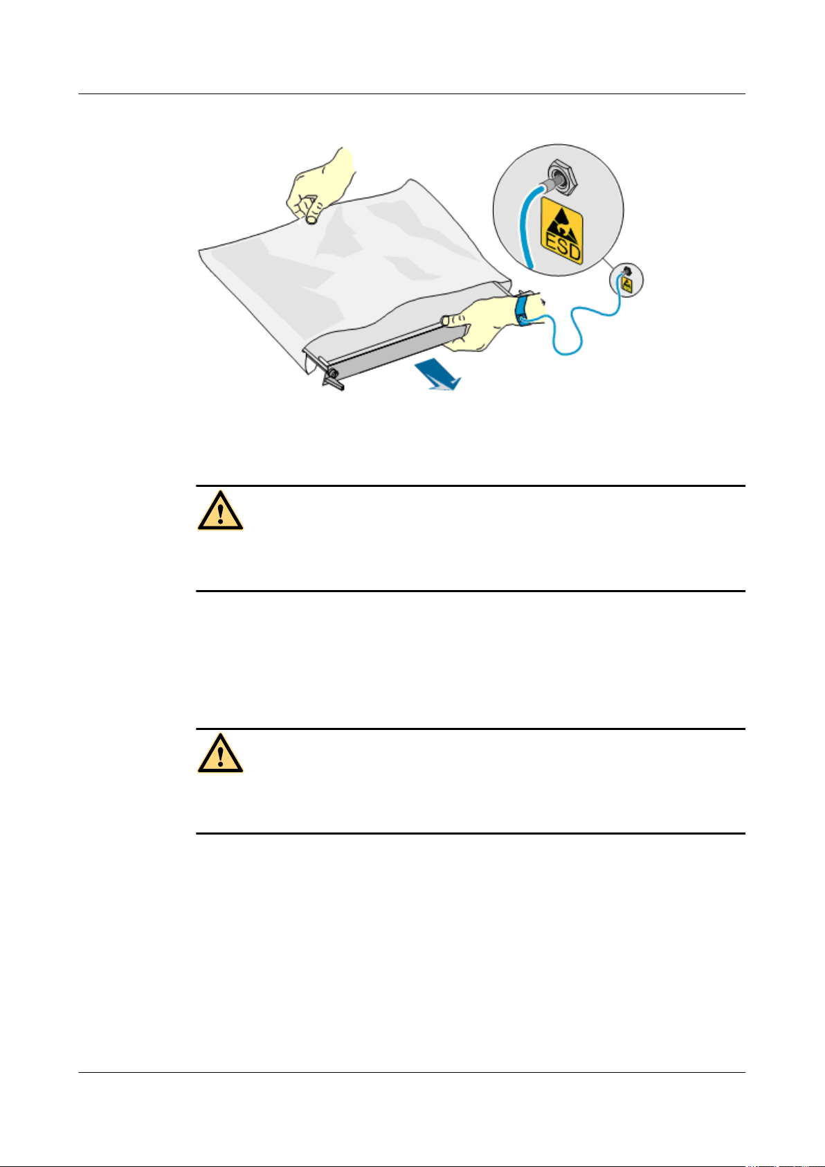
Figure 1-1 Wearing an ESD wrist strap
1.1.3 Inflammable Environment
1 RRU3606 User Guide
1.1.4 Battery
Storage Battery
DANGER
Do not place the device in the environment that has inflammable and explosive air or fog. Do
not perform any operation in this environment.
Any operation of the electrical device in the inflammable environment causes danger.
DANGER
Before handling the storage battery, read the safety precautions for the handling and connection
of the storage battery.
Incorrect operation of storage batteries may cause danger. During operation, ensure the
following:
l Prevent any short-circuit.
l Prevent the electrolyte from overflowing and leakage.
Electrolyte overflow may damage the device. It will corrode the metal parts and the circuit
boards, and ultimately damage the device and cause short-circuit of the circuit boards.
General Operations
Before installing and maintaining the storage battery, ensure the following:
Issue () Huawei Proprietary and Confidential
Copyright © Huawei Technologies Co., Ltd.
1-7
1 RRU3606 User Guide
l Use special insulation tools.
l Use eye protection devices and operate with care.
l Wear rubber gloves and an apron in case of an electrolyte overflow.
l Always keep the battery upright when moving. Do not place the battery upside down or tilt
Short-Circuit
Short-circuit of the battery may cause injury. Although the voltage of a battery is low, high
transient current generated by short-circuit will release a surge of power.
Keep metal objects away from the battery to prevent short circuit. If they have to be used,
disconnect the battery in use before performing any other operation.
Harmful Gas
it.
DANGER
l Do not use unsealed lead-acid storage batteries, because the gas emitted from it may result
in fire or device corrosion.
l Lay the storage battery horizontally and fix it properly.
The lead-acid storage battery in use will emit flammable gas. Therefore, store it in a place with
good ventilation and take precautions against fire.
High Temperature
High temperature may result in distortion, damage, and electrolyte overflow of the battery.
When the temperature of the battery exceeds 60oC, check whether there is acid overflow. If acid
overflow occurs, handle the acid immediately.
Acid
CAUTION
CAUTION
CAUTION
If the acid overflows, it should be absorbed and neutralized immediately.
1-8 Huawei Proprietary and Confidential
Copyright © Huawei Technologies Co., Ltd.
Issue ()
1 RRU3606 User Guide
When handling a leaky battery, protect against the possible damage caused by the acid. Use the
following materials to absorb and neutralize acid spills:
l Sodium bicarbonate (baking soda): NaHCO
l Sodium carbonate (soda): Na
Antacids must be used according to the instructions provided by the battery manufacturer.
Lithium Battery
There is danger of explosion if the battery is incorrectly replaced.
l Replace the lithium battery with the same or equivalent type recommended by the
l Dispose of the used battery according to the instructions provided by the manufacturer.
l Do not dispose of the lithium battery in fire.
1.1.5 Radiation
3
2CO3
CAUTION
manufacturer.
Electromagnetic Field Exposure
CAUTION
High power radio-frequency signals are harmful to human body.
Before installing or maintaining an antenna on a steel tower or mast with a large number of
transmitter antennas, the operator should coordinate with all parties to ensure that the transmitter
antennas are shut down.
The base transceiver station (BTS) has RF radiation (radiation hazard). Suggestions for the
installation and operation of BTSs are given in the following section. Operators are also required
to comply with the related local regulations on erecting BTSs.
l The antenna should be located in an area that is inaccessible to the public where the RF
radiation exceeds the stipulated value.
l If the areas where RF radiation exceeds the stipulated value are accessible to workers,
ensure that workers know where these areas are. They can shut down the transmitters before
entering these areas. Such areas may not exist; but if they exist, the areas must be within a
range of less than 10 m around the antennas.
l Each forbidden zone should be indicated by a physical barrier and striking sign to warn the
public or workers.
Issue () Huawei Proprietary and Confidential
Copyright © Huawei Technologies Co., Ltd.
1-9
1 RRU3606 User Guide
Laser
When handling optical fibers, do not stand close to, or look into the optical fiber outlet with
unaided eyes.
Laser transceivers or transmitters are used in the optical transmission system and associated test
tools. Because the laser that is transmitted through the optical fiber produces a small beam of
light, it has a very high power density and is invisible to human eyes. If a beam of light enters
the eye, the retina may be damaged.
Normally, staring into the end of an unterminated optical fiber or broken optical fiber with the
unaided eyes from a distance of more than 150 mm [5.91 in.] will not cause eye injury. Eyes
may, however, be damaged if an optical tool such as a microscope, magnifying glass or eye
loupe is used to stare into the bare optical fiber end.
Read the following guidelines to prevent laser radiation:
CAUTION
l Only the trained and authorized personnel can perform the operation.
l Wear a pair of eye-protective glasses when you are handling lasers or optical fibers.
l Ensure that the optical source is switched off before disconnecting optical fiber connectors.
l Never look into the end of an exposed optical fiber or an open connector if you cannot
ensure that the optical source is switched off.
l To ensure that the optical source is switched off, use an optical power meter.
l Before opening the front door of an optical transmission system, ensure that you are not
exposed to laser radiation.
l Never use an optical tool such as a microscope, a magnifying glass, or an eye loupe to look
into the optical fiber connector or end.
Read the following instructions before handling optical fibers:
l Only the trained personnel can cut and splice optical fibers.
l Before cutting or splicing an optical fiber, ensure that the optical fiber is disconnected from
the optical source. After disconnecting the optical fiber, use protecting caps to protect all
the optical connectors.
1.1.6 Working at Heights
CAUTION
When working at heights, ensure that the objects do not fall.
When working at heights, ensure that the following requirements must be met:
l The personnel who work at heights must be trained.
1-10 Huawei Proprietary and Confidential
Copyright © Huawei Technologies Co., Ltd.
Issue ()
l The operating machines and tools should be carried and handled safely to prevent them
l Safety measures, such as wearing a helmet and a safety belt, should be taken.
l In cold regions, warm clothes should be worn before working at heights.
l Ensure that the lifting appliances are well prepared for working at heights.
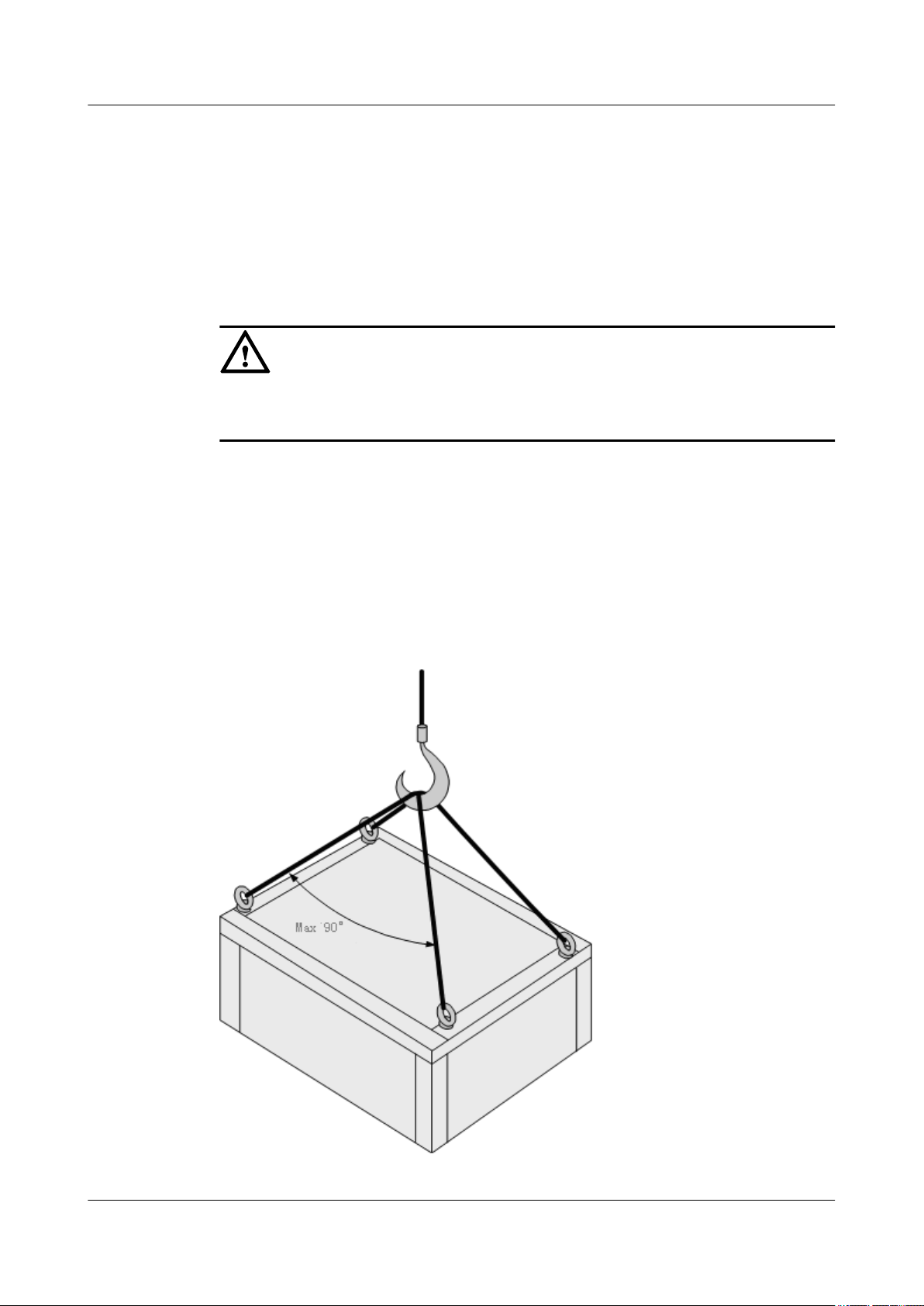
Lifting Weights
Do not access the areas under the arm of the crane and the goods in suspension when lifting
weights.
l Ensure that the operators have been trained and qualified.
l Check the weight lifting tools and ensure that they are intact.
l Lift the weight only when the weight lifting tools are firmly mounted onto the weight-
l Use a concise instruction to prevent incorrect operation.
l The angle between the two cables should be less than or equal to 90
from falling.
CAUTION
bearing object or the wall.
(See Figure 1-2).
1 RRU3606 User Guide
o
in the lifting of weights
Figure 1-2 Lifting a weight
Issue () Huawei Proprietary and Confidential
Copyright © Huawei Technologies Co., Ltd.
1-11
1 RRU3606 User Guide
Safety Guide on Ladder Use
Checking the Ladder
l Check the ladder before using it. Check the maximum weight that the ladder can support.
l Never overload the ladder.
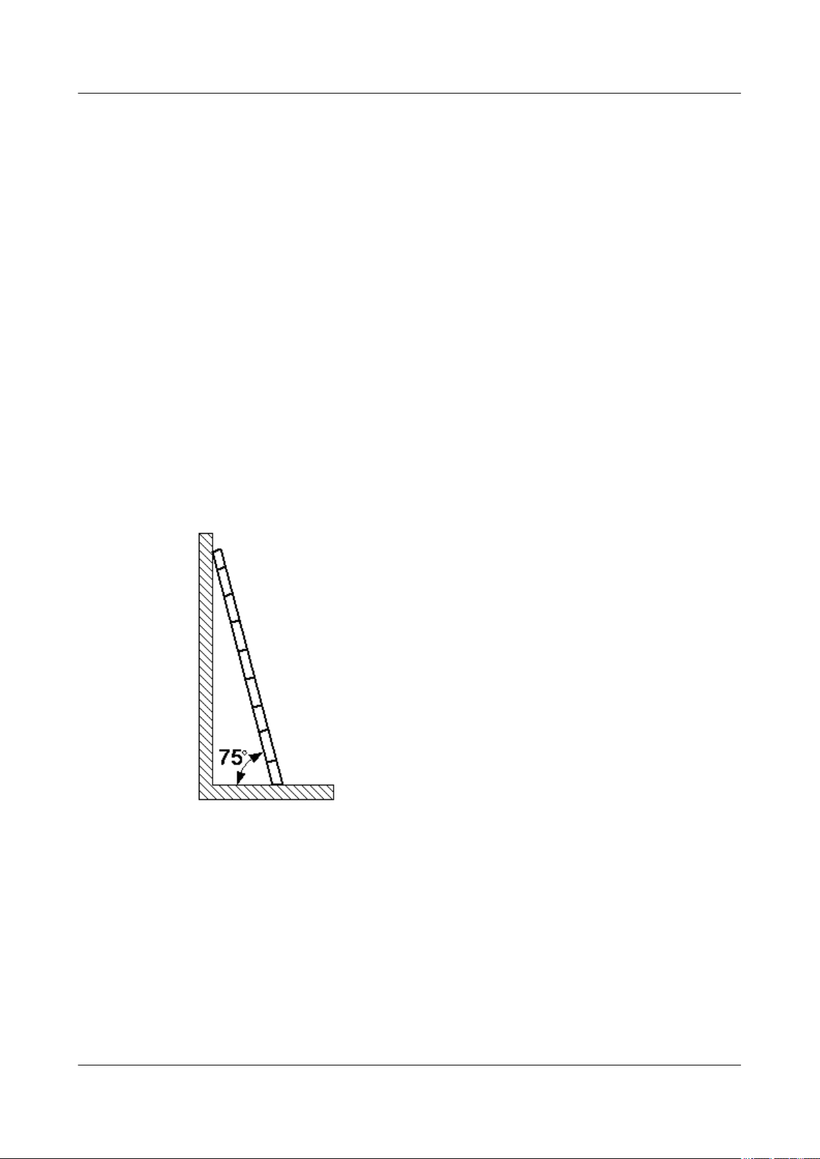
Placing the Ladder
l The slant angle is preferred to be 75
o
. The slant can be measured with the angle square or
with arms, as shown in Figure 1-3. When using a ladder, place the wider end of the ladder
on the ground and take protective measures on the base of the ladder against slippage. Place
the ladder on a stable ground.
When climbing the ladder, ensure the following:
l The gravity of the body does not shift from the edge of the ladder.
l Keep balance on the ladder before performing any operation.
l Do not climb higher than the fourth highest step of the ladder.
If you tend to climb to the roof, the length of the ladder should be at least one meter higher than
the eave, as shown in Figure 1-4.
Figure 1-3 Slant angle
1-12 Huawei Proprietary and Confidential
Copyright © Huawei Technologies Co., Ltd.
Issue ()
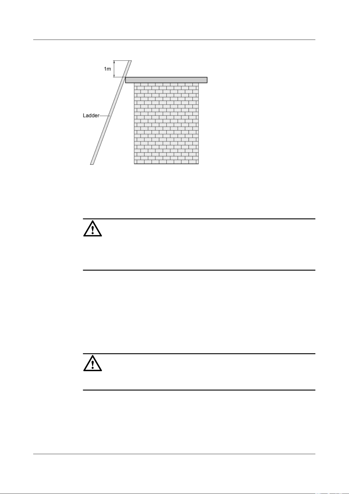
Figure 1-4 One meter higher than the eave
1.1.7 Mechanical Safety
Drilling
1 RRU3606 User Guide
CAUTION
Do not drill on the cabinet without permission. Inappropriate drilling on the cabinet may damage
the electromagnetic shielding and internal cables. Metal shavings from the drilling may result
in a short-circuit of the circuit board if they get into the cabinet.
l Before drilling a hole on the cabinet, remove the cables from the cabinet.
l During the drilling, wear blinkers to protect your eyes.
l During the drilling, wear the protective gloves.
l Prevent the metal shavings from getting into the cabinet. After drilling, clean the metal
shavings in time.
Handling Sharp Objects
CAUTION
When carrying the device by hand, wear the protective gloves to prevent injury by sharp objects.
Handling Fans
l When replacing a component, place the component, screw, and tool at a safe place to prevent
them from falling into the running fan.
l When replacing the ambient equipment around the fan, do not place the finger or board
into the running fan until the fan is switched off and stops running.
Issue () Huawei Proprietary and Confidential
Copyright © Huawei Technologies Co., Ltd.
1-13
1 RRU3606 User Guide
Moving Heavy Objects
Wear the protective gloves when moving heavy objects.
CAUTION
l Be careful when moving heavy objects.
l When moving the chassis outwards, be aware about the unfixed or heavy objects on the
chassis to prevent injury.
l Two persons should be available to move a chassis; one person must not move a heavy
chassis. When moving a chassis, keep your back straight and move stably to prevent a
sprain.
l When moving or lifting a chassis, hold the handle or bottom of the chassis. Do not hold the
handle of the installed modules in the chassis, such as the power module, fan module, or
board.
1.1.8 Others
Inserting and Removing a Board
CAUTION
When inserting a board, wear the ESD wrist strap or gloves. Insert the board gently to prevent
any bent pins on the backplane.
l Insert the board along the guide rail.
l Avoid contact of one board with another to prevent short-circuit or damage.
l Do not remove the active board before powering off.
l When holding a board in hand, do not touch the board circuit, components, connectors, or
connection slots.
Bundling Signal Cables
CAUTION
Bundle the signal cables separately from the strong current cables or high voltage cables.
Cabling Requirements
At a very low temperature, movement of the cable may damage the plastic skin of the cable. To
ensure the construction safety, comply with the following requirements:
1-14 Huawei Proprietary and Confidential
Copyright © Huawei Technologies Co., Ltd.
Issue ()

1 RRU3606 User Guide
l When installing cables, ensure that the environment temperature is above 0
l If cables are stored in the place below 0
o
C, move the cables into a place at a room
temperature and store the cables for more than 24 hours before installation.
l Move the cables with care, especially at a low temperature. Do not drop the cables directly
from the vehicle.
1.2 Hardware Configuration of the RRU3606
This describes the configuration of equipment and cables of the RRU3606.
1.2.1 RRU3606
The RRU3606 transmits and receives radio signals to realize the communication between the
wireless network and the MSs.
1.2.2 RRU3606 Cables
This describes the PGND cable, power cable, CPRI optical cable, and alarm cable of the
RRU3606.
1.2.1 RRU3606
The RRU3606 transmits and receives radio signals to realize the communication between the
wireless network and the MSs.
o
C.
The functions of the RRU3606 are described as follows:
l The RRU3606 receives RF signals from the antenna system, down-converts the signals to
IF signals, and then transmits them to the BBU3900 or the macro BTS after amplification,
analog-to-digital conversion, digital down-conversion, and matched filtering.
l The RRU3606 receives downlink baseband signals from the BBU3900 or the macro BTS,
forwards data from its cascaded RRU3606, performs filtering and data conversion, and upconverts RF signals to meet the transmitting frequency requirements.
l The RRU3606 multiplexes RX and TX signals over RF channels, enabling the RX signals
and TX signals to share the same antenna path. In addition, the RRU3606 filters the RX
signals and TX signals.
1.2.1.1 Appearance of the RRU3606
This describes the dimensions and appearance of the RRU3606.
1.2.1.2 Panels of the RRU3606
The RRU3606 has a bottom panel, cabling cavity panel, and indicator panel.
1.2.1.3 Physical Ports of the RRU3606
The physical ports of the RRU3606 are power supply ports, transmission ports, grounding ports,
and RF ports.
1.2.1.4 Technical Specifications of the RRU3606
This describes the technical specifications of the RRU3606.
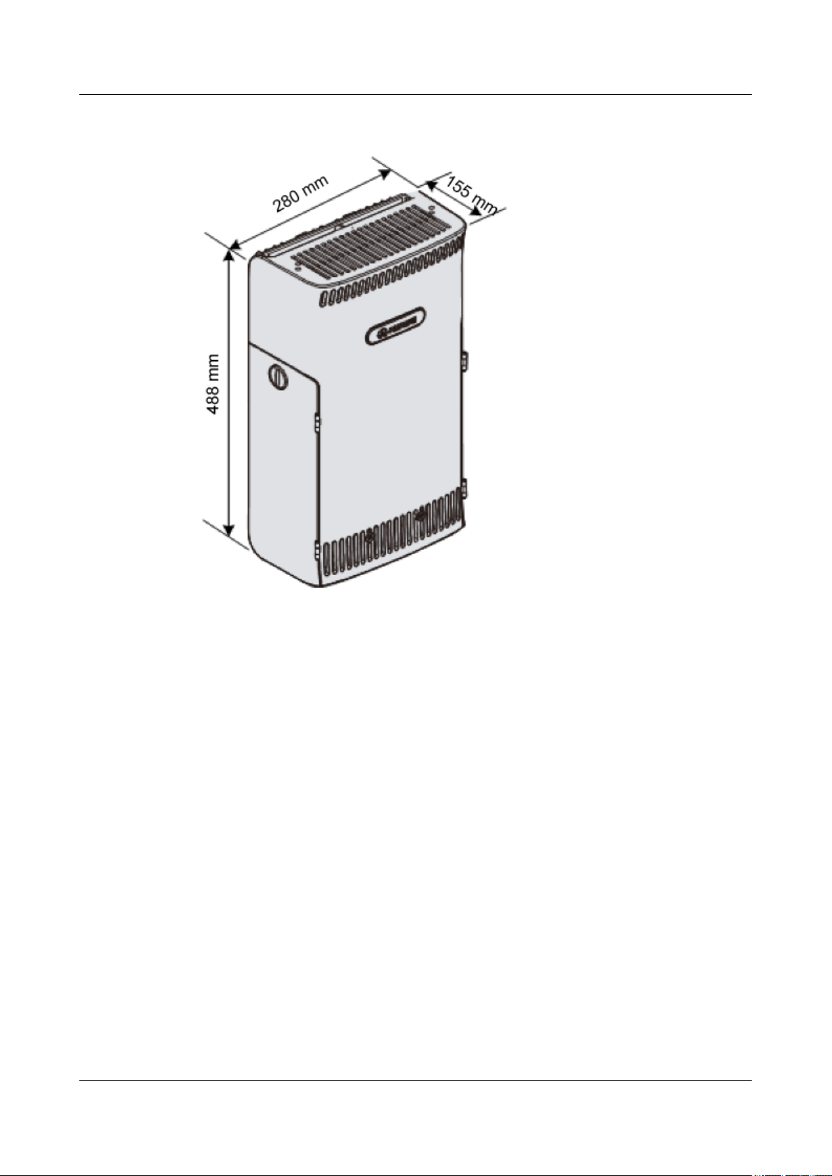
Appearance of the RRU3606
This describes the dimensions and appearance of the RRU3606.
The dimensions of the RRU3606 are as follows:
Issue () Huawei Proprietary and Confidential
Copyright © Huawei Technologies Co., Ltd.
1-15

1 RRU3606 User Guide
l Height x Width x Depth (without the housing) = 480 mm [18.90 in.] x 270 mm [10.63 in.]
l Height x Width x Depth (with the housing) = 488 mm [19.21 in.] x 280 mm [11.02 in.] x
The RRU3606 features a modular structure with its ports at the bottom of the RRU3606 and on
the cabling cavity. Figure 1-5 and Figure 1-6 shows the appearance of the RRU3606.
x 140 mm [5.51 in.]
155 mm [6.10 in.]
1-16 Huawei Proprietary and Confidential
Copyright © Huawei Technologies Co., Ltd.
Issue ()

Figure 1-5 Appearance of the RRU3606 (without the housing)
1 RRU3606 User Guide
Issue () Huawei Proprietary and Confidential
Copyright © Huawei Technologies Co., Ltd.
1-17
1 RRU3606 User Guide
Figure 1-6 Appearance of the RRU3606 (with the housing)
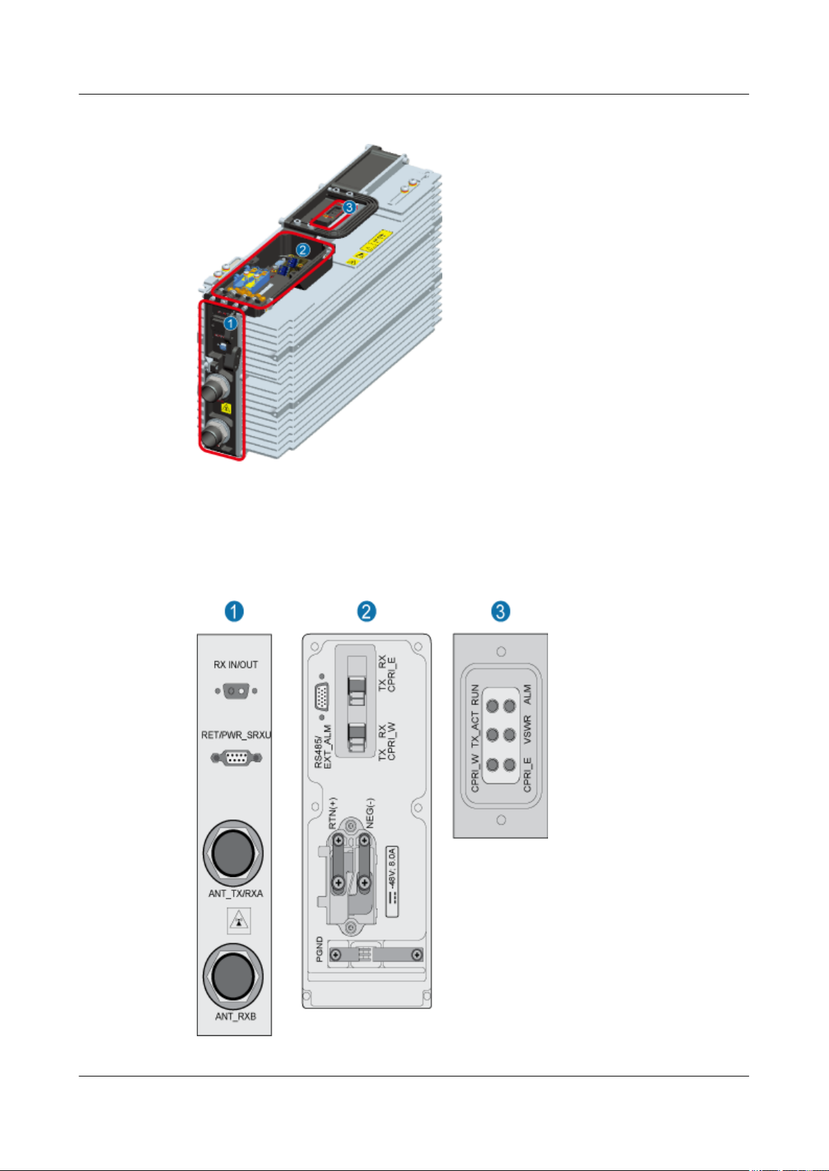
Panels of the RRU3606
The RRU3606 has a bottom panel, cabling cavity panel, and indicator panel.
Position of Panels of the RRU3606
Figure 1-7 shows the panels of the RRU3606.
1-18 Huawei Proprietary and Confidential
Copyright © Huawei Technologies Co., Ltd.
Issue ()
1 RRU3606 User Guide
Figure 1-7 Position of panels of the RRU3606
(1) Bottom (2) Cabling cavity (3) Indicator
Figure 1-8 shows the panels of the RRU3606.
Figure 1-8 Panels of the RRU3606
Issue () Huawei Proprietary and Confidential
Copyright © Huawei Technologies Co., Ltd.
1-19
1 RRU3606 User Guide
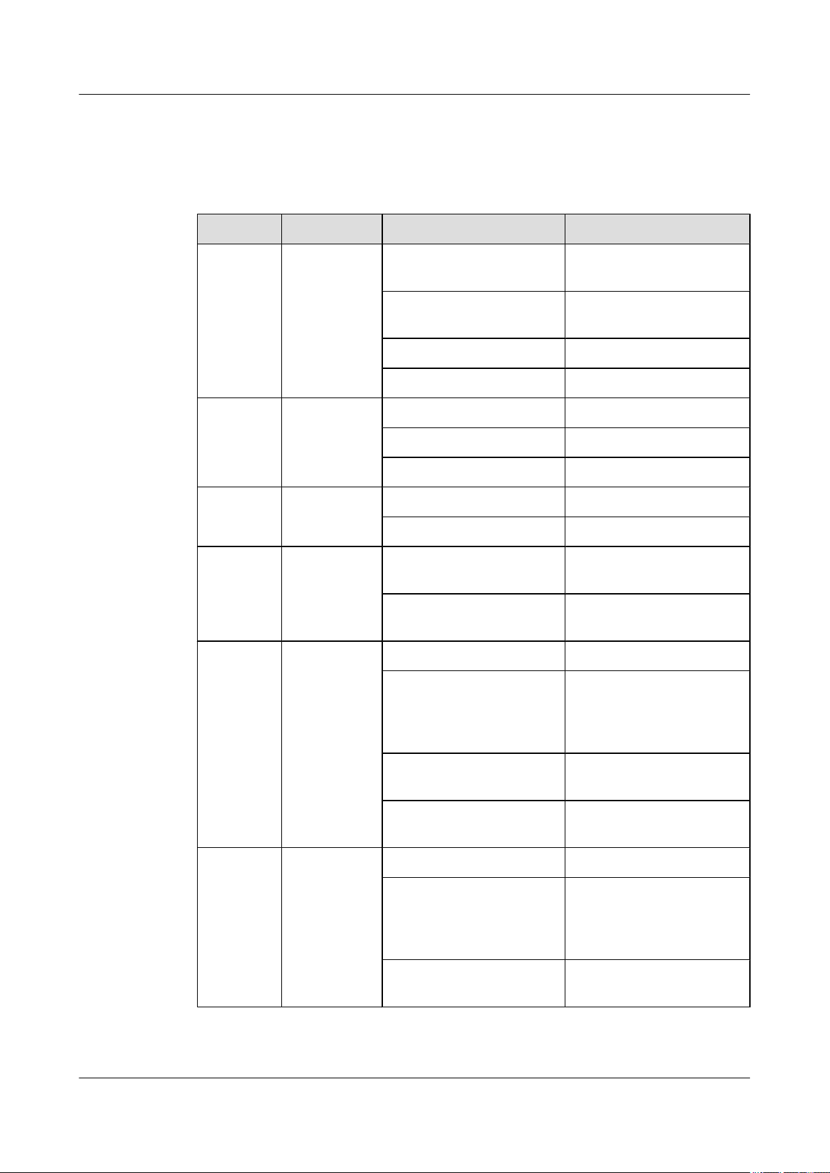
Indicators
Table 1-1 lists the indicators on the RRU3606 panel.
Table 1-1 Indicators on the RRU3606 panel
Mark Color Status Description
RUN Green ON The power input is normal,
but the board is faulty.
OFF There is no power input, or
alarms are generated.
ON for 1s and OFF for 1s The board operates normally.
ON for 0.5s and OFF for 0.5s Software is being loaded.
ALM Red ON Fatal alarms
Blinking at 0.5 Hz Minor alarms
OFF No alarm is generated.
TX_ACT Green ON The board operates normally.
OFF
VSWR Red ON Standing wave alarms are
generated.
OFF No standing wave alarm is
generated.
CPRI_W Red/green ON (green) The CPRI link is normal.
ON (red) The optical module receives
exceptional alarms, that is,
local alarms related to the
Loss of Signal (LOS).
ON for 0.5s and OFF for 0.5s
(red)
OFF The optical module is not in
CPRI_E Red/green ON (green) The CPRI link is normal.
ON (red) The optical module receives
The CPRI link is out of lock.
position or is powered off.
exceptional alarms, that is,
local alarms related to the
Loss of Signal (LOS).
ON for 0.5s and OFF for 0.5s
(red)
1-20 Huawei Proprietary and Confidential
Copyright © Huawei Technologies Co., Ltd.
The CPRI link is out of lock.
Issue ()
Ports
1 RRU3606 User Guide
Mark Color Status Description
OFF The optical module is not in
position or is powered off.
Table 1-2 lists the ports on the RRU3606 panel.
Table 1-2 Ports on the RRU3606 panel
Item Label on the Front Panel Description
Ports at the bottom RX_IN/OUT Reserved port
RET/PWR_SRXU Reserved port
ANT_TX/RXA Main RF transmitting/receiving
port
Ports on the
cabling cavity
Physical Ports of the RRU3606
The physical ports of the RRU3606 are power supply ports, transmission ports, grounding ports,
and RF ports.
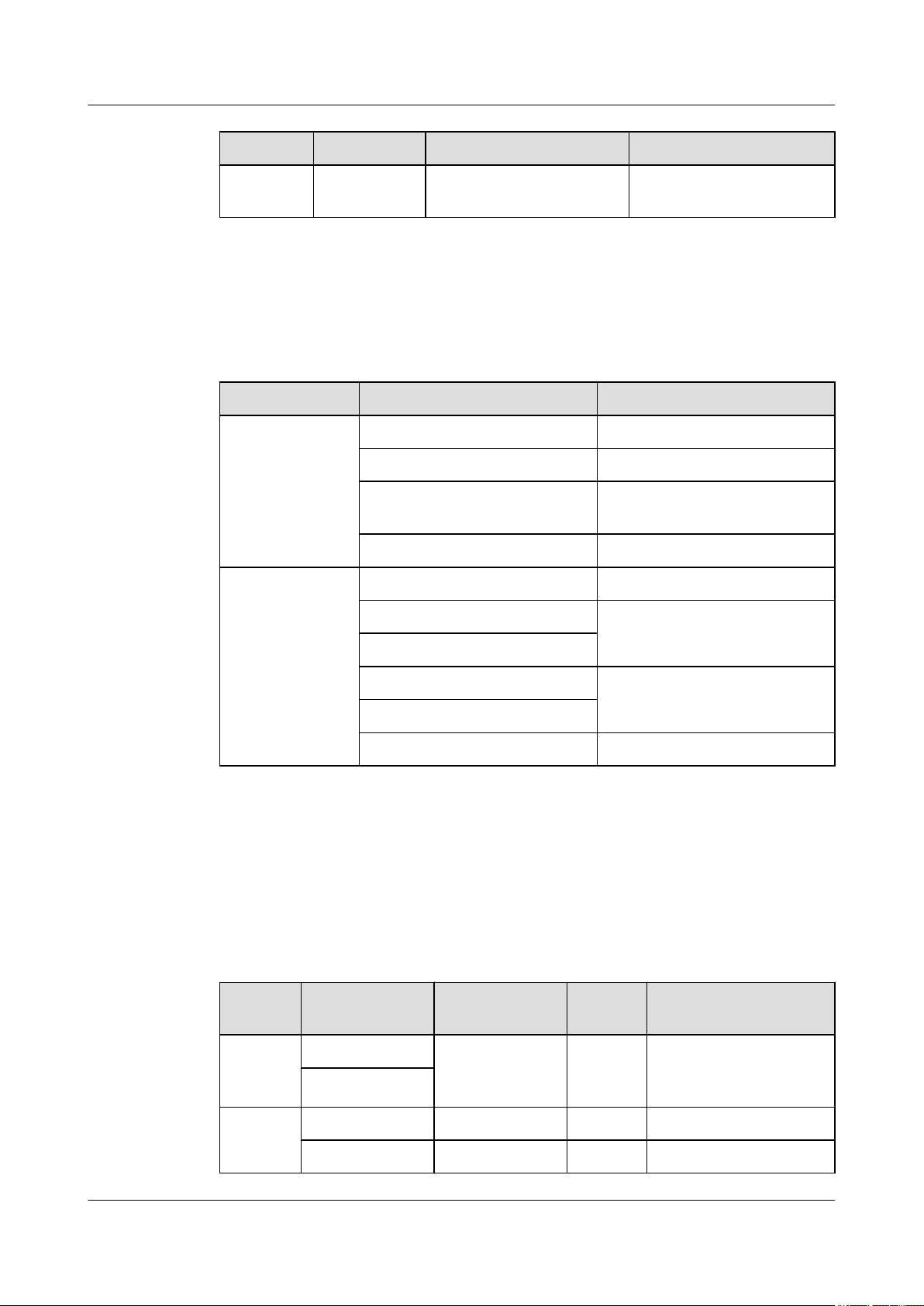
Table 1-3 lists the physical ports of the RRU3606.
Table 1-3 Physical ports of the RRU3606
Type
Port Description QuantityConnector Type
ANT_RXB Diversity RF receiving port
RS485/EXT_ALM Alarms port
CPRI_E CPRI ports
CPRI_W
RTN(+) Power supply ports
NEG(-)
PGND PGND crimp piece
Power
supply
ports
Transmis
sion ports
Issue () Huawei Proprietary and Confidential
RTN(+) -48 V DC power
supply
NEG(-)
CPRI_E CPRI ports 1 ESFP socket
CPRI_W CPRI ports 1 ESFP socket
Copyright © Huawei Technologies Co., Ltd.
1 OT terminal
1-21

1 RRU3606 User Guide
Type Port Description QuantityConnector Type
Alarms
port
Groundin
g port
RF port ANT_TX/RXA Main
Reserved
port
NOTE
The specifications for the RRU3606 alarm port are: 0.2 kohm for the closed resistance; 51 kohms for the
open resistance.
RS485/
EXT_ALM
- - 4 -
ANT_RXB Diversity
RX_IN/OUT Reserved - -
RET/
PWR_SRXU
RS485 x1 signal
port
transmitting/
receiving port
receiving port
Reserved - -
Technical Specifications of the RRU3606
1 DB15
1 Round and waterproof
DIN connector
1 Round and waterproof
DIN connector
This describes the technical specifications of the RRU3606.
Table 1-4 lists the specifications of the RRU3606.
Table 1-4 Technical specifications of the RRU3606
Item
Voltage -48 V (-37 V DC to -60 V DC)
Power consumption
Weight The weight of the RRU3606 and housing is no more
Cabinet dimensions (height x width
x depth)
1.2.2 RRU3606 Cables
This describes the PGND cable, power cable, CPRI optical cable, and alarm cable of the
RRU3606.
Specification
≤ 300 W
than 17.5 kg [38.58 lb.].
Height x Width x Depth (with the housing): 488 mm
[19.21 in.] x 280 mm [11.02 in.] x 155 mm [6.10 in.]
1.2.2.1 PGND Cable of the RRU3606
The PGND cable ensures the grounding of the RRU3606.
1-22 Huawei Proprietary and Confidential
Copyright © Huawei Technologies Co., Ltd.
Issue ()
1.2.2.2 Power Cable of the RRU3606
This describes the power cable of the RRU3606. The -48 V DC power cable feeds external -48
V DC power to the RRU3606 to provide power supply for the RRU3606.
1.2.2.3 RRU3606 Optical Fibers
RRU3606 optical fibers are used for the connection between the BBU3900 and the RRU3606.
1.2.2.4 Alarm Cable of the RRU3606
The alarm cable leads one RS485 alarm signal from external devices to the RRU3606, thus
monitoring the external devices.
PGND Cable of the RRU3606
The PGND cable ensures the grounding of the RRU3606.
Structure
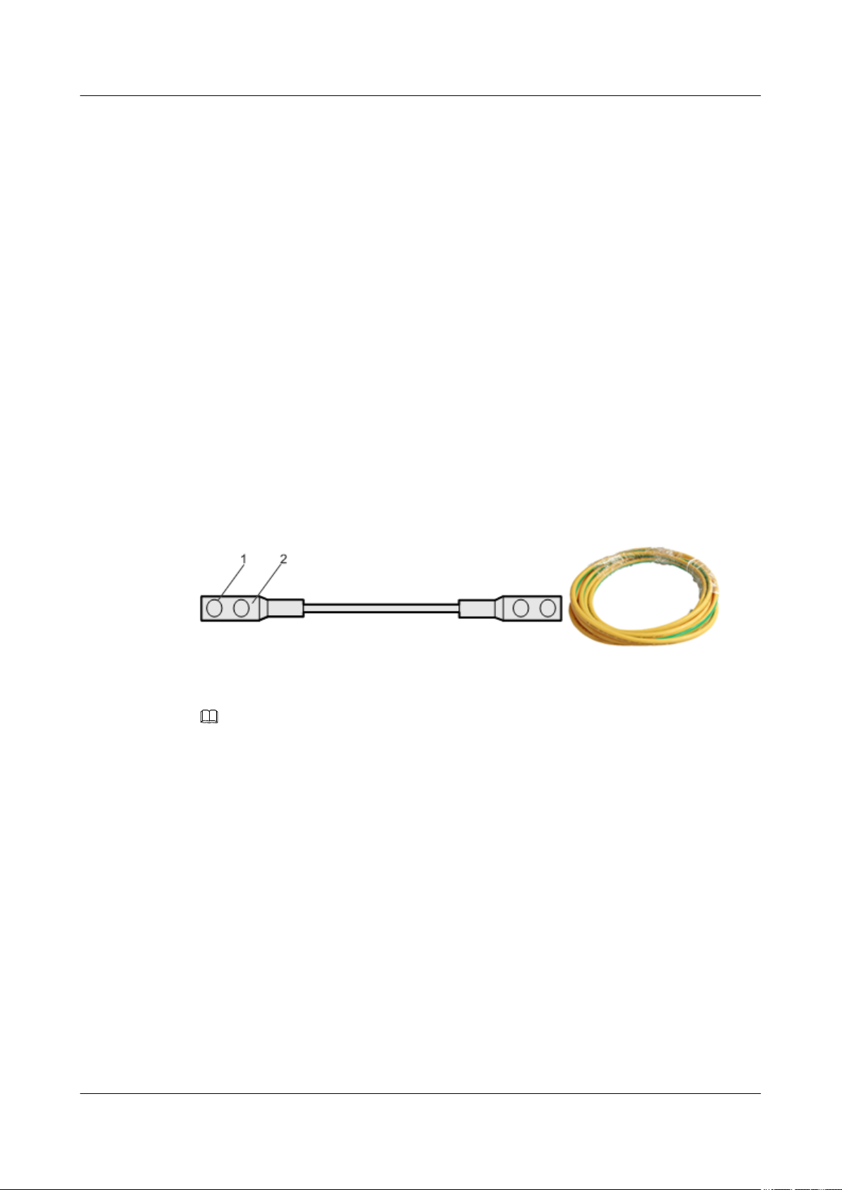
The green and yellow PGND cable has a cross-sectional area of 16 mm2 [0.02 in.2]. Both ends
of the cable are 2-hole OT terminals. If the PGND cable is provided by the customer, a copper-
core cable with a minimum cross-sectional area of 16 mm2 [0.02 in.2] is recommended.
Figure 1-9 shows the structure of the PGND cable.
1 RRU3606 User Guide
Figure 1-9 Structure of the PGND cable
(1) 2-hole OT terminal
NOTE
l The OT terminals of the grounding cable are made on site.
l The color of the PGND cable is selected according to the local specifications.
Position of the Cable
For the PGND cable of the RRU3606, one end is connected to the grounding hole on the
RRU3606, and the other end is connected to the ground nearby. Figure 1-10 shows the
connections of the PGND cables.
(2) Heat shrink tube
Issue () Huawei Proprietary and Confidential
Copyright © Huawei Technologies Co., Ltd.
1-23
1 RRU3606 User Guide
Figure 1-10 Installation position of the PGND cable
Power Cable of the RRU3606
This describes the power cable of the RRU3606. The -48 V DC power cable feeds external -48
V DC power to the RRU3606 to provide power supply for the RRU3606.
Structure
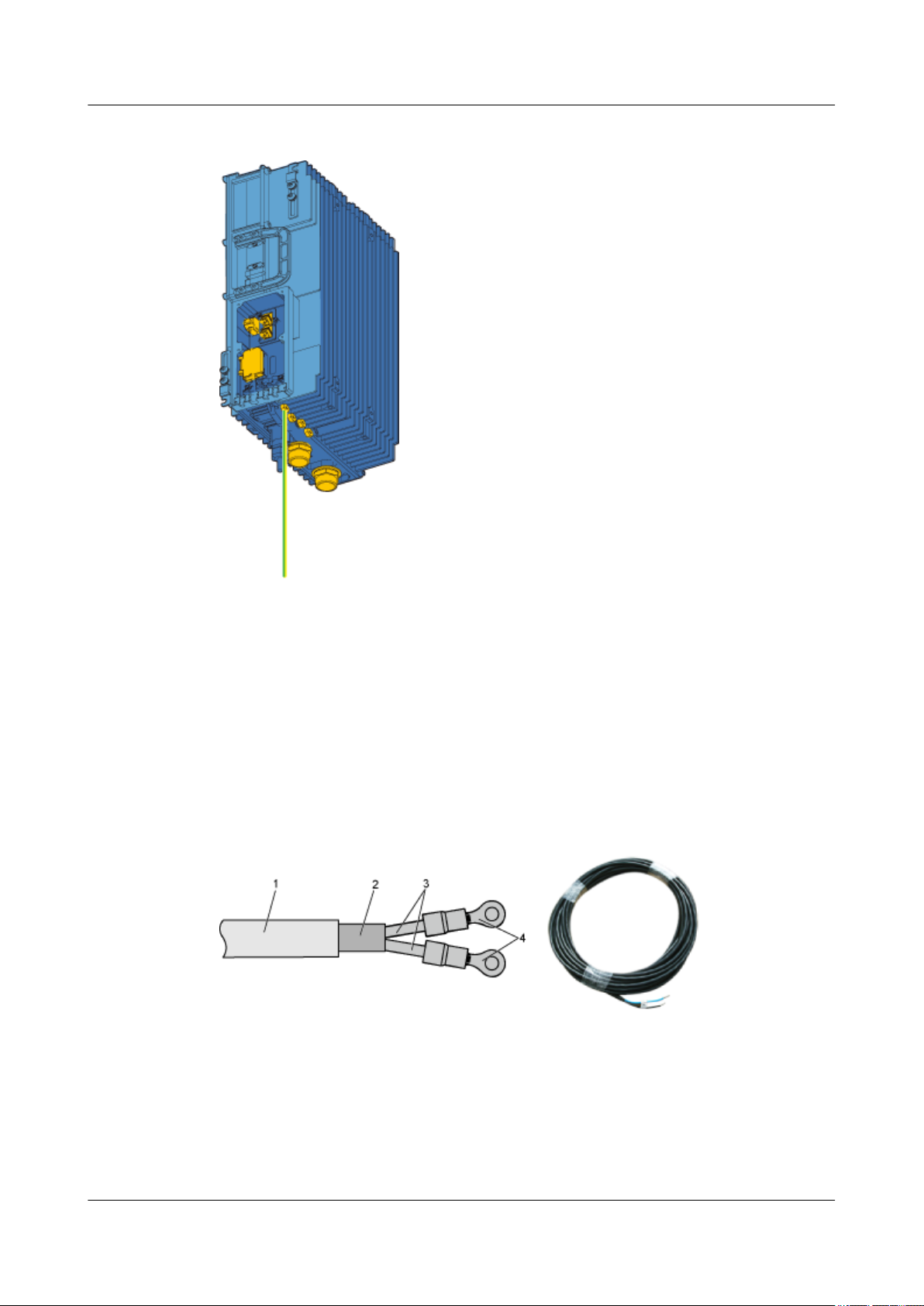
The RRU3606 uses the -48 V DC shielded power cable. One end of the cable has two OT
terminals, and the other end is bare. Figure 1-11 shows the power cable of the RRU3606.
Figure 1-11 Structure of the -48 V DC power cable
(1) -48 V DC power cable
(2) Shielding layer (3) Wire (4) OT terminal
Cable Specifications
The -48 V DC cable is a 2-wire cable, as shown in Table 1-5 and Table 1-6.
1-24 Huawei Proprietary and Confidential
Copyright © Huawei Technologies Co., Ltd.
Issue ()
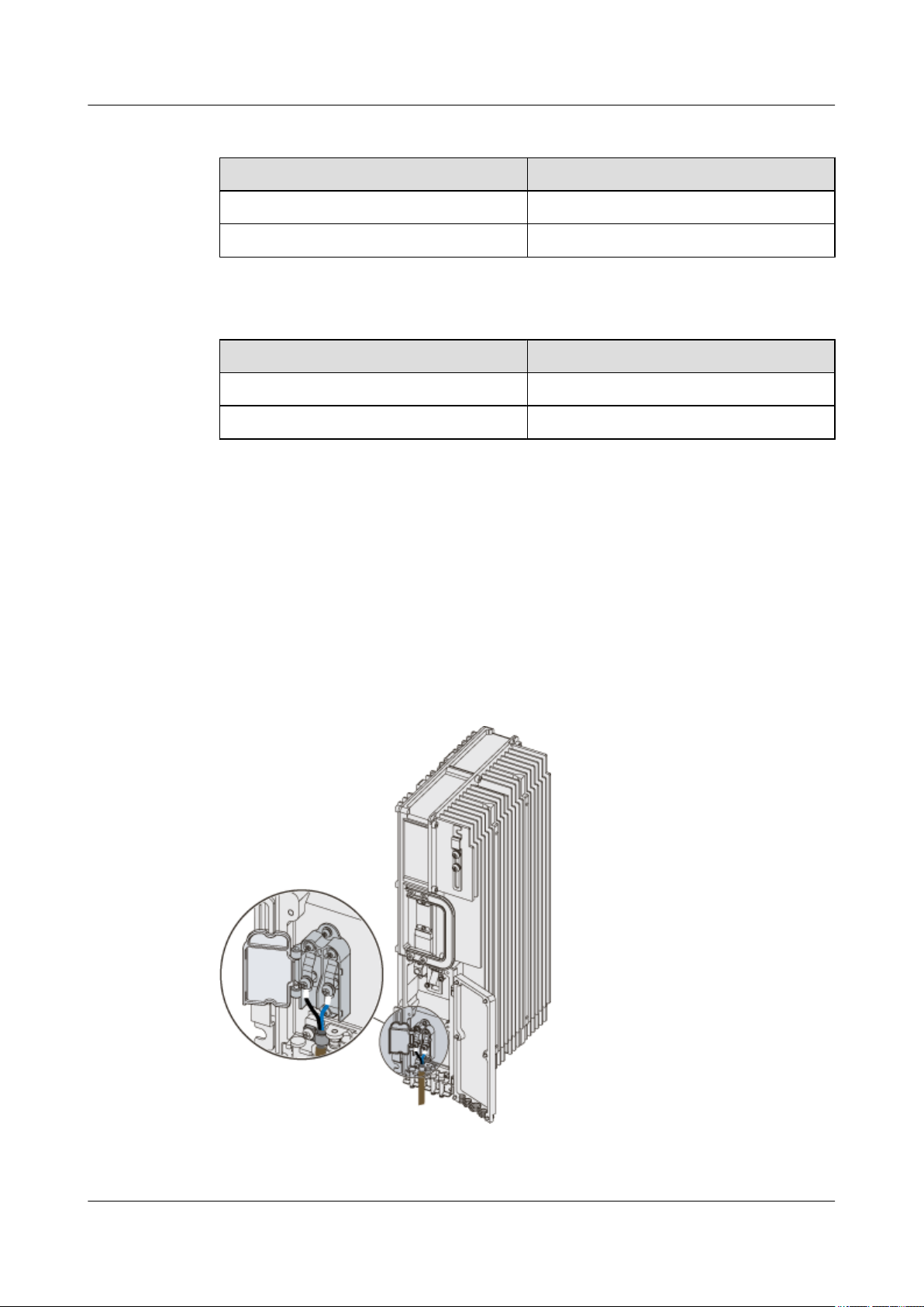
Table 1-5 Pin assignment of the -48 V DC power cable (standard in North America)
Name Color
NEG cable Blue
RTN cable Black
Table 1-6 Pin assignment of the -48 V DC power cable (standard in Europe)
Name Color
NEG cable Blue
RTN cable Brown
Position of the Cable
Connect the OT terminal of the blue wire of the -48 V DC power cable to the NEG (-) port on
the RRU3606 cabling cavity, and connect the black or brown wire to the RTN (+) port of the
RRU3606.
1 RRU3606 User Guide
Connect the other end of the -48 V DC power cable to the power supply system at the installation
site.
Figure 1-12 shows the installation position of the power cable on the RRU3606 side.
Figure 1-12 Installation of the power cable on the RRU3606 side
Issue () Huawei Proprietary and Confidential
Copyright © Huawei Technologies Co., Ltd.
1-25
1 RRU3606 User Guide
RRU3606 Optical Fibers
RRU3606 optical fibers are used for the connection between the BBU3900 and the RRU3606.
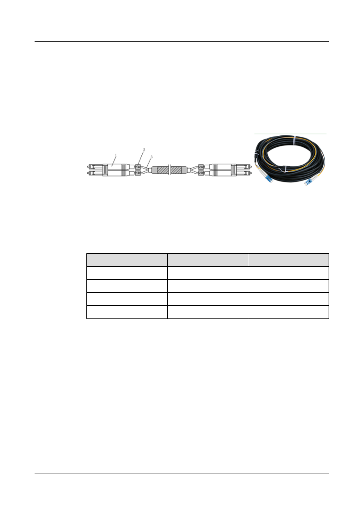
Structure
The CPRI optical cable is a multi-mode 2-wire cable with LC connectors at both ends. Figure
1-13 shows the CPRT optical fiber.
Figure 1-13 Structure of the CPRI optical fiber
(1) DLC connector (2) Label (3) Fiber tail
Cable
Table 1-7 describes the pin assignment for the fiber tails.
Table 1-7 Pin assignment for the fiber tails
Label
1A Orange RX port on the RRU3606
1B Gray TX port on the RRU3606
2A Orange TX port on the BBU3900
2B Gray RX port on the BBU3900
Position of the Cable
One end of the CPRI optical fiber is connected to the SFP port of the BBU3900 or to the ODF,
and the other end is connected to the CPRI optical port of the RRU3606. Figure 1-14 shows the
installation position of the CPRI optical fiber on the RRU3606 side.
Color Connection Position
1-26 Huawei Proprietary and Confidential
Copyright © Huawei Technologies Co., Ltd.
Issue ()
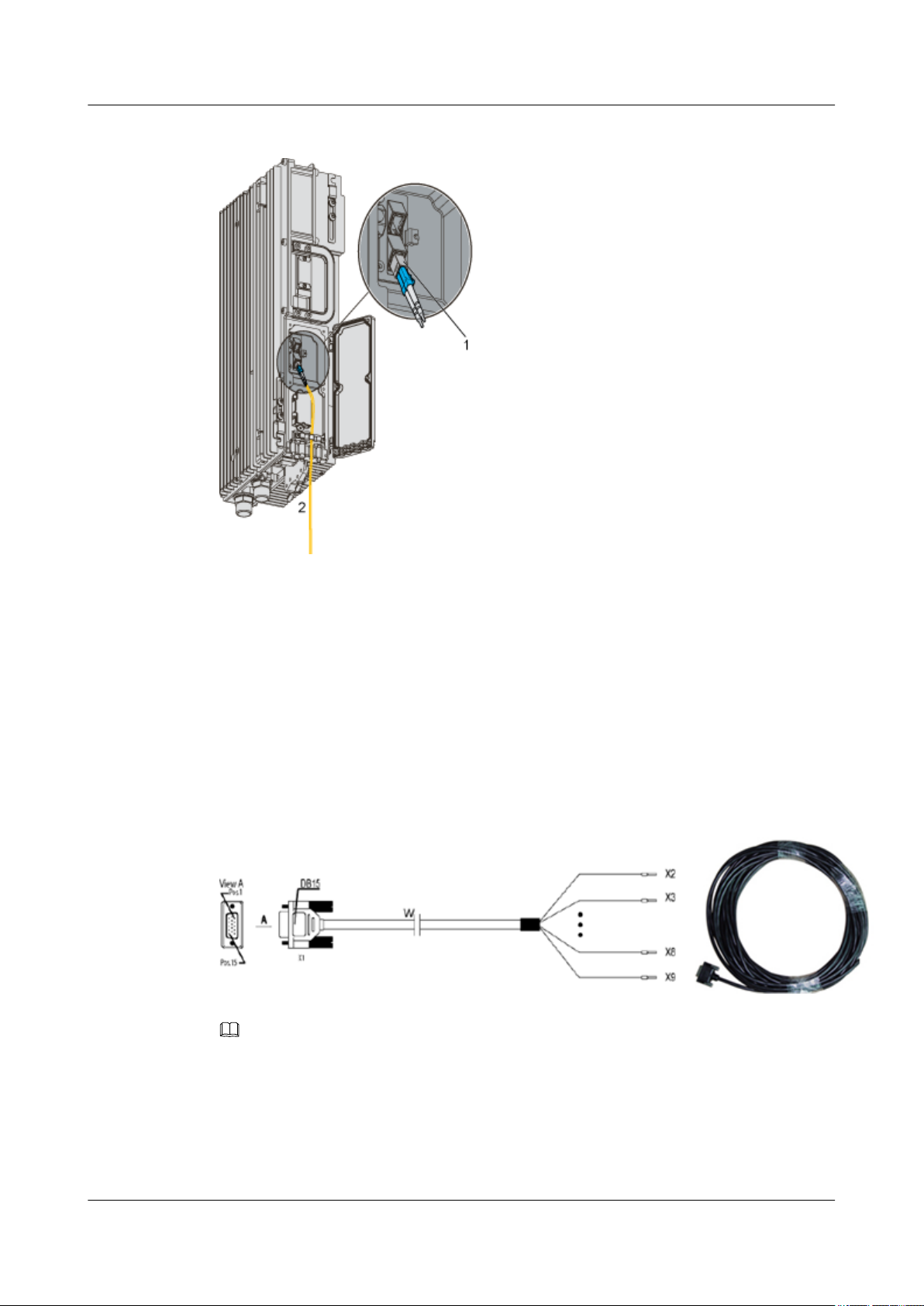
Figure 1-14 Structure of the CPRI optical cable
1 RRU3606 User Guide
(1) Pluggable optical modules (2) To the BBU3900 or the ODF
Alarm Cable of the RRU3606
The alarm cable leads one RS485 alarm signal from external devices to the RRU3606, thus
monitoring the external devices.
Structure
One end of the alarm cable is a DB15 female connector, and the other end has 8 cord end
terminals, as shown in Figure 1-15.
Figure 1-15 Structure of the alarm cable of the RRU3606
NOTE
If the connector of the alarm cable and the port of the alarm device do not match, remove the cord end
terminals. Prepare the connector on site based on the port type of the alarm device.
Cable
The alarm cable supports one RS485 alarm signal. Table 1-8 lists the pin assignment for the
wires of the RRU3606.
Issue () Huawei Proprietary and Confidential
Copyright © Huawei Technologies Co., Ltd.
1-27
1 RRU3606 User Guide
Table 1-8 Alarm cable of the RRU3606
X1 Pin Cord End
X1.2 X2 White/blue Twisted pair
X1.3 X3 Blue GND
X1.6 X4 White/orange Twisted pair
X1.7 X5 Orange GND
X1.10 X6 White/green Twisted pair
X1.11 X7 Green RS485_TX+
X1.13 X8 White/brown Twisted pair
X1.14 X9 Brown RS485_RX+
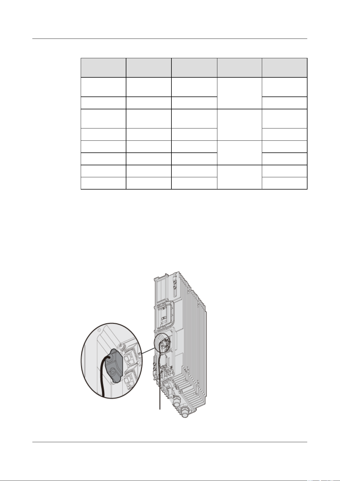
Position of the Cable
The DB15 male connector of the alarm cable is connected to the RS485/EXT_ALM port on the
RRU3606 cabling cavity, and the other end is connected to the port for Boolean alarm signals
on the external device. Figure 1-16 shows the installation position of the alarm cable on the
RRU3606 side.
Terminal
Wire Color Wire Type Label
SWITCH_INP
cable
cable
cable
cable
UT0+
SWITCH_INP
UT1+
RS485_TX-
RS485_RX-
Figure 1-16 Installation of the alarm cable on the RRU3606 side
1-28 Huawei Proprietary and Confidential
Copyright © Huawei Technologies Co., Ltd.
Issue ()
 Loading...