

Huawei RRU3232-3650 Users Guide

DBS3900(ICR)
Installation Guide
Issue 01
Date 2011-03-30
HUAWEI TECHNOLOGIES CO., LTD.


Copyright © Huawei Technologies Co., Ltd. 2011. All rights reserved.
No part of this document may be reproduced or transmitted in any form or by any means without prior written
consent of Huawei Technologies Co., Ltd.
Trademarks and Permissions
and other Huawei trademarks are trademarks of Huawei Technologies Co., Ltd.
All other trademarks and trade names mentioned in this document are the property of their respective holders.
Notice
The purchased products, services and features are stipulated by the contract made between Huawei and the
customer. All or part of the products, services and features described in this document may not be within the
purchase scope or the usage scope. Unless otherwise specified in the contract, all statements, information,
recommendations in this document are provided "AS IS" without warranties, guarantees or representations
and
of any kind, either express or implied.
The information in this document is subject to change without notice. Every effort has been made in the
preparation of this document to ensure accuracy of the contents, but all statements, information, and
recommendations in this document do not constitute the warranty of any kind, express or implied.
Huawei Technologies Co., Ltd.
Address: Huawei Industrial Base
Bantian, Longgang
Shenzhen 518129
People's Republic of China
Website:
Email: support@huawei.com
http://www.huawei.com
Issue 01 (2011-03-30) Huawei Proprietary and Confidential
Copyright © Huawei Technologies Co., Ltd.
i


DBS3900(ICR)
Installation Guide About This Document
About This Document
Purpose
This document describes the procedures for installing the DBS3900 devices on the Indoor
Centralized Rack (ICR).
Product Version
The following table lists the product versions related to this document.
Product Name Product Version
DBS3900 V100R004
DBS3900 WCDMA V200R013
DBS3900 LTE V100R003C00
DBS3900 GSM V100R013
Intended Audience
This document is intended for:
l Base station installation engineers
Organization
1 Changes in the DBS3900 (ICR) Installation Guide
2 Installation Preparations
This chapter describes the tools and instruments required for installation and the skills and
prerequisites required for onsite installation engineers.
Issue 01 (2011-03-30) Huawei Proprietary and Confidential
Copyright © Huawei Technologies Co., Ltd.
iii

About This Document
DBS3900(ICR)
Installation Guide
3 Information About the Installation
This chapter describes the information about the installation, including exterior, installation
scenario, and space requirements
4 Unpacking the Equipment
Unpack
and check the delivered equipment to ensure that all the materials are included and intact.
5 Obtaining the ESN
The Electronic Serial Number (ESN) is a unique identifier of a Network Element (NE). Record
the ESN for later commissioning of the base station before installation.
6 Installation Process
This section describes the process of installing the DBS39000 on the ICR.
7 Assembling the IFS06
This chapter describes the procedure for assembling the IFS06.
8 Installing the IFS06
This chapter describes the procedure for installing the IFS06 on the concrete floor and ESD
floor.
9 Installing the Main Bracket for the RRU
This chapter describes the procedure for installing the main bracket for the DC RRU and AC
RRU.
10 Installing the GPS Surge Protector
This chapter describes the procedure for installing the GPS surge protector.
11 Installing the IMB03
This chapter describes the procedure for installing the IMB03.
12 Installing the Equipotential Cable and PGND Cable
This chapter describes the procedures for installing the equipotential cable and PGND cable.
13 Installing Devices in the IMB03
This chapter describes the installation of the devices in the IMB03.
14 Installing the RRU
This section describes the procedure for installing the AC RRU and DC RRU.
15 Installing Cables
This chapter describes the procedure for installing all the cables.
16 Checklist for the DBS3900 Hardware Installation
This section describes the checklist for the DBS3900 hardware installation.
17 Performing the DBS3900 Power-On Check
After all devices are installed, you need to check the power-on status of the BBU and RRU.
18 Installing the Cover Plate for the IMB03
iv Huawei Proprietary and Confidential
Copyright © Huawei Technologies Co., Ltd.
Issue 01 (2011-03-30)
DBS3900(ICR)
Installation Guide About This Document
This section describes the procedure for installing the cover plate for the IMB03.
Conventions
Symbol Conventions
The symbols that may be found in this document are defined as follows.
Symbol Description
Indicates a hazard with a high level of risk, which if not
avoided, will result in death or serious injury.
Indicates a hazard with a medium or low level of risk, which
if not avoided, could result in minor or moderate injury.
Indicates a potentially hazardous situation, which if not
avoided, could result in equipment damage, data loss,
performance degradation, or unexpected results.
Indicates a tip that may help you solve a problem or save
time.
Provides additional information to emphasize or supplement
important points of the main text.
General Conventions
The general conventions that may be found in this document are defined as follows.
Convention Description
Times New Roman Normal paragraphs are in Times New Roman.
Boldface Names of files, directories, folders, and users are in
boldface. For example, log in as user root.
Italic Book titles are in italics.
Courier New
Examples of information displayed on the screen are in
Courier New.
Command Conventions
The command conventions that may be found in this document are defined as follows.
Convention Description
Boldface The keywords of a command line are in boldface.
Italic Command arguments are in italics.
Issue 01 (2011-03-30) Huawei Proprietary and Confidential
Copyright © Huawei Technologies Co., Ltd.
v

About This Document
DBS3900(ICR)
Installation Guide
Convention Description
[ ] Items (keywords or arguments) in brackets [ ] are optional.
{ x | y | ... } Optional items are grouped in braces and separated by
vertical bars. One item is selected.
[ x | y | ... ] Optional items are grouped in brackets and separated by
vertical bars. One item is selected or no item is selected.
{ x | y | ... }
*
Optional items are grouped in braces and separated by
vertical bars. A minimum of one item or a maximum of all
items can be selected.
[ x | y | ... ]
*
Optional items are grouped in brackets and separated by
vertical bars. Several items or no item can be selected.
GUI Conventions
The GUI conventions that may be found in this document are defined as follows.
Convention Description
Boldface Buttons, menus, parameters, tabs, window, and dialog titles
are in boldface. For example, click OK.
> Multi-level menus are in boldface and separated by the ">"
signs. For example, choose File > Create > Folder.
Keyboard Operations
The keyboard operations that may be found in this document are defined as follows.
Format Description
Key Press the key. For example, press Enter and press Tab.
Key 1+Key 2 Press the keys concurrently. For example, pressing Ctrl+Alt
+A means the three keys should be pressed concurrently.
Key 1, Key 2 Press the keys in turn. For example, pressing Alt, A means
the two keys should be pressed in turn.
Mouse Operations
The mouse operations that may be found in this document are defined as follows.
vi Huawei Proprietary and Confidential
Copyright © Huawei Technologies Co., Ltd.
Issue 01 (2011-03-30)

DBS3900(ICR)
Installation Guide About This Document
Action Description
Click Select and release the primary mouse button without moving
the pointer.
Double-click Press the primary mouse button twice continuously and
quickly without moving the pointer.
Drag Press and hold the primary mouse button and move the
pointer to a certain position.
Issue 01 (2011-03-30) Huawei Proprietary and Confidential
Copyright © Huawei Technologies Co., Ltd.
vii


DBS3900(ICR)
Installation Guide Contents
Contents
About This Document...................................................................................................................iii
1 Changes in the DBS3900 (ICR) Installation Guide.............................................................1-1
2 Installation Preparations...........................................................................................................2-1
2.1 Making Documents Available.........................................................................................................................2-2
2.2 Tools and Instruments.....................................................................................................................................2-2
2.3 Skills and Requirements for Onsite Personnel................................................................................................2-3
3 Information About the Installation........................................................................................3-1
3.1 Overview of Devices.......................................................................................................................................3-2
3.2 Installation Options.........................................................................................................................................3-5
3.2.1 Height-Restricted Scenario.................................................................................................................... 3-5
3.2.2 Height-Unrestricted Scenario...............................................................................................................3-17
3.3 Dimensions and Installation Clearance Requirements..................................................................................3-35
4 Unpacking the Equipment.......................................................................................................4-1
5 Obtaining the ESN.....................................................................................................................5-1
6 Installation Process....................................................................................................................6-1
7 Assembling the IFS06................................................................................................................7-1
8 Installing the IFS06....................................................................................................................8-1
8.1 Installing the IFS06 on the Concrete Floor.....................................................................................................8-2
8.2 Installing the IFS06 on the ESD Floor............................................................................................................8-6
9 Installing the Main Bracket for the RRU...............................................................................9-1
9.1 Installing the Main Bracket for the DC RRU..................................................................................................9-2
9.2 Installing the Main Bracket for the AC RRU..................................................................................................9-3
10 Installing the GPS Surge Protector.....................................................................................10-1
11 Installing the IMB03..............................................................................................................11-1
11.1 Installing the IMB03 on the Upper Level Separately
11.2 Installing the IMB03 on the Lower Level Separately.................................................................................11-3
11.3 Installing the IMB03s on the Upper and Lower Levels..............................................................................11-5
..................................................................................11-2
12 Installing the Equipotential Cable and PGND Cable....................................................12-1
Issue 01 (2011-03-30) Huawei Proprietary and Confidential
Copyright © Huawei Technologies Co., Ltd.
ix

DBS3900(ICR)
Contents
Installation Guide
13 Installing Devices in the IMB03..........................................................................................13-1
13.1 Installing the BBU.......................................................................................................................................13-2
13.2 Installing the DCDU-03B............................................................................................................................
13.3 (Optional) Installing the Power Equipment (DC/DC).................................................................................13-4
13.4 (Optional) Installing the Power Equipment (AC/DC).................................................................................13-6
13-3
14 Installing the RRU.................................................................................................................14-1
14.1 Installing the DC RRU................................................................................................................................14-2
14.2 Installing the AC RRU................................................................................................................................14-5
15 Installing Cables.....................................................................................................................15-1
15.1 Cabling Requirements.................................................................................................................................15-3
15.2 Cable Connections.......................................................................................................................................15-4
15.2.1 Cable Connections (-48 V DC, Six RRU3008s)................................................................................15-5
15.2.2 Cable Connections (-48 V DC, Six RRU3804s)................................................................................15-7
15.2.3 Cable Connections (-48 V DC, Six RRU3201s)................................................................................15-8
15.2.4 Cable Connections (-48 V DC, Six RRU3908s)..............................................................................15-10
15.2.5 Cable Connections (-48 V DC, Three RRU3908s+Three RRU3804s)............................................15-12
15.2.6 Cable Connections (-48 V DC, Three RRU3008s+Three RRU3804s)............................................15-16
15.2.7 Cable Connections (-48 V, Three RRU3908s + Three RRU3201s)................................................15-18
15.2.8 Cable Connections (-48 V DC, Three RRU3008s+Three RRU3201s)............................................15-22
15.2.9 Cable Connections (-48 V DC, Three RRU3804s+Three RRU3201s)............................................15-24
15.2.10 Cable Connections (-48 V DC, Six RRU3008s+Six RRU3804s)..................................................15-26
15.2.11 Cable Connections (-48 V DC, Six RRU3908s+Six RRU3804s)..................................................15-28
15.2.12 Cable Connections (-48 V DC, Six RRU3908s+Six RRU3201s)..................................................15-33
15.2.13 Cable Connections (-48 V DC, Six RRU3008s+Six RRU3201s)..................................................15-39
15.2.14 Cable Connections (-48 V DC, Six RRU3804s+Six RRU3201s)..................................................15-41
15.2.15 Cable Connections (AC RRU).......................................................................................................15-43
15.2.16 Cable Connections (220 V AC).....................................................................................................15-44
15.2.17 Cable Connections (+24 V DC).....................................................................................................15-45
15.3 Cable Installation Process.........................................................................................................................15-46
15.4 Cable Routes.............................................................................................................................................15-47
15.5 Installing the PGND Cable for the RRU...................................................................................................15-48
15.6 Installing the Power Cable for the BBU....................................................................................................15-50
15.7 Installing the Input Power Cable...............................................................................................................15-51
15.8 (Optional) Installing the Power Cable and Monitoring Signal Cable for the DCDU...............................15-54
15.9 Installing the Power Cable for the RRU....................................................................................................15-56
15.10 Installing the E1/T1 Cable (FE/GE Cable or FE/GE Optical Cable)......................................................15-59
15.11 Installing the CPRI Optical Cable...........................................................................................................15-61
15.12 Installing the Antenna Jumper for the RRU............................................................................................15-64
15.13 Installing a GPS Clock Signal Cable.......................................................................................................15-67
16 Checklist for the DBS3900 Hardware Installation...........................................................16-1
17 Performing the DBS3900 Power-On Check......................................................................17-1
x Huawei Proprietary and Confidential
Copyright © Huawei Technologies Co., Ltd.
Issue 01 (2011-03-30)

DBS3900(ICR)
Installation Guide Contents
18 Installing the Cover Plate for the IMB03...........................................................................18-1
Issue 01 (2011-03-30) Huawei Proprietary and Confidential
Copyright © Huawei Technologies Co., Ltd.
xi


DBS3900(ICR)
Installation Guide Figures
Figures
Figure 3-1 DCDU-03B.........................................................................................................................................3-3
Figure 3-2 BBU3900............................................................................................................................................3-3
Figure 3-3 RRU....................................................................................................................................................3-4
Figure 3-4 Power equipment (AC/DC)................................................................................................................3-4
Figure 3-5 Power equipment (DC/DC)................................................................................................................3-5
Figure 3-6 Height-restricted scenario...................................................................................................................3-6
Figure 3-7 Height-restricted scenario (-48 V DC)...............................................................................................3-7
Figure 3-8 Height-restricted scenario (-48 V DC)...............................................................................................3-8
Figure 3-9 Height-restricted scenario (-48 V DC)...............................................................................................3-9
Figure 3-10 Installation of the DC RRUs on the IFS06.....................................................................................3-10
Figure 3-11 Height-restricted scenario (220 V AC)...........................................................................................3-11
Figure 3-12 Height-restricted scenario (220 V AC)...........................................................................................3-12
Figure 3-13 Installation of the DC RRU on the IFS06.......................................................................................
Figure 3-14 Installation of AC RRUs on the IFS06...........................................................................................3-14
Figure 3-15 Height-restricted scenario (+24 V DC)..........................................................................................3-15
Figure 3-16 Height-restricted scenario (+24 V DC)..........................................................................................3-16
Figure 3-17 Installation of the DC RRUs on the IFS06.....................................................................................3-17
Figure 3-18 Height-unrestricted scenario...........................................................................................................3-18
Figure 3-19 Height-unrestricted scenario (-48 V DC).......................................................................................3-19
Figure 3-20 Height-unrestricted scenario (-48 V DC).......................................................................................3-20
Figure 3-21 Height-unrestricted triple-mode scenario (-48 V DC)....................................................................3-21
Figure 3-22 Height-unrestricted scenario (-48 V DC).......................................................................................3-22
Figure 3-23 Height-unrestricted triple-mode scenario (-48 V DC)....................................................................3-23
Figure 3-24 Installation of the DC RRUs on the IFS06.....................................................................................3-24
Figure 3-25 Height-unrestricted scenario (220 V AC).......................................................................................3-25
Figure 3-26 Height-unrestricted scenario (220 V AC).......................................................................................3-26
Figure 3-27 Height-unrestricted scenario (220 V AC).......................................................................................3-27
Figure 3-28 Height-unrestricted triple-mode scenario (220 V AC)...................................................................3-28
Figure 3-29 Installation of the DC RRUs on the IFS06.....................................................................................3-29
Figure 3-30 Installation of AC RRUs on the IFS06...........................................................................................3-30
Figure 3-31 Height-unrestricted scenario (+24 V DC)......................................................................................3-31
Figure 3-32 Height-unrestricted scenario (+24 V DC)......................................................................................3-32
Figure 3-33 Height-unrestricted scenario (+24 V DC)......................................................................................3-33
3-13
Issue 01 (2011-03-30) Huawei Proprietary and Confidential
Copyright © Huawei Technologies Co., Ltd.
xiii

Figures
DBS3900(ICR)
Installation Guide
Figure 3-34 Height-unrestricted triple-mode scenario (+24 V DC)...................................................................3-34
Figure 3-35 Installation of the DC RRUs on the IFS06.....................................................................................3-35
Figure 3-36 Dimensions of the IFS06................................................................................................................3-36
Figure 3-37 Dimensions of the IMB03..............................................................................................................
Figure 3-38 Recommended clearance for the ICR (DC-RRU-based)................................................................3-37
Figure 3-39 Recommended clearance for the ICR (AC-RRU-based)................................................................3-38
Figure 3-40 Minimum clearance for the ICR in the height-unrestricted scenario............................................. 3-39
Figure 3-41 Minimum clearance for the ICR in the height-restricted scenario................................................. 3-40
Figure 3-42 Minimum clearance for the ICR (AC-RRU-based)........................................................................3-41
Figure 3-43 Clearance requirements for combined cabinets..............................................................................3-42
Figure 5-1 Obtaining the ESN (1)........................................................................................................................5-1
Figure 5-2 Obtaining the ESN (2)........................................................................................................................5-2
Figure 6-1 Installation process.............................................................................................................................6-2
Figure 7-1 Installing the rear feet.........................................................................................................................7-1
Figure 7-2 Installing the front feet.......................................................................................................................7-2
Figure 7-3 Moving down the adjustable beam.....................................................................................................7-3
Figure 7-4 Installing the cable rack......................................................................................................................7-4
Figure 7-5 Installing the adapting piece for the GPS surge protector..................................................................7-5
Figure 8-1 Marking anchor points........................................................................................................................8-2
Figure 8-2 Drilling holes......................................................................................................................................8-3
Figure 8-3 Assembling an expansion bolt............................................................................................................8-3
Figure 8-4 Installing an expansion bolt................................................................................................................8-4
Figure 8-5 Removing a bolt..................................................................................................................................8-4
Figure 8-6 Installing the bolts..............................................................................................................................8-4
Figure 8-7 Pre-tightening the bolts.......................................................................................................................8-5
Figure 8-8 Checking and adjusting the level of the IFS06...................................................................................8-5
Figure 8-9 Tightening the bolts............................................................................................................................8-6
Figure 8-10 Support for installing the ESD floor.................................................................................................8-6
Figure 8-11 Marking anchor points......................................................................................................................8-7
Figure 8-12 Drilling holes....................................................................................................................................8-8
Figure 8-13 Installing the support........................................................................................................................8-8
Figure 8-14 Removing the bolts...........................................................................................................................8-9
Figure 8-15 Install the IFS06..............................................................................................................................8-10
Figure 8-16 Pre-tightening the bolts...................................................................................................................8-10
Figure 8-17 Checking and adjusting the level of the ICR..................................................................................8-11
Figure 8-18 Tightening the bolts........................................................................................................................8-11
Figure 9-1 Main and auxiliary brackets for the RRU...........................................................................................9-1
Figure 9-2 Installing the main bracket in the height-unrestricted scenario..........................................................9-2
Figure 9-3 Installing the main bracket in the height-restricted scenario..............................................................9-3
Figure 9-4 Installing the main bracket in the height-unrestricted scenario..........................................................9-4
Figure 9-5 Installing the main bracket in the height-restricted scenario..............................................................9-5
Figure 10-1 GPS surge protector.......................................................................................................................10-1
3-36
xiv Huawei Proprietary and Confidential
Copyright © Huawei Technologies Co., Ltd.
Issue 01 (2011-03-30)

DBS3900(ICR)
Installation Guide Figures
Figure 10-2 Removing the insert nut and toothed washer
Figure 10-3 Installing the connector..................................................................................................................10-2
Figure 10-4 Installing the GPS surge protector..................................................................................................10-2
Figure 10-5 Installing the PGND cable for the GPS surge protector.................................................................10-3
Figure 11-1 Removing the protection plates......................................................................................................11-2
Figure 11-2 Installing mounting ears horizontally.............................................................................................11-2
Figure 11-3 Securing the IMB03 to the feet of the ICR.....................................................................................11-3
Figure 11-4 Removing the protection plates......................................................................................................11-4
Figure 11-5 Installing mounting ears vertically.................................................................................................11-4
Figure 11-6 Securing the IMB03 on the feet of the ICR....................................................................................11-5
Figure 11-7 Removing the protection plates from the lower-level IMB03........................................................11-5
Figure 11-8 Installing mounting ears vertically.................................................................................................11-6
Figure 11-9 Securing the IMB03 to the feet of the ICR.....................................................................................11-6
Figure 11-10 Removing the protection plates from the upper-level IMB03......................................................11-7
Figure 11-11 Installing mounting ears horizontally on the upper-level IMB03................................................11-7
Figure 11-12 Securing the IMB03 to the feet of the ICR...................................................................................11-8
Figure 12-1 Installation of the equipotential cable and PGND cable.................................................................12-2
Figure 13-1 Configurations of the slots in the IMB03.......................................................................................13-1
Figure 13-2 Removing the mounting ears..........................................................................................................13-2
Figure 13-3 Installing the mounting ears reversely............................................................................................13-2
Figure 13-4 Installing the BBU into the slot in the IMB03................................................................................13-3
Figure 13-5 Installing the DCDU-03B into the slot in the IMB03....................................................................13-4
Figure 13-6 Installing the PGND cable for the DCDU-03B..............................................................................13-4
Figure 13-7 Reinstalling the mounting ears.......................................................................................................13-5
Figure 13-8 Installing the power equipment (DC/DC) in the IMB03................................................................13-5
Figure 13-9 Installing the PGND cable for the power equipment (DC/DC)......................................................13-6
Figure 13-10 Installing the power equipment (AC/DC) in the IMB03..............................................................13-7
Figure 13-11 Installing the PGND cable for the power equipment (AC/DC)....................................................13-8
Figure 14-1 Removing the adapting piece and cover plate................................................................................14-2
Figure 14-2 Removing the screws......................................................................................................................14-3
Figure 14-3 Reinstalling the adapting piece and cover plate.............................................................................14-3
Figure 14-4 Connecting the PGND cable for the RRU to the wiring terminal at the bottom............................14-4
Figure 14-5 Installing the RRU on the main bracket.........................................................................................14-4
Figure 14-6 Installing six RRUs.........................................................................................................................14-5
Figure 14-7 Connecting the PGND cable for the RRU to the wiring terminal at the bottom............................14-6
Figure 14-8 Installing the AC RRU on the main bracket...................................................................................14-7
Figure 15-1 Cable connections (-48 V DC, six RRU3008s)..............................................................................15-6
Figure 15-2 Cable connections (-48 V DC, six RRU3804s)..............................................................................15-7
Figure 15-3 Cable connections (-48 V DC, six RRU3201s)..............................................................................15-9
Figure 15-4 Cable connections (-48 V DC, six RRU3908s)............................................................................15-11
Figure 15-5 Cable connections in the dual-mode scenario (-48 V, three RRU3908s + three RRU3804s)......15-13
Figure 15-6 Cable Connections in triple-mode scenario (-48 V DC, Three RRU3908s + Three RRU3804s)
...........................................................................................................................................................................15-15
..................................................................................10-2
Issue 01 (2011-03-30) Huawei Proprietary and Confidential
Copyright © Huawei Technologies Co., Ltd.
xv

Figures
DBS3900(ICR)
Installation Guide
Figure 15-7 Cable connections (-48 V DC, three RRU3008s+three RRU3804s)
Figure 15-8 Cable connections in the dual-mode scenario (-48 V, three RRU3908s + three RRU3201s)......15-19
Figure 15-9 Cable connections in the triple-mode scenario (-48 V, three RRU3908s + three RRU3201s)....15-21
Figure 15-10 Cable connections (-48 V DC, three RRU3008s+three RRU3201s)..........................................15-23
Figure 15-11 Cable connections (-48 V DC, three RRU3804s+three RRU3201s)..........................................15-25
Figure 15-12 Cable connections (-48 V DC, six RRU3008s+six RRU3804s)................................................15-27
Figure 15-13 Cable connections in the dual-mode scenario (-48 V, six RRU3908s + six RRU3804s)..........15-29
Figure 15-14 Cable connections in the GSM+LTE scenario (-48 V, six RRU3908s).....................................15-31
Figure 15-15 Cable connections in the UMTS Only scenario (-48 V, six RRU3804s)...................................15-32
Figure 15-16 Cable connections in the dual-mode scenario (-48 V, six RRU3908s + six RRU3201s)..........15-34
Figure 15-17 Cable connections in the GSM+UMTS Only scenario (-48 V DC, six RRU3908s)..................15-36
Figure 15-18 Cable connections in the LTE Only scenario (-48 V DC, six RRU3201s)................................15-38
Figure 15-19 Cable connections (-48 V DC, six RRU3008s+six RRU3201s)................................................15-40
Figure 15-20 Cable connections (-48 V DC, six RRU3804s+six RRU3201s)................................................15-42
Figure 15-21 Cable connections (AC RRU)....................................................................................................15-43
Figure 15-22 Cable connections (220 V AC)...................................................................................................15-45
Figure 15-23 Cable connections (+24 V DC)..................................................................................................15-46
Figure 15-24 Process of installing the ICR-related cables...............................................................................15-47
Figure 15-25 Cable routes................................................................................................................................15-48
Figure 15-26 Connections of the PGND cables for the DC RRU....................................................................15-49
Figure 15-27 Connections of the PGND cables for the AC RRU....................................................................15-50
Figure 15-28 Installing the power cable for the BBU......................................................................................15-51
Figure 15-29 Installing the input power cable..................................................................................................15-53
Figure 15-30 Installing the power cable and monitoring signal cable (+24 V DC).........................................15-55
Figure 15-31 Installing the power cable and monitoring signal cable (220 V AC).........................................15-56
Figure 15-32 Connections of the power cable for the DC RRU......................................................................15-57
Figure 15-33 Connections of the power cable for the AC RRU......................................................................15-59
Figure 15-34 Connections of the E1/T1 cable..................................................................................................15-60
Figure 15-35 Installing the optical module......................................................................................................15-61
Figure 15-36 Connections of the CPRI optical cable for six DC RRUs..........................................................15-62
Figure 15-37 Connections of the CPRI optical cable for 12 DC RRUs...........................................................15-63
Figure 15-38 Installing the optical module......................................................................................................15-63
Figure 15-39 Connections of the CPRI optical cable for AC RRUs................................................................15-64
Figure 15-40 Connections of the antenna jumper for the DC RRU.................................................................15-66
Figure 15-41 Connections of the antenna jumper for the AC RRU.................................................................15-67
Figure 15-42 GPS clock signal cable...............................................................................................................15-68
Figure 17-1 BBU power-on check process........................................................................................................ 17-2
Figure 17-2 RRU power-on check process........................................................................................................ 17-3
Figure 18-1 Installing the cover plate.................................................................................................................18-1
Figure 18-2 Securing the cover plate..................................................................................................................18-2
............................................15-17
xvi Huawei Proprietary and Confidential
Copyright © Huawei Technologies Co., Ltd.
Issue 01 (2011-03-30)

DBS3900(ICR)
Installation Guide Tables
Tables
Table 3-1 Installation of three RRUs (on the lower part of the IFS06 by default)...............................................3-7
Table 3-2 Installation of 6 RRUs (in GSM+UMTS mode)..................................................................................3-8
Table 3-3 Installation of 6 RRUs (in GSM+LTE mode)......................................................................................3-8
Table 3-4 Installation of 6 RRUs (in UMTS+LTE mode)...................................................................................3-9
Table 3-5 Installation of 12 RRUs (in GSM+UMTS mode)................................................................................3-9
Table 3-6 Installation of 12 RRUs (in GSM+LTE mode)....................................................................................3-9
Table 3-7 Installation of 12 RRUs (in UMTS+LTE mode)...............................................................................3-10
Table 3-8 Installation of three RRUs (on the lower part of the IFS06 by default).............................................3-11
Table 3-9 Installation of 6 RRUs (in GSM+UMTS mode)................................................................................3-12
Table 3-10 Installation of 6 RRUs (in GSM+LTE mode)..................................................................................3-12
Table 3-11 Installation of 6 RRUs (in UMTS+LTE mode)...............................................................................3-13
Table 3-12 Installation of three RRUs (on the lower part of the IFS06 by default)...........................................3-15
Table 3-13 Installation of 6 RRUs (in GSM+UMTS mode)..............................................................................3-16
Table 3-14 Installation of 6 RRUs (in GSM+LTE mode)..................................................................................3-16
Table 3-15 Installation of 6 RRUs (in UMTS+LTE mode)...............................................................................3-17
Table 3-16 Installation of three RRUs (on the lower part of the IFS06 by default)...........................................3-19
Table 3-17 Installation of 6 RRUs (in GSM+UMTS mode)..............................................................................3-20
Table 3-18 Installation of 6 RRUs (in GSM+LTE mode)..................................................................................3-20
Table 3-19 Installation of 6 RRUs (in UMTS+LTE mode)...............................................................................3-21
Table 3-20 Installation of six RRUs (in GSM+UMTS+LTE mode)..................................................................3-21
Table 3-21 Installation of 12 RRUs (in GSM+UMTS mode)............................................................................3-22
Table 3-22 Installation of 12 RRUs (in GSM+LTE mode)................................................................................3-22
Table 3-23 Installation of 12 RRUs (in UMTS+LTE mode).............................................................................3-22
Table 3-24 Installation of six RRUs (in GSM+UMTS+LTE mode)..................................................................3-23
Table 3-25 Installation of three RRUs (on the lower part of the IFS06 by default)...........................................3-25
Table 3-26 Installation of 6 RRUs (in GSM+UMTS mode)..............................................................................3-26
Table 3-27 Installation of 6 RRUs (in GSM+LTE mode)..................................................................................3-26
Table 3-28 Installation of 6 RRUs (in UMTS+LTE mode)...............................................................................3-27
Table 3-29 Installation of 12 RRUs (in GSM+UMTS mode)............................................................................3-27
Table 3-30 Installation of 12 RRUs (in GSM+LTE mode)................................................................................3-27
Table 3-31 Installation of 12 RRUs (in UMTS+LTE mode).............................................................................3-28
Table 3-32 Installation of six RRUs (in GSM+UMTS+LTE mode)..................................................................3-28
Table 3-33 Installation of three RRUs (on the lower part of the IFS06 by default)...........................................3-31
Issue 01 (2011-03-30) Huawei Proprietary and Confidential
Copyright © Huawei Technologies Co., Ltd.
xvii

Tables
DBS3900(ICR)
Installation Guide
Table 3-34 Installation of 6 RRUs (in GSM+UMTS mode)..............................................................................3-32
Table 3-35 Installation of 6 RRUs (in GSM+LTE mode)..................................................................................3-32
Table 3-36 Installation of 6 RRUs (in UMTS+LTE mode)...............................................................................3-33
Table 3-37 Installation of 12 RRUs (in GSM+UMTS mode)............................................................................3-33
Table 3-38 Installation of 12 RRUs (in GSM+LTE mode)................................................................................3-33
Table 3-39 Installation of 12 RRUs (in UMTS+LTE mode).............................................................................3-34
Table 3-40 Installation of 12 RRUs (in GSM+UMTS+LTE mode)..................................................................3-34
Table 15-1 Cable description..............................................................................................................................15-6
Table 15-2 Cable description..............................................................................................................................15-8
Table 15-3 Cable description............................................................................................................................15-10
Table 15-4 Cable description............................................................................................................................15-11
Table 15-5 Cable description............................................................................................................................15-13
Table 15-6 Cable description............................................................................................................................15-16
Table 15-7 Cable description............................................................................................................................15-18
Table 15-8 Cable description............................................................................................................................15-19
Table 15-9 Cable description............................................................................................................................15-22
Table 15-10 Cable description..........................................................................................................................15-23
Table 15-11 Cable description..........................................................................................................................15-25
Table 15-12 Cable description..........................................................................................................................15-28
Table 15-13 Cable description..........................................................................................................................15-30
Table 15-14 Cable description..........................................................................................................................15-31
Table 15-15 Cable description..........................................................................................................................15-33
Table 15-16 Cable description..........................................................................................................................15-35
Table 15-17 Cable description..........................................................................................................................15-36
Table 15-18 Cable description..........................................................................................................................15-39
Table 15-19 Cable description..........................................................................................................................15-41
Table 15-20 Cable description..........................................................................................................................15-43
Table 15-21 Cable description..........................................................................................................................15-44
Table 16-1 Hardware installation checklist........................................................................................................16-1
xviii Huawei Proprietary and Confidential
Copyright © Huawei Technologies Co., Ltd.
Issue 01 (2011-03-30)

DBS3900(ICR)
Installation Guide 1 Changes in the DBS3900 (ICR) Installation Guide
1 Changes in the DBS3900 (ICR) Installation
Guide
01 (2011-03-30)
This is the first official release.
Compared with Draft A (2011-01-30), no content is changed.
Compared with Draft A (2011-01-30), no content is added.
Compared with Draft A (2011-01-30), no content is deleted.
Draft A (2011-01-30)
This is the draft issue.
Compared with MBTS V100R003C00, WCDMA-NodeB V200R012C00, GSM-BTS
V100R012C00 and eNodeB V100R002C00, , this issue incorporates the following changes:
Content Change Description
3.2 Installation Options The structure of the section is changed.
Compared with MBTS V100R003C00, WCDMA-NodeB V200R012C00, GSM-BTS
V100R012C00 and eNodeB V100R002C00, this issue is added with the following topics:
l The triple-mode installation scenario is added.
l The cable connections in the triple-mode installation scenario is added.
Compared with MBTS V100R003C00, WCDMA-NodeB V200R012C00, GSM-BTS
V100R012C00 and eNodeB V100R002C00, no content is deleted.
Issue 01 (2011-03-30) Huawei Proprietary and Confidential
Copyright © Huawei Technologies Co., Ltd.
1-1


DBS3900(ICR)
Installation Guide 2 Installation Preparations
2 Installation Preparations
About This Chapter
This chapter describes the tools and instruments required for installation and the skills and
prerequisites required for onsite installation engineers.
2.1 Making Documents Available
Before installing the DBS3900, obtain related information from the following document:
2.2 Tools and Instruments
This section describes the tools and instruments required for installation.
2.3 Skills and Requirements for Onsite Personnel
Onsite personnel must be qualified and trained. Before performing any operation, onsite
personnel must be familiar with correct operation methods and safety precautions.
Issue 01 (2011-03-30) Huawei Proprietary and Confidential
Copyright © Huawei Technologies Co., Ltd.
2-1
2 Installation Preparations
2.1 Making Documents Available
Before installing the DBS3900, obtain related information from the following document:
l Installation Reference
l BBU3900 Hardware Description
l BBU3900 Hardware Maintenance Guide
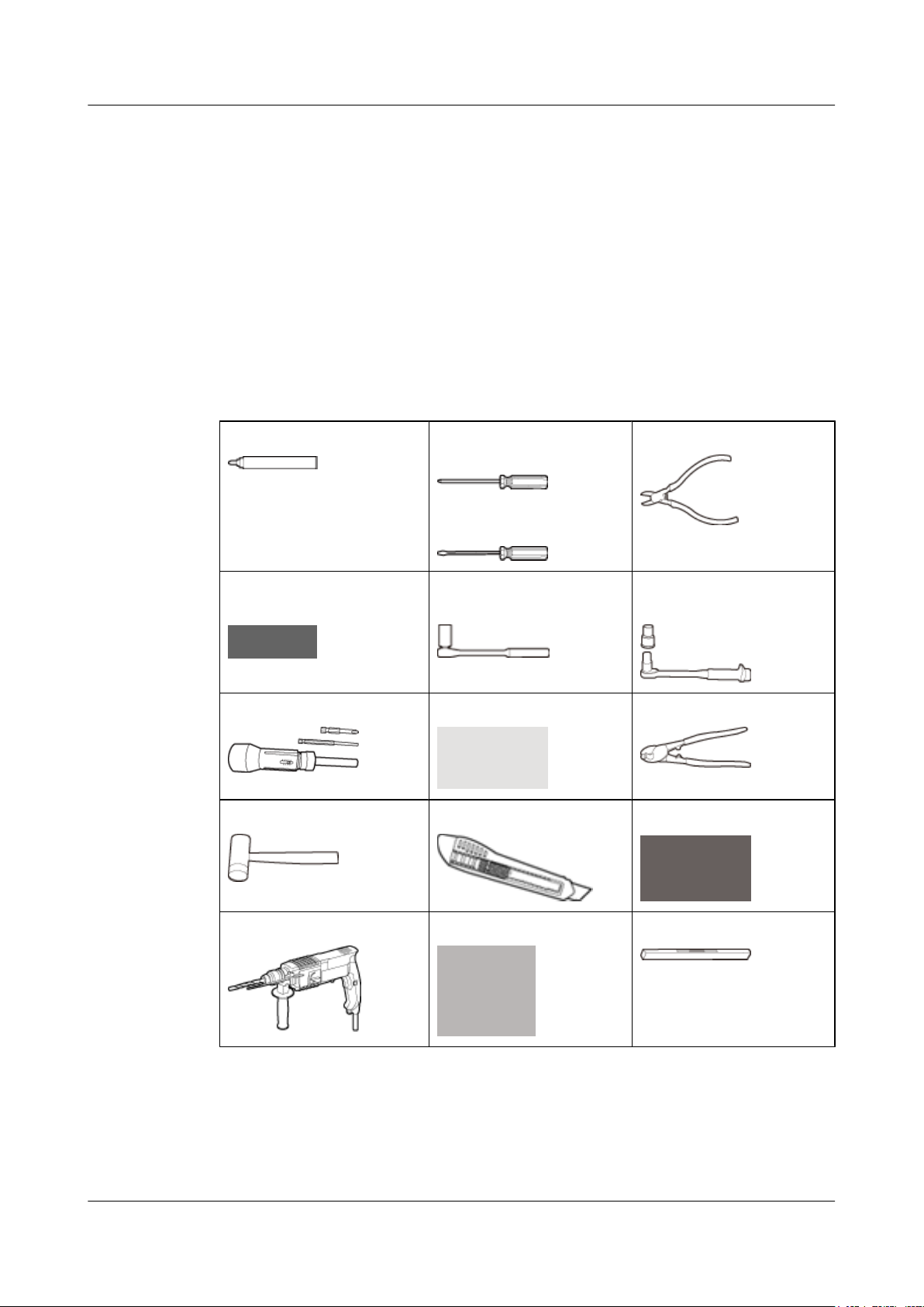
2.2 Tools and Instruments
This section describes the tools and instruments required for installation.
DBS3900(ICR)
Installation Guide
Marker
Adjustable wrench (capacity
≤ 19 mm)
Phillips torque screwdriver Crimping tool Wire clippers
Rubber mallet Guarded blade utility knife Wire stripper
Phillips screwdriver (M4,
M5, M6, and M8)
Flat-head screwdriver (M4,
M5, M6, and M8)
Socket wrench (M10 and
M12)
Diagonal pliers
Torque wrench (30 N·m to 50
N·m)
Hammer drill (Ø16) Heat gun Level
2-2 Huawei Proprietary and Confidential
Copyright © Huawei Technologies Co., Ltd.
Issue 01 (2011-03-30)
DBS3900(ICR)
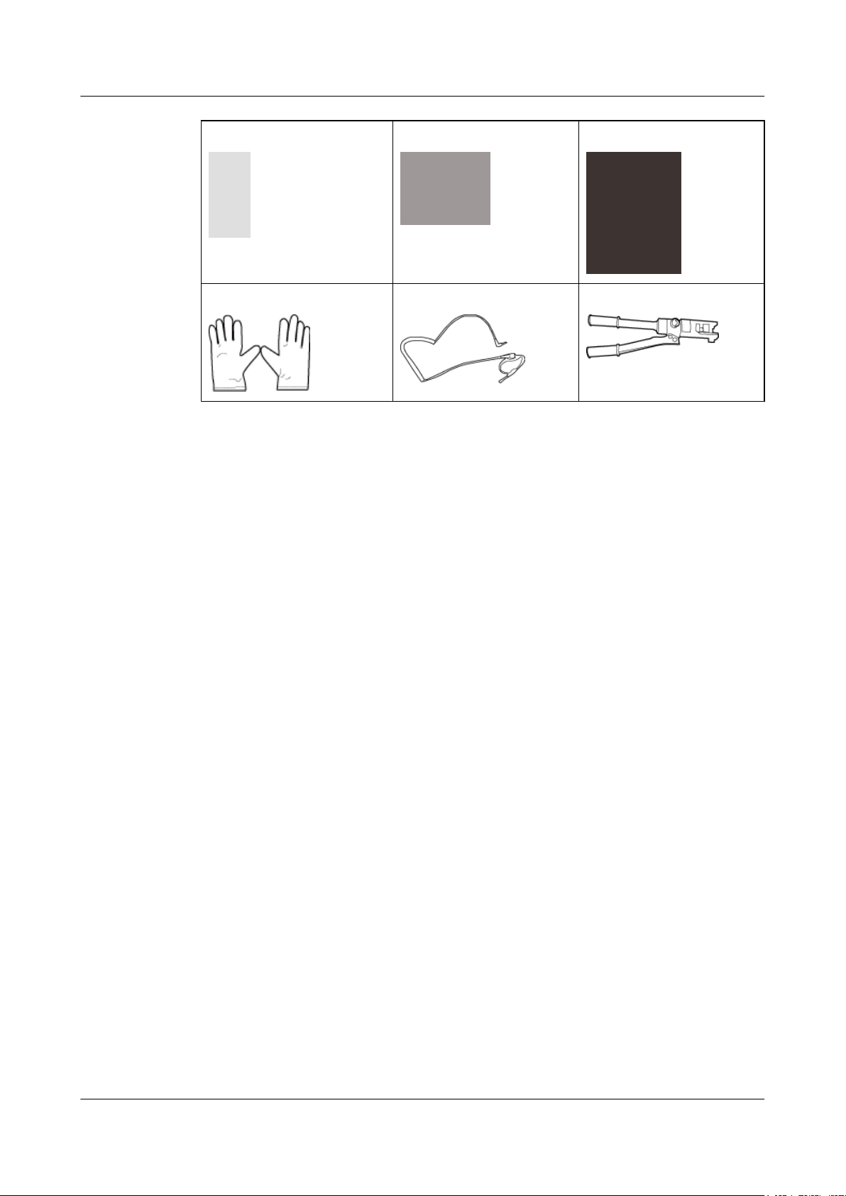
Installation Guide 2 Installation Preparations
Multimeter Measuring tape Vacuum cleaner
ESD gloves ESD wrist strap Hydraulic pliers
2.3 Skills and Requirements for Onsite Personnel
Onsite personnel must be qualified and trained. Before performing any operation, onsite
personnel must be familiar with correct operation methods and safety precautions.
Before the installation, pay attention to the following items:
l The customer's technical engineers must be trained by Huawei and be familiar with the
proper installation and operation methods.
l The number of onsite personnel depends on the engineering schedule and installation
environment. Generally, only three to five onsite personnel are necessary.
Issue 01 (2011-03-30) Huawei Proprietary and Confidential
Copyright © Huawei Technologies Co., Ltd.
2-3


DBS3900(ICR)
Installation Guide 3 Information About the Installation
3 Information About the Installation
About This Chapter
This chapter describes the information about the installation, including exterior, installation
scenario, and space requirements
3.1 Overview of Devices
This chapter describes the devices involved in the installation of the DBS3900.
3.2 Installation Options
The installation options vary according to height-restricted and height-unrestricted scenarios.
3.3 Dimensions and Installation Clearance Requirements
This section describes the dimensions and installation clearance requirements for the relevant
devices.
Issue 01 (2011-03-30) Huawei Proprietary and Confidential
Copyright © Huawei Technologies Co., Ltd.
3-1

3 Information About the Installation
3.1 Overview of Devices
This chapter describes the devices involved in the installation of the DBS3900.
IFS06
The
IFS06 is an Indoor Floor Installation Support (IFS). It is used for installing DBS3900 devices
in a centralized manner.
DBS3900(ICR)
Installation Guide
(1) Cable rack (2) Ground bar 2 (3) Rear foot (4) Front foot
(5) Adjustable beam (6) Ground bar 1 (7) Main frame -
NOTE
In this document, the cable colors and exteriors of the devices are for reference only.
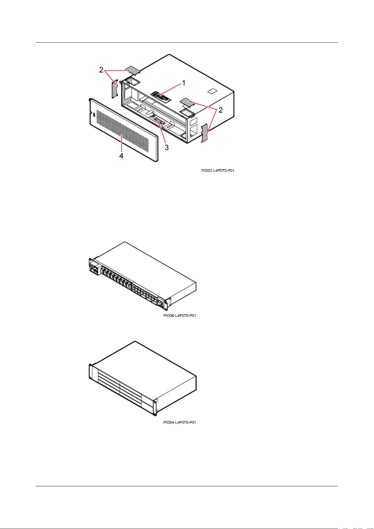
IMB03
IMB03 is an Indoor Mini Box (IMB). It is used for installing the BBU and power devices.
The
3-2 Huawei Proprietary and Confidential
Copyright © Huawei Technologies Co., Ltd.
Issue 01 (2011-03-30)
DBS3900(ICR)
Installation Guide 3 Information About the Installation
(1) NO STEPPING sign (2) Protection plate
(3) Slot assignment label (4) Cover plate
Other Devices
Figure 3-1 DCDU-03B
Figure 3-2 BBU3900
Issue 01 (2011-03-30) Huawei Proprietary and Confidential
Copyright © Huawei Technologies Co., Ltd.
3-3
3 Information About the Installation
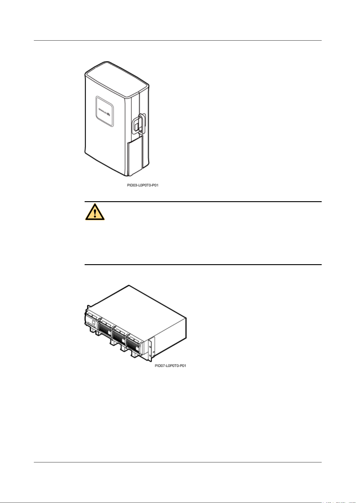
Figure 3-3 RRU
DBS3900(ICR)
Installation Guide
WARNING
l Place the foam pad or cardboard under the RRU to prevent any damage to the housing of the
RRU.
l The load-bearing capacity of the RF ports at the bottom of the RRU is low. Do not stand the
RRU upright.
Figure 3-4 Power equipment (AC/DC)
3-4 Huawei Proprietary and Confidential
Copyright © Huawei Technologies Co., Ltd.
Issue 01 (2011-03-30)
 Loading...