


RRU3201 V100R001C01
Installation Guide
Issue: 01
Part Number:
Date: 2009-08-10
HUAWEI TECHNOLOGIES Co., Ltd.

Contents
Safety Information …………………………………………….….……
Installation Tools ………………………………………….…………..
Space Requirements …………………………………….……..…….
Installation Modes …………………………………………………….
Installation Procedure …………………………………….………….
Components Delivered with the RRU ……………………………..
Installing the RRU on a Metal Pole ………………..……………….
Installing the RRU on a Wall ………………………………………..
Installing the RRU on a U-Steel ……………….……….…………..
Installing the RRU on an Angle Steel ……………………………..
Installing the RRU Cables …………………………………………..
2
3
4
5
6
6
7
12
15
15
16
RRU Hardware Installation Checklist ……………………………..
Powering On the RRU …………………………………...…………..
Reference ………………………………………………………..……..
Change History …………………………………...…………………..
23
23
24
30
1
Copyright © Huawei Technologies Co., Ltd. 2009. All rights reserved.
Safety Information
Following All Safety Precautions
Before any operation, read the instructions and precautions in this document carefully to minimize the possibility
of accidents.
The Danger, Caution, and Note items in the documents do not cover all the safety precautions that must be
followed. They only provide the generic safety precautions for operations.
When operating Huawei products and equipment, you must comply with safety precautions and special safety
instructions related to corresponding equipment provided by Huawei. The safety precautions in the document
are related to only Huawei products. Huawei is not liable for any consequence that results from the violation of
universal regulations for safety operations and safety codes on design, production, and equipment use.
Complying with the Local Safety Regulations
When operating the device, comply with the local safety regulations. The safety precautions provided in the
documents are supplementary. You must comply with the local safety regulations.
Qualified Personnel Only
The personnel in charge of installation and maintenance must be trained and master the correct operating
methods and safety precautions before beginning work.
Symbols
DANGER
WARNING
CAUTION
TIP
NOTE
Indicates a hazard with a high level of risk, which if not avoided,will result in death or
serious injury.
Indicates a hazard with a medium or low level of risk, which if not avoided, could result
in minor or moderate injury.
Indicates a potentially hazardous situation, which if not avoided,could result in
equipment damage, data loss, performance degradation, or unexpected results.
Indicates a tip that may help you solve a problem or save time.
Provides additional information to emphasize or supplement important points of the
main text.
Safety of Personnel
• The high voltage power supply provides power for running the system. Direct contact with the high voltage
power supply or contact through damp objects may result in fatal danger.
• Non-standard and improper high voltage operations may result in fire and electric shock.
• In a thunderstorm, do not perform operations on high voltage and AC power supply facilities or on a steel
tower and mast.
• Ground the device before powering on the device. Otherwise, the personnel and device are in danger.
• Power off the device before performing operations on the power supply equipment.
• High power radio-frequency signals are harmful to human body. Before installing or maintaining an antenna
on a steel tower or mast with a large number of transmitter antennas, the operator should coordinate with all
parties to ensure that the transmitter antennas are shut down.
• When handling optical fibers, do not stand close to, or look into the optical fiber outlet with unaided eyes.
• Protect yourself when drilling holes. Flying dust may hurt your eyes or you may inhale the dust.
• Power off the batteries before connecting the cables to the batteries. Otherwise, casualties may occur.
• When working at a height, be cautious about falling objects.
Device Safety
• Check the electrical connection of the device before operation and ensure that the device is reliably grounded.
• The static electricity generated by the human body may damage the electrostatic sensitive components on
the circuit board, such as the large-scale integrated circuit (LIC). Wear an ESD wrist strap or ESD gloves when
performing the operation.
• When working on batteries, take measures to prevent short circuits in the batteries and electrolyte spill/loss.
The electrolyte may erode metal and boards, or even cause rust of the equipment or short circuits in the boards.
• When the equipment is unpacked, it must be powered on in 24 hours. The maximum duration of the poweroff state of the equipment is 24 hours during maintenance.
2
Copyright © Huawei Technologies Co., Ltd. 2009. All rights reserved.

Installation Tools
Hammer drill
Heat gun
Claw hammer
ESD gloves
Knife
Vacuum cleaner
Flat-head screwdriver (M3 to M6)Phillips screwdriver (M3~M6)
Wire Stripper
Power cable crimping tool Cable cutter
Level
Multimeter
Torque screwdriver
Marker
Adjustable wrench
(with the diameter of at least 32 mm)
Combination wrench
(21mm~21mm) for pole installation
(17mm~17mm) for pole installation
Measuring tape
3
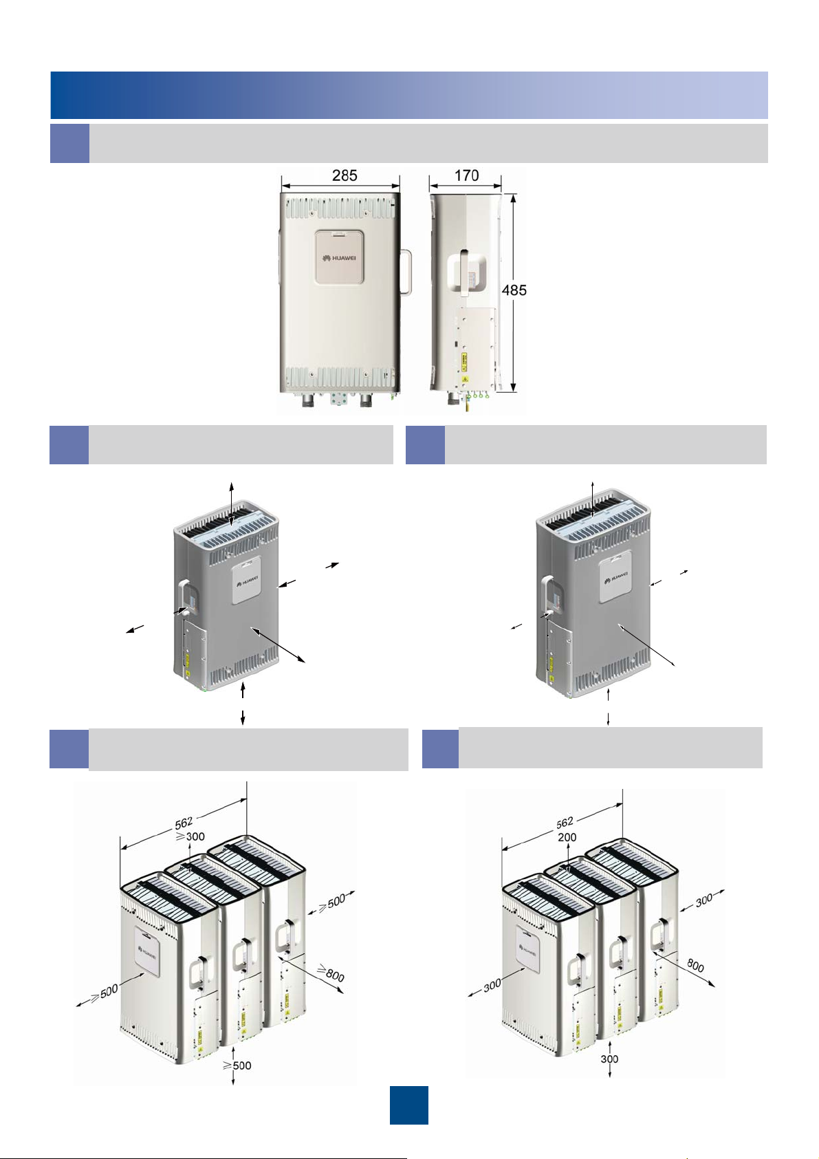
Space Requirements (Unit: mm)
RRU Dimensions
a
Recommended Clearance for a
b
Single RRU
≥300
≥
0
0
≥3
≥500
≥
8
0
Recommended Clearance for
d
Multiple Centralized RRUs
Minimum Clearance for a Single
c
RRU
200
0
0
6
0
0
1
0
300
0
0
4
6
0
0
Minimum Clearance for Multiple
e
Centralized RRUs
4
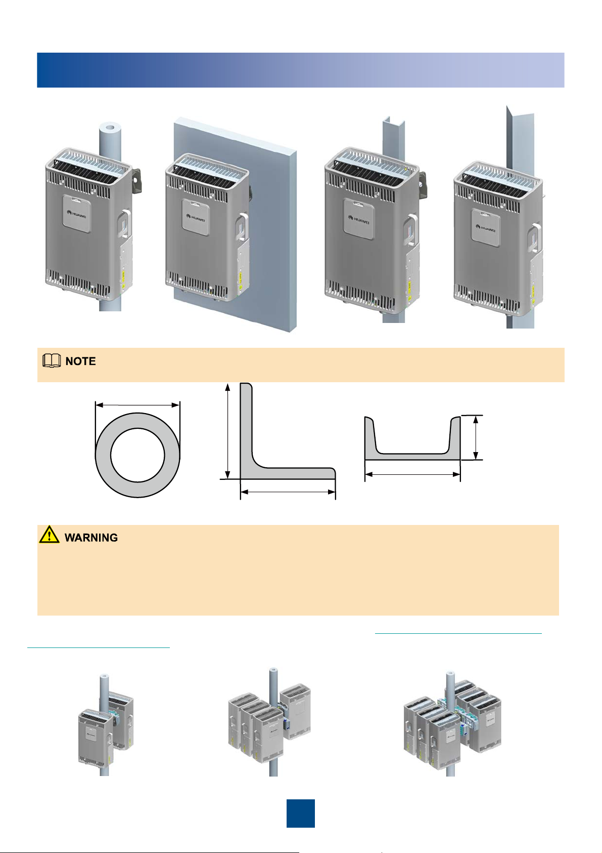
Installation Modes
On a metal pole On a wall On an angle steelOn a U-steel
The following figure shows the specifications of the metal pole, angle steel, and U-steel where the RRU is installed.
60mm~114mm
80mm
80mm
~
~
63mm
63mm
50mm
50mm
~
~
30mm
30mm
50mm~100mm
63mm~80mm
Metal pole
Angle steel U-steel
z A maximum of two RRUs can be installed on a metal pole with a diameter of 60 mm to 76 mm, and the installation mode
must be standard mode. Three or more RRUs must be installed on a metal pole with a diameter of 76 mm to 114 mm in a
centralized way.
z It is recommended that only one RRU be installed on a U-steel or angle steel.
z When installed on a tower, one RRU can be installed only in standard mode or revers e mode rather than side-mounted.
Two RRUs cannot be installed in back-to-back mode.
The RRU can be installed on the tower. For details, see page 24 Lifting the RRU and Installation
Components to the Tower.
The following figures show the installations of multiple RRUs on the metal poles.
2RRU 4RRU 6RRU
5
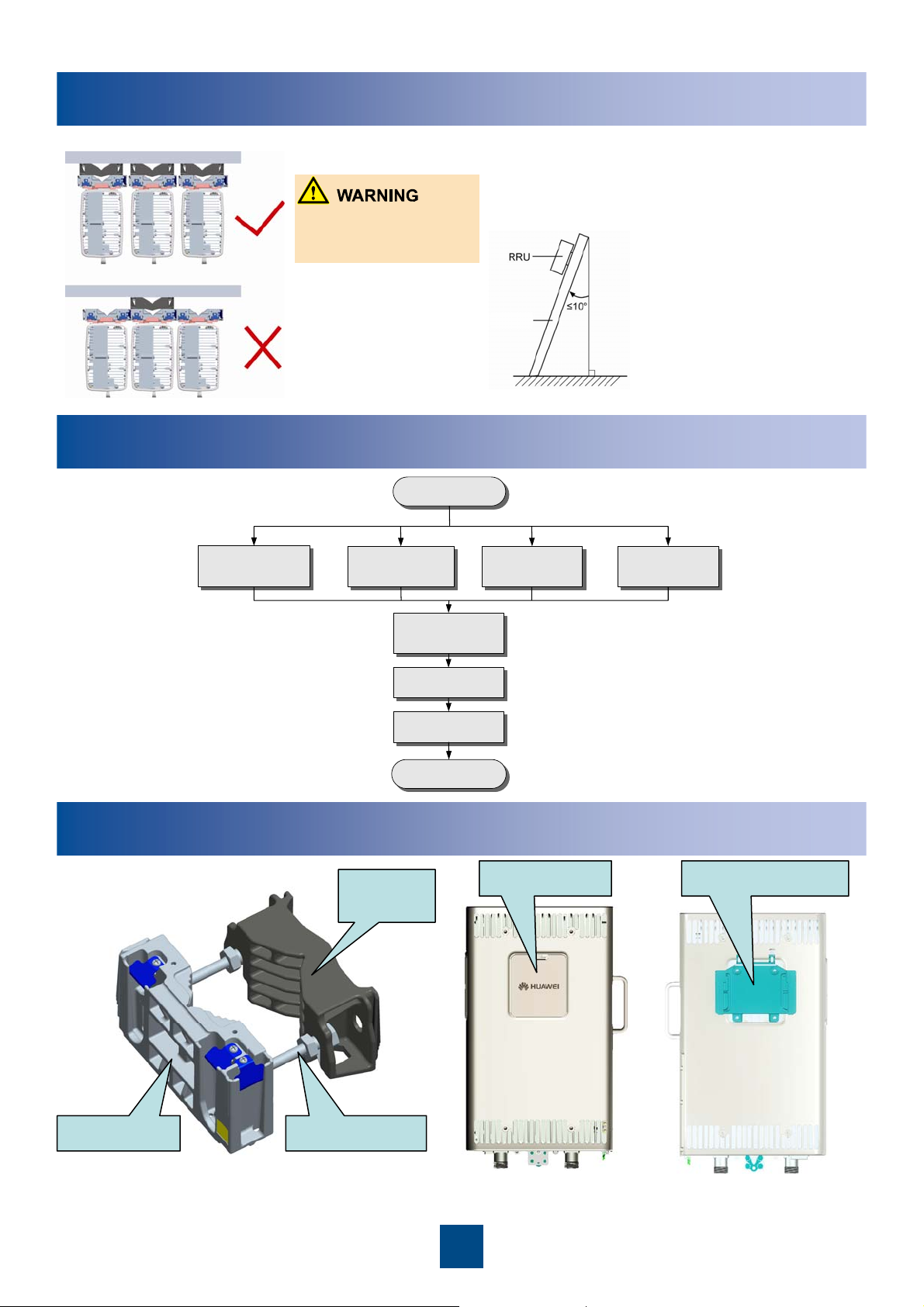
Installation Modes
The brackets cannot be
combined when the RRUs
are installed on the wall.
Installation Procedure
When the RRU is installed
on a U-steel or angle steel,
the angle between the Usteel or angle steel and the
longitudinal direction
cannot exceed 10 degrees.
installation carrier
Start
Install the RRU on a
metal pole
(page 7~11)
Install the RRU on a
wall
(page 12~14)
Install the RRU cables
(page16~22)
Check the installation
(page 23)
Power on the RRU
(page 23)
End
Install the RRU on a
U-steel
(page15)
Components Delivered with the RRU
Auxiliary
fixture
Cover plate Attachment plate
Install the RRU on a
angle steel
(page15)
M10x110 BoltMain fixture
Fixture assembly for installing
the RRU
Front of the RRU
6
Back of the RRU
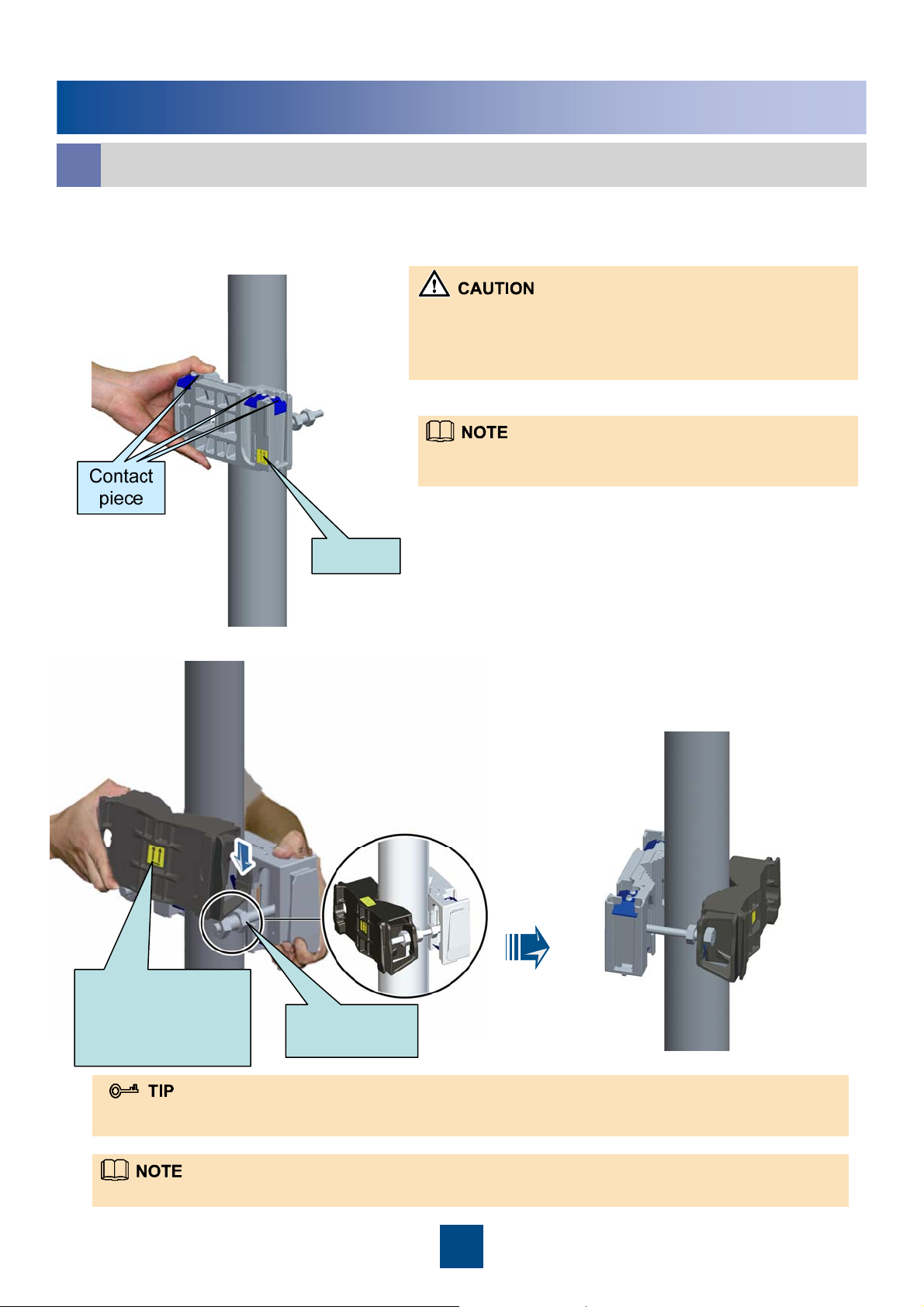
Installing the RRU on a Metal Pole
Installing a Single RRU in Ordinary Mode
a
1. Install the main fixture.
1. Before installing the main fixture, ensure that the contact piece
on the fixture is fixed.
2. When installing the main fixture, keep the arrow on the main
fixture upward.
It is recommended that the bottom of the main fixture be 1200
mm to 1600 mm above the ground for easy maintenance.
Arrow
2. Install the auxiliary fixture between the nuts of the dual-nut bolt assembly on the main fixture.
Ensure that the
arrow on the
auxiliary fixture is
upward.
Dual-nut bolt
assembly
You can fit the auxiliary fixture on one of the dual-nut bolt assemblies before the installation. Thus, you can simply
install the auxiliary fixture by fitting the other end of it on the other dual-nut bolt assembly.
Fit the auxiliary fixture into the dual-nut bolt assemblies.
7
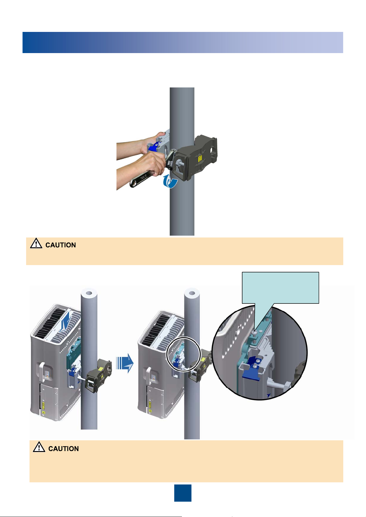
Installing the RRU on a Metal Pole
3. Use an adjustable wrench (with the diameter of at least 21 mm) to tighten the dual-nut bolt
assemblies. In this way, the main and auxiliary fixtures are securely mounted on the pole.
When tightening the nuts, ensure that the two dual-nut bolt assemblies are tightened simultaneously. The fastening torque is
40 N• m.
4. Install the RRU on the main fixture.
The screw is a non-
fixed one and is for
removing the RRU.
1. When you perform this operation, you need to place the foam pads or paper under the RRU to avoid any damage to
the shell.
2. The RF port at the bottom of the RRU does not have load bearing capacity. Do not place the RRU on the ground on
its bottom during the installation.
8
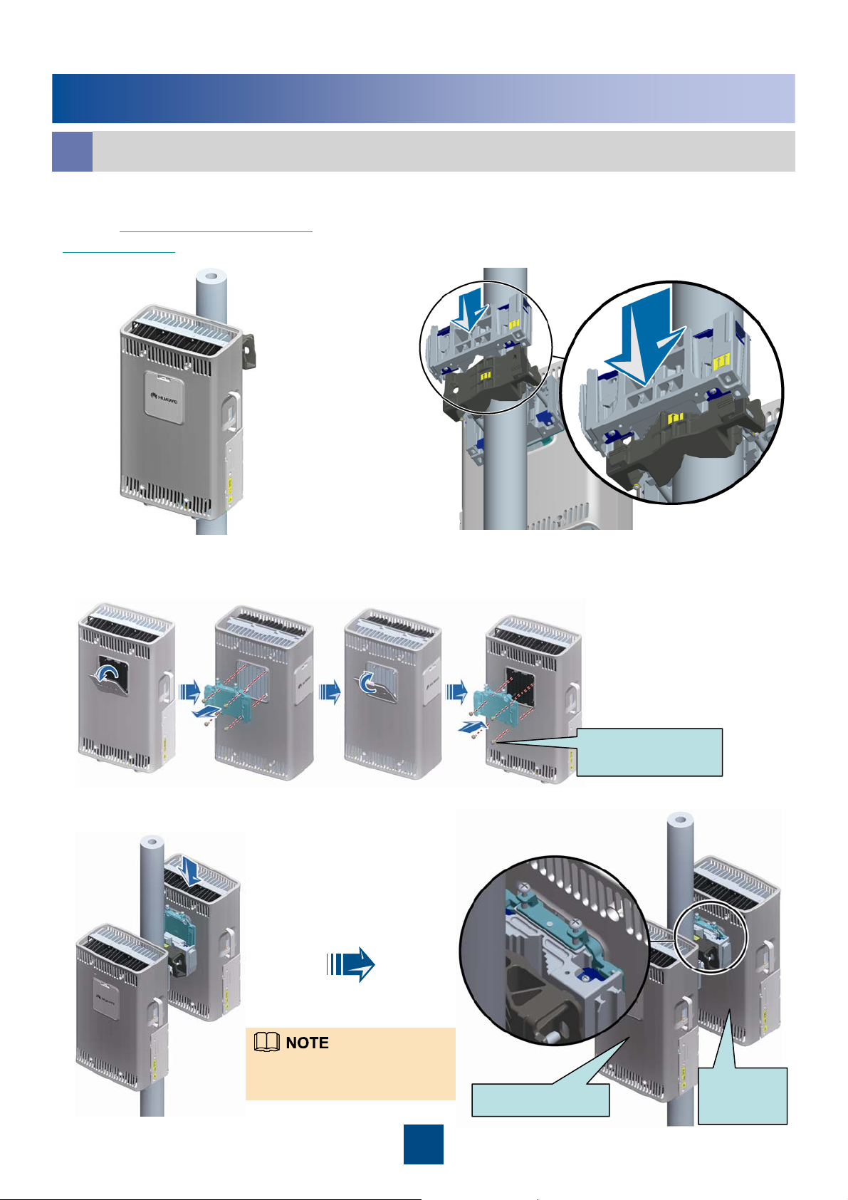
Installing the RRU on a Metal Pole
b
1. Install an RRU first. For details, see
page 7 Installing a Single RRU in
Ordinary Mode.
3. Reinstall the cover plate and attachment plate on the second RRU to interchange their
positions.
Installing Two RRUs in Back-To-Back Mode
2. Install the main fixture of another RRU.
Ensure that the main and auxiliary fixtures
are perfectly fitted.
4. Install the second RRU on the main fixture in reverse mode.
Ensure that the cabling cavities of
the two RRUs face the same
direction when installing the RRUs
Ordinary mode
9
M6x16
torque
: 4.7 N
.
M
Reverse
mode
 Loading...