

eRelay3.0 RRN3301
Product Description
Issue
V1.0
Date
2012-10-20
HUAWEI TECHNOLOGIES CO., LTD.

Huawei Proprietary and Confidential
Copyright ©Huawei Technologies Co.,Ltd.
i
»ªÎª×¨Óкͱ£ÃÜÐÅÏ¢
i
Copyright © Huawei Technologies Co., Ltd. 2012. All rights reserved.
No part of this document may be reproduced or transmitted in any form or by any means without prior written
consent of Huawei Technologies Co., Ltd.
Trademarks and Permissions
and other Huawei trademarks are trademarks of Huawei Technologies Co., Ltd.
All other trademarks and trade names mentioned in this document are the property of their respective holders.
Notice
The purchased products, services and features are stipulated by the contract made between Huawei and the customer.
All or part of the products, services and features described in this document may not be within the purchase scope or
the usage scope. Unless otherwise specified in the contract, all statements, information, and recommendations in this
document are provided "AS IS" without warranties, guarantees or representations of any kind, either express or
implied.
The information in this document is subject to change without notice. Every effort has been made in the preparation
of this document to ensure accuracy of the contents, but all statements, information, and recommendations in this
document do not constitute a warranty of any kind, express or implied.
Huawei Technologies Co., Ltd.
Address:
Huawei Industrial Base
Bantian, Longgang
Shenzhen 518129
People's Republic of China
Website:
http://www.huawei.com
Email:
support@huawei.com

eRelay 3.0 RRN3301 Product Description
Huawei Proprietary and Confidential
Copyright ©Huawei Technologies Co.,Ltd.
ii
»ªÎª×¨Óкͱ£ÃÜÐÅÏ¢
ii
Contents
1 Product Positioning ............................................................................................................... 1
1.1 Positioning ........................................................................................................................................... 1
1.2 Benefits ................................................................................................................................................ 2
2 Product Architecture ............................................................................................................ 4
2.1 Overview .............................................................................................................................................. 4
2.2 Exterior ................................................................................................................................................ 4
2.3 Ports ..................................................................................................................................................... 5
3 Application Scenarios ........................................................................................................... 6
4 OM .......................................................................................................................................... 8
4.1 Overview .............................................................................................................................................. 8
4.2 OM Structure........................................................................................................................................ 8
5 Specifications ....................................................................................................................... 10
5.1 Capacity Specifications ...................................................................................................................... 10
5.2 Device-Related Specifications ........................................................................................................... 10
5.3 Reliability Specifications ................................................................................................................... 11
eRelay 3.0 RRN3301 Product Description
Huawei Proprietary and Confidential
Copyright ©Huawei Technologies Co.,Ltd.
1
»ªÎª×¨Óкͱ£ÃÜÐÅÏ¢
1
eRelay is a wireless transport networking solution, used on the higher band of TDD
spectrum (<6GHz). As a network element (NE) in the eRelay system, eRelay remote
node(RRN) works together with eRelay BS to perform wireless backhaul.
1.1 Positioning
With the expansion of mobile broadband users (MBB), network capacity is insufficient
in some outdoor hot spot areas, affecting user experience. Operators use compact
devices such as AP, Micro, and Pico eNodeBs to cover hot spots. In the preceding
scenarios, if access devices for fixed networks, such as optical fibers, are used for
backhaul, deployment costs are high and fixed network resources are difficult to obtain.
Therefore, wireless backhaul is required to solve the problem.
1 Product Positioning
As a wireless backhaul solution, eRelay adopts TDD technologies and provides high
throughput with short delay. Compared with backhaul in fixed networks, deployment
costs for eRelay are low and frequency resources are accessible. Compared with micro
waves, eRelay has advantages in transmission in non line of sight (NLOS) scenarios.
In the eRelay solution, the eRelay RRN provides wireless backhaul channels for
Served Equipments such as Macro, Micro, Pico, video surveillance, AP and fixed
network equipment. RRN access eRelay BS through air interfaces.
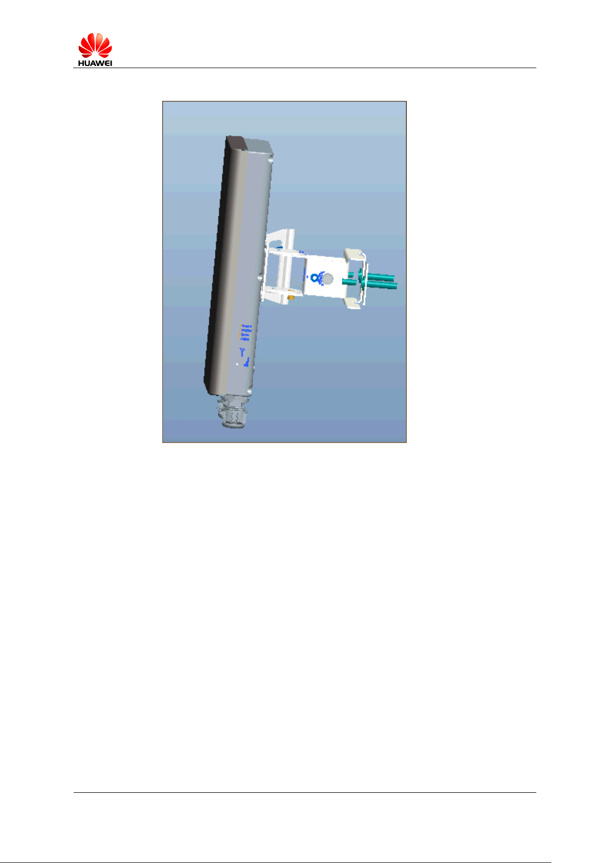
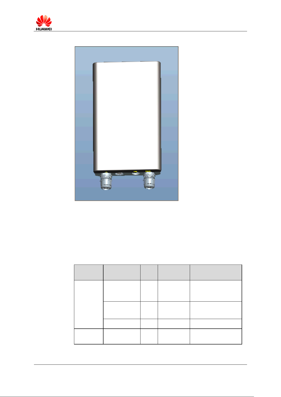
RRN3301 is one of the Huawei eRelay module.
Figure 1-1 shows an eRelay RRN3301.
eRelay 3.0 RRN3301 Product Description
Huawei Proprietary and Confidential
Copyright ©Huawei Technologies Co.,Ltd.
2
Figure 1-1 eRelay RRN3301
1.2 Benefits
Larger Capacity and Throughput with Flexible Transmit Power
A single eRelay RRN3301 can be connected to a maximum of two Served
Equipments.
A single eRelay RRN3301 supports the maximum uplink and downlink rate of 28
Mbit/s and 80Mbit/s, respectively.
Optimized Transmission Mode with Low Costs
eRelay RRN3301 support layer 2 switching.
Flexible Installation for Fast Network Deployment with Low CAPEX
The eRelay RRN3301 has a highly integrated structure with a small size and light
weight, facilitating installation and maintenance and reducing the capital
expenditure (CAPEX).
eRelay RRN3301 can be mounted onto a pole, and equipment rooms are not
required. eRelay RRN3301 can be flexibly installed on different places and

eRelay 3.0 RRN3301 Product Description
Huawei Proprietary and Confidential
Copyright ©Huawei Technologies Co.,Ltd.
3
require small space. Therefore, sites are easily obtained, network deployment
flexibility is enhanced, and site lease costs are reduced.
eRelay 3.0 RRN3301 Product Description
Huawei Proprietary and Confidential
Copyright ©Huawei Technologies Co.,Ltd.
4
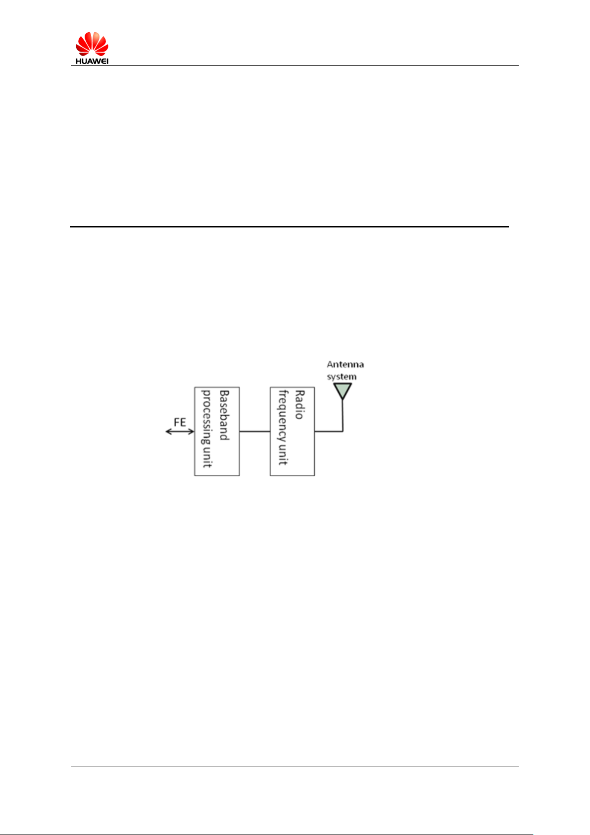
2.1 Overview
An eRelay RRN3301 consists of a modem, and panel antenna. Figure 2-1 shows the
eRelay RRN3301 architecture.
Figure 2-1 eRelay RRN3301 architecture
2 Product Architecture
Modules in eRelay RRN3301 have following functions:
2.2 Exterior
Figure 2-2 shows the eRelay RRN3301 exterior.
The modem enables the connection between the RRN and eRelay BS over air
interfaces.
The panel antenna provides directional transmission and receipt of LTE signals
with high gains. The specifications are as follows:
Gain: 17±1 dBi for 3.5G.
Horizontal 3dB beamwidth: 40°
Vertical3 dB beamwidth: 20°
eRelay 3.0 RRN3301 Product Description
Huawei Proprietary and Confidential
Copyright ©Huawei Technologies Co.,Ltd.
5
Figure 2-2 eRelay RRN3301 exterior
Module
Port
Num
ber
Connector
Description
Bottom
panel
PoE/FE0
1
RJ45
Power over Ethernet
(PoE) or service
Ethernet port 1
DBG
1
USB
Combined virtual
commissioning serial
and Ethernet port
FE1
1
RJ45
Service Ethernet port 2
Indicator
panel
/ / /
PWR, FE1, FE2, RUN,
and SIG indicators
2.3 Ports
The eRelay RRN3301 provides ports on its bottom panel and indicator panel, as
described in Table 2-1.
Table 2-1 Ports on the eRelay RRN3301
eRelay 3.0 RRN3301 Product Description
Huawei Proprietary and Confidential
Copyright ©Huawei Technologies Co.,Ltd.
6
3 Application Scenarios
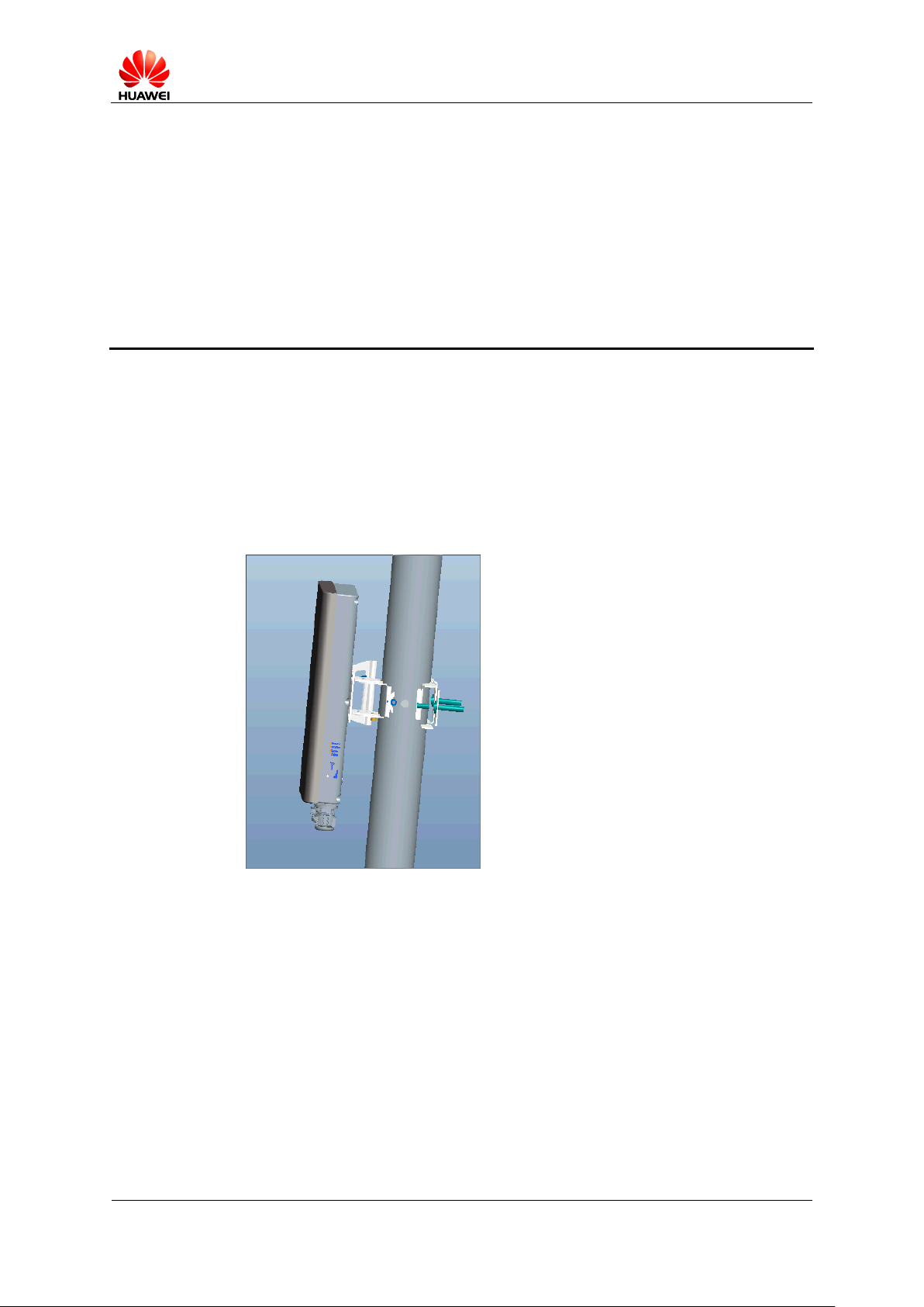
Working together with auxiliary devices, eRelay RRN3301 can be installed indoors
and outdoors based on operator requirements.
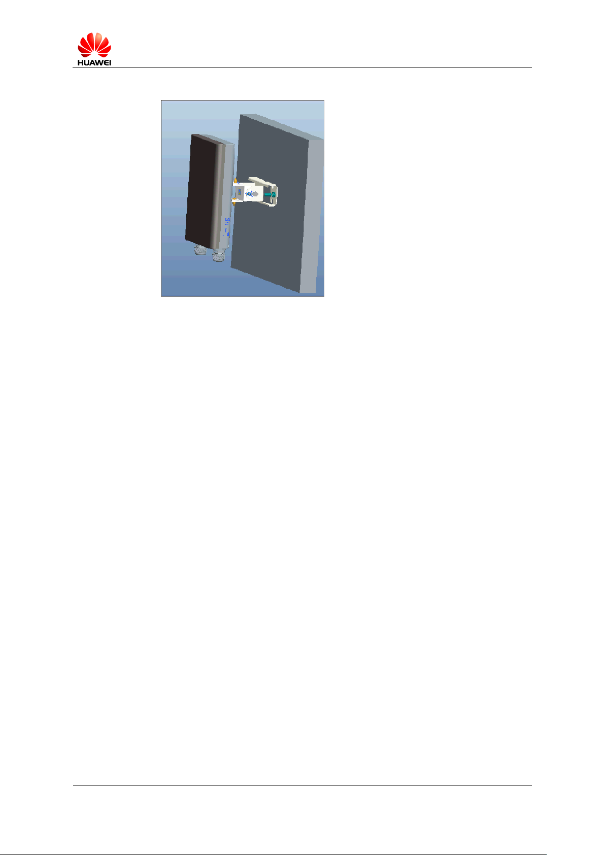
An eRelay RRN3301 can be mounted onto a pole or on the wall, as shown in Figure
3-1 and Figure 3-2.
Figure 3-1 eRelay RRN3301 mounted onto the pole
eRelay 3.0 RRN3301 Product Description
Huawei Proprietary and Confidential
Copyright ©Huawei Technologies Co.,Ltd.
7
Figure 3-2 eRelay RRN3301 installed on the wall
eRelay 3.0 RRN3301 Product Description
Huawei Proprietary and Confidential
Copyright ©Huawei Technologies Co.,Ltd.
8
4.1 Overview
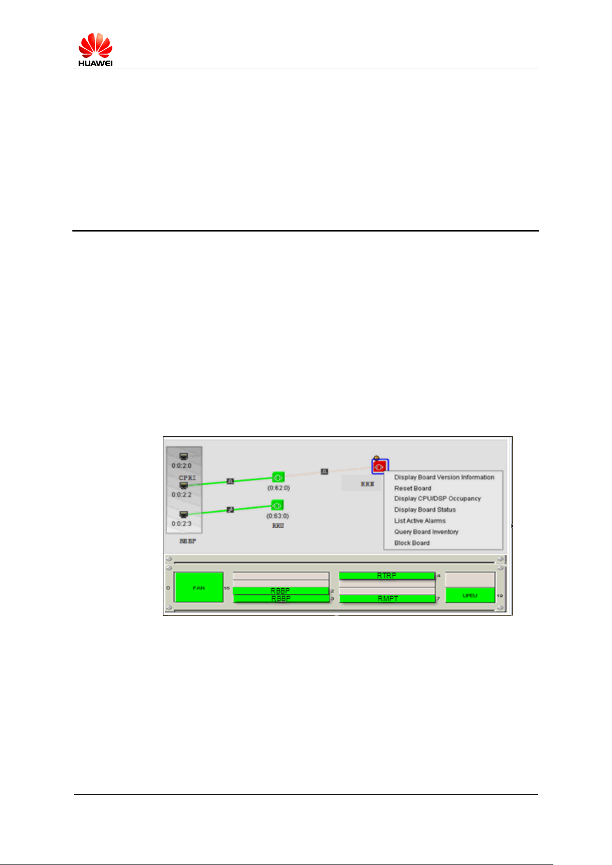
The eRelay RRN3301 will be managed as a board of BS by operation and maintenance
system.
4.2 OM Structure
4 OM
Figure 4-1 shows the operation and maintenance system of the eRelay RRN3301.
Figure 4-1 OM system of the eRelay RRN3301
The OM system consists of the LMT and the M2000.
The LMT is used to maintain a single eRelay RRN3301.
To maintain the eRelay RRN3301 remotely, connect the LMT to the eRelay
RRN3301 through the Internet Protocol (IP) network.
The M2000, a mobile element management system provided by Huawei, is used to
remotely maintain multiple eRelay RRN3301s of different types or software versions.
The OM system provides the following functions:
The LMT performs functions such as data configuration, alarm monitoring,
commissioning, and software upgrade.

eRelay 3.0 RRN3301 Product Description
Huawei Proprietary and Confidential
Copyright ©Huawei Technologies Co.,Ltd.
9
The M2000 performs functions such as data configuration, alarm monitoring,
performance monitoring, and software upgrade.
Both the LMT and the M2000 support MML and GUI modes.
eRelay 3.0 RRN3301 Product Description
Huawei Proprietary and Confidential
Copyright ©Huawei Technologies Co.,Ltd.
10
eRelay RRN3301 specifications include capacity specifications, device-related
Item
Specifications
Maximum throughput
of a single eRelay
RRN
Downlink throughput: 80 Mbit/s
Uplink throughput: 28 Mbit/s
Maximum number of
Served Equipments
connected to a single
eRelay RRN
2
Item
Specifications
eRelay RRN3301
Mode
TDD
Frequency
band
RX band
(MHz)
TX band
(MHz)
Bandwidth
(MHz)
3.5GHz
(Band 43)
3650MHz
-3675MH
z
3650MHz
-3675MH
z
10M/20M
specifications, and reliability specifications.
5.1 Capacity Specifications
Table 5-1 describes the capacity specifications for an eRelay RRN3301.
5 Specifications
Table 5-1 Capacity specifications for an eRelay RRN3301
5.2 Device-Related Specifications
Table 5-2 describes the device specifications for an eRelay RRN3301.
Table 5-2 Device specifications for an eRelay RRN3301
eRelay 3.0 RRN3301 Product Description
Huawei Proprietary and Confidential
Copyright ©Huawei Technologies Co.,Ltd.
11
Item
Specifications
Dimensions (H x W x D)
200 mm × 340 mm × 60 mm
Weight
≤3.5 kg
Power supply
PoE input: -48 V DC, 0.6 A
Item
Specifications
Transmission
ports
Two fast Ethernet (FE) electrical ports, one of which supports
PoE power input.
Maintenance
port
One DBG port
Item
Specifications
Operating
temperature
–40°C to +50°C
Relative
humidity
5% RH to 95% RH
Protection class
IP65
Item
Specifications
System availability
≥ 99.999%
System restarting time(soft-reset)
60s
Table 5-3 describes mechanical and electrical specifications for an eRelay RRN3301.
Table 5-3 Mechanical and electrical specifications for an eRelay RRN3301
Table 5-4 describes the specifications for ports on the eRelay RRN3301.
Table 5-4 Specifications for ports on the eRelay RRN3301
Table 5-5 describes the environment and clock specifications for an eRelay RRN3301.
Table 5-5 Environment and clock specifications for an eRelay RRN3301
5.3 Reliability Specifications
Reliability specifications include system availability, mean time between failures
(MTBF), mean time to repair (MTTR), and system restarting time. Table 5-6 describes
the reliability for an eRelay RRN3301.
Table 5-6 Reliability specifications for an eRelay RRN3301

eRelay 3.0 RRN3301 Product Description
Huawei Proprietary and Confidential
Copyright ©Huawei Technologies Co.,Ltd.
12

eRelay 3.0 RRN3301 Product Description
Huawei Proprietary and Confidential
Copyright ©Huawei Technologies Co.,Ltd.
13
A Acronyms and Abbreviations
C CAPEX
capital expenditure
D DHCP
Dynamic Host Configuration Protocol
F
FE
fast Ethernet
I
IP
Internet Protocol
L
L
Long Term Evolution
M
MBB
mobile broadband
MTBF
mean time between failures
MTTR
mean time to repair
N
NE
network element
O
O&M
operation and maintenance

eRelay 3.0 RRN3301 Product Description
Huawei Proprietary and Confidential
Copyright ©Huawei Technologies Co.,Ltd.
14
P
PoE
power over Ethernet
R RRN
eRelay Remote Node
T TDD
time division duplex

Regulatory Compliance Statement
RRN3301
0168
Issue
Date
02
2014-5-8
HUAWEI TECHNOLOGIES CO., L TD.


Copyright © Huawei Technologies Co., Ltd. 2010. All rights reserved.
No part of this document may be reproduced or transmitted in any form or by any means without prior written
consent of Huawei Technologies Co., Ltd.
Trademarks and Permissions
and other Huawei trademarks are trademarks of Huawei Technologies Co., Ltd.
All other trademarks and trade names mentioned in this document are the property of their respective holders.
Notice
The purchased products, services and features are stipulated by the contract made between Huawei and the customer.
All or part of the products, services and features described in this document may not be within the purchase scope or
the usage scope. Unless otherwise specified in the contract, all statements, information, and recommendations in this
document are provided "AS IS" without warranties, guarantees or representations of any kind, either express or
implied.
The information in this document is subject to change without notice. Every effort has been made in the preparation
of this document to ensure accuracy of the contents, but all statements, information, and recommendations in this
document do not constitute the warranty of any kind, express or implied.
Huawei Technologies Co., Ltd.
Address: Huawei Industrial Base
Bantian, Longgang
Shenzhen 518129
People's Republic of China
Website: http://www.huawei.com
Email: support@huawei.com
Issue (02)
Huawei Proprietary and Confidential
Copyright © Huawei Technologies Co., Ltd.
i


1 Regulatory Compliance Statement
1 Regulatory Compliance Statement
About This Chapter
1.1 Declaration of Conformity to European Directives
Declaration of Conformity
to European Directives
Issue (02) Huawei Proprietary and Confidential
Copyright © Huawei Technologies Co., Ltd.
1-1

1 Regulatory Compliance Statement
Figure 1-1 Declaration of Conformity to European Directives
1-2 Huawei Proprietary and Confidential
Copyright © Huawei Technologies Co., Ltd.
Issue (02)

2 Regulatory Compliance Information
2 Regulatory Compliance Information
About This Chapter
2.1 Regulatory Compliance Standards
2.2 European Regulatory Compliance
2.3 U.S.A Regulatory Compliance
2.4 Japanese Regulatory Compliance
2.5 CISPR 22 Compliance
2.1 Regulatory Compliance Standards
The Product complies with the standards listed in Table 2-1.
Table 2-1 Regulatory compliance standards
Discipline Standards
EMC
z
CISPR22 Class B
z
CISPR24
z
EN55022 Class B
z
EN50024
z
ETSI EN 301 489 Class B
z
CFR 47 FCC Part 15 Class B
z
FCC Part 90z
z
RSS-192
z
RSS-197
z
RSS-102
z
ICES 003 Class B
z
AS/NZS CISPR22 Class B
z
GB9254 Class B
z
VCCI Class B
z
CNS 13438 Class B
z
IEC/EN 61000-6-1
z
IEC/EN 61000-6-3
Issue (02) Huawei Proprietary and Confidential
Copyright © Huawei Technologies Co., Ltd.
2-3

2 Regulatory Compliance Information
Discipline Standards
Safety
RF
Health
z
IEC 60950-1
z
IEC/EN60215
z
IEC/EN41003
z
EN 60950-1
z
UL 60950-1
z
UL 60950-22
z
CSA C22.2 No 60950-1
z
AS/NZS 60950.1
z
BS EN 60950-1
z
IS 13252
z
GB4943
z
GB8898
z
ETSI EN 301 908-1
z
ETSI EN 301 908-13
z
ICNIRP Guideline
z
1999-519-EC
z
EN 50385
z
OET Bulletin 65
z
IEEE Std C95.1
z
EN 60215
Environmental protection
Grounding
z
2002/95/EC & 2011/65/EU (RoHS)
z
EC NO. 1907/2006 (REACH)
z
2002/96/EC&2012/19/EU(WEEE)
z
ITU-T K.27
z
ETSI EN 300 253
2-4 Huawei Proprietary and Confidential
Copyright © Huawei Technologies Co., Ltd.
Issue (02)

2 Regulatory Compliance Information
Discipline Standards
Note:
EMC: electromagnetic compatibility
NEBS: Network Equipment Build Standard
RF: radio frequency
CISPR: International Special Committee on Radio Interference
EN: European Standard
ETSI: European Telecommunications Standards Institute
CFR: Code of Federal Regulations
FCC: Federal Communication Commission
IEC: International Electrotechnical Commission
AS/NZS: Australian/New Zealand Standard
VCCI: Voluntary Control Council for Interference
CNS: Chinese National Standard
UL: Underwriters Laboratories
CSA: Canadian Standards Association
BS: British Standard
IS: Indian Standard
GR: general requirement
FDA: Food and Drug Administration
BTS: base transceiver station
GSM: Global System for Mobile communications
WLAN: wireless local area network
ICNIRP: International Commission on Non-Ionizing Radiation Protection
OET: Office of Engineering Technology
IEEE: Institute of Electrical and Electronics Engineers
RoHS: restriction of the use of certain hazardous substances
2.2 European Regulatory Compliance
The Product complies with the following European directives and regulations.
z
2004/108/EC (EMC)
z
2006/95/EC (low voltage)
z
1999/5/EC (R&TTE)
z
2002/95/EC & 2011/65/EU (RoHS)
z
EC NO. 1907/2006 (REACH)
z
2002/96/EC&2012/19/EU (WEEE)
The Product complies with Directive 2002/95/EC, 2011/65/EU and other similar regulations
from the countries outside the European Union, on the RoHS in electrical and electronic
Issue (02) Huawei Proprietary and Confidential
Copyright © Huawei Technologies Co., Ltd.
2-5

2 Regulatory Compliance Information
equipment. The device does not contain lead, mercury, cadmium, and hexavalent chromium
and brominated flame retardants (Polybrominated Biphenyls (PBB) or Polybrominated
Diphenyl Ethers (PBDE)) except for those exempted applications allowed by RoHS directive
for technical reasons.
Product complies with Regulation EC NO. 1907/2006 (REACH) and other similar regulations
from the countries outside the European Union. Huawei will notify to the European Chemical
Agency (ECHA) or the customer when necessary and regulation requires.
Product complies with Directive 2002/96/EC&2012/19/EU on waste electrical and electronic
equipment (WEEE). Huawei is responsible for recycling its end-of-life devices, and please
contact Huawei local service center when recycling is required. Huawei strictly complies with
the EU Waste Electrical and Electronic Equipment Directive (WEEE Directive) and electronic
waste management regulations enacted by different countries worldwide. In addition, Huawei
has established a system for recycling and reuse of electronic wastes, and it can provide
service of dismantling and recycling for WEEE. By Huawei recycling system, the waste can
be handled environmentally and the resource can be recycled and reused fully, which is also
Huawei WEEE stratagem in the word. Most of the materials in product are recyclable, and our
packaging is designed to be recycled and should be handled in accordance with your local
recycling policies.
In accordance with Article 11(2) in Directive 2002/96/EC&2012/19/EU (WEEE), products
were marked with the following symbol: a cross-out wheeled waste bin with a bar beneath as
below:
2.3 U.S.A Regulatory Compliance
2.3.1 FCC Part 15
2.3.1 FCC Part 15
The Product complies with Part 15 of the FCC Rules. Operation is subject to the following
two conditions:
z
This device does not cause harmful interference.
z
This device must accept any interference receive d, inc luding int erfere nce that may cause
undesired operation.
2-6 Huawei Proprietary and Confidential
Copyright © Huawei Technologies Co., Ltd.
Issue (02)

2 Regulatory Compliance Information
If this device is modified without authorization from Huawei, the device may no longer
comply with FCC requirements for Class B digital devices. In that a case, your right to use the
device may be limited by FCC regulations. Moreover, you may be required to correct any
interference to radio or television communications at your own expense.
This device has been tested and found to comply with the limits for a Class B digital device,
pursuant to Part 15 of the FCC rules. These limits are designed to provide reasonable
protection against harmful interference in a residential installation.
This device generates, uses and radiates radio frequency energy. If it is not installed and used
in accordance with the instructions, it may cause harmful interference to radio
communications.
However, there is no guarantee that interference will not occur in a particular installation. If
this device does cause harmful interference to radio or television reception, which can be
determined by turning the device off and on, the user may take one or more of the following
measures:
z
Reorient or relocate the receiving antenna.
z
Reinforce the separation between the device and receiver.
z
Connect the device into an outlet on a circuit different from that to which the receiver is
connected.
z
Consult the dealer or an experienced radio or TV technician for assistance.
2.4 Japanese Regulatory Compliance
2.4.1 VCCI
The Product complies with VCCI Class B by Information Technology Equipment (ITE).
The preceding translates as follows:
This is a Class B product based on the standard of the Voluntary Control Council for
Interference by Information Technology Equipment (VCCI).If this product is used
Near a radio or television receiver in a domestic environment. It may cause radio
Interference.Install and use the equipment according to the instruction manual.
Issue (02) Huawei Proprietary and Confidential
Copyright © Huawei Technologies Co., Ltd.
2-7

2 Regulatory Compliance Information
2.5 CISPR 22 Compliance
The Product complies with CISPR 22 for Class B by the ITE.
2.6 China RoHS hazardous substance table
This product described in this guide complies with the Chinese RoHS
产品中有害物质或元素的名称及含量
部件名称
镉 铅 汞 六价铬 多溴联苯 多溴联苯醚
Frame 〇 ╳ 〇 〇 〇 〇
Alloy Parts 〇 ╳ 〇 〇 〇 〇
Power Adapter 〇 ╳ 〇 〇 〇 〇
Metal Fittings 〇 〇 〇 〇 〇 〇
PCBA 〇 ╳ 〇 〇 〇 〇
Capacitor 〇 ╳ 〇 〇 〇 〇
Other electronics 〇 ╳ 〇 〇 〇 〇
Screen 〇 〇 〇 〇 〇 〇
Solder 〇 ╳ 〇 〇 〇 〇
Cable ╳ ╳ 〇 〇 〇 〇
Plastic and Polymer 〇 ╳ 〇 〇 〇 ╳
Label 〇 〇 〇 〇 〇 〇
Battery 〇 〇 〇 〇 〇 〇
2-8 Huawei Proprietary and Confidential
Copyright © Huawei Technologies Co., Ltd.
Issue (02)

2 Regulatory Compliance Information
2.7 India RoHS hazardous substance table
The Product described in this guide complies with the Chinese RoHS
Restricted Substances in Product
Part Descriptions
Cd Pb Hg Cr(VI) PBBs PBDEs
Frame 〇 ╳ 〇 〇 〇 〇
Alloy Parts 〇 ╳ 〇 〇 〇 〇
Power Adapter 〇 ╳ 〇 〇 〇 〇
Metal Fittings 〇 〇 〇 〇 〇 〇
PCBA 〇 ╳ 〇 〇 〇 〇
Capacitor 〇 ╳ 〇 〇 〇 〇
Other electronics 〇 ╳ 〇 〇 〇 〇
Screen 〇 〇 〇 〇 〇 〇
Solder 〇 ╳ 〇 〇 〇 〇
Cable ╳ ╳ 〇 〇 〇 〇
Plastic and Polymer 〇 ╳ 〇 〇 〇 ╳
Label 〇 〇 〇 〇 〇 〇
Battery 〇 〇 〇 〇 〇 〇
2.8 Other Markets
For relevant compliance information/documentation for markets not mentioned above,
please contact Huawei representative
Issue (02) Huawei Proprietary and Confidential
Copyright © Huawei Technologies Co., Ltd.
2-9

Issue
Date
Compliance and Safety Manual
RRN3301
02
2014-5-8
HUAWEI TECHNOLOGIES CO., LTD.


Copyright © Huawei Technologies Co., Lt d. 2010 . All right s reserv ed.
No part of this document may be reproduced or transmitted in any form or by any means without prior
written consent of Huawei Technologies Co., Ltd.
Trademarks and Permissions
and other Huawei trademarks are trademarks of Huawei Technologies Co., Ltd.
All other trademarks and trade names mentioned in this document are the property of their respective
holders.
Notice
The purchased products, services and features are stipulated by the contract made between Huawei and
the customer. All or part of the products, services and features described in this document may not be
within the purchase scope or the usage scope. Unless otherwise specified in the contract, all statements,
information, and recommendations in this document are provided "AS IS" without warranties, guarantees or
representations of any kind, either express or implied.
The information in this document is subject to change without notice. Every effort has been made in the
preparation of this document to ensure accuracy of the contents, but all statements, information, and
recommendations in this document do not constitute the warranty of any kind, express or implied.
Huawei Technologies Co., Ltd.
Address: Huawei Industrial Base
Bantian, Longgang
Shenzhen 518129
People's Republic of China
Website: http://www.huawei.com
Email: support@huawei.com
Issue (02)
Huawei Proprietary and Confidential
Copyright © Huawei Technologies Co., Ltd.
i


1 Safety
1 Safety
About This Chapter
1.1 Health and Safety
1.2 Equipment Safety
1.3 Electromagnetic Field Exposure
1.1 Health and Safety
1.1.1 Overview
1.1.2 Electrical Safety
1.1.3 Inflammable Environment
1.1.4 Radiation
1.1.5 Working at Heights
1.1.6 Mechanical Safety
1.1.7 Bundling Signal Cables
1.1.1 Overview
Introduction
This section describes the safety precautions you must take before installing or maintaining
Huawei equipment.
z
To ensure safety of humans and the equipment, pay attention to the safety symbols on the
equipment and all the safety instructions in this document.
z
The "NOTE", "CAUTION", and "WARNING" marks in other documents do not
represent all the safety instructions. They are only supplements to the safety instructions.
z
Installation and maintenance personnel must understand basic safety precautions to avoid
hazards.
z
When operating Huawei equipment, in addition to following the general precautions in
this document, follow the specific safety instructions given by Huawei.
Issue (02) Huawei Proprietary and Confidential
Copyright © Huawei Technologies Co., Ltd.
1-1

1 Safety
z
Only trained and qualified personnel are allowed to install, operate, and maintain Huawei
equipment.
z
To assure continued compliance, any changes or modifications not expressly approved
by the party responsible for compliance could void the user's authority to operate this
equipment.
Local Safety Regulations
When operating Huawei equipment, you must follow the local laws and regulations. The
safety instructions in this document are only supplements to the local laws and regulations.
General Requirements
To minimize risk of personal injury and damage to equipment, read and follow all the
precautions in this document before performing any installation or maintenance.
Ensure that the instructions provided in this document are followed completely. This section
also provides guidelines for selecting the measuring and testing devices.
Installation
z
The device (or system) must be installed in an access-controlled location.
z
Tighten the thumbscrews by using a tool after initial installation and subsequent access
to the panel.
Ground
Power Supply
z
Do not damage the ground conductor or operate the device in the absence of a properly
installed ground conductor. Conduct the electrical inspection carefully.
z
The device (or system) must be connected permanently to the protection ground before
an operation. The cross-sectional area of the protective ground conductor must be at least
2
.
6 mm
z
The device must be fixed securely on the floor or other reliable objects, such as the walls
and the mounting racks before operation.
z
When installing the unit, always make the ground connection first and disconnect it last
z
For DC-supplied model: The device applies to DC power source that complies with the
Safety Extra-Low Voltage (SELV) requirements in IEC 60950-1 based safety standards.
z
Prepared conductors are connected to the terminal block, and only the appropriate
AWG/Type of wire is secured with the lug terminals.
z
This device relies on the building’s installation for short-circuit (overcurrent) protection.
Ensure that a fuse or circuit breaker no larger than 80 VDC, 25A for DC supplied model
is used on the phase conductors (all current-carrying conductors).
z
For this device, a readily accessible disconnect device shall be incorporated external to
the equipment
1-2 Huawei Proprietary and Confidential
Copyright © Huawei Technologies Co., Ltd.
Issue (02)

1 Safety
z
To minimize the risk of fire, use only No. 26 AWG or larger telecommunication line
cord.
Human Safety
z
Do not operate the device or cables during lightning strikes.
z
To avoid electric shock, do not connect safety extra-low voltage (SELV) circuits to
telecommunication network voltage (TNV) circuits.
z
Move or lift the chassis by holding its lower edge. Do not hold the handles on certain
modules such as power supply, fans, and boards because they cannot support the weight
of the device.
z
Do not look into the optical port without eye protection.
z
Do not wear jewelry or watches when you operate the device.
z
Reinforced insulation or double insulation must be provided to isolate DC source from
AC mains supply.
Operator
z
Only qualified professional personnel are allowed to install, configure, operate, and
disassemble the device.
z
Only the personnel authenticated or authorized by Huawei are allowed to replace or
change the device of the parts of the device (including the software).
z
Any fault or error that might cause safety problems must be reported immediately to a
supervisor.
z
Only qualified personnel are allowed to remove or disable the safety facilities and to
troubleshoot and maintain the device.
z
Ensure that the instructions provided in this document are followed completely. The
document also provides guidelines in selecting the measuring and testing device.
1.1.2 Electrical Safety
High Voltage
The high voltage power supply provides power for the device operation. Direct or indirect
contact (through damp objects) with high voltage and AC mains supply may result in fatal
danger.
z
During the installation of the AC power supply facility, follow the local safety
regulations. The personnel who install the AC facility must be qualified to perform high
voltage and AC operations.
z
Do not wear conductive articles, such as watches, hand chains, bracelets, and rings
during the operation.
z
When water is found in the rack or the rack is damp, switch off the power supply
immediately.
z
When the operation is performed in a damp environment, make sure that the device is
dry.
Issue (02) Huawei Proprietary and Confidential
Copyright © Huawei Technologies Co., Ltd.
1-3

1 Safety
Thunderstorm
Non-standard and improper high voltage operations may result in fire and electric shock.
Therefore, you must abide by the local rules and regulations when bridging and wiring AC
cables. Only qualified personnel are allowed to perform high voltage and AC operations.
Before powering on a device, ground the device. Otherwise, personal injury or device damage
may be caused by high leakage current.
Do not perform any operation, including high voltage and AC operations, on a steel tower or
mast during a thunderstorm.
Tools
Dedicated tools must be used during high voltage and AC operations. Avoid using ordinary
tools.
High Electrical Leakage
Ground the device before powering it on. Otherwise, personal injury or device damage may
be caused by high leakage current.
If a "high electrical leakage" tag is present on the power terminal of the device, you must
ground the device before powering it on.
Power Cable
1-4 Huawei Proprietary and Confidential
Copyright © Huawei Technologies Co., Ltd.
Issue (02)

1 Safety
Do not install or remove power cables when the device is on. Transient contact between the
core of the power cable and the conductor may generate electric arcs or sparks, which may
cause fire or hurt human eyes.
z
Before installing or removing the power cable, turn off the power switch.
z
Before connecting a power cable, check that the label on the power cable is correct.
z
If the device is connected with the DC power supply, use 0.75 mm² or 18 AWG minimum
power supply cord.
z
Use type H03VV-F or light PVC-sheathed flexible cord according to IEC 60227.
1.1.3 Inflammable Environment
Operating the electrical device in an inflammable environment can be fatal.
Do not place the device in an environment that has inflammable and explosive air or gas. Do
not perform any operation in this environment.
1.1.4 Radiation
Electromagnetic Field Exposure
Radio-frequency signals with high intensity are harmful to human body.
Before installing or maintaining an antenna on a steel tower or a mast with a large number of
transmitter antennas, coordinate with the parties concerned to shut down the transmitter
antennas.
When handling optical fibers, do not stand close to or look at the optical fiber outlet directly
with unprotected eyes.
Issue (02) Huawei Proprietary and Confidential
Copyright © Huawei Technologies Co., Ltd.
1-5

1 Safety
General Laser Information
Laser transceivers or transmitters are used in optical transmission systems and associated test
tools. The wavelength of the laser is between 780 nm and 1600 nm. The laser transmitted
through optical fibers has very high power density and is invisible to human eyes. A beam of
light causes damage to the retina.
Laser of wavelengths used in telecommunications causes thermal damage to the retina.
Lasers used in lightwave systems have a larger beam divergence, typically 10 to 20 degrees.
Looking at an un-terminated fiber or damaged fiber with unprotected eyes at a distance
greater than 150 mm (6 inches) does not cause eye injury. Eye injury, however, may be caused
if an optical tool such as a microscope, magnifying glass, or eye loupe is used to view the
energized fiber end.
A lightwave system in normal operating mode is totally enclosed and presents no risk of eye
injury. The automatic laser shutdown (ALS) feature of the lightwave system also ensures
safety. The ALS, however, can be applied to bi-directional transmission only. If the receiver
side does not detect the laser from the transmitter side, it sends the transmitter side a signal.
Upon receiving the signal, the ALS shuts down the laser emission within 100 ms.
Safety Guidelines
Follow the following guidelines to avoid laser radiation:
z
z
z
z
z
z
z
z
Handling Fibers
Read the instructions before handling fibers:
z
z
Read the instructions before installing, operating, and maintaining the device. Ignoring
the instructions can cause exposure to dangerous laser radiation.
Wear a pair of eye-protective glasses when you are handling lasers or fibers.
Only qualified personnel are allowed to perform laser-related operations.
Make sure that the optical source is switched off before disconnecting optical fiber
connectors.
Before opening the front door of an optical transmission system, make sure that you are
not exposed to laser radiation.
Do not look at the end of an exposed fiber or an open connector when you are not sure
whether the optical source is switched off or not.
Use an optical power meter to check that the optical source is switched off and verify
that it is off by measuring the optical power.
Do not use an optical tool such as a microscope, a magnifying glass, or an eye loupe to
view the optical connector or fiber.
Only trained and qualified personnel can cut or splice fibers.
Before cutting or splicing a fiber, ensure that the fiber is disconnected from the optical
source. After disconnecting the fiber, use protecting caps to protect all the optical
connectors.
1.1.5 Working at Heights
1-6 Huawei Proprietary and Confidential
Copyright © Huawei Technologies Co., Ltd.
Issue (02)

1 Safety
Avoid object falling when you work at heights.
When working at heights, fulfill the following requirements:
z
Only trained personnel can work at heights.
z
Prevent the devices and tools that you carry from falling down.
z
Take safety and protection measures, for example, wear a helm and safety belt.
z
Wear warm clothes when working at heights in a cold region.
z
Before working at heights, check that all the lifting facilities are in good condition.
Hoisting Heavy Objects
Do not walk below the cantilever or hoisted objects when heavy objects are being hoisted.
z
Only trained and qualified personnel can perform hoisting operations.
z
Before hoisting heavy objects, check that the hoisting tools are complete and in good
condition.
z
Before hoisting heavy objects, ensure that the hoisting tools are fixed to a secure object
or wall with good weight capacity.
z
Issue orders with short and explicit words to avoid misoperations.
z
Ensure that the angle formed by two cables is not larger than 90 degrees. See Figure 1-1.
Issue (02) Huawei Proprietary and Confidential
Copyright © Huawei Technologies Co., Ltd.
1-7

1 Safety
Figure 1-1 Hoisting heavy objects
Using Ladders
Checking a Ladder
z
Before using a ladder, check whether the ladder is damaged. Only the ladder in good
condition can be used.
z
Before using a ladder, you should know the maximum weight capacity of the ladder.
Avoid overweighing the ladder.
Placing a Ladder
The recommended gradient of ladders is 75 degrees. You can measure the gradient of the
ladder with an angle square or your arms. When using a ladder, ensure that the wider feet of
the ladder are downward, or take protection measures for the ladder feet to prevent the ladder
from sliding. Ensure that the ladder is placed securely.
Climbing Up a Ladder
When climbing up a ladder, note the following:
z
Ensure that the center of gravity of your body does not deviate from the edges of the two
long sides.
z
To minimize the risk of falling, hold your balance on the ladder before any operation.
1-8 Huawei Proprietary and Confidential
Copyright © Huawei Technologies Co., Ltd.
Issue (02)

1 Safety
z
Do not climb higher than the fourth rung of the ladder (counted from up to down).
z
If you want to climb up a roof, ensure that the ladder top is at least one meter higher than
the roof.
1.1.6 Mechanical Safety
Drilling Holes
Do not drill the cabinet at will. Drilling holes without complying with the requirements affects
the electromagnetic shielding performance of the cabinet and damages the cables inside the
cabinet. In addition, if the scraps caused by drilling enter the cabinet, the printed circuit
boards (PCBs) may be short circuited.
z
Before you drill a hole in the cabinet, wear insulated gloves and remove the internal
cables from the cabinet.
z
Wear an eye protector when drilling holes. This is to prevent your eyes from being
injured by the splashing metal scraps.
z
Ensure that the scraps caused by drilling do not enter the cabinet.
z
Drilling holes without complying with the requirements affects the electromagnetic
shielding performance of the cabinet.
z
After drilling, clean the metal scraps immediately.
Sharp Objects
Before you hold or carry a device, wear protective gloves to avoid getting injured by sharp
edges of the device.
Lifting Heavy Objects
When heavy objects are being lifted, do not stand or walk under the cantilever or the lifted
object.
1.1.7 Bundling Signal Cables
Issue (02) Huawei Proprietary and Confidential
Copyright © Huawei Technologies Co., Ltd.
1-9

1 Safety
z
Do not bundle signal cables with high current cables or high voltage cables.
z
Maintain a minimum space of 150 mm between adjacent ties.
1.2 Equipment Safety
1.2.1 Electricity Safety
1.2.2 Electrostatic Discharge
1.2.3 Installing and Removing a Board
1.2.4 Laying Cables
1.2.1 Electricity Safety
Thunderstorm
During thunderstorms, the electromagnetic field generated in the thunderstorm area may
damage the electronic parts. To prevent damage to the device during lightning, ground the
device properly.
High Electrical Leakage
If the "high electrical leakage" tag is present on the power terminal of the device, you must
ground the device before powering it on.
Fuse
If a fuse is to be replaced, the new fuse must be of the same type and specifications.
1-10 Huawei Proprietary and Confidential
Copyright © Huawei Technologies Co., Ltd.
Issue (02)

1 Safety
1.2.2 Electrostatic Discharge
The static electricity generated by human bodies may damage the electrostatic-sensitive
components on boards, for example, the large-scale integrated (LSI) circuits.
Human body movement, friction between human bodies and clothes, friction between shoes
and floors, or handling of plastic articles causes static electromagnetic fields on human bodies.
These static electromagnetic fields cannot be eliminated until the static is discharged.
To prevent electrostatic-sensitive components from being damaged by the static on human
bodies, you must wear a well-grounded ESD wrist strap when touching the device or handling
boards or application-specific integrated circuits (ASICs).
Figure 1-2 shows how to wear an ESD wrist strap.
Figure 1-2 Wearing an ESD wrist strap
1.2.3 Installing and Removing a Board
When installing a board, use proper force to prevent the pins on the backplane from being
leaned.
When installing or removing a board, note the following:
z
Insert the board along the guide rails.
z
Prevent the surface of a board from contacting the surface of another board. This is to
prevent the boards from being short-circuited or scratched.
Issue (02) Huawei Proprietary and Confidential
Copyright © Huawei Technologies Co., Ltd.
1-11

1 Safety
z
To prevent electrostatic-sensitive devices from being damaged by the ESD, do not touch
the circuits, components, connectors, or connection slots on boards.
1.2.4 Laying Cables
When the temperature is very low, violent strike or vibration may damage the cable sheathing.
To ensure safety, comply with the following requirements:
z
Cables can be laid or installed only when the temperature is higher than 0 .℃
z
Before laying cables which have been stored in a temperature lower than 0 , move the ℃
cables to an environment of the ambient temperature and store them at the ambient
temperature for at least 24 hours.
z
Handle cables with caution, especially at a low temperature. Do not drop the cables
directly from the vehicle.
1.3 Electromagnetic Field Exposure
Introduction
The Base Transceiver Station (BTS) emits Radio Frequency (RF) radiation. Follow the local
safety regulations when installing and operating the BTS to avoid radiation hazard.
Guidelines on Limiting Exposure to Electromagnetic Fields
There are a number of international regulations, standards, and guidelines for exposure to
electromagnetic fields. Some European countries have adopted the recommendation of the
council of the European Union (1999/519/EC), released on July 12, 1999, focusing on the
hazards of exposure to electromagnetic fields. The recommendation is based on the guideline
published by the International Commission on Non-Ionizing Radiation Protection (ICNIRP).
Location of Base Station Antennas
Base station antennas, the source of the radiation, are usually mounted:
z
On freestanding towers, with a height up to 30 m
z
On a tower on the top of buildings
z
To the side of buildings, on rare occasions
Generally, the antenna cannot be located in a position lower than 10 m. The energy usually
forms a horizontal main beam and is slightly tilted downwards. The remaining energy forms
into weaker beams on both sides of the main beam. The main beam, however, does not reach
the ground if the antenna is around 50–200 m away from the ground.
The highest level of emission would be expected in close vicinity of the antenna and in line of
sight to the antenna.
Exclusion Zones
The requirements for exclusion zones are as follows:
z
The antenna should be properly located to prevent the public from accessing the area
where the RF radiation exceeds the previously mentioned limits.
1-12 Huawei Proprietary and Confidential
Copyright © Huawei Technologies Co., Ltd.
Issue (02)

1 Safety
z
If areas with excessive RF radiation are accessible to the operation and maintenance
(O&M) personnel, ensure that they know the source of radiation and can power off or
shut down the transmitters before entering high radiation areas. In addition, such areas
must be confined within a distance of 10 m from the antennas.
z
Each exclusion zone should be defined by a physical barrier and by a recognizable sign
warning the public or O&M personnel.
Guidelines on Choosing Antenna Sites
The guidelines on choosing the antenna sites are as follows:
z
For roof-mounted antennas, raise the antennas above the height of the personnel who
may have to work on the rooftop.
z
For roof-mounted antennas, keep the transmitter antennas away from the areas accessible
to the public, such as roof access points, telephone service points, and HVAC devices.
z
For roof-mounted directional antennas, place the antennas near the periphery, and do not
make the antennas face the building.
z
Consider the trade-off between large aperture antennas (lower maximum RF) and small
aperture antennas (lower visual impact).
z
Keep higher-power antennas away from accessible areas.
z
Keep the antennas in a site that is far away from urban areas, though this may contradict
the coverage area requirements.
z
Exercise extra caution when designing co-location sites, that is, antennas owned by
different companies are located in the same site or are co-sited. This applies particularly
to sites that include high-power broadcast (FM/TV) antennas. Local zone often favors
co-location, but co-location may cause safety problems.
z
Take special precautions for antenna sites near hospital and schools.
Location of BTS
The product is shielded from RF radiation hazards. The device has been tested to comply with
the radioactive spurious emission requirements of international standards or local regulations.
Therefore, the BTS under normal operating conditions does not cause danger to the public and
O&M engineers. However, the limits for RF radiation might be exceeded due to faulty
antenna cables or for other causes.
z
BTS sites shall not be accessible to the public. Only authorized and trained personnel can
access BTS sites or equipment rooms.
z
A sign of excessive RF radiation must be present on the doors of the sites or equipment
rooms to warn the personnel inside the site or equipment room of excessive RF radiation.
z
BTS sites must be regularly monitored and inspected after installation.
Prediction of the Exposure to Electromagnetic Fields
This section provides a theoretical approach to calculate possible exposure to electromagnetic
radiation around a BTS antenna. Precise statements are possible either with measurements or
complex calculations considering the complexity of the environment, such as soil conditions,
nearby buildings and other obstacles. The complexity may cause reflection, deflection, and
scattering of electromagnetic fields.
The maximum output power (given in EIRP) of a product is usually limited by license
conditions of the network operator.
Issue (02) Huawei Proprietary and Confidential
Copyright © Huawei Technologies Co., Ltd.
1-13

1 Safety
A rough estimation of the expected exposure in power flux density on a given point can be
made with the following equation:
S = (P(W) x G
)/(4 x r²(m) x π)
numeric
Where,
P = Maximum output power at antenna port of the BTS in W
G
= Numeric gain (see below)
numeric
r = Distance between the antenna and the point of exposure in meters
For the calculation of the G
GdB/10
numeric
= 10
G
GdB = G
antenna
(dB) – B
cable
,
numeric
(dB) – B
vertical-attenutation
(dB) – B
horizontal-attenuation
(dB)
B = attenuation in dB
FCC Radiation Exposure Statement To comply with FCC RF exposure requirements in
section 1.1307, a minimum separation distance of 20 cm is required between the antenna and
all public persons.
1-14 Huawei Proprietary and Confidential
Copyright © Huawei Technologies Co., Ltd.
Issue (02)
 Loading...