

Huawei PLC CCO01A User Manual

Part Number: 31010VJY
PLC CCO01A
User Manual
Issue
02
Date
2016-01-10
HUAWEI TECHNOLOGIES CO., LTD.

Issue 02 (2016-01-10)
Huawei Proprietary and Confidential
Copyright © Huawei Technologies Co., Ltd.
i
Copyright © Huawei Technologies Co., Ltd. 2016. All rights reserved.
No part of this document may be reproduced or transmitted in any form or by any means without prior
written consent of Huawei Technologies Co., Ltd.
Trademarks and Permissions
and other Huawei trademarks are trademarks of Huawei Technologies Co., Ltd.
All other trademarks and trade names mentioned in this document are the property of their respective
holders.
Notice
The purchased products, services and features are stipulated by the contract made between Huawei and
the customer. All or part of the products, services and features described in this document may not be
within the purchase scope or the usage scope. Unless otherwise specified in the contract, all statements,
information, and recommendations in this document are provided "AS IS" without warranties, guarantees or
representations of any kind, either express or implied.
The information in this document is subject to change without notice. Every effort has been made in the
preparation of this document to ensure accuracy of the contents, but all statements, information, and
recommendations in this document do not constitute a warranty of any kind, express or implied.
Huawei Technologies Co., Ltd.
Address:
Huawei Industrial Base
Bantian, Longgang
Shenzhen 518129
People's Republic of China
Website:
http://www.huawei.com
Email:
support@huawei.com
PLC CCO01A
User Manual
About This Document
Issue 02 (2016-01-10)
Huawei Proprietary and Confidential
Copyright © Huawei Technologies Co., Ltd.
ii
About This Document
Purpose
This document introduces the installation, operation, maintenance, and troubleshooting of the
PLC CCO01A (PLC CCO for short). Get familiar with the PLC CCO features, functions, and
safety precautions provided in this document before installing and operating the PLC CCO.
Keep the hard copy of this document properly for future reference. You can also download the
latest manual from http://support.huawei.com.
Figures used in this document are for reference only.
Intended Audience
This document is intended for photovoltaic (PV) power station personnel and qualified
electrical technicians.
Symbol Conventions
The symbols that may be found in this document are defined as follows.
Symbol
Description
Indicates an imminently hazardous situation which, if not
avoided, will result in death or serious injury.
Indicates a potentially hazardous situation which, if not
avoided, could result in death or serious injury.
Indicates a potentially hazardous situation which, if not
avoided, may result in minor or moderate injury.
Indicates a potentially hazardous situation which, if not
avoided, could result in equipment damage, data loss,
performance deterioration, or unanticipated results.
NOTICE is used to address practices not related to personal
injury.
Calls attention to important information, best practices and

PLC CCO01A
User Manual
About This Document
Issue 02 (2016-01-10)
Huawei Proprietary and Confidential
Copyright © Huawei Technologies Co., Ltd.
iii
Symbol
Description
tips.
NOTE is used to address information not related to personal
injury, equipment damage, or environment deterioration.
Change History
Changes between document issues are cumulative. The latest document issue contains all the
changes made in earlier issues.
Issue 02 (2016-01-10)
This issue adds content about the installation and electrical connections for the PLC CCO
used in a SUN2000 communication box.
Issue 01 (2015-08-15)
This issue is the first official release.

PLC CCO01A
User Manual
Contents
Issue 02 (2016-01-10)
Huawei Proprietary and Confidential
Copyright © Huawei Technologies Co., Ltd.
iv
Contents
About This Document .................................................................................................................... ii
1 Safety Precautions ......................................................................................................................... 1
2 Overview ......................................................................................................................................... 3
2.1 Product Overview ......................................................................................................................................................... 3
2.2 Networking ................................................................................................................................................................... 4
2.3 Working Principles ....................................................................................................................................................... 6
3 Equipment Installation ................................................................................................................ 8
3.1 Checking Before Installation ........................................................................................................................................ 8
3.2 Preparing Tools ............................................................................................................................................................. 9
3.3 Determining the Installation Position ......................................................................................................................... 11
3.4 Installing the PLC CCO Using Mounting Ears (SUN2000 Communication Box Scenario) ...................................... 13
3.5 Installing the PLC CCO Using Guide Rails (Third-Party Device Scenario) .............................................................. 14
4 Electrical Connections ................................................................................................................ 17
4.1 Port Description .......................................................................................................................................................... 17
4.2 Connecting Cables (SUN2000 Communication Box Scenario) ................................................................................. 18
4.2.1 Connecting the AC Power Cable ............................................................................................................................. 20
4.2.2 Connecting the RS485 Communications Cable ....................................................................................................... 21
4.2.3 Connecting the Power Adapter Cable ...................................................................................................................... 23
4.3 Connecting Cables (Third-Party Device Scenario) ..................................................................................................... 24
4.3.1 Connecting the AC Power Cable ............................................................................................................................. 25
4.3.2 Connecting the RS485 Communications Cable ....................................................................................................... 26
4.3.3 Connecting the Power Adapter Cable ...................................................................................................................... 29
5 System Operation ........................................................................................................................ 30
5.1 Indicator Position and Meaning .................................................................................................................................. 30
5.2 Checking Before Power-On ........................................................................................................................................ 31
5.3 Powering On and Commissioning the PLC CCO ....................................................................................................... 31
5.4 Powering Off the PLC CCO ....................................................................................................................................... 32
6 Maintenance and Troubleshooting ......................................................................................... 33
6.1 Routine Maintenance .................................................................................................................................................. 33
6.2 Troubleshooting .......................................................................................................................................................... 33

PLC CCO01A
User Manual
Contents
Issue 02 (2016-01-10)
Huawei Proprietary and Confidential
Copyright © Huawei Technologies Co., Ltd.
v
6.3 Parts Replacement ...................................................................................................................................................... 34
7 PLC CCO Disposal ..................................................................................................................... 36
8 Technical Specifications ............................................................................................................ 37
A Acronyms and Abbreviations .................................................................................................. 38
PLC CCO01A
User Manual
1 Safety Precautions
Issue 02 (2016-01-10)
Huawei Proprietary and Confidential
Copyright © Huawei Technologies Co., Ltd.
1
1 Safety Precautions
Personnel Requirements
Only qualified and trained electrical technicians are allowed to install and operate the
PLC CCO.
Operators should understand the components and functioning of a grid-tied PV power
system, and they should be familiar with relevant local standards.
Label Protection
Do not remove or damage the bar code and label on the PLC CCO because they contain
important product information.
Installation
Read this document before installation. Huawei shall not be liable for any consequence
caused by violation of the regulations specified in this document.
Before installation and cable connections of the PLC CCO, ensure that the PLC CCO is
not connected to a power supply and is not powered on.
Before connecting cables, ensure that the switch to be connected to the PLC CCO AC
power cable is off.
Install the PLC CCO in an environment with good ventilation to ensure efficient and
long-term system performance.
Ensure that the PLC CCO is free from strong electromagnetic interference.
Ensure that the PLC CCO is away from heat sources.
Ensure that the PLC CCO air exhaust vents are free from blockage.
Operation

PLC CCO01A
User Manual
1 Safety Precautions
Issue 02 (2016-01-10)
Huawei Proprietary and Confidential
Copyright © Huawei Technologies Co., Ltd.
2
Perform operations in strict accordance with safety precautions specified in this document and
other relevant documents.
Follow local laws and regulations when operating the device.
Maintenance and Replacement
A faulty PLC CCO requires overall maintenance. If the PLC CCO is faulty, contact the
supplier or Huawei technical support.
Maintain the PLC CCO with sufficient knowledge of this document and proper tools and
testing equipment.
When maintaining the PLC CCO, observe ESD precautions.
Before replacing the PLC CCO and maintaining PLC CCO cables, power off the PLC
CCO.
PLC CCO01A
User Manual
2 Overview
Issue 02 (2016-01-10)
Huawei Proprietary and Confidential
Copyright © Huawei Technologies Co., Ltd.
3
2 Overview
2.1 Product Overview
Exterior
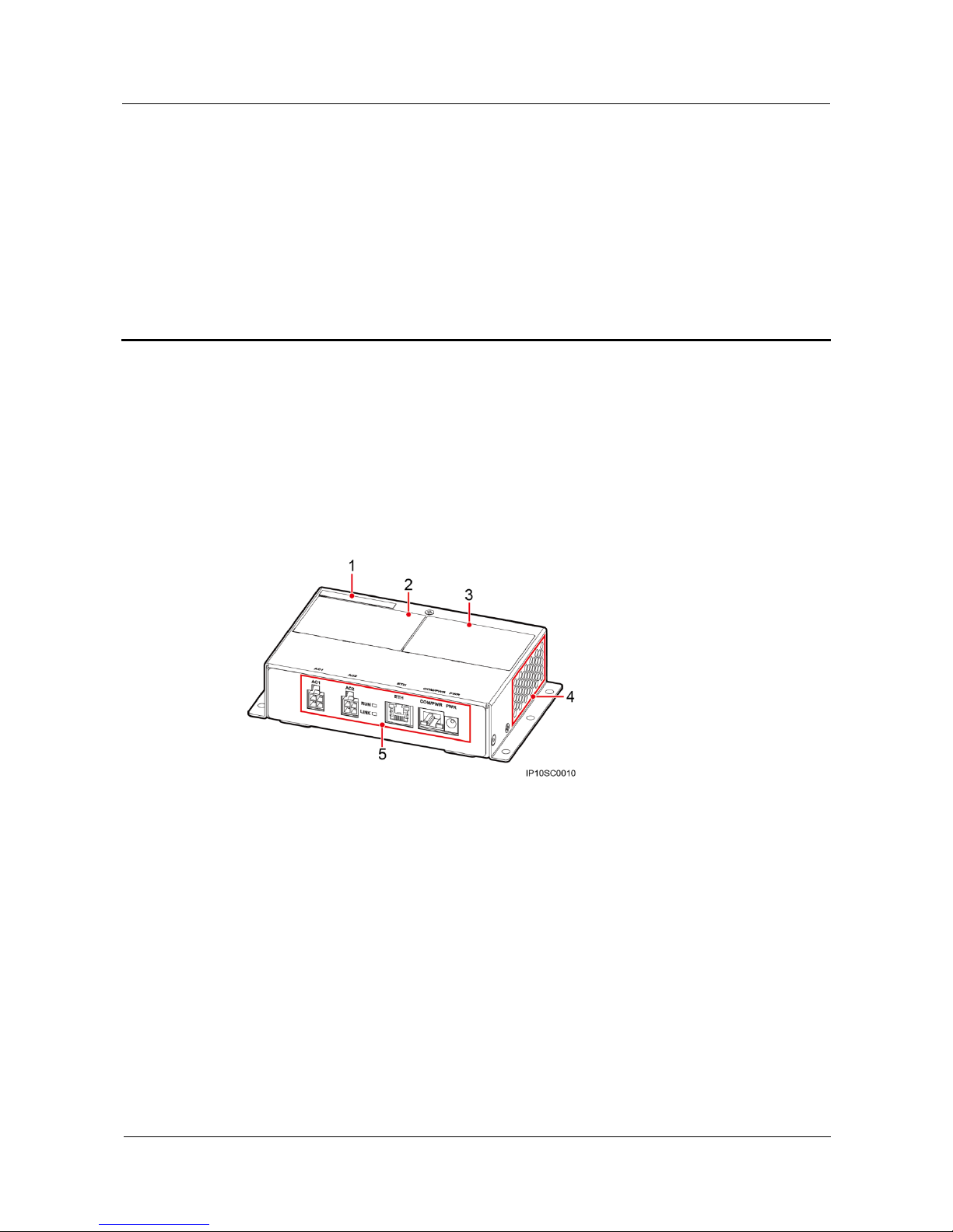
Figure 2-1 shows a PLC CCO.
Figure 2-1 PLC CCO exterior
(1) ESN label
(2) Product label
(3) Qualification certificate
(4) Air exhaust vents
(5) Ports and indicators
Functions
The PLC CCO can connect to SUN2000 inverters that support power line
communication (PLC) functions to transmit data over the power line.
The PLC CCO can connect to the data collector using an RS485 communications cable
to transmit data and convert between PLC and RS485 communication.

PLC CCO01A
User Manual
2 Overview
Issue 02 (2016-01-10)
Huawei Proprietary and Confidential
Copyright © Huawei Technologies Co., Ltd.
4
Benefits
The PLC networking mode uses the existing power line for communication and does not
require additional communications cable, which reduces the construction and maintenance
costs and improves communication reliability and efficiency.
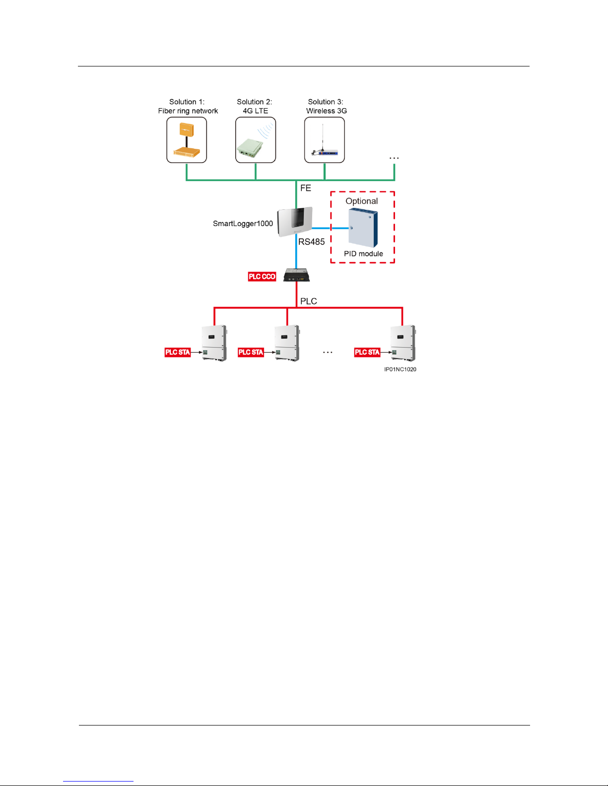
2.2 Networking
A PLC module consists of the station (STA) and central controller (CCO). Figure 2-2 shows
the typical PLC networking.
As the slave unit of the PLC, the STA is installed inside the SUN2000 as a
communications board. The STA converts the RS485 communications data received
from the inverter monitoring board and sends the converted data to the AC power cable.
In addition, it converts the data received from the AC power cable and sends the
converted data to the inverter monitoring board.
As the master unit of the PLC, the CCO is installed in a SUN2000 communication box
or box-type transformer as a standalone device. The CCO converts RS485
communications data received from the data collector and sends the converted data to the
AC power cable. In addition, it converts the data received from the AC power cable and
sends the converted data to the data collector.
The PLC CCO can connect to a maximum of 80 PLC STAs. Generally, a PLC CCO is configured
for each grid-tied point.
The PLC CCO supports only the Modbus RTU protocol.
PLC CCO01A
User Manual
2 Overview
Issue 02 (2016-01-10)
Huawei Proprietary and Confidential
Copyright © Huawei Technologies Co., Ltd.
5
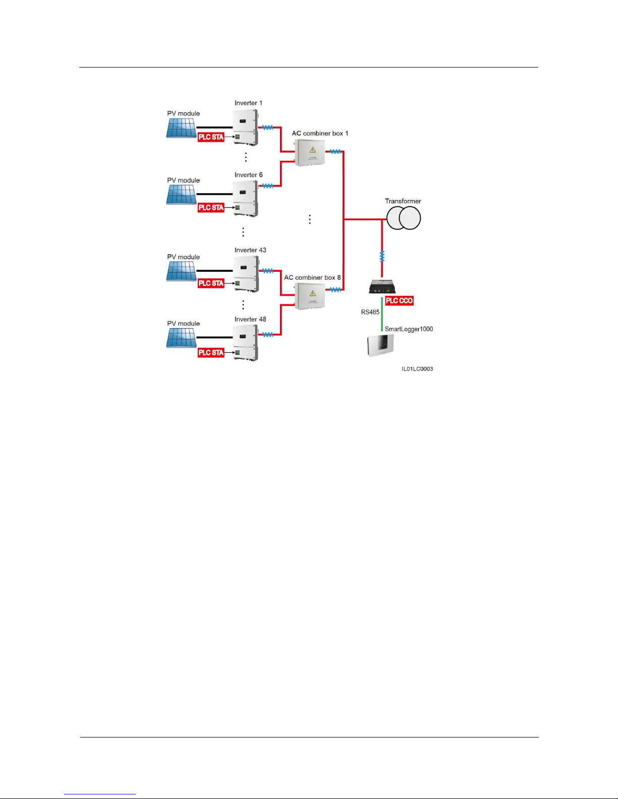
Figure 2-2 PLC networking applied to typical medium-voltage grid-tied scenarios
Figure 2-3 shows the location of the PLC CCO in a PV array network.
PLC CCO01A
User Manual
2 Overview
Issue 02 (2016-01-10)
Huawei Proprietary and Confidential
Copyright © Huawei Technologies Co., Ltd.
6
Figure 2-3 Location of the PLC CCO in a PV array network
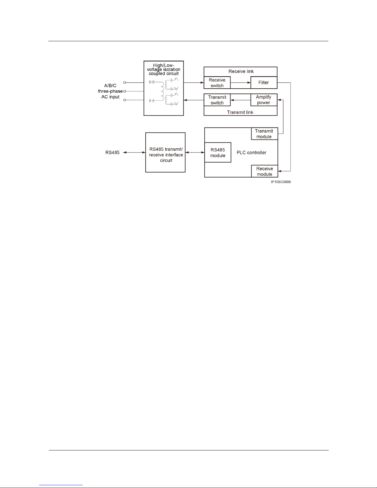
2.3 Working Principles
Figure 2-4 shows the PLC CCO circuit diagram.
PLC CCO01A
User Manual
2 Overview
Issue 02 (2016-01-10)
Huawei Proprietary and Confidential
Copyright © Huawei Technologies Co., Ltd.
7
Figure 2-4 Circuit diagram
The working principles of the PLC CCO are as follows:
Uses the high/low voltage isolation coupled circuit to isolate low-frequency three-phase
AC power from board low voltages, thereby ensuring board safety. In addition, the PLC
CCO provides the high-frequency circuit for injecting and extracting PLC signals.
Filters and processes PLC signals over the receive link. The signals are extracted from
the AC power cable.
Amplifies the power of PLC signals and injects the PLC signals into the AC power cable
over the transmit link.
Converts between PLC and RS485 signals through the PLC controller.
Provides the channel for sending and receiving RS485 signals over the RS485
transmit/receive interface circuit to communicate with the data collector.
PLC CCO01A
User Manual
3 Equipment Installation
Issue 02 (2016-01-10)
Huawei Proprietary and Confidential
Copyright © Huawei Technologies Co., Ltd.
8
3 Equipment Installation
3.1 Checking Before Installation
Before unpacking, check that the product is intact. After unpacking, check that product and
accessories are complete.
Checking Outer Packing Materials
Check the outer packing materials for damage, such as holes and cracks, before unpacking the
PLC CCO. If any damage is found, do not unpack the PLC CCO and contact the supplier or
Huawei technical support promptly.
Checking the Product and Accessories
After unpacking the PLC CCO, check whether the product and accessories are intact and
complete. If any item is missing or damaged, contact the supplier or Huawei technical
support.
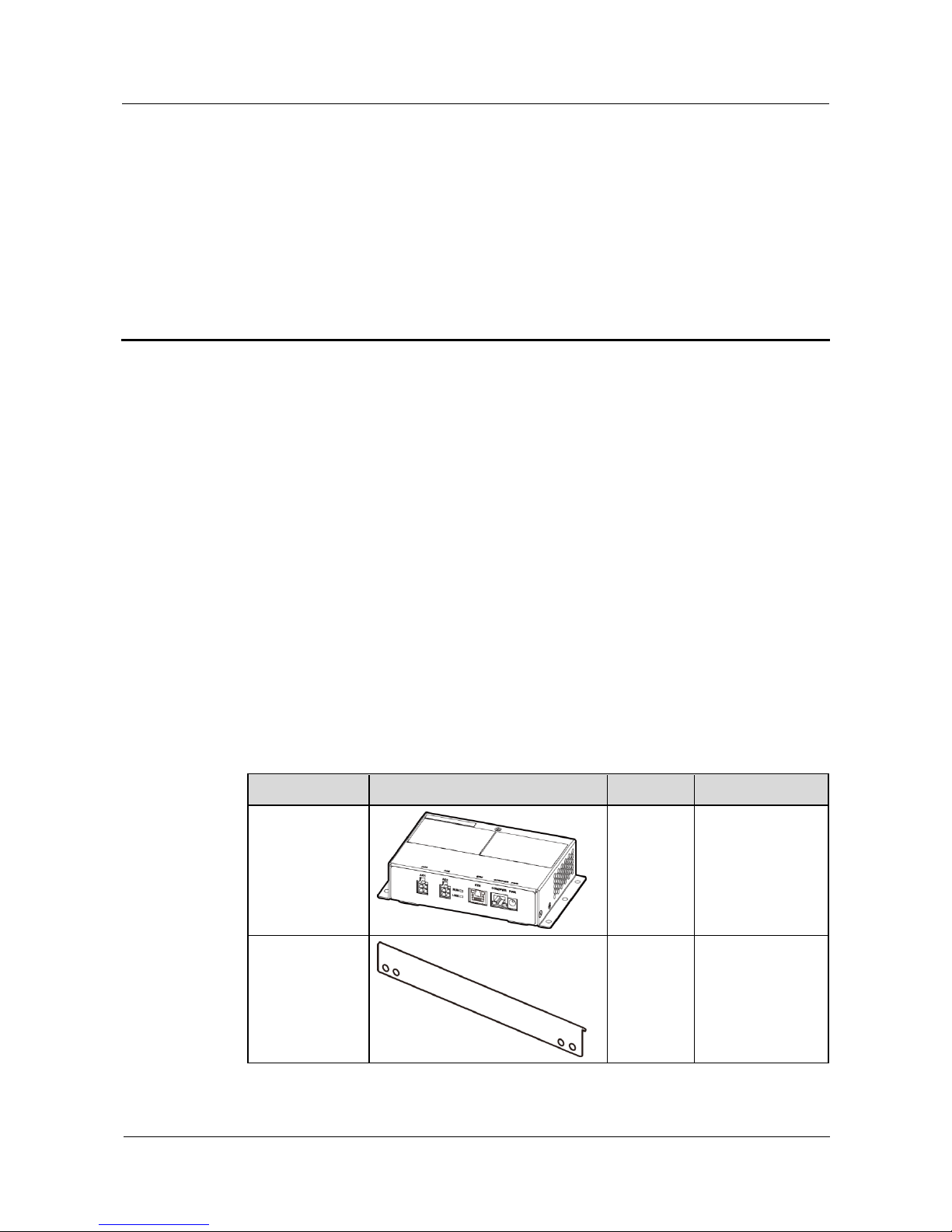
Table 3-1 shows the product and accessories included in the delivery.
Table 3-1 PLC CCO product and accessories
Name
Exterior
Quantity
Description
PLC CCO
1 PCS
N/A
Support 1
1 PCS
Applies when a
guide rail is used
for the installation.
 Loading...