


User Manual
iSiteC ODU3601C CDMA Soft Base Station
System Description
Table of Contents
Table of Contents
Chapter 1 System Overview .................................................................................................1-1
1.1 Introduction...............................................................................................................1-1
1.1.1 Network Solution of cdma2000 1X System........................................................1-1
1.1.2 Market Orientation of ODU3601C......................................................................1-3
1.2 System Feature.........................................................................................................1-3
1.3 Technical Index.........................................................................................................1-4
1.3.1 Engineering Index............................................................................................1-5
1.3.2 Protection Index...............................................................................................1-5
1.3.3 Performance Index...........................................................................................1-5
1.4 External Interface.......................................................................................................1-6
1.4.1 Um Interface....................................................................................................1-6
1.4.2 Baseband Data Interface..................................................................................1-9
1.4.3 Other Interface...............................................................................................1-10
1.5 Reliability Design.....................................................................................................1-10
1.5.1 Hardware Reliability Design............................................................................1-10
1.5.2 Software Reliability Design .............................................................................1-12
Chapter 2 Hardware Architecture.........................................................................................2-1
2.1 Overview...................................................................................................................2-1
2.1.1 Appearance.....................................................................................................2-1
2.1.2 Functional Structure.........................................................................................2-2
2.2 MTRM.......................................................................................................................2-2
2.2.1 Structure and Principle.....................................................................................2-3
2.2.2 External Interface.............................................................................................2-5
2.2.3 Key Index........................................................................................................2-6
2.3 MPAM.......................................................................................................................2-6
2.3.1 Structure and Principle.....................................................................................2-6
2.3.2 External Interface.............................................................................................2-8
2.3.3 Key Index........................................................................................................2-8
2.4 MFEM.......................................................................................................................2-8
2.4.1 Structure and Principle.....................................................................................2-8
2.4.2 External Interface.............................................................................................2-9
2.4.3 Key Index......................................................................................................2-10
2.5 MAPM.....................................................................................................................2-10
2.5.1 Structure and Principle...................................................................................2-10
2.5.2 External Interface...........................................................................................2-11
2.5.3 Key Index......................................................................................................2-11
2.6 MBKP.....................................................................................................................2-11
i

User Manual
iSiteC ODU3601C CDMA Soft Base Station
2.7 Antenna and Feeder Subsystem...............................................................................2-12
System Description
Table of Contents
Chapter 3 System Function..................................................................................................3-1
3.1 RF Functions.............................................................................................................3-1
3.1.1 Power Control..................................................................................................3-1
3.1.2 Handoff...........................................................................................................3-3
3.1.3 Cell Breath ......................................................................................................3-3
3.1.4 Diversity Reception..........................................................................................3-4
3.1.5 Radio Configuration and Channel Support.........................................................3-4
3.2 Maintenance Function................................................................................................3-9
3.3 Lightning Protection.................................................................................................3-10
3.3.1 Lightning Protection for Power Supply.............................................................3-10
3.3.2 Lightning Protection for Antenna and Feeder System.......................................3-11
3.4 Configuration and Networking...................................................................................3-12
3.4.1 Cabinet Configuration.....................................................................................3-12
3.4.2 Site Configuration ..........................................................................................3-13
3.4.3 ODU3601C Networking..................................................................................3-14
Appendix A Performance of Receiver and Transmitter .......................................................A-1
A.1 Performance of Receiver .......................................................................................... A-1
A.1.1 Frequency Coverage ......................................................................................A-1
A.1.2 Access Probe Acquisition................................................................................ A-1
A.1.3 R-TCH Demodulation Performance..................................................................A-1
A.1.4 Receiving Performance................................................................................... A-8
A.1.5 Limitation on Emission.................................................................................... A-9
A.1.6 RSQI .............................................................................................................A-9
A.2 Performance of Transmitter..................................................................................... A-10
A.2.1 Frequency Requirement................................................................................ A-10
A.2.2 Modulation Requirement............................................................................... A-10
A.2.3 RF Output Power Requirement...................................................................... A-11
A.2.4 Limitation on Emission.................................................................................. A-11
Appendix B EMC Performance............................................................................................B-1
B.1 EMI Performance.....................................................................................................B-1
B.2 EMS Performance.................................................................................................... B-2
Appendix C Environment Requirement...............................................................................C-1
C.1 Storage Environment................................................................................................C-1
C.2 Transportation Environment......................................................................................C-2
C.3 Operation Environment.............................................................................................C-4
Appendix D Electromagnetic Radiation...............................................................................D-1
D.1 Introduction..............................................................................................................D-1
D.2 MPE........................................................................................................................D-1
D.3 Estimation of Exposure to Electromagnetic Field........................................................D-3
D.4 Calculation of Safe Distance.....................................................................................D-3
ii

User Manual
iSiteC ODU3601C CDMA Soft Base Station
D.4.1 S = power density [W/m2] see also MPE Limits.................................................D-4
System Description
Table of Contents
D.5 Location of BTS Antenna..........................................................................................D-4
D.5.1 Exclusion Zone...............................................................................................D-4
D.5.2 Guidelines on Selecting Antenna Location .......................................................D-4
Appendix E Standard Compliance.......................................................................................E-1
E.1 General Technical Specification................................................................................ E-1
E.2 Um Interface............................................................................................................ E-1
E.3 Abis Interface...........................................................................................................E-1
E.4 Lightning Protection.................................................................................................. E-2
E.5 Safety...................................................................................................................... E-3
E.6 EMC........................................................................................................................E-3
E.7 Environment.............................................................................................................E-5
Appendix F Abbreviation..................................................................................................... F-1
F.1 Abbreviation of Modules............................................................................................ F-1
F.2 Glossary.................................................................................................................. F-1
iii

User Manual
iSiteC ODU3601C CDMA Soft Base Station
Chapter 1 System Overview
System Description
Chapter 1 System Overview
1.1 Introduction
The Mobile Communication System has experienced the first generation (analog
system) and the second generation (digital system). As the one of the main
development trends of the second generation, cdma2000 1X mobile communication
system has been widely used for commercial purpose.
This section first introduces the network solution of Huawei cdma2000 1X mobile
communication system, and then the market orientation of Huawei base station
ODU3601C.
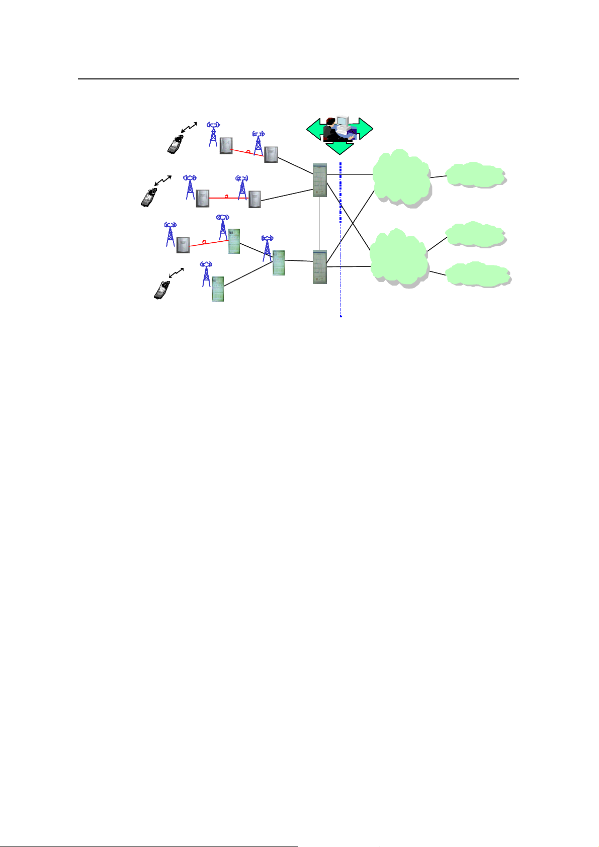
1.1.1 Network Solution of cdma2000 1X System
The cdma2000 1X mobile communication system comprises the Base Station
Subsystem (BSS) and the Core Network (CN).
The BSS comprises the Base Transceiver Station (including ODU3601), Base Station
Controller (BSC), and Packet Control Function (PCF) which is usually integrated with
BSC.
The CN comprises the packet domain network and circuit domain network. The
equipment of packet domain interworks with Internet, and that of the circuit domain
interworks with the conventional PLMN and PSTN/ISDN.
The system's operation and maintenance is implemented via Huawei integrated
mobile network management system iManager M2000.
Position of ODU3601C in the network is shown in Figure 1-1.
1-1
User Manual
iSiteC ODU3601C CDMA Soft Base Station
MS
MSMS
MS
MSMS
MS
MSMS
ODU3601C
ODU3601CODU3601C
ODU3601C
ODU3601CODU3601C
ODU3601C
ODU3601CODU3601C
cBTS3612
cBTS3612cBTS3612
cBTS3612
cBTS3612cBTS3612
BTS3601C
BTS3601CBTS3601C
MS: Mobile Station BSC: Base Station Controller
ISDN: Integrated Services Digital Network PLMN: Public Land Mobile Network
PSTN: Public Switched Telephone Network PCF: Packet Control Function
BSS: Base Station Subsystem CN: Core Network
Mobile integrated
Mobile integrated
management system
management system
BTS3601C
BTS3601CBTS3601C
BSC/PCF
BSC/PCF
Abis
Abis
Abis
Abis
A3/A7
A3/A7
cBTS3612
cBTS3612cBTS3612
Abis
Abis
BSC/PCF
BSC/PCF
BSS CN
BSS CN
A10/A11
A10/A11
A10/A11
A10/A11
A1/A2
A1/A2
A1/A2
A1/A2
System Description
Chapter 1 System Overview
Packet domain
Packet domain
network equipment
network equipment
Circuit domain
Circuit domain
network equipment
network equipment
Internet
Internet
PLMN
PLMN
PSTN/ISDN
PSTN/ISDN
Figure 1-1 Network structure of Huawei cdma2000 1X mobile communication system
l ODU3601C
ODU3601C is an outdoor one-carrier soft base station. It shares the baseband
processing resource and main control clock resource with its upper-level BTS. It
implements radio signal transmission and reception together with the upper-level BTS
under the control of BSC.
l BTS3601C
BTS3601C is an outdoor one-carrier BTS. It transmits/receives radio signals so as to
realize the communication between the radio system and the Mobile Station (MS).
l cBTS3612
cBTS3612 is a set of indoor BTS equipment. The maximum capacity of single cabinet
contains 12 sector carriers. Same with BTS3601C, it also transmits/receives radio
signals to accomplish the communication between the radio system and the MS.
l Base Station Controller (BSC)
BSC performs the following functions: BTS control and management, call connection
and disconnection, mobility management, power control, and radio resource
management. It provides stable and reliable radio connections for the upper-level
services through soft/hard handoff.
l Packet Control Function (PCF)
PCF is used for the management of Radio-Packet (R-P) connection. As radio
resources are limited, they should be released when subscribers are not sending or
1-2

User Manual
iSiteC ODU3601C CDMA Soft Base Station
receiving information, but the Point-to-Point Protocol (PPP) connection must be
maintained. PCF shields the radio mobility against the upper-level services through
the handoff function.
l Mobile Station (MS)
MS is a set of mobile subscriber equipment that can originate and receive calls, and
can communicate with BTS.
1.1.2 Market Orientation of ODU3601C
Huawei ODU3601C is fully compatible with IS-95A/B and IS-2000 standards.
As illustrated in Figure 1-1, ODU3601C is located between other BTS (such as
BTS3601C and cBTS3612) and the MS. It is connected to the upper-level BTS
(master BTS) with optical fibers, equivalent to the function of the Radio Frequency
(RF) module of the upper-level BTS installed far away.
ODU3601C is an outdoor base station, configured with only one carrier. It features
small size, easy installation, flexible networking, less investment and fast network
construction. ODU3601C can be used in residential quarters and urban hot spots /
blind spots, and provide small-capacity wide-coverage for remote areas (such as rural
area, grassland, highway, scenic spots).
System Description
Chapter 1 System Overview
ODU3601C shares the clock resource of the upper-level BTS, so no satellite antenna
is needed. This feature makes ODU3601C an attractive application in indoor and
underground environment where the installation of satellite antenna is difficult.
1.2 System Feature
I. Easy installation
Featuring small size, light weight and mains supply, ODU3601C does not require an
equipment room or air conditioner. It neither requires a special tower as it can be
easily installed on a metal post, stayed tower or on the wall. All these can reduce the
site construction cost without affecting the network quality.
II. Wide application scope
ODU3601C is dust-proof, anti-burglary, water-proof, and damp-proof. With its
protection performance in compliance with the IP55 (IEC 60529: Degrees of
protection provided by enclosure), it operates normally in different whether conditions.
1-3

User Manual
iSiteC ODU3601C CDMA Soft Base Station
III. Flexible coverage schemes
ODU3601C shares the baseband subsystem of master BTS for service processing.
The I/Q digital modulated signals are transmitted between the ODU3601C and the
master BTS through the optical fibers. ODU3601C supports various cascading
methods with the master BTS to achieve flexible network coverage.
The cascading distance can be either 10km or 70km, depending on the optical
interface module used. For BTS3601C, total two ODU3601Cs can be cascaded, and
the second ODU3601C can be placed 60km away. For cBTS3612, total six
ODU3601Cs can be cascaded, and the sixth ODU3601C can be placed 90km away.
IV. Synchronization within the whole network
By adopting the automatic delay compensation technique developed by Huawei, the
master BTS provides ODU3601C with precise clock synchronization signals via
optical fibers. No GPS antenna is needed. This ensures synchronization within the
whole network and lowers call drop ratio during handoffs.
System Description
Chapter 1 System Overview
V. Unified network planning
Though a logical base station, ODU3601C can be regarded as a normal entity in
network planning, as it can be upgraded to be an independent cBTS3601C by adding
the Micro-bts Baseband Processing Module (MBPM).
VI. Softer handoff
ODU3601C and the master BTS may cover neighboring cells. As the baseband
processing of ODU3601C is implemented by the resource pool of the master BTS,
the co-frequency handoff between the ODU3601C and the master BTS is the softer
handoff.
VII. Support for multi-bands
ODU3601C supports 450MHz and 800MHz bands, therefore, it can be applied in the
450MHz communication system and the 800MHz communication system.
1.3 Technical Index
The technical indices include engineering, protection and performance indices.
The engineering indices include power supply, power consumption, weight,
dimensions and other indices involved in engineering installation.
The protection indices refer to the capabilities of the main external interfaces agains t
surge current.
1-4

User Manual
iSiteC ODU3601C CDMA Soft Base Station
The performance indices refer to the technical parameters of its receiver/transmitter
and the reliability indices of the whole system.
System Description
Chapter 1 System Overview
1.3.1 Engineering Index
Power supply
Power consumption
Weight
Operation environment
Cabinet dimensions
(height%width%depth)
1.3.2 Protection Index
E1 interface
RF feeder interface
AC power supply interface
(for connecting AC lightning
protection box)
Satellite feeder interface (for
connecting lightning arrestor
for satellite feeder)
~220V (150~300V AC)
<300W (In normal temperature, while the heating plate is not working)
<500W (In low temperature, while the heating plate is working)
<40kg
Temperature: -40âC~55âC
Relative humidity 5%~100%
700mm%450mm%330mm
Differential mode 5kA, or common mode 10kA surge current
Differential mode 8kA, or common mode 8kA surge current
Differential mode 40kA, or common mode 40kA surge current
Differential mode 8kA, or common mode 8kA surge current
1.3.3 Performance Index
I. Transmission
l 450MHz band
Working frequency
Channel bandwidth
Channel precision
Frequency tolerance Ÿ!
l 800MHz band
Transmit power
460~470MHz
1.23MHz
25kHz
0.05ppm
20W (the maximum value measured at the cabinet-top feeder port)
1-5

User Manual
iSiteC ODU3601C CDMA Soft Base Station
Frequency coverage
Channel bandwidth
System Description
Chapter 1 System Overview
869Ã894MHz
1.23MHz
Channel step length
Frequency tolerance Ÿ!
Transmit power
II. Reception
l 450MHz band
Signal receiving sensitivity
Working frequency
Channel bandwidth
Channel precision
l 800MHz band
Working frequency
Channel bandwidth
Channel step length
30kHz
0.05ppm
20W (the maximum value measured at the cabinet-top feeder port)
450Ã460MHz
1.23MHz
25kHz
-127dBm (RC3, and main and diversity reception)
824Ã849MHz
1.23MHz
30kHz
Signal receiving sensitivity
III. System reliability
Mean Time Between Failures
(MTBF)
Mean Time To Repair (MTTR) Ÿ
Availability ¦
1.4 External Interface
1.4.1 Um Interface
I. Overview
In Public Land Mobile Network (PLMN), MS is connected with the fixed part of the
network through the radio channel. The radio channel allows the subscribers to be
connected with the network and to enjoy telecommunication services.
-128dBm (RC3, and main and diversity reception)
100,000 hour
¦
1 hour
99.999%
1-6
User Manual
iSiteC ODU3601C CDMA Soft Base Station
To implement interconnection between MS and BSS, systematic rules and standards
should be established for signal transmission on radio channels. The standard for
regulating radio channel signal transmission is called radio interface, or Um interface.
Um interface is the most important interface among the many interfaces of CDMA
system. Firstly, standardized radio interface ensures that MSs of different
manufacturers are fully compatible with different networks. This is one of the
fundamental conditions for realizing the roaming function of CDMA system. Secondly,
radio interface defines the spectrum availability and capacity of CDMA system.
Um interface is defined with the following features:
l Channel structure and access capacity.
l Communication protocol between MS and BSS.
l Maintenance and operation features.
l Performance features.
l Service features.
II. Um interface protocol model
System Description
Chapter 1 System Overview
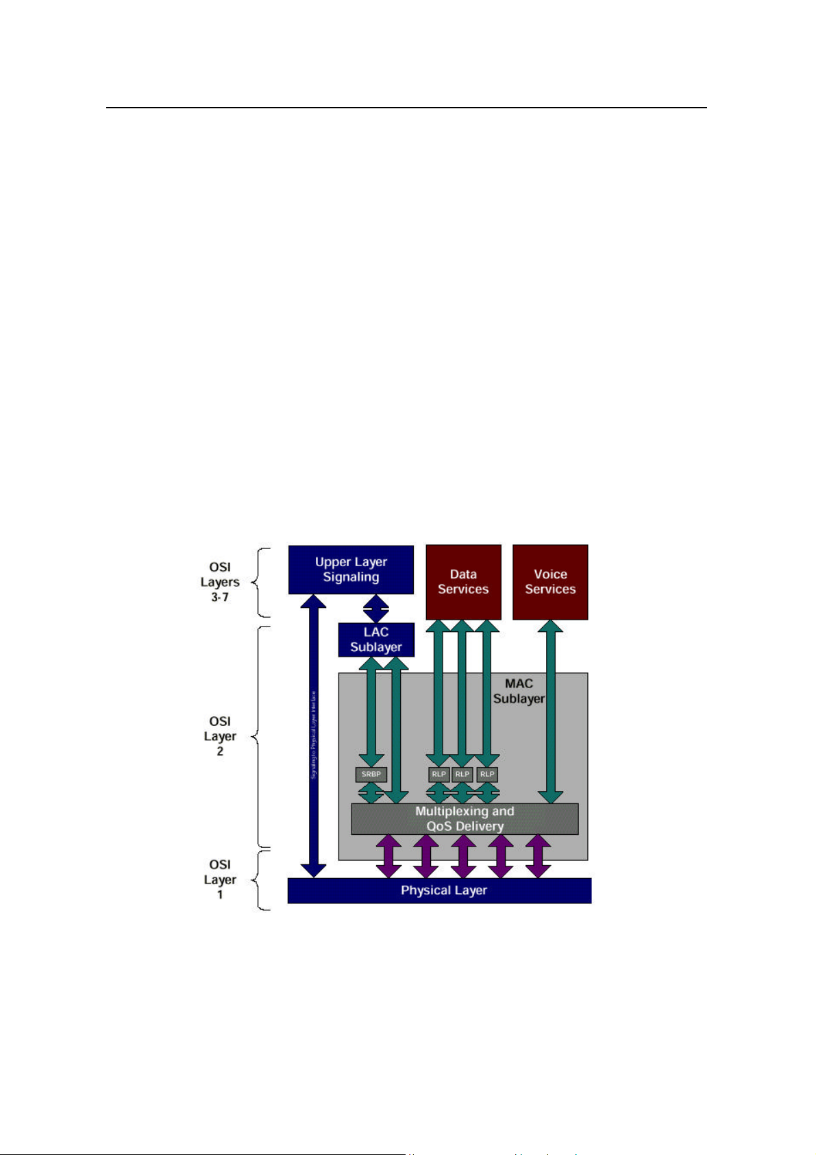
Um interface protocol stack is in 3 layers, as shown in Figure 1-2.
Figure 1-2 Um interface layered structure
Layer 1 is the physical layer, that is, the bottom layer. It includes various physical
channels, and provides a basic radio channel for the transmission of higher layer
information.
1-7

User Manual
iSiteC ODU3601C CDMA Soft Base Station
Layer 2 is the data link layer, including Medium Access Control (MAC) sublayer and
Link Access Control (LAC) sublayer. The MAC sublayer performs the mapping
between logical channels and physical channels, and provides Radio Link Protocol
(RLP) function. The LAC sublayer performs such functions as authentication,
Automatic Repeat Request (ARQ), addressing and packet organization.
Layer 3 is the top layer. It performs Radio Resource Management (RM), Mobility
Management (MM) and Connection Management (CM) through the air interface.
III. Physical layer
1) Working band
Band Forward band Reverse band Duplex spacing Channel width Carrier spacing
450MHz 460 - 470MHz 450 - 460MHz 10MHz 1.23 MHz 1.25 MHz
800MHz 869 - 894 MHz 824 - 849 MHz 45MHz 1.23 MHz 1.23 MHz
2) Physical layer function
l Service bearer: the physical channel in the physical layer provides bearer for the
logical channel of the higher layer.
l Bit error check: the physical layer provides transmission service with error
protection function, including error checking and error correction.
l User identification: the physical layer provides an exclusive ID for every user by
code division.
3) Radio configuration
System Description
Chapter 1 System Overview
The physical layer supports multiple Radio Configurations (RCs). Different RCs
support different traffic channel data rates. For detailed introduction, please refer to
Section 3.1.5 Radio Configuration and Channel Support.
IV. Data link layer
Data link layer at Um interface includes two sublayers, MAC and LAC. The purpose of
introducing MAC and LAC is to:
l Support higher level services (signaling, voice, packet data and circuit data).
l Support data services of multiple rates.
l Support packet data service and circuit data service of higher quality (QoS).
l Support multi-media service, that is, processing voices, packet data and circuit
data of different QoS levels at the same time.
1) MAC sublayer
To support data service and multi-media service, cdma2000 1X provides powerful
MAC layer to ensure the reliability of services. MAC layer provides two important
functions:
l Radio Link Protocol (RLP), ensuring reliable transmission on the radio link.
1-8

User Manual
iSiteC ODU3601C CDMA Soft Base Station
l Multiplex function and QoS function, with diversified services and higher service
quality.
2) LAC sublayer
LAC layer performs such functions as Automatic Repeat Request (ARQ),
authentication and addressing.
V. Layer 3
The higher layer signaling performs the functions such as radio resource
management, mobility management and call connection management on air
interface.
1) Radio resource management
The radio resource management functions include:
l Radio channel management
It is used to establish, operate and release radio channels, and help to realize soft
handoff, softer handoff and hard handoff.
System Description
Chapter 1 System Overview
l Power control
Various power control technologies are used on Um interface to reduce the system
interference and improve the system capacity.
2) Mobility management
It is used to support the mobility features of the mobile subscriber, performing such
functions as registration, authentication and Temporary Mobile Subscriber Identity
(TMSI) re-allocation.
3) Connection management
It is used to setup, maintain and terminate calls.
1.4.2 Baseband Data Interface
ODU3601C communicates with the upper-level BTS through the baseband
processing interface.
This interface adopts optical fibers to transmit I/Q digital modulated signals, and
supports various cascading modes. For details, please refer to Section 1.2 System
Feature.
The baseband data interface adopts automatic delay compensation technique. The
precise clock synchronization signal is provided by the master BTS through the
optical fiber.
1-9

User Manual
iSiteC ODU3601C CDMA Soft Base Station
1.4.3 Other Interface
I. Test interface
The test interface provides 10MHz and 2s signals through MTRM that may be needed
for test instruments.
II. Power supply interface
ODU3601C supports 220V AC power supply. It provides external 220V AC interface
and 24V DC battery interface.
1.5 Reliability Design
Reliability design of a system is shown in the stability and reliability of the product
during operation.
Huawei ODU3601C is designed based on the following standards:
System Description
Chapter 1 System Overview
l TIA/EIA/IS-95A CDMA Radio Interface Specifications
l TIA/EIA/IS-95B CDMA Radio Interface Specifications
l TIA/EIA/IS-2000 CDMA Radio Interface Specifications
l TIA/EIA/IS-97D CDMA Base Station Minimum Performance Standard
l Huawei product reliability design index and related technical specifications
With various measures taken, the design of boards is in strict accordance with the
requirement of above standards pertaining to reliability.
1.5.1 Hardware Reliability Design
I. De-rating design
To improve system reliability and prolong the service life of components, components
are carefully selected and strictly tested, and less stress (electrical stress and
temperature stress) is to be borne in actual operation than its designed rating.
II. Selection and control of component
The category, specifications and manufacturers of the components are carefully
selected and reviewed according to the requirements of the product reliability and
maintainability. The replace ability and normalization of components is one of the
main factors for the decision, which help to reduce the types of components used and
hence improve the availability of the system.
1-10

User Manual
iSiteC ODU3601C CDMA Soft Base Station
III. Board level reliability design
Many measures have been taken in board design to improve its reliability.
Redundancy configuration is applied for key components to improve system reliability.
l Key circuits are designed by Huawei, which lays the foundation of high reliability.
l The hardware WATCHDOG is equipped for the board, and the board can
automatically reset in case of fault.
l The board is provided with the functions of over-current and over-voltage
protection and the function of temperature detection.
l Strict thermal analysis and simulation tests are conducted during the design of
boards for the purpose of ensuring longtime operation.
l The board software and important data is stored in the non-volatile memory, so
that the board can be restarted when software upgrading fails.
IV. Fault detection, location and recovery
The BTS system is equipped with the functions of self-detection and fault diagnosis
that can record and output various fault information. Common software and hardware
faults can be corrected automatically.
System Description
Chapter 1 System Overview
The hardware fault detection functions include fault locating, isolating and automatic
switchover. The maintenance engineers can identify the faulty boards easily with the
help of the maintenance console.
The ODU3601C system also supports the reloading of configuration data files and
board execution programs.
V. Fault tolerance and exceptional protection
When faults occur, the system usually will not be blocked.
The system will make a final confirmation on a hardware fault through repeated
detection, thus avoiding system reconfiguration or QoS deterioration due to
contingent faults.
VI. Thermal design
The influence of temperature on the ODU3601C has been considered in the design.
Thermal design primarily concerns the selection of components, circuit design
(including error tolerance, drift design and derating design), structure design and heat
dissipation, so that the ODU3601C can work reliably in a wide range of temperatures.
The first consideration in thermal design is to balance the heat distribution of the
system. Corresponding measures are taken in the place where heat is more likely to
be accumulated.
1-11

User Manual
iSiteC ODU3601C CDMA Soft Base Station
VII. Maintainability
The purpose of maintainability design is to define the workload and nature of the
maintenance, so as to cut the maintenance time. The main approaches adopted
include standardization, modularization, error prevention, and testability improvement,
which can simplify the maintenance work.
VIII. EMC design
The design ensures that ODU3601C will not degrade to an unacceptable level due to
the electromagnetic interference from other equipment in the same electromagnetic
environment. Neither the ODU3601C will cause other equipment in the same
electromagnetic environment to degrade to an unacceptable level.
IX. Lightning protection
To eliminate the probability of lightning damage on the ODU3601C system, proper
measures are taken with respect to the lightning protection for DC power supply and
antenna & feeder system. For details, please refer to "3.3 Lightning Protection".
System Description
Chapter 1 System Overview
1.5.2 Software Reliability Design
Software reliability mainly includes protection performance and fault tolerance
capability.
I. Protection performance
The key to improve software reliability is to reduce software defects. Software
reliability of ODU3601C is ensured through the quality control in the whole process
from system requirement analysis, system design to system test.
Starting from the requirement analysis, software development process follows the
regulations such as Capability Mature Mode (CMM), which aim to control faults in the
initial stage.
In software design, much attention is devoted to the designing method and
implementation: the software is designed in a modular structure, and in a loose
coupling mechanism. When a fault occurs to one module, other modules will not be
affected. In addition, preventive measures such as fault detection, isolating and
clearing are also applied to improve the system reliability. Other effective methods
include code read-through, inspection, and unit test.
Various software tests are conducted to improve the software reliability. Test
engineers participate the whole software development process, from unit test to
system test. They make plans strictly following the demand of the upper -level flow,
1-12

User Manual
iSiteC ODU3601C CDMA Soft Base Station
which ensure the improvement of software reliability. Additionally, test plans are
modified and improved with the tests.
II. Fault toler ance capability
Fault tolerance capability of the software system me ans that the whole system would
not collapse when a minor software fault occurs. That is, the system has the
self-healing capability. The fault tolerance of BTS3601 software is represented in the
following aspects:
l All boards work on a real-time operating system of high reliability.
l If software loading fails, the system can return to the version that was
successfully loaded last time.
l Important operations are recorded in log files.
l Different authority levels are provided for operations, so as to prevent users from
performing unauthorized operations.
l Warnings are given for the operations that will cause system reboot (such as
reset operation). The operator is required to confirm such operations.
System Description
Chapter 1 System Overview
1-13
User Manual
iSiteC ODU3601C CDMA Soft Base Station
Chapter 2 Hardware Architecture
System Description
Chapter 2 Hardware Architecture
2.1 Overview
2.1.1 Appearance
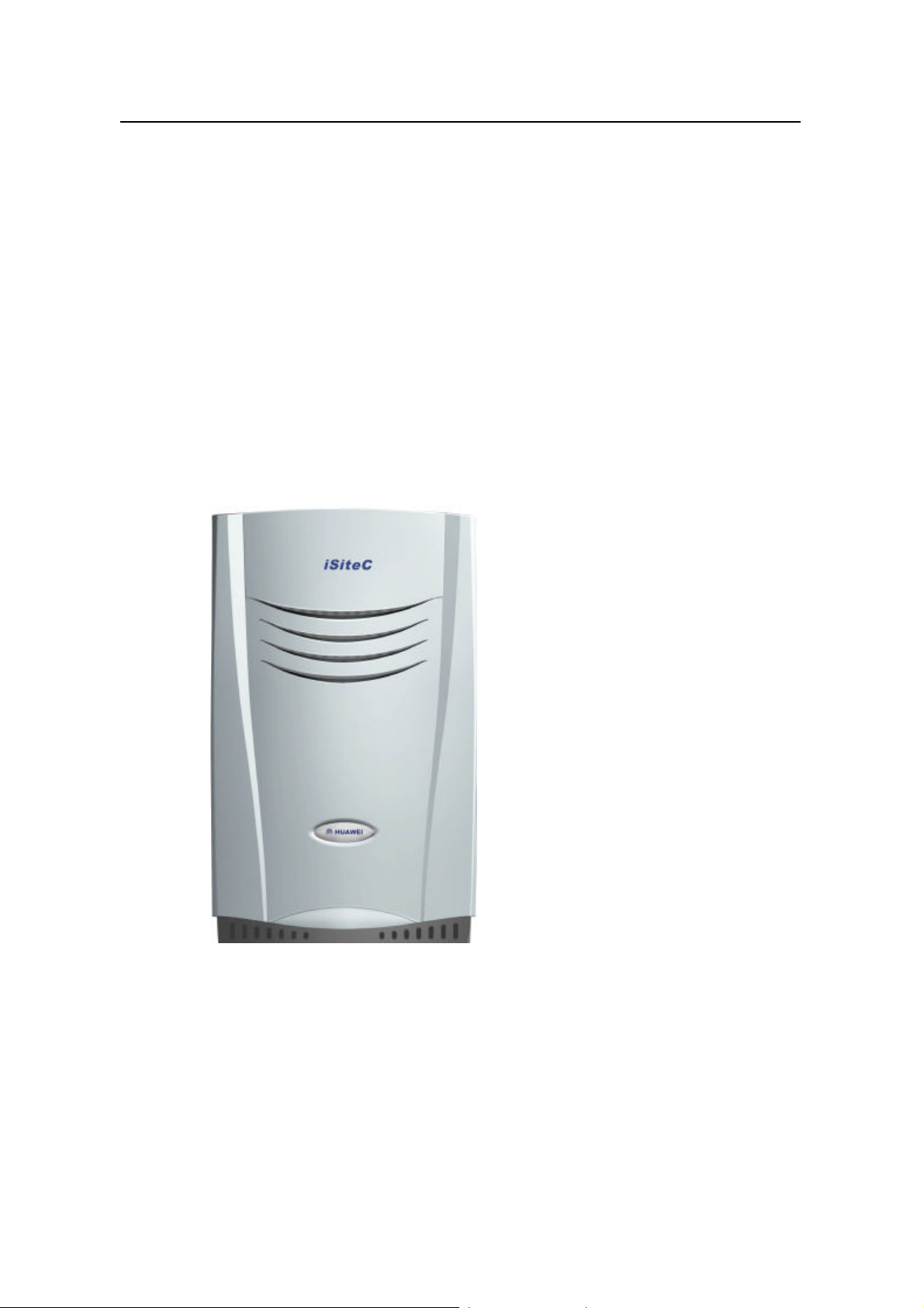
I. Cabinet appearance
Figure 2-1 shows the appearance of an ODU3601C cabinet. The cabinet dimensions
are: 700mm % 450mm % 330mm (height % width % depth).
Figure 2-1 ODU3601C cabinet
II. Cabinet feature
l Excellent electrical conductivity and shielding effect.
l Equipped with thermal tube for heat exhaustion, free of noise
l Water-proof, sun-screening, anti-burglary features make it suitable for outdoor
installation.
2-1
User Manual
iSiteC ODU3601C CDMA Soft Base Station
l Small size, light weight and attractive appearance.
l Modular structure, making installation and maintenance easy.
System Description
Chapter 2 Hardware Architecture
2.1.2 Functional Structure
The ODU3601C has a compact and highly integrated structure. It consists of
Micro-bts Transceiver Module (MTRM), Micro-bts Power Amplifier Module (MPAM),
Micro-bts Radio Frequency Front End Module (MFEM), Micro-bts Ac-dc Power supply
Module (MAPM), and the antenna & feeder system.
The functional structure is shown in Figure 2-2.
Optical
BTS
or
ODU3601C
ODU3601C
220VAC
MTRB: Micro-bts Transceiver Board MTRM: Micro-bts Transceiver Module
MPAU: Micro-bts Power Amplifier Unit MMCB: Micro-bts Monitor & Control Board
MPAM: Micro-bts Power Amplifier Module MAPM: Micro-bts Ac-dc Power Supply Module
MRDU: Micro-bts Divide And Duplexer Receive Filter Unit MFEM: Micro-bts Radio Frequency Front End Module
MLNA: Micro-bts Low-Noise Amplifier
fier
Optical
fier
Heating plate
MTRB
MTRM
MAPM
RS485
+27VDC
RS-485
TX
RXM
RXD
MPAU
MPAM
MMCB
MFEM
Um
Tx
Rx
MRDUMLNA
Figure 2-2 Functional structure of ODU3601C
ODU3601C performs the functions of RF signal transceiving and amplification, and
the conversion of baseband signals. The functions of various modules are detailed in
the following sections.
2.2 MTRM
Micro-bts Transceiver Module (MTRM) consists of MTRB and heating plate.
The heating plate ensures that MTRB can start and operate normally in low
temperature.
MTRB modulates/demodulates baseband I/Q signals, performs up/down conversion,
and supports the function of cascading via optical fiber.
2-2
User Manual
iSiteC ODU3601C CDMA Soft Base Station
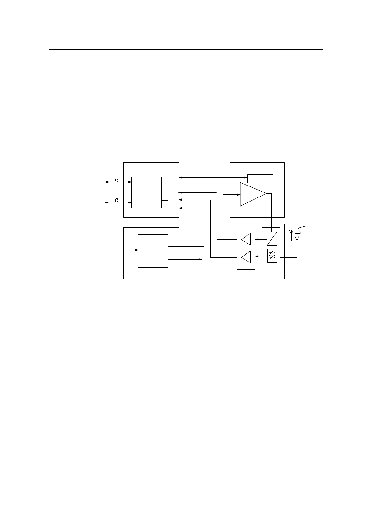
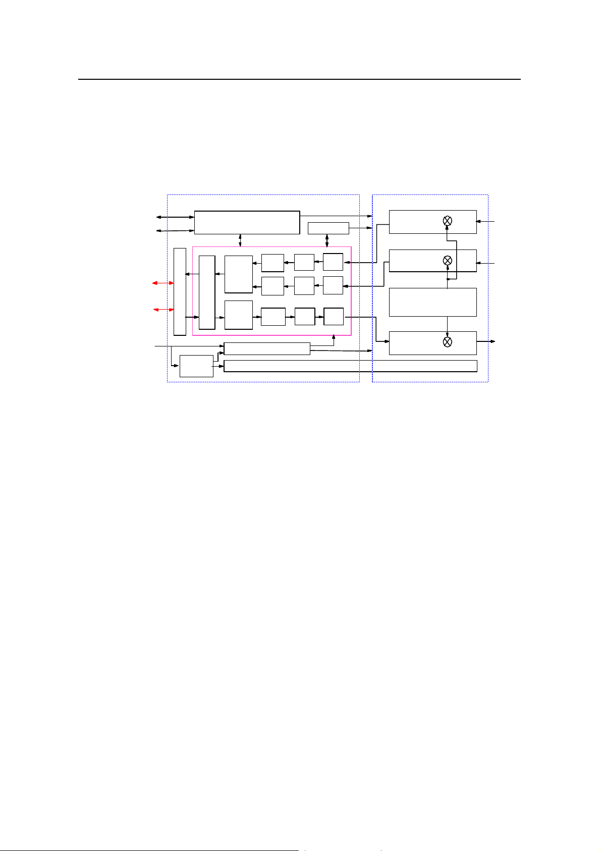
2.2.1 Structure and Principle
MTRM consists of Micro-bts Intermediate Frequency Unit (MIFU) and Micro-bts Radio
up-down Converter Unit (MRCU).
The functional structure is shown in Figure 2-3.
System Description
Chapter 2 Hardware Architecture
MRCU
MRCU
Main receiver
Main receiver
Diversity receiver
Diversity receiver
Local oscillator
Local oscillator
Transmiter
Transmiter
MPAM
MPAM
MAPM
MAPM
BTS
or
ODU3601C
ODU3601C
ODU3601C
MAPM
MAPM
MIFU
MIFU
RS485
RS485
RS485
RS485
Optical interface sub-unit
Optical interface sub-unit
+27V
+27V
Control
Control
sub-unit
sub-unit
CPU
CPU
FIR
FIR
&
&
DAGC
DAGC
Section multiplexer
Section multiplexer
FIR
FIR
Down
Down
converter
converter
Down
Down
converter
converter
Up
Up
converter
converter
MAPM
MAPM
Clock sub-unit
Clock sub-unit
ADC
ADC
ADC
ADC
DAC
DAC
Filter
Filter
Filter
Filter
Filter
Filter
Heating plate
Heating plate
Figure 2-3 Functional structure of MTRM
I. MIFU
MIFU consists of up converter, down converter, multiplexer/demultiplexer, optical
interface, clock, CPU, and power supply sub-units. It is in charge of the conversion
between analog intermediate frequency signals and digital baseband signals, and the
control of MTRB.
MFEM
MFEM
MFEM
MFEM
MHPA
MHPA
l Up converter
The up converter accomplishes wave filtering, digital up conversion and digital-analog
conversion of the signals in the transmit path.
On receiving the baseband I/Q signals that have been de-multiplexed, it performs
digital up conversion after baseband filtering. Then the digital intermediate frequency
signals are converted into analog intermediate frequency signals after digital-analog
conversion and wave filtering. At last, the analog intermediate frequency signals are
sent to the transmitter in MRCU through Radio Frequency (RF) interface.
l Down converter
The down converter accomplishes the analog-digital conversion, digital down
conversion and baseband filtering of the signals in the receive path.
2-3

User Manual
iSiteC ODU3601C CDMA Soft Base Station
On receiving the analog intermediate frequency signals from the radio interface, it
converts them into digital intermediate frequency signals via analog-digital conversion.
Then the digital intermediate frequency signals are converted into baseband I/Q
signals via digital down conversion and baseband filtering. As last, the I/Q signals are
transmitted to the demultiplexer/multiplexer.
l Demultiplexer/multiplexer
Under the control of the CPU, the demultiplexer/multiplexer de-multiplexes the
forward I/Q signals, and multiplexes the reverse I/Q signals. At the same time, it
multiplexes/de-multiplexes the Operation & Maintenance (O&M) signals of the OML.
l Optical interface sub-unit
This sub-unit consists of two optical interface modules. The optical interface modules
perform channel coding/decoding, and accomplish optical-electrical and
electrical-optical signal conversion. They are respectively connected with upper-level
BTS (or ODU3601C) and the lower-level ODU3601C to realize optical fiber
cascading.
System Description
Chapter 2 Hardware Architecture
If the upper-level BTS is cBTS3612, this optical interface sub-unit is connected to the
BTS Resource Distribution Module (BRDM) optical interface of cBTS3612. If the
upper-level BTS is BTS3601C or ODU3601C, it is connected to the Micro-bts
Transceiver Module (MTRM) optical interface of BTS3601C or ODU3601C.
l Clock sub-unit
The clock sub-unit generates all the clocks needed by MIFU, including the clocks for
up/down conversion, analog-digital conversion (ADC), and digital-analog conversion
(DAC). At the same time, it also provides the reference clock for the MRCU.
l CPU
The CPU is in charge of the control of MTRB, including the initialization upon
power-on, alarm collecting and reporting, and processing related O&M messages.
The O&M messages are received from or sent to the upper-level BTS by the
multiplex/demultiplex sub-unit of the digital MIFU.
l Control sub-unit and heating plate
The control sub-unit and the heating plate enable MTRM to start and normally
operate in low temperature.
When the internal module temperature is lower than -5âC, the heating plate will be
first started to heat the module. Other boards of the module will not be powered
unless the module temperature rises to the set value.
l Power supply sub-unit
With input voltage of +27V, the power supply sub-unit provides power to MIFU and
MRCU.
2-4

User Manual
iSiteC ODU3601C CDMA Soft Base Station
II. MRCU
MRCU consists of transmitter, main/diversity receiver and local oscillator. It
up-converts, amplifies, and performs spurious-suppressive wave filtering for the
intermediate frequency signals output by MIFU. It also performs analog
down-conversion, amplification, channel-selective wave filtering and receiving noise
factor control over the main/diversity receiving signal input from the MFEM.
l Transmitter
On receiving the modulated analog intermediate frequency signals output by MIFU,
the transmitter converts them to specified RF band after two times of up conversions.
Before and after the up conversion, wave filtering, signal amplification and power
control are performed so as to ensure that the output RF signals meet the protocol
requirements on power level, Adjacent Channel Power Radio (ACPR) and
spuriousness.
l Main/diversity receiver
The main/diversity receiver converts the RF signals output by MFEM to specified
intermediate frequency signals via down conversion, and performs wave filtering,
signal amplification and power control before and after the down conversion, so as to
ensure that the intermediate frequency signals output can be received by MIFU.
System Description
Chapter 2 Hardware Architecture
l Local oscillator
The local oscillator consists of the intermediate frequency source and transmit/receive
RF synthesizer. The intermediate frequency source generates the local frequency
signals for intermediate frequency up conversion in transmit path. The RF synthesizer
generates the local frequency signals for the up- conversion of the transmit path and
the local frequency signals for the down conversion of main/diversity receive path.
2.2.2 External Interface
There are interfaces between MTRM and MPAM/MFEM, upper-level BTS, lower -level
ODU3601C and power supply module.
l RF interface to MPAM
The RF transmitting signal is output via this interface to MPAM, where the signal is
amplified and then output.
l RF interface to MFEM
The main/diversity RF receiving signal output by MFEM is received via this interface.
l Optical interface to upper-level BTS (or ODU3601C)
Through this interface, the ODU3601C shares the baseband processing resources of
upper-level BTS, and performs the functions of receiving configuration messages,
reporting alarm information, etc.
2-5

User Manual
iSiteC ODU3601C CDMA Soft Base Station
And the ODU3601C can also be casecaded to the upper-level ODU3601C through
this interface.
l Optical interface to MTRM of lower-level ODU3601C
This interface is used to cascade ODU3601C.
l Alarm interface
MTRM is connected with MBKP through a connector. It collects the alarm information
through the RS485 serial bus on MBKP sent by other modules, sends the information
through the optical interface to the upper-level BTS.
This interface is also used to transmit control signals and power detection signals for
MPAM.
l Power supply interface
This interface is used to supply power to MTRM.
2.2.3 Key Index
System Description
Chapter 2 Hardware Architecture
l Supported band: 450MHz band and 800MHz band
l Power supply: +27V DC
l Power consumption of MTRB: 40W; Power consumption of heating plate: 110W
l Module size: L % W % T = 430mm % 250mm % 65mm
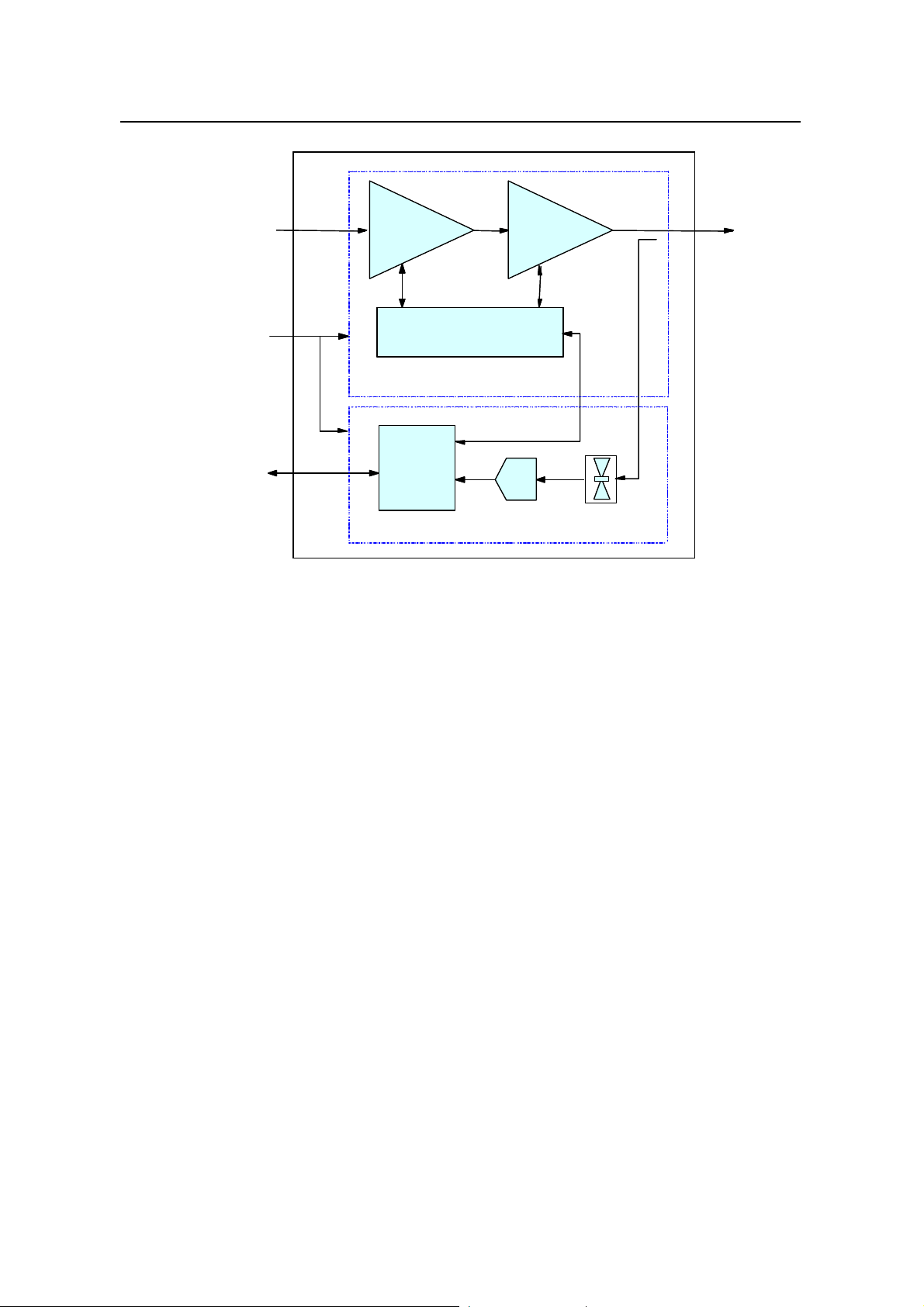
2.3 MPAM
2.3.1 Structure and Principle
Micro-bts Power Amplifier Module (MPAM) consists of Micro-bts Power Amplifier Unit
(MPAU) and Micro-bts Monitor & Control Board (MMCB).
The structure is shown in Figure 2-4.
2-6
User Manual
iSiteC ODU3601C CDMA Soft Base Station
MTRM
MTRM
RF input
RF input
MAPM
MAPM
MTRM
MTRM
+27V
+27V
RS-485
RS-485
Linear power
Linear power
amplifier
amplifier
MCU
MCU
Alarm circuit
Alarm circuit
Linear power
Linear power
MPAU
MPAU
A/D
A/D
MMCB
MMCB
amplifier
amplifier
System Description
Chapter 2 Hardware Architecture
Antenna
Antenna
Transmit power
Transmit power
detection
detection
Figure 2-4 Structure of MPAM module
I. MPAU
MPAU consists of two parts: linear power amplifier and alarm circuit.
The power amplifier amplifies the RF signals from MTRM. The amplified RF signals
are then sent to MFEM through the backplane.
The alarm circuit monitors the status of power amplifier and generates
over-temperature alarm, over-excited alarm and gain decrease alarm signals when
conditions satisfied. The alarm signals will be sent to MMCB, where they will be
processed and reported to MTRM.
The output power of MPAU can be adjusted by controlling the RF output signal of
MTRM.
II. MMCB
MMCB monitors the operation status of MPAU on the real-time basis, reports the
detected alarm, measures the transmit power of MPAU, and accomplishes
closed-loop power control for the front end RF channel to ensure a constant gain for
the whole analog channel. It can also power off the amplifier as instructed.
2-7

User Manual
iSiteC ODU3601C CDMA Soft Base Station
2.3.2 External Interface
MPAM provides the following external interfaces:
l RF interface to MTRM
MPAM is connected with MTRM through RF cable and receives RF output signals
from MTRM.
l RF interface to MFEM
MPAM is connected with MFEM through RF cable. It sends RF signals to MFEM,
which will be finally transmitted through the feeder system.
l Alarm interface
MPAM module is connected with MBKP through a connector. It sends alarm signals
through the RS485 serial bus on MBKP to MTRM for processing.
l Power supply interface
It supplies power to the module through MBKP.
System Description
Chapter 2 Hardware Architecture
2.3.3 Key Index
l Supported band: 450MHz band and 800MHz band
l Average output power: ¦ 40W (for 450MHz band)
¦ 28W (for 800MHz band)
l Power supply: +26V~+28V DC
l Power consumption: 230W
l Module size: L % W % T= 430mm % 250mm % 70mm (excluding heat tube
radiator)
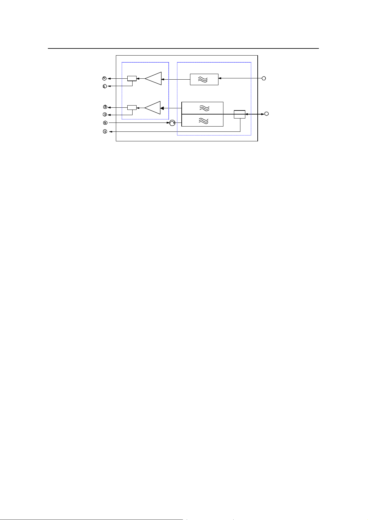
2.4 MFEM
2.4.1 Structure and Principle
Micro-bts Radio Frequency Front End Module (MFEM) consists of Micro-bts Divide
and Duplexer Receive Filter Unit (MRDU) and Micro-bts Low-Noise Amplifier (MLNA).
The functional structure is shown in Figure 2-5.
2-8
User Manual
iSiteC ODU3601C CDMA Soft Base Station
MLNA MRDU
RXD-OUT
RXD-Test
System Description
Chapter 2 Hardware Architecture
D
RXD-ANT
RXM-OUT
RXM-Test
TX
-IN
TX-Test
D
TX/RXM-ANT
Figure 2-5 Structure of MFEM
I. MRDU
MRDU contains a duplexer and a diversity receive filter.
l Duplexer
The duplexer is used to isolate transmit signals and receive signals, suppress
transmission spurious and reduce antenna quantity.
l Diversity receiving filter
Signals received from the diversity antenna are filtered first by the diversity receiving
filter in MRDU, then sent to MLNA for low-noise amplification.
II. MLNA unit
This unit contains 2 independent low-noise amplifiers and a MLNA status detection
unit.
l Low-noise amplifier
It performs low-noise amplification for main and diversity signals.
l MLNA status detection unit
The status monitoring circuit monitors the working voltage and current of MLNA, and
triggers an alarm when fault is detected.
2.4.2 External Interface
MFEM is connected with the feeder and other modules through RF cables. It provides
the following external interfaces:
l Interface to MPAM
On the transmit channel, MFEM receives RF signals amplified by MPAM, sends them
through the duplexer of MRDU to the antenna system for transmission.
l Interface to MTRM
2-9
User Manual
iSiteC ODU3601C CDMA Soft Base Station
On the receive channel, MFEM receives main/diversity RF signals from the antenna
system, and after low-noise amplification by MLNA, sends them to MTRM for
processing.
l Interface to the antenna system
l RF signal monitoring port
On the RF signal monitoring ports, the transmit signal is coupled and output by
MRDU, while the main/diversity receive signal is coupled and output by MLNA.
l Power supply interface
It supplies power to the module through MBKP.
2.4.3 Key Index
l Supported band: 450MHz band and 800MHz band
l Power supply: 20V~32V DC
l Power consumption: 11W
l Dimensions: L % W % T = 430mm % 250mm % 60mm
System Description
Chapter 2 Hardware Architecture
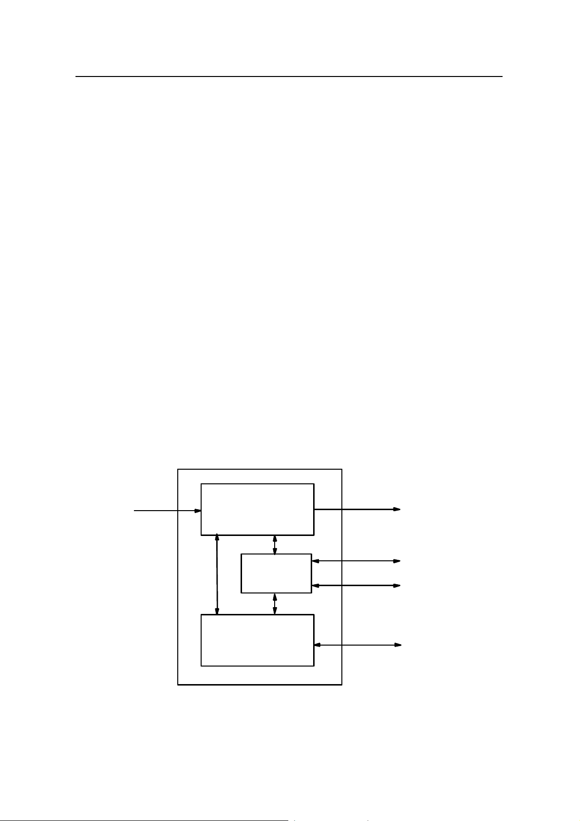
2.5 MAPM
2.5.1 Structure and Principle
The functional structure of MAPM is shown in Figure 2-6. MAPM consists of AC/DC
converter, power monitor & control unit, and battery management unit.
~220VAC
~220VAC
AC/DC power converter
AC/DC power converter
Battery management
Battery management
Power monitor &
Power monitor &
control unit
control unit
unit
unit
+27VDC
+27VDC
RS485
RS485
4 dry nodes
4 dry nodes
Battery interface
Battery interface
Figure 2-6 Structure of MAPM module
2-10

User Manual
iSiteC ODU3601C CDMA Soft Base Station
The AC/DC conversion unit converts Ã220V AC power (mains) into +27V DC power.
The power monitor & control unit performs status detection and alarm reporting.
The battery management unit performs energy charging and discharging for batteries.
2.5.2 External Interface
The external interfaces of MAPM are shown in Figure 2-6.
l AC input interface
Local mains are input through this interface.
l DC output interface
This interface is connected with the MBKP through which it supplies 27V DC power to
other modules.
l Battery interface
The external batteries can be connected with the MAPM through this interface so as
to supply power to the ODU3601C in the case of AC power failure.
System Description
Chapter 2 Hardware Architecture
l Alarm interface
MPAM is connected with MBKP through a connector. It sends alarm signals through
the RS485 serial bus on MBKP to MTRM for processing.
l Dry nodes
One of the four dry nodes is used to detect failure alarms of the AC lightning arrester,
while the other three are used to monitor the Uninterrupted Power Supply (UPS).
2.5.3 Key Index
l Phases of AC input: Single phase
l Rated voltage of AC input: 220V AC
l Fluctuation range of AC input voltage: 150~300V AC
l Overvoltage protection point of AC input: 310V AC
l Undervoltage protection point of AC input: 140V AC
l Dimensions: L % W % T = 430mm % 250mm % 90mm
2.6 MBKP
The backplane ODU3601C is the same as that of BTS3601C. The only difference is
that the slot 1 is not configured (with MBPM) when used for ODU3601C.
ODU3601C consists of four modules: MAPM, MTRM, MFEM, and MPAM. MBKP is
used to connect these four modules.
2-11
User Manual
iSiteC ODU3601C CDMA Soft Base Station
The power supply module supplies +27V DC power to other functional modules
through the MBKP.
The alarm signals of MPAM and MAPM are sent to MTRM through the RS485 bus on
MBKP. MTRM then transmits the signals through the optical fiber to the upper-level
BTS. The OMU of upper-level BTS processes these signals and sends them through
OML to BSC.
2.7 Antenna and Feeder Subsystem
The clock synchronization signal of ODU3601C is provided by the upper -level BTS
through the optical fiber. So the antenna and feeder system of ODU3601C only has
RF antenna and has no dual-satellite synchronization antenna.
The antenna and feeder subsystem transmits the modulated RF signals and receives
the signals from MS.
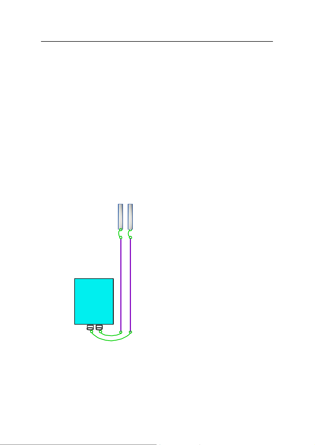
RF antenna & feeder is composed of the antenna, jumper from antenna to feeder,
feeder, and the jumper from feeder to cabinet-top, as shown in Figure 2-7.
System Description
Chapter 2 Hardware Architecture
RF antenna
RF antenna
Jumper
Jumper
Feeder
Feeder
ODU3601C
ODU3601C
Jumper
Jumper
Figure 2-7 Structure of RF antenna & feeder
2-12

User Manual
iSiteC ODU3601C CDMA Soft Base Station
&
Note:
If the distance from the antenna to the ODU3601C cabinet is within 15 meters, jumpers can be used
directly to connect the antenna and the cabinet. Detailed installation procedures are described in the
Installation Manual.
I. Antenna
Antenna is the end point of transmitting and start point of receiving. Antenna type,
gain, coverage pattern and front-to-rear ratio may affect the system performance. The
network designer should choose antenna properly based on the subscriber number
and system coverage.
1) Antenna gain
Antenna gain is the capability of the antenna to radiate the input power in specific
directions. Normally, the higher gain, the larger coverage. But there may be blind area
in the vicinity.
System Description
Chapter 2 Hardware Architecture
2) Antenna pattern
Antenna pattern describes the radiation intensity of the antenna in all directions. In
the field of telecommunication, it usually means a horizontal pattern. BTS antenna is
available in two types: omni antenna and directional antenna. The directional antenna
includes the following types: 120â, 90â , 65â and 33â.
3) Polarization
Polarization is used to describe the direction of the electrical field. The mobile
communication system often uses uni-polarization antennas. Bi-polarization antennae,
with the two polarization directions perpendicular to each other, have been used
recently to reduce the quantity of antennae.
4) Diversity technology
Electrical wave propagation in urban area has the following features:
l Field intensity value changes slowly with places and times. It changes in the rule
of logarithmic normal distribution, which is called slow attenuation.
l Field intensity transient value attenuates selectively due to multi-path
transmission. The attenuation rules falls in Rayleigh distribution, which is called
fast attenuation.
Either fast attenuation or slow attenuation impairs the quality of communication or
even interrupts the call. Diversity technology is one of the most effective technologies
to tackle the problem. Diversity receiving and combining tec hnology can be used to
minimize the attenuation when there is little correlation between the two attenuated
signals.
2-13

User Manual
iSiteC ODU3601C CDMA Soft Base Station
There are two types of diversity technologies: polarized diversity and space diversity.
In the present mobile communication system, horizontal space diversity and polarized
diversity are both supported. Theoretical conclusion shows that space diversity is
effective when the distance between two antennae is over 10 wavelengths.
Polarized diversity facilitates antenna installation and saves space, therefore it is
used more and more extensively.
5) Antenna isolation
The receiving/transmitting antenna must be installed with sufficient isolation to
minimize the effect on the receiver. The isolation space is subject to the out-band
noise of the transmitter and the sensitivity of the receiver.
II. Feeder
Normally, the standard 7/8 inch or 5/4 inch feeders are used to connect the outdoor
antenna and indoor cabinet. In the site installation, 7/16 DIN connectors should be
prepared based on the actual length of feeders.
System Description
Chapter 2 Hardware Architecture
Three grounding cable clips for lightning protection should be applied at the tower top
(or building roof), feeder middle, and the wall hole through which feeder is led indoor.
If the feeder is excessively long, additional cable clips are needed.
Since 7/8 inch feeder should not be bent, the tower top (or building roof) antenna and
the feeder, indoor cabinet and the feeder should be connected via jumpers. The
jumpers provided by Huawei are 1/2 inch, 3.5m long, and with 7/16DIN connectors.
At the 450MHz band, the loss is about 2.65dB every 100m for 7/8 inch feeder, and
about 1.87dB every 100m for 5/4 inch feeder.
At the 800MHz band, the loss is about 3.9dB every 100m for 7/8 inch feeder, and
about 2.8dB every 100m for 5/4 inch feeder.
2-14
 Loading...