

Huawei OceanStor 2000 V3, OceanStor 6000 V3, OceanStor 5500 V3, OceanStor 18000 V3, OceanStor 5600 V3 Features Manual
...Page 1

OceanStor V3 Series
V300R006
HyperMetro Feature Guide for File
Issue 05
Date 2018-01-30
HUAWEI TECHNOLOGIES CO., LTD.
Page 2

Copyright © Huawei Technologies Co., Ltd. 2018. All rights reserved.
No part of this document may be reproduced or transmitted in any form or by any means without prior written
consent of Huawei Technologies Co., Ltd.
Trademarks and Permissions
and other Huawei trademarks are trademarks of Huawei Technologies Co., Ltd.
All other trademarks and trade names mentioned in this document are the property of their respective
holders.
Notice
The purchased products, services and features are stipulated by the contract made between Huawei and the
customer. All or part of the products, services and features described in this document may not be within the
purchase scope or the usage scope. Unless otherwise specified in the contract, all statements, information,
and recommendations in this document are provided "AS IS" without warranties, guarantees or
representations of any kind, either express or implied.
The information in this document is subject to change without notice. Every effort has been made in the
preparation of this document to ensure accuracy of the contents, but all statements, information, and
recommendations in this document do not constitute a warranty of any kind, express or implied.
Huawei Technologies Co., Ltd.
Address: Huawei Industrial Base
Bantian, Longgang
Shenzhen 518129
People's Republic of China
Website: http://e.huawei.com
Issue 05 (2018-01-30) Huawei Proprietary and Confidential
Copyright © Huawei Technologies Co., Ltd.
i
Page 3
DANGER
WARNING
OceanStor V3 Series
HyperMetro Feature Guide for File
Purpose
This document describes the working principle and application scenarios of the HyperMetro
feature. It also explains how to configure and manage the feature.
The following table lists the product models applicable to this document.
About This Document
About This Document
Product Series
OceanStor 2000 V3 series OceanStor 2600 V3
OceanStor 5000 V3 series OceanStor 5300 V3, 5500 V3, 5600 V3, and
OceanStor 6000 V3 series OceanStor 6800 V3
OceanStor 18000 V3 series OceanStor 18500 V3 and 18800 V3
Intended Audience
This document is intended for:
l Technical support engineers
l Maintenance engineers
Symbol Conventions
Product Model
5800 V3
The symbols that may be found in this document are defined as follows.
Symbol
Issue 05 (2018-01-30) Huawei Proprietary and Confidential
Copyright © Huawei Technologies Co., Ltd.
Description
Indicates an imminently hazardous situation which, if not
avoided, will result in death or serious injury.
Indicates a potentially hazardous situation which, if not
avoided, could result in death or serious injury.
ii
Page 4

NOTE
OceanStor V3 Series
HyperMetro Feature Guide for File
Symbol Description
About This Document
Indicates a potentially hazardous situation which, if not
avoided, may result in minor or moderate injury.
Indicates a potentially hazardous situation which, if not
avoided, could result in equipment damage, data loss,
performance deterioration, or unanticipated results.
NOTICE is used to address practices not related to
personal injury.
Calls attention to important information, best practices and
tips.
NOTE is used to address information not related to
personal injury, equipment damage, and environment
deterioration.
Change History
Changes between document issues are cumulative. The latest document issue contains all the
changes in earlier issues.
Issue 05 (2018-01-30)
This is the fifth official release.
Optimized descriptions about section Impact and Restrictions.
Added the following FAQ: How Can I Use OVA Templates to Quickly Deploy Virtual
Quorum Servers?
Issue 04 (2017-11-30)
This is the fourth official release.
Added the description about arbitration mechanism or configuration operations when
configuring two quorum servers.
Issue 03 (2017-08-30)
This is the third official release.
Synchronizes some software interface changes.
Issue 02 (2017-06-01)
This is the second official release.
Optimized descriptions about section Impact and Restrictions.
Synchronizes some software interface changes.
Issue 05 (2018-01-30) Huawei Proprietary and Confidential
Copyright © Huawei Technologies Co., Ltd.
iii
Page 5

OceanStor V3 Series
HyperMetro Feature Guide for File
Issue 01 (2017-11-30)
This issue is the first official release.
About This Document
Issue 05 (2018-01-30) Huawei Proprietary and Confidential
Copyright © Huawei Technologies Co., Ltd.
iv
Page 6

OceanStor V3 Series
HyperMetro Feature Guide for File Contents
Contents
About This Document.....................................................................................................................ii
1 Feature Description....................................................................................................................... 1
1.1 Overview........................................................................................................................................................................ 1
1.2 License Requirements and Compatible Products........................................................................................................... 2
1.3 Working Principle........................................................................................................................................................... 3
1.3.1 Basic Concepts............................................................................................................................................................ 3
1.3.2 HyperMetro Solution Overview.................................................................................................................................. 5
1.3.3 Arbitration Mechanism..............................................................................................................................................10
1.3.4 HyperMetro I/O Processing Mechanism................................................................................................................... 25
1.4 Impact and Restrictions................................................................................................................................................ 29
1.5 Application Scenarios...................................................................................................................................................30
2 Planning........................................................................................................................................ 34
2.1 Network Planning......................................................................................................................................................... 34
2.2 Data Planning............................................................................................................................................................... 34
3 Installation.................................................................................................................................... 36
3.1 Installation Process....................................................................................................................................................... 37
3.2 Preparations for Installation..........................................................................................................................................37
3.2.1 Preparing Tools, Meters, and Documentation........................................................................................................... 37
3.2.2 Quick checklist for the installation environment.......................................................................................................40
3.3 Device Installation........................................................................................................................................................45
3.4 Cable Connection......................................................................................................................................................... 48
3.5 Power-on.......................................................................................................................................................................53
3.6 Storage Array Initialization.......................................................................................................................................... 56
3.7 Arbitration Software Installation.................................................................................................................................. 56
4 Configuration............................................................................................................................... 59
4.1 Configuration Process...................................................................................................................................................59
4.2 Configuration Preparations...........................................................................................................................................64
4.3 Configuring Switch.......................................................................................................................................................65
4.4 Configure Quorum Server Software.............................................................................................................................65
4.4.1 Configuring the Arbitration Software (SUSE).......................................................................................................... 65
4.4.2 Configuring the Arbitration Software (Red Hat/Red Flag/NeoKylin/CentOS)........................................................ 70
4.4.3 Configuring the Arbitration Software (Ubuntu)........................................................................................................76
Issue 05 (2018-01-30) Huawei Proprietary and Confidential
Copyright © Huawei Technologies Co., Ltd.
v
Page 7

OceanStor V3 Series
HyperMetro Feature Guide for File Contents
4.5 Configuring Basic Storage Services............................................................................................................................. 81
4.5.1 Creating a Disk Domain............................................................................................................................................ 81
4.5.2 Creating a Storage Pool............................................................................................................................................. 85
4.5.3 Creating a vStore....................................................................................................................................................... 93
4.5.4 Creating a File System...............................................................................................................................................93
4.5.5 Creating a Logical Port............................................................................................................................................110
4.5.6 Sharing a File System.............................................................................................................................................. 114
4.6 Creating NAS HyperMetro.........................................................................................................................................114
4.6.1 Checking the License File........................................................................................................................................114
4.6.2 Adding a Remote Device.........................................................................................................................................115
4.6.3 Creating a Quorum Server....................................................................................................................................... 118
4.6.4 Creating a HyperMetro Domain.............................................................................................................................. 121
4.6.5 Creating a HyperMetro vStore Pair......................................................................................................................... 122
4.6.6 Creating a NAS HyperMetro Pair........................................................................................................................... 123
4.6.7 (Optional) Creating a Quota Tree............................................................................................................................126
4.6.8 (Optional) Creating a Quota.................................................................................................................................... 128
4.6.9 (Optional) Creating a Snapshot............................................................................................................................... 131
4.6.9.1 Manually Creating a Snapshot..............................................................................................................................131
4.6.9.2 Creating a Periodic Snapshot................................................................................................................................133
4.7 Verifying the Configuration........................................................................................................................................134
5 Management............................................................................................................................... 135
5.1 Managing HyperMetro in the System View...............................................................................................................135
5.1.1 Managing a HyperMetro vStore Pair.......................................................................................................................135
5.1.1.1 Viewing HyperMetro vStore Pair Information.....................................................................................................135
5.1.1.2 Checking HyperMetro vStore Pair Information................................................................................................... 138
5.1.1.3 Deleting a HyperMetro vStore Pair...................................................................................................................... 139
5.1.1.4 Primary/Secondary Switchover............................................................................................................................ 140
5.1.1.5 Forcible Start........................................................................................................................................................ 141
5.1.1.6 Modifying the Owning Tenant of an Existing File System.................................................................................. 142
5.1.2 Managing HyperMetro Domains.............................................................................................................................143
5.1.2.1 Viewing HyperMetro Domain Information..........................................................................................................143
5.1.2.2 Modifying a HyperMetro Domain........................................................................................................................143
5.1.2.3 Deleting a HyperMetro Domain........................................................................................................................... 144
5.1.3 Managing a HyperMetro Pair.................................................................................................................................. 145
5.1.3.1 Viewing HyperMetro Pair Information................................................................................................................ 145
5.1.3.2 Modifying HyperMetro Pair Properties................................................................................................................150
5.1.3.3 Synchronizing a HyperMetro Pair........................................................................................................................152
5.1.3.4 Suspending a HyperMetro Pair.............................................................................................................................153
5.1.3.5 Deleting a HyperMetro Pair................................................................................................................................. 153
5.1.4 Managing Quorum Servers......................................................................................................................................154
5.1.4.1 Viewing Quorum Server Information...................................................................................................................154
5.1.4.2 Modifying Quorum Server Information............................................................................................................... 155
Issue 05 (2018-01-30) Huawei Proprietary and Confidential
Copyright © Huawei Technologies Co., Ltd.
vi
Page 8

OceanStor V3 Series
HyperMetro Feature Guide for File Contents
5.1.4.3 Adding a Link.......................................................................................................................................................156
5.1.4.4 Removing a Link.................................................................................................................................................. 156
5.1.4.5 Removing a Quorum Server................................................................................................................................. 157
5.1.4.6 Uninstalling the Arbitration Software.................................................................................................................. 157
5.1.5 Importing Certificates..............................................................................................................................................158
5.2 Managing HyperMetro in the Tenant View................................................................................................................ 161
5.2.1 Viewing HyperMetro Pair Information................................................................................................................... 161
5.2.2 Modifying HyperMetro Pair Properties...................................................................................................................167
5.2.3 Synchronizing a HyperMetro Pair...........................................................................................................................169
5.2.4 Suspending a HyperMetro Pair................................................................................................................................170
5.2.5 Deleting a HyperMetro Pair.................................................................................................................................... 170
6 FAQs.............................................................................................................................................172
6.1 What Can I Do If a Quorum Link Fails to Be Added Because the HyperMetro Arbitration Certificate Becomes
Invalid or the System Time Becomes Abnormal?............................................................................................................172
6.2 Active and Standby IP Ports Are Configured on the Quorum Server. After the Port in Use Is Down, the Quorum
Server Goes Offline. Why?...............................................................................................................................................174
6.3 How Do I Power Off Active-Active Storage Systems and Resume the HyperMetro Service?................................. 175
6.4 When Both the HyperMetro and Remote Backup Services Are Created, the Excessively Low Link Bandwidth
Between Storage Systems Causes the Remote Backup Service to Fail............................................................................176
6.5 What Can I Do If the Remote Connection Fails to Be Created with the TOE Interface Module.............................. 177
6.6 How Can I Use OVA Templates to Quickly Deploy Virtual Quorum Servers?......................................................... 177
7 Troubleshooting........................................................................................................................ 182
7.1 A Quorum Link Fails to Be Added After the Quorum Server Is Replaced................................................................182
A How to Obtain Help.................................................................................................................184
A.1 Preparations for Contacting Huawei..........................................................................................................................184
A.1.1 Collecting Troubleshooting Information................................................................................................................ 184
A.1.2 Making Debugging Preparations............................................................................................................................ 185
A.2 How to Use the Document.........................................................................................................................................185
A.3 How to Obtain Help from Website............................................................................................................................ 185
A.4 Ways to Contact Huawei............................................................................................................................................185
B Glossary...................................................................................................................................... 186
C Acronyms and Abbreviations................................................................................................ 187
Issue 05 (2018-01-30) Huawei Proprietary and Confidential
Copyright © Huawei Technologies Co., Ltd.
vii
Page 9

OceanStor V3 Series
HyperMetro Feature Guide for File
About This Chapter
HyperMetro provides you with disaster recovery functions and enables you to synchronize
and replicate data between storage arrays, monitor service operating status, and perform
failovers. You can switch over services and implement service load sharing while your storage
array is running.
1 Feature Description
1 Feature Description
1.1 Overview
This section describes the background, definition, and benefits of HyperMetro.
1.2 License Requirements and Compatible Products
This section describes the availability of HyperMetro in terms of the license requirement and
applicable version.
1.3 Working Principle
This section introduces the basic concepts, I/O processing mechanism, and arbitration
mechanism of HyperMetro and describes how to use HyperMetro for service switchover and
recovery.
1.4 Impact and Restrictions
This section describes the impact and restrictions of HyperMetro feature.
1.5 Application Scenarios
This section introduces the application scenarios of HyperMetro.
1.1 Overview
This section describes the background, definition, and benefits of HyperMetro.
Background
With the rapid development of the information technology (IT), storage systems are becoming
ever important for critical services in a variety of industries. Service interruptions in storage
systems may lead to severe economic loss, damaged brand images, or critical data loss,
especially in the fields of communications, finance, medical care, e-commerce, logistics, and
governments. Therefore, service continuity is critical to the construction of storage systems.
Traditionally, one production center and one disaster recovery center are constructed, and the
Issue 05 (2018-01-30) Huawei Proprietary and Confidential
Copyright © Huawei Technologies Co., Ltd.
1
Page 10

OceanStor V3 Series
HyperMetro Feature Guide for File
disaster recovery center is active only when the production center is down. This disaster
recovery system is facing the following challenges:
l If the production center encounters power supply failures, fires, floods, or earthquakes,
you must switch services from the production center to the disaster recovery center.
Services are interrupted for a long time and service continuity cannot be ensured.
l The disaster recovery center remains idle for most of the time, lowering resource
utilization.
Definition
HyperMetro enables storage systems in two different data centers to process services
simultaneously, establishing a mutual backup relationship. If the storage system in one data
center malfunctions, the storage system in the other data center automatically takes over
services without data loss or service interruption.
Benefits
Table 1-1 lists the benefits of HyperMetro.
1 Feature Description
Table 1-1 Benefits of HyperMetro
Benefit
Robust reliability If the storage system in one data center
High compatibility By integrating SmartVirtualization, HyperMetro
Description
malfunctions, the storage system in the other data
center automatically takes over services without
data loss or service interruption.
enables full utilization of storage resources,
minimizes upgrade costs, and is fully compatible
with storage systems from most vendors,
including EMC, IBM, HDS, HP, and SUN.
1.2 License Requirements and Compatible Products
This section describes the availability of HyperMetro in terms of the license requirement and
applicable version.
License Requirement
HyperMetro is a value-added feature that requires a software license for use on both local and
remote storage systems.
Applicable products
Product Series
OceanStor 2000 V3 series OceanStor 2600 V3 V300R006
Issue 05 (2018-01-30) Huawei Proprietary and Confidential
Copyright © Huawei Technologies Co., Ltd.
Product Model Version
2
Page 11

OceanStor V3 Series
HyperMetro Feature Guide for File
Product Series Product Model Version
1 Feature Description
OceanStor 5000 V3 series OceanStor 5300 V3, 5500
OceanStor 6000 V3 series OceanStor 6800 V3 V300R006
OceanStor 18000 V3 series OceanStor 18500 V3 and
Applicable Software Versions
Software
OceanStor
UltraPath
OceanStor
QuorumServer
NOTE
Log in to http://support.huawei.com/enterprise/ and you can register for an account on the website. After
you log in with the applied user name and password. Choose Support > Enterprise Storage and click the
corresponding product model to access the product document page.
l Input Version Mapping in the search box and press Enter to obtain the product document.
l Enter the software name to obtain the software.
V300R006
V3, 5600 V3, and 5800 V3
V300R006
18800 V3
Version
When configuring HyperMetro services, use OceanStor UltraPath
V100R008C50SPC500 or later.
When configuring HyperMetro services, use OceanStor
QuorumServer V300R006 or later.
1.3 Working Principle
This section introduces the basic concepts, I/O processing mechanism, and arbitration
mechanism of HyperMetro and describes how to use HyperMetro for service switchover and
recovery.
1.3.1 Basic Concepts
This section describes basic concepts of HyperMetro, including tenant, HyperMetro tenant
pair, local file system, remote file system, synchronization, pause, data status, and others.
Tenant
Multiple virtual storage systems can be created in one physical storage system and multiple
tenants can share the same storage hardware resources without affecting data security and
privacy of each other. Tenants enable flexible, easy-to-manage, and cost-effective shared
storage in a multi-protocol unified storage architecture.
HyperMetro Tenant Pair
A HyperMetro tenant pair indicates a HyperMetro relationship between tenants of the local
and remote storage arrays. The HyperMetro arbitration is implemented in the unit of a
Issue 05 (2018-01-30) Huawei Proprietary and Confidential
Copyright © Huawei Technologies Co., Ltd.
3
Page 12

OceanStor V3 Series
HyperMetro Feature Guide for File
HyperMetro tenant pair. If a fault occurs in a HyperMetro tenant pair, ensure the arbitration
results of all file systems in the tenants of the HyperMetro tenant pair are the same and the
environments in which the file systems are running are consistent between the tenants.
Logical Port
Logical ports are created based on physical Ethernet ports, bond ports, or VLANs and used
for file service operation.
Local File System and Remote File System
In a HyperMetro pair, the file system on the local storage array is called local file system and
the file system on the remote storage array is called remote file system.
Dual-Write
Dual-write enables the synchronization of application host I/O requests with both local and
remote file systems.
1 Feature Description
DCL
DCLs record changes in the data of storage arrays.
Quorum Server
For NAS HyperMetro, if the heartbeats between two storage arrays are interrupted, the
quorum server decides which storage array continues providing services, thereby greatly
improving host service continuity.
HyperMetro Domain
A HyperMetro domain consists of the local storage array, remote storage array, and the
quorum server. Application servers can access data across data centers using a HyperMetro
domain. Before configuring a HyperMetro pair, you must configure the HyperMetro domain
first. Each HyperMetro pair must be created in the HyperMetro domain.
NAS HyperMetro Pair
A NAS HyperMetro pair indicates a HyperMetro relationship between the local and remote
file systems. After HyperMetro is configured, a local file system on the local storage array
and a remote file system on the remote storage array form a NAS HyperMetro pair. By
viewing the state of a HyperMetro pair, you can determine whether you need to perform
synchronization and suspension operations. After performing an operation, you can view the
state of the HyperMetro pair to determine whether the operation succeeded.
Synchronization
Synchronization refers to the synchronization of differential data between a local file system
and a remote file system.
Issue 05 (2018-01-30) Huawei Proprietary and Confidential
Copyright © Huawei Technologies Co., Ltd.
4
Page 13

OceanStor V3 Series
HyperMetro Feature Guide for File
Pause
Pause is a state indicating the suspension of a HyperMetro pair formed by a local file system
and a remote file system.
Force Start
To ensure data consistency when the local and remote storage systems malfunction
simultaneously, HyperMetro stops hosts from accessing both. To quickly restore services, you
can forcibly start the local or remote storage system.
Priority Switchover
Priority switchover indicates that the storage array at the preferred site takes precedence to
provide services for hosts. If the storage array at the preferred site needs to be repaired or
maintained, a priority switchover is performed to enable the storage array at the non-preferred
site to provide services for hosts.
1.3.2 HyperMetro Solution Overview
1 Feature Description
This section describes the HyperMetro solution network and provides a logical HyperMetro
network topology to show the mapping relationship and data flows between host applications
and storage arrays.
If the storage array in one data center malfunctions, host services are switched to the storage
array in the other data center. If the link between two storage arrays in two data centers is
down, only one storage array can be accessed by hosts. The quorum server determines which
storage array continues providing services.
Network Overview
Fibre Channel networking is used as an example to explain HyperMetro solution network
topology. For details, see Figure 1-1.
Issue 05 (2018-01-30) Huawei Proprietary and Confidential
Copyright © Huawei Technologies Co., Ltd.
5
Page 14

OceanStor V3 Series
HyperMetro Feature Guide for File
Figure 1-1 HyperMetro solution network topology
1 Feature Description
Ethernet switch
Ethernet switch
Fibre Channel switch
Local storage array
Data center A
Fibre Channel
switch
Ethernet switch
Host cluster
IP
FC
IP
Quorum site
Host cluster
Fibre Channel
Quorum server
Ethernet switch
Ethernet switch
Fibre Channel switch
switch
Remote storage array
Data center B
Ethernet switch
Host-to-storage network
HyperMetro replication
network
Same-city cross-DC
network
Quorum network
To ensure reliability of storage arrays, establish redundant links among the network between
hosts and storage arrays, HyperMetro replication network, same-city network between data
centers, and quorum network.
Table 1-2 Network overview
Network
Network of hosts and
storage systems
All hosts in the two data
centers can form a
cluster and host
networks can
interconnect across data
centers.
Description
Network
type
Networking
mode
Supports GE and 10GE networks.
l A fully interconnected network is used
between hosts and storage systems, that is,
each service host is physically and logically
connected to two HyperMetro storage
arrays.
l Dual-switch networking is required.
l The HyperMetro replication network,
storage-to-host network, and quorum
network need to be physically isolated and
common ports are not recommended on
storage devices.
Issue 05 (2018-01-30) Huawei Proprietary and Confidential
Copyright © Huawei Technologies Co., Ltd.
6
Page 15

OceanStor V3 Series
HyperMetro Feature Guide for File
Network Description
1 Feature Description
HyperMetro replication
network
This is the heartbeat
network between the
storage systems in the
two data centers. It
enables the storage
systems to provide
services for hosts
concurrently and
ensures data
synchronization
between them.
NOTE
The storage system sets
link priorities for different
types of information for
transferring data. The link
priority of heartbeat
information is higher than
that of data
synchronization
information.
Network
type
l Supports 10GE, 8 Gbit/s Fibre Channel, and
16 Gbit/s Fibre Channel networks.
NOTE
When using the 10GE network, you are advised
to use the L2 network.
l Network quality and bandwidth
requirements for deploying the network:
– Bandwidth: ≥ peak service bandwidth
– Latency: The maximum supported RTT
is 10 ms (distance < 300 km)
NOTE
In practice, the latency is determined by the
requirements of the application layer. The
active/active solution must meet the
minimum latency requirement. The RTT of
the VMware vSphere applications is less than
10 ms (with a distance of less than 300 km).
The RTT of the SAP HANA applications is
less than 1 ms (with a distance of less than
100 km).
– No jitter and packet loss
– BER: ≤ 10
-12
l The HyperMetro replication network,
storage-to-host network, and quorum
network need to be physically isolated and
common ports are not recommended on
storage devices.
Same-city network
between data centers
The storage systems in
data centers A and B
provide the same
services for hosts. There
is a mutual backup
relationship between the
two storage systems. If
the storage system in
one data center
malfunctions, the
storage system in the
other data center
automatically takes over
services without data
loss or service
interruption.
Networking
mode
Network
type
Each controller of the HyperMetro array has at
least two links and at most four links for
redundancy.
The network uses bare fibers.
Issue 05 (2018-01-30) Huawei Proprietary and Confidential
Copyright © Huawei Technologies Co., Ltd.
7
Page 16

OceanStor V3 Series
HyperMetro Feature Guide for File
Network Description
1 Feature Description
Networking
mode
l For Fibre Channel networks:
– The two data centers can be directly
connected using bare fibers if their
distance is within 25 km. Ensure that the
storage and application layers each have
at least two pairs (four wires) of bare
fibers for heartbeat interconnection in the
cluster.
– If the data centers are greater than or
equal to 25 km apart, use dense
wavelength division multiplexing
(DWDM) devices to interconnect them.
l For IP networks:
– The two data centers can be directly
connected using bare fibers if their
distance is within 80 km. If core switches
are deployed, ensure that at least two
pairs (four wires) of bare fibers are
connected to the core switches for
HyperMetro mirroring at the storage
layer and heartbeat interconnection at the
application layer.
– If the data centers are greater than or
equal to 80 km apart, use DWDM
devices to interconnect them.
If IP networking is used for the application
layer, ensure that the Fiber Channel network
with at least two pairs (four wires) of optical
cables is set up for heartbeat interconnection in
the cluster.
Issue 05 (2018-01-30) Huawei Proprietary and Confidential
Copyright © Huawei Technologies Co., Ltd.
8
Page 17

OceanStor V3 Series
HyperMetro Feature Guide for File
Network Description
1 Feature Description
Quorum network
If communication
between the storage
systems in data centers
A and B is interrupted
or a storage system
malfunctions, the
quorum server
determines which
storage system is
accessible.
NOTE
A quorum server is
deployed on the quorum
network. If storage arrays
in the two data centers
encounter a device fault
or a link between the
storage arrays is down,
the quorum server
determines the access
status of data center A
and data center B
according to the
arbitration result.
Network
type
l Quorum links support GE and 10GE
networks as long as routes are reachable.
The Fibre Channel network is not supported.
l Quorum links support IPv4 and IPv6
addresses.
l For versions earlier than V300R006C10, the
arbitration link port cannot use a storage
device's management or maintenance
network port. For V300R006C10 and later
versions, the arbitration link port can use a
storage device's management network port,
but cannot use its maintenance network port.
l Network quality and bandwidth
requirements for deploying the network:
– Latency: RTT ≤ 50 ms
– Bandwidth: ≥ 10 Mbit/s
l The HyperMetro replication network,
storage-to-host network, and quorum
network need to be physically isolated and
common ports are not recommended on
storage devices.
Issue 05 (2018-01-30) Huawei Proprietary and Confidential
Copyright © Huawei Technologies Co., Ltd.
9
Page 18

OceanStor V3 Series
HyperMetro Feature Guide for File
Network Description
1 Feature Description
Networking
mode
l Quorum servers are supported but quorum
disks are not.
l You are advised to deploy the quorum server
at a third-place site. If there is no third-place
site, you are advised to deploy the quorum
server at the preferred site. In this case, the
quorum server and related devices should
have uninterruptible power supply (UPS)
protection.
l A dual-switch network is recommended. A
GE/10GE port on each controller of a
storage array is connected to the third-place
quorum server and the service network ports
on the quorum server are connected to two
storage arrays, ensuring that the quorum
server is connected to all controllers of each
storage array.
If a controller houses only one quorum port,
connect controller A and controller C to
switch 1 on IP network segment 1 and
connect controller B and controller D to
switch 2 on IP network segment 2.
If each controller has two quorum ports,
connect the first quorum port on each
controllers to switch 1 and configure IP
network segment 1. In addition, connect the
second quorum port on each controller to
switch 2 and configure IP network segment
2.
l Huawei Enterprise Cloud (HEC) can be used
as a quorum server.
When the HEC is used as the quorum server,
apply for a VM (including the CPU,
memory, disk, and OS). The VM
specifications are the same as those of the
quorum server. Apply for 2 Mbit/s exclusive
bandwidth and one elastic IP address for
each disk array.
1.3.3 Arbitration Mechanism
If the link between the two data centers breaks down, they can no longer be synchronized and
only one will continue providing services. HyperMetro supports two arbitration modes to
determine which data center continues providing services and ensure data consistency:
l Static priority mode is used when there is no quorum server available.
l Quorum server mode is used when quorum servers have been deployed.
Issue 05 (2018-01-30) Huawei Proprietary and Confidential
Copyright © Huawei Technologies Co., Ltd.
10
Page 19

OceanStor V3 Series
HyperMetro Feature Guide for File
NOTE
The quorum server mode is recommended. After a quorum server is deployed, the non-preferred site of
HyperMetro will automatically take over services once the preferred site becomes faulty, without causing
HyperMetro service interruption.
Static Priority Mode
The static priority mode applies to scenarios where no third-place quorum server is deployed.
In a HyperMetro vStore pair, you can set one data center as the preferred site and the other as
the non-preferred site. In the following example, data center A is used as a preferred site.
Table 1-3 describes the arbitration mechanism in static priority mode.
NOTE
You can set the Recovery Policy for HyperMetro pair failures by Modifying HyperMetro Pair Properties.
l Automatic: The system automatically synchronizes data for data recovery.
l Manual: You must manually synchronize data for data recovery.
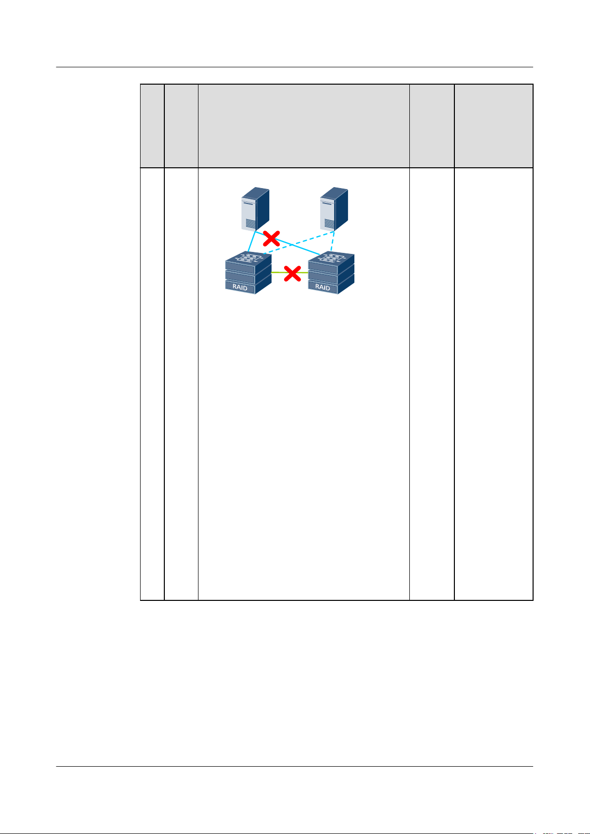
Table 1-3 Arbitration mechanism in static priority mode
1 Feature Description
Fault
N
Diagram
o.
1 The link
between
two storage
arrays
breaks
down.
2 The storage
array in
data center
B (nonpreferred
site)
malfunction
s.
3 The storage
array in
data center
A
(preferred
site)
malfunction
s.
Fault Type HyperMetr
o Pair
Running
Status
To be
synchronize
d
Data center A Data center B
To be
synchronize
d
Data center A Data center B
To be
synchronize
d
Data center A Data center B
Arbitration
Result
A continues
providing
services
while B
stops.
A continues
providing
services
while B
stops.
Both A and
B stop. You
must
forcibly start
B to resume
providing
services for
hosts.
Green cable: HyperMetro replication network
Issue 05 (2018-01-30) Huawei Proprietary and Confidential
Copyright © Huawei Technologies Co., Ltd.
11
Page 20

OceanStor V3 Series
HyperMetro Feature Guide for File
Quorum Server Mode
In quorum server mode, the heartbeat network determines whether the storage arrays are
working properly. If a malfunction occurs, each data center sends an arbitration request to the
quorum server, and only the winner continues providing services.
The quorum site supports two quorum servers for V300R006C10 and later versions. The two
quorum servers work in active/standby mode. Once the active quorum server is faulty, the
system automatically switches to the standby quorum server to execute the arbitration
function.
In a HyperMetro vStore pair, you can set one data center as the preferred site, which takes
precedence in arbitration, and the other as the non-preferred site. In the following example,
data center A is used as a preferred site. Table 1-4 and Table 1-5 describe the arbitration
mechanisms when one and two quorum servers are deployed, respectively.
NOTE
You can set the Recovery Policy for HyperMetro pair failures by Modifying HyperMetro Pair Properties.
l Automatic: The system automatically synchronizes data for data recovery.
l Manual: You must manually synchronize data for data recovery.
1 Feature Description
Table 1-4 Arbitration mechanism in single-quorum-server mode
Fault
N
Diagram
o.
1 The
Fault Type Hyper
Quorum server
quorum
server
breaks
down.
Data center A Data center B
Arbitration
Metro
Result
Pair
Runni
ng
Status
Normal A continues
providing
services while
B stops.
NOTE
HyperMetro
automatically
switches to
static priority
arbitration.
Issue 05 (2018-01-30) Huawei Proprietary and Confidential
Copyright © Huawei Technologies Co., Ltd.
12
Page 21

OceanStor V3 Series
HyperMetro Feature Guide for File
1 Feature Description
No.Fault
Diagram
2 The link
between the
quorum
server and
one or both
storage
arrays
breaks
down.
Fault Type Hyper
Metro
Pair
Runni
ng
Status
Normal A continues
1
Data center A Data center B
2
Quorum server
Quorum server
Arbitration
Result
providing
services while
B stops.
3 The storage
array in
data center
A
(preferred
site)
malfunctio
ns.
Data center A Data center B
3
Quorum server
Data center A Data center B
Quorum server
Data center A Data center B
To be
synchr
onized
B starts
providing
services while
A stops.
Issue 05 (2018-01-30) Huawei Proprietary and Confidential
Copyright © Huawei Technologies Co., Ltd.
13
Page 22

OceanStor V3 Series
HyperMetro Feature Guide for File
1 Feature Description
No.Fault
Diagram
4 The storage
array in
data center
B (nonpreferred
site)
malfunctio
ns.
5 The link
between
two storage
arrays
breaks
down.
Fault Type Hyper
Metro
Pair
Runni
ng
Status
Quorum server
To be
synchr
onized
Data center A Data center B
Quorum server
To be
synchr
onized
Arbitration
Result
A continues
providing
services while
B stops.
A continues
providing
services while
B stops.
6 One storage
array and
the quorum
server both
malfunctio
n.
Data center A Data center B
1
Data center A Data center B
2
Data center A Data center B
Quorum server
Quorum server
To be
synchr
onized
Both A and B
stop.
NOTE
You must
forcibly start
the working file
system to
resume
providing
services for
hosts.
Issue 05 (2018-01-30) Huawei Proprietary and Confidential
Copyright © Huawei Technologies Co., Ltd.
14
Page 23

OceanStor V3 Series
HyperMetro Feature Guide for File
1 Feature Description
No.Fault
Diagram
7 The link
between the
two storage
arrays and
the link
between the
storage
array in
data center
B and the
quorum
server both
break
down.
8 The link
between the
two storage
arrays and
the link
between the
storage
array in
data center
A and the
quorum
server both
break
down.
Fault Type Hyper
Metro
Pair
Runni
ng
Status
Quorum server
To be
synchr
onized
Data center A Data center B
Quorum server
To be
synchr
onized
Data center A Data center B
Arbitration
Result
A continues
providing
services while
B stops.
B starts
providing
services while
A stops.
Issue 05 (2018-01-30) Huawei Proprietary and Confidential
Copyright © Huawei Technologies Co., Ltd.
15
Page 24

OceanStor V3 Series
HyperMetro Feature Guide for File
1 Feature Description
No.Fault
Diagram
9 One storage
array
malfunctio
ns and the
link
between the
other
storage
array and
the quorum
server is
down.
Fault Type Hyper
Metro
Pair
Runni
ng
Status
To be
1
Quorum server
synchr
onized
Data center A Data center B
2
Quorum server
Arbitration
Result
Both A and B
stop.
NOTE
You must
forcibly start
the working file
system to
resume
providing
services for
hosts.
10 The
quorum
server
malfunctio
ns. Then
the link
between
two storage
arrays is
down.
11 The
quorum
server
malfunctio
ns. At the
same time,
the link
between
two storage
arrays is
down.
Data center A Data center B
Quorum server
Data center A Data center B
Quorum server
Data center A Data center B
To be
synchr
onized
To be
synchr
onized
A continues
providing
services while
B stops.
NOTE
HyperMetro
automatically
switches to
static priority
arbitration.
Both A and B
stop.
NOTE
You must
manually start
A to resume
providing
services for
hosts.
Issue 05 (2018-01-30) Huawei Proprietary and Confidential
Copyright © Huawei Technologies Co., Ltd.
16
Page 25

OceanStor V3 Series
HyperMetro Feature Guide for File
1 Feature Description
No.Fault
Fault Type Hyper
Diagram
Green cable: HyperMetro replication network
Blue cable: quorum network
Table 1-5 Arbitration mechanism in dual-quorum-server mode
N
o.
Faul
t
Fault Diagram Hyper
Typ
e
1 The
Quorum server (active)
Quorum server (standby)
quor
um
serve
r
break
s
down
.
Data center A Data cente B
Arbitration
Metro
Result
Pair
Runni
ng
Status
Arbitration
Metro
Result
Pair
Runni
ng
Status
Normal The standby
quorum server
takes over the
arbitration
services from
the active
quorum server.
A continues
providing
services while
B stops.
Issue 05 (2018-01-30) Huawei Proprietary and Confidential
Copyright © Huawei Technologies Co., Ltd.
17
Page 26

OceanStor V3 Series
HyperMetro Feature Guide for File
1 Feature Description
No.Faul
t
Typ
e
2 The
link
betw
een
the
activ
e
quor
um
serve
r and
one
or
both
stora
ge
array
s
break
s
down
.
Fault Diagram Hyper
Metro
Pair
Runni
ng
Status
1
Quorum server (active)
Data center A
2
Quorum server (active) Quorum server (standby)
Data center A
3
Quorum server (active)
Quorum server (standby)
Data cente B
Data cente B
Quorum server (standby)
Normal
Arbitration
Result
l In scenarios
1 and 2, the
active
quorum
server runs
properly. A
continues
providing
services
while B
stops.
l In scenario
3, the
standby
quorum
server takes
over the
arbitration
services
from the
active
quorum
server. A
continues
providing
services
while B
stops.
Data center A
Issue 05 (2018-01-30) Huawei Proprietary and Confidential
Copyright © Huawei Technologies Co., Ltd.
Data cente B
18
Page 27

OceanStor V3 Series
HyperMetro Feature Guide for File
1 Feature Description
No.Faul
t
Typ
e
3 The
stora
ge
array
in
data
cente
r A
(pref
erred
site)
malf
uncti
ons.
4 The
stora
ge
array
in
data
cente
r B
(nonprefe
rred
site)
malf
uncti
ons.
Fault Diagram Hyper
Metro
Pair
Runni
ng
Status
Quorum server (active)
Quorum server (standby)
To be
synchro
nized
Data center A Data cente B
Quorum server (active)
Quorum server (standby)
To be
synchro
nized
Data center A Data cente B
Arbitration
Result
The active
quorum server
runs properly.
B provides
services while
A stops.
The active
quorum server
runs properly.
A continues
providing
services while
B stops.
5 The
Quorum server (active)
Quorum server (standby)
link
betw
een
two
stora
ge
array
s
break
s
Data center A Data cente B
down
.
Issue 05 (2018-01-30) Huawei Proprietary and Confidential
Copyright © Huawei Technologies Co., Ltd.
To be
synchro
nized
The active
quorum server
runs properly.
A continues
providing
services while
B stops.
19
Page 28

OceanStor V3 Series
HyperMetro Feature Guide for File
1 Feature Description
No.Faul
t
Typ
e
6 One
stora
ge
array
and
the
activ
e
quor
um
serve
r
both
malf
uncti
on.
Fault Diagram Hyper
Metro
Pair
Runni
ng
Status
1
Quorum server (active)
Quorum server (standby)
To be
synchro
nized
Data center A Data cente B
2
Quorum server (active)
Data center A Data cente B
Quorum server (standby)
Arbitration
Result
l In scenario
1, the
standby
quorum
server takes
over the
arbitration
services
from the
active
quorum
server. B
provides
services
while A
stops.
l In scenario
2, the
standby
quorum
server takes
over the
arbitration
services
from the
active
quorum
server. A
continues
providing
services
while B
stops.
Issue 05 (2018-01-30) Huawei Proprietary and Confidential
Copyright © Huawei Technologies Co., Ltd.
20
Page 29
OceanStor V3 Series
HyperMetro Feature Guide for File
1 Feature Description
No.Faul
t
Typ
e
7 The
link
betw
een
the
two
stora
ge
array
s and
the
link
betw
een
the
stora
ge
array
in
data
cente
r B
and
the
activ
e
quor
um
serve
r
both
break
down
.
Fault Diagram Hyper
Metro
Pair
Runni
ng
Status
Quorum server (active)
Quorum server (standby)
To be
synchro
nized
Data center A Data cente B
Arbitration
Result
The active
quorum server
runs properly.
A continues
providing
services while
B stops.
Issue 05 (2018-01-30) Huawei Proprietary and Confidential
Copyright © Huawei Technologies Co., Ltd.
21
Page 30

OceanStor V3 Series
HyperMetro Feature Guide for File
1 Feature Description
No.Faul
t
Typ
e
8 The
link
betw
een
the
two
stora
ge
array
s and
the
link
betw
een
the
stora
ge
array
in
data
cente
r A
and
the
activ
e
quor
um
serve
r
both
break
down
.
Fault Diagram Hyper
Metro
Pair
Runni
ng
Status
Quorum server (active)
Quorum server (standby)
To be
synchro
nized
Data center A Data cente B
Arbitration
Result
The active
quorum server
runs properly.
B provides
services while
A stops.
Issue 05 (2018-01-30) Huawei Proprietary and Confidential
Copyright © Huawei Technologies Co., Ltd.
22
Page 31

OceanStor V3 Series
HyperMetro Feature Guide for File
1 Feature Description
No.Faul
t
Typ
e
9 One
stora
ge
array
malf
uncti
ons
and
the
link
betw
een
the
other
stora
ge
array
and
the
activ
e
quor
um
serve
r is
down
.
Fault Diagram Hyper
Metro
Pair
Runni
ng
Status
1
Quorum server (active)
Quorum server (standby)
To be
synchro
nized
Data center A Data cente B
2
Quorum server (active) Quorum server (standby)
Data center A Data cente B
Arbitration
Result
l In scenario
1, the
standby
quorum
server takes
over the
arbitration
services
from the
active
quorum
server. B
provides
services
while A
stops.
l In scenario
2, the
standby
quorum
server takes
over the
arbitration
services
from the
active
quorum
server. A
continues
providing
services
while B
stops.
Issue 05 (2018-01-30) Huawei Proprietary and Confidential
Copyright © Huawei Technologies Co., Ltd.
23
Page 32

OceanStor V3 Series
HyperMetro Feature Guide for File
1 Feature Description
No.Faul
t
Typ
e
10 The
activ
e
quor
um
serve
r
malf
uncti
ons.
Then
the
link
betw
een
two
stora
ge
array
s is
down
.
Fault Diagram Hyper
Metro
Pair
Runni
ng
Status
Quorum server (active)
Quorum server (standby)
To be
synchro
nized
Data center A Data cente B
Arbitration
Result
The standby
quorum server
takes over the
arbitration
services from
the active
quorum server.
A continues
providing
services while
B stops.
Issue 05 (2018-01-30) Huawei Proprietary and Confidential
Copyright © Huawei Technologies Co., Ltd.
24
Page 33

OceanStor V3 Series
HyperMetro Feature Guide for File
1 Feature Description
No.Faul
t
Typ
e
11 The
activ
e
quor
um
serve
r
malf
uncti
ons.
At
the
same
time,
the
link
betw
een
two
stora
ge
array
s is
down
.
Fault Diagram Hyper
Metro
Pair
Runni
ng
Status
Quorum server (active)
Quorum server (standby)
To be
synchro
nized
Data center A Data cente B
Arbitration
Result
The standby
quorum server
takes over the
arbitration
services from
the active
quorum server.
Both A and B
stop.
NOTE
You must
manually start
A to resume
providing
services for
hosts.
Green cable: HyperMetro replication network
Blue solid cable: quorum network between the active quorum server and data centers
Blue dotted cable: quorum network between the standby quorum server and data centers
1.3.4 HyperMetro I/O Processing Mechanism
HyperMetro uses the dual-write and DCL technologies to synchronize data changes between
two data centers, ensuring data consistency.
Basic Concepts
You are advised to know the key concepts of HyperMetro before reading the I/O processing
mechanism. For details, see 1.3.1 Basic Concepts.
Data HyperMetro Implementation
The core for implementing data HyperMetro of two storage arrays lies in the tenant-based
logical port mechanism and dual-write mechanism. Data changes can be synchronized using
Issue 05 (2018-01-30) Huawei Proprietary and Confidential
Copyright © Huawei Technologies Co., Ltd.
25
Page 34

OceanStor V3 Series
HyperMetro Feature Guide for File
the dual-write and DCL technologies while services are running, ensuring data consistency
between the storage arrays in two data centers. Figure 1-2 shows the data HyperMetro
mechanism.
Figure 1-2 Data HyperMetro mechanism
1 Feature Description
Host
Logical port
Tenant 1
FS2
FS1
HyperMetro pair n
HyperMetro pair 1
HyperMetro pair 2
Local storage array
√
Activated
...
FSn
HyperMetro
tenant pair
√
Not activated
Logical port
Tenant 1'
FS2
FS1
Remote storage array
Local file system
Remote file system
...
FSn
l Create tenants on two storage arrays to enable multiple tenants to share the same storage
hardware resources. Data security and privacy of the tenants are not adversely affected.
l The operations such as creating file systems in tenants, sharing resources among tenants,
and rectifying faults act on all file systems of the tenants to achieve a flexible, easy-tomanage, and cost-effective storage resource sharing mechanism.
l Create a HyperMetro tenant pair to establish a HyperMetro relationship between tenants
of the local and remote storage array. The HyperMetro arbitration is implemented in the
unit of a HyperMetro tenant pair. If a fault occurs in a HyperMetro tenant pair, ensure the
arbitration results of all file systems in the tenants of the HyperMetro tenant pair are the
same and the environments in which the file systems are running are consistent between
the tenants.
l Create a NAS HyperMetro pair to establish a HyperMetro relationship between the local
and remote file systems. After creating a NAS HyperMetro pair, you can perform data
synchronization, dual-write, and suspension in the pair in real time.
l After logical ports are created for tenants, the logical ports of the local storage array are
activated but the logical ports of the remote storage array are not activated. The local
storage array provides services for hosts. If the local storage array malfunctions, the
logical ports of the remote storage array are activated and those of the local storage array
Issue 05 (2018-01-30) Huawei Proprietary and Confidential
Copyright © Huawei Technologies Co., Ltd.
26
Page 35

OceanStor V3 Series
HyperMetro Feature Guide for File
are deactivated. The remote storage array provides services for hosts. In addition to
ensuring robust reliability and service continuity, HyperMetro also improves resource
utilization of storage arrays.
Write I/O Process
Figure 1-3 shows the write I/O process (write back as an example) when a host sends an I/O
request and gives rise to data changes in scenarios where services are running properly.
Figure 1-3 Write I/O process
1 Feature Description
Host cluster
Host
Storage
2
DCL
8
LOG
8
LOG
Local storage array Remote storage array
71
HyperMetro management module
3 6
Local file
system
4
5
Local
cache
Disk
Same-city data
center network
IP/FC
6
3
Remote
file system
4 5
Remote
cache
Disk
1. A host delivers a write I/O to the HyperMetro management module.
2. A log is recorded in the local storage array.
3. The HyperMetro management module writes the write I/O to both the local and remote
file systems concurrently.
4. The local file system writes the write I/O to local cache and the remote file system writes
the write I/O to remote cache.
5. The local cache returns the write I/O result to the local file system and the remote cache
returns the write I/O result to the remote file system.
6. The local and remote file systems return the write I/O results to the HyperMetro
management module.
7. The storage system determines whether dual-write is successful.
– If the write I/O request is processed successfully, the log is deleted.
– If the write I/O fails to be written to the local or remote cache, the log is converted
into a DCL. The DCL records the differential data between the local and remote file
systems.
Issue 05 (2018-01-30) Huawei Proprietary and Confidential
Copyright © Huawei Technologies Co., Ltd.
27
Page 36

OceanStor V3 Series
HyperMetro Feature Guide for File
Read I/O Process
Data on the file systems of both storage arrays is synchronized in real time. If the storage
system in one data center malfunctions, the storage system in the other data center continues
providing host services alone.
Figure 1-4 shows the read I/O process.
Figure 1-4 Read I/O process
1 Feature Description
NOTE
If the write I/O fails to be written to the local or remote cache, HyperMetro services are
suspended and the storage system in each data center sends an arbitration request to the
quorum server. The storage system that wins the arbitration continues providing services and
the one that fails stops. In the background, the storage system uses the DCL to synchronize
data. Once the data in the local file system is identical to the data in the remote file system,
HyperMetro services are restored.
Host
5
1
HyperMetro management module
2
3
Local file
system
Local storage array
4.2
4.1
Remote file
system
Remote storage array
1. A host applies for read permission from the HyperMetro management module.
NOTE
If the link between the storage arrays in the two data centers is down, the quorum server
determines which storage array continues providing services for hosts.
2. The HyperMetro management module enables the local storage system to respond to the
read I/O request made by the host.
3. If the local storage system is operating properly, it returns data to the HyperMetro
management module. The logical ports of the local storage array are activated but the
logical ports of the remote storage array are not activated. The local storage array
provides services for hosts.
4. If the local storage array is not operating properly, the logical ports of the remote storage
array are activated and the logical ports of the local storage array are deactivated. The
remote storage array provides services for hosts and returns data to the HyperMetro
management module.
5. The read I/O request made by the host is processed successfully.
Issue 05 (2018-01-30) Huawei Proprietary and Confidential
Copyright © Huawei Technologies Co., Ltd.
28
Page 37

OceanStor V3 Series
HyperMetro Feature Guide for File
1.4 Impact and Restrictions
This section describes the impact and restrictions of HyperMetro feature.
Network Restrictions
For details about network restrictions, see HyperMetro Solution Overview.
Device Restrictions
Table 1-6 Device configuration requirements
1 Feature Description
Device
Quorum server The arbitration software can be deployed on either a physical
Configuration Requirement
machine or a virtual machine (VM). The configuration requirements
are as follows:
l CPU: X86-64 architecture; 2-core 1.6 GHz CPU (minimum
configuration)
l Memory: 4 GB DDR memory (minimum configuration)
l Operating system: Asianux Server 4 SP4 for x86_64, CentOS 6.5
for x86_64, NeoKylin 6.5 for x86_64, Red Hat Enterprise Linux
6 for x86_64, Red Hat Enterprise Linux 6.1 for x86_64, Red Hat
Enterprise Linux 6.2 for x86_64, Red Hat Enterprise Linux 6.3
for x86_64, Red Hat Enterprise Linux 6.5 for x86_64, Red Hat
Enterprise Linux 6.6 for x86_64, Red Hat Enterprise Linux 6.7
for x86_64, Red Hat Enterprise Linux 7.2 for x86_64, Red Hat
Enterprise Linux 7.2 for x86_64, SUSE Linux Enterprise Server
11 SP1 for x86_64, SUSE Linux Enterprise Server 11 SP2 for
x86_64, SUSE Linux Enterprise Server 11 SP3 for x86_64,
SUSE Linux Enterprise Server 11 SP4 for x86_64, SUSE Linux
Enterprise Server 12 SP2 for x86_64, Ubuntu 14.04 LTS for
x86_64, CentOS 6.8 for x86_64
NOTE
V300R006C00SPC100 and later versions support CentOS 6.8.
The arbitration software cannot run in operating systems that use the CPU
architectures such as MIPS, ARM, and PPC.
l Storage capacity for installing the arbitration software: ≥ 10 GB
l VMs can only use local disks of servers or file systems
independent of HyperMetro storage systems as system disks or
data disks.
l Arbitration granularity can be a HyperMetro vStore pair.
Storage array
Issue 05 (2018-01-30) Huawei Proprietary and Confidential
Copyright © Huawei Technologies Co., Ltd.
l The versions of the local and remote storage systems in a
HyperMetro relationship are the same. In addition, the hardware
configurations of the two storage systems are the same.
l The HyperMetro license must be available for the storage arrays
in two data centers.
29
Page 38

OceanStor V3 Series
HyperMetro Feature Guide for File
Compatibility
When using HyperMetro, ensure that the host operating system and arbitration software are
compatible with each other. You can query the compatibility using the OceanStor
Interoperability Navigator.
1.5 Application Scenarios
This section introduces the application scenarios of HyperMetro.
Industry Application
HyperMetro is widely used in the following industries:
l Health Care
As hospital services develop, the number of beds increases, and new clinic buildings are
constructed, hospitals have higher requirements for service continuity. Once critical
services such as out-patient, in-patient, and electronic medical record (EMR) services are
interrupted, medical treatment will be delayed and hospitals will suffer from great
economic loss and inestimable damage to their reputation. Hospitals require zero
recovery point objective (RPO) and the recovery time objective (RTO) must be within
five minutes. In addition, the out-patient building and in-patient network information
center in a hospital and two hospitals in the same city are physically close to each other.
HyperMetro can meet hospitals' requirements.
1 Feature Description
l Finance
In the finance industry, banking services, 24-hour ATM services, POS services, and ebank services are developing quickly. These services require that banking systems
process services around the clock. Banks need a solution to meet their service
construction requirements (RPO = 0, RTO ≈ 0) and ensure business continuity. Service
interruptions damage banks' reputation, posing huge pressure on technical departments.
HyperMetro meets requirements of hospitals' class-A+ and class-A services (Class-A+
services include core system services, payment system services, counter services, and
encryption platform services and class-A services include ESB services, ECIF services,
trade system services, e-channel services, centralized operation services, and e-bank
services).
l Social Insurance
The social insurance industry also has high requirements for service continuity. Monthly
accounting and year-end settlement require 24/7 services. If social insurance systems
malfunction, livelihood issues will appear. For example, people cannot obtain their
pensions on time and health insurance problems cannot be resolved. HyperMetro is
applicable to social insurance application scenarios including the basic information
management, social insurance card system, labor relationship management, public
services, public resource management, employment, and social insurance management.
Application of HyperMetro Paired with Other Features
l HyperMetro can work with HyperReplication to provide a three-data-center (3DC)
disaster recovery solution in cascade or parallel mode.
– Figure 1-5 shows the cascade 3DC network.
Issue 05 (2018-01-30) Huawei Proprietary and Confidential
Copyright © Huawei Technologies Co., Ltd.
30
Page 39

OceanStor V3 Series
HyperMetro Feature Guide for File
Figure 1-5 Cascade 3DC network with HyperMetro + HyperReplication
1 Feature Description
Site A
Storage
system
File
system
HyperMetro
Site B
Storage
system
File
system
Asynchronous
remote
replication
– Figure 1-6 shows the parallel 3DC network.
Figure 1-6 Parallel 3DC network with HyperMetro + HyperReplication
Site A
Storage
system
HyperMetro
File
system
Site B
Site C
Optical
fiber
Storage
system
Storage
system
File
system
Network
cable
File
system
Asynchronous
remote
replication
Optical fiber
Network cable
Site C
Storage
system
File
system
l (For V300R006C10 and later versions) HyperMetro and HyperVault are combined to
provide a 3DC disaster recovery solution in cascade or parallel mode. The 3DC disaster
recovery solution is composed of two data centers in the same city and a third data center
in a geographically dispersed location.
– Figure 1-7 shows the cascaded 3DC Network.
Issue 05 (2018-01-30) Huawei Proprietary and Confidential
Copyright © Huawei Technologies Co., Ltd.
31
Page 40

OceanStor V3 Series
HyperMetro Feature Guide for File
Figure 1-7 Cascaded 3DC network with file system-based HyperMetro and
HyperVault
Production center A
1 Feature Description
Same-city disaster
recovery center B
App l i cat i o n
...
ser v e r
OceanStor storage system
Remote disaster recovery
center C
NAS
HyperMetro
HyperVault
App l i cat i o n
...
ser v e r
NASNAS
HyperVault
OceanStor storage system
OceanStor storage system
On the cascaded 3DC network, data links must be established between the
production center A and same-city disaster recovery center B as well as between the
same-city disaster recovery center B and remote disaster recovery center C. Samecity disaster recovery is implemented between the production center A and samecity disaster recovery center B using HyperMetro. The primary file system of
HyperVault serves as the secondary file system of HyperMetro, making remote
disaster recovery of file systems in the production center A available. Local backup
of HyperVault can be implemented on the primary file system of HyperVault.
– Figure 1-8 shows the parallel 3DC network.
Issue 05 (2018-01-30) Huawei Proprietary and Confidential
Copyright © Huawei Technologies Co., Ltd.
32
Page 41

OceanStor V3 Series
HyperMetro Feature Guide for File
Figure 1-8 Parallel 3DC network with file system-based HyperMetro and
HyperVault
Production center A
1 Feature Description
Same-city disaster
recovery center B
App l i cat i o n
...
ser v e r
HyperVault
OceanStor storage system
HyperMetro
HyperVault
App l i cat i o n
...
ser v e r
NASNAS
OceanStor storage system
Remote disaster recovery
center C
NAS
On the parallel 3DC network, HyperReplication (NAS) is configured for the storage
systems in the production center A and same-city disaster recovery center B as well
as HyperVault is configured for the storage systems in the production center A and
remote disaster recovery center C. Local backup can be implemented in the
production center A.
Issue 05 (2018-01-30) Huawei Proprietary and Confidential
Copyright © Huawei Technologies Co., Ltd.
OceanStor storage system
33
Page 42

OceanStor V3 Series
HyperMetro Feature Guide for File
About This Chapter
This chapter describes the networks and data you must plan before HyperMetro configuration.
2 Planning
2 Planning
2.1 Network Planning
This section describes connections of devices in HyperMetro data centers and third-place
quorum site.
2.2 Data Planning
HyperMetro supports both Fibre Channel and IP networks. You must plan storage arrays,
hosts, and IP addresses of switch ports before configuring HyperMetro.
2.1 Network Planning
This section describes connections of devices in HyperMetro data centers and third-place
quorum site.
For details about the network planning principles, see Cable Connection section.
2.2 Data Planning
HyperMetro supports both Fibre Channel and IP networks. You must plan storage arrays,
hosts, and IP addresses of switch ports before configuring HyperMetro.
Principles for Planning IP Addresses
l Simple: Use simple IP addresses and avoid using complex address masks.
l Consecutive: Allocate consecutive IP addresses to a network.
l Expandable: Ensure that IP addresses are expandable so that consecutive IP addresses
can be added as the number of devices increases.
l Manageable: Ensure that an IP address change does not affect upper-layer applications
and system services.
l Secure: Divide a network into different network segments (subnets) for easy
management.
Issue 05 (2018-01-30) Huawei Proprietary and Confidential
Copyright © Huawei Technologies Co., Ltd.
34
Page 43

OceanStor V3 Series
HyperMetro Feature Guide for File
Other Precautions
l Configure IP addresses of ports on iSCSI host and IP addresses of service network ports
on application servers on the same network segment. If two IP addresses are on different
network segments, add a route to establish a connection between them.
l The service network ports that connect hosts to the storage network and HyperMetro
mirrored network and management network port cannot reside on the same network
segment.
l For a dual-controller storage array, the default IP addresses of heartbeat network ports
are 127.127.127.10 and 127.127.127.11. For a four-controller storage array, the default
IP addresses of heartbeat network ports are 127.127.127.10, 127.127.127.11,
127.127.127.12, and 127.127.127.13. Therefore, the configured IP addresses cannot
reside on network segment 127.127.127.XXX and the gateway cannot be
127.127.127.10, 127.127.127.11, 127.127.127.12, or 127.127.127.13. Otherwise, routing
fails.
2 Planning
Issue 05 (2018-01-30) Huawei Proprietary and Confidential
Copyright © Huawei Technologies Co., Ltd.
35
Page 44

OceanStor V3 Series
HyperMetro Feature Guide for File
About This Chapter
This chapter describes how to install the HyperMetro feature and devices related to the
feature, connect cables, and power on devices, helping you avoid unnecessary rework during
and after installation.
3 Installation
3 Installation
3.1 Installation Process
Before the installing a storage array, view the installation process. The installation process
guides you through a smooth and complete installation.
3.2 Preparations for Installation
Preparations before installing devices include preparing tools and meters, checking the
installation environment, and unpacking and checking goods. Sufficient preparation ensures a
safe and proper installation.
3.3 Device Installation
Install devices as instructed in the following description to avoid unnecessary rework at your
site.
3.4 Cable Connection
HyperMetro cable connection involves the network between hosts and storage arrays,
HyperMetro replication network, same-city data center network, and quorum network.
3.5 Power-on
After installing all devices, power on them and check their operating status. Ensure that all
devices and their hardware are properly installed. Otherwise, do not power on them.
3.6 Storage Array Initialization
After powering on a storage array, you must initialize it.
3.7 Arbitration Software Installation
This section describes how to install the arbitration software. Quorum server software needs
to be installed only when a quorum server is used for HyperMetro.
Issue 05 (2018-01-30) Huawei Proprietary and Confidential
Copyright © Huawei Technologies Co., Ltd.
36
Page 45

OceanStor V3 Series
HyperMetro Feature Guide for File
3.1 Installation Process
Before the installing a storage array, view the installation process. The installation process
guides you through a smooth and complete installation.
Figure 3-1 shows the installation process.
Figure 3-1 Installation process
Start
Prepare for the
installation.
Install storage devices
into the cabinet.
3 Installation
Connect cables.
Power on the storage
devices.
Initialize the storage
devices.
Install the arbitration
software.
End
Mandatory
3.2 Preparations for Installation
Preparations before installing devices include preparing tools and meters, checking the
installation environment, and unpacking and checking goods. Sufficient preparation ensures a
safe and proper installation.
item
3.2.1 Preparing Tools, Meters, and Documentation
Before installing devices, ensure that necessary installation support materials including tools,
meters, and documentation are available. A good preparation helps ensure a correct and
smooth installation.
Issue 05 (2018-01-30) Huawei Proprietary and Confidential
Copyright © Huawei Technologies Co., Ltd.
37
Page 46

OceanStor V3 Series
HyperMetro Feature Guide for File
Table 3-1 lists the tools required in the installation process.
Table 3-1 Tools required in the installation process
Name Pictogram Function
Marker Marks a location and
3 Installation
scale.
Phillips screwdriver
(M3 to M6)
Fastens small screws or
bolts, and has a crossshaped head.
Flat-head screwdriver
(M3 to M6)
Fastens small screws or
bolts, and has a flat
head.
Diagonal pliers Cuts insulation tubes
and cable ties.
Crimping tool Crimps the metal jacket
at the end of a coaxial
cable assembly.
Segmented blade
utility knife
Floating nut mounting
bar
Cuts the adhesive tapes
on a carton.
Installs or removes a
floating nut.
Antistatic clothing Prevents operators
against electrostatic
charges.
ESD glove Prevents operators
ESD wrist strap Prevents operators
Table 3-2 lists the meters required in the installation process.
Issue 05 (2018-01-30) Huawei Proprietary and Confidential
Copyright © Huawei Technologies Co., Ltd.
against electrostatic
charges.
against electrostatic
charges.
38
Page 47

OceanStor V3 Series
HyperMetro Feature Guide for File
Table 3-2 Meters required in the installation process
Name Pictogram Function
Multimeter Measures the insulation
Network cable tester Tests whether a network
3 Installation
of a cabinet, connection
of a cable, and electric
performance
specifications of a
device, such as the
voltage, current, and
resistance.
cable works properly.
Prepare the following materials before installing devices: contract/agreement, device
configuration table, equipment room design and construction drawing paper (provided by the
customer), and product documentation.
Obtaining Documentation
Before configuration, get the documentation in Table 3-3 ready.
Table 3-3 Documentation list
Document Name
Installation Guide For example, if you want to
CloudEngine 6800&5800 V100R002CXX Product
Documentation
OceanStor SNS2124&SNS2224&SNS2248 Fibre Channel
Switch V100R002CXX User Guide
l OceanStor UltraPath for Linux V100R008CXX User
Guide
l OceanStor UltraPath for AIX V100R008CXX User
Guide
l OceanStor UltraPath for Solaris V100R008CXX User
Guide
l OceanStor UltraPath for vSphere V100R008CXX User
Guide
l OceanStor UltraPath for Windows V100R008CXX User
Guide
How to Obtain
obtain OceanStor UltraPath
for Linux V100R008C50
User Guide, log in to http://
support.huawei.com/
enterprise/, enter UltraPath
in the search bar, and press
Enter to view or download
the document of the relevant
version.
Issue 05 (2018-01-30) Huawei Proprietary and Confidential
Copyright © Huawei Technologies Co., Ltd.
39
Page 48

OceanStor V3 Series
HyperMetro Feature Guide for File
Document Name How to Obtain
3 Installation
Business Continuity and Disaster Recovery Solution
V200R001CXX User Guide (Active-Active Mode)
HUAWEI Rack Server Product Documentation
NOTE
This document uses product
versions in Table 3-3 as
examples. If the onsite product
versions are different from
those in the document, Log in
to http://
support.huawei.com/
enterprise/, and obtain the
Version Mapping specific to
the product versions at your
site and complete the
configuration.
3.2.2 Quick checklist for the installation environment
To implement a correct and smooth device installation, ensure that the installation
environment meets requirements before installing storage devices.
Table 3-4 lists the check items and requirements on the installation environment.
Table 3-4 Quick checklist for the installation environment
No.
Item Requirement
1 Site selection The site of the equipment room must be free of: high or low
temperature, heavy dust, harmful gas, inflammable or
explosive materials, electromagnetic interference (nearby
large-sized radar station, broadcast transmitting station, or
transformer station), unstable electric voltage, and large
vibration or strong noise. Therefore, during the engineering
design, you need to consider hydrology, geography,
earthquake, electric power, and transportation conditions
according to the technical requirements for communication
network planning and communication devices.
2 Civil construction The size of the equipment room must be sufficient for product
installation and capacity expansion. The floor can meet the
requirements for the bearing weight. The cable slot, cable
ladder, and cable holes are complete or ready. The decoration
is complete.
3 Operating
ambient
temperature
l When the altitude is lower than 1800 m (5904 feet), the
room temperature of controller enclosures and disk
enclosures must be kept within 5°C to 40°C (41°F to
104°F), and that of high-density disk enclosures must be
kept within 5°C to 35°C (41°F to 95°F).
l When the altitude ranges between 1800 m (5904 feet) and
3000 m (9840 feet), the room temperature must be kept
within 5°C to 30°C (41°F to 86°F).
Issue 05 (2018-01-30) Huawei Proprietary and Confidential
Copyright © Huawei Technologies Co., Ltd.
40
Page 49

OceanStor V3 Series
HyperMetro Feature Guide for File
No. Item Requirement
3 Installation
4 Altitude
5 Particle
Contaminants
6 Corrosive
Airborne
Contaminants
l Operating altitude of disks
– HDDs: –304.8 m to +3048 m (–999.99 ft. to
+9999.99 ft.)
– SSDs: –305 m to +3048 m (–1000.64 ft. to +9999.99
ft.)
l Non-operating altitude of disks
– HDDs: –305 m to +12192 m (–1000.64 ft. to
+39999.51 ft.)
– SSDs: –305 m to +12192 m (–1000.64 ft. to
+39999.51 ft.)
l ISOa 14664-1 Class8.
l You are advised to ask a professional organization to
monitor the particle contaminants in the equipment room.
l Copper corrosion rate: less than 300 Åb/month per ANSIc/
ISAd-71.04 severity level G1.
l Silver corrosion rate: less than 200 Åb/month per ANSIc/
ISAd-71.04 severity level G1.
l You are advised to ask a professional organization to
monitor the corrosive airborne contaminants in the
equipment room.
l The following is an example of initial evaluation for
environmental corrosion risks.
– Whether the equipment room is near any sulfurous gas
emission sources, for example, porcelain factories,
rubber plants, tire factories, chemical factories, sewage
plants, power stations, paper mills, smelters,
automobile factories, coal mines, electroplating
factories, food factories, and tanneries? If yes,
environmental corrosion risks may exist.
– Whether the equipment room is near the sea, saline,
sewer outlets, sewage treatment tanks, and industrial/
heating boilers? If yes, environmental corrosion risks
may exist.
– Whether the equipment room was decorated in the
latest six months? If yes, environmental corrosion risks
may exist.
– Whether batteries are stocked in the equipment room?
Whether the storage battery leaks? If yes,
environmental corrosion risks may exist.
– Whether the equipment room is closed tightly?
Whether the room windows and doors are always
closed? If no, environmental corrosion risks may exist.
Issue 05 (2018-01-30) Huawei Proprietary and Confidential
Copyright © Huawei Technologies Co., Ltd.
41
Page 50

OceanStor V3 Series
HyperMetro Feature Guide for File
No. Item Requirement
3 Installation
7 Vibration and
shock
l Operating vibration
5 Hz to 300 Hz: 1.5 m/s2, 0.5 oct/min 3 axes, 1 sweep
cycles per axis; 5 Hz to 500 Hz: 0.27 Grms, 3 axes, 10 min
per axis
l Non-operating vibration
5 Hz to 20 Hz, PSD: 1.0 m2/s3; 20 Hz to 200 Hz, –3 dB/
oct; 3 axes, 30 min per axis
l Non-operating shock
Half sine, 6 ms, 300 m/s2, 6 directions, 3 times per
direction
8 Air conditioner If the temperature in the room exceeds 35°C, you are
recommended to install air conditioners (which can be
restarted after power-off). Do not let the air conditioner blow
directly toward the devices.
9 Moisture-proof
measures
If the relative humidity is greater than 70%, install the
dehumidifying device, such as the air conditioner with the
dehumidification function or special dehumidifier. Ensure that
the equipment room is protected from water seepage and dew.
10 Heating For an environment where the average daily temperature is
lower than 5°C for at least 90 days each year, heating devices
are required. For an environment where the average
temperature is lower than 5°C for 60 to 90 days each year,
heating devices are recommended.
11 Ventilation and
heat dissipation
To ensure smooth ventilation, the cabinet should be at least
100 cm (39.4 inches) away from the walls and you should
leave a clearance of at least 120 cm (47.28 inches) between
the cabinets. To keep a convective air transfer between the
cabinet and the equipment room, no enclosed space is allowed
in the cabinet. 1 U space should be left above and below each
device.
12 Dust-proof
measures
For the equipment room near dust sources (such as coal
mines, country roads, or farmland), use double-layer
aluminum alloy windows for proper sealing and an anti-theft
and fireproof door. Separate the devices from the door with a
partition board to avoid dust.
13 Ground resistance Less than 10 Ω. The distance between the top of the ground
terminal and the ground should be at least 0.7 m (27.58
inches). In the cold regions, the ground terminal should be
buried under the layer of frozen earth. Periodically monitor
ground resistance to ensure ground effectiveness.
Issue 05 (2018-01-30) Huawei Proprietary and Confidential
Copyright © Huawei Technologies Co., Ltd.
42
Page 51

OceanStor V3 Series
HyperMetro Feature Guide for File
No. Item Requirement
14 Ground lead-in The ground bar in the equipment room should be connected to
3 Installation
the network of ground cables. The ground lead-in should not
be longer than 30 m (98.4 feet) and should use the zinc-coated
flat steel whose cross-sectional area is equal to or more than
40 mm (1.57 inches) x 4 mm (0.157 inches). The contact point
should be handled for insulation and anticorrosive purposes.
The above-ground steel should be provided with measures to
avoid mechanical damage and should be intact without
soldering points for the break.
15 Lightning
protection
The equipment room must be provided with lightning
conductors such as the lightning rod or lightning belt. The
lightning conductors share the ground bars with the protection
ground cables of the equipment room.
16 AC The AC distribution switches and AC power cables are
properly installed.
The 2 U controller enclosure
l 100 V to 240 V, ±10%, 10 A to 12 A, single-phase, 50/60
Hz
l Supports dual-live-line input (2W+PE), 200 V to 240 V,
±10%
The 3 U and 6 U controller enclosure
l 200 V to 240 V, ±10%, 10 A, single-phase, 50/60 Hz
l Supports dual-live-line input (2W+PE), 200 V to 240 V,
±10%
Disk enclosure
l 100 V to 240 V, ±10%, 10 A, single-phase, 50/60 Hz
High-density disk enclosure
l 100 V to 127 V, ±10%, 10 A, single-phase, 50/60 Hz
l 200 V to 240 V, ±10%, 5 A, single-phase, 50/60 Hz
17 High voltage DC The high voltage DC distribution switches and high voltage
DC power cables are properly installed.
l The high voltage DC power module of the 2 U controller
enclosure (N/A for North America and Canada): 240 V,
±20%, 6.5 A
l The high voltage DC power module of the 3 U and 6 U
controller enclosure (N/A for North America and Canada):
240 V, ±20%, 10 A
l The high voltage DC power module of the disk enclosure
(N/A for North America and Canada) : 240 V, ±20%, 10 A
Issue 05 (2018-01-30) Huawei Proprietary and Confidential
Copyright © Huawei Technologies Co., Ltd.
43
Page 52

OceanStor V3 Series
HyperMetro Feature Guide for File
No. Item Requirement
18 DC The DC distribution switches and DC power cables are
19 Circuit breaker To prevent other devices connected to the circuit breakers
20 AC power ground Do not connect the neutral line of a power cable to the
3 Installation
properly installed.
l The DC power module of the 2 U controller enclosure: -48
V to -60 V, ±20%, 30 A
l The DC power module of the disk enclosure: -48 V to -60
V, ±20%, 18.5 A
from being incorrectly powered off due to a power supply
failure of the storage device, you are advised to ensure that the
electric current of the circuit breakers of the external power
supplies to which the storage device is connected complies
with the following specifications:
l AC power supplies: greater than 16 A
l DC power supplies: greater than 32 A
protection ground bar of any communication devices in the
equipment room. It is recommended that you set leading-out
terminals for AC safety ground in the equipment room for the
connection to devices.
21 AC surge
protection
The AC power system of the equipment room must be
equipped with a lightning arrestor with the rated discharging
current no less than 20 kA. The arrestor must be properly
grounded.
22 DC power ground The storage device is a type of DC-I device on which the
"RTN" terminals and the ground terminal of the system
chassis are separated. The DC power module of the storage
device does not provide any ground terminals. Therefore, the
storage device is grounded through the ground terminal of the
system chassis.
23 Transmission
device
The debugging of the transmission device is complete, and the
capacity of the transmission device meets the engineering
requirements. The protection ground of the transmission
system must be connected to the ground bar in the equipment
room.
24 Cabinet The cabinet for installing the devices must be a standard 19-
inch cabinet. The depth of the cabinet must be at least 1000
mm (39.37 inches). The depth of a cabinet for installing highdensity disk enclosures must be at least 1100 mm (43.31
inches).
Issue 05 (2018-01-30) Huawei Proprietary and Confidential
Copyright © Huawei Technologies Co., Ltd.
44
Page 53

OceanStor V3 Series
HyperMetro Feature Guide for File
No. Item Requirement
a: ISO (International Organization for Standardization)
b: Å is the international symbol for the non-SI unit ångström, a physical unit of length. One
Å is equal to ten-billionth of one meter.
c: ANSI (American National Standards Institute)
d: ISA (Instrument Society of America)
In addition, make sure that the following special requirements on the site are met:
l Ensure that doors, passageways, and elevators are of adequate dimensions to allow
passage of the cabinets.
l Before installation, check whether to submit the qualification certificate of the
installation company to the property management entity in charge of the installation site.
l Confirm the delivery time and installation time in advance, for example, from 8:00 a.m.
to 6:00 p.m.
3 Installation
NOTICE
l Take particular care to avoid bumping into doors, walls, or shelves during transportation,
relocation, or installation of storage devices.
l Do not touch the components or uncoated metal surface of any unit with dirty gloves.
3.3 Device Installation
Install devices as instructed in the following description to avoid unnecessary rework at your
site.
Install devices in data center A, data center B, and a third-place quorum site. The following
components are used as an example. Install devices based on onsite requirements. The
installation process is as follows:
Issue 05 (2018-01-30) Huawei Proprietary and Confidential
Copyright © Huawei Technologies Co., Ltd.
45
Page 54

OceanStor V3 Series
HyperMetro Feature Guide for File
3 Installation
Instal
Site Procedure
lation
Sequ
ence
1 Data centerA1. Install the storage devices. For details about how to install it, see
the Installation Guide of the corresponding product model.
2. Install CloudEngine 5800 series switches. For details about how
to install a CloudEngine 5800 switch, see:
l CloudEngine 7800&6800&5800 Hardware Installation and
Maintenance Guide
l CloudEngine 7800&6800&5800 V100R005C00
Configuration Guide
NOTE
If you use other switches, see the installation guide specific to the
switches at your site to install them.
3. Install SNS2248 series switches. For details about how to install
an SNS2248 switch, see the OceanStor
SNS2124&SNS2224&SNS2248 Fibre Channel Switch
V100R002C00 User Guide.
NOTE
If you use other switches, see the installation guide specific to the
switches at your site to install them.
2 Data centerB1. Install the storage devices. For details about how to install it, see
the Installation Guide of the corresponding product model.
2. Install CloudEngine 5800 series switches. For details about how
to install a CloudEngine 5800 switch, see:
l CloudEngine 7800&6800&5800 Hardware Installation and
Maintenance Guide
l CloudEngine 7800&6800&5800 V100R005C00
Configuration Guide
NOTE
If you use other switches, see the installation guide specific to the
switches at your site to install them.
3. Install SNS2248 series switches. For details about how to install
an SNS2248 switch, see the OceanStor
SNS2124&SNS2224&SNS2248 Fibre Channel Switch
V100R002C00 User Guide.
NOTE
If you use other switches, see the installation guide specific to the
switches at your site to install them.
Issue 05 (2018-01-30) Huawei Proprietary and Confidential
Copyright © Huawei Technologies Co., Ltd.
46
Page 55

39
1U 1U 1U 1U 1U 1U
38
1U 1U 1U 1U 1U 1U
37
1U 1U 1U 1U 1U 1U
36
1U 1U 1U 1U 1U 1U
35
1U 1U 1U 1U 1U 1U
34
1U 1U 1U 1U 1U 1U
33
1U 1U 1U 1U 1U 1U
32
1U 1U 1U 1U 1U 1U
31
1U 1U 1U 1U 1U 1U
30
1U 1U 1U 1U 1U 1U
29
1U 1U 1U 1U 1U 1U
28
1U 1U 1U 1U 1U 1U
27
1U 1U 1U 1U 1U 1U
26
1U 1U 1U 1U 1U 1U
25
1U 1U 1U 1U 1U 1U
24
1U 1U 1U 1U 1U 1U
23
1U 1U 1U 1U 1U 1U
22
1U 1U 1U 1U 1U 1U
21
1U 1U 1U 1U 1U 1U
20
1U 1U 1U 1U 1U 1U
19
1U 1U 1U 1U 1U 1U
18
1U 1U 1U 1U 1U 1U
17
1U 1U 1U 1U 1U 1U
16
1U 1U 1U 1U 1U 1U
15
1U 1U 1U 1U 1U 1U
14
1U 1U 1U 1U 1U 1U
13
1U 1U 1U 1U 1U 1U
12
1U 1U 1U 1U 1U 1U
11
1U 1U 1U 1U 1U 1U
10
1U 1U 1U 1U 1U 1U
9
1U 1U 1U 1U 1U 1U
8
1U 1U 1U 1U 1U 1U
7
1U 1U 1U 1U 1U 1U
6
1U 1U 1U 1U 1U 1U
5
1U 1U 1U 1U 1U 1U
4
1U 1U 1U 1U 1U 1U
3
1U 1U 1U 1U 1U 1U
2
1U 1U 1U 1U 1U 1U
1
1U 1U 1U 1U 1U 1U
Data ce nter 1
Cabine t: H05
SNS2248
Filler panel
Filler panel
Filler panel
RH2288(s evice host)
Data ce nter 2
Cabine t: H05
Filler panel
Filler panel
Filler panel
Filler panel
Filler panel
Disk enc losure
Filler panel
Filler panel
Filler panel
Filler panel
SNS2248
Filler panel
CE5800
Filler panel
CE5800
Filler panel
Filler panel
Filler panel
SNS2248
Filler panel
RH2288(s evice host)
Filler panel
Third-place quorum site
Cabine t: H01
SNS2248 Filler panel
Filler panel Filler panel
Filler panel
Filler panel Filler panel
CE5800 CE5800
Filler panel Filler panel
CE5800 CE5800
Filler panel
Filler panel RH1288 V3 ( quorum server)
Filler panel Filler panel
Filler panel Filler panel
Filler panel Filler panel
Filler panel
Filler panel
Filler panel Filler panel
Disk enc losure
Filler panel
Filler panel
Disk enc losure Disk enclosure
Filler panel
Filler panel
Filler panel
Filler panel Filler panel Filler panel
Controller enc los ure Controller enc los ure
Filler panel
Filler panel
Filler panel
Filler panel Filler panel
Filler panel Filler panel
Disk enc losure Disk enclosure
Filler panel
Filler panel
Disk enc losure Disk enclosure
Filler panel
Filler panel
Filler panel Filler panel
Filler panel Filler panel Filler panel
Filler panel Filler panel Filler panel
Filler panel Filler panel Filler panel
Filler panel Filler panel
Filler panel Filler panel
Filler panel Filler panel
Filler panel Filler panel
OceanStor V3 Series
HyperMetro Feature Guide for File
3 Installation
Instal
Site Procedure
lation
Sequ
ence
3 Third-
place
quorum
site
1. Install the quorum server.
NOTE
For details about how to install a quorum server, see the installation
guide specific to the quorum server at your site.
2. Install CloudEngine 5800 series switches. For details about how
to install a CloudEngine 5800 switch, see:
l CloudEngine 7800&6800&5800 Hardware Installation and
Maintenance Guide
l CloudEngine 7800&6800&5800 V100R005C00
Configuration Guide
NOTE
If you use other switches, see the installation guide specific to the
switches at your site to install them.
For details about the device layout, see Figure 3-2 or Figure 3-3. The device models and
number of devices depend on the onsite requirements.
Figure 3-2 Device layout (3 U storage device)
Issue 05 (2018-01-30) Huawei Proprietary and Confidential
Copyright © Huawei Technologies Co., Ltd.
47
Page 56

42 1U 1U 1U 1U 1U 1U 1U 1U 1U 1U
41 1U 0U 1U 1U 1U 1U 1U 1U 1U 1U
40 1U 1U 1U 1U 1U 1U 1U 1U 1U 1U
39 1U 1U 1U 1U 1U 1U 1U 1U 1U 1U
38 1U 1U 1U 1U 1U 1U 1U 1U 1U 1U
37 1U 1U 1U 1U 1U 1U 1U 1U 1U 1U
36 1U 1U 1U 1U 1U 1U 1U 1U 1U 1U
35 1U 1U 1U 1U 1U 1U 1U 1U 1U
34 1U 1U 1U 1U 1U 1U 1U 1U 1U 1U
33 1U 1U 1U 1U 1U 1U 1U 1U 1U 1U
32 1U 1U 1U 1U 1U 1U 1U 1U 1U 1U
31 1U 1U 1U 1U 1U 1U 1U 1U 1U 1U
30 1U 1U 1U 1U 1U 1U 1U 1U 1U 1U
29 1U 1U 1U 1U 1U 1U 1U 1U 1U 1U
28 1U 1U 1U 1U 1U 1U 1U 1U 1U 1U
27 1U 1U 1U 1U 1U 1U 1U 1U 1U 1U
26 1U 1U 1U 1U 1U 1U 1U 1U 1U 1U
25 1U 1U 1U 1U 1U 1U 1U 1U 1U 1U
24 1U 1U 1U 1U 1U 1U 1U 1U 1U 1U
23 1U 1U 1U 1U 1U 1U 1U 1U 1U 1U
22 1U 1U 1U 1U 1U 1U 1U 1U 1U 1U
21 1U 1U 1U 1U 1U 1U 1U 1U 1U 1U
20 1U 1U 1U 1U 1U 1U 1U 1U 1U 1U
19 1U 1U 1U 1U 1U 1U 1U 1U 1U 1U
18 1U 1U 1U 1U 1U 1U 1U 1U 1U 1U
17 1U 1U 1U 1U 1U 1U 1U 1U 1U 1U
16 1U 1U 1U 1U 1U 1U 1U 1U 1U 1U
15 1U 1U 1U 1U 1U 1U 1U 1U 1U 1U
14 1U 1U 1U 1U 1U 1U 1U 1U 1U 1U
13 1U 1U 1U 1U 1U 1U 1U 1U 1U 1U
12 1U 1U 1U 1U 1U 1U 1U 1U 1U 1U
11 1U 1U 1U 1U 1U 1U 1U 1U 1U 1U
10 1U 1U 1U 1U 1U 1U 1U 1U 1U 1U
9 1U 1U 1U 1U 1U 1U 1U 1U 1U 1U
8 1U 1U 1U 1U 1U 1U 1U 1U 1U 1U
7 1U 1U 1U 1U 1U 1U 1U 1U 1U 1U
6 1U 1U 1U 1U 1U 1U 1U 1U 1U 1U
Disk
enclosure
Filler panel
Filler panel Filler panel
Filler panel Filler panel
Disk
enclosure
Filler panel
Filler panel Filler panel
Sevice host Sevice host
Filler panel
Filler panel
Filler panel
Disk
enclosure
Filler panel
Disk
enclosure
Filler panel
Filler panel Fill er panel Fil ler panel
Filler panel Fill er panel Fil ler panel
Filler panel Filler panel
Filler panel
Disk
enclosure
Filler panel
Filler panel Fi ller panel
Filler panel Filler panel Fi ller panel Fil ler panel Filler panel
CE5800 Filler panel CE5800 Filler panel Fi ller panel
CE5800 Filler panel CE5800
Engine
Filler panel
Filler panel Fill er panel Fil ler panel
SNS2248 SNS2248 Filler panel
Filler panel Filler panel
Engine
SNS2248
KVM
Filler panel
Filler panel Filler panel
Filler panel SVP Filler panel SVP Filler panel
KVM
Filler panel
CE5800
Disk
enclosure
Filler panel
Disk
enclosure
Filler panel
Filler panel CE5800
Filler panel Filler panel
Filler panel
Disk
enclosure
Filler panel
Disk
enclosure
Filler panel Filler panel
Filler panel Filler panel
Filler panel Filler panel
RH 1288V3
Filler panel
Data center 2 T hird-place q uorum site
Filler panel
Disk
enclosure
Filler panel
Disk
enclosure
Filler panel
Filler panel Fill er panel Fil ler panel
Filler panel Filler panel
Filler panel Filler panel
Disk
enclosure
Filler panel
Disk
enclosure
Filler panel
Filler panel Filler panel
Filler panel Filler panel
Filler panel
Filler panel
Filler panel
SNS2248
Data center 1 Data center 1 Data center 2
Filler panel
Filler panel
Filler panel
Filler panel
Disk
enclosure
Filler panel
Filler panel
Filler panel
Filler panel
Filler panel
Filler panel
Filler panel
Filler panel
Filler panel
Filler panel
Filler panel
Filler panel
Filler panel
Filler panel
Filler panel
Filler panel
Filler panel
OceanStor V3 Series
HyperMetro Feature Guide for File
Figure 3-3 Device layout (6 U storage device)
3 Installation
l Storage device layout
– To conveniently maintain and operate a controller enclosure, install it in the middle
of the cabinet (15 U to 25 U).
– Reserve 2 U space above and below the controller enclosure to install the cable tray
(also to facilitate the operation of removing and inserting the modules in the
controller enclosure).
– Symmetrically install disk enclosures above and below the controller enclosure.
– Do not stack disk enclosures. Enable five disk enclosures to form a group. In a
cabinet, reserve at least 1 U space between disk enclosure groups for easier
management and minimum vibration transfer.
– Reserve 2 U space at the bottom of the cabinet to facilitate cabling, ventilation and
3.4 Cable Connection
Issue 05 (2018-01-30) Huawei Proprietary and Confidential
l Switch layout
HyperMetro cable connection involves the network between hosts and storage arrays,
HyperMetro replication network, same-city data center network, and quorum network.
Figure 3-4, Figure 3-5 and Figure 3-6 show how switches, controller enclosures, and service
hosts are connected using cables in and across data centers.
heat dissipation, and maintenance of the devices in the lower part of the cabinet.
– Install two SNS2248 switches into two cabinets respectively or the same cabinet in
a data center. Use different power supplies to provide power for them.
– Reserve 1 U space below each switch for cabling.
Copyright © Huawei Technologies Co., Ltd.
48
Page 57

OceanStor V3 Series
HyperMetro Feature Guide for File
Figure 3-4 Cable connections in and across data centers (2 U storage device)
3 Installation
Issue 05 (2018-01-30) Huawei Proprietary and Confidential
Copyright © Huawei Technologies Co., Ltd.
49
Page 58

OceanStor V3 Series
HyperMetro Feature Guide for File
Figure 3-5 Cable connections in and across data centers (3 U storage device)
3 Installation
Issue 05 (2018-01-30) Huawei Proprietary and Confidential
Copyright © Huawei Technologies Co., Ltd.
50
Page 59

OceanStor V3 Series
HyperMetro Feature Guide for File
Figure 3-6 Cable connections in and across data centers (6 U storage device)
3 Installation
NOTE
l The ports that are numbered in digits are connected using cables in data centers and the ports that are
numbered in upper-case letters are connected using cables across data centers.
l For details about cable connections between disk enclosures and controller enclosures, see
Cascading Disk Enclosures in the Installation Guide of the corresponding product model.
l The quorum site supports two quorum servers in active/standby mode for V300R006C10 and later
versions.
Fibre Channel networking is used as an example to explain cable connection principles. For
details, see Table 3-5.
Issue 05 (2018-01-30) Huawei Proprietary and Confidential
Copyright © Huawei Technologies Co., Ltd.
51
Page 60

OceanStor V3 Series
HyperMetro Feature Guide for File
Table 3-5 Cable connection principles
3 Installation
Network
Type
Network
between hosts
and storage
arrays
HyperMetro
replication
network
Cable Connection Principle
l Hosts and storage devices are connected through Ethernet switches.
Each data center has two Ethernet switches.
l Each Ethernet switch has at least N ports to connect hosts and storage
devices. N = 1 x Number of Servers + 2 x Number of Storage
Devices.
l Host-Ethernet switch connection: Each host has at least two Ethernet
ports to connect two Ethernet switches of the data center. It is
recommended that the two ports be separated on two HBAs.
l Storage device-Ethernet switch connection: Each controller has at
least two ports to connect two Ethernet switches of the data center. It
is recommended that the two ports be separated on two Ethernet
interface cards.
l The HyperMetro replication network between storage devices uses
Fibre Channel switches for connection. Each data center has two
Fibre Channel switches.
l Storage device-Fibre Channel switch connection: Each controller has
two Fibre Channel ports to connect two Fibre Channel switches of the
data center. It is recommended that the two ports be separated on two
Fibre Channel interface cards.
Same-city
network
between data
centers
Arbitration
network
Management
network
l Dense wavelength division multiplexing (DWDM) devices are
recommended for data center interconnection.
l If the HyperMetro replication network is a Fibre Channel network,
Fibre Channel switches are cascaded in one-to-one mode. If the
HyperMetro replication network is an IP network, Ethernet switches
are cascaded in one-to-one mode.
l The quorum server is connected to storage devices through Ethernet
switches. Each data center has two Ethernet switches.
l Each controller of a storage device has one IP port to connect to one
Ethernet switch of the data center.
l The quorum server is connected to Ethernet switches. It is
recommended that two IP ports be separated on two network adapters
to connect two Ethernet switches at the quorum site.
l An Ethernet switch is used for management. The management
network ports of the host and controller are connected to one Ethernet
switch of the data center.
l You can use BCManager eReplication to manage networks. For
details, see Business Continuity and Disaster Recovery Solution
V200R001CXX User Guide (Active-Active Mode). For details about
how to obtain the documentation, see 3.2.1 Preparing Tools, Meters,
and Documentation.
Issue 05 (2018-01-30) Huawei Proprietary and Confidential
Copyright © Huawei Technologies Co., Ltd.
52
Page 61

OceanStor V3 Series
HyperMetro Feature Guide for File
3.5 Power-on
After installing all devices, power on them and check their operating status. Ensure that all
devices and their hardware are properly installed. Otherwise, do not power on them.
Power-on Principles
l Both parties (Huawei and the customer) must be at the power-on site. Devices can be
powered on only after both parties confirm the power-on operation.
l Operations on power sourcing equipment (PSE), power distribution equipment (PDE),
and powered devices (PDs) must comply with standards and regulations.
l You must submit a power-on application to the customer's administrative unit. After an
approval, power on and operate devices under the assistance and supervision of power
engineers and supervision personnel assigned by the customer at the site.
l PDs must be connected to the positions specified by PSE and PDE to ensure that PSE
and PDE can provide power for PDs.
l You must use measuring instrument to check whether power supplies meet the following
requirements before powering on a device: The power supply of the device is not shortcircuited; the power cable plug is firmly connected; the output switch of the PSE is
turned off and the output voltage is within the normal range; all power switches of the
PDs are turned off; the PDs are not short-circuited.
3 Installation
Check Before Power-on
l Checking the device installation
Table 3-6 lists the check items.
Table 3-6 Device installation checklist
Check
Item
Controller
enclosure
Disk
enclosure
Switch
Host
Filler
panel
Entirety
Normal Abnormal
l Stably installed on the guide
rails without displacement.
l Tightly screwed.
The vacant slots in the cabinet are
covered by filler panels.
l All devices are stably installed
without displacement.
l All screws are tightly screwed.
l Tilted.
l Screws are loose or dropped
off.
The vacant slots in the cabinet are
exposed.
l One ore more devices are
displaced.
l One or more devices are tilted.
l Screws are loose or dropped
off.
Issue 05 (2018-01-30) Huawei Proprietary and Confidential
Copyright © Huawei Technologies Co., Ltd.
53
Page 62

OceanStor V3 Series
HyperMetro Feature Guide for File
l Checking the cable layout
Table 3-7 lists the check items.
Table 3-7 Cable layout checklist
No. Check Item
1 Labels are correctly attached to cables.
2 Cables are laid out in an untangled and orderly fashion.
3 When cables pass through the cable ladder, cables are secured to the beam of
4 Troughs are used to route cables outside the cabinet and cables do not
5 The bending radius of optical fibers is equal to or larger than 50 mm.
6 The power cable and the protection ground (PGND) cable are bent smoothly.
7 The power and PGND cables are connected correctly and firmly.
3 Installation
the cable ladder.
overflow the troughs.
8 Ground cables of a cabinet are connected correctly and firmly.
9 The diameters of the power and PGND cables meet the power distribution
requirements.
10 The power cables, grounding cables, and signal cables outside the cabinet are
laid separately with a distance of larger than 30 mm.
11 Cables are bound in a rectangular shape. (Single-core cables can be bound in
a round shape.)
12 Cables are bent with a bend radius of greater than 60 mm at turning points
and are not bundled at bend points.
13 Optical fibers are laid out without using force or having unnatural bends and
squeezes.
14 OT terminals of the power cables and grounding cables are welded or
crimped firmly.
15 Protection tubes or insulating adhesive plasters are used to wrap power
cables, naked cables, and OT terminal stems of ground cables. There should
be no bare copper wires in OT terminals.
16 All cabinets and enclosures with metal or partially metal shells are correctly
grounded and connected.
17 Cables are correctly bundled at an even spacing. After cables are bundled
with cable ties, the excess parts of the cable ties are cut off without burrs. All
the cable ties face the same direction for a neat appearance.
18 The DC power cables shipped with the storage device are black and blue,
and the PGND cable is olive or yellow.
19 Power cables and grounding cables use the entire copper core without a joint.
Issue 05 (2018-01-30) Huawei Proprietary and Confidential
Copyright © Huawei Technologies Co., Ltd.
54
Page 63

OceanStor V3 Series
HyperMetro Feature Guide for File
No. Check Item
20 Labels are attached to the power cables and grounding cables in the same
Power-on Procedure
l Step 1 Connect grounding cables.
a. Huawei is responsible for connecting grounding cables of storage devices and
cabinets and checking whether ground resistance connectors are connected firmly.
b. Huawei is responsible for testing the ground resistance between storage cabinets
and the equipment room and checking whether ground resistance connectors are
connected firmly.
l Step 2 Power on power distribution frames (PDFs) and array cabinets.
a. Huawei is responsible for turning on/off miniature circuit breakers (MCBs) and
switches of PDFs and array cabinets.
3 Installation
direction for users' convenient check.
b. The customer is responsible for using a multimeter to check the output voltage of
l Step 3 Power on devices.
a. Huawei is responsible for turning on/off switches of power distribution units
b. The customer is responsible for checking the operating status of input power to
Check After Power-on
After powering on devices, check the following items:
array cabinets and PDFs and ensure that the output voltage is in a normal range and
PSEs have sufficient redundant power supplies to meet power requirements of
storage devices and cabinets.
(PDUs) and powering on devices in sequence under the supervision of the customer.
The power-on sequence is: storage devices > Fibre Channel switches > core
switches > application hosts.
NOTE
Power on the next device only after the previous device is running properly. For details
about how to power on storage devices, see Powering On Devices in the Installation Guide
of the corresponding product model.
ensure that input power is stable during the power-on process of cabinets and
storage devices.
l Check whether fans of the devices are working properly and air is discharged from the
air vent.
l Check whether device indicators are normal.
NOTE
For details about device indicator status, see Powering On Devices in the Installation Guide of
the corresponding product model.
l Log in to devices and check their operating status.
Issue 05 (2018-01-30) Huawei Proprietary and Confidential
Copyright © Huawei Technologies Co., Ltd.
55
Page 64

OceanStor V3 Series
HyperMetro Feature Guide for File
3.6 Storage Array Initialization
After powering on a storage array, you must initialize it.
Storage array initialization includes configuring an initial IP address for the management
network port as well as applying for and importing a license. For details about how to
initialize a storage array, see Initializing the Storage System in the Installation Guide of the
corresponding product model.
3.7 Arbitration Software Installation
This section describes how to install the arbitration software. Quorum server software needs
to be installed only when a quorum server is used for HyperMetro.
Prerequisites
l For details about how to obtain this software, see the Availability section.
3 Installation
Context
l The quorum server has been deployed and its hardware meets the requirements.
NOTE
l For the hardware requirements on the quorum server, see section Impact and Restrictions.
l If you deploy the quorum server on a VM, you can export an OVA template of this VM for
quick deployment once the VM fails. For details, see 6.6 How Can I Use OVA Templates to
Quickly Deploy Virtual Quorum Servers?.
l The validity period of the default arbitration certificate is 10 years (start from September
2015). Ensure the system time of the quorum server is correct so that the default
arbitration certificate is valid.
l Use a Secure Shell (SSH) tool such as Xshell, PuTTY to log in to the quorum server.
NOTE
To ensure security of the operating system, you are advised to harden its security. For details about
how to harden security of an operating system, see the official security operation guide of the
operating system.
By default, the Ubuntu system uses dash upon the installation. However, the arbitration
software must be installed in bash mode. Therefore, you must disable dash when installing the
arbitration software in the Ubuntu system.
NOTE
In any directory of the Ubuntu system's operating system, run the sudo dpkg-reconfigure dashcommand.
Press the → key, select No, and press Enter to disable dash.
The system shell is the default command interpreter for shell scripts.
xUsing dash as the system shell will improve the system's overall performance. It
does not alter the shell presented to interactive users.
Use dash as the default system shell (/bin/sh)?
<Yes> <No>
Issue 05 (2018-01-30) Huawei Proprietary and Confidential
Copyright © Huawei Technologies Co., Ltd.
56
Page 65

OceanStor V3 Series
HyperMetro Feature Guide for File
Procedure
Step 1 Log in to the quorum server.
Select a user account according to your quorum server:
l When using a third-party quorum server, log in to the server using the root user.
l When using a Huawei quorum server, perform the following operations:
a. Use the quorumAdmin user to log in to the quorum server.
b. Run the su root command to switch to user root.
Step 2 Decompress the installation package.
1. In the operating system of the quorum server, run the unzip command to decompress the
installation package.
XXX@Linux:~# unzip OceanStor/QuorumServer/
OceanStor_QuorumServer_VXXXRXXXCXX.zip
Archive: OceanStor_QuorumServer_VXXXRXXXCXX.zip
package/
package/quorum_server.sh
package/packages/
package/packages/QuorumServer-VXXXRXXXCXX-linux.x86_64.rpm
package/qs_version.ini
package/tools/
2. After decompressing the installation package, run the cd package command to go to the
directory that is decompressed.
XXX@Linux:~# cd package
3. (Optional) Run the ll command to list files in the directory.
3 Installation
NOTE
The default password of the quorumAdmin user is Huawei@SYS3. You are advised to
periodically change your password for your account's security.
NOTE
Enter the password of user root as instructed. The default password of the root user is
Huawei@SYS3. You are advised to periodically change your password for your account's
security.
Step 3 Install the arbitration software.
1. Log in to the quorum server as user root and run the ./quorum_server.sh -install
command to install the arbitration software.
NOTE
Perform software-related operations and management as the non-root user.
XXX@Linux:~# ./quorum_server.sh -install
Verify the QuorumServer existence.
The QuorumServer is not installed.
The current user is the root user. A quorum server administrator account
needs to be provided. Continue to install?
<Y|N>:Y #Enter "Y" to install the
arbitration software.
Enter an administrator account for the quorum server:[default:
quorumsvr]: #Press "Enter". The system installs the arbitration software
under the default user account quorumsvr.
Created new account: quorumsvr.
Changing password for quorumsvr.
New Password: #Set the password
of user quorumsvr.
Reenter New Password: #Repeat the
password.
Password changed.
Issue 05 (2018-01-30) Huawei Proprietary and Confidential
Copyright © Huawei Technologies Co., Ltd.
57
Page 66

OceanStor V3 Series
HyperMetro Feature Guide for File
Installing the quorum server.
Preparing... ########################################### [100%]
1:QuorumServer ########################################### [100%]
[Notice] No old configuration need to resume.
QuorumServer install success completed.
NOTE
quorumsvr is the default user account for the arbitration software installation. If you want to install the
arbitration software under another user account, enter the user name after Enter an administrator
account for the quorum server:[default: quorumsvr], for example, Enter an administrator
account for the quorum server:[default: quorumsvr]:User_test.
For security purpose, restrict the permissions of the non-root user. In this condition, to ensure that the
arbitration software is successfully installed, create a non-root user before installing the arbitration
software and ensure that the non-root user can obtain the permissions of the following commands by
running the sudo command: cat, ps, sh, useradd, groupadd, userdel, groupdel, usermod, passwd,
sed, rm, rpm, ls, chmod, chown, find, xargs, killall, mv, ln, and unzip. For example, run the sudo cat
xxx command. In the command, xxx indicates the name of a file in the system.
Step 4 (Optional) Check whether the arbitration software is installed successfully.
1. After the arbitration software is installed, it automatically restarts. Enter the CLI of the
quorum server, go to any directory, run the qsadmin command in any directory to open
the arbitration software. If the arbitration software page is displayed, the arbitration
software restarts successfully.
XXX@Linux:~# qsadmin
start main!
Waiting for connecting to server...
admin:/>
2. Enter the CLI of the quorum server, go to any directory, run the ps -elf |grep quo*
command to check whether the arbitration software is installed successfully. If ./bin/
quorum_serverd is displayed in the command output, the arbitration software is
installed successfully.
XXX@Linux:~# ps -elf |grep quo*
3 Installation
0 S testUser 7013 1 0 80 0 - 3700 wait 22:56 ?
0 S testUser 7021 7013 0 80 0 - 22958 - 22:56 ?
0 S testUser 7232 6394 0 80 0 - 2452 pipe_w 22:57 pts/0
00:00:00 /bin/sh /opt/quorum_server/bin/quorum_server_monitor.sh
00:00:00 ./bin/quorum_serverd
00:00:00 grep quo*
Step 5 Optional: When two quorum servers are configured at the quorum site in V300R006C10,
perform Step 2 to Step 4 to install the arbitration software.
----End
Follow-up Procedure
After the installation is successful, you can directly close the quorum server's CLI window.
If you want to uninstall the arbitration software, see 5.1.4.6 Uninstalling the Arbitration
Software.
Issue 05 (2018-01-30) Huawei Proprietary and Confidential
Copyright © Huawei Technologies Co., Ltd.
58
Page 67

OceanStor V3 Series
HyperMetro Feature Guide for File
About This Chapter
This chapter describes how to configure HyperMetro, including configuration preparations,
process, and procedures.
4 Configuration
4 Configuration
4.1 Configuration Process
Before configuring HyperMetro, you must know the configuration process to ensure smooth
operations.
4.2 Configuration Preparations
This section describes prerequisites and documents that you must prepare before you
configure HyperMetro.
4.3 Configuring Switch
This section describes the configuration requirements of core switches and access switches at
the network layer and configuration procedure of the Fibre Channel switches at the storage
layer.
4.4 Configure Quorum Server Software
This section describes how to configure the quorum server software. Quorum server software
needs to be configured only when a quorum server is used for HyperMetro.
4.5 Configuring Basic Storage Services
This section describes how to configure basic storage services for the HyperMetro solution.
4.6 Creating NAS HyperMetro
This chapter describes how to create a NAS HyperMetro.
4.7 Verifying the Configuration
After configured, you can view the status of the data on the local and remote storage systems
to check whether HyperMetro between the local and remote storage systems is successful.
4.1 Configuration Process
Before configuring HyperMetro, you must know the configuration process to ensure smooth
operations.
Figure 4-1 shows the configuration process of HyperMetro.
Issue 05 (2018-01-30) Huawei Proprietary and Confidential
Copyright © Huawei Technologies Co., Ltd.
59
Page 68

OceanStor V3 Series
HyperMetro Feature Guide for File
Figure 4-1 Configuration process of HyperMetro
Start
Configuration
Preparations.
Configuring Switch.
4 Configuration
Configuring Quorum
Server Software.
Configure Basic Storage
Services.
Configure NAS
HyperMetro.
Configuring Quorum
Server Software.
Creating a Disk Domain.
Creating a Storage Pool.
Creating a vStore.
Creating a File System.
Creating a Logical Port.
Sharing a File System.
Checking the License File.
Adding a Remote Device.
Adding a Quorum Server.
Creating a HyperMetro
Domain.
Creating a HyperMetro
vStore Pair.
Creating a NAS
HyperMetro Pair.
Creating a Qtree Tree.
Creating a Quota.
Creating a Snapshot.
End
Mandatory
item
Optional
item
Table 4-1 describes the configuration procedure of HyperMetro.
Issue 05 (2018-01-30) Huawei Proprietary and Confidential
Copyright © Huawei Technologies Co., Ltd.
Mandatory
sub-item
Optional
sub-item
60
Page 69

OceanStor V3 Series
HyperMetro Feature Guide for File
Table 4-1 Configuration procedure of HyperMetro
4 Configuration
No. Configuration
Procedure
1 Configuration
Preparations.
2 Configuring
Switch.
Description Operation Location
Describes prerequisites
and documents that you
Local and remote storage arrays
and third-place quorum server.
must prepare before you
configure HyperMetro.
Describes the
Switches.
configuration
requirements of core
switches and access
switches at the network
layer and the
configuration procedure
of Fibre Channel
switches at the storage
layer.
Ethernet switches serve
as the core switches and
access switches at the
network layer and Fibre
Channel switches are
used at the storage layer.
3 Configuring
Quorum Server
Software.
This section describes
how to configure, and
manage the quorum
server software.
Quorum server.
Issue 05 (2018-01-30) Huawei Proprietary and Confidential
Copyright © Huawei Technologies Co., Ltd.
61
Page 70

OceanStor V3 Series
HyperMetro Feature Guide for File
4 Configuration
No. Configuration
Procedure
4 The configuration
steps of basic
storage services
include:
1. Create a disk
domain.
2. Create a
storage pool.
3. Create a
vStore.
4. Create a file
system.
5. Creating a
Logical Port.
6. Sharing a File
System.
Description Operation Location
Describes how to create
disk domains, storage
pools, vStores, and file
systems.
When creating logical
ports for the local and
remote storage arrays,
immediately activate the
logical ports of the local
storage array. The
logical ports of the
remote storage array are
not immediately
activated by default.
NOTICE
l When creating logical
ports for the local and
remote storage arrays,
ensure that the IP
address types, IPv4
addresses, subnet
masks, and IPv4
gateways of the
logical ports are the
same.
l The name of the local
file system must be
the same as that of the
remote file system
upon file system
creation. It is
recommended that the
two file systems also
have the same
attributes such as the
owning controller,
capacity, and block
size.
l You are advised to use
the same configuration
when creating disk
domains and storage
pools on the local
storage array and
remote storage array.
1. Create a disk domain. This
operation is performed on both
the local and remote storage
arrays.
2. Create a storage pool. This
operation is performed on both
the local and remote storage
arrays.
3. Create a vStore. This operation
is performed on both the local
and remote storage arrays.
4. Create a file system. This
operation is performed on both
the local and remote storage
arrays.
5. Creating a Logical Port. This
operation is performed on both
the local and remote storage
arrays.
6. Sharing a File System. This
operation is performed on the
local storage array.
Local file systems are
shared with hosts. When
the local file systems are
shared with hosts, the
local storage array
synchronizes the
configuration to the
Issue 05 (2018-01-30) Huawei Proprietary and Confidential
Copyright © Huawei Technologies Co., Ltd.
62
Page 71

OceanStor V3 Series
HyperMetro Feature Guide for File
4 Configuration
No. Configuration
Procedure
Description Operation Location
remote file systems.
After the local file
system is shared with
hosts, data is
synchronized from the
local file systems to the
remote file systems.
NOTICE
Before creating a
HyperMetro pair, ensure
that no operation is
performed on the remote
file system you want to
use to create the
HyperMetro pair.
Otherwise, the
HyperMetro pair may fail
to be created.
Issue 05 (2018-01-30) Huawei Proprietary and Confidential
Copyright © Huawei Technologies Co., Ltd.
63
Page 72

OceanStor V3 Series
HyperMetro Feature Guide for File
4 Configuration
No. Configuration
Procedure
5 Configuration
steps include:
1. Check the
license file.
2. Add a remote
device.
3. Add the
quorum server.
4. Create a
HyperMetro
domain.
5. Create a
HyperMetro
tenant pair.
6. Create a NAS
HyperMetro
pair.
7. (Optional)
Create a Qtree.
8. (Optional)
Create a quota.
9. (Optional)
Create a
snapshot.
Description Operation Location
Describes how to check
the HyperMetro license,
add a remote device and
quorum server, and
create a HyperMetro
domain, HyperMetro
tenant pair, and NAS
HyperMetro pair.
1. Check the license file. This
operation is performed on both
the local and remote storage
arrays.
2. Add a remote device. This
operation is performed on the
local storage array.
3. Add the quorum server. This
operation is performed on both
the local and remote storage
arrays.
4. Create a HyperMetro domain.
This operation is performed on
the local storage array.
5. Create a HyperMetro tenant
pair. This operation is
performed on the local storage
array.
6. Create a NAS HyperMetro
pair. This operation is
performed on the local storage
array.
7. Create a Qtree. This operation
is performed on the local
storage array.
8. Create a quota. This operation
is performed on the local
storage array.
9. Create a snapshot. This
operation is performed on both
the local and remote storage
arrays.
4.2 Configuration Preparations
This section describes prerequisites and documents that you must prepare before you
configure HyperMetro.
Prerequisites for configuring HyperMetro are as follows:
l All devices have been installed.
l The IP/Fibre Channel network is working properly between the two data centers.
l Storage units have been deployed at a third-place quorum site.
l If other features besides HyperMetro need to be configured for the storage system, see
the Impact and Restrictions section about the interaction among features.
Issue 05 (2018-01-30) Huawei Proprietary and Confidential
Copyright © Huawei Technologies Co., Ltd.
64
Page 73

OceanStor V3 Series
HyperMetro Feature Guide for File
l The required licenses have been applied and imported based on the license operation
guide.
4.3 Configuring Switch
This section describes the configuration requirements of core switches and access switches at
the network layer and configuration procedure of the Fibre Channel switches at the storage
layer.
Context
For the detailed configurations on switches (includes setting domain IDs, configuring the
long-distance mode for links, and creating a zone), see BC&DR Solution Product
Documentation V200R001 (Active-Active Data Center).
4.4 Configure Quorum Server Software
This section describes how to configure the quorum server software. Quorum server software
needs to be configured only when a quorum server is used for HyperMetro.
4 Configuration
4.4.1 Configuring the Arbitration Software (SUSE)
This section describes how to configure the arbitration software in SUSE.
Prerequisites
The arbitration software must be configured in user mode.
Procedure
Step 1 Prepare for the configuration.
Before the configuration, make sure that the quorum server has been configured with service
IP address and firewall.
1. Configure a service IP address for the quorum server.
NOTE
If two ports of the quorum server are not bonded, IP addresses of the two ports must be from different
network segments. If the two ports of the quorum server are bonded, you only need to configure a
virtual IP address for arbitration.
– When deploying the arbitration software using VMs, you need to create network
adapters and switches for VMs. In this example, arbitration software is deployed on
VMs, and two ports of the quorum server are not bonded. Figure 4-2 and Table 4-2
show configuration requirements.
Issue 05 (2018-01-30) Huawei Proprietary and Confidential
Copyright © Huawei Technologies Co., Ltd.
65
Page 74

OceanStor V3 Series
HyperMetro Feature Guide for File
Figure 4-2 Configuration requirements of virtual network adapters
Table 4-2 Configuration requirements of virtual network adapters
4 Configuration
Name
Configuration
Example
Requirement
Networ
k
adapter
2
Networ
k
adapter
3
vmnic0 connects to
controller A of the local
and remote storage
systems in the HyperMetro
pair.
vmnic1 connects to
controller B of the local
and remote storage
systems in the HyperMetro
pair.
n Switch name: vSwitch 1
n Physical adapters name: vmnic0
n Physical adapters IP addresses and
mask: 192.168.6.31/255.255.255.0
n Switch name: vSwitch 2
n Physical adapters name: vmnic1
n Physical adapters IP addresses and
mask: 192.168.7.31/255.255.255.0
– When deploying the arbitration software using physical machines, the two ports of
the quorum server are not bonded and you are advised to configure service IP
addresses at two different network segments for arbitration ports. In this example,
arbitration software is deployed on physical machines, and two ports of the quorum
server are not bonded. Table 4-3 lists configuration examples.
Table 4-3 Examples for configuring IP addresses of arbitration services
Arbitration
Service IP Address Mask
Port
Arbitration
192.168.6.31 255.255.255.0
port 1
Arbitration
192.168.7.31 255.255.255.0
port 2
Run the vi command to open the configuration file of the network adapter used by the
quorum server for arbitration. The following uses network adapters eth1 and eth2 for
Issue 05 (2018-01-30) Huawei Proprietary and Confidential
Copyright © Huawei Technologies Co., Ltd.
66
Page 75

OceanStor V3 Series
HyperMetro Feature Guide for File
arbitration ports as an example to describe how to modify the file. Modify the IPADDR
in this file and then save the file.
Parameter STARTMODE must be set to auto.
XXX@Linux:~# vi /etc/sysconfig/network/ifcfg-eth1
BOOTPROTO='static'
BROADCAST=''
ETHTOOL_OPTIONS=''
IPADDR='192.168.6.31/24'
MTU=''
NAME='82540EM Gigabit Ethernet Controller'
NETWORK=''
REMOTE_IPADDR=''
STARTMODE='auto'
USERCONTROL='no'
XXX@Linux:~# vi /etc/sysconfig/network/ifcfg-eth2
BOOTPROTO='static'
BROADCAST=''
ETHTOOL_OPTIONS=''
IPADDR='192.168.7.31/24'
MTU=''
NAME='82540EM Gigabit Ethernet Controller'
NETWORK=''
REMOTE_IPADDR=''
STARTMODE='auto'
USERCONTROL='no'
4 Configuration
NOTICE
2. Check whether the service IP address configuration of the quorum server takes effect.
Enter the CLI of the quorum server, go to any directory, run the service network restart
command in any directory to enable the IP address configuration to take effect. Then run
the ifconfig command to check whether the configuration for eth1 and eth2 takes effect.
If the IP address that you configure is displayed in the command output, the
configuration takes effect.
XXX@Linux:~#ifconfig
eth1 Link encap:Ethernet HWaddr 08:00:27:45:7A:E2
inet addr: 192.168.6.31 Bcast:192.168.6.255 Mask:255.255.255.0
inet6 addr: fe80::a00:27ff:fe2e:fba6/64 Scope:Link
UP BROADCAST RUNNING MULTICAST MTU:1500 Metric:1
RX packets:43285954 errors:0 dropped:5051127 overruns:0 frame:0
TX packets:5819 errors:0 dropped:0 overruns:0 carrier:0
collisions:0 txqueuelen:1000
RX bytes:2916916679 (2781.7 Mb) TX bytes:720809 (703.9 Kb)
eth2 Link encap:Ethernet HWaddr 08:00:27:45:7A:EB
inet addr: 192.168.7.31 Bcast:192.168.7.255 Mask:255.255.255.0
inet6 addr: fe80::a00:27ff:fe2e:fba7/64 Scope:Link
UP BROADCAST RUNNING MULTICAST MTU:1500 Metric:1
RX packets:43285954 errors:0 dropped:5051127 overruns:0 frame:0
TX packets:5819 errors:0 dropped:0 overruns:0 carrier:0
collisions:0 txqueuelen:1000
RX bytes:2916916679 (2781.7 Mb) TX bytes:720809 (703.9 Kb)
3. Configure a port ID for the firewall of the quorum server.
Enter the CLI of the quorum server, go to any directory, run the vi /etc/sysconfig/
SuSEfirewall2 command in any directory to open the firewall configuration file and add
the port ID of FW_SERVICES_EXT_TCP to 30002.
Issue 05 (2018-01-30) Huawei Proprietary and Confidential
Copyright © Huawei Technologies Co., Ltd.
67
Page 76

OceanStor V3 Series
HyperMetro Feature Guide for File
NOTE
– If you want to enable other ports for the firewall, add the port IDs to the
– If a virtual machine (VM) is used to deploy the arbitration software, enable the firewall port of
XXX@Linux:~# ## Type: string
#
# 9.)
# Which TCP services _on the firewall_ should be accessible from
# untrusted networks?
#
# Format: space separated list of ports, port ranges or well known
# service names (see /etc/services)
#
# Examples: "ssh", "123 514", "3200:3299", "ftp 22 telnet 512:514"
#
# Note: this setting has precedence over FW_SERVICES_ACCEPT_*
#
FW_SERVICES_EXT_TCP="30002"
4. Check whether the firewall configuration of the quorum server takes effect.
Enter the CLI of the quorum server, go to any directory, run the rcSuSEfirewall2 restart
command in any directory to restart the firewall. Then run the iptables -L command to
check whether the firewall configuration takes effect. If the ACCEPT tcp -- anywhere
anywhere tcp dpt:pago-services2 information is displayed in the command output, the
firewall configuration takes effect.
4 Configuration
FW_SERVICES_EXT_TCP configuration item. For example, if you want to enable port 22,
type FW_SERVICES_EXT_TCP="30002 22".
the physical machine where the VM is deployed.
XXX@Linux:~# iptables -L
.
.
.
.
.
.
ACCEPT tcp -- anywhere anywhere tcp dpt:pago-services2
.
.
.
.
.
.
Step 2 Go to the command-line interface (CLI) of the arbitration software.
In any directory of the quorum server's operating system, run the qsadmin command to open
the arbitration software. The arbitration software page is displayed.
XXX@Linux:~# qsadmin
start main!
Waiting for connecting to server...
admin:/>
NOTE
After the arbitration software is started, run the help command to check help information and understand
the commands that are required during the configuration process.
Step 3 Add the service IP address and port ID of the quorum server to the arbitration software.
In the CLI of the arbitration software, run the add server_ip command to add the service IP
address and port ID of the quorum server to the arbitration software for management.
admin:/>add server_ip ip=192.168.6.31 port=30002
Issue 05 (2018-01-30) Huawei Proprietary and Confidential
Copyright © Huawei Technologies Co., Ltd.
68
Page 77

OceanStor V3 Series
HyperMetro Feature Guide for File
Command executed succesfully.
admin:/>add server_ip ip=192.168.7.31 port=30002
Command executed succesfully.
NOTE
l Service IP addresses of the quorum server are used for interworking with the storage array when an
arbitration server is added to the storage array. If two ports of the quorum server are not bonded, IP
addresses of the two ports must be from different network segments. If two ports of the quorum
server are bonded, IP addresses of the two ports must be the same.
l The ID of the arbitration software's listening port must be the same as that of the port enabled on the
firewall.
After configuration is complete, run the show server_ip command. If the command output
shows the IP address and port ID that are added, the configuration succeeds.
admin:/>show server_ip
Index Server IP Server Port
----- ------------ -----------------1 192.168.6.31 30002
2 192.168.7.31 30002
Index Local IP Local Port Remote IP Remote Port State
----- ------------ --------- -------- --------- -----
4 Configuration
Step 4 (Optional) Replace the original certificates of the quorum server with new ones.
NOTE
To further improve storage system security, you are advised to replace the default security certificate and
private key of the storage systems and those of the quorum server with your own security certificate and
private key.
1. Export the certificate request file of the quorum server.
In the CLI of the arbitration software, run the export tls_cert command to export the
device information. The qs_certreq.csr file is generated in the /opt/quorum_server/
export_import directory of the quorum server.
admin:/>export tls_cert
Command executed successfully.
NOTE
– The certificates must be replaced in user mode.
– The certificate request file of the quorum server can be used to generate certificates in a third-
party Certificate Authority (CA) organization. Copy the certificates to the /opt/
quorum_server/export_import directory of the quorum server. The certificates ensure
security of the quorum server.
– After installing the arbitration software, you are advised to grant the Secure File Transfer
Protocol (SFTP) permission only to the /opt/quorum_server/export_import/ directory to
ensure that the security certificates can be imported and exported.
2. Use the certificate request file to generate certificates.
Send the qs_certreq.csr file to a third party for the third-party CA organization to
generate certificates.
3. Copy the certificates to the quorum server.
After the certificates are generated, copy the certificate (such as qs_cert.crt) of the
quorum server and the CA certificate (such as qs_cacert.crt) to the /opt/quorum_server/
export_import directory of the quorum server.
4. Import the certificates to the arbitration software.
In the CLI of the arbitration software, run the import tls_cert ca=qs_cacert.crt
cert=qs_cert.crt command to import the certificates to the arbitration software.
Issue 05 (2018-01-30) Huawei Proprietary and Confidential
Copyright © Huawei Technologies Co., Ltd.
69
Page 78

OceanStor V3 Series
HyperMetro Feature Guide for File
admin:/>import tls_cert ca=qs_cacert.crt cert=qs_cert.crt
Command executed successfully.
5. After replacing certificates on the quorum server, replace the certificates on the local and
remote storage arrays. For details, see Managing Certificates section.
Step 5 (Optional) Configure a whitelist.
After you replace a certificate, you must configure a whitelist.
NOTICE
The arbitration software allows a storage system to connect to the quorum server only after
you configure a whitelist and add the SN of storage system to the arbitration software. If you
replace another certificate, you do not need to configure a whitelist anymore.
1. In the CLI of the storage system, run the show system general command to query the
storage system SN.
admin:/>show system general
4 Configuration
System Name : XXXXXX
Health Status : Normal
Running Status : Normal
Total Capacity : X.XXXTB
SN : XXXXXXXXXXXXXXXXXXXX
Location :
Product Model : XXXXX
Product Version : VX00R00XC00
High Water Level(%) : XX
Low Water Level(%) : XX
WWN : XXXXXXXXXXXXXXX
Time : XXXX-XX-XX/15:11:15 UTC+08:00
2. In the CLI of the arbitration software, run the add white_list sn=? command to add the
storage system SN to the arbitration software for management.
admin:/>add white_list sn=XXXXXXXXXXXXXXXXXXXX
Command executed successfully.
3. (Optional) Run the change white_list enable_switch=no command to close the whitelist
if you do not need to configure it.
----End
4.4.2 Configuring the Arbitration Software (Red Hat/Red Flag/ NeoKylin/CentOS)
This section describes how to configure the arbitration software in Red Hat, Red Flag,
NeoKylin, or CentOS.
Prerequisites
The arbitration software must be configured in user mode.
Procedure
Step 1 Prepare for the configuration.
Issue 05 (2018-01-30) Huawei Proprietary and Confidential
Copyright © Huawei Technologies Co., Ltd.
70
Page 79

OceanStor V3 Series
HyperMetro Feature Guide for File
Before the configuration, make sure that the quorum server has been configured with service
IP address and firewall.
1. Configure a service IP address for the quorum server.
NOTE
If two ports of the quorum server are not bonded, IP addresses of the two ports must be from different
network segments. If the two ports of the quorum server are bonded, you only need to configure a
virtual IP address for arbitration.
– When deploying the arbitration software using VMs, you need to create virtual
network adapters and switches for VMs. In this example, arbitration software is
deployed on VMs, and two ports of the quorum server are not bonded. Figure 4-3
and Table 4-4 show configuration requirements.
Figure 4-3 Configuration requirements of virtual network adapters
4 Configuration
Table 4-4 Configuration requirements of virtual network adapters
Name
Configuration
Example
Requirement
Networ
k
adapter
2
Networ
k
adapter
3
vmnic0 connects to
controller A of the local
and remote storage
systems in the HyperMetro
pair.
vmnic1 connects to
controller B of the local
and remote storage
systems in the HyperMetro
pair.
n Switch name: vSwitch 1
n Physical adapters name: vmnic0
n Physical adapters IP addresses and
mask: 192.168.6.31/255.255.255.0
n Switch name: vSwitch 2
n Physical adapters name: vmnic1
n Physical adapters IP addresses and
mask: 192.168.7.31/255.255.255.0
– When deploying the arbitration software using physical machines, the two ports of
the quorum server are not bonded and you are advised to configure service IP
addresses at two different network segments for arbitration ports. In this example,
arbitration software is deployed on physical machines, and two ports of the quorum
server are not bonded. Table 4-5 lists configuration examples.
Issue 05 (2018-01-30) Huawei Proprietary and Confidential
Copyright © Huawei Technologies Co., Ltd.
71
Page 80

OceanStor V3 Series
HyperMetro Feature Guide for File
Table 4-5 Examples for configuring IP addresses of arbitration services
4 Configuration
Arbitration
Service IP Address Mask
Port
Arbitration
192.168.6.31 255.255.255.0
port 1
Arbitration
192.168.7.31 255.255.255.0
port 2
Run the vi command to open the configuration file of the network adapter used by the
quorum server for arbitration. The following uses network adapters eth1 and eth2 for
arbitration ports as an example to describe how to modify the file. Modify the IPADDR
and NETMASK in this file and then save the file.
NOTICE
Parameter ONBOOT must be set to yes.
XXX@Linux:~# vi /etc/sysconfig/network-scripts/ifcfg-eth1
DEVICE=eth1
HWADDR=08:00:27:45:7A:E2
TYPE=Ethernet
#UUID=e9f75670-fde9-4bf0-941e-c9a251341405
ONBOOT=yes
NM_CONTROLLED=no
BOOTPROTO=static
IPADDR=192.168.6.31 #IP address of network
adapter
NETMASK=255.255.255.0 #Subnet mask
XXX@Linux:~# vi /etc/sysconfig/network-scripts/ifcfg-eth2
DEVICE=eth2
HWADDR=08:00:27:45:7A:EB
TYPE=Ethernet
#UUID=e9f75670-fde9-4bf0-941e-c9a251341406
ONBOOT=yes
NM_CONTROLLED=no
BOOTPROTO=static
IPADDR=192.168.7.31 #IP address of network
adapter
NETMASK=255.255.255.0 #Subnet mask
2. Check whether the service IP address configuration of the quorum server takes effect.
Enter the CLI of the quorum server, go to any directory, run the service network restart
command in any directory to enable the IP address configuration to take effect. Then run
the ifconfig command to check whether the configuration for eth1 and eth2 takes effect.
If the IP address that you configure is displayed in the command output, the
configuration takes effect.
XXX@Linux:~#ifconfig
eth1 Link encap:Ethernet HWaddr 08:00:27:45:7A:E2
inet addr: 192.168.6.31 Bcast:192.168.255.255 Mask:255.255.255.0
inet6 addr: fe80::a00:27ff:fe2e:fba6/64 Scope:Link
UP BROADCAST RUNNING MULTICAST MTU:1500 Metric:1
RX packets:43285954 errors:0 dropped:5051127 overruns:0 frame:0
TX packets:5819 errors:0 dropped:0 overruns:0 carrier:0
collisions:0 txqueuelen:1000
Issue 05 (2018-01-30) Huawei Proprietary and Confidential
Copyright © Huawei Technologies Co., Ltd.
72
Page 81

OceanStor V3 Series
HyperMetro Feature Guide for File
RX bytes:2916916679 (2781.7 Mb) TX bytes:720809 (703.9 Kb)
eth2 Link encap:Ethernet HWaddr 08:00:27:45:7A:EB
inet addr: 192.168.7.31 Bcast:192.168.255.255 Mask:255.255.255.0
inet6 addr: fe80::a00:27ff:fe2e:fba7/64 Scope:Link
UP BROADCAST RUNNING MULTICAST MTU:1500 Metric:1
RX packets:43285954 errors:0 dropped:5051127 overruns:0 frame:0
TX packets:5819 errors:0 dropped:0 overruns:0 carrier:0
collisions:0 txqueuelen:1000
RX bytes:2916916679 (2781.7 Mb) TX bytes:720809 (703.9 Kb)
3. Configure a port ID for the firewall of the quorum server.
Enter the CLI of the quorum server, go to any directory, run the vi /etc/sysconfig/
iptables command in any directory to open the firewall configuration file and add the
port ID to 30002.
NOTE
If you want to enable other ports for the firewall, add the port IDs to the -I INPUT –p XXX –dport=XXX –j ACCEPT configuration item. For example, -I INPUT -p tcp --dport=22 -j
ACCEPT.
XXX@Linux:~# vi /etc/sysconfig/iptables
*filter
:INPUT ACCEPT [0:0]
:FORWARD ACCEPT [0:0]
:OUTPUT ACCEPT [0:0]
4 Configuration
-I INPUT -p tcp --dport=30002 -j ACCEPT
COMMIT
NOTE
– If /etc/sysconfig/iptables does not exist or is empty, write all the preceding content into the
configuration file.
– If /etc/sysconfig/iptables has content, add -I INPUT –p tcp –-dport=30002 –j ACCEPT at the
beginning of COMMIT.
– If you want to enable other ports for the firewall, add the port IDs to the -I INPUT –p XXX –-
dport=XXX –j ACCEPT configuration item. For example, if you want to enable port 22, type -I
INPUT –p tcp –-dport=22 –j ACCEPT.
– If a virtual machine (VM) is used to deploy the arbitration software, enable the firewall port of the
physical machine where the VM is deployed.
4. Check whether the firewall configuration of the quorum server takes effect.
Enter the CLI of the quorum server, go to any directory, run the service iptables restart
command in any directory to restart the firewall. Then run the iptables -L command to
check whether the firewall configuration takes effect. If the ACCEPT tcp -- anywhere
anywhere tcp dpt:pago-services2 information is displayed in the command output, the
firewall configuration takes effect.
XXX@Linux:~# iptables -L
.
.
.
.
.
.
ACCEPT tcp -- anywhere anywhere tcp dpt:pago-services2
.
.
.
.
.
.
Issue 05 (2018-01-30) Huawei Proprietary and Confidential
Copyright © Huawei Technologies Co., Ltd.
73
Page 82

OceanStor V3 Series
HyperMetro Feature Guide for File
Step 2 Go to the command-line interface (CLI) of the arbitration software.
In any directory of the quorum server's operating system, run the qsadmin command to open
the arbitration software. The arbitration software page is displayed.
XXX@Linux:~# qsadmin
start main!
Waiting for connecting to server...
admin:/>
NOTE
After the arbitration software is started, run the help command to check help information and understand
the commands that are required during the configuration process.
Step 3 Add the service IP address and port ID of the quorum server to the arbitration software.
In the CLI of the arbitration software, run the add server_ip command to add the service IP
address and port ID of the quorum server to the arbitration software for management.
admin:/>add server_ip ip=192.168.6.31 port=30002
Command executed successfully.
admin:/>add server_ip ip=192.168.7.31 port=30002
4 Configuration
Command executed successfully.
NOTE
l Service IP addresses of the quorum server are used for interworking with the storage array when an
arbitration server is added to the storage array. If two ports of the quorum server are not bonded, IP
addresses of the two ports must be from different network segments. If two ports of the quorum
server are bonded, IP addresses of the two ports must be the same.
l The ID of the arbitration software's listening port must be the same as that of the port enabled on the
firewall.
After configuration is complete, run the show server_ip command. If the command output
shows the IP address and port ID that are added, the configuration succeeds.
admin:/>show server_ip
Index Server IP Server Port
----- ------------ ------------------
1 192.168.6.31 30002
2 192.168.7.31 30002
Index Local IP Local Port Remote IP Remote Port State
----- ------------ --------- -------- --------- -----
Step 4 (Optional) Replace the original certificates of the quorum server with new ones.
NOTE
To further improve storage system security, you are advised to replace the default security certificate and
private key of the storage systems and those of the quorum server with your own security certificate and
private key.
1. Export the certificate request file of the quorum server.
In the CLI of the arbitration software, run the export tls_cert command to export the
device information. The qs_certreq.csr file is generated in the /opt/quorum_server/
export_import directory of the quorum server.
admin:/>export tls_cert
Command executed successfully.
Issue 05 (2018-01-30) Huawei Proprietary and Confidential
Copyright © Huawei Technologies Co., Ltd.
74
Page 83

OceanStor V3 Series
HyperMetro Feature Guide for File
NOTE
– The certificates must be replaced in user mode.
– The certificate request file of the quorum server can be used to generate certificates in a third-
– After installing the arbitration software, you are advised to grant the Secure File Transfer
2. Use the certificate request file to generate certificates.
Send the qs_certreq.csr file to a third party for the third-party CA organization to
generate certificates.
3. Copy the certificates to the quorum server.
After the certificates are generated, copy the certificate (such as qs_cert.crt) of the
quorum server and the CA certificate (such as qs_cacert.crt) to the /opt/quorum_server/
export_import directory of the quorum server.
4. Import the certificates to the arbitration software.
In the CLI of the arbitration software, run the import tls_cert ca=qs_cacert.crt
cert=qs_cert.crt command to import the certificates to the arbitration software.
admin:/>import tls_cert ca=qs_cacert.crt cert=qs_cert.crt
Command executed successfully.
4 Configuration
party Certificate Authority (CA) organization. Copy the certificates to the /opt/
quorum_server/export_import directory of the quorum server. The certificates ensure
security of the quorum server.
Protocol (SFTP) permission only to the /opt/quorum_server/export_import/ directory to
ensure that the security certificates can be imported and exported.
5. After replacing certificates on the quorum server, replace the certificates on the local and
remote storage arrays. For details, see Managing Certificates section.
Step 5 (Optional) Configure a whitelist.
After you replace a certificate, you must configure a whitelist.
NOTICE
The arbitration software allows a storage system to connect to the quorum server only after
you configure a whitelist and add the SN of storage system to the arbitration software. If you
replace another certificate, you do not need to configure a whitelist anymore.
1. In the CLI of the storage system, run the show system general command to query the
storage system SN.
admin:/>show system general
System Name : XXXXXX
Health Status : Normal
Running Status : Normal
Total Capacity : X.XXXTB
SN : XXXXXXXXXXXXXXXXXXXX
Location :
Product Model : XXXXX
Product Version : VX00R00XC00
High Water Level(%) : XX
Low Water Level(%) : XX
WWN : XXXXXXXXXXXXXXX
Time : XXXX-XX-XX/15:11:15 UTC+08:00
2. In the CLI of the arbitration software, run the add white_list sn=? command to add the
storage system SN to the arbitration software for management.
Issue 05 (2018-01-30) Huawei Proprietary and Confidential
Copyright © Huawei Technologies Co., Ltd.
75
Page 84

OceanStor V3 Series
HyperMetro Feature Guide for File
admin:/>add white_list sn=XXXXXXXXXXXXXXXXXXXX
Command executed successfully.
3. (Optional) Run the change white_list enable_switch=no command to close the whitelist
if you do not need to configure it.
----End
4.4.3 Configuring the Arbitration Software (Ubuntu)
This section describes how to configure the arbitration software in Ubuntu.
Prerequisites
The arbitration software must be configured in user mode.
Procedure
Step 1 Prepare for the configuration.
Before the configuration, make sure that the quorum server has been configured with service
IP address and firewall.
4 Configuration
1. Configure a service IP address for the quorum server.
NOTE
If two ports of the quorum server are not bonded, IP addresses of the two ports must be from different
network segments. If the two ports of the quorum server are bonded, you only need to configure a
virtual IP address for arbitration.
– When deploying the arbitration software using VMs, you need to create virtual
network adapters and switches for VMs. In this example, arbitration software is
deployed on VMs, and two ports of the quorum server are not bonded. Figure 4-4
and Table 4-6 show configuration requirements.
Figure 4-4 Configuration requirements of virtual network adapters
Issue 05 (2018-01-30) Huawei Proprietary and Confidential
Copyright © Huawei Technologies Co., Ltd.
76
Page 85

OceanStor V3 Series
HyperMetro Feature Guide for File
Table 4-6 Configuration requirements of virtual network adapters
4 Configuration
Name Configuration
Example
Requirement
Networ
k
adapter
2
Networ
k
adapter
3
vmnic0 connects to
controller A of the local
and remote storage
systems in the HyperMetro
pair.
vmnic1 connects to
controller B of the local
and remote storage
systems in the HyperMetro
pair.
n Switch name: vSwitch 1
n Physical adapters name: vmnic0
n Physical adapters IP addresses and
mask: 192.168.6.31/255.255.255.0
n Switch name: vSwitch 2
n Physical adapters name: vmnic1
n Physical adapters IP addresses and
mask: 192.168.7.31/255.255.255.0
– When deploying the arbitration software using physical machines, the two ports of
the quorum server are not bonded and you are advised to configure service IP
addresses at two different network segments for arbitration ports. In this example,
arbitration software is deployed on physical machines, and two ports of the quorum
server are not bonded. Table 4-7 lists configuration examples.
Table 4-7 Examples for configuring IP addresses of arbitration services
Arbitration
Service IP Address Mask
Port
Arbitration
192.168.6.31 255.255.255.0
port 1
Arbitration
192.168.7.31 255.255.255.0
port 2
Run the sudo vi /etc/network/interfaces command to open the configuration file of the
network adapter used by the quorum server for arbitration. The following uses network
adapters eth1 and eth2 for arbitration ports as an example to describe how to modify the
file. Modify the address and netmask in this file and then save the file.
NOTICE
The start mode must be set to auto.
XXX@ubuntu:~$sudo vi /etc/network/interfaces
auto eth1 //The parameter must be set to auto.
iface eth1 inet static
address 192.168.6.31
gateway 192.168.6.1
netmask 255.255.255.0
auto eth2 //The parameter must be set to auto.
iface eth2 inet static
address 192.168.7.31
Issue 05 (2018-01-30) Huawei Proprietary and Confidential
Copyright © Huawei Technologies Co., Ltd.
77
Page 86

OceanStor V3 Series
HyperMetro Feature Guide for File
gateway 192.168.7.1
netmask 255.255.255.0
2. Check whether the service IP address configuration of the quorum server takes effect.
Enter the CLI of the quorum server, go to any directory, run sudo ifdown eth1 and sudo
ifup eth1 command in any directory to restart the network adapter. Then run the ifconfig
eth1 command to check whether the configuration takes effect. If the IP address that you
configure is displayed in the command output, the configuration takes effect.
XXX@ubuntu:~$ifconfig eth1
eth1 Link encap:Ethernet HWaddr 08:00:27:45:7A:E2
inet addr: 192.168.6.31 Bcast:192.168.6.255 Mask:255.255.255.0
inet6 addr: fe80::a00:27ff:fe2e:fba6/64 Scope:Link
UP BROADCAST RUNNING MULTICAST MTU:1500 Metric:1
RX packets:43285954 errors:0 dropped:5051127 overruns:0 frame:0
TX packets:5819 errors:0 dropped:0 overruns:0 carrier:0
collisions:0 txqueuelen:1000
RX bytes:2916916679 (2781.7 Mb) TX bytes:720809 (703.9 Kb)
Enter the CLI of the quorum server, go to any directory, run sudo ifdown eth2 and sudo
ifup eth2 command in any directory to restart the network adapter. Then run the ifconfig
eth2 command to check whether the configuration takes effect. If the IP address that you
configure is displayed in the command output, the configuration takes effect.
4 Configuration
XXX@ubuntu:~$ifconfig eth2
eth1 Link encap:Ethernet HWaddr 08:00:27:45:7A:EB
inet addr: 192.168.7.31 Bcast:192.168.7.255 Mask:255.255.0.0
inet6 addr: fe80::a00:27ff:fe2e:fba7/64 Scope:Link
UP BROADCAST RUNNING MULTICAST MTU:1500 Metric:1
RX packets:43285954 errors:0 dropped:5051127 overruns:0 frame:0
TX packets:5819 errors:0 dropped:0 overruns:0 carrier:0
collisions:0 txqueuelen:1000
RX bytes:2916916679 (2781.7 Mb) TX bytes:720809 (703.9 Kb)
3. Configure a port ID for the firewall of the quorum server.
Enter the CLI of the quorum server, go to any directory, (take ufw as example), run the
sudo ufw allow 30002/tcp command in any directory to add the port to 30002.
NOTE
– If you want to enable other ports for the firewall, run the sudo ufw allow XXX/XXX
command to add the port IDs to the firewall. For example, if you want to enable port 22, run
the sudo ufw allow 22/tcp command.
– If a virtual machine (VM) is used to deploy the arbitration software, enable the firewall port of
the physical machine where the VM is deployed.
XXX@ubuntu:~$sudo ufw allow 30002/tcp
Rule added
Rule added (v6)
4. Check whether the firewall configuration of the quorum server takes effect.
Enter the CLI of the quorum server, go to any directory, run the sudo ufw status
command to check whether the firewall configuration takes effect. If the 30002/tcp
ALLOW Anywhere and 30002/tcp(v6) ALLOW Anywhere (v6) information is
displayed in the command output, the firewall configuration takes effect.
XXX@ubuntu:~$sudo ufw status
To Action From
-- ------ --- .
.
.
.
30002/tcp ALLOW Anywhere
Issue 05 (2018-01-30) Huawei Proprietary and Confidential
Copyright © Huawei Technologies Co., Ltd.
78
Page 87

OceanStor V3 Series
HyperMetro Feature Guide for File
.
.
.
30002/tcp (v6) ALLOW Anywhere (v6)
Step 2 Go to the command-line interface (CLI) of the arbitration software.
In any directory of the quorum server's operating system, run the qsadmin command to open
the arbitration software. The arbitration software page is displayed.
XXX@Linux:~# qsadmin
start main!
Waiting for connecting to server...
admin:/>
NOTE
After the arbitration software is started, run the help command to check help information and understand
the commands that are required during the configuration process.
Step 3 Add the service IP address and port ID of the quorum server to the arbitration software.
In the CLI of the arbitration software, run the add server_ip command to add the service IP
address and port ID of the quorum server to the arbitration software for management.
admin:/>add server_ip ip=192.168.6.31 port=30002
4 Configuration
Command executed succesfully.
admin:/>add server_ip ip=192.168.7.31 port=30002
Command executed succesfully.
NOTE
l Service IP addresses of the quorum server are used for interworking with the storage array when an
arbitration server is added to the storage array. If two ports of the quorum server are not bonded, IP
addresses of the two ports must be from different network segments. If two ports of the quorum
server are bonded, IP addresses of the two ports must be the same.
l The ID of the arbitration software's listening port must be the same as that of the port enabled on the
firewall.
After configuration is complete, run the show server_ip command. If the command output
shows the IP address and port ID that are added, the configuration succeeds.
admin:/>show server_ip
Index Server IP Server Port
----- ------------ ------------------
1 192.168.6.31 30002
2 192.168.7.31 30002
Index Local IP Local Port Remote IP Remote Port State
----- ------------ --------- -------- --------- -----
Step 4 (Optional) Replace the original certificates of the quorum server with new ones.
NOTE
To further improve storage system security, you are advised to replace the default security certificate and
private key of the storage systems and those of the quorum server with your own security certificate and
private key.
1. Export the certificate request file of the quorum server.
In the CLI of the arbitration software, run the export tls_cert command to export the
device information. The qs_certreq.csr file is generated in the /opt/quorum_server/
export_import directory of the quorum server.
admin:/>export tls_cert
Command executed successfully.
Issue 05 (2018-01-30) Huawei Proprietary and Confidential
Copyright © Huawei Technologies Co., Ltd.
79
Page 88

OceanStor V3 Series
HyperMetro Feature Guide for File
NOTE
– The certificates must be replaced in user mode.
– The certificate request file of the quorum server can be used to generate certificates in a third-
– After installing the arbitration software, you are advised to grant the Secure File Transfer
2. Use the certificate request file to generate certificates.
Send the qs_certreq.csr file to a third party for the third-party CA organization to
generate certificates.
3. Copy the certificates to the quorum server.
After the certificates are generated, copy the certificate (such as qs_cert.crt) of the
quorum server and the CA certificate (such as qs_cacert.crt) to the /opt/quorum_server/
export_import directory of the quorum server.
4. Import the certificates to the arbitration software.
In the CLI of the arbitration software, run the import tls_cert ca=qs_cacert.crt
cert=qs_cert.crt command to import the certificates to the arbitration software.
admin:/>import tls_cert ca=qs_cacert.crt cert=qs_cert.crt
Command executed successfully.
4 Configuration
party Certificate Authority (CA) organization. Copy the certificates to the /opt/
quorum_server/export_import directory of the quorum server. The certificates ensure
security of the quorum server.
Protocol (SFTP) permission only to the /opt/quorum_server/export_import/ directory to
ensure that the security certificates can be imported and exported.
5. After replacing certificates on the quorum server, replace the certificates on the local and
remote storage arrays. For details, see Managing Certificates section.
Step 5 (Optional) Configure a whitelist.
After you replace a certificate, you must configure a whitelist.
NOTICE
The arbitration software allows a storage system to connect to the quorum server only after
you configure a whitelist and add the SN of storage system to the arbitration software. If you
replace another certificate, you do not need to configure a whitelist anymore.
1. In the CLI of the storage system, run the show system general command to query the
storage system SN.
admin:/>show system general
System Name : reppub_10.103.20.176
Health Status : Normal
Running Status : Normal
Total Capacity : 2.025TB
SN : XXXXXXXXXXXXXXXXXXXX
Location :
Product Model : S5800T
Product Version : V200R003C00
High Water Level(%) : 80
Low Water Level(%) : 20
WWN : 21000022a1072506
Time : 2015-06-27/15:11:15 UTC+08:00
2. In the CLI of the arbitration software, run the add white_list sn=? command to add the
storage system SN to the arbitration software for management.
Issue 05 (2018-01-30) Huawei Proprietary and Confidential
Copyright © Huawei Technologies Co., Ltd.
80
Page 89

OceanStor V3 Series
HyperMetro Feature Guide for File
admin:/>add white_list sn=XXXXXXXXXXXXXXXXXXXX
Command executed successfully.
3. (Optional) Run the change white_list enable_switch=no command to close the whitelist
if you do not need to configure it.
----End
4.5 Configuring Basic Storage Services
This section describes how to configure basic storage services for the HyperMetro solution.
4.5.1 Creating a Disk Domain
The types of disks in a disk domain decide which storage tiers can be created. The first step
for creating a storage pool is to create a disk domain and specify the types and number of
member disks.
Context
4 Configuration
When creating a disk domain, you can select self-encrypting disks to encrypt the disk domain.
Encrypted disks are not sold in mainland China.
You are advised to use different disk domains to create storage pools for the block storage
service and file storage service.
For 2000, 5000, 6000, 18000 series storage systems, a disk domain consists of the same
storage media or different storage media of disks. Disks of the same storage media form a
storage tier. The system supports the following storage tiers:
l The high-performance tier consists of SSDs and provides the highest performance. As
the SSD storage media have a high cost and low capacity, this tier is suitable for storing
frequently accessed data.
l The performance tier consists of SAS disks and provides modest performance. As SAS
storage media have a modest cost and large capacity, this tier is suitable for storing
infrequently accessed data.
l The capacity tier consists of NL-SAS disks and provides the lowest performance. As
NL-SAS storage media have the lowest cost and largest capacity, the capacity tier is
suitable for storing a large amount of seldom accessed data.
To prevent data loss or performance deterioration caused by a member disk failure, the
storage system employs hot spare space to take over data from the failed member disk. The
supported hot spare policies are as follows:
– High
l
The capacity of one disk is used as hot spare space if the number of disks at a
storage tier equals to or fewer than 12. The hot spare space non-linearly increases as
the number of disks increases. When the number of disks at a storage tier reaches
175, the storage tier uses the capacity of one disk in every 100 disks as the hot spare
space.
– Low
The capacity of one disk is used as hot spare space if the number of disks at a
storage tier equals to or fewer than 25. The hot spare space non-linearly increases as
Issue 05 (2018-01-30) Huawei Proprietary and Confidential
Copyright © Huawei Technologies Co., Ltd.
81
Page 90

OceanStor V3 Series
HyperMetro Feature Guide for File
the number of disks increases. When the number of disks at a storage tier reaches
175, the storage tier uses the capacity of one disk in every 200 disks as the hot spare
space.
– None (not supported by 18000, 18000F series storage systems)
The system does not provide hot spare space.
Table 4-8 describes how hot spare space changes with the number of disks. The hot
spare space changes at a storage tier are used as an example here. The hot spare space
changes at different types of storage tiers are the same.
Table 4-8 Changes of hot spare space
4 Configuration
Number of Disks
Number of Disks of
Which Capacity Is
Used as Hot Spare
Space in High Hot
Spare Policy
a
Number of Disks of
Which Capacity Is
Used as Hot Spare
Space in Low Hot
Spare Policy
a
(1, 12] 1 1
(12, 25] 2
(25, 50] 3 2
(50, 75] 4
(75, 125] 5 3
(125, 175] 6
(175, 275] 7 4
(275, 375] 8
…
a: Huawei storage systems use RAID 2.0+ virtualization technology. Hot spare
capacity is provided by member disks in each disk domain. Therefore, the hot spare
capacity is expressed in number of disks in this table.
For example, if a disk domain is composed of 12 SSDs and the high hot spare policy
is used, the hot spare space occupies the capacity of one SSD and the capacity is
provided by member disks in the disk domain. If a disk domain is composed of 13
SSDs and the high hot spare policy is used, the hot spare space occupies the capacity
of two SSDs.
Issue 05 (2018-01-30) Huawei Proprietary and Confidential
Copyright © Huawei Technologies Co., Ltd.
82
Page 91

OceanStor V3 Series
HyperMetro Feature Guide for File
NOTE
l For 18000 and 18000F series storage systems, the high hot spare policy is used by default.
l When you are creating a disk domain, ensure that the disks used to provide hot spare space
l Hot spare space can be used for the current disk domain only.
l Table 4-8 lists common capacity changes of the hot spare space. The number of disks
Procedure
Step 1 Log in to DeviceManager.
4 Configuration
You can only run the change disk_domain general command on the CLI to modify the hot
spare policy.
are sufficient.
supported by a storage system and the capacity of their hot spare space are based on actual
specifications.
Step 2 Choose
Step 3 Click Create.
The Create Disk Domain dialog box is displayed.
Provisioning > Disk Domain.
Step 4 Name and describe the disk domain.
1. In Name, enter a name for the disk domain.
NOTE
– The name must be unique.
– The name can contain only letters, digits, periods (.), underscores (_), and hyphens (-).
– The value contains 1 to 31 characters.
2. In Description, enter the function and properties of the disk domain. The descriptive
information helps identify the disk domain.
Step 5 In Encryption Type, select a type to determine whether the disk domain is created by using
self-encrypting disks.
Encryption types include:
Issue 05 (2018-01-30) Huawei Proprietary and Confidential
Copyright © Huawei Technologies Co., Ltd.
83
Page 92

OceanStor V3 Series
HyperMetro Feature Guide for File
l Non-Encrypting Disk: create an unencrypted disk domain.
l Self-Encrypting Disk: create an encrypted disk domain.
NOTE
l Non-Encrypting Disk: Non-encrypting disks are common disks that do not support the encryption
function.
l Self-Encrypting Disk: When data is written into or read from a disk, the data is encrypted or
decrypted using the hardware circuit and internal encryption key of the disk. The self-encrypting
disk is a special type of disk. Before using self-encrypting disks, install and configure key
management servers, and complete their interconnections with the storage system. For details, see
OceanStor V3 Series V300R006 Disk Encryption User Guide.
l Encrypted disks are not supported by 2000F, 5000F, 6000F, 18000F series storage systems.
l Self-encrypting and non-encrypting disks cannot exist in the same disk domain.
Step 6 Select the disks that comprise the disk domain. There are three ways to select the disks:
l Select All available disks.
You only need to configure the hot spare policy for the storage tier.
NOTE
It is recommended that you create a disk domain by Manually select disks, ensure that all disks
are from the same engine, so that disk domain on one engine reduces the disk failure probability
and improve the read and write performance of disks.
l Select Specify disk type or Specify the number of disks.
– Select Specify disk type (2000, 5000, 6000, 18000 series storage systems).
4 Configuration
i. Select the storage tier according to the storage media of disks.
ii. Configure the number of disks for each storage tier.
iii. Configure the hot spare policy for each storage tier.
NOTE
For 18000 series storage systems, the high hot spare policy is used by default. You can
only run the change disk_domain general command on the CLI to modify the hot
spare policy.
– Select Specify the number of disks (2000F, 5000F, 6000F, 18000F series storage
systems).
The number of disks composing the storage tier will be configured.
l Select Manually select.
a. Click Select.
b. In the Select Disk dialog box, select the disks you need and click
c. Click OK to finish selecting disks.
d. Configure the hot spare policy for each storage tier.
.
Issue 05 (2018-01-30) Huawei Proprietary and Confidential
Copyright © Huawei Technologies Co., Ltd.
84
Page 93

OceanStor V3 Series
HyperMetro Feature Guide for File
NOTE
If you plan to create a RAID 10 storage pool in the disk domain that you are creating, you are advised to
manually select an even number of disks owned by each engine for each storage tier in the disk domain to
ensure the reliability of RAID 10.
The storage system provides hot spare space by configuring hot space policies, so that the hot spare space can
take over data from failed member disks.
You are advised to configure a maximum of 100 disks for each tier in a disk domain. For example, if the
number of disks on a tier is D (divide D by 100 and then round off the result to N and the remainder is M),
you can refer to the following configurations:
l If D ≤ 100, configure all disks on this tier in one disk domain.
l If D > 100, create N+1 disk domains and evenly distribute all disks to the N+1 disk domains. That is,
the number of disks in each disk domain is D/(N+1).
l For SmartTier, it is recommended that a maximum of 100 disks be configured for each tier in a disk
domain. The configuration of disks on each tier is the same as the preceding principle.
Example 1: The total number of SSDs in the storage system is 328, which is the value of D. (Divide 328 by
100. Round off the result to 3, which is the value of N. The remainder is 28, which is the value of M). You are
advised to configure four disk domains, each of which contains 328/4 = 82 SSDs.
Example 2: If the total number of SSDs in the storage system is 223, which is the value of D. (Divide 223 by
100. Round off the result to 2, which is the value of N. The remainder is 23, which is the value of M). You are
advised to configure three disk domains, each of which contains 223/3 = 74.3 disks. In this case, two disk
domains are configured with 74 disks respectively and the other disk domain is configured with 75 disks.
Example 3: If a disk domain consists of SSDs, SAS disks, and NL-SAS disks, for SmartTier, the number of
disks of each type cannot exceed 100.
If the project requires a disk domain containing over 100 disks to meet capacity and service planning
requirements, contact Huawei technical engineers to evaluate.
4 Configuration
Step 7 Click OK.
A message is displayed, indicating that the operation succeeded.
Step 8 Click OK. The disk domain has been created. To view basic information about disks in the
current disk domain, click the Disk tab in the information display area below. To view the
engine to which a disk belongs, click
----End
4.5.2 Creating a Storage Pool
Create storage pools for application servers to use the storage space provided by a storage
system.
Prerequisites
A disk domain is created.
Context
l You are advised to use different disk domains to create storage pools for the block
storage service and file storage service.
l For 2000, 5000, 6000, 18000 series storage systems, a storage pool is a logical
combination of one or multiple storage tiers in a disk domain. Different storage tiers may
have different RAID policies.
l A RAID policy includes a RAID level and the number of disk blocks and parity blocks
and parity blocks of this RAID level.
.
Issue 05 (2018-01-30) Huawei Proprietary and Confidential
Copyright © Huawei Technologies Co., Ltd.
85
Page 94

OceanStor V3 Series
HyperMetro Feature Guide for File
l The RAID level is classified into typical configuration and flexible configuration based
on the number of data blocks and parity blocks. The detailed configuration is shown in
Table 4-9.
Table 4-9 RAID level configuration
RAID Level Typical Configuration Flexible Configuration
RAID 0 - -
4 Configuration
RAID 1
l 2D
a
l 4D
RAID 10 - -
RAID 3
l 2D+1P
b
l 4D+1P
l 8D+1P
RAID 5
l 2D+1P
l 4D+1P
l 8D+1P
RAID 50
l (2D+1P)x2
l (4D+1P)x2
l (8D+1P)x2
RAID 6
l 2D+2P
l 4D+2P
l 8D+2P
l 16D+2P
-
2D+1P to 13D+1P
2D+1P to 13D+1P
-
2D+2P to 26D+2P
a: D indicates the data block.
b: P indicates the parity block.
NOTE
For 2000, 5000, 6000, 18000 series storage systems, if the RAID level of one storage tier is
configured with flexible configuration first, this tier is the primary control tier that controls other
tiers' RAID policies. The number of RAID data disks of the primary control tier and the number of
RAID data disks of other tiers must be a multiple of 1, 2, 4, or 8. For example, if the performance
tier is the primary control tier and its RAID policy is 3D+1P, the RAID policy of other tiers must
be 3D+1P, 6D+2P, or so on, and cannot be 4D+1P. If you want to change the current primary
control tier, deselect this tier and select it again.
l For 2000, 5000, 6000, 18000 series storage systems, the following describes the storage
tiers in a storage pool:
– The high performance tier, providing the highest performance, consists of SSDs. As
SSD storage media have a high cost and low capacity, this tier is applicable to the
applications such as database indexes that require a high random read/write
performance.
Issue 05 (2018-01-30) Huawei Proprietary and Confidential
Copyright © Huawei Technologies Co., Ltd.
86
Page 95

OceanStor V3 Series
HyperMetro Feature Guide for File
– The performance tier, providing modest performance, consists of SAS disks. As
SAS storage media have a modest cost and large capacity, this tier provides high
reliability, suitable for online applications.
– The capacity tier, providing the lowest performance, consists of NL-SAS disks. As
NL-SAS storage media have the lowest cost and largest capacity, the capacity tier is
suitable for non-critical services such as data backup.
Procedure
Step 1 Log in to DeviceManager.
4 Configuration
Step 2 Choose
Step 3 Click Create.
The Create Storage Pool dialog box is displayed.
Provisioning > Storage Pool.
Step 4 Enter a name and description for the storage pool.
1. In the Name text box, enter a name for the storage pool.
NOTE
– The name must be unique.
– The name can contain only letters, digits, periods (.), underscores (_), and hyphens (-).
– The value contains 1 to 31 characters.
2. In the Description text box, enter the function and properties of the storage pool. The
descriptive information helps identify the storage pool.
Step 5 In the Usage text box, select File Storage Service.
Issue 05 (2018-01-30) Huawei Proprietary and Confidential
Copyright © Huawei Technologies Co., Ltd.
87
Page 96

OceanStor V3 Series
HyperMetro Feature Guide for File
NOTE
Usage is unchangeable after it is configured.
l A storage pool whose Usage is Block Storage Service allows you to create LUNs only.
l A storage pool whose Usage is File Storage Service allows you to create file systems only.
Step 6 In Disk Domain, select the disk domain that the storage pool belongs to.
Step 7 In Storage Medium, select the storage tiers needed for the storage pool and set related
parameters.
1. Select storage tiers that meet service requirements.
2. Set basic properties for the storage tiers. Table 4-10 describes related parameters.
4 Configuration
Issue 05 (2018-01-30) Huawei Proprietary and Confidential
Copyright © Huawei Technologies Co., Ltd.
88
Page 97

OceanStor V3 Series
HyperMetro Feature Guide for File
Table 4-10 Storage tier parameters
Parameter Description Setting
4 Configuration
RAID
Policy
RAID level. The system supports RAID
0, RAID 1, RAID 10, RAID 3, RAID 5,
RAID 50, and RAID 6.
NOTE
RAID 0 only supports configuration in CLI
mode. For details, see the Command
Reference of the corresponding product
model.
Select a RAID policy
based on the planned
solution.
The default RAID policy
of a storage tier varies with
the number of disks
allocated to the storage
tier.
– If the number of disks
allocated to a storage
tier is smaller than 10:
n Default RAID
policy of the high
performance tier:
RAID 10
n Default RAID
policy of the
performance tier:
RAID 5 (4D+1P)
n Default RAID
policy of the
capacity tier: RAID
6 (4D+2P)
– If the number of disks
allocated to a storage
tier is equal to 10:
n Default RAID
policy of the high
performance tier:
RAID 10
n Default RAID
policy of the
performance tier:
RAID 5 (8D+1P)
n Default RAID
policy of the
capacity tier: RAID
6 (4D+2P)
– If the number of disks
allocated to a storage
tier is greater than 10:
n Default RAID
policy of the high
performance tier:
RAID 10
Issue 05 (2018-01-30) Huawei Proprietary and Confidential
Copyright © Huawei Technologies Co., Ltd.
89
Page 98

OceanStor V3 Series
HyperMetro Feature Guide for File
Parameter Description Setting
4 Configuration
n Default RAID
policy of the
performance tier:
RAID 5 (8D+1P)
n Default RAID
policy of the
capacity tier: RAID
6 (8D+2P)
NOTE
If the number of SSDs in a
disk domain is two or three,
you are advised to configure
the corresponding highperformance tier to RAID 1
(2D).
Capacity The capacity that the storage tier provides
for the storage pool.
Three capacity levels are provided: TB,
GB, and PB.
NOTE
Select Use all available capacity, and then
you can allocate all available capacity in this
storage layer to the new storage pool.
NOTE
You are advised to create RAID 6 groups on the capacity tier to ensure data security.
Step 8 Set properties of the storage pool according to the usage types.
1. Click Advanced to set advanced properties for the storage pool.
Table 4-11 describes the related parameters.
The capacity must be not
larger than the available
capacity of the storage tier.
Issue 05 (2018-01-30) Huawei Proprietary and Confidential
Copyright © Huawei Technologies Co., Ltd.
90
Page 99

OceanStor V3 Series
HyperMetro Feature Guide for File
Table 4-11 Storage pool advanced parameters
Parameter Description Setting
4 Configuration
Used Capacity
Alarm
Threshold (%)
When the percentage of the used capacity of
the storage pool to the total capacity of the
storage pool (the used capacity for short)
reaches the used capacity alarm threshold, the
system generates an alarm. The alarm is
generated in 3 circumstances:
– When the used capacity reaches the used
capacity alarm threshold, the system
generates an alarm informing that the
capacity of storage pool is insufficient.
– When the used capacity alarm threshold is
not greater than 88 and the used capacity
reaches 90%, the system generates an
alarm informing that the storage pool is
running out.
– When the used capacity alarm threshold is
not greater than 88 and the used capacity
reaches (used capacity alarm threshold
+2)%, the system generates an alarm
informing that the storage pool is running
out.
NOTE
If the used capacity alarm threshold is set to 85
and the used capacity reaches 85%, the system
generates an alarm informing that the capacity of
storage pool is insufficient, and when the used
capacity reaches 90%, the system generates an
alarm informing that the storage pool is running
out. If the used capacity alarm threshold is set as
91, when the used capacity reaches 93%, the
system generates an alarm informing that the
storage pool is running out.
A proper used capacity alarm threshold helps
you monitor the capacity usage of a storage
pool.
[Value range]
1 to 95
[Default value]
80
Data Migration
Granularity
A logical storage space with a fixed size
divided from a CKG. It is the smallest unit
(granularity) for data migration and hotspot
data statistics collection. It is also the
smallest unit for space application and release
in a storage pool. The default value 4 MB is
recommended. The value cannot be changed
after being set.
NOTE
You can configure this parameter only when RAID
levels of storage tiers are typical configuration.
Issue 05 (2018-01-30) Huawei Proprietary and Confidential
Copyright © Huawei Technologies Co., Ltd.
[Value range]
512 KB to 64 MB
[Default value]
4 MB
91
Page 100

OceanStor V3 Series
HyperMetro Feature Guide for File
Parameter Description Setting
4 Configuration
Stripe Depth Stripe refers to that continuous data is
divided into data blocks of the same size and
data blocks are distributed on different disks
of storage devices. In this way, I/O loads are
balanced among disks, improving read/write
performance.
Stripe depth refers to stripe size, indicating
the size of data blocks on each disk. Smaller
stripe size indicates smaller data blocks.
These data blocks are distributed on more
disks, improving transmission performance.
However, more time is required to find
different data blocks, decreasing disk locating
performance. On the contrary, fewer data
blocks indicate lower transmission
performance but higher disk locating
performance.
The value of this parameter can be:
– System auto select
The system selects the optimal stripe
depth based on the RAID policy of the
storage tier and data migration granularity.
– 32 KB
– 64 KB
– 128 KB
128 KB is recommended for random read/
write services (such as in database
scenarios).
– 256 KB
– 512KB
512 KB is recommended for sequential
read/write services (such as media asset
scenarios)
NOTE
The parameter value cannot be changed after being
determined.
[Default value]
System auto select
2. Click OK.
Step 9 In the Create Storage Pool dialog box, Click OK.
The Execution Result dialog box is displayed indicating that the operation succeeded.
Step 10 Click Close.
----End
Issue 05 (2018-01-30) Huawei Proprietary and Confidential
Copyright © Huawei Technologies Co., Ltd.
92
 Loading...