

Page 1
MicroDC
MicroDC
Quick Installation Guide
Issue: 02
Release Date: 2014-04-25
Product
Huawei MicroDC implements centralized management of micro data centers in enterprise
branch offices. This solution ensures that the micro data centers operate properly even in
unattended mode, allowing customers to focus on core businesses and processes.
Huawei MicroDC pre-integrates facilities, such as the cabinet cabling subsystem, power
supply and distribution subsystem, and environment monitoring subsystem, and
incorporates the ICT infrastructure, such as computing, storage, network, security, and
voice communication resources. It implements unified, remote management of branch
offices through an open software and hardware platform.
1
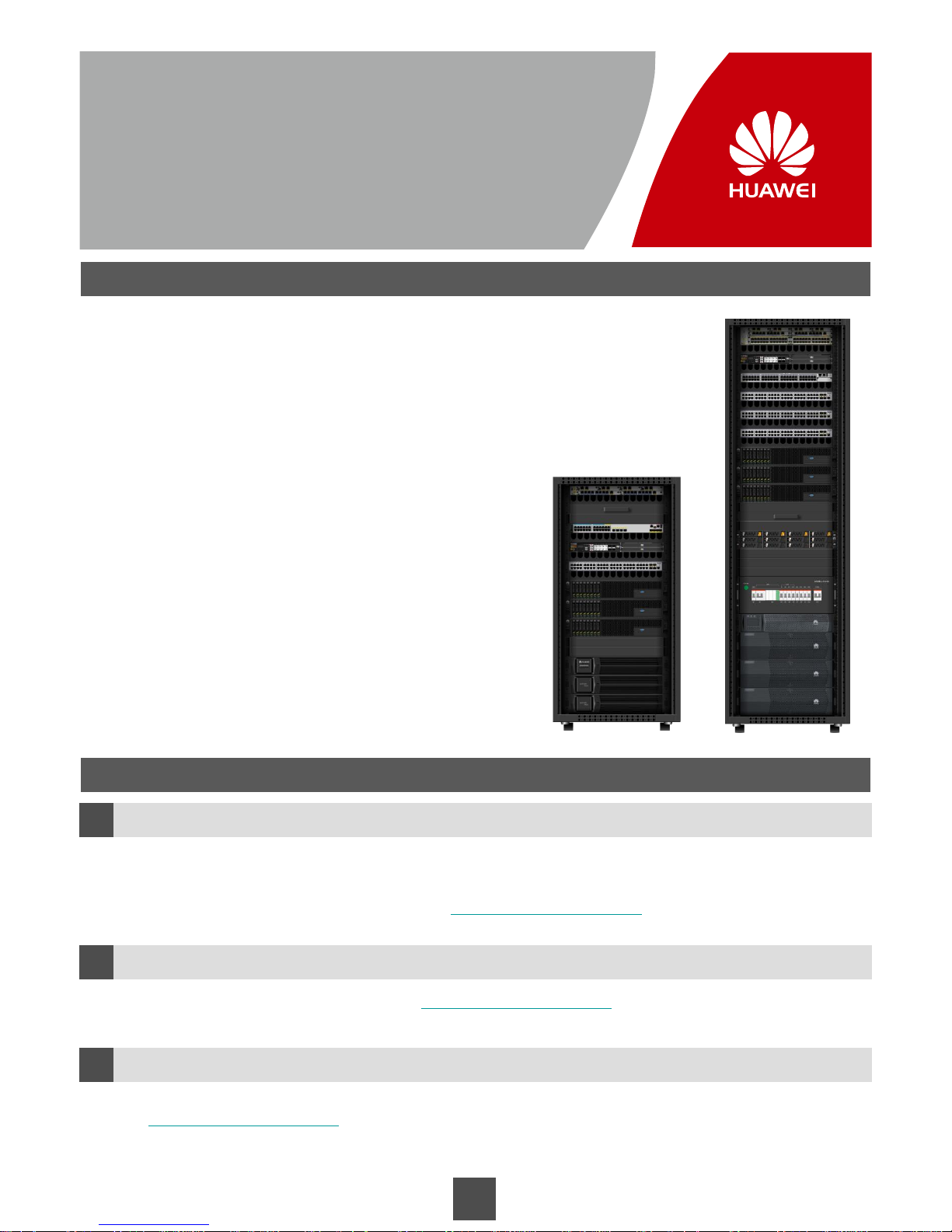
MicroDC3000L 24U
MicroDC3000H 42U
Application Scenarios
Small-scale branch offices
MicroDC3000L (a 24 U cabinet + optional devices)
Medium-sized branch offices
MicroDC3000H (a 42 U cabinet + optional devices)
The MicroDC features high scalability. Devices can be easily added
to the cabinet based on service requirements.
More MicroDC cabinets can also be added on demand.
About This Document
How to Obtain Help
a
b
Feedback
c
Before You Start
This document describes how to install MicroDC hardware devices onsite. It does not include the installation of
the devices preinstalled before delivery. For details about the installation for each device, see the documents
delivered with the devices or obtain documents at http://enterprise.huawei.com based on the device model.
You can view and download documents from http://enterprise.huawei.com after registering with this website.
Your comments and suggestions help improve the accuracy and quality of our documentation.
Visit http://enterprise.huawei.com to submit your comments and suggestions.
Copyright Huawei Technologies Co., Ltd. 2014. All rights reserved.
Page 2
DANGER
Do not operate equipment or cables during lightning strikes.
Installation Process
Safety Precautions
2
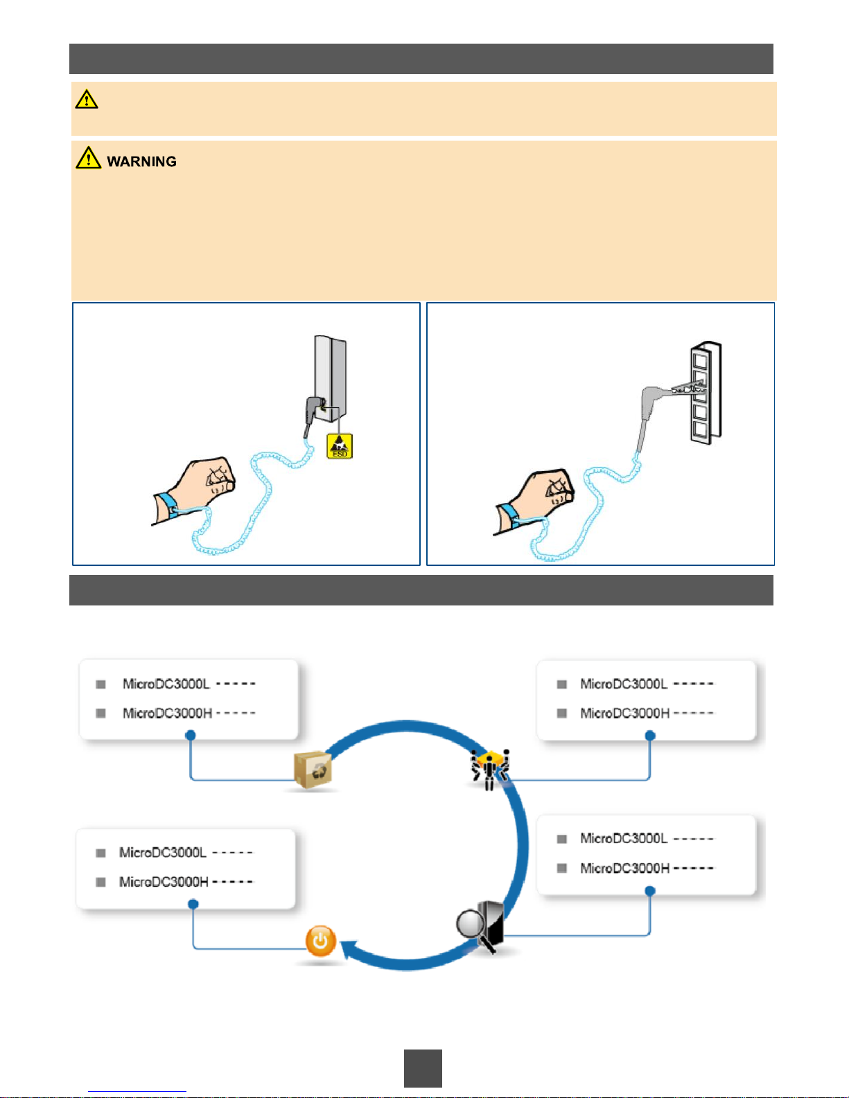
Scenario 1 Wear an ESD wrist strap inserted into
the ESD jack.
P4
P25
P8
P29
P43
P21
P45
P22
Ground a device before powering it on. Otherwise, personal injury or equipment damage may be caused
by high leakage current.
When installing equipment, ground it first. When removing equipment, disconnect grounding cables last.
Do not damage grounding conductors or operate the equipment without a grounding conductor.
Equipment must be permanently connected to the protection ground before an operation. Before operating
a device, check the electrical connection of the device and ensure that the device is securely grounded.
Scenario 2 Wear an ESD wrist strap connected
using a crocodile clip.
Preparation
Installation and cable connection
Power-on and power-off commissioning
Inspection before power-on
Page 3
3
MicroDC3000L Quick Installation Guide
Start Here
Page 4

1a
Obtaining Tools
1 Installation Preparations
4
NOTE
Ensure that the mandatory tools are available before the installation. The optional tools help increase
installation efficiency.
1b
Checking Goods
NOTE
Check the goods according to the goods list delivered with the devices.
If there are packed components that require inspections, unpack and inspect them against the packing
list delivered with the product.
If you need to inspect battery packs, see the inspection method described in the document delivered with
the battery packs (P11).
Mandatory Tools
Adjustable
wrench (6'')
Phillips
screwdriver
(M5, M6, and
M8)
Flat-head
screwdriver
(2 mm to 5
mm)
ESD gloves Measuring
tape (5 m)
Electrical
tester pen
Diagonal
pliers
Optional Tools
Right angle Level Impact tool Headlamp Niddle-nose
pliers
Socket
screwdriver
(7 mm)
Electrician's
knife
Protective
gloves
Multimeter Powder
marker
Vertical
analyzer
Claw
hammer
Page 5
5
1c
Understanding Label Specifications
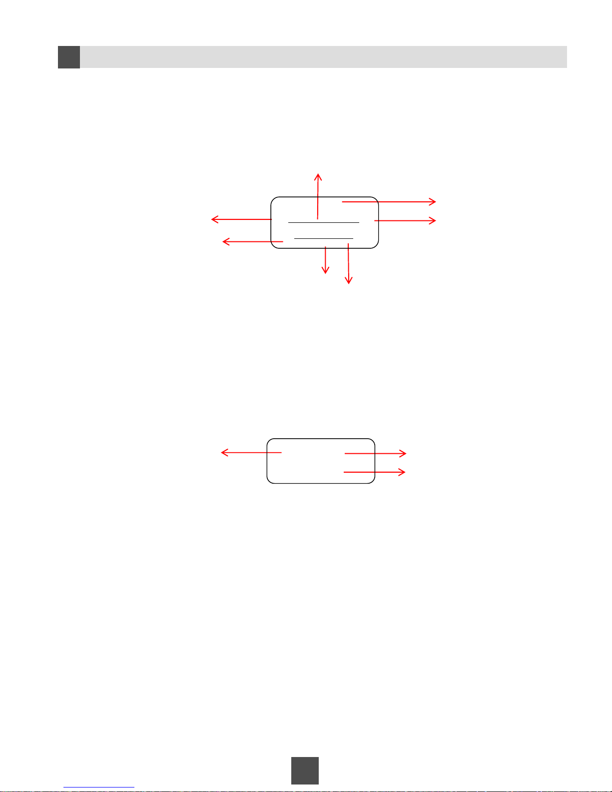
Power cable label
Example:
Network cable label
Example:
Device name
PDU slot number
Installation position
of the device
Installation position
of the peer device
Installation position of
the local device
Label description: The No.7 network cable on the FE7 port of the AR1220 router installed on the 22
U position of the rack is connected to the port GE0 of the USG installed on the 18 U position of the
rack.
To:
From:
To:
From:
Local device name
Sequential number of
the network cable
Port number of the
peer device
Port number of the local device
Peer device name
#7
22U-AR1220-FE7
18U-USG-GE0
9U-CCU
PDU-B1-5
Label description: The power cable on the No.5 slot, B1 socket of the PDU is
connect to the CCU installed on the 9 U position in the cabinet.
Page 6
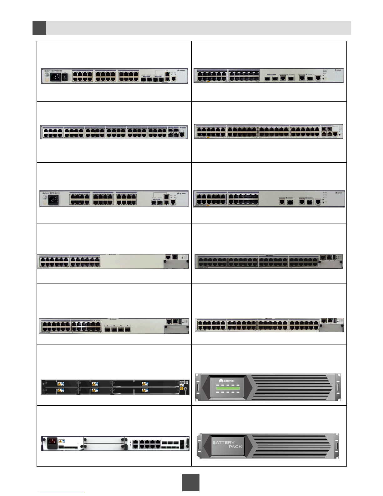
Device Appearances
1d
6
S3700-28TP-SI-AC S3700-28TP-PWR-EI
S3700-52P-SI-AC S3700-52P-PWR-EI
S2700-26TP-EI-AC S2700-26TP-PWR-EI
S5700-28C-PWR-EI S5700-52C-PWR-SI
S5700-28C-SI S5700-52C-SI
USG2260 Uninterruptible power supply (UPS)
Cabinet control unit (CCU) Battery pack
Page 7
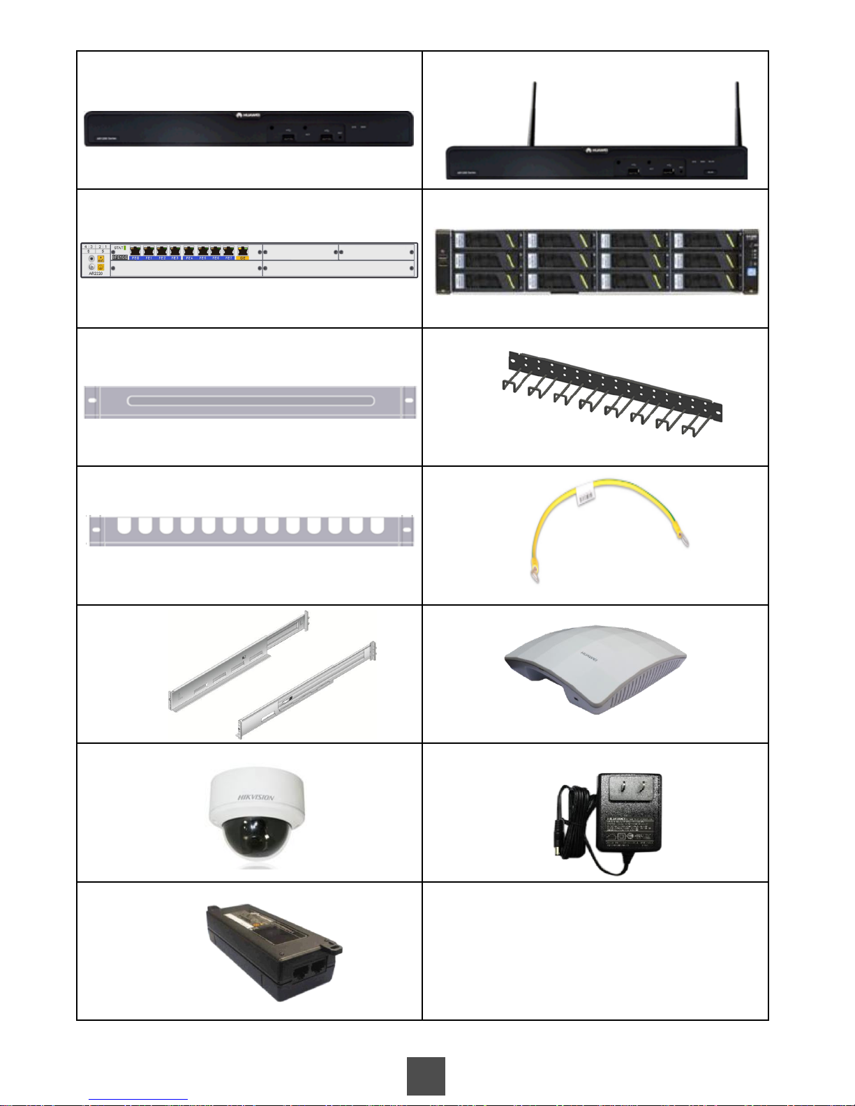
7
AR1220, AR1220V AR1220W, AR1220VW
AR2220 RH2285
Filler panel Cable rack
Cable tray Ground cable
Adjustable guide rails Access point (AP)
Dome camera AP power adapter
PoE power adapter
Page 8
8
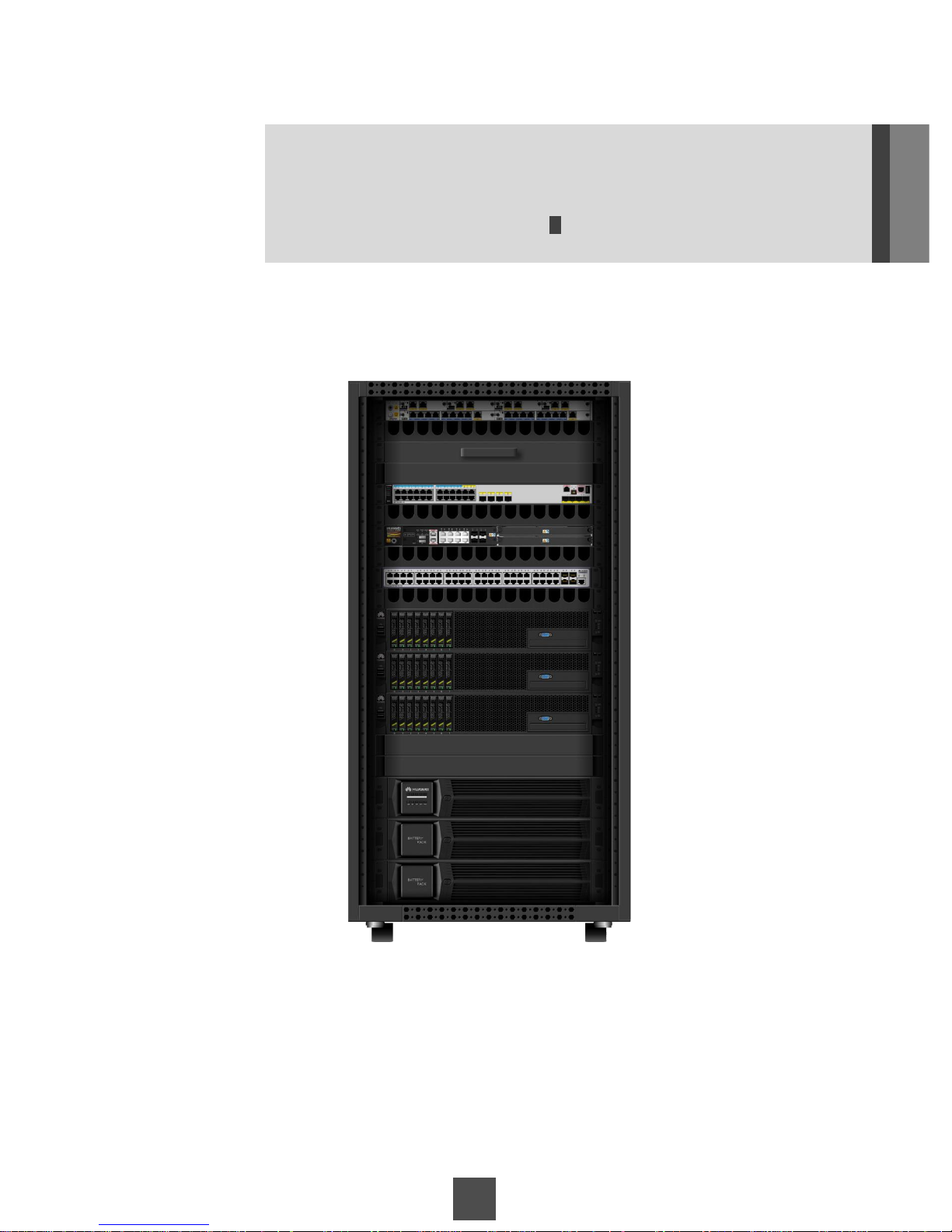
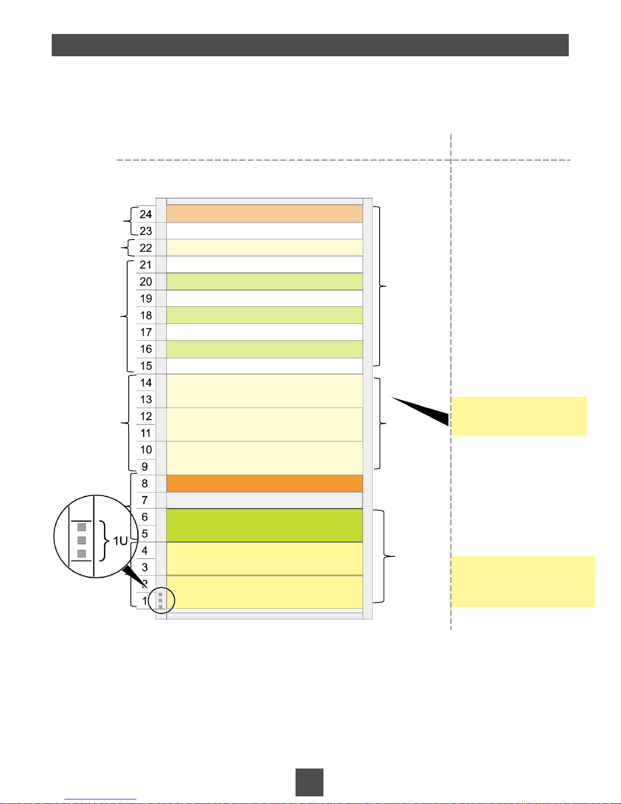
The height of the cabinet is 24 U.
Note: U is a unit of measure used to describe the height of devices in a rack. One U is 1.75 inches (44.45 mm) high.
The board layout of the MicroDC3000L suite is as follows:
Install the battery packs from
the bottom up.
Installation position Installation suggestions
CCU + Temperature and humidity sensor
UPS
Battery pack 1
Battery pack 2
Router
Cable tray
Cable tray
Server
Firewall/Access switch
Filler panel (1 U)
Server
Aggregation switch
KVM
Cable tray
Power supply
& distribution
area
Reserved
area
Network
device area
The CCU, UPS, and aggregation switch are mandatory. Other devices are optional.
The CCU, UPS, aggregation switch, and optional network devices are preinstalled before delivery.
Other devices are installed onsite.
Other components to be installed include the cameras, integrated sensor mounting arm, PoE
power adapters and APs.
Install servers here.
MicroDC3000L suite
Preinstalled
Installed onsite
Preinstalled
Installed onsite
Cable tray
Server
Cable tray
Firewall/Access switch
2 Device Installation and Cable Connection
Preinstalled
Installed onsite
Page 9
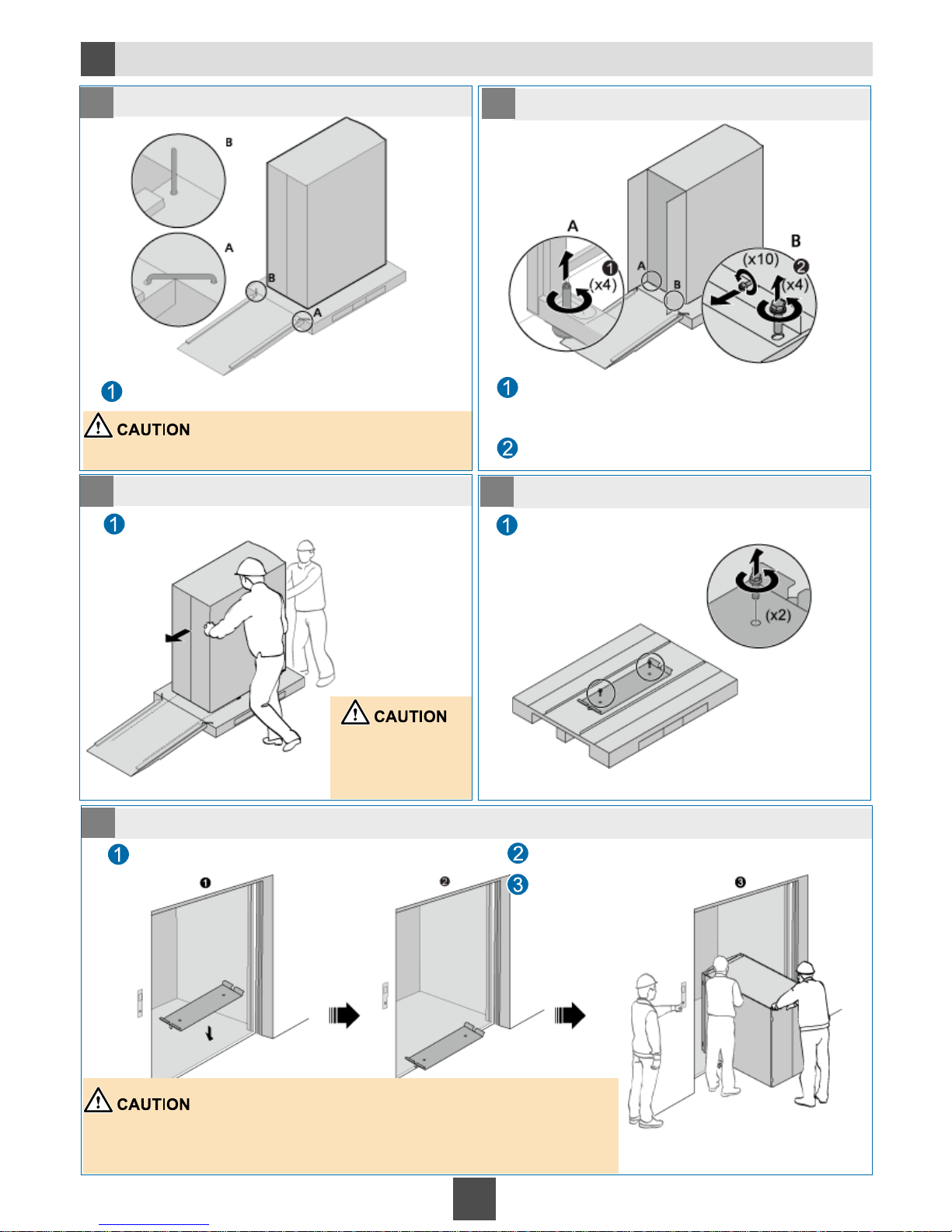
Moving the Cabinet (Moving the Cabinet with Devices Using Elevators)
2a
9
1
1 Secure the ramp in place.
2 Remove the screws from the cabinet.
Use dowels to fix one end of the ramp on the pallet
and put the other end on the ground.
1
3 Move the cabinet off the pallet.
1
4 Remove the shim from the pallet.
5 Move the cabinet into the elevator.
Do not place the ramp upside down.
Use an adjustable wrench to turn the four
supporting feet of the cabinet anticlockwise until the
leveling feet bear the whole cabinet weight.
Use an adjustable wrench to remove all screws
from the front and rear doors of the cabinet.
Push the cabinet so that it rolls down the ramp
attached to the pallet.
Two people are
required to move the
cabinet.
Use an adjustable wrench to remove the shim
from the pallet.
Place the shim on the gap of the elevator door.
Ensure that the shim is securely placed.
Push the cabinet into the elevator.
• Ensure that the shim is firmly placed and the wheels of the cabinet move along
the shim.
• Use the same way to move the cabinet into and out of the elevator.
• A dedicated person is required to open and close the elevator door.
Page 10
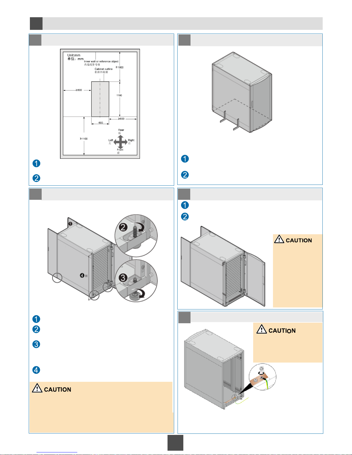
10
Connect one end of the ground cable to the ground bar of the
cabinet and the other end to the ground bar of the equipment room.
Installing the Cabinet
2b
1 Determine the cabinet installation position.
2 Place the cabinet in place.
3 Secure the cabinet in place.
4 Level the cabinet.
5 Ground the cabinet.
Determine the position for installing the cabinet based
on the engineering drawing. Mark the four corners of
the cabinet on the floor.
Use the powder marker to draw the outline of the
cabinet.
Move the cabinet in place.
Align the cabinet edges with the marks on the floor
using a right square.
Use a level and plumb line to measure the cabinet.
Ensure that the cabinet is level.
If the cabinet is not level, use an adjustable wrench
to raise or lower the leveling feet.
Open the front and rear doors.
Rotate the four leveling feet clockwise by using a Phillips
screwdriver to lower the leveling feet.
Rotate the M12 bolts at the bottom of the leveling feet
clockwise by using an adjustable wrench until the
leveling feet contact the ground and the wheels hang
in the air.
Ensure that the heights measured from the front,
rear, right, and left of the cabinet are the same.
• Spin the wheels by using a Phillips screwdriver. If the
wheels rotate freely, they are hanging in the air.
• H indicates the distance from the cabinet top to the
ground. The cabinet height can be adjusted from 1195
mm to 1205 mm with the help of the leveling feet.
Measure the front
and rear cabinet
doors as follows:
Place the level
along the surface
of the cabinet. If
the air bubble
goes to the center
of the clear tube,
the surface is even.
ground bar of the
equipment room
This operation must be
performed by professional
electricians onsite.
Page 11
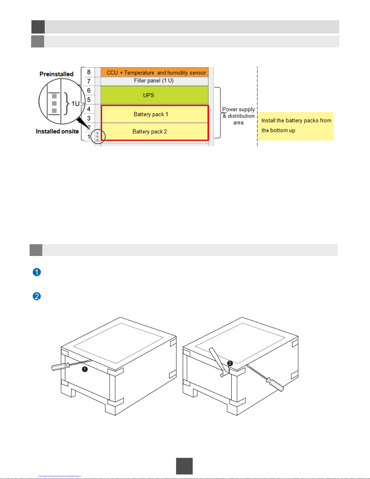
Installing Battery Packs
2c
11
Due to the limited length of cables, if only one battery pack is required, place it in the position of
battery pack 1.
1 Determine installation positions.
2 Unpack battery packs.
Hold a claw hammer with one hand to support the cover, and hold the screwdriver with the other
hand to turn the cover upwards along the external side until the cover is removed from the body.
Insert a flat-head screwdriver into the gap between the cover and body of the wooden crate, and
raise the cover upwards.
Page 12
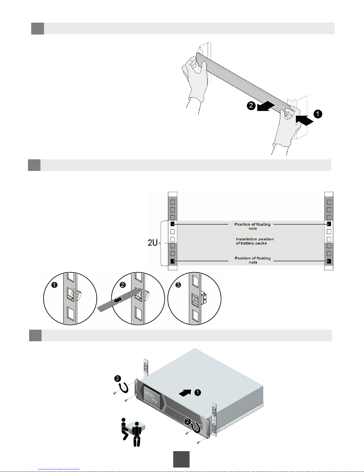
12
4 Install floating nuts.
5 Install battery packs in the rack.
3 Remove the filler panel.
Hold one side of the filler panel with one
hand, and hold the buckle on the other side
of the filler panel with the other hand, press
the buckle with the middle finger, and pull
out the filler panel with proper force.
Use the floating nut installation bar to install the floating nuts on the tapped hole of the mounting bar
inside the cabinet.
The figure on the right shows the positions
of the floating nuts.
Installation method:
Page 13
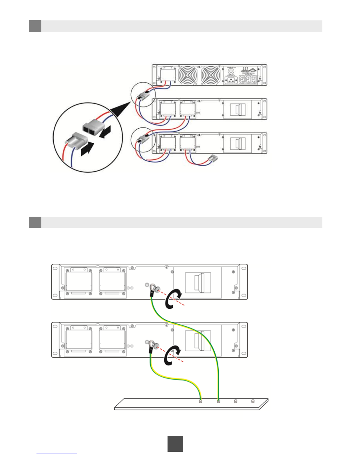
13
6 Connect the UPS with the battery packs.
7 Ground battery packs.
Insert the ground cables reserved on the ground bar into the binding posts of the three
battery packs, and fasten the screws.
Battery pack 1
Battery pack 2
Ground bar
UPS
Battery
pack 1
Battery
pack 2
Do not connect the
plug on the right.
Page 14
2d
Installing the Server (The RH2285 is used as an example.)
14
NOTE
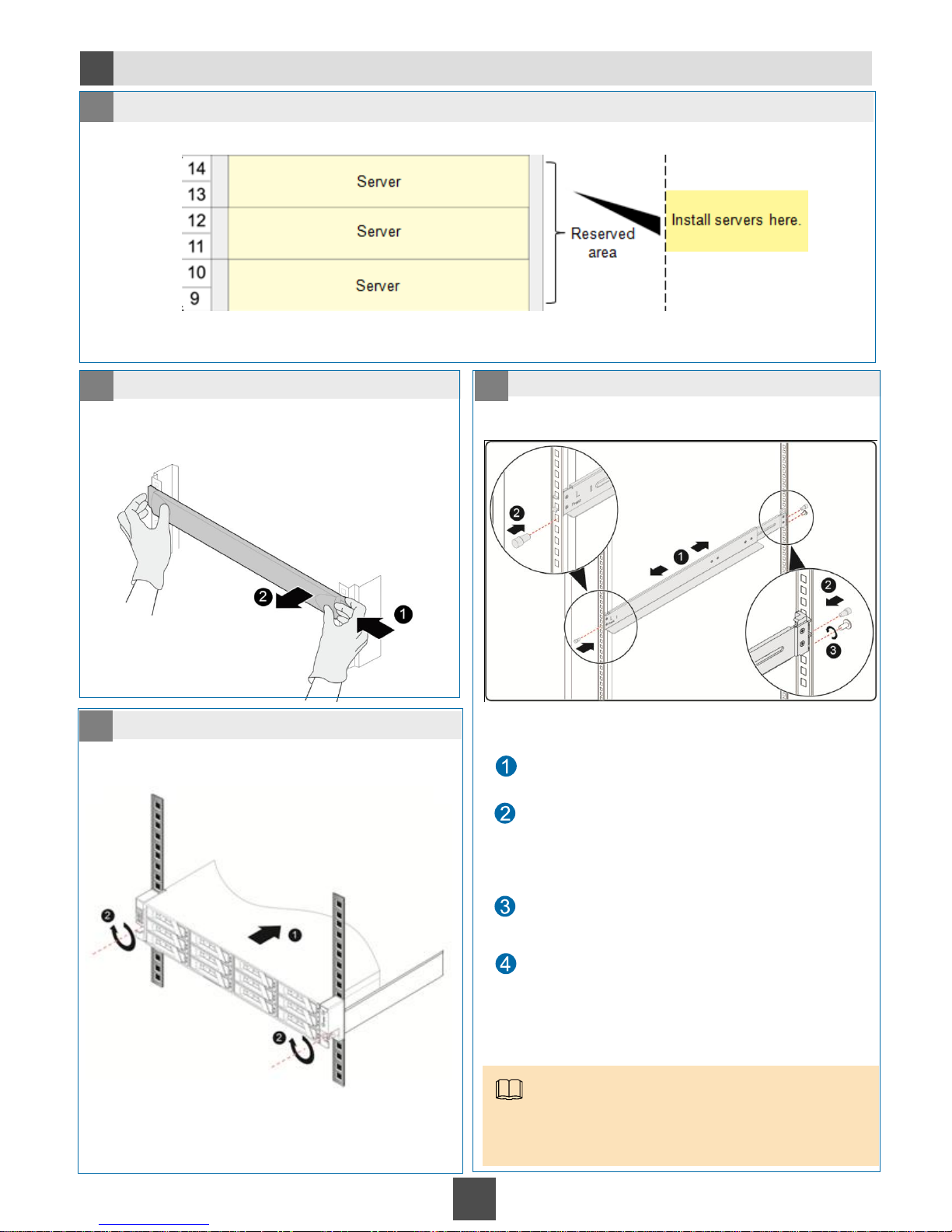
Guide rails are preinstalled at the 9 U to 10 U height before delivery.
You only need to install guide rails at 11 U to 12 U and 13 U to 14 U.
1 Determine the installation position.
2 Remove the filler panel. 3 Install guide rails.
4 Install the server in the rack.
Hold one side of the filler panel with one hand, and
hold the buckle on the other side of the filler panel
with the other hand, press the buckle with the middle
finger, and pull out the filler panel with proper force.
Place the guide rail horizontally at the planned
position near the rack installation bar and hook the
buckle.
Insert the rubber plugs delivered with the guide rails
into the following square holes to fasten the guide
rails:
•Square hole at the front bottom of the guide rail
•Square hole in the rear middle of the guide rail
Insert an M6 screw to the first square hole at the rear
of the guide rail and fasten the M6 screw.
Use the same method to install the guide rail on the
other side of the server.
Page 15
NOTE
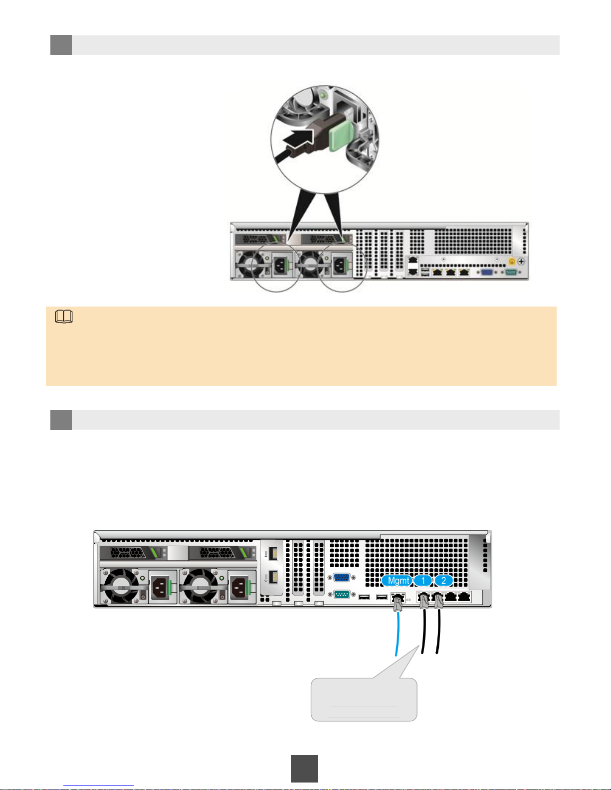
Connect the two reserved power cable connectors on the PDU to the server based on labels. Make sure that
the installation position on the label is the same as the server.
No ground cable is required because the RH2285 is configured with AC power modules.
15
5 Connect power cables.
6 Connect the switch and the server.
Find the network cables from the switch based on the labels and connect the network cables to the
corresponding ports on the server.
RH2285H
#9
9/10U-Server-1
20U-S5700-G09
Lable example:
Page 16
2e
Installing the KVM
16
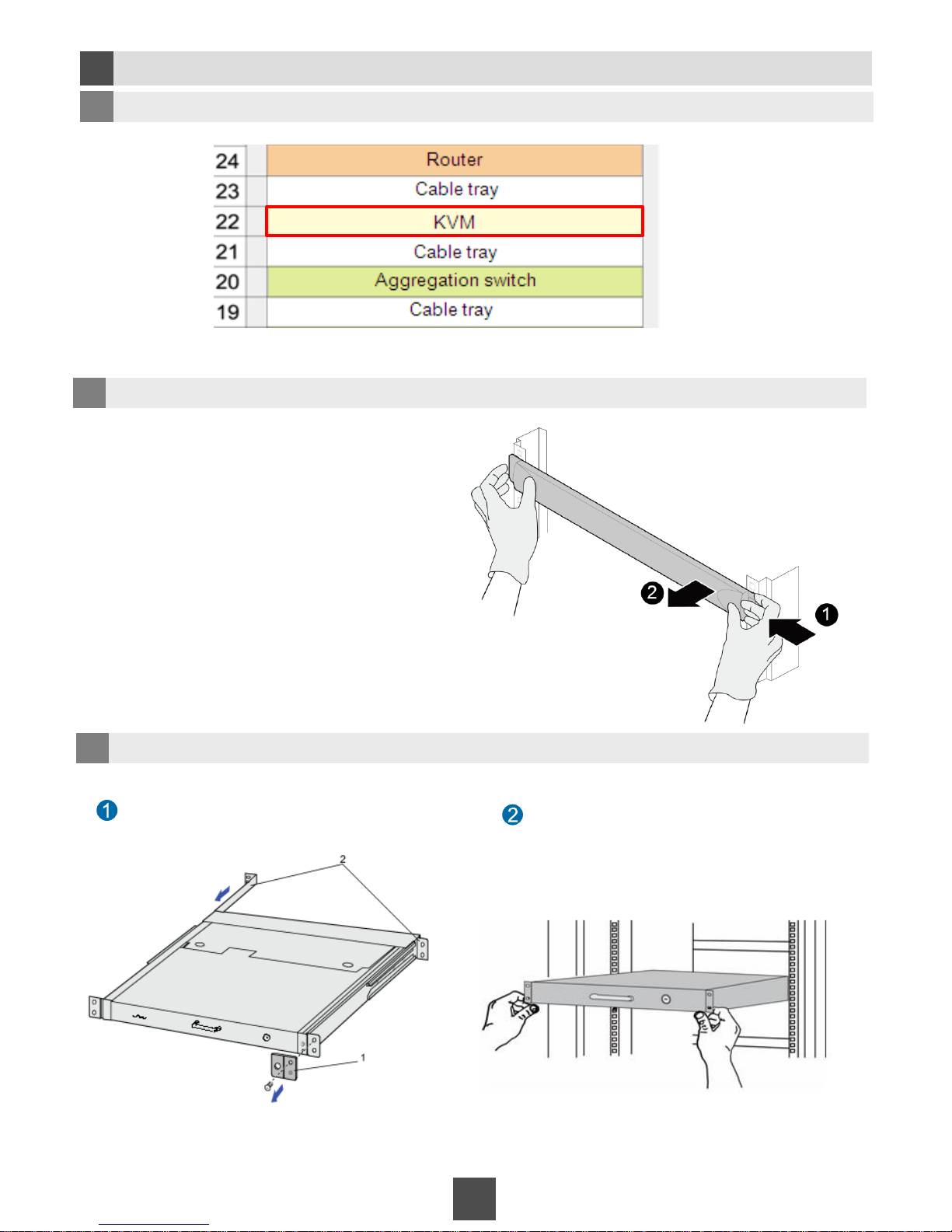
1 Determine the installation position.
2 Remove the filler panel.
3 Install the KVM.
Hold one side of the filler panel with one
hand, and hold the buckle on the other side
of the filler panel with the other hand, press
the buckle with the middle finger, and pull out
the filler panel with proper force.
Remove the shipping bracket from the KVM
front panel.
Place the KVM on the guide rails from the
front of the cabinet and slide it into the right
position.
Page 17
17
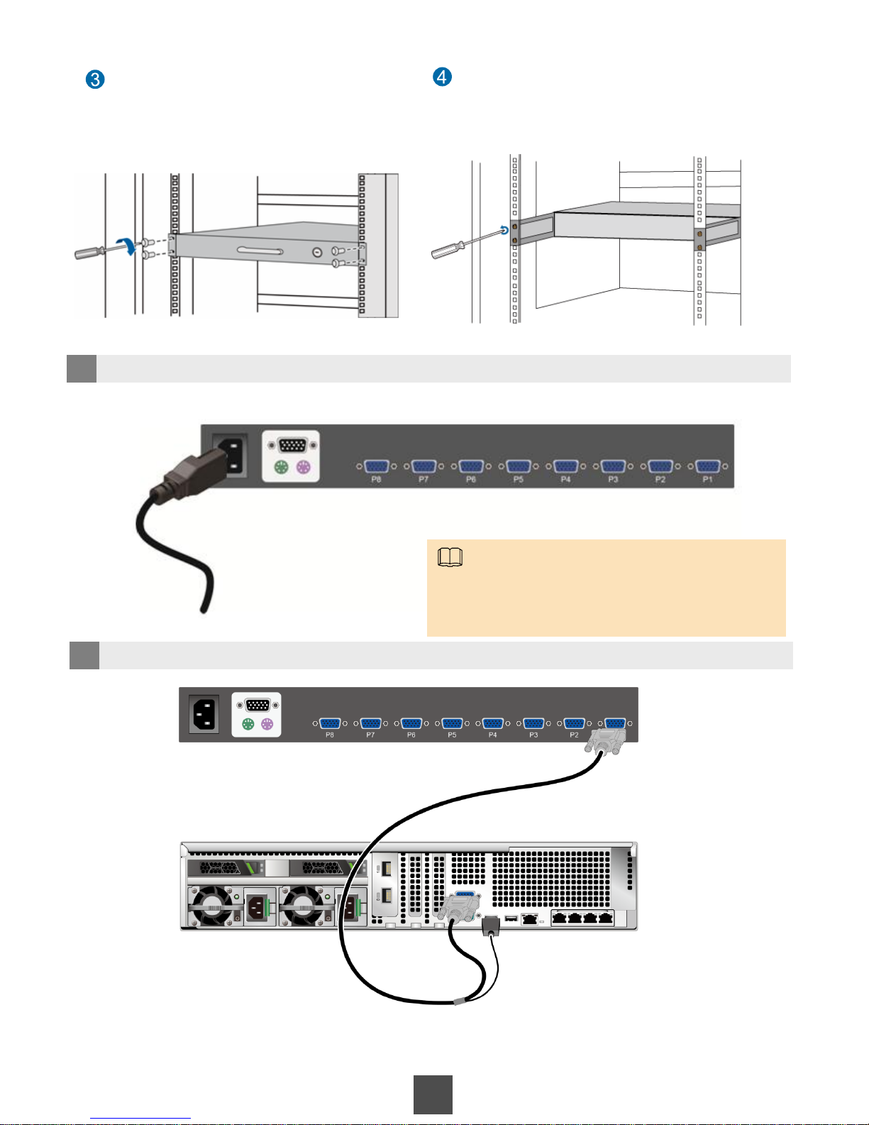
Use screws to fasten the front mounting
ears of the KVM to the mounting bars of
the cabinet.
Insert rear mounting ears to the rear
mounting ear conduits, and use screws to
secure the rear mounting ears to the
mounting bars of the cabinet.
4 Connect the KVM to the PDU.
5 Connect the KVM to servers.
To facilitate subsequent maintenance, connect the servers in the rack to the eight KVM ports
(numbered from P1 to P8) from the bottom up.
NOTE
Connect the reserved power cable connector on the
PDU to the KVM. No ground cable is required because
the KVM is configured with AC power modules.
Page 18
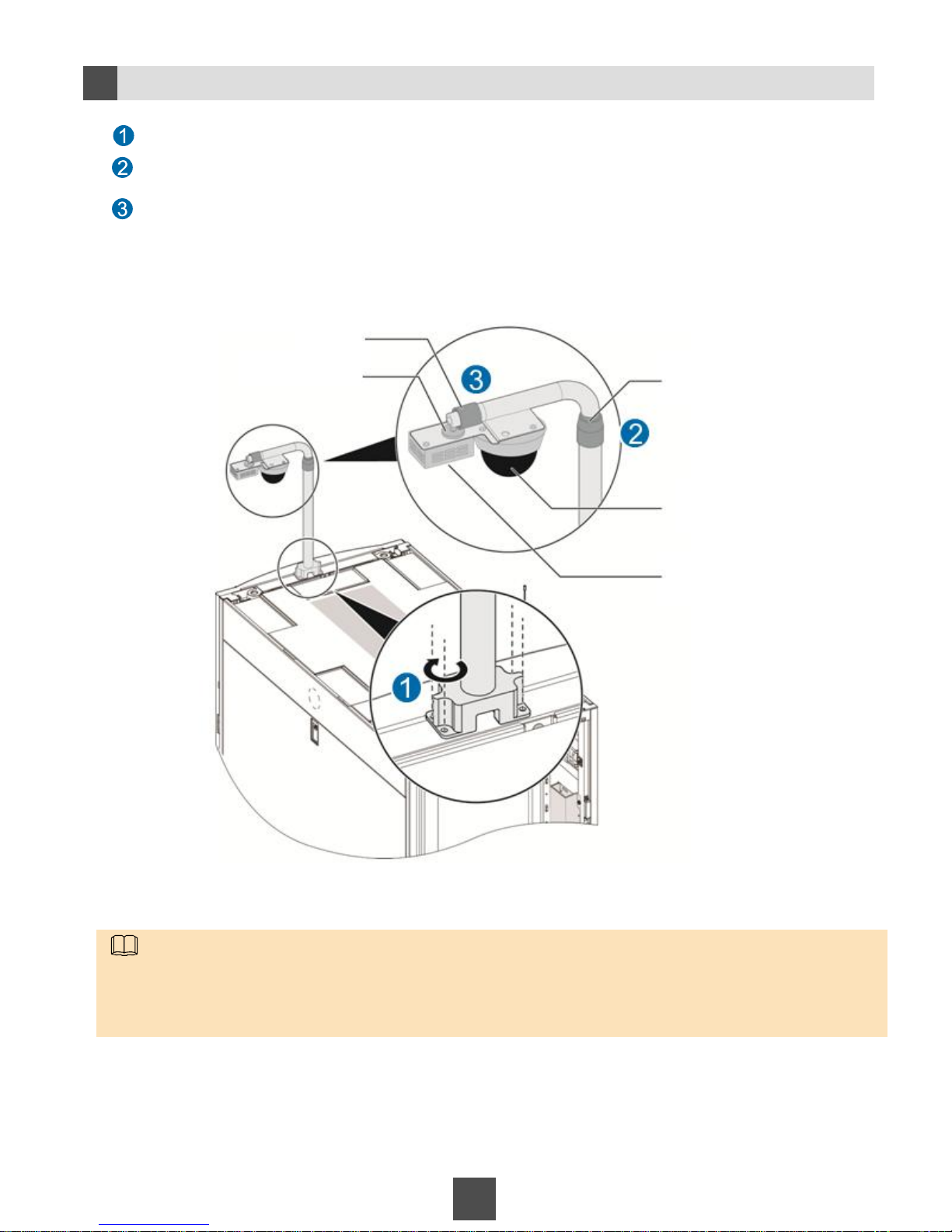
18
Securing the Integrated Sensor Mounting Arm
2f
Secure the integrated sensor mounting arm using the M5 Phillips screwdriver.
Rotate tube 1 to adjust the sensor mounting arm.
Adjust the angles of the smoke sensor and the camera using the rotatable connector, and secure the rotatable
tube 2.
NOTE
• Two people are required to install the integrated sensor mounting arm with the help of a step ladder.
• Use an M5 Phillips screwdriver to secure self-tapping screws for the integrated sensor mounting arm base.
• Rotate tube 1 to adjust the sensor mounting arm until it is in the highest position. Then adjust the camera based
on the object to be monitored.
Tube 1
Tube 2
Camera
Smoke sensor
Adjustable connector
Page 19
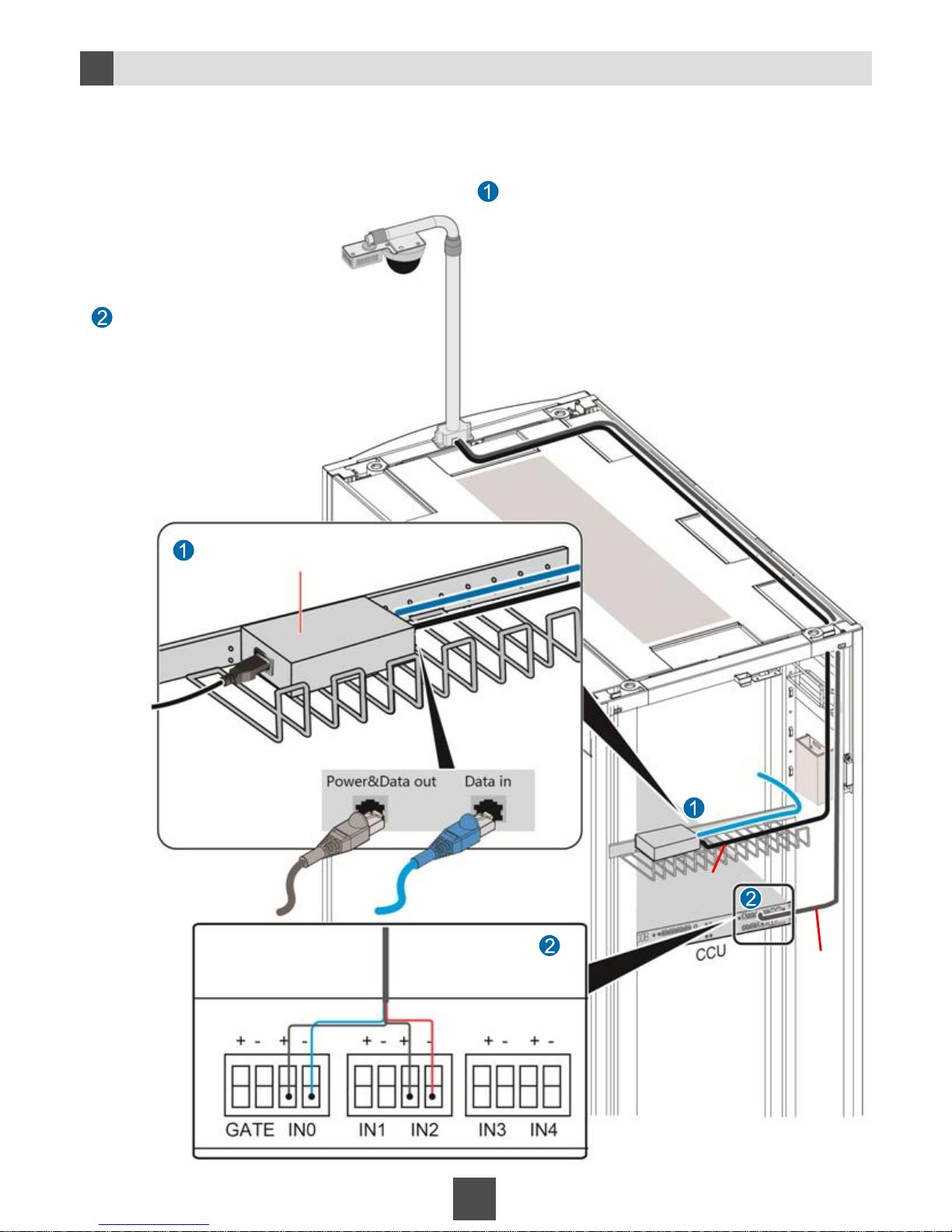
2g
Connecting Cables to the Camera
19
• The sensor mounting arm provides a network cable and a signal cable.
• The signal cable provides two camera signal cables and two smoke sensor signal cables.
• Connect the camera network cable to the PoE power adapter, and connect the camera single cables to
the CCU.
Connect the signal cables to the ports
on the CCU according to the labels on
the signal cables.
1. Place the PoE power adapter on the 17 U cable rack at the
rear of the cabinet.
2. Insert the reserved PDU power plug near the cable rack to
the power adapter.
3. Connect the network cable of the camera to the
Power&Data out port on the PoE power adapter.
4. Connect the network cable reserved for the switch near
the cable rack to the Data in port.
5. Secure the PoE power adapter using cable ties.
Connect the network cable to the camera.
Connect the signal cables to the camera.
CCU rear view
Camera signal
cables (camera)
Smoke sensor signal
cables(smoke)
Network cable
reserved for the
switch
Camera
network cable
PoE power adapter
Camera signal
cables
Page 20
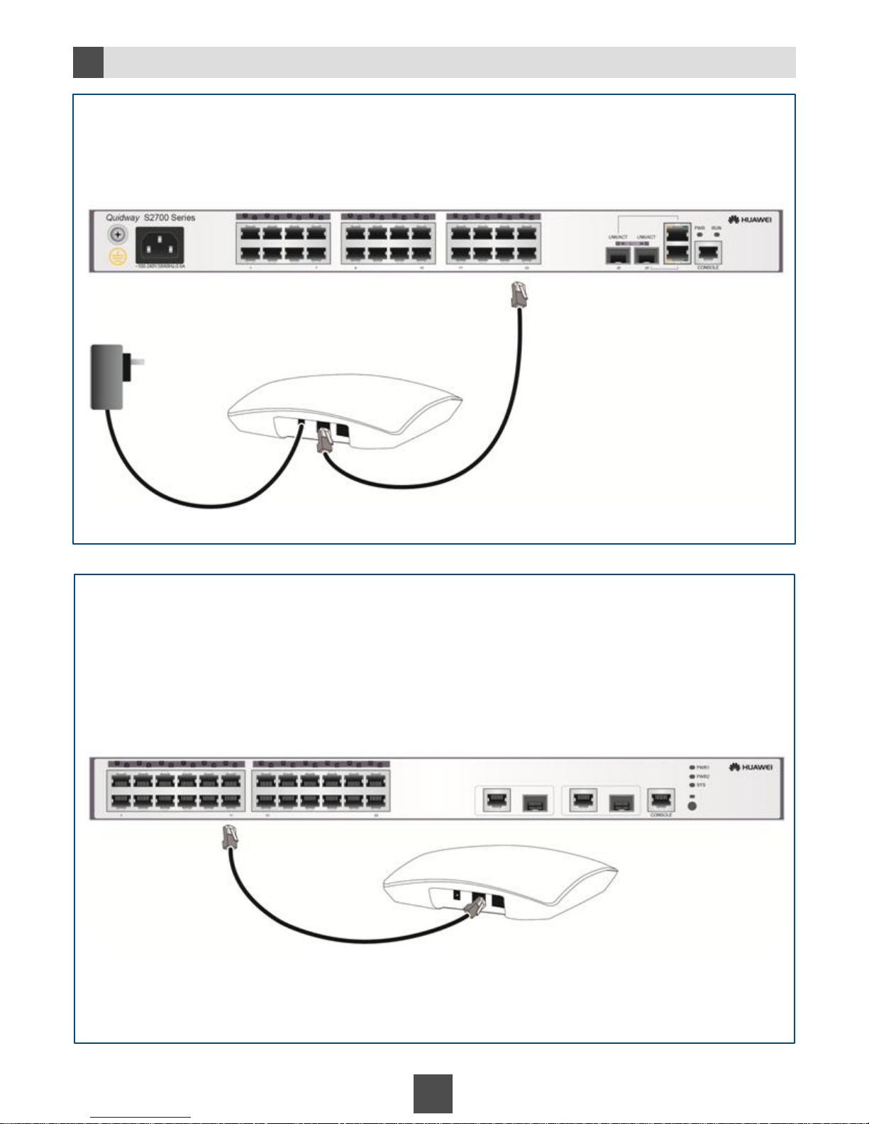
2h
Installing the AP
20
Scenario 1 AP with a power adapter
The AP obtains power using the power adapter.
Scenario 2 AP without a power adapter
The AP is connected to a switch with PoE function.
The AP obtains power by connecting to a network cable.
Connect the AP to the switch based on the network plan.
Connect the AP to the switch with the PoE function
based on the network plan.
Network cable
Power
adapter
Connecting the power
adapter to a mains power
socket
Switch
Network cable
PoE switch
Page 21
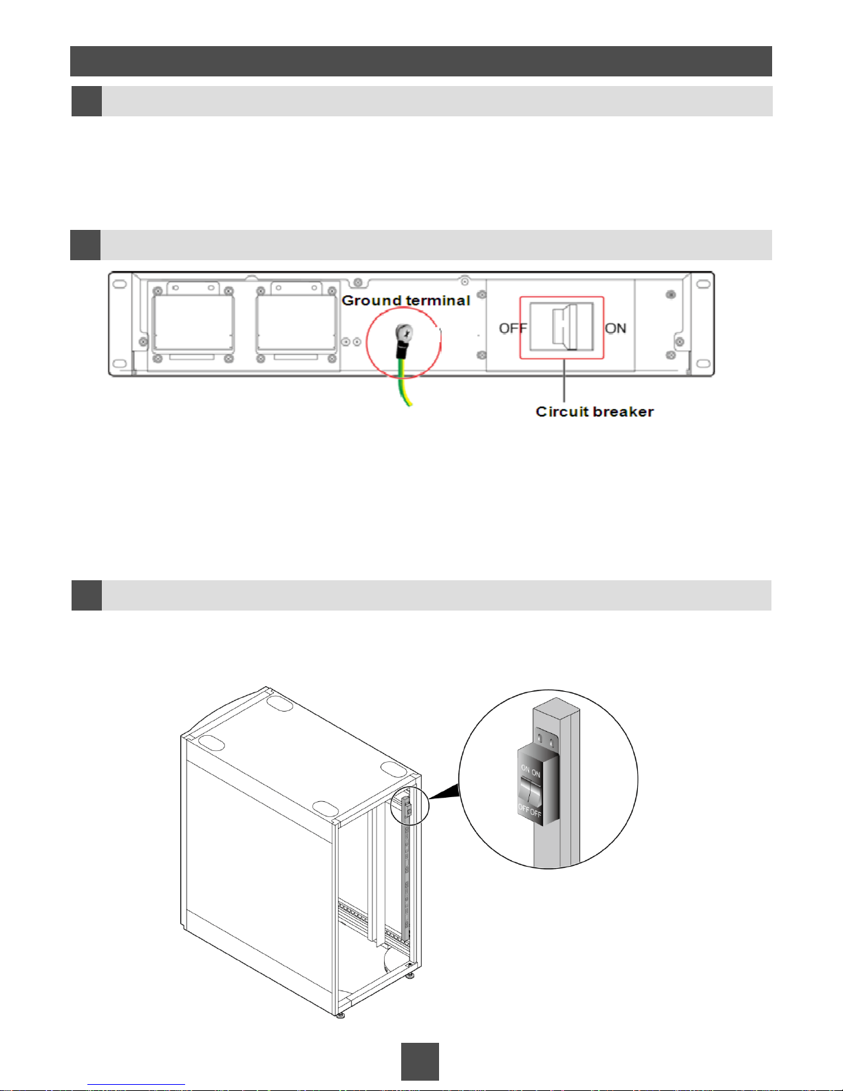
21
3 Inspecting Devices Before Power-On
Checking the UPS
3a
1. Check that all bolts are secured for cables. Fasten the bolts that are not properly
secured.
2. Check that the voltage between the mains input neutral wire and the ground cable
is less than 5 V AC.
1. Switch on and off all circuit breakers three times. Ensure that they can be switched on and off
smoothly.
2. Check that all bolts are secured for cables. Fasten the bolts that are not properly secured.
3. Switch on the circuit breaker on the battery pack. Check that the voltage between the positive and
negative terminals is greater than 96 V DC. Switch off the circuit breaker on the battery pack after
the test.
4. Check that screws at the ground points of the battery packs are secured. Fasten the screws that
are not properly secured.
1. Switch on and off all input circuit breakers three times. Ensure that they can be switched on and
off smoothly.
2. Check that all bolts are secured for cables. Fasten the bolts that are not properly secured.
3b
Checking the Battery Pack
Checking the PDU
3c
Page 22
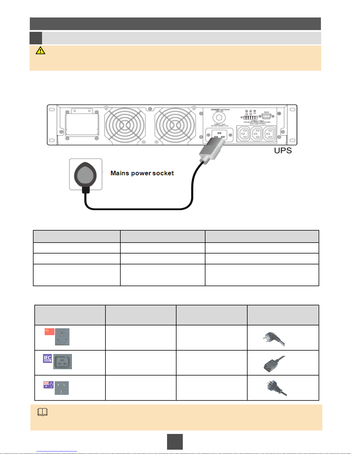
Socket Product Standards
Performance
Specifications
Plug
GB1002 16 A 250 V AC
IEC320 C19 16 A 250 V AC
AS/NZS 3112 10 A 250 V AC
4 Performing Power-On Commissioning
22
4a
Connecting the Power Cable of the Cabinet
Electrical specifications for the external mains power distribution system
Connect one end of the power cable delivered with the cabinet to the AC input socket of the UPS and
the other end to the mains power socket.
WARNING
Ground the equipment before powering it on. Otherwise, personal injury or equipment damage may
be caused by high leakage current.
NOTE
The power cable for a 24 U cabinet varies according to the port format. MicroDCs provide a variety of power
cable plugs to meet requirements in different countries.
Specifications of plugs provided by Huawei
Parameter Value Remarks
Input voltage 176 V to 264 V AC
Maximum input current 16 A
Input circuit breaker 16 A/1 P The input ports are chosen based on the
country to which the MicroDC is delivered.
Page 23
23
4b
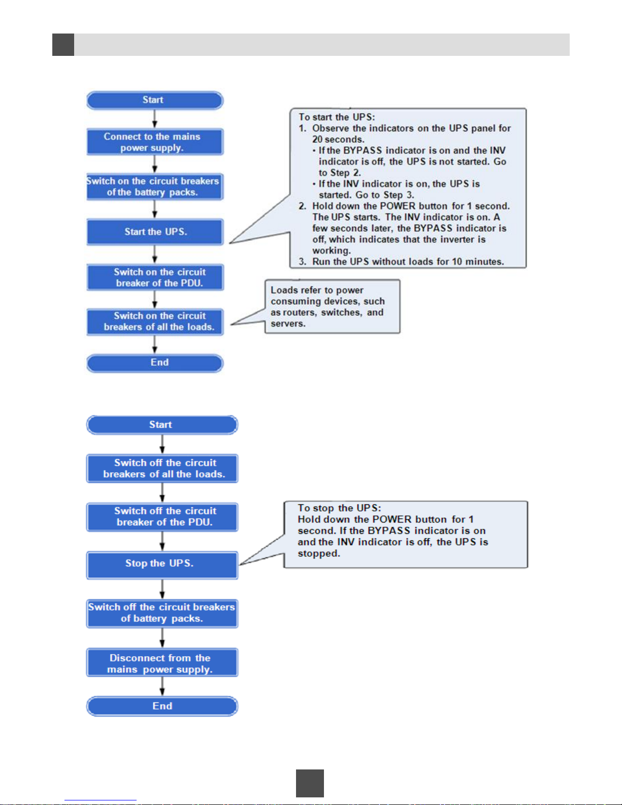
Performing Power-On and Power-Off Commissioning
Power-on process
Power-off process
The hardware installation of the MicroDC3000L suite is complete. For
subsequent operations, see Appendix.
Page 24
24
MicroDC3000H Quick Installation Guide
Start Here
Page 25
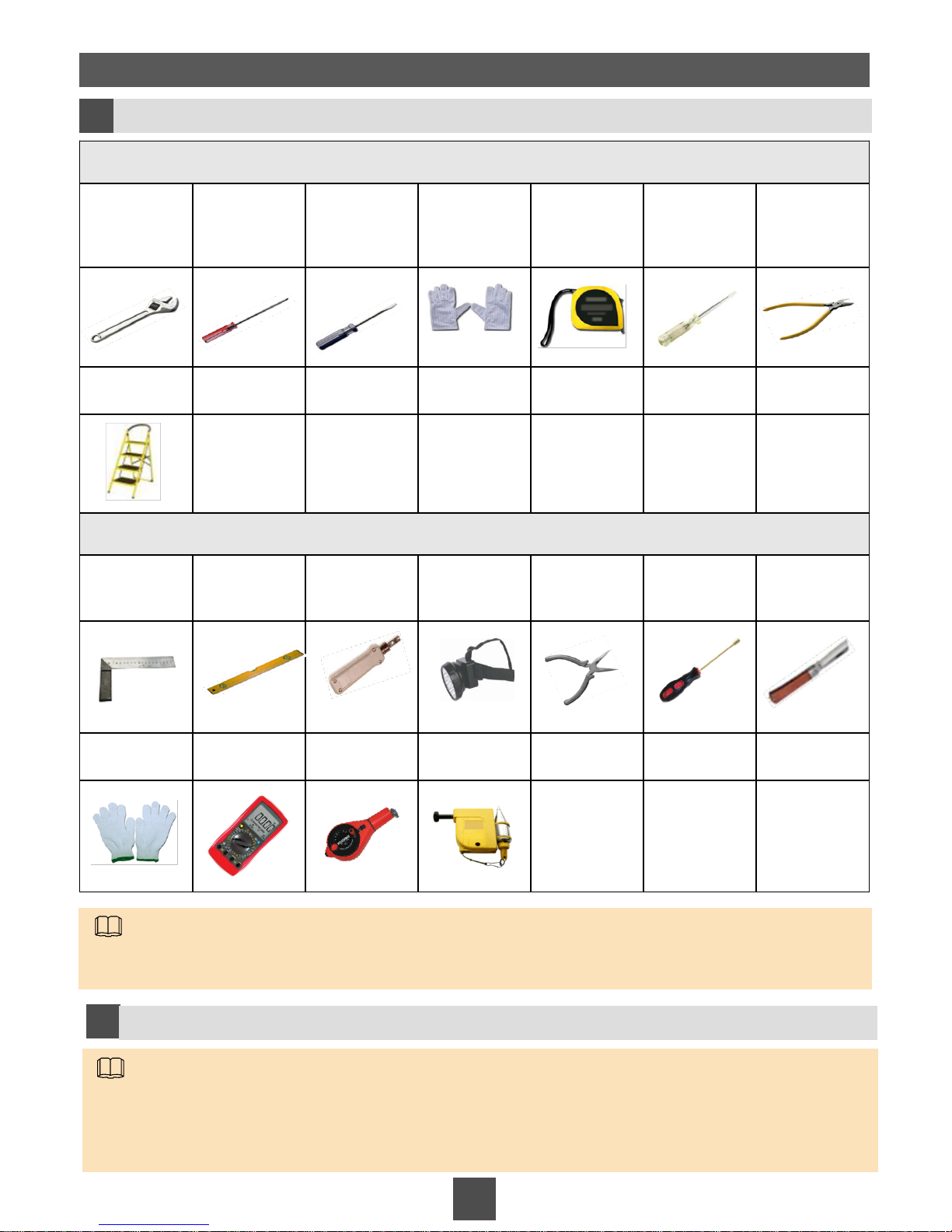
Mandatory Tools
Adjustable
wrench (6'')
Phillips
screwdriver
(M5, M6, and
M8)
Flat-head
screwdriver
(2 mm to 5
mm)
ESD gloves Measuring
tape (5 m)
Electrical
tester pen
Diagonal
pliers
Step ladder
(2 m)
Optional Tools
Right angle Level Impact tool Headlamp Niddle-nose
pliers
Socket
screwdriver
(7 mm)
Electrician's
knife
Protective
gloves
Multimeter Powder
marker
Vertical
analyzer
1a
Obtaining Tools
1 Installation Preparations
25
NOTE
Ensure that the mandatory tools are available before the installation. The optional tools help increase
installation efficiency.
1b
Checking Goods
NOTE
Check the goods according to the goods list delivered with the devices.
If there are packed components that require inspections, unpack and inspect them against the packing
list delivered with the product.
Page 26
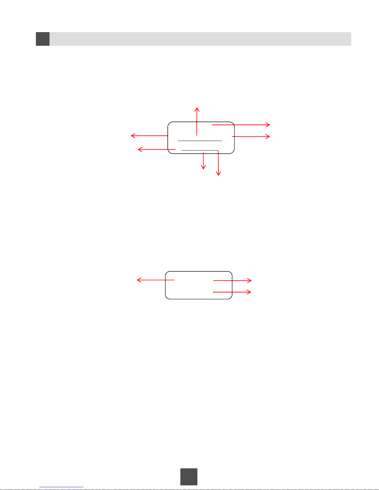
26
1c
Understanding Label Specifications
Power cable label
Example:
Network cable label
Example:
Device name
PDU slot number
Installation position
of the device
Local device name
Sequential number of
the network cable
Installation position
of the peer device
Port number of the
peer device
Installation position of
the local device
Port number of the local device
Peer device name
Label description: The No.7 network cable on the FE7 port of the AR1220 router installed on the 22
U position of the rack is connected to the port GE0 of the USG installed on the 18 U position of the
rack.
To:
From:
To:
From:
#7
22U-AR1220-FE7
18U-USG-GE0
9U-CCU
PDU-B1-5
Label description: The power cable on the No.5 slot, B1 socket of the PDU is
connect to the CCU installed on the 9 U position in the cabinet.
Page 27
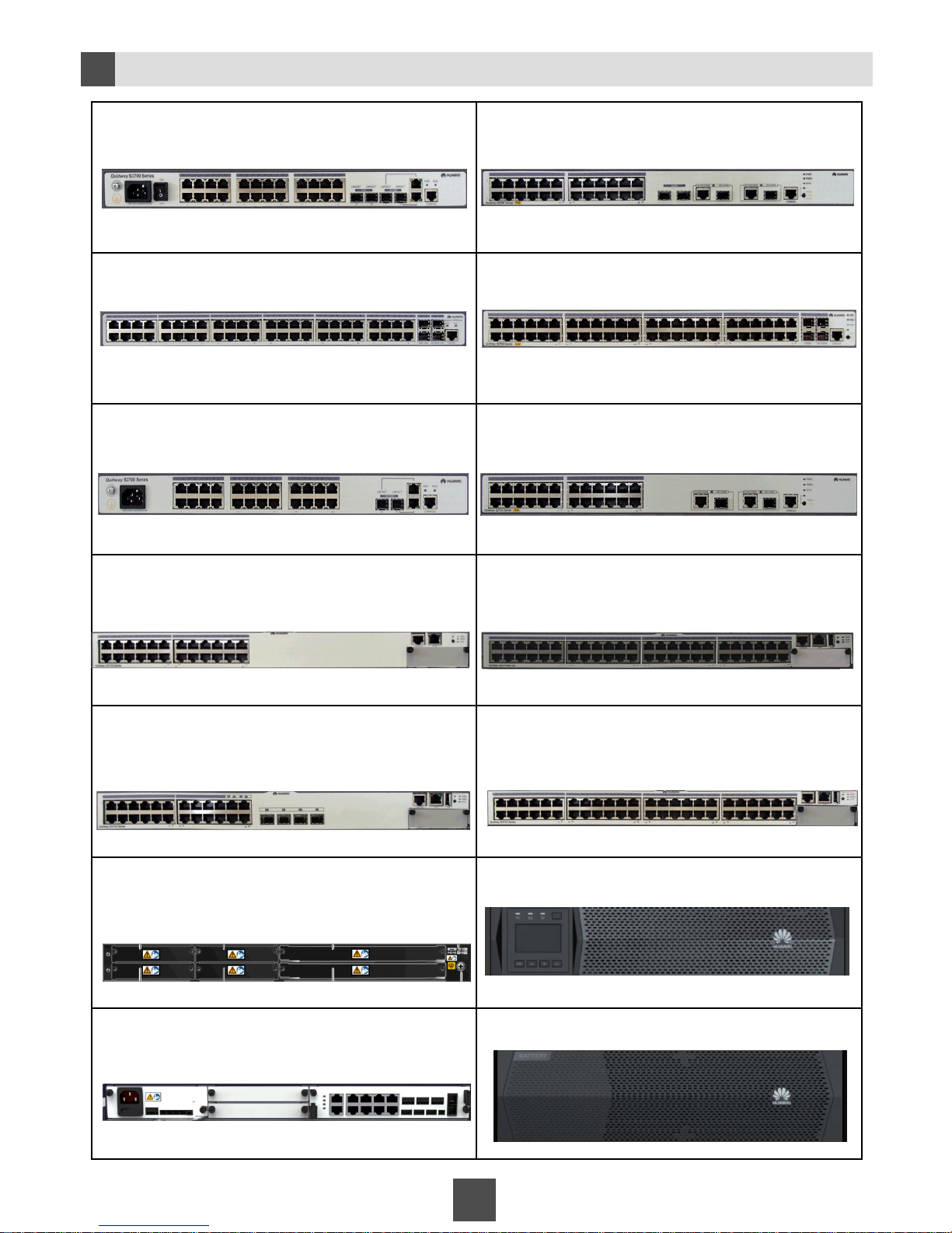
Device Appearances
1d
27
S3700-28TP-SI-AC S3700-28TP-PWR-EI
S3700-52P-SI-AC S3700-52P-PWR-EI
S2700-26TP-EI-AC S2700-26TP-PWR-EI
S5700-28C-PWR-EI S5700-52C-PWR-SI
S5700-28C-SI S5700-52C-SI
USG2260 UPS
CCU Battery pack
Page 28
28
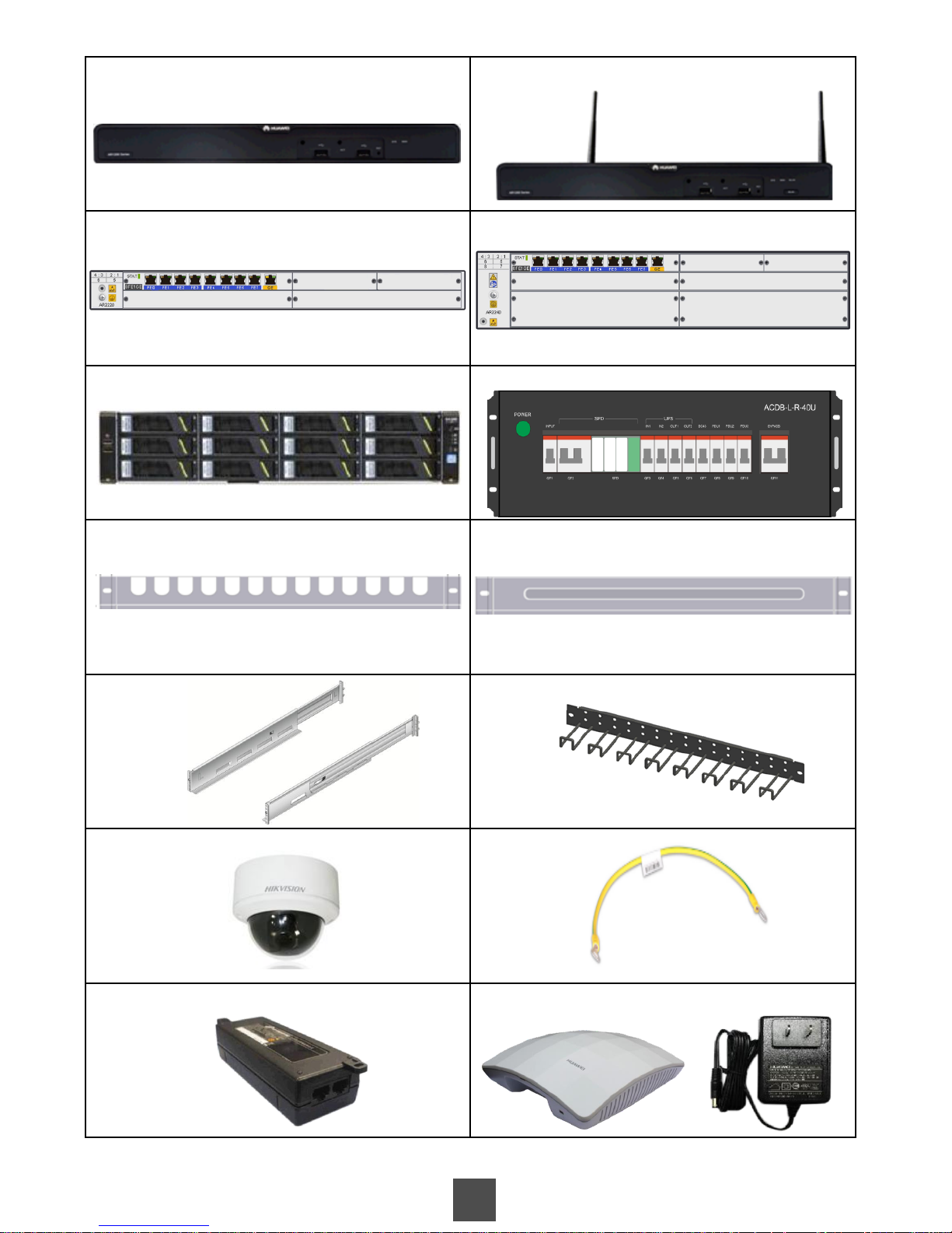
AR1220, AR1220V AR1220W, AR1220VW
AR2220 AR2240
RH2285 Power distribution box (PDB)
Cable tray Filler panel
Adjustable guide rails Cable rack
Dome camera Ground cable
PoE power adapter AP & AP power adapter
Page 29
29
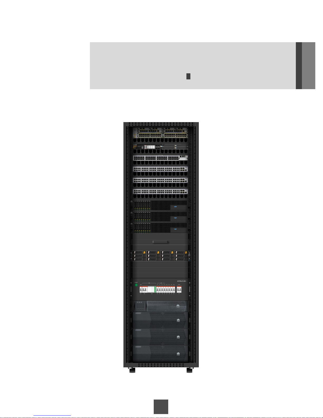
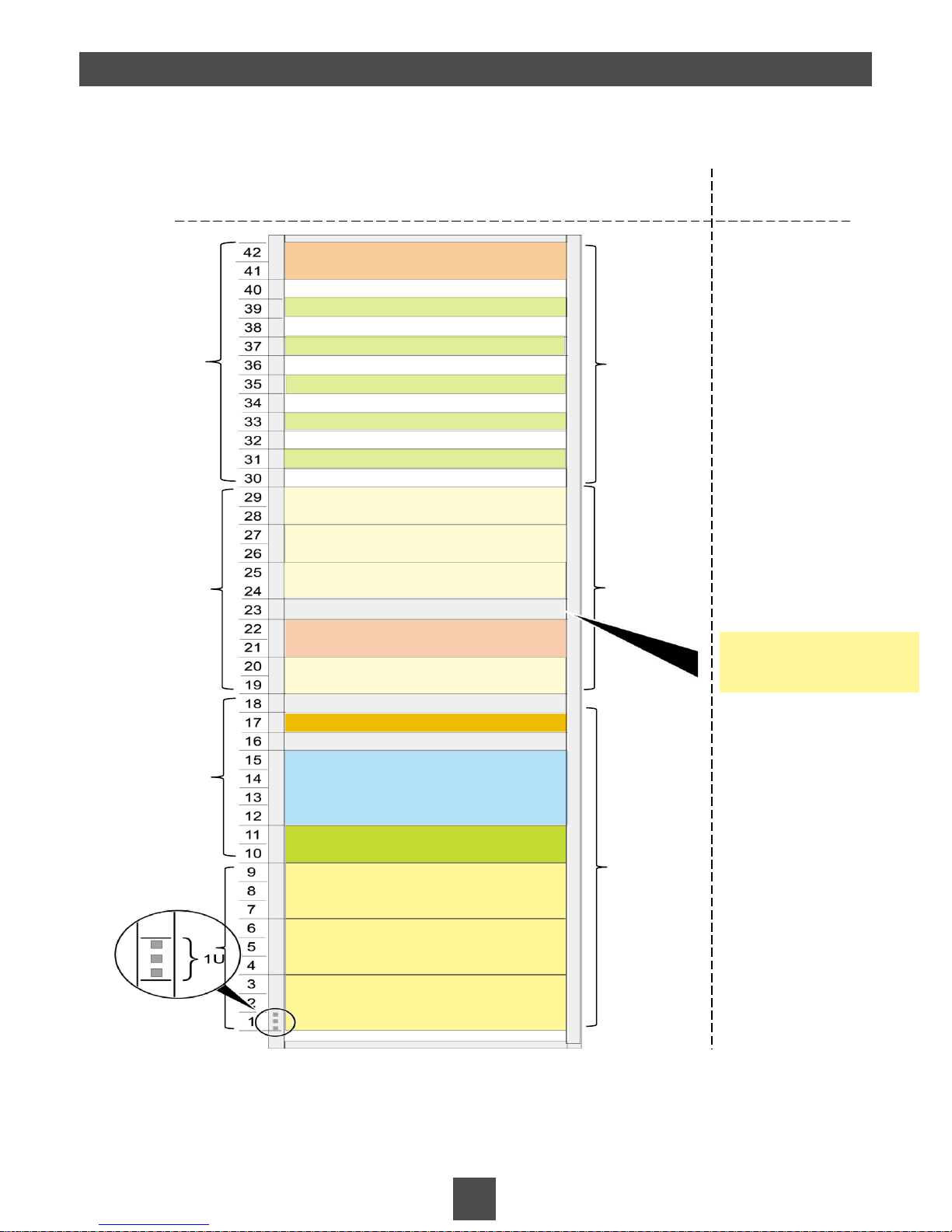
The height of the cabinet is 42 U.
Note: U is a unit of measure used to describe the height of devices in a rack. One U is 1.75
inches (44.45 mm) high.
The board layout of the MicroDC3000L suite
2 Device Installation and Cable Connection
Installation position
Installation suggestions
CCU + Temperature and humidity sensor
UPS
Battery pack 1
Battery pack 2
Battery pack 3
Access switch
Firewall
Cable tray
Access switch
Filler panel (1 U)
Cable tray
Aggregation switch
Cable tray
Power supply
& distribution
area
Reserved
area
Network
device area
Filler panel (1 U)
Router
Cable tray
Cable tray
Cable tray
Access switch
Filler panel (1 U)
Storage device (2 U)
The CCU, UPS, PDB, and aggregation switch are mandatory. Other devices are optional.
The CCU, UPS, PDB, aggregation switch, and optional network devices are preinstalled
before delivery. Other devices are installed onsite.
Servers and storage devices
can be installed here.
Preinstalled
Preinstalled
Installed onsite
PDB
Server (2 U)
KVM/Server (2 U)
Server (2 U)
Server (2 U)
Installed onsite
Other components to be installed include the cameras, integrated sensor mounting arm,
PoE power adapters and APs.
Page 30
30
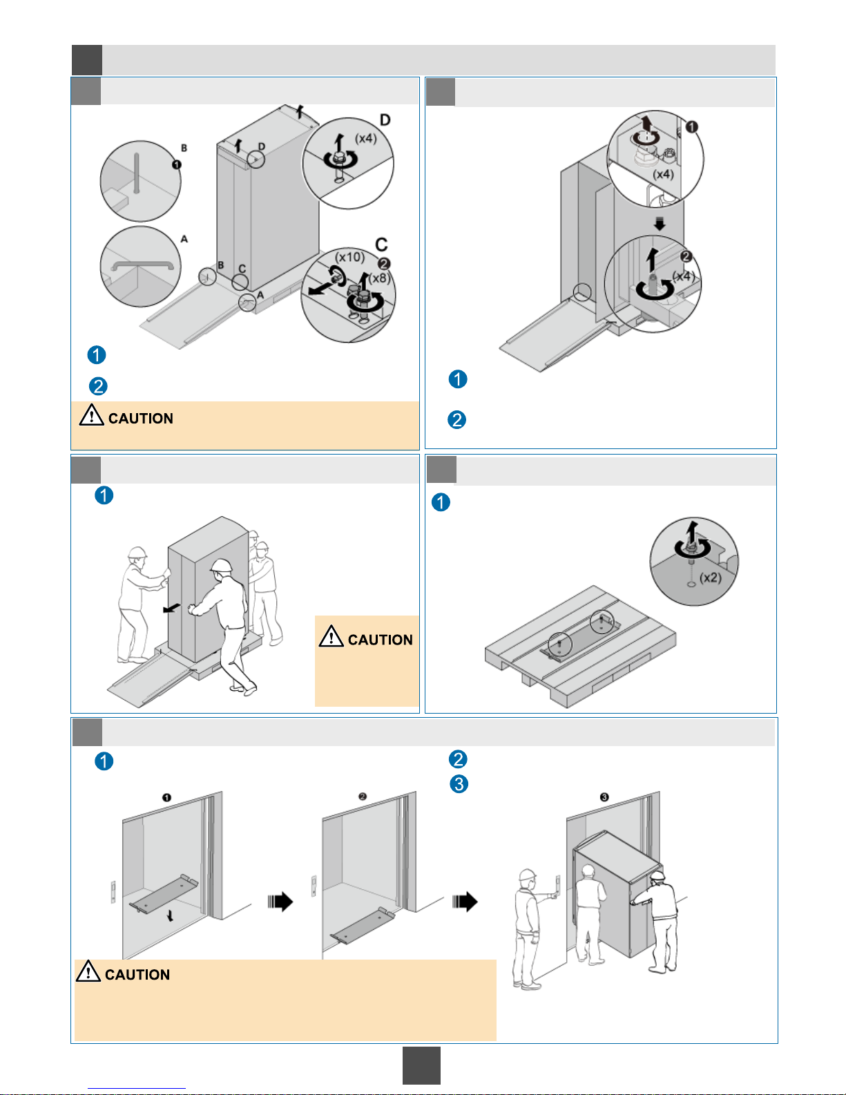
Moving the Cabinet (Moving the Cabinet with Devices Using Elevators)
2a
1
1 Secure the ramp in place.
1
2 Remove the screws from the cabinet.
1
3 Slide down the cabinet from the pallet.
1
4 Remove the shim from the pallet.
5 Move the cabinet into the elevator.
Use dowels to fix one end of the ramp on the pallet
and put the other end of the ramp on the ground.
Use an adjustable wrench to remove all screws from
the front and rear doors of the cabinet.
Do not place the ramp upside down.
Use an adjustable wrench to turn the four supporting
feet of the cabinet anticlockwise until the leveling
feet bear the whole cabinet weight.
Use an adjustable wrench to remove all screws from
the front and rear doors of the cabinet.
Push the cabinet. The wheeled cabinet can be
easily moved down from the pallet.
Two people are
required to move
the cabinet.
Use an adjustable wrench to remove the shim from
the pallet.
Place the shim on the gap of the elevator door.
Ensure that the shim is securely placed.
Push the cabinet into the elevator.
Ensure that the shim is firmly placed.
Ensure that the wheels of the cabinet move along the shim.
Use the same way to move the cabinet into and out of the elevator.
A dedicated person is required to open and close the elevator door.
Page 31
31
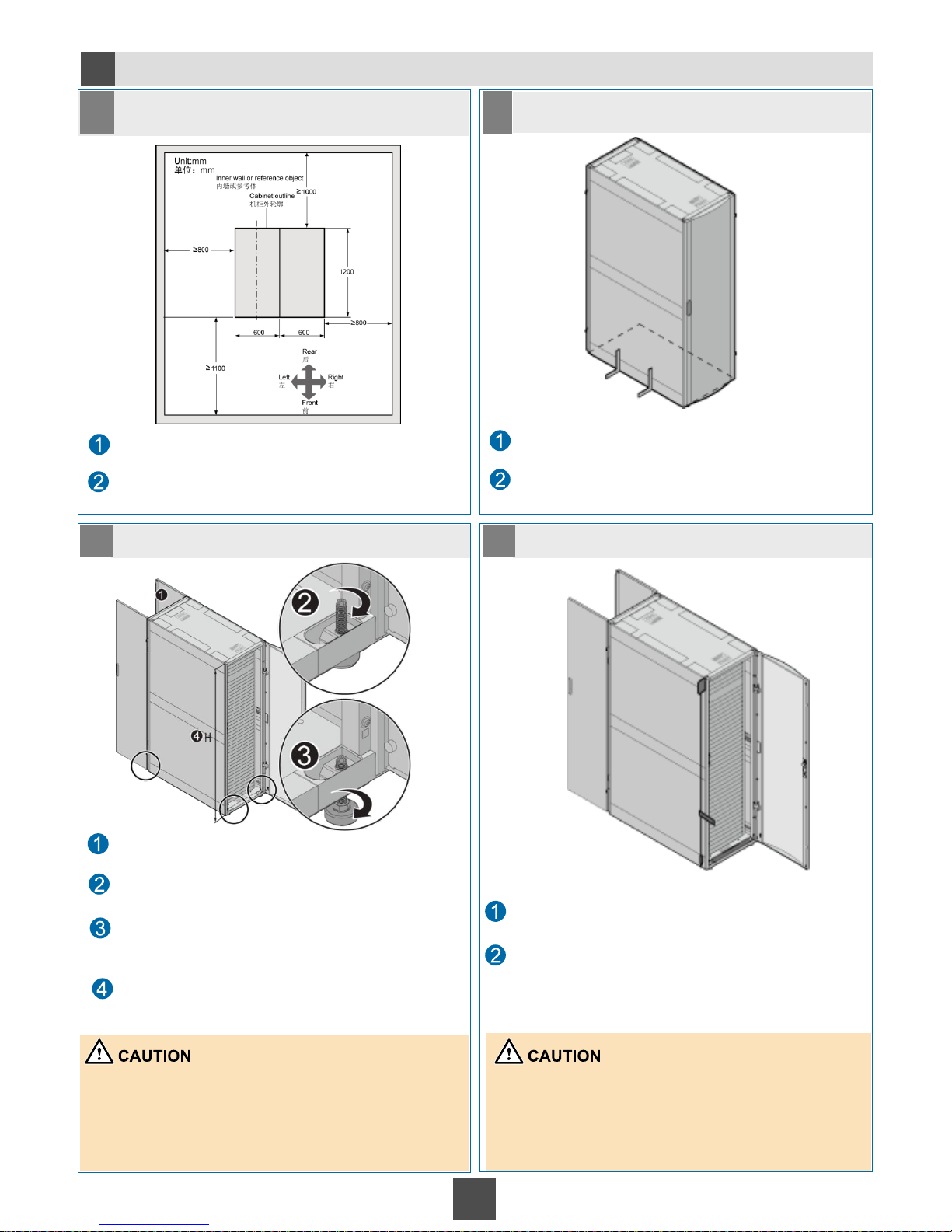
Installing the Cabinet
2b
1
1 Determine the installation position of the
cabinet.
1
2 Place the cabinet in place.
1
3 Secure the cabinet in place.
1
4 Level the cabinet.
Use the powder marker to draw the outline of the
cabinet.
Determine the position for installing the cabinet
based on the engineering drawing. Mark the four
corners of the cabinet
Move the cabinet in place.
Align the cabinet edges with the marks on the floor
using a right square.
Open the front and rear doors.
Rotate the four leveling feet clockwise by using a
Phillips screwdriver to lower the leveling feet.
Rotate the M12 bolts at the bottom of the leveling
feet clockwise by using an adjustable wrench until
the leveling feet contact the ground and the wheels
hang in the air.
Ensure that the heights measured from the front,
rear, right, and left of the cabinet are the same.
Spin the wheels by using a Phillips screwdriver. If the
wheels rotate freely, they are hanging in the air.
H indicates the distance from the cabinet top to the
ground. The cabinet height can be adjusted from 1195
mm to 1205 mm with the help of the leveling feet.
Use a level and plumb line to measure the cabinet.
Ensure that the cabinet is level.
If the cabinet is not level, use an adjustable wrench to
raise or lower the leveling feet.
Measure the front and rear doors of the cabinet as
follows:
Place the level along the surface of the cabinet. If
the air bubble goes to the center of the clear tube,
the surface is even.
Page 32
32
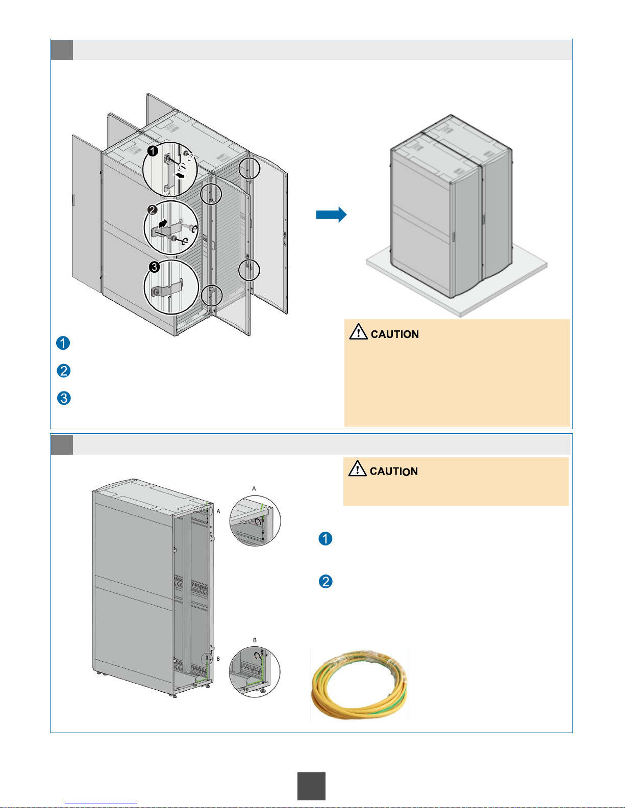
Connect the ground cable of the cabinet
to the ground bar of the equipment room.
Specifications: 25030190
electrical power cable - 450
V/750 V - 60227 IEC 02 (RV) 10 mm^2 - yellow/green - 62 A
Color: yellow-green
Obtaining method: auxiliary
material package
5 (Optional) Combine the cabinets.
6 Ground the cabinet.
Ground cable
of the cabinet
If two or more cabinets are required, these cabinets must be combined. Ignore this
operation if only one cabinet is required.
Unscrew the connecting plates on the front door
and rear doors using a Phillips screwdriver.
Pass the connecting plate through the gap on the
cabinet door and secure it using the screws
removed during step 1.
The figure on the right shows that the cabinets are
combined using connecting plates.
There are four connecting points on the front door
and rear door of the middle cabinets.
There are two connecting points on the front door
and rear door of the side cabinets.
Ensure that the vertical deviation and the
distance between cabinets are not greater than 3
mm after the cabinets are combined.
Route the cabinet ground cable from position A
to the upper cable outlet or from position B to
the bottom cable outlet.
This operation must be performed by professional
electricians onsite.
Page 33
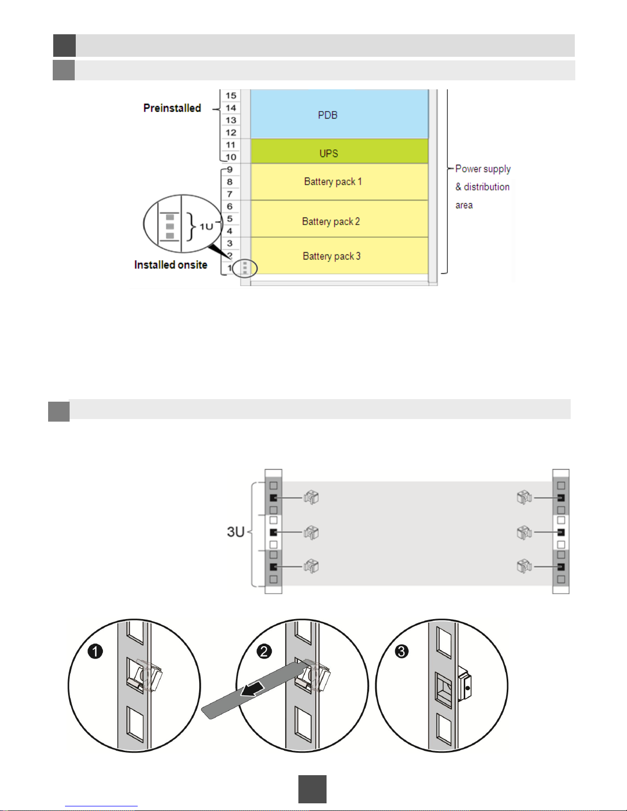
Installing Battery Packs
2c
33
Due to the limited length of cables, observe the following when installing battery packs:
Install battery packs in the following sequence: 7–9 U, 4–6 U, and 1–3 U.
• If only one battery pack is required, place it in the position of battery pack 1.
• If two battery packs are required, place them in the positions of battery pack 1 and battery pack
1 Determine installation positions.
Use the floating nut installation bar to install the floating nuts on the tapped hole of the mounting bar
inside the cabinet.
The figure on the right shows the
positions of the floating nuts.
Installation method:
2
Install floating nuts.
Installation position of
battery packs
Page 34
34
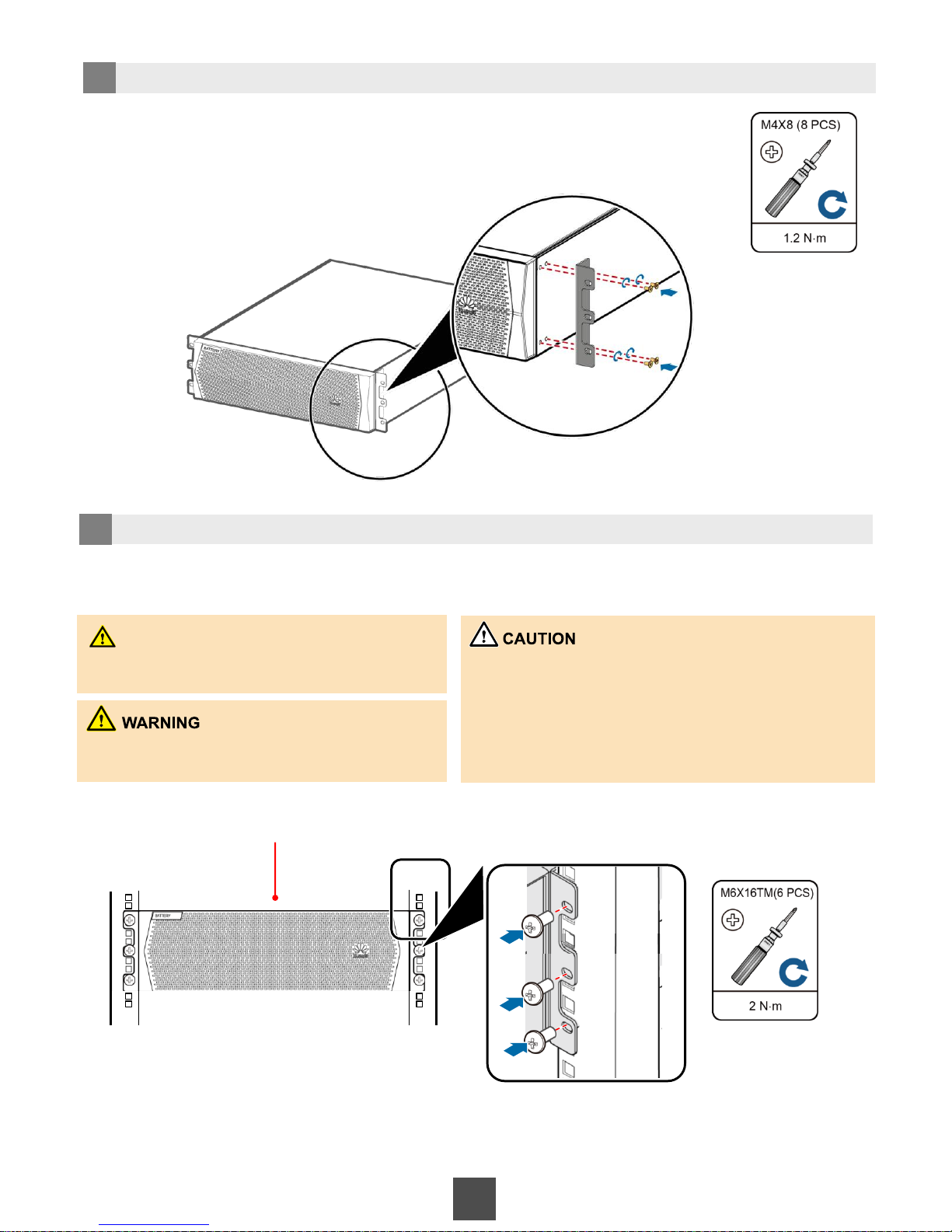
3 Install mounting ears.
Place the battery pack on the guide rails, and insert the M6 x 16TM screws into the mounting holes to secure
the battery pack to the rack.
Battery pack
1. Moving battery packs using mounting ears, front panels,
and wiring terminal covers is prohibited.
When moving heavy objects, follow the standardized
operation.
2. When moving battery packs, take off metal ornaments,
such as watches and rings.
DANGER
The rack must be grounded before you perform
this operation.
Do not touch non-insulated battery wiring
terminals.
4 Install battery packs in the rack.
Page 35
35
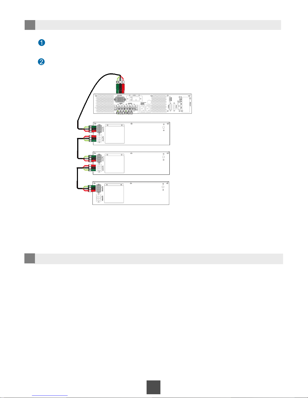
5 Connect the UPS with battery packs.
UPS
Battery pack 1
Battery pack 2
Battery pack 3
Remove the dust-proof protective iron plates from the ports on
the UPS and battery packs using a Phillips screwdriver.
Connect the UPS and battery packs and secure the connectors using a
screwdriver, as shown in the following figure.
6 Install filler panels.
After installing all battery packs on the shelf in the cabinet and connecting cables
to them, install filler panels on each battery pack.
Page 36
2d
Installing the Server (The RH2285 is used as an example.)
36
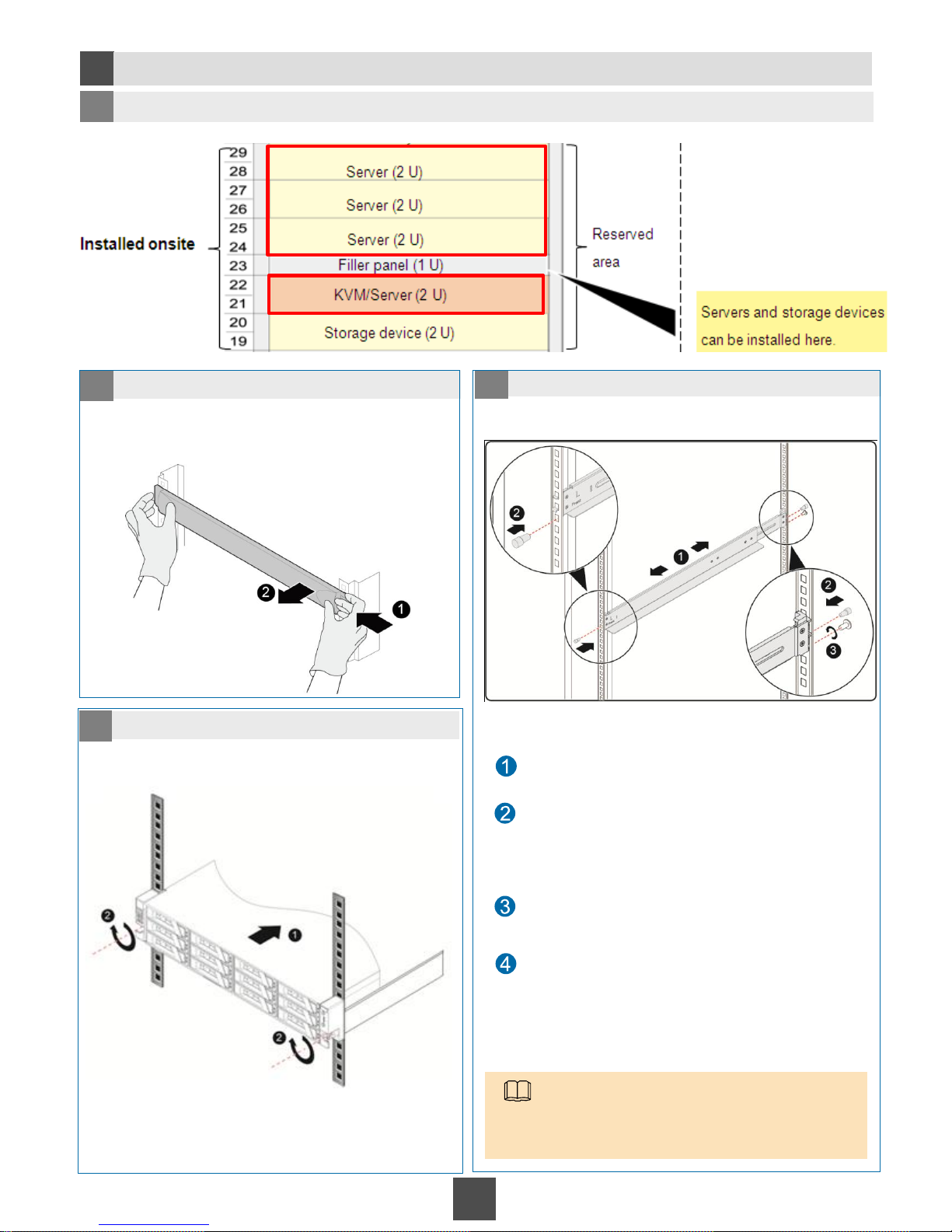
1 Determine the installation position.
2 Remove the filler panel. 3 Install guide rails.
4 Install the server in the rack.
Hold one side of the filler panel with one hand, and
hold the buckle on the other side of the filler panel
with the other hand, press the buckle with the middle
finger, and pull out the filler panel with proper force.
Place the guide rail horizontally at the planned
position near the rack installation bar and hook the
buckle.
Insert an M6 screw to the first square hole at the rear
of the guide rail and fasten the M6 screw.
Use the same method to install the guide rail on the
other side of the server.
Insert the rubber plugs delivered with the guide rails
into the following square holes to fasten the guide
rails:
•Square hole at the front bottom of the guide rail
•Square hole in the rear middle of the guide rail
NOTE
Guide rails are preinstalled at the 20 U to 21 U
height before delivery. You only need to install
guide rails at 22 U to 29 U.
Page 37
37
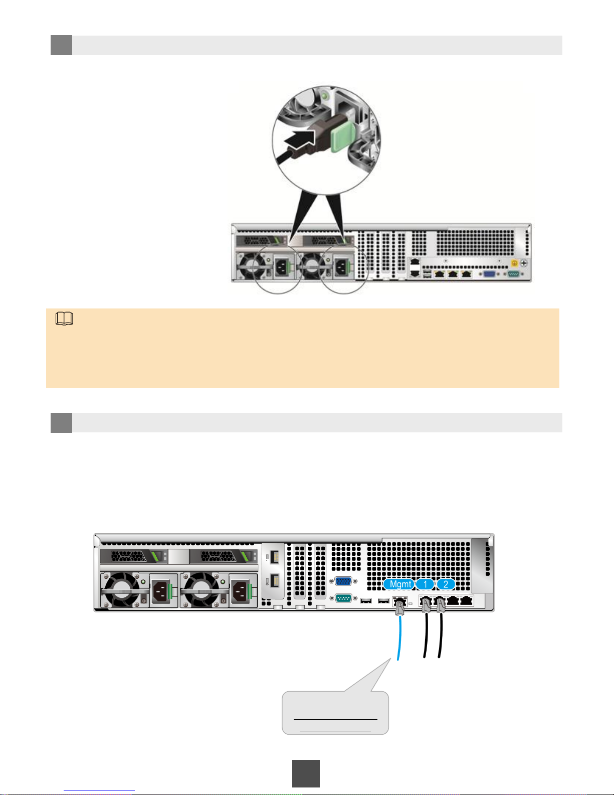
5 Connect power cables.
6 Connect the switch and the server.
Find the network cables from the switch based on the labels and connect the network cables to the
corresponding ports on the server.
NOTE
Connect the two reserved power cable connectors on the PDU to the server based on labels. Make sure that
the installation position on the label is the same as the server.
No ground cable is required because the RH2285 is configured with AC power modules.
RH2285H
#5
21/22U-Server-1-M
37U-S5700-G05
Lable example:
Page 38
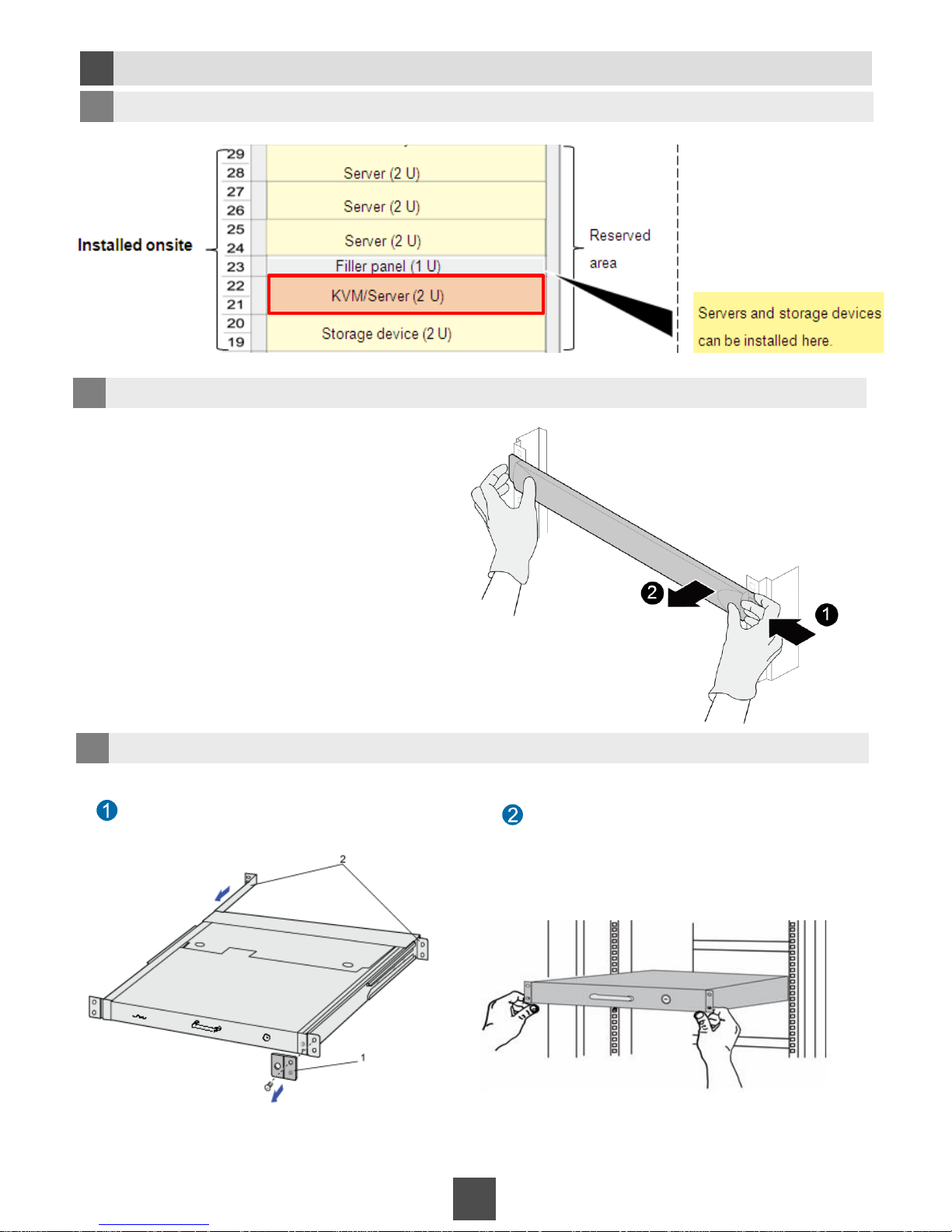
2e
Installing the KVM
38
1 Determine the installation position.
2 Remove the filler panel.
3 Install the KVM.
Hold one side of the filler panel with one
hand, and hold the buckle on the other side
of the filler panel with the other hand, press
the buckle with the middle finger, and pull
out the filler panel with proper force.
Remove the shipping bracket from the KVM
front panel.
Put the KVM on the guide rails through the
front of the cabinet as planned and slide it
to the right position.
Page 39
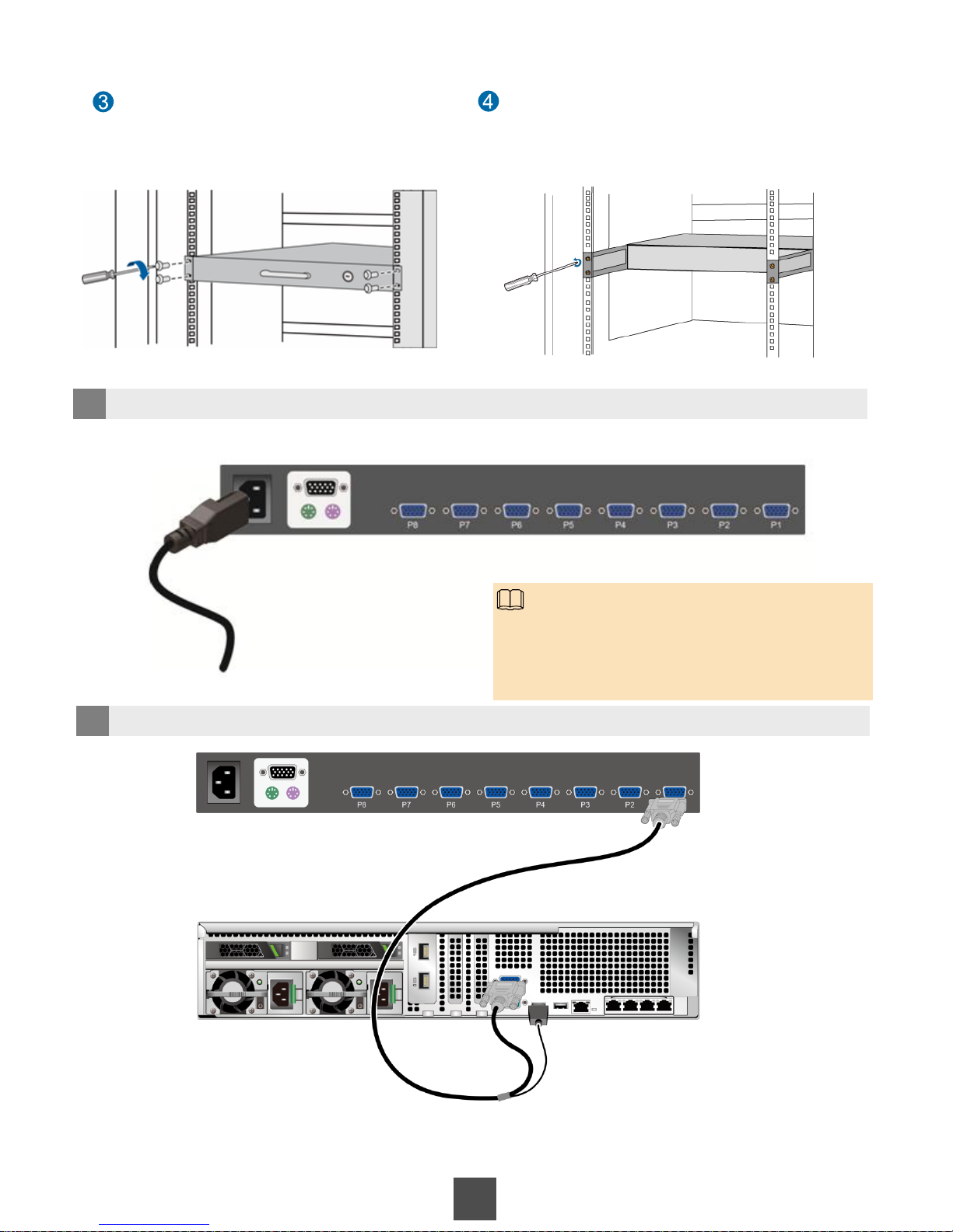
39
Use screws to fasten the front mounting
ears of the KVM to the mounting bars of
the cabinet.
Insert rear mounting ears to the rear
mounting ear conduits, and use screws to
secure the rear mounting ears to the
mounting bars of the cabinet.
4 Connect the KVM to the PDU.
5 Connect the KVM to servers.
Servers in the rack are connected to the eight KVM ports (numbered from P1 to P8) from
the bottom up to facilitate subsequent maintenance.
NOTE
Connect the reserved power cable connector on the
PDU to the KVM. No ground cable is required because
the KVM is configured with AC power modules.
Page 40
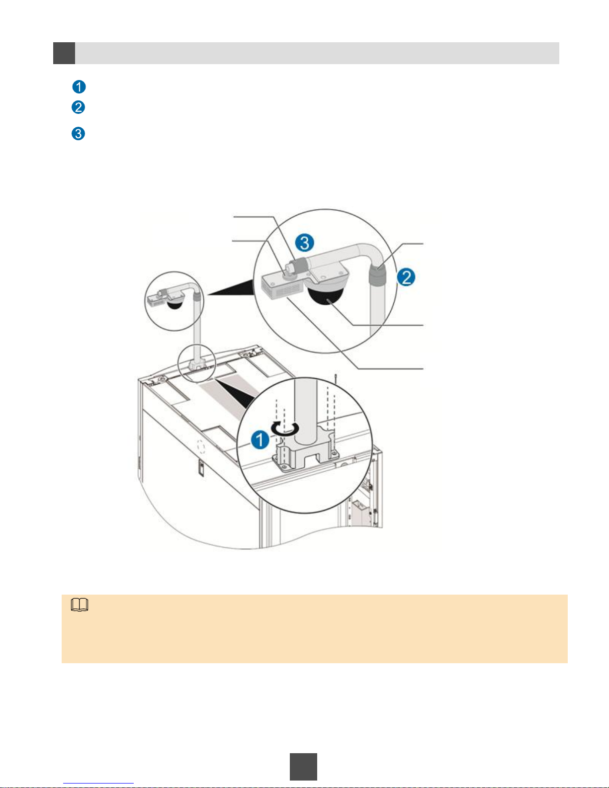
40
Securing the Integrated Sensor Mounting Arm
2f
Secure the integrated sensor mounting arm using the M5 Phillips screwdriver.
Rotate tube 1 to adjust the sensor mounting arm.
Adjust the angles of the smoke sensor and the camera using the rotatable connector, and secure the rotatable tube 2.
Tube 1
Tube 2
Camera
Smoke sensor
Adjustable connector
NOTE
• Two people are required to install the integrated sensor mounting arm with the help of a step ladder.
• Use an M5 Phillips screwdriver to secure self-tapping screws for the integrated sensor mounting arm base.
• Rotate tube 1 to adjust the sensor mounting arm until it is in the highest position. Then adjust the camera based
on the object to be monitored.
Page 41
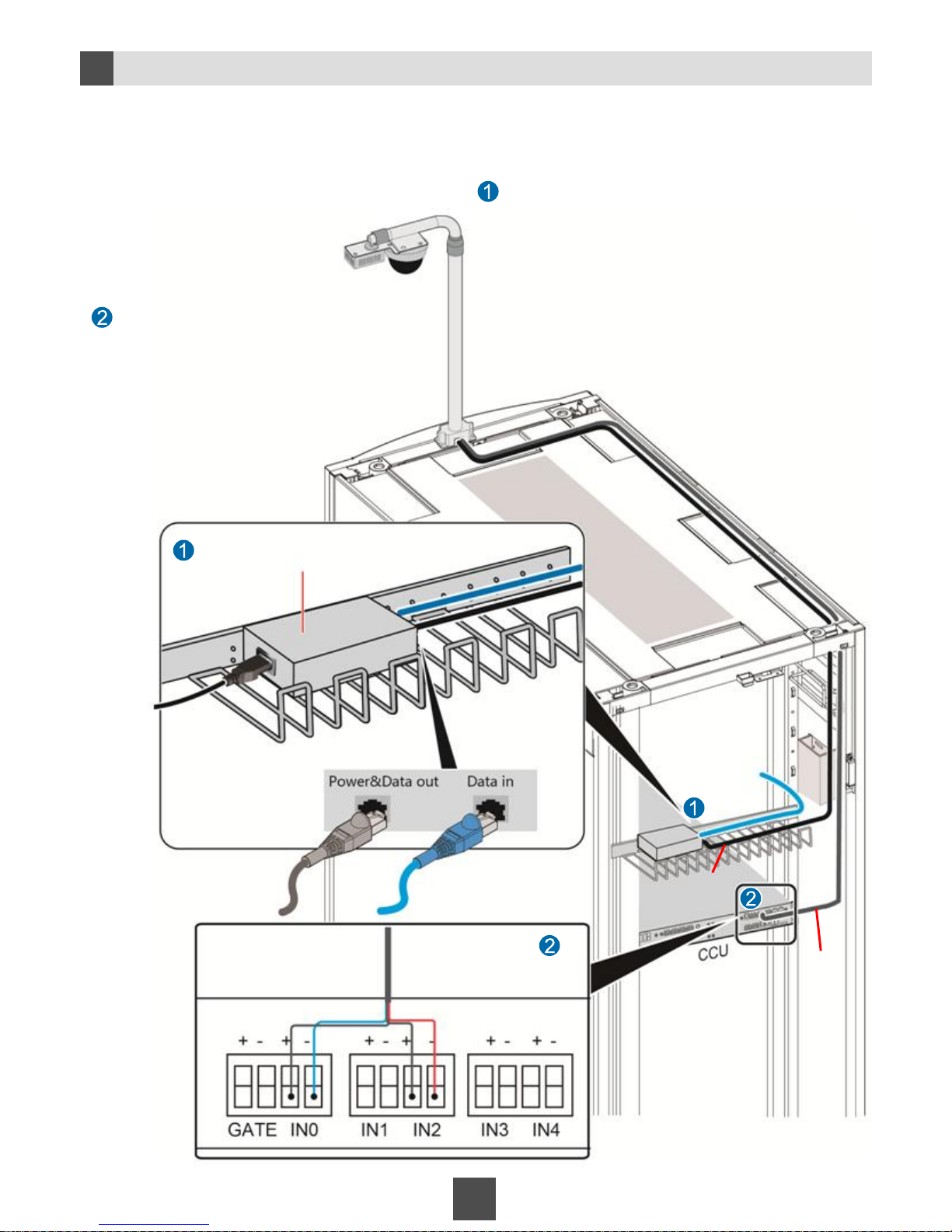
2g
Connecting Cables to the Camera
41
Connect the signal cables to the ports
on the CCU according to the labels on
the signal cables.
• The sensor mounting arm provides a network cable and a signal cable.
• The signal cable provides two camera signal cables and two smoke sensor signal cables.
• Connect the camera network cable to the PoE power adapter, and connect the camera single cables to
the CCU.
1. Place the PoE power adapter on the 17 U cable rack at the
rear of the cabinet.
2. Insert the reserved PDU power plug near the cable rack to
the power adapter.
3. Connect the network cable of the camera to the
Power&Data out port on the PoE power adapter.
4. Connect the network cable reserved for the switch near
the cable rack to the Data in port.
5. Secure the PoE power adapter using cable ties.
Connect the network cable to the camera.
Connect the signal cables to the camera.
CCU rear view
Camera signal cables
(camera)
Smoke sensor signal
cables(smoke)
Network cable
reserved for the
switch
Camera
network cable
PoE power adapter
Camera signal
cables
Page 42
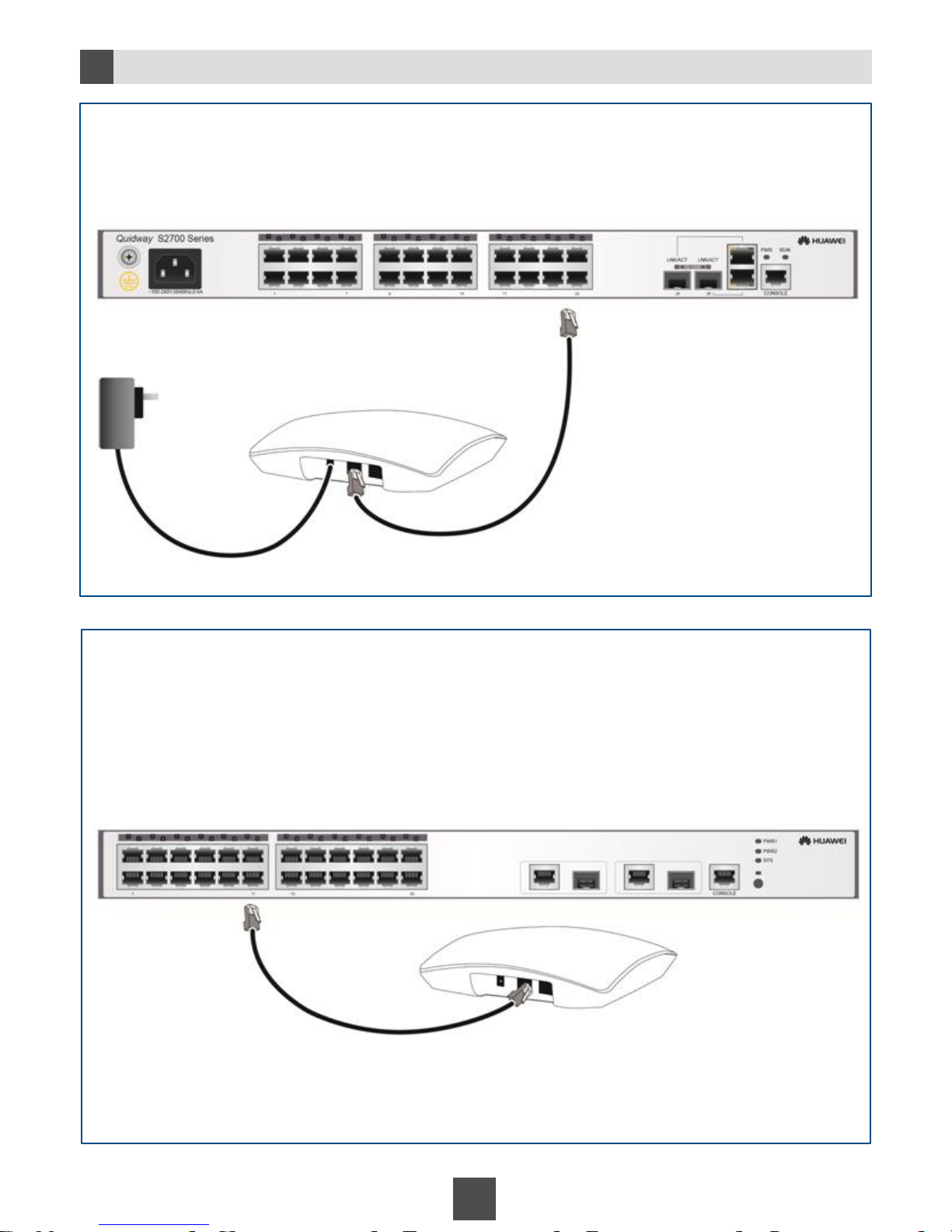
2h
Installing the AP
42
Scenario 1 AP with a power adapter
The AP obtains power using the power adapter.
Scenario 2 AP without a power adapter
The AP is connected to a switch with PoE function.
The AP obtains power by connecting to a network cable.
Connect the AP to the switch based on the network plan.
Connect the AP to the switch with the PoE function
based on the network plan.
Network cable
Power
adapter
Connecting the power
adapter to a mains power
socket
Switch
Network cable
PoE switch
Page 43
43
3 Inspecting Devices Before Power-On
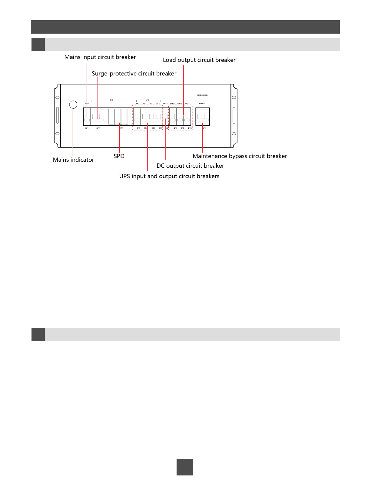
Checking the PDB
3a
Testing mechanical performance
1.Switch on and off all circuit breakers three times. Ensure that they can be switched on and off
smoothly.
2.Check that all bolts are secured for cables. Fasten the bolts that are not properly secured.
3.Check that screws at the ground point are secured. Fasten the screws that are not properly
secured.
Testing insulation performance
(You are advised to test the insulation performance together with the onsite electricians.)
1. Switch off the surge-protective circuit breaker (QF2).
2. Check that the insulation resistance between the L terminal and the PE terminal on the PDB
is greater than or equal to 2 MΩ.
3. Check that the insulation resistance between the N terminal and the PE terminal on the PDB
is greater than or equal to 2 MΩ.
Checking the UPS
3b
1. Switch on and off all input circuit breakers three times. Ensure that they can be
switched on and off smoothly.
2. Check that all bolts are secured for cables. Fasten the bolts that are not properly
secured.
3. Check that the voltage between the mains input neutral wire and the ground cable
is less than 5 V AC. (You are advised to test the insulation performance together
with the onsite electricians.)
Page 44
44
1. Check that all bolts are secured for cables. Fasten the bolts that are not properly
secured.
2. Check that the voltage between the positive and negative terminals is greater than
192 V DC. (You are advised to test the insulation performance together with the
onsite electricians.)
3. Check that screws at the ground points of the battery packs are secured.
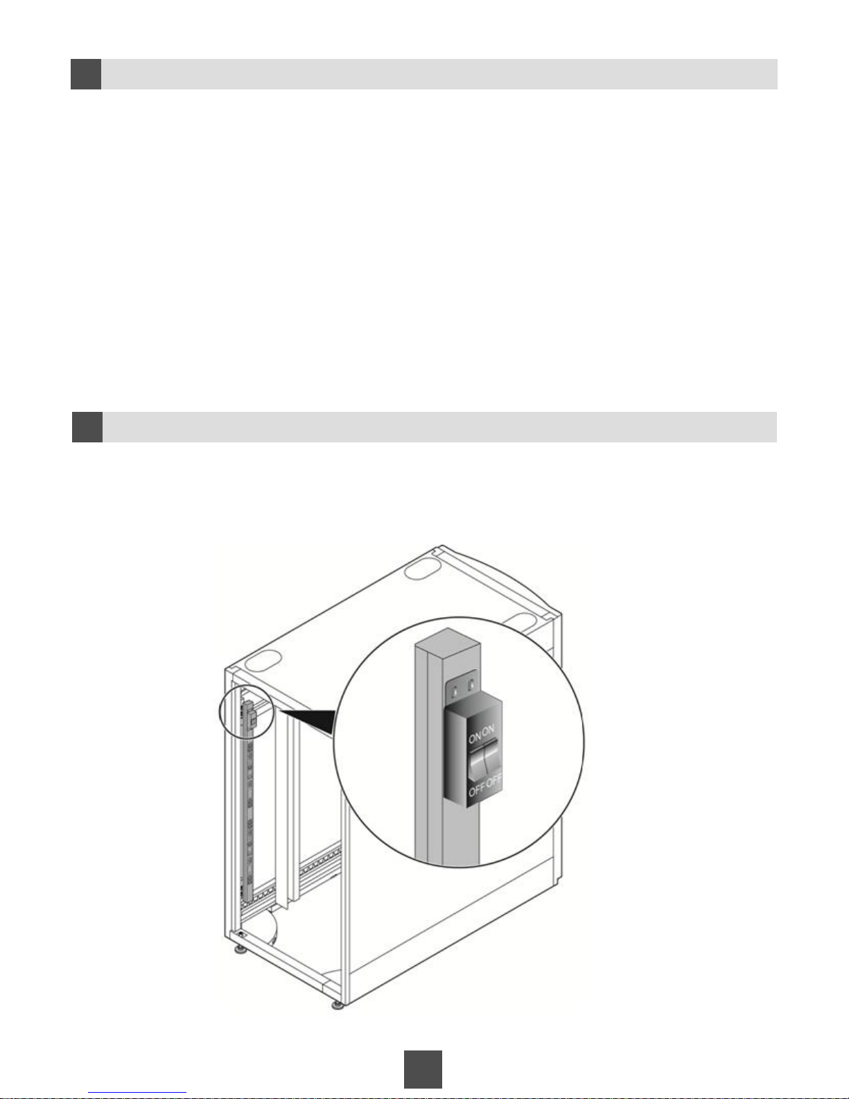
1. Switch on and off all circuit breakers three times. Ensure that they can be switched on and
off smoothly.
2. Check that all bolts are secured for cables. Fasten the bolts that are not properly secured.
3c
Commissioning Battery Packs
Checking the PDU
3d
Page 45
45
4 Performing Power-On and Power-Off Commissioning
Connecting the Power Cable of the Cabinet
4a
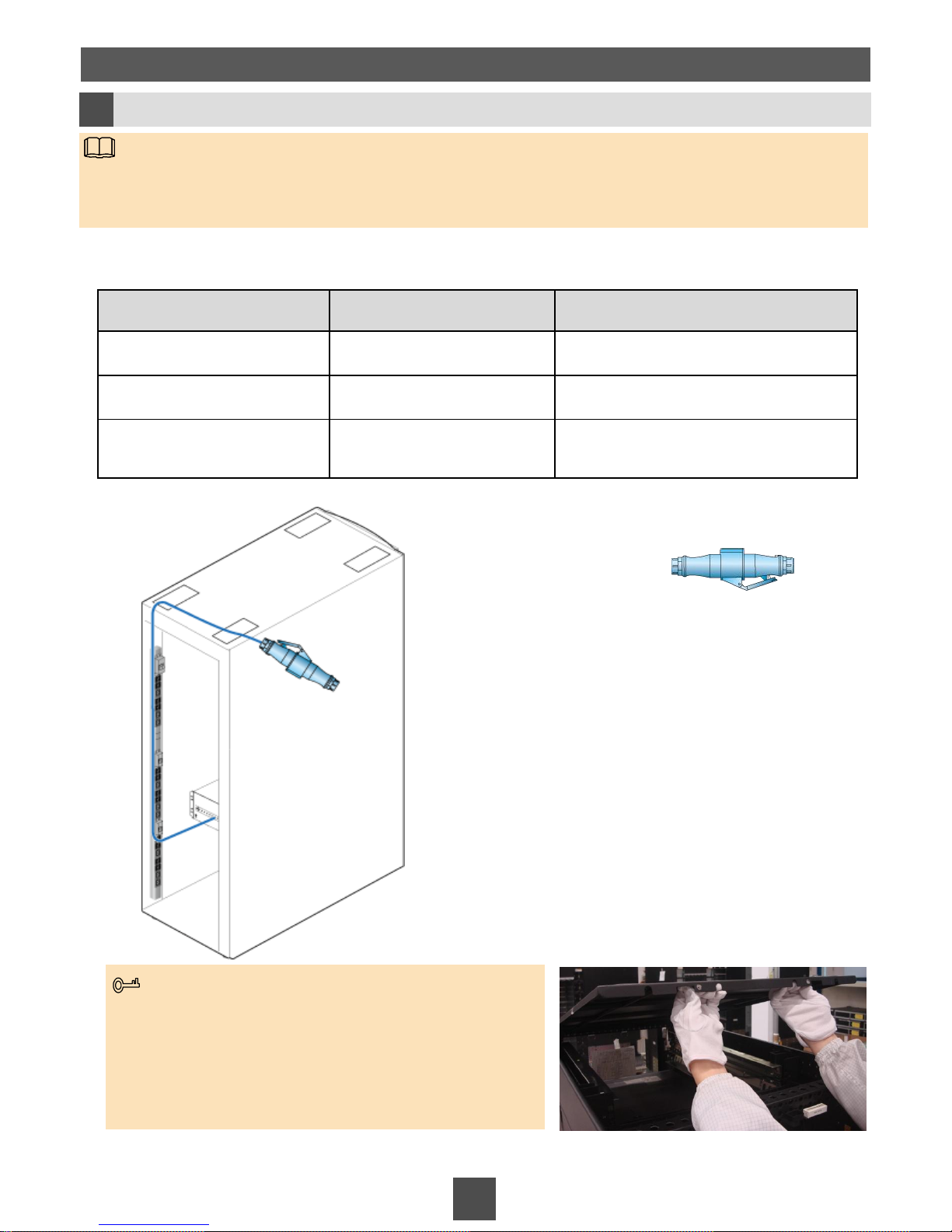
Industrial connector
• The 42 U cabinet connects to the mains supply cable through an industrial connector.
• The mains supply cable is prepared by customers based on the electrical specifications of
the external mains power distribution system.
NOTE
Parameter Value Remarks
Input voltage
176 V to 264 V AC
Maximum input current
32 A
Input circuit breaker
32 A/1 P Connect with an industrial connector
complying with IEC standards.
Electrical specifications for the external mains power distribution system
Connect to the mains
power system
If the industrial connector fails to route through the cable hole
at the top of the cabinet, pull the two positioning pins at the top
of the cabinet inwards simultaneously with both hands to raise
the cabinet cover.
After routing the industrial connector through the cable hole,
pull the positioning pins inwards again with both hands to close
the cabinet cover. Then release your hands to secure the pins.
Tips
Page 46
46
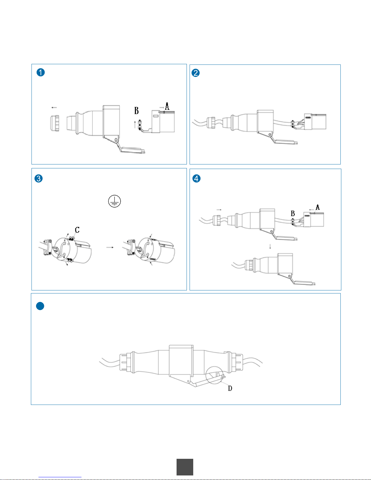
5
B
Remove screw C, insert the live wire (brown),
neutral line (blue), and ground cables (yellow
and green) into the screw-type terminals that
are labeled L, N, and respectively, and
fasten screw C.
Loosen component 1 and screw A, remove
component 3, and loosen screw B.
Pass the cable through component 1 and
component 2 to the pressing sheet of
component 3 (at the position of screw B).
Fasten screw B to secure the cables, fix
component 3 into component 2, and fasten
screw A and component 1.
Connect the industrial connector to the industrial socket until the industrial connector is firmly
seated in the slot at the middle of the industrial socket (at the position of D as shown in the figure
on the right).
Component 1 Component 2
Component 3
Installing the industrial connector
(This operation must be performed by professional electricians onsite.)
Page 47
47
4b
Performing Power-On and Power-Off Commissioning
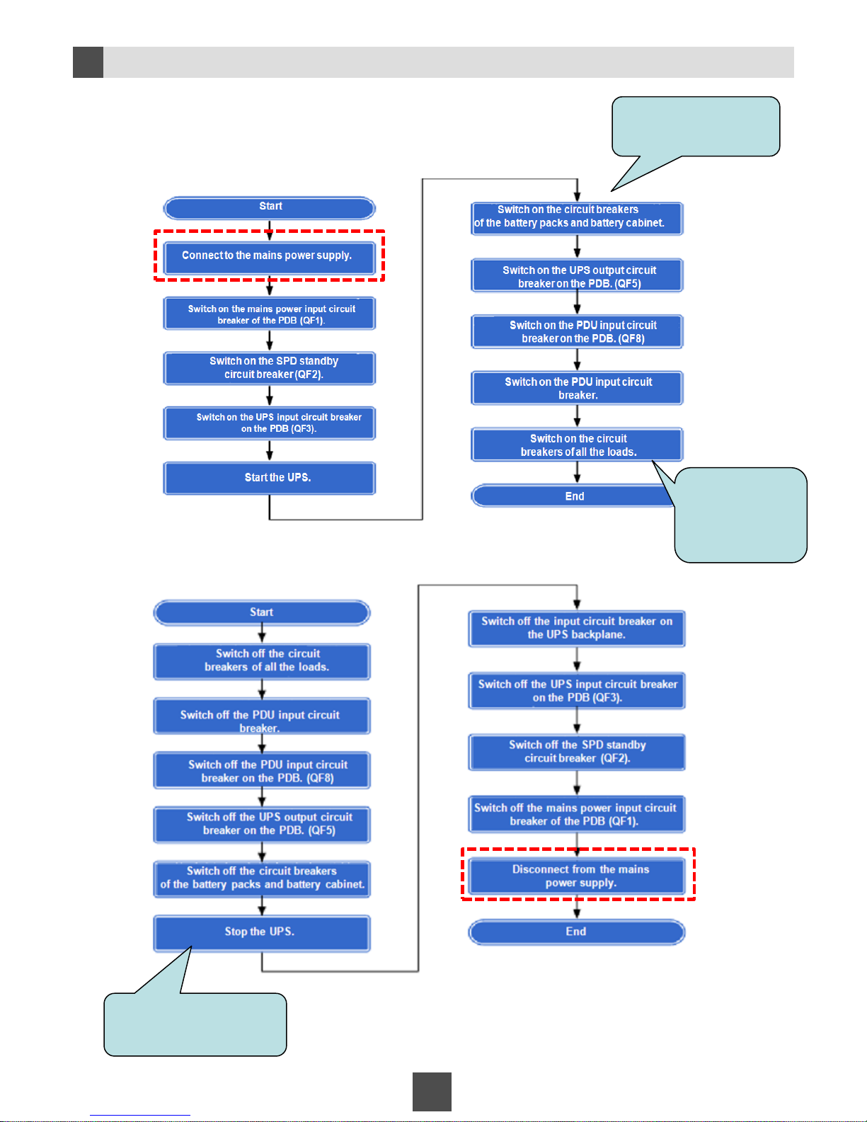
Power-on process
Power-off process
Onsite
environment
Onsite
environment
The hardware installation of the MicroDC3000H suite is
complete. For subsequent operations, see Appendix.
For details, see Starting
and Stopping the UPS
in Appendix B. P49
Loads refer to
power consuming
devices, such as
switches and
routers.
For details, see Starting
and Stopping the UPS
in Appendix B. P49
Page 48

Appendix
48
A
Subsequent Operations
MicroDC System Commissioning
For details about how to commission the MicroDC system, see the MicroDC V100R001C20
Commissioning Guide.
You can obtain the MicroDC V100R001C20 Commissioning Guide from:
• DVD-ROM delivered with the MicroDC V100R001C20 cabinet
• http://enterprise.huawei.com
(Product Support > Cloud Computing & Data Centers > Data Center > MicroDC > MicroDC)
Hardware Commissioning
For details about how to commission the hardware, see the MicroDC V100R001C20 Commissioning
Guide.
You can obtain the MicroDC V100R001C20 Commissioning Guide from the DVD-ROM delivered with the
MicroDC V100R001C20 cabinet or at http://enterprise.huawei.com.
(Product Support > Cloud Computing & Data Centers > Data Center > MicroDC > MicroDC)
Rapid Deployment
1. Install the MySQL database.
2. Install the rapid deployment tool.
3. Log in to the rapid deployment tool and perform rapid deployment.
For details, see the MicroDC V100R001C20 Rapid Deployment Guide.
You can obtain the MicroDC V100R001C20 Rapid Deployment Guide from:
• DVD-ROM delivered with the MicroDC V100R001C20 cabinet
• http://enterprise.huawei.com
(Product Support > Cloud Computing & Data Centers > Data Center > MicroDC > MicroDC)
eSight Commissioning
For details, see the MicroDC V100R001C20 Commissioning Guide.
You can obtain the MicroDC V100R001C20 Commissioning Guide from:
• DVD-ROM delivered with the MicroDC V100R001C20 cabinet
• http://enterprise.huawei.com
(Product Support > Cloud Computing & Data Centers > Data Center > MicroDC > MicroDC)
Page 49
49
B
Starting and Stopping the UPS
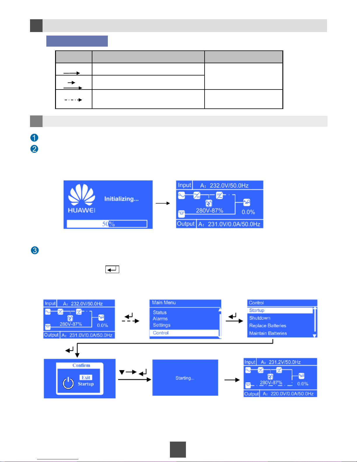
Switch off the AC input circuit breaker on the UPS backplane. The screen for initializing the UPS is displayed.
Go to the main screen.
When the progress bar on the initializing screen reaches 100%, the UPS main screen is displayed. The UPS
enters the bypass mode with buzzes.
Symbol Description Remarks
Choose A. A and B indicate the operators
on the UPS control panel.
Choose A and then B.
Some screens are omitted between the two
screens at both ends of the sign.
None
A
A B
Symbol description
1 Starting the UPS
Start the UPS
On the main screen, press to go to the main menu. Choose Control > Startup to start the UPS.
The UPS works in normal mode, with the buzzes stopped.
Page 50
50
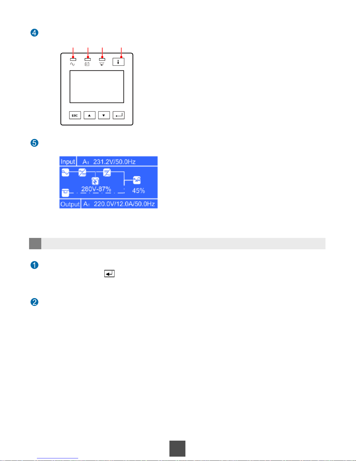
After the UPS is running properly, start the loads.
Switch the UPS from the normal mode to the bypass mode.
On the main screen, press on the UPS panel to go to the main menu and choose Shutdown. The UPS switches to
the bypass mode with buzzes.
Switch off all the switches on the UPS backplane.
The UPS stops buzzing. If all the indicators are off and the fans stops running, the UPS stops.
2 Stopping the UPS
Observe the indicators on the UPS panel. If the indicators 1 and 4 are steady green, the UPS starts properly.
1 2 3 4
 Loading...