

Page 1

HUAWEI ME909u-521 LTE LGA Module
Application Guide
Issue
01
Date
2013-07-05
Page 2

Huawei Technologies Co., Ltd. provides customers with comprehensive technical support and service. For
any assistance, please contact our local office or company headquarters.
Huawei Technologies Co., Ltd.
Huawei Industrial Base, Bantian, Longgang, Shenzhen 518129, People’s Republic of China
Tel: +86-755-28780808 Global Hotline: +86-755-28560808 Website: www.huawei.com
E-mail: mobile@huawei.com
Please refer color and shape to product. Huawei reserves the right to make changes or improvements to any
of the products without prior notice.
Copyright © Huawei Technologies Co., Ltd. 2013. All rights reserved.
No part of this document may be reproduced or transmitted in any form or by any means without prior written
consent of Huawei Technologies Co., Ltd.
The product described in this manual may include copyrighted software of Huawei Technologies Co., Ltd and
possible licensors. Customers shall not in any manner reproduce, distribute, modify, decompile, disassemble,
decrypt, extract, reverse engineer, lease, assign, or sublicense the said software, unless such restrictions
are prohibited by applicable laws or such actions are approved by respective copyright holders under
licenses.
Trademarks and Permissions
, , and
Other trademarks, product, service and company names mentioned are the property of their respective
owners.
are trademarks or registered trademarks of Huawei Technologies Co., Ltd.
Notice
Some features of the product and its accessories described herein rely on the software installed, capacities
and settings of local network, and may not be activated or may be limited by local network operators or
network service providers, thus the descriptions herein may not exactly match the product or its accessories
you purchase.
Huawei Technologies Co., Ltd reserves the right to change or modify any information or specifications
contained in this manual without prior notice or obligation.
NO WARRANTY
THE CONTENTS OF THIS MANUAL ARE PROVIDED "AS IS". EXCEPT AS REQUIRED BY APPLICABLE
LAWS, NO WARRANTIES OF ANY KIND, EITHER EXPRESS OR IMPLIED, INCLUDING BUT NOT
LIMITED TO, THE IMPLIED WARRANTIES OF MERCHANTABILITY AND FITNESS FOR A PARTICULAR
PURPOSE, ARE MADE IN RELATION TO THE ACCURACY, RELIABILITY OR CONTENTS OF THIS
MANUAL.
TO THE MAXIMUM EXTENT PERMITTED BY APPLICABLE LAW, IN NO CASE SHALL HUAWEI
TECHNOLOGIES CO., LTD BE LIABLE FOR ANY SPECIAL, INCIDENTAL, INDIRECT, OR
CONSEQUENTIAL DAMAGES, OR LOST PROFITS, BUSINESS, REVENUE, DATA, GOODWILL OR
ANTICIPATED SAVINGS.
Import and Export Regulations
Customers shall comply with all applicable export or import laws and regulations and will obtain all necessary
governmental permits and licenses in order to export, re-export or import the product mentioned in this
manual including the software and technical data therein.
Page 3
HUAWEI ME909u-521 LTE LGA Module
Application Guide
About This Document
Issue 01 (2013-07-05)
Huawei Proprietary and Confidential
Copyright © Huawei Technologies Co., Ltd.
3
Revision History
Document
Version
Date
Chapter
Description
01
2013-07-05
Creation
About This Document
Page 4

HUAWEI ME909u-521 LTE LGA Module
Application Guide
Contents
Issue 01 (2013-07-05)
Huawei Proprietary and Confidential
Copyright © Huawei Technologies Co., Ltd.
4
Contents
1 Overview ......................................................................................................................................... 7
1.1 Conventions and Definitions ............................................................................................................ 7
1.1.1 Conventions ............................................................................................................................. 7
1.1.2 Definitions ................................................................................................................................ 7
1.2 Organization of This Document ........................................................................................................ 8
1.3 Basic AT Command Processing Principles ...................................................................................... 9
1.3.1 Ports ........................................................................................................................................ 9
1.3.2 AT Command Processing Mechanism..................................................................................... 9
1.3.3 Recommended Timeout Mechanism for AT Commands Processed by a Host..................... 12
2 Initialization Application Scenarios ....................................................................................... 14
2.1 Startup Indication ^SYSSTART ...................................................................................................... 14
2.1.1 Reference Process ................................................................................................................ 14
2.1.2 Troubleshooting ..................................................................................................................... 14
2.2 Querying Basic Information ............................................................................................................ 15
2.2.1 Reference Process ................................................................................................................ 15
2.2.2 Troubleshooting ..................................................................................................................... 15
2.3 Network Service Operations .......................................................................................................... 16
2.3.1 Reference Process ................................................................................................................ 16
2.3.2 Troubleshooting ..................................................................................................................... 17
3 Network Searching and Registration Application Scenarios............................................. 18
3.1 Searching and Registering Network............................................................................................... 18
3.1.1 Reference Process ................................................................................................................ 18
3.1.2 Troubleshooting ..................................................................................................................... 20
4 ECM Application Scenarios ...................................................................................................... 21
4.1 ECM Dialing ................................................................................................................................... 21
4.1.1 Reference Process ................................................................................................................ 21
4.1.2 Troubleshooting ..................................................................................................................... 22
4.2 Querying the Dial-up Connection State .......................................................................................... 22
4.2.1 Reference Process ................................................................................................................ 22
4.2.2 Troubleshooting ..................................................................................................................... 23
4.3 Disconnecting the Dial-up Connection ........................................................................................... 23
4.3.1 Reference Process ................................................................................................................ 23
Page 5

HUAWEI ME909u-521 LTE LGA Module
Application Guide
Contents
Issue 01 (2013-07-05)
Huawei Proprietary and Confidential
Copyright © Huawei Technologies Co., Ltd.
5
4.3.2 Troubleshooting ..................................................................................................................... 23
5 SMS Application Scenarios ...................................................................................................... 24
5.1 Overview ........................................................................................................................................ 24
5.2 Initializing SMS ............................................................................................................................... 26
5.2.1 Reference Process ................................................................................................................ 26
5.2.2 Troubleshooting ..................................................................................................................... 29
5.3 Sending Short Message ................................................................................................................. 29
5.3.1 Reference Process ................................................................................................................ 29
5.3.2 Troubleshooting ..................................................................................................................... 31
5.4 Reading Short Messages ............................................................................................................... 32
5.4.1 Reference Process ................................................................................................................ 32
5.4.2 Troubleshooting ..................................................................................................................... 34
5.5 Deleting Short Messages ............................................................................................................... 34
5.5.1 Reference Process ................................................................................................................ 34
5.5.2 Troubleshooting ..................................................................................................................... 35
6 Phonebook Application Scenarios .......................................................................................... 36
6.1 Overview ........................................................................................................................................ 36
6.2 Memory Operations ........................................................................................................................ 36
6.2.1 Reference Process ................................................................................................................ 36
6.2.2 Troubleshooting ..................................................................................................................... 37
6.3 Reading Phonebook Entries .......................................................................................................... 38
6.3.1 Reference Process ................................................................................................................ 38
6.3.2 Troubleshooting ..................................................................................................................... 39
6.3.3 Writing/Deleting Phonebook Entries ...................................................................................... 40
6.3.4 Reference Process ................................................................................................................ 40
6.3.5 Troubleshooting ..................................................................................................................... 41
6.4 Searching for Phonebook Entries .................................................................................................. 42
6.4.1 Reference Process ................................................................................................................ 42
6.4.2 Troubleshooting ..................................................................................................................... 43
6.5 Querying User Number .................................................................................................................. 43
6.5.1 Reference Process ................................................................................................................ 43
6.5.2 Troubleshooting ..................................................................................................................... 44
6.6 Setting the TE's Character Sets ..................................................................................................... 44
6.6.1 Reference Process ................................................................................................................ 44
6.6.2 Troubleshooting ..................................................................................................................... 45
7 SIM Operation Application Scenarios .................................................................................... 46
7.1 PIN Operations ............................................................................................................................... 46
7.1.1 Reference Process ................................................................................................................ 46
7.1.2 Troubleshooting ..................................................................................................................... 47
7.2 CRSM Command ........................................................................................................................... 48
7.2.1 Reference Process ................................................................................................................ 48
Page 6

HUAWEI ME909u-521 LTE LGA Module
Application Guide
Contents
Issue 01 (2013-07-05)
Huawei Proprietary and Confidential
Copyright © Huawei Technologies Co., Ltd.
6
7.2.2 Troubleshooting ..................................................................................................................... 50
8 Sleeping and Waking Up Application Scenarios ................................................................. 51
8.1 Hardware Interfaces ....................................................................................................................... 52
8.2 Sequence Diagram......................................................................................................................... 53
8.3 Software Interfaces ........................................................................................................................ 54
8.3.1 Principle ................................................................................................................................. 54
8.3.2 USB and Sleep ...................................................................................................................... 56
8.3.3 UART and Sleep .................................................................................................................... 57
8.3.4 Module Wake-up .................................................................................................................... 57
8.3.5 Host Woken up by Module .................................................................................................... 57
8.4 Application Scenarios: System with USB Connection only ............................................................ 59
8.4.1 Hardware Connection ............................................................................................................ 59
8.4.2 Software Procedure ............................................................................................................... 59
8.4.3 Advantages ............................................................................................................................ 60
8.5 Application Scenarios: System with USB and WAKEUP_OUT ...................................................... 60
8.5.1 Hardware Connection ............................................................................................................ 60
8.5.2 Software Procedure ............................................................................................................... 60
8.5.3 Advantages ............................................................................................................................ 61
8.6 System with Other Connection Methods ........................................................................................ 61
9 Thermal Protection Application Scenarios ............................................................................ 62
9.1 Pre-configuration ............................................................................................................................ 62
9.1.1 Troubleshooting ..................................................................................................................... 62
9.2 Thermal Protection Process ........................................................................................................... 62
10 Module Powering Off and Resetting Application Scenarios ........................................... 64
10.1 Restarting the ME ......................................................................................................................... 64
10.1.1 Reference Process .............................................................................................................. 64
10.1.2 Troubleshooting ................................................................................................................... 64
10.2 Power Off ME ............................................................................................................................... 64
10.2.1 Reference Process .............................................................................................................. 64
10.2.2 Troubleshooting ................................................................................................................... 65
11 Appendix .................................................................................................................................... 66
11.1 Relative Documents ..................................................................................................................... 66
11.2 Acronyms and Abbreviations ........................................................................................................ 66
Page 7
HUAWEI ME909u-521 LTE LGA Module
Application Guide
Overview
Issue 01 (2013-07-05)
Huawei Proprietary and Confidential
Copyright © Huawei Technologies Co., Ltd.
7
1 Overview
Convention
Description
<…>
Value range of AT command parameters
XXXX
Personal Identification Number (PIN), Personal Unlock Key
(PUK), or password
Term
Definition
Connected
Indicates that a link has been set up between two
modules or a module and a terminal.
Registered
Indicates that the module is registered with a
LTE/UMTS/GSM network.
Module
HUAWEI LTE module
This document is intended to provide references for customers to choose appropriate
command sequences to start using the ME909u-521 module in a faster manner. This
document also contains examples and relevant description.
This document will be updated based on customers' requirements.
1.1 Conventions and Definitions
1.1.1 Conventions
1.1.2 Definitions
Page 8
HUAWEI ME909u-521 LTE LGA Module
Application Guide
Overview
Issue 01 (2013-07-05)
Huawei Proprietary and Confidential
Copyright © Huawei Technologies Co., Ltd.
8
Application
Mobile equipment
network
Chapter
Description
Chapter 1 Overview
Describes the contents and organization of this
document
Chapter 2 Initialization
Application Scenarios
Describes scenarios for initialization
Chapter 3 Network Searching
and Registration Application
Scenarios
Describes scenarios for network searching and
registration
Chapter 4 ECM Application
Scenarios
Describes scenarios for ECM
Chapter 5 SMS Application
Scenarios
Describes scenarios for the text message
Chapter 6 Phonebook
Application Scenarios
Describes scenarios for phonebook
Chapter 7 SIM Operation
Application Scenarios
Describes scenarios for PIN management
Chapter 8 Sleeping and Waking
Up Application Scenarios
Describes scenarios for power management
Chapter 9 Thermal Protection
Application Scenarios
Describes scenarios for thermal protection
Chapter 10 Module Powering Off
and Resetting Application
Scenarios
Describes scenarios for powering off and
restarting
Chapter11 Appendix
Appendix
1.2 Organization of This Document
Page 9

HUAWEI ME909u-521 LTE LGA Module
Application Guide
Overview
Issue 01 (2013-07-05)
Huawei Proprietary and Confidential
Copyright © Huawei Technologies Co., Ltd.
9
1.3 Basic AT Command Processing Principles
1.3.1 Ports
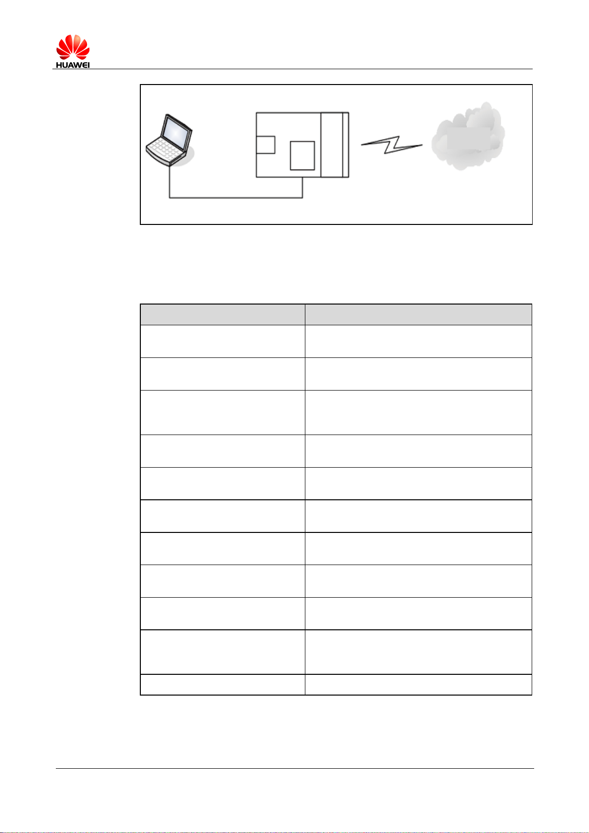
The ME909u-521 module provides three ports to interact with its host:
MODEM port: simulated using USB, for AT command interaction and
establishing data connection.
Port name: HUAWEI Mobile Connect-3G Modem
PCUI port: simulated using USB, for AT command interaction only.
Port name: HUAWEI Mobile Connect-3G PCUI Interface
ECM port: simulated using USB, for establishing communication connection.
Port name: CDC Ethernet Control Model (ECM)
The ME909u-521 also provides a port for debugging:
DIAG port: Simulated using USB, for DIAG (diagnostic) command interaction
(mainly used to debug modules at present).
Port name: HUAWEI Mobile Connect-3G Application Interface
A host controls a module using AT commands. If AT commands are unavailable, a
module can be deemed as unavailable.
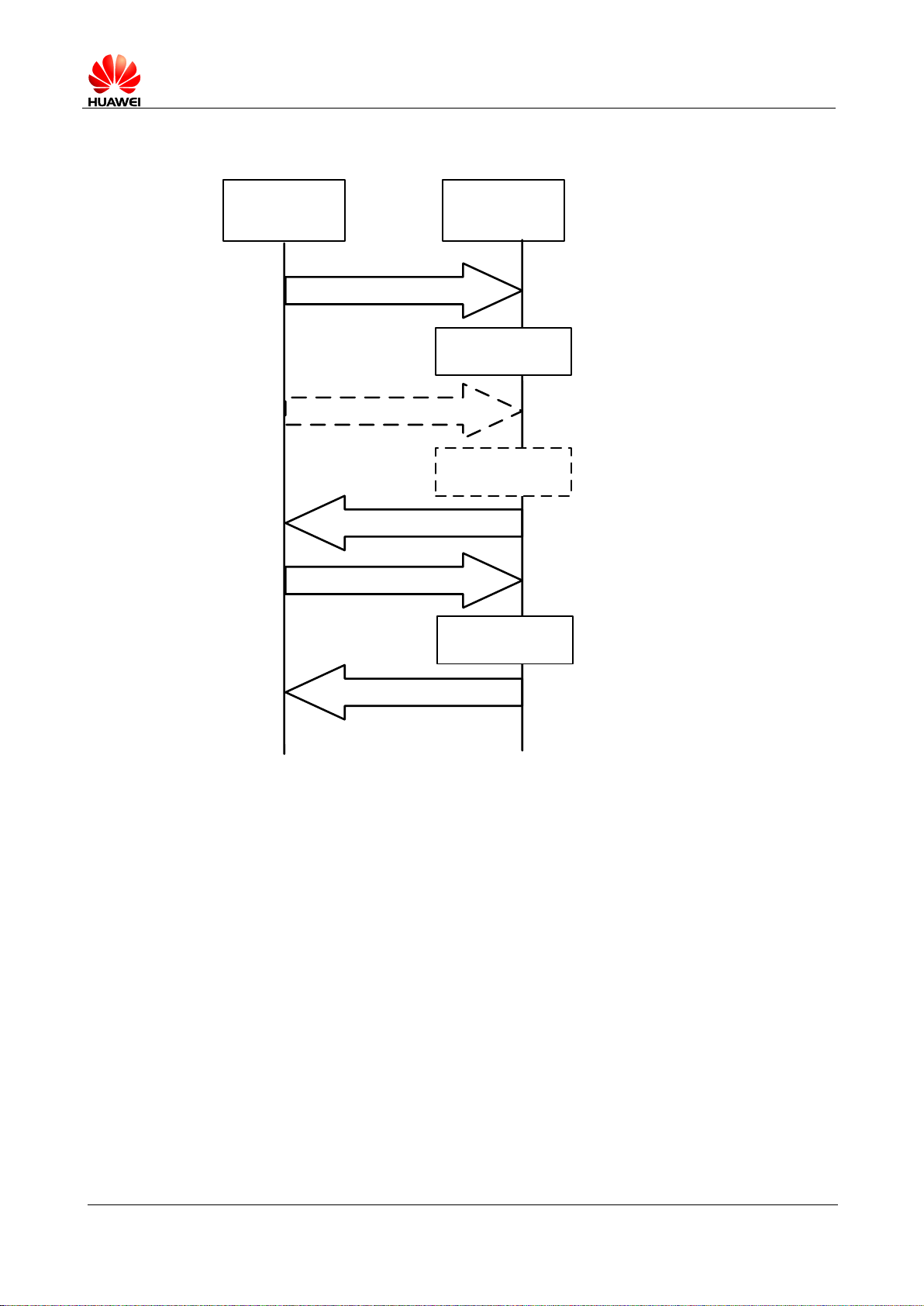
1.3.2 AT Command Processing Mechanism
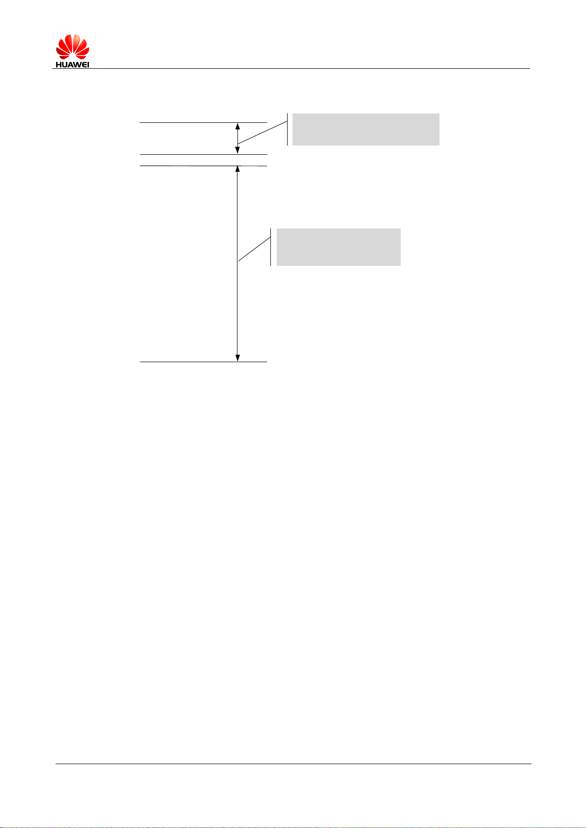
A module processes AT commands from the ports (MODEM, PCUI) in series. An AT
command can be processed when and only when the previous AT command
processing has been completed. If the module is processing an AT command, a new
AT command from the same port will be ignored and other commands from other
ports will be buffered until the current AT command is processed.
This rule also applies to COM ports converted from USB ports.
The processing of an AT command starts when the AT command is entered from the
TE, and ends when the UE (the module) returns all the results in response the
command.
Page 10
HUAWEI ME909u-521 LTE LGA Module
Application Guide
Overview
Issue 01 (2013-07-05)
Huawei Proprietary and Confidential
Copyright © Huawei Technologies Co., Ltd.
10
Figure 1-1 AT command processing sequence diagram
TE UE
AT command 1
AT command 2
Return results of AT command 1
AT command 3
Ignore AT
command 2
Process AT
command 1
Process AT
command 3
Return results of AT command 3
Page 11
HUAWEI ME909u-521 LTE LGA Module
Application Guide
Overview
Issue 01 (2013-07-05)
Huawei Proprietary and Confidential
Copyright © Huawei Technologies Co., Ltd.
11
Example:
AT+CPIN
?
+
CPIN:READY
OK
AT+CMGL
=
4
+
CMGL
:0,3,,
19
07813108608805
F
911320
B
813109730116
F
20000
A
705B3D84C4603
+
CMGL
:1,2,,
18
07813108608805
F
931FF0B813109730155
F
30000
A
704F4F29C0
E
+
CMGL
:2,2,,
18
07813108608805
F
931FF0B813109730155
F
30000
A
704F4F29C0
E
+
CMGL
:3,2,,
28
07813108608805
F
931FF0B813109730155
F
30000
A
71061
F69CAC2EBF69B5FA
4
D36CBC
168
+
CMGL
:4,2,,
24
07813108608805
F
931FF0B813109730155
F
30000
A70BB05C2D5DB7C1D4ECB
4
1
A
+
CMGL
:5,2,,
22
07813108608805
F
931FF0B813109730155
F
30000
A
7096E333B8
DCBE
77079
+
CMGL
:6,2,,
22
07813108608805
F
931FF0B813109730155
F
30000
A
70930598
D26A7DBDF
68
OK
All AT commands entered during
this period of time will be
ignored.
All AT commands entered
during this period of time will
be ignored.
Some special AT commands can be aborted by new AT commands. Such special
commands are called abortive commands.
The ME909u-521 supports the following abortive AT commands:
The AT+COPS Set command
AT+CLCK
Page 12
HUAWEI ME909u-521 LTE LGA Module
Application Guide
Overview
Issue 01 (2013-07-05)
Huawei Proprietary and Confidential
Copyright © Huawei Technologies Co., Ltd.
12
Example:
AT+COPS=1,2,23415
OK
Before the results ofAT+COPS
is returned, enter any characters
(such as"AT"), the module will
terminate the processing of
AT+COPS and returnOK. The
entered characters are used to
abort the command only .
AT Command
Timeout Duration
General AT commands
30s
AT+CMSS/AT+CMGS (used to send text
messages)
60s
AT+COPS=? (used to search for networks)
120s
Some commands can be executed when SIM card is inserted. It would return to SIM
failure if SIM card is not inserted. For more information, see Property Description of
related AT in HUAWEI ME909u-521 LTE LGA Module AT Command Interface Specification.
Example:
AT+CREG?
+CME ERROR: SIM failure
Note:
SIM failure indicate that SIM card is not inserted.
1.3.3 Recommended Timeout Mechanism for AT Commands Processed by a Host
A module processes AT commands in series. Do not send another AT command
before the result for the current command is returned or the current command times
out (except when the current command is an abortive AT command). The following
table lists AT command timeout durations (starting from the time when an AT
command arrives at a port).
Table 1-1 AT command timeout duration
After an AT command times out, it is recommended that the host check whether the
module is functioning normally. The following procedure is provided for your
reference:
1. The host sends AT to the module.
Page 13

HUAWEI ME909u-521 LTE LGA Module
Application Guide
Overview
Issue 01 (2013-07-05)
Huawei Proprietary and Confidential
Copyright © Huawei Technologies Co., Ltd.
13
2. If the module returns failure information, go to step 5.
3. If the module returns success information, the module is functioning normally.
4. If the host times out (the host waits for a response for over 30 seconds) three
times when waiting for the response from the module, go to step 5. Otherwise go
to step 1.
5. The host deems that the current module does not exist or is unavailable. Close
the port, stop sending all AT commands, exit the procedure to determine
whether the module is normal, and re-search for modules.
Page 14

HUAWEI ME909u-521 LTE LGA Module
Application Guide
Initialization Application Scenarios
Issue 01 (2013-07-05)
Huawei Proprietary and Confidential
Copyright © Huawei Technologies Co., Ltd.
14
2 Initialization Application Scenarios
Command
Description
A module, without solicitation, presents ^SYSSTART to
its host to indicate that the module is starting.
^SYSSTART
Indicate that a module is starting.
Scenario
Possible Error
Information
Solution
The module presents
^SYSSTART during startup.
After that, the module
presents ^SYSSTART again.
Indicate that the
module has been
reset.
If ^SYSSTART is presented
repeatedly, send the module
to the specified repair center.
2.1 Startup Indication ^SYSSTART
2.1.1 Reference Process
Notes:
^SYSSTART is presented only when a module is starting and will not be presented after a
module has started.
^SYSSTART is presented only after the radio frequency (RF) initialization completes and
will not be presented in offline mode.
2.1.2 Troubleshooting
Page 15
HUAWEI ME909u-521 LTE LGA Module
Application Guide
Initialization Application Scenarios
Issue 01 (2013-07-05)
Huawei Proprietary and Confidential
Copyright © Huawei Technologies Co., Ltd.
15
2.2 Querying Basic Information
Command
Description
AT+GMR/CGMR
Query software version.
Software version
OK
Software version. e.g. 11.103.03.00.00
AT+GMI/CGMI
Query manufacturer identification.
Manufacturer
Identification
OK
For example: Huawei Technologies Co., Ltd.
AT+GMM/CGMM
Query model identification.
Model identification
OK
For example: ME909u-521
AT+GSN/CGSN
Query product IMEI.
IMEI
OK
For example: 865261010004010
Scenario
Possible Error
Information
Solution
AT+GSN/CGSN
+CME ERROR: memory
failure
This error occurs when a
module's IMEI is not specified.
This problem is solved after
the IMEI is written into the
module.
2.2.1 Reference Process
Note:
The previously listed commands are Query commands and cannot be used to configure
settings.
2.2.2 Troubleshooting
Page 16

HUAWEI ME909u-521 LTE LGA Module
Application Guide
Initialization Application Scenarios
Issue 01 (2013-07-05)
Huawei Proprietary and Confidential
Copyright © Huawei Technologies Co., Ltd.
16
2.3 Network Service Operations
Command
Description
AT+CFUN?
Query a module's current mode. 1 indicates online
mode.
+CFUN: 1
OK
AT+CPIN?
Query whether a module's SIM card is password
protected. READY indicates that the SIM card is
ready.
+CPIN: READY
OK
AT^HCSQ?
Query the network signal quality.
^HCSQ:
"WCDMA",30,30,58
OK
AT+COPS?
Return the current network selection mode,
information about the operator with which the
module is registered, and the wireless access
standard.
+COPS: "Network status
information"
OK
For example: +COPS: 1,0, "China Mobile Com"
AT+COPS=0
Automatically search for networks.
OK AT+CREG?
Query the state of the currently registered network.
+CREG: 0,1
OK
AT+CREG=1
Set the +CREG unsolicited indication.
OK
2.3.1 Reference Process
Page 17

HUAWEI ME909u-521 LTE LGA Module
Application Guide
Initialization Application Scenarios
Issue 01 (2013-07-05)
Huawei Proprietary and Confidential
Copyright © Huawei Technologies Co., Ltd.
17
2.3.2 Troubleshooting
Scenario
Possible Error Information
Solution
AT+COPS?
+CME ERROR: SIM failure
No SIM card is detected. Insert
a SIM card.
AT+CREG?
+CME ERROR: SIM failure
No SIM card is detected. Insert
a SIM card.
Page 18

HUAWEI ME909u-521 LTE LGA Module
Application Guide
Network Searching and Registration Application
Scenarios
Issue 01 (2013-07-05)
Huawei Proprietary and Confidential
Copyright © Huawei Technologies Co., Ltd.
18
3 Network Searching and Registration
Command
Description
AT+COPS=0
Enable automatic search for networks.
OK
AT+COPS=1,2,"46000"
Manual search for the appointed network.
OK
AT+COPS=?
Search for all networks, and return the
networks.
OK
AT+CREG=2
Enable the unsolicited indication when
network registration state changes.
OK
AT^SYSCFGEX="00",3FFFFFFF
,1,2,7FFFFFFFFFFFFFFF,,
Set the system mode, network access order,
frequency band, roaming support, domain,
and other features.
OK
AT^SYSINFOEX
Query the system service state, domain,
roaming status, and system mode.
^SYSINFOEX:
2,3,0,1,,1,"GSM",3,"EDGE"
OK
AT^HCSQ?
Query the signal quality.
Application Scenarios
3.1 Searching and Registering Network
3.1.1 Reference Process
Page 19
HUAWEI ME909u-521 LTE LGA Module
Application Guide
Network Searching and Registration Application
Scenarios
Issue 01 (2013-07-05)
Huawei Proprietary and Confidential
Copyright © Huawei Technologies Co., Ltd.
19
Command
Description
^HCSQ:"GSM",73
OK
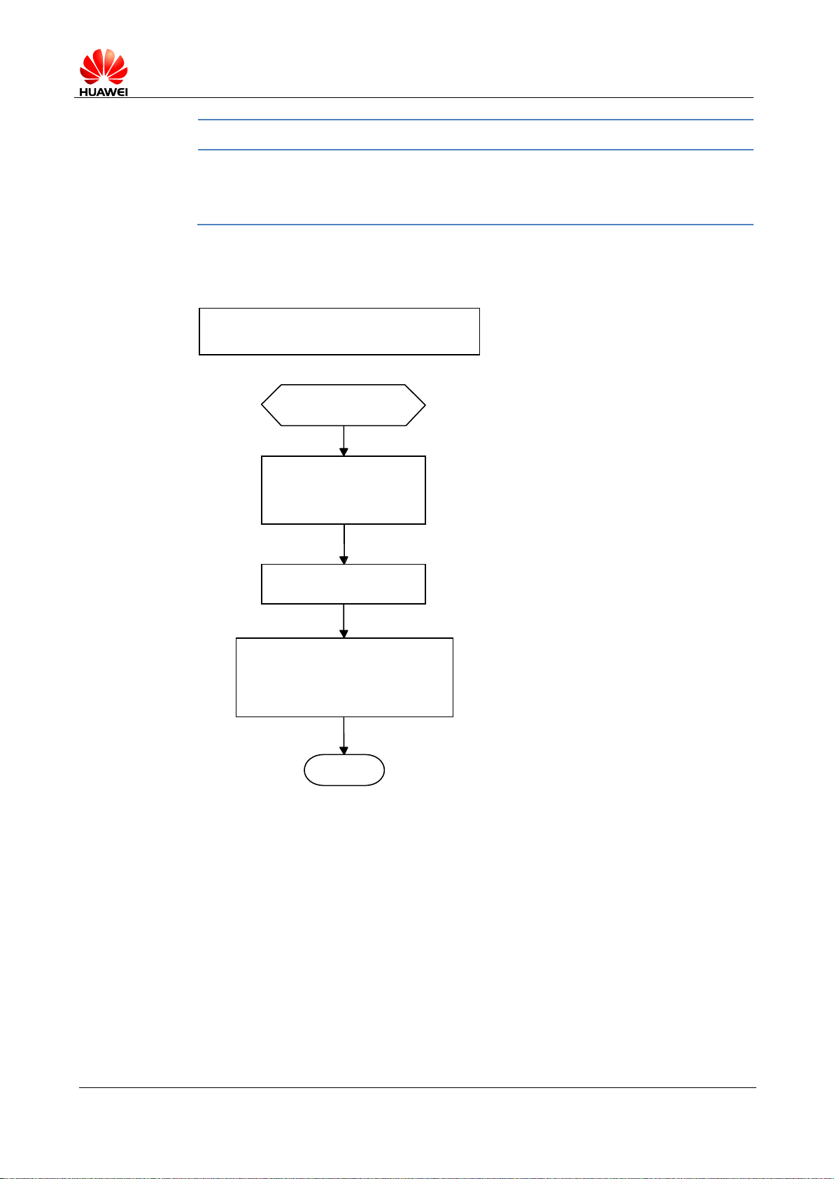
Automatic search for networks
Start
Enable automatic
search for networks.
AT+COPS=0
End
Return OK
The unsolication command
^SRVST indication for
the change of network state.
Figure 3-1 Automatic search for networks
Page 20
HUAWEI ME909u-521 LTE LGA Module
Application Guide
Network Searching and Registration Application
Scenarios
Issue 01 (2013-07-05)
Huawei Proprietary and Confidential
Copyright © Huawei Technologies Co., Ltd.
20
Figure 3-2 Manual search for networks
Manual search for networks
Start
Enable automatic
search for networks.
AT+COPS=?
Display the
networks found.
Select and register with a network.
AT+COPS=1[,<format>[,<oper>[,<rat>]]]
End
Scenario
Possible Error
Information
Solution
AT+COPS?
+CME ERROR: SIM
failure
No SIM card is detected. Insert
a SIM card.
AT+CREG?
+CME ERROR: SIM
failure
No SIM card is detected. Insert
a SIM card.
3.1.2 Troubleshooting
Page 21

HUAWEI ME909u-521 LTE LGA Module
Application Guide
ECM Application Scenarios
Issue 01 (2013-07-05)
Huawei Proprietary and Confidential
Copyright © Huawei Technologies Co., Ltd.
21
4 ECM Application Scenarios
Command
Description
AT^NDISDUP=?
Check the parameter range supported by
the command.
^NDISDUP: (1-16),(0-1)
OK
AT^NDISDUP=1,1,"1234"
Set up a dial-up connection using the
APN provided by the network server.
OK
^NDISSTAT: 1,,,"IPV4"
The command is successfully executed.
Report the dial-up connection state.
AT^NDISDUP=1,1,"4321","huawei",
"huawei",1
Set up a dial-up connection using the
account, password, and authentication
mode provided by the network server.
OK
^NDISSTAT: 1,,,"IPV4"
The command is successfully executed.
Report the dial-up connection state.
4.1 ECM Dialing
4.1.1 Reference Process
The process of obtaining the IP address:
1. After the dial-up is successful, the module will establish the DHCP service
automatically.
2. The PC driver will get the dial-up state and send net_ready state to the network
manage.
3. The network manage sends the DHCP service discover.
Page 22

HUAWEI ME909u-521 LTE LGA Module
Application Guide
ECM Application Scenarios
Issue 01 (2013-07-05)
Huawei Proprietary and Confidential
Copyright © Huawei Technologies Co., Ltd.
22
4. The module responses the service discover, and then sends the IP and DNS
Scenario
Possible Error Information
Solution
AT^NDISDUP=1,1,"1234
"
+CME ERROR: SIM failure
No SIM card is
detected. Insert a SIM
card.
AT^NDISDUP=1,1,"4321
","huaei","huawei",1
OK
^NDISSTAT: 0,33,,"IPV4"
^NDISEND:1,29
NDISEND indicates the
failure reason during the
dial-up.
29 indicates that the
authenticated
information is not
correct.
AT^NDISDUP=1,1,"abcd
"
OK
^NDISSTAT: 0,33,,"IPV4"
^NDISEND:1,33
NDISEND indicates the
failure reason during the
dial-up.
33 indicates that request
service is not specified.
In this case, the network
don not support this
APN "abcd".
Command
Description
AT^NDISSTATQRY?
Query the dial-up connection state.
^NDISSTATQRY: 0,0,,IPV4
OK
Report that the connection is not set up.
AT^NDISSTATQRY?
Query the dial-up connection state.
^NDISSTATQRY: 1,,,IPV4
OK
Report that the connection is set up.
address which is obtained from the PDP active process to the network managing
device.
4.1.2 Troubleshooting
4.2 Querying the Dial-up Connection State
4.2.1 Reference Process
Page 23

HUAWEI ME909u-521 LTE LGA Module
Application Guide
ECM Application Scenarios
Issue 01 (2013-07-05)
Huawei Proprietary and Confidential
Copyright © Huawei Technologies Co., Ltd.
23
4.2.2 Troubleshooting
Command
Description
AT^NDISDUP=1,0
Disconnect the dial-up connection.
OK
^NDISSTAT:0,,,"IPV4"
The command is successfully executed.
IPv4 changes from the connected state to
the disconnected state.
None
4.3 Disconnecting the Dial-up Connection
4.3.1 Reference Process
4.3.2 Troubleshooting
None
Page 24

HUAWEI ME909u-521 LTE LGA Module
Application Guide
SMS Application Scenarios
Issue 01 (2013-07-05)
Huawei Proprietary and Confidential
Copyright © Huawei Technologies Co., Ltd.
24
5.1 Overview
Short Message Service (SMS) is a text messaging service using a service center(SC)
to transfer short text messages between GSM MEs and Short Message Entities
(SMEs). ME909u-521 only supports protocol data unit (PDU) mode message.
A message must contain the following information before it is sent:
5 SMS Application Scenarios
For a PDU mode message:
Length of TPDU package
Message content: To compose or send a PDU mode message, the message
must contain all the message attributes and be encoded in PDU format. A PDU
consists of the following:
− Service Center Address (SCA): composed of the address length, SCA type
and SCA reverse byte.
− First octet: contains the message type indicator, TP-RP, TP-UDHI, TP-SRR,
TP-VPF, TP-RD, and TP-MTI.
− Short text message statement.
− Destination address: consisting of the destination address, address length
and destination address type.
− Protocol identifier.
− Data encoding scheme.
− Validity duration.
− Data length.
− User data: consisting of the user data header and the data encoded in PDU
format.
Figure 5-1 shows an example of data encoded in PDU format of submitted type.
Page 25

HUAWEI ME909u-521 LTE LGA Module
Application Guide
SMS Application Scenarios
Issue 01 (2013-07-05)
Huawei Proprietary and Confidential
Copyright © Huawei Technologies Co., Ltd.
25
Figure 5-1 Example of data encoded in PDU format of submitted type
SMS
Start
SMS initialization
Delete short
messages
Write short
messages
Receive
short messages
Read short
messages
Send short
messages
Status report
End
Figure 5-2 shows the general SMS process.
Figure 5-2 General SMS process
Page 26

HUAWEI ME909u-521 LTE LGA Module
Application Guide
SMS Application Scenarios
Issue 01 (2013-07-05)
Huawei Proprietary and Confidential
Copyright © Huawei Technologies Co., Ltd.
26
5.2 Initializing SMS
Command
Description
AT+CSCA?
Query the SMSC address.
+CSCA:
"13800688509",129
OK
AT+CSCA="+8613800755
500"
Set the SMSC address to the SMSC number of
China Mobile's Shenzhen Branch.
OK AT+CSMS?
Query the short message service type.
+CSMS: 0,1,1,1
OK
AT+CNMI?
Query the configuration of the new message
indications to TE.
+CNMI: 0,0,0,0,0
OK
AT+CNMI=2,1,2,2,0
Configure the new message indications to TE.
OK AT+CPMS?
Query the preferred short message storage.
+CPMS:
"SM",12,20,"SM",12,20,"S
M",12,20
OK
AT+CPMS="SM"
Set SM as short message storage medium.
OK
AT+CGSMS?
Query the MO SMS bearer domain.
+CGSMS: 1
OK
AT+CMGF?
Query the short message format.
+CMGF: 0
5.2.1 Reference Process
Page 27

HUAWEI ME909u-521 LTE LGA Module
Application Guide
SMS Application Scenarios
Issue 01 (2013-07-05)
Huawei Proprietary and Confidential
Copyright © Huawei Technologies Co., Ltd.
27
Command
Description
OK
AT+CMGF=0
Set the short message format to PDU.
OK
SMS initialization
Start
Query the SMSC
address.
Set the SMSC address to the SMSC
number of China Mobile's
Shenzhen Branch.
Set the message
service type.
Require the message
service type.
AT+CSCA?
AT+CSMS?
AT+CSMS=1
+CSCA: "",129
OK
+CSMS: 0,1,1,1
OK
*
OK
AT+CSCA="+8613800755500"
+CSMS: 1,1,1
OK
Example: SMSC
address is not specified.
Use the AT+CMGF command to set short message format: AT+CMGF=0 sets the
short message format to PDU.
The SMSC address provided by the service provider must be specified. In PDU mode,
the SMSC address is contained in the PDU packets. Therefore, in PDU mode, the
AT+CSCA command is optional.
To use the SMS features specified in the GSM 07.05 Phase 2+, the AT+CSMS
command must be used to enable the features.
Use the AT+CNMI command to set the unsolicited indications.
Use the AT+CPMS command to select the preferred short message storage (SIM or
ME). The ME909u-521 supports only the SM (SIM card) storage.
Use the AT+CGSMS command to select the MO SMS bearer domain (PS or CS
domain). For ME909u-521, the CS domain is the preferred MO bearer domain.
Figure 5-3 SMS initialization process – part 1
Page 28

HUAWEI ME909u-521 LTE LGA Module
Application Guide
SMS Application Scenarios
Issue 01 (2013-07-05)
Huawei Proprietary and Confidential
Copyright © Huawei Technologies Co., Ltd.
28
Figure 5-4 SMS initialization process – part 2
Query the unsolicited
indication state.
Enable the notification
of new messages.
Default values
Query the preferred storage
for the current message.
*
AT+CPMS?
AT+CGSMS?
+CNMI: 0,0,0,0,0
OK
AT+CNMI=2,1,2,2,0
+CGSMS: 1
OK
*
OK
+CPMS: "SM",13,20,"SM",13,20,"SM",13,20
OK
AT+CNMI?
AT+CMGF=0
Page 29

HUAWEI ME909u-521 LTE LGA Module
Application Guide
SMS Application Scenarios
Issue 01 (2013-07-05)
Huawei Proprietary and Confidential
Copyright © Huawei Technologies Co., Ltd.
29
Figure 5-5 SMS initialization process – part 3
End
OK
AT+CMGF=0
AT+CMGF?
*
+CMGF:0
OK
Scenario
Possible Error
Information
Solution
Error information is
returned in response to
one of the previous
commands.
+CME ERROR: SIM
PIN required
Enter the correct PIN.
+CMS ERROR: SIM
busy
SIM card initialization has not
completed. Try again later.
Command
Description
AT+CMGF=0
Set the short message format to PDU.
OK
AT+CSCA?
Query the SMSC address.
+CSCA: "13800688509",129
OK AT+CMGS=18
Send a PDU message without the service center
5.2.2 Troubleshooting
5.3 Sending Short Message
5.3.1 Reference Process
Page 30

HUAWEI ME909u-521 LTE LGA Module
Application Guide
SMS Application Scenarios
Issue 01 (2013-07-05)
Huawei Proprietary and Confidential
Copyright © Huawei Technologies Co., Ltd.
30
Command
Description
>0031000B813109731147F4
0000FF04F4F29C0E\x0A
address. The value of SMSC address is the setting
of +CSCA command.
+CMGS: 168
OK
The message is successfully sent.
AT+CMGS=18
>0891683108608805F93100
0B813109731147F40000FF0
4F4F29C0E\x1A
Send a PDU message with the correct service
center address.
+CMGS: 169
OK
The message is successfully sent.
AT+CMGS=18
>0891683108608805F03100
0B813109731147F40011FF0
4F4F29C0E\x1A
Send a PDU message with the wrong service
center address.
+CMS ERROR: Network out
of order
The message is unsuccessfully sent.
Messages in PDU format must be converted using external tools or users' software.
Tools for encoding and parsing messages in PDU format are available on the Internet.
Page 31

HUAWEI ME909u-521 LTE LGA Module
Application Guide
SMS Application Scenarios
Issue 01 (2013-07-05)
Huawei Proprietary and Confidential
Copyright © Huawei Technologies Co., Ltd.
31
Figure 5-6 Sending short messages in PDU format
Sending messages in PDU format
Start
Send a short message
(given that the PDU length is 18)
SMS initialization
PDU message
without SCA
Press <ctrl-Z> to send
the command.
Press <ESC> to cancel
the command
Example: Message
not sent
Message sent
unsuccessfully
End
AT+CMGS=18
+CMS ERROR:
Network out of
order
OK
0031000B813109731147F4
0000FF04F4F29C0E
<ESC>
0891683108608805F931000B
813109731147F40000FF04F4
F29C0E<ctrl-Z>
+CMGS:1
OK
Message sent
successfully
Scenario
Possible Error
Information
Solution
Error information is
returned in response
to one of the previous
commands.
+CMS ERROR: Network
out of order
Check the validity of the
service center address or the
state of the current network.
5.3.2 Troubleshooting
Page 32

HUAWEI ME909u-521 LTE LGA Module
Application Guide
SMS Application Scenarios
Issue 01 (2013-07-05)
Huawei Proprietary and Confidential
Copyright © Huawei Technologies Co., Ltd.
32
5.4 Reading Short Messages
Command
Description
AT+CMGL=0
List all received unread messages.
+CMGL: 2,0,,48
0891683108608805F9040D916831
09732097F2000001432619001001
F506215744FD3D1A0E930C8429
6D9EC370BFDE86C2F23228FFA
EFF00
+CMGL: 4,0,,64
0891683108608805F9040D916831
09732097F2000001403261310500
32506215744FD3D1A0E930C8429
6D9EC370BFDBE83C2B0380F6A
97416FF7B80C6AVFE5E510
OK
The format of short messages can refer to
the AT+CMGL command.
AT+CMGR=4
Read the message stored in the message
storage location 4.
+CMGR: 1,,64
0891683108608805F9040D916831
09732097F2000001403261310500
32506215744FD3D1A0E930C8429
6D9EC370BFDBE83C2B0380F6A
97416FF7B80C6AVFE5E510
OK
The format of short messages can refer to
the AT+CMGR command.
Message State
PDU Mode
Received unread messages
0
Received read messages
1
Stored unsent messages
2
Stored sent messages
3
5.4.1 Reference Process
There are two methods to read short messages:
Method 1: Use the AT+CMGL command to list the messages that are in
specified state and stored in the preferred message storage. The following table
describes the message states. If the message sate is received unread
messages, the REC UNREAD state will be changed to REC READ after the
AT+CMGL command is executed.
Page 33

HUAWEI ME909u-521 LTE LGA Module
Application Guide
SMS Application Scenarios
Issue 01 (2013-07-05)
Huawei Proprietary and Confidential
Copyright © Huawei Technologies Co., Ltd.
33
Message State
PDU Mode
All messages
4
Reading short messages
Start
List received unread
messages in PDU format
+CMGL:<index1>,0,,<length>
<pdu> (messages in PDU format)
......
+CMGL:<indexn>,0,,<length>
<pdu> (messages in PDU format)
OK
PDU format
+CMGR:n,,<length>
<pdu> (messages in PDU format)
OK
End
AT+CMGL=0
AT+CMGR=n
Method 2: Use the AT+CMGR command to read a message from a specified
storage location in the message storage. If the message is a received unread
message, its state will be changed to REC READ after it is read using the
AT+CMGR command.
You can use the AT+CMGL command to list all short messages so that you can view
the messages' storage locations.
Figure 5-7 Reading short messages
Page 34

HUAWEI ME909u-521 LTE LGA Module
Application Guide
SMS Application Scenarios
Issue 01 (2013-07-05)
Huawei Proprietary and Confidential
Copyright © Huawei Technologies Co., Ltd.
34
5.4.2 Troubleshooting
Scenario
Possible Error
Information
Solution
Error information is
returned in response
to one of the previous
commands.
+CMS ERROR: invalid
memory index
Check the validity of the index.
Command
Description
AT+CMGF=0
Set the message format to PDU mode.
OK AT+CMGL=4
List all short messages (PDU mode).
+CMGL: 6,2,,30
0011000A917179876213000
0A713C8329BFD6681D0EF
3B282C2F83F2EFFA0F
+CMGL: 11,1,,36
0791947106004013240C919
47159826990000030804131
15748013C8329BFD6681D0
EF3B282C2F83F2EFFA0F
OK AT+CMGD=1
Delete the message stored in storage location 1.
OK
5.5 Deleting Short Messages
5.5.1 Reference Process
Either all messages stored in the preferred message storage or a message
stored in the specified storage location in the preferred message storage can be
deleted.
All read or unread messages that have been received can be deleted.
If no messages are stored in the preferred message storage, "OK" is returned
when the action to delete messages is completed.
Meanings of the DelFlag value:
− 1: Delete all read messages in the preferred message storage, and keep the
unread, sent and unsent messages.
Page 35

HUAWEI ME909u-521 LTE LGA Module
Application Guide
SMS Application Scenarios
Issue 01 (2013-07-05)
Huawei Proprietary and Confidential
Copyright © Huawei Technologies Co., Ltd.
35
− 2: Delete all read and sent messages in the preferred message storage, and
Deleting short messages
Start
Prerequisite:
SMS has been initialized.
Example: Lists all short
messages in PDU format.
Delete the message
stored in
location n in the preferred
storage.
Equivalent to
AT+CMGD=n
End
OK
+CMSERROR:
AT+CMGD=n AT+CMGD=n,0
AT+CMGL=4
AT+CMGD=x,DelFlag
X:(0-999)
+CMGL: 1,<parameters>
07919471060040
+CMGL: 2,<parameters>
07919471060040
......
invalid memory
index
Scenario
Possible Error
Information
Solution
Error information is
returned in response
to one of the previous
commands.
+CMS ERROR: invalid
memory index
Check the validity of the index.
keep the unread and unsent messages.
− 3: Delete all read, sent, and unsent messages in the preferred message
storage, and keep the unread messages.
− 4: Delete all messages in the preferred message storage, including the
unread messages.
Figure 5-8 Deleting short message
5.5.2 Troubleshooting
Page 36

HUAWEI ME909u-521 LTE LGA Module
Application Guide
Phonebook Application Scenarios
Issue 01 (2013-07-05)
Huawei Proprietary and Confidential
Copyright © Huawei Technologies Co., Ltd.
36
6 Phonebook Application Scenarios
Command
Description
AT+CPBS=?
Query the current storage type.
+CPBS: ("SM","EN","ON")
OK
AT+CPBS="SM"
Set the current storage type to "SM".
OK
AT+CPBS?
241 indicates that 241 entries have been
stored in the storage. 250 indicates that the
maximum storage capacity of the current
storage ("SM") is 250 entries.
+CPBS: "SM",241,250
OK
6.1 Overview
As a product embedded into a host, the phonebook scenarios include that read, write,
query and delete the phonebook entries in the SIM card.
Read Phonebook: use the AT+CPBR command to read phonebook entries.
Write phonebook: use the AT+CPBW command to save the phonebook entries into
the SIM card.
Delete phonebook: use AT+CPBW command to delete the phonebook entries in the
SIM card.
6.2 Memory Operations
6.2.1 Reference Process
Page 37

HUAWEI ME909u-521 LTE LGA Module
Application Guide
Phonebook Application Scenarios
Issue 01 (2013-07-05)
Huawei Proprietary and Confidential
Copyright © Huawei Technologies Co., Ltd.
37
Note that the AT commands for reading and writing phonebook entries can be used
Initializing the phonebook
Start
Query the available
storage types for the phonebook.
Query the current phonebook storage.
Select SM as the storage type
End
OK
AT+CPBS=“SM”
+CPBS:“ON”,0,0
OK
AT+CPBS?
AT+CPBS=?
+CPBS:(“SM”,“EN”,“ON”)
OK
Scenario
Possible Error
Information
Solution
Error information is
returned in response to
one of the previous
commands.
+CME ERROR: SIM
busy
Phonebook initialization has
not completed. Try again
later.
+CME ERROR: SIM PIN
required
Enter the correct PIN.
only after the phonebook storage is selected. To select a phonebook storage, use the
AT+CPBS command.
Figure 6-1 Initializing the phonebook
6.2.2 Troubleshooting
Page 38

HUAWEI ME909u-521 LTE LGA Module
Application Guide
Phonebook Application Scenarios
Issue 01 (2013-07-05)
Huawei Proprietary and Confidential
Copyright © Huawei Technologies Co., Ltd.
38
Scenario
Possible Error
Information
Solution
+CME ERROR: SIM
PUK required
Enter the correct PUK.
Command
Description
AT+CPBS?
Query the phonebook storage selection and the
maximum number of entries that can be stored.
+CPBS: "SM",9,20
OK AT+CPBR=1,20
List all phonebook entries by their indexes.
+CPBR:
1,"+491765864491",145,"J
ohn Smith"
+CPBR:
2,"+44545896638",145,"Pa
ul Williams"
+CPBR:
3,"+44556565657",145,"Jo
e Anderson"
+CPBR:
4,"+445636934485",145,"
Oscar Thomso”
+CPBR:
5,"+445565656899",145,"H
annah Adams"
+CPBR:
6,"+447982865563",145,"S
amantha Young"
+CPBR:
7,"+449585315798",145,"A
lexis Wright"
+CPBR:
8,"+445415454646",145,"A
bigail Cox"
+CPBR:
12,"+446565689115",145,"
Kyla Clark"
6.3 Reading Phonebook Entries
6.3.1 Reference Process
Page 39

HUAWEI ME909u-521 LTE LGA Module
Application Guide
Phonebook Application Scenarios
Issue 01 (2013-07-05)
Huawei Proprietary and Confidential
Copyright © Huawei Technologies Co., Ltd.
39
Command
Description
OK
Reading phonebook entries
Start
Query the current phonebook storage type.
Initialize the
phonebook.
FD phonebook can store
up to 10 entries; currently 3
entries are stored.
Correct response
Lists all phonebook entries from location x to location y.
The ending location is greater
than the greatest phonebook entry index.
End
+CPBS:“SM”,4,250
OK
+CPBS:“ON”,1,4
OK
AT+CPBR=x,y
+CME ERROR:
invalid index
+CPBR:
1,“+491765864491”,145,“JohnSmith”
+CPBR:
2,“+445564854245”,145,“AshleyJones”
...
OK
Scenario
Possible Error
Information
Solution
Error information is
returned in response
to one of the previous
commands.
+CME ERROR: SIM
busy
Phonebook initialization has
not completed. Try again later.
+CME ERROR: SIM PIN
required
Enter the correct PIN.
+CME ERROR: SIM
PUK required
Enter the correct PUK.
Figure 6-2 Reading phonebook entries
6.3.2 Troubleshooting
Page 40

HUAWEI ME909u-521 LTE LGA Module
Application Guide
Phonebook Application Scenarios
Issue 01 (2013-07-05)
Huawei Proprietary and Confidential
Copyright © Huawei Technologies Co., Ltd.
40
Scenario
Possible Error
Information
Solution
AT+CPBR=<index1>
+CME ERROR: invalid
index
The index is invalid. Check
that index 1 is within the
supported range.
AT+CPBR=<index1>,
<index2>
+CME ERROR: invalid
index
The index is invalid. Check
that index 1 and index 2 are
within the supported range and
that index 1 is not greater than
index 2.
AT+CPBR=<index1>
+CME ERROR: not
found
No entries are found in the
storage locations in index 1.
Check that there have been
entries successfully written into
these locations.
AT+CPBR=<index1>,
<index2>
+CME ERROR: not
found
No entries are found in the
storage locations between
index 1 and index 2. Check
that there have been entries
successfully written into these
locations.
Command
Description
AT+CPBR=?
Query the ranges of parameters related to the
phonebook entries.
+CPBR: (1-250),24,14
OK
AT+CPBW="5","13903702
805",,"test"
Write a phonebook record.
OK
AT+CPBW=1
Delete the entry in index 1 in the phonebook.
OK
6.3.3 Writing/Deleting Phonebook Entries
6.3.4 Reference Process
There are two methods to edit phonebook entries using the AT+CPBW command:
Write an entry to a specified location. This method edits the location where a
phonebook entry exists or writes a new entry to a vacant location.
Page 41

HUAWEI ME909u-521 LTE LGA Module
Application Guide
Phonebook Application Scenarios
Issue 01 (2013-07-05)
Huawei Proprietary and Confidential
Copyright © Huawei Technologies Co., Ltd.
41
Writing phonebook entries
Start
AT+CPBR=?
+CPBR: (1-250),20,16
OK
+CPBR: 1,"+491765864491",145,"John Smith"
+CPBR: 3,"+441236548545",145,"Emily Miller"
Query the ranges of
parameters related
to the phonebook
entries.
Parameter ranges
Read all phonebook entries.
Read all the returned results.
Write phonebook
parameters.
AT+CPBW=,"+44546465
4568",145,"Paul Williams"
OK
+CEM ERROR:
memory full
+CEM ERROR:
invalid index
AT+CPBW=1,"+44546465
4568",145,"Paul Williams"
Write a phonebook
entry to a vacant location.
Write a phonebook entry
to a specified location.
Note: If an entry already
exists in the location,
the entry will be overwritten.
End
Scenario
Possible Error
Information
Solution
Error information is
returned in response to
one of the previous
+CME ERROR: SIM
busy
Phonebook initialization has
not completed. Try again
later.
Write a new phonebook entry to the next location of a location that already has a
phonebook entry. This method does not require a specified storage location. The
AT+CPBW command can be used to edit phonebook entries of the "SM" or "ON"
type.
Figure 6-3 Writing phonebook entries
6.3.5 Troubleshooting
Page 42

HUAWEI ME909u-521 LTE LGA Module
Application Guide
Phonebook Application Scenarios
Issue 01 (2013-07-05)
Huawei Proprietary and Confidential
Copyright © Huawei Technologies Co., Ltd.
42
Scenario
Possible Error
Information
Solution
commands.
+CME ERROR: SIM
PIN required
Enter the correct PIN.
+CME ERROR: SIM
PUK required
Enter the correct PUK.
Error information is
returned when writing an
entry into the
phonebook.
+CME ERROR: dial
string too long
Check that the phone
number is not too long.
Error information is
returned in response to
one of the previous
commands.
+CME ERROR: invalid
index
Check that the location index
and phone number type are
valid.
Error information is
returned when writing an
entry into the
phonebook.
+CME ERROR: invalid
characters in dial string
The phone number to be
written into the phonebook
contains invalid characters.
Delete the invalid characters
and try again.
AT+CPBW=,"123456789
01234567890123",128,"
80534E4E3A"
+CME ERROR:
memory full
The storage is full. Delete
some entries and try again.
Command
Description
AT+CPBF=<findtext>
Search the current storage for
phonebook entries that contain
the <findtext> field.
+CBPF: <index1>,<number>,<type>,<text>
+CBPF: <index2>,<number>,<type>,<text>
...
OK
AT+CPBF=?
Return the maximum phone
number length and maximum
name length supported by the
current phonebook storage.
+CPBF: <nlength>,<tlength>
6.4 Searching for Phonebook Entries
6.4.1 Reference Process
Page 43

HUAWEI ME909u-521 LTE LGA Module
Application Guide
Phonebook Application Scenarios
Issue 01 (2013-07-05)
Huawei Proprietary and Confidential
Copyright © Huawei Technologies Co., Ltd.
43
OK
Scenario
Possible Error
Information
Solution
Error information is returned
in response to one of the
previous commands.
+CME ERROR: SIM
busy
Phonebook initialization has
not completed. Try again
later.
+CME ERROR: SIM
PIN required
Enter the correct PIN.
+CME ERROR: SIM
PUK required
Enter the correct PUK.
AT+CPBF=<findtext>
+CME ERROR: not
found
No matches were found.
Check whether the current
phonebook storage has
entries that match the search
criterion.
Command
Description
AT+CNUM
Query the SIM number.
+CNUM: [<alpha1>],<number1>,<type1>
+CNUM: [<alpha2>],<number2>,<type2>
...
OK
6.4.2 Troubleshooting
6.5 Querying User Number
6.5.1 Reference Process
Page 44

HUAWEI ME909u-521 LTE LGA Module
Application Guide
Phonebook Application Scenarios
Issue 01 (2013-07-05)
Huawei Proprietary and Confidential
Copyright © Huawei Technologies Co., Ltd.
44
6.5.2 Troubleshooting
Scenario
Possible Error
Information
Solution
Error information is
returned in response to
one of the previous
commands.
+CME ERROR: SIM
busy
Phonebook initialization has
not completed. Try again
later.
+CME ERROR: SIM PIN
required
Enter the correct PIN.
+CME ERROR: SIM
PUK required
Enter the correct PUK.
Command
Description
AT+CSCS=?
Query the character sets supported by the
UE.
+CSCS: ("IRA","GSM","UCS2")
OK
AT+CSCS?
Query the current character set.
+CSCS: "IRA"
OK
AT+CPBR=1
Read the first phonebook entry. The TE
character set is the International
Reference Alphabet (IRA). The content of
the first entry's name field is "HUAWEI".
+CPBR:
1,"0123456789",129,"HUAWEI"
OK
AT+CSCS="UCS2"
Set the TE's character set to UCS
alphabet.
OK
AT+CPBW=1,"0123456789",129,"00
4800550041005700450049"
The character set is the UCS alphabet.
The content of the phonebook entry's
6.6 Setting the TE's Character Sets
6.6.1 Reference Process
Page 45

HUAWEI ME909u-521 LTE LGA Module
Application Guide
Phonebook Application Scenarios
Issue 01 (2013-07-05)
Huawei Proprietary and Confidential
Copyright © Huawei Technologies Co., Ltd.
45
name field is
004800550041005700450049, which is
"HUAWEI" in the IRA.
OK
AT+CPBR=1
Read the first phonebook entry. The TE
character set is UCS alphabet. The
content of the first entry's name field is
004800550041005700450049 ("HUAWEI"
in the IRA).
+CPBR:
1,"0123456789",129,"004800550041
005700450049"
OK
6.6.2 Troubleshooting
None
Page 46

HUAWEI ME909u-521 LTE LGA Module
Application Guide
SIM Operation Application Scenarios
Issue 01 (2013-07-05)
Huawei Proprietary and Confidential
Copyright © Huawei Technologies Co., Ltd.
46
7 SIM Operation Application Scenarios
Command
Description
AT+CLCK="SC",1,"<pwd>"
Enable PIN authentication. (<pwd>
specifies the PIN. See note 1.)
OK AT+CLCK="SC",2
Request the SIM card state.
+CLCK: 1
OK
"+CLCK: 1" means that the SIM card is
not blocked.
AT+CLCK="SC",0," <pwd>"
Disable the SIM card lock. (<pwd>
specifies the PIN. See note 1.)
OK
AT+CLCK="SC",2
Request the SIM card state.
+CLCK: 0
OK
"+CLCK: 0" means that the SIM card is
not blocked.
AT+CLCK="SC",1,"<pwd>"
Enable PIN authentication. (<pwd>
specifies the PIN. See note 1.)
OK
AT+CPIN="<pwd>"
Request the PIN after the module
restarts.
OK
AT+CPIN?
Request the PIN state.
+CPIN: READY
7.1 PIN Operations
7.1.1 Reference Process
Page 47

HUAWEI ME909u-521 LTE LGA Module
Application Guide
SIM Operation Application Scenarios
Issue 01 (2013-07-05)
Huawei Proprietary and Confidential
Copyright © Huawei Technologies Co., Ltd.
47
OK
AT+CLCK="SC",2
Request the SIM card state.
+CLCK: 1
OK
"+CLCK: 1" means that the SIM card is
not blocked.
AT+CPWD="SC","<oldpwd>","1234"
Change the PIN (1234 will be the new
PIN).
OK
AT+CPWD="SC","1113","1233"
Enter an incorrect PIN (first attempt).
+CME ERROR: incorrect password
AT+CPWD="SC","3333","1233"
Enter an incorrect PIN (second attempt).
+CME ERROR: incorrect password
AT+CPWD="SC","4711","1233"
Enter an incorrect PIN (third attempt).
+CME ERROR: SIM PUK required
AT+CPIN?
Check whether the password is
requested.
+CPIN: SIM PUK
OK
AT+CPIN="12345678","0000"
Enter the SIM PUK and specify the new
SIM PIN (activate new "SC" lock).
OK
Scenario
Possible Error
Information
Solution
Enable PIN authentication.
AT+CLCK="SC",1,"<pwd>"
+CME ERROR:
operation not
allowed
If PIN authentication has
been enabled, it cannot be
enabled again. Check
whether PIN authentication
has been enabled.
Notes:
After PIN authentication is enabled using +CLCK, the module must be restarted for the
change to take effect.
Either ^CPIN or +CPIN can be used to authenticate the PIN.
7.1.2 Troubleshooting
Page 48

HUAWEI ME909u-521 LTE LGA Module
Application Guide
SIM Operation Application Scenarios
Issue 01 (2013-07-05)
Huawei Proprietary and Confidential
Copyright © Huawei Technologies Co., Ltd.
48
Scenario
Possible Error
Information
Solution
Enter the PIN.
AT+CPIN="<pwd>"
+CME ERROR:
incorrect password
Enter the correct PIN. The
original PIN is provided by
the operator.
+CME ERROR: SIM
PUK required
Incorrect PINs have been
entered three times and the
SIM card is blocked. Run
AT+CPIN="<PUK>","<pwd>
" to enter the PUK to unblock
the SIM card. The PUK is
provided by the operator and
cannot be changed by users.
If incorrect PUKs are entered
10 times, the SIM card will be
permanently blocked.
Changes the PIN.
AT+CPWD="SC","<oldpwd
>","<newpwd>"
+CME ERROR:
incorrect password
<oldpwd> must be the
current PIN. Like the PIN
authentication, if incorrect
PINs are entered three times,
the PUK will be required. If
incorrect PUKs are entered
10 times, the SIM card will be
permanently blocked.
Command
Description
AT+CRSM=176,12258,0,0,10
Read the file EFiccid with a transparent
structure. (12258 is 0X2FE2, the
EFiccid file's FID).
+CRSM: 144,0,"<record>"
OK
After the command is processed
successfully, the EFiccid file's content
(<record>) is returned.
AT+CRSM=178,28476,1,4,176,,"7F10"
Use an absolute path to read the first
entry from the EFsms file on the SIM
card's DFtelecom folder.
+CRSM: 144,0,"<record>"
OK
<record> is the content of the first entry.
The length of <record> is 176 bytes.
AT+CRSM=192,12258
Get response of EFiccid.
7.2 CRSM Command
7.2.1 Reference Process
Page 49

HUAWEI ME909u-521 LTE LGA Module
Application Guide
SIM Operation Application Scenarios
Issue 01 (2013-07-05)
Huawei Proprietary and Confidential
Copyright © Huawei Technologies Co., Ltd.
49
+CRSM: 144,0,"<response>"
OK
<response> is the response data of
EFiccid. For details about <response>,
refer to the ETSI TS 102.221 protocol.
AT+CRSM=214,28421,0,0,2,"0012"
Update the content of the transparent
structure EFli file on the SIM card.
+CRSM: 144,0,""
OK
Update succeeded.
AT+CRSM=220,28476,1,4,176,"1111",
"7F10"
Update the content of the linear fixed
structure EFsms file on the SIM card.
+CRSM: 144,0,""
OK
Update succeeded.
AT+CRSM=242
Obtain the current directory information.
+CRSM: 108,"<length>","<status>"
OK
<length> indicates <status>’s length in
byte.
<status> indicates the current directory
status by hexadecimal.
Notes:
To read or update a file, appropriate commands must be used according to the file's
structure type (for details, refer to the description of file properties in the 3GPP TS 31.102
protocol). For transparent structure files, use 176 (Read Binary) and 214 (Update Binary).
For linear fixed structure files, use 178 (Read Record) and 220 (Update Record).
If <pathid> is not contained in the command, the module will prefer to access the files with
the same FID in the current directory.
Files can be accessed only when the access criteria are met. Otherwise the SIM card will
return PSWs indicating that the access authentication failed. If an EF file's read privilege is
PIN protected and the module does not have the PIN authenticated, PSWs indicating that
the access authentication failed will be returned after the +CRSM command is used to read
the EF file.
To use the +CRSM command to access the file content on the SIM card, the parameters
contained in the command must strictly meet the requirements in the ETSI TS 10.2221 and
3GPP TS 31.102. For detailed requirements, refer to the ETSI TS 102.221 and 3GPP TS
31.102
Page 50

HUAWEI ME909u-521 LTE LGA Module
Application Guide
SIM Operation Application Scenarios
Issue 01 (2013-07-05)
Huawei Proprietary and Confidential
Copyright © Huawei Technologies Co., Ltd.
50
7.2.2 Troubleshooting
Scenario
Possible Error
Information
Solution
Update the content of the
linear fixed structure EFsms
file on the SIM card.
AT+CRSM=178,12258,0,0,
10
+CRSM: 105,129,""
OK
The status word (SW)
indicates a Read command
error occurred. Files with a
transparent structure should be
read using 176 (READ
BINARY).
Update the content of the
linear fixed structure EFsms
file on the SIM card.
AT+CRSM=220,28476,1,4,
176,"1111","7F10"
+CRSM: 105,130,""
OK
The PSW indicates that the
security conditions were not
met. To update the EFsms
file, the correct PIN is
required.
Page 51

HUAWEI ME909u-521 LTE LGA Module
Application Guide
Sleeping and Waking Up Application Scenarios
Issue 01 (2013-07-05)
Huawei Proprietary and Confidential
Copyright © Huawei Technologies Co., Ltd.
51
8 Sleeping and Waking Up Application
Scenarios
As an embedded component in the host, the module also consumes power, which
increases the power consumption of the integrated product. Therefore, the most
important task of power management is to reduce the power consumption of the
integrated product by enabling the module's sleep mode when necessary.
The host and the module need to wake each other up from sleep if communication is
required. Therefore, another task of power management is to provide a wake-up
control mechanism for the host and module.
Power management involves three parts: the host system software (including the
USB driver/UART driver/GPIO driver/sleep mechanism functions), connection
hardware between the host and module, and the module's software wake-up
mechanism.
This chapter is mainly concerned with the module's software wakeup mechanism,
including the wake-up principle, how USB related events impact on the waking up of
the module and remotely waking up the module, and how the module remotely wakes
up the host.
This chapter briefly describes the power management related connection hardware
between the host and module.
This chapter does not describe the host system software. For example, if the host
runs on a Windows or Mac system, Huawei will provide a USB driver program
corresponding to the module. If the host runs on an Android system, Huawei will
provide HUAWEI Module Android RIL Integration Guide for users to configure the
USB-based wakeup function of the module. If the host runs on a Linux system, power
management is supported only when the Linux Kernel version is 2.6.35 or later.
This document describes typical module application scenarios. A host can be
designed based on the actual system features and the application scenarios of the
module to reduce power consumption of both the module and integrated product.
After the host is designed as recommended by this document, the module's power
consumption and the whole unit's power consumption can meet the performance
requirements. For details, see related description in the product manual.
Page 52

HUAWEI ME909u-521 LTE LGA Module
Application Guide
Sleeping and Waking Up Application Scenarios
Issue 01 (2013-07-05)
Huawei Proprietary and Confidential
Copyright © Huawei Technologies Co., Ltd.
52
8.1 Hardware Interfaces
Interface
Pin name
Direction
Functional Description
Diagram
PCIE
WAKE#
Output
When a wake-up source arrives, this
pin output a low-level-voltage pulse
lasting for 1s during which if other
wake-up sources arrive, the module
will ignore the later wake-up requests.
In other words, the module will not
output a second pulse during this 1s.
Figure 8-1
LGA
WAKEUP_OUT
Output
When a wake-up source arrives, this
pin output a high-level-voltage pulse
lasting for 1s during which if other
wake-up sources arrive, the module
will ignore the later wake-up requests.
In other words, the module will not
output a second pulse during this 1s.
Figure 8-2
LGA
WAKEUP_IN
Input
When the pin carries a high-level
voltage, the states of the module are
as follows:
The module will be prohibited to enter
sleep mode if the module is awake.
The module will be woken up if the
module is in sleep mode.
When the pin carries a low-level
voltage, the module is allowed to enter
sleep mode. (By default, the pin is set
to INPUT/PD, which is, the software
detects a low-level voltage on the pin
when the pin is not connected.)
Figure 8-3
LGA
SLEEP_STATUS
Output
Indicate the state of the module.
When the pin carries a high-level
voltage, the module is in working
mode. When the pin carries a lowlevel voltage, the module is in sleep
mode.
Figure 8-4
The module communicates with the host using mainly USB or UART. For details
about pins related to power management, see Table 8-1 .
For corresponding interface numbers and reference design for the pins, see
Hardware Guide for each product.
Table 8-1 Power management related pins
Note:
The PCIE interface does not support UART.
Page 53

HUAWEI ME909u-521 LTE LGA Module
Application Guide
Sleeping and Waking Up Application Scenarios
Issue 01 (2013-07-05)
Huawei Proprietary and Confidential
Copyright © Huawei Technologies Co., Ltd.
53
8.2 Sequence Diagram
Figure 8-1 WAKE# PIN output sequence
Figure 8-2 WAKEUP_OUT PIN output sequence
Page 54

HUAWEI ME909u-521 LTE LGA Module
Application Guide
Sleeping and Waking Up Application Scenarios
Issue 01 (2013-07-05)
Huawei Proprietary and Confidential
Copyright © Huawei Technologies Co., Ltd.
54
Figure 8-3 WAKEUP_IN PIN input sequence
About the vote, see section 8.3.1 .
Figure 8-4 SLEEP_STATUS PIN output sequence
8.3 Software Interfaces
8.3.1 Principle
The module runs on a multi-task software system. The sleep task is granted with the
lowest priority and assigned to detect whether the module can enter sleep mode.
Other tasks (such as the RF, SIM card, USB) have voting rights. They vote to decide
whether the module can enter sleep mode. When no other tasks are running, the
sleep task is executed. If the sleep task detects that all other tasks agree on the
module's sleep, the module enters sleep mode, as shown in Figure 8-5 . At this time,
the baseband chip reduces the work frequency, and the RF enters the Discontinuous
Reception (DRX) mode.
Page 55

HUAWEI ME909u-521 LTE LGA Module
Application Guide
Sleeping and Waking Up Application Scenarios
Issue 01 (2013-07-05)
Huawei Proprietary and Confidential
Copyright © Huawei Technologies Co., Ltd.
55
Figure 8-5 Currency state when the module is in sleep mode
T 2(S EELP )
T 1(W ak eup)
For more information about the module's sleep procedure, see Figure 8-6
Note:
The module's sleep mode is different from working mode or flight mode set using the
AT+CFUN command. The RF will be turned off when the module enters LPM mode using the
command AT+CFUN=0 while the RF will enter DRX mode without being turned off when the
module is in sleep mode. For more details, refer to HUAWEI ME909u-521 LTE LGA Module AT
Command Interface Specification.
The module enters sleep mode automatically when the sleep task detects that all
other tasks agree on the module's sleep. The sleep period of the module depends on
the current working state and circumstance. The period may last for several seconds,
or up to several minutes.
Page 56

HUAWEI ME909u-521 LTE LGA Module
Application Guide
Sleeping and Waking Up Application Scenarios
Issue 01 (2013-07-05)
Huawei Proprietary and Confidential
Copyright © Huawei Technologies Co., Ltd.
56
Figure 8-6 Sleep procedure
8.3.2 USB and Sleep
USB is an important communication channel between the module and the host.
According to the USB protocol, normally a hub or a root hub periodically sends Start
of Frame (SOF) data packages (one data package per ms using full-speed USB and
one package per 125 µs using high-speed USB). Through this mechanism, USB
always votes to stop the module from entering sleep mode.
When the USB driver provided by Huawei detects that the module and the host have
not exchanged data in 5 seconds, the USB driver will enable the port's suspend
feature, stopping SOF data packages being sent and suspending the USB controller.
This enables the USB to vote to agree the module's sleep.
Page 57

HUAWEI ME909u-521 LTE LGA Module
Application Guide
Sleeping and Waking Up Application Scenarios
Issue 01 (2013-07-05)
Huawei Proprietary and Confidential
Copyright © Huawei Technologies Co., Ltd.
57
Note:
If the USB driver used is developed by users or is integrated with external application, ensure
that the USB driver supports the USB suspend features (including selective suspend and
global suspend, as defined in the USB standard.)
8.3.3 UART and Sleep
UART is an important communication channel between the module and the host. If
the host uses UART (a TTL level Interface), it can connect to the module's UART
directly. If the host uses RS232, it can connect to the module's UART through a
conversion chip such as MAX232.
Note:
If the module is in sleep state, the host send data to module only by UART that can’t wakeup
the module. It must be used with WAKEUP_IN pin.
8.3.4 Module Wake-up
RF periodically wakes up the module based on the DRX cycle (depending on the
actual configuration of the network system), as shown in Figure 8-5 .
Other aperiodic events include:
1. The host sends data using USB or pulls WAKEUP_IN up.
2. Changes on the network, for example, an incoming call, an incoming text
message, a signal change, a network working mode change, a network search,
an IP data package (when a dial-up network connection is set up).
3. Software system events such as a timer
4. Abnormal events, for example, an antenna drops or a SIM card becomes loose.
8.3.5 Host Woken up by Module
Wake-up Source
A wake-up source is a module event that can wake up the host, for example, an
incoming voice call, a text message, data (PPP data, TCP/UDP data from the
network), and unsolicited messages.
Remotely Waking up the Host Using USB
When the host is in sleep mode and the USB controller is in suspended mode, if the
module needs to send data to the host (for example, a wake-up source has arrived),
the module sends a remote wake-up signal that lasts 3 ms to inform the host to start
USB resume (as shown in Figure 8-7 ). To complete the procedure, the following
conditions must be met:
1. The USB controller on the host supports USB remote wake-up and can wake up
the host.
Page 58

HUAWEI ME909u-521 LTE LGA Module
Application Guide
Sleeping and Waking Up Application Scenarios
Issue 01 (2013-07-05)
Huawei Proprietary and Confidential
Copyright © Huawei Technologies Co., Ltd.
58
2. The USB driver enables or disables remote wake-up by executing
FS idle FSK HS idle uSOF
D+
D-
HS HubHS Device
Start of
Resume
Signaling
3ms
Device sees
first activity
Start of
Resume
Signaling
>20ms
<3.0ms
Signaling
Signaling
<1.33us
Device
Resumed
if remote
wake up
SET_FEATURE and CLEAR_FEATURE commands. Therefore, remote wake-up
must be enabled on the USB driver before USB enters suspended mode.
3. When the host receives the remote wake-up signal from the module, the host
needs to send a full speed K signal that lasts at least 20 ms. When the USB
controller resumes, the host must send the SOF token within 3 ms from the
startup of the idle state. Otherwise, the module enters suspended mode again,
as shown in Figure 8-7 .
Figure 8-7 USB resume time sequence
Figure 8-8 Successful procedure of remote wake-up
WAKEUP_OUT Waking up the Host
The module will output a 1s pulse using WAKE# as shown in Figure 8-1 or
WAKEUP_OUT as shown in Figure 8-2 when a wake-up source arrives. The host
wakes itself up after detecting the level change.
Page 59

HUAWEI ME909u-521 LTE LGA Module
Application Guide
Sleeping and Waking Up Application Scenarios
Issue 01 (2013-07-05)
Huawei Proprietary and Confidential
Copyright © Huawei Technologies Co., Ltd.
59
Remote Wake-up Configuration
Command
Description
AT^WAKEUPCFG=?
Query the parameter range of
WAKEUPCFG.
^WAKEUPCFG: (0-1),(0-3),(0-15)
OK
AT^WAKEUPCFG=1,2,15
Configure the module to make sure
that incoming calls, text messages,
data, and unsolicited messages can
remotely wake up the host using
USB.
OK
AT^CURC=?
Query the parameter range of
CURC.
^CURC: (0-2)
OK
AT^CURC=2,820,1FFFFFFFFFFFFFFF
The host wakes up from sleep if any
of the following occurs: The SIM
card state changes such as the SIM
card is removed (^SIMST); the
number of text messages exceeds
the limit (^SMMEMFULL). Other
unsolicited messages are saved in
The power consumption of the host increases if it is frequently woken up. The host
can configure the module's wake-up sources using ^WAKEUPCFG and ^CURC
command so as to reduce the power consumption.
The ^WAKEUPCFG command can be used to choose wake-up sources and the
wake-up channel (USB or WAKEUP_OUT). The ^CURC command can choose
unsolicited messages. For more details, refer to AT Command Interface Specification.
8.4 Application Scenarios: System with USB Connection only
A host running Android, with support for USB suspend, USB remote resume, voice
calling, and text messages.
8.4.1 Hardware Connection
The host connects to the module using USB.
8.4.2 Software Procedure
Page 60

HUAWEI ME909u-521 LTE LGA Module
Application Guide
Sleeping and Waking Up Application Scenarios
Issue 01 (2013-07-05)
Huawei Proprietary and Confidential
Copyright © Huawei Technologies Co., Ltd.
60
the cache when the host is in sleep
mode, and reported to the host
when it wakes up.
OK
Command
Description
AT^WAKEUPCFG=?
Query the parameter range of
WAKEUPCFG.
^WAKEUPCFG: (0-1),(0-3),(0-15)
OK
AT^WAKEUPCFG=1,1,14
Configure the module to make sure
that text messages, data, and
unsolicited messages can remotely
wake up the host using the
WAKEUP_OUT pin.
OK
AT^CURC=?
Query the parameter range of CURC.
^CURC: (0-2)
OK
AT^CURC=2,820,1FFFFFFFFFFFFFFF
The host wakes up from sleep if
either of the following occurs: The
SIM card state changes, such as the
SIM card is removed (^SIMST); the
8.4.3 Advantages
With software configuration, while the system requirements (calling and text
messages) are met, the number of times the host is woken up by unsolicited
messages, and consequently the power consumption, are reduced.
8.5 Application Scenarios: System with USB and WAKEUP_OUT
A host running Android, with support for text messages, but not USB remote resume
or voice calling.
8.5.1 Hardware Connection
The host must connect to the module using USB and WAKEUP_OUT pins
8.5.2 Software Procedure
Page 61

HUAWEI ME909u-521 LTE LGA Module
Application Guide
Sleeping and Waking Up Application Scenarios
Issue 01 (2013-07-05)
Huawei Proprietary and Confidential
Copyright © Huawei Technologies Co., Ltd.
61
number of text messages exceeds
the limit (^SMMEMFULL). Other
unsolicited messages are saved in
the cache when the host is in sleep
mode, and reported to the host when
it wakes up.
When the host is awake, unsolicited
messages are reported to the host.
OK
8.5.3 Advantages
A solution is provided for systems not supporting USB remote resume.
With software configuration, while the system requirements (calling and text
messages) are met, the number of times the host is woken up by unsolicited
messages, and consequently the power consumption, are reduced.
8.6 System with Other Connection Methods
If the host can be connected to the module only using UART, refer to the HUAWEI
ME909 Series LTE LGA Module Brief Hardware Guide. If the host can connect to the
module using USB/UART/WAKEUP_OUT and can support USB remote wake-up and
UART remote wake-up, prioritize USB remote wake-up over WAKEUP_OUT remote
wake-up. For details about the software procedure, refer to the earlier sections while
considering the host system feature.
Page 62

HUAWEI ME909u-521 LTE LGA Module
Application Guide
Thermal Protection Application Scenarios
Issue 01 (2013-07-05)
Huawei Proprietary and Confidential
Copyright © Huawei Technologies Co., Ltd.
62
9 Thermal Protection Application Scenarios
Command
Description
AT^CURC=2,0x8000000000,0x8000000000
Enable the thermal protection
unsolicited indication when the
module is working or in sleep
mode.
OK
^THERM: 1
When the temperature is higher
than the temperature protection
threshold, the module enables
thermal protection: The module
turns off its RF and reports to the
host.
^THERM: 0
When the temperature is lower than
the temperature protection
hysteresis threshold, the module
disables thermal protection: turns
on its RF and reports to the host.
9.1 Pre-configuration
9.1.1 Troubleshooting
None
9.2 Thermal Protection Process
When the module's temperature is lower than 99°C , the module works normally.
When the module's temperature is higher than 99°C , the module enables
thermal protection: turns off its RF transmission and presents the ^THERM: 1
indication. When the module's temperature is lower than 85°C , the module
Page 63

HUAWEI ME909u-521 LTE LGA Module
Application Guide
Thermal Protection Application Scenarios
Issue 01 (2013-07-05)
Huawei Proprietary and Confidential
Copyright © Huawei Technologies Co., Ltd.
63
disables thermal protection: turns on its RF transmission, and presents the
^THERM: 0 indication.
Notes:
During an emergency call, if thermal protection is enabled, the module will present an
indication but will not take thermal protection actions such as turning off its RF or shutting
down.
After thermal protection is enabled, users cannot make emergency calls.
Thermal protection is designed to protect the module from being damaged by
overtemperature. To work in high temperature environments, both the module and its
peripheral components must be able to resist the same temperature.
Page 64

HUAWEI ME909u-521 LTE LGA Module
Application Guide
Module Powering Off and Resetting Application
Scenarios
Issue 01 (2013-07-05)
Huawei Proprietary and Confidential
Copyright © Huawei Technologies Co., Ltd.
64
10 Module Powering Off and Resetting
Command
Description
AT+CFUN=1,1
Restart the module.
OK
Command
Description
AT^MSO
Power off the module.
OK
Application Scenarios
10.1 Restarting the ME
10.1.1 Reference Process
The ME can be reset or restarted using the AT+CFUN command. After the restart,
the module must register with the network and authenticate its SIM card’s PIN.
10.1.2 Troubleshooting
None
10.2 Power Off ME
10.2.1 Reference Process
After the command is received, the module will only do the preparative work of
power-off such as deregister. The host should cut off the power in order to finish the
power-off operation.
Page 65

HUAWEI ME909u-521 LTE LGA Module
Application Guide
Module Powering Off and Resetting Application
Scenarios
Issue 01 (2013-07-05)
Huawei Proprietary and Confidential
Copyright © Huawei Technologies Co., Ltd.
65
10.2.2 Troubleshooting
None
Page 66

HUAWEI ME909u-521 LTE LGA Module
Application Guide
Appendix
Issue 01 (2013-07-05)
Huawei Proprietary and Confidential
Copyright © Huawei Technologies Co., Ltd.
66
11.1 Relative Documents
Acronym or Abbreviation
Expansion
3GPP
Third Generation Partnership Project
APN
Access Point Name
AT
Attention
CS
Circuit Switched (CS) domain
DCE
Data Circuit Equipment
DTE
Data Terminal Equipment
GPRS
General Packet Radio Service
GSM
Global System for Mobile Communications
1. HUAWEI ME909u-521 LTE LGA Module AT Command Interface Specification
2. 3GPP 27.007 AT command set for User Equipment (UE)
3. 3GPP 27.005 Equipment (DTE-DCE) interface for Short Message Service
(SMS) and Cell Broadcast Service (CBS)
4. 3GPP 23.040 Technical realization of the Short Message Service(SMS)
5. 3GPP 31.102 Universal Subscriber Identity Module(USIM) application
6. 3GPP 24.008 Mobile radio interface Layer 3 specification; Core network
protocols; Stage 3
7. 3GPP 29.002 Mobile Application Part (MAP) specification
8. 3GPP 22.004 General on supplementary services
9. ETSI TS 102.221 Smart Cards; UICC-Terminal interface; Physical and logical
characteristics
11 Appendix
11.2 Acronyms and Abbreviations
Table 11-1 List of Abbreviations
Page 67

HUAWEI ME909u-521 LTE LGA Module
Application Guide
Appendix
Issue 01 (2013-07-05)
Huawei Proprietary and Confidential
Copyright © Huawei Technologies Co., Ltd.
67
Acronym or Abbreviation
Expansion
IMEI
International Mobile Equipment Identity
IP
Internet Protocol
LTE
Long Term Evolution
ME
Mobile Equipment
MS
Mobile Station
PDP
Packet Data Protocol
PDU
Protocol Data Unit
PIN
Personal Identity Number
PPP
Point-to-Point Protocol
PUK
PIN Unblocking Key
PS
Packet Switched (PS) domain
QoS
Quality of Service
SIM
Subscriber Identity Module
SMS
Short Message Service
TE
Terminal Equipment
UE
User Equipment
UMTS
Universal Mobile Telecommunications System
USIM
Universal Subscriber Identity Module
WCDMA
Wideband CDMA
Abbreviation
Full Name
SM
SIM phonebook
EN
SIM emergency number
ON
SIM own numbers
Table 11-2 Phonebook-related abbreviations
 Loading...