

Page 1

2008-2009 Huawei Access Network
Product Cases
Page 2

MSAN UA5000 Cases Table of Contents
Table of Contents
Chapter 1 MA5600 Cases............................................................................................................ 1
1.1 Fan Block Alarm Is Generated Because of the Fan Fault............................................... 1
1.2 Description of the Traffic-suppress Command................................................................ 2
1.3 The Broadcast Packets Cause the 678 Error for the User Dialup Through Certain
Modems Connected to the MA5600 After the Cutover............................................................... 4
1.4 Dialup Error 691 Is Displayed Sometimes Because the Modem Selects a Wrong PVC in
the Case of Single-Port Multi-PVC Service of the MA5600........................................................ 5
1.5 The 691 or 678 Error Occurs When the Multi-PVC Service Is Configured on the
Single-PVC Modem Working with the DSLAM........................................................................... 6
1.6 The Loop Detection Function Fails Because the Modem Does Not Transmit the BPDU
Packet for the Loop Detection .................................................................................................... 6
1.7 Dark Screen Occurs When an IPTV User Is Watching a Scrambled Live Channel Under
the MA5600 Because the Encryption Key of the CA Card Expires............................................ 8
1.8 The IPOA Encapsulation Causes the Failure to Delete the Service Port ..................... 10
1.9 The Dialup of the Subscribers Connected to the MA5600 Fails Due to the Incorrect
Setting of the Broadcast Suppression on the Convergence Switch......................................... 11
1.10 Continuously Online and Offline of ADSL ports............................................................ 12
1.11 MA5600 is not showing alarms on imanager N2000 BMS............................................ 13
1.12 Conflict mac-address also can not manage dslam from inbound management........... 14
1.13 Why is the Multicast Service Unstable After the MA5600 Enables the CAC Function.16
1.14 FAQ-How Does the MA5600 Support Anti DoS Attack Function.................................. 17
1.15 FAQ-Precautions for Modifying the ADSL Line Profile of the MA5600......................... 18
1.16 FAQ-How to Solve the Problem That the MA5600 is Enabled with Anti-MACspoofing
So That the Hot-Spot Service in the Modem with the Fixed IP Address is Interrupted............ 19
1.17 FAQ-how to judge what is the problem about ADSL line quality .................................. 20
1.18 FAQ-How to recover admin password in MA5600........................................................ 20
1.19 FAQ - How can you avoid dial-in delay while using PPPoE+ ....................................... 21
1.20 FAQ-How to Solve the Problem That the Entire Shelf Fail to Go Online Due to the
MA5600 Upstream Fiber Problem............................................................................................ 21
1.21 FAQ-Is the 32-Channel Service Board Slot Compatible with the 64-Channel Service
Board on the MA5600............................................................................................................... 22
1.22 FAQ-How to Connect and Configure the Humidity Sensor in the H304ESC................ 23
1.23 FAQ- Why configurations are lost when using save configuration command............... 24
Chapter 2 MA5600T (IP DSLAM) Cases................................................................................... 25
2.1 Failure to save data after recover a data from Data Center.......................................... 25
2.2 Abnormal PADT Packet Attack interrupting access users to dialup ............................. 25
2.3 Interruption of the BTV Service at an Interval of About 5 Minutes Due to Deferred
Response to the General Query Packets................................................................................. 26
2.4 CPE under MA5600T forward PADIs from other CPE cause PPPoE user disconnected
randomly................................................................................................................................... 27
2.5 On the MA5600T the line-rate of ADSL2+ port is not enough for watch two programs at
the same time ........................................................................................................................... 28
2.6 Smart AX MA5600T ACL malfunction caused by PPP&DHCP packets SCUB CPU
capturing and not processing by ACL....................................................................................... 29
Confidential Information of Huawei. No Spreading without Permission
i
Page 3

NGN Cases Table of Contents
2.7 Pause Point in the Program Caused by the Loss of the UDP Fragment in the Multicast
Service of the Smart MA5600T................................................................................................. 31
2.8 Smart MA5600T NTP time problem caused synchronized time abnormally................. 32
2.9 Smart MX 5600T PPP use cannot get IP cause by BAS malfunction........................... 33
2.10 FAQ-How to Connect and Configure the Humidity Sensor in the H304ESC................ 34
2.11 FAQ- Why configurations are lost when using save configuration command............... 34
2.12 FAQ-why we can not get the same value of SNR margin use the same line-profile in the
same physical-line. ................................................................................................................... 36
2.13 FAQ-What is the maximum number of line-profile and line-template that can be defined
in MA5600T............................................................................................................................... 37
2.14 FAQ-How to Select the Correct Frequency Spectrum Profile Durin g the Configuration of
the VDSL2 Line Profile ............................................................................................................. 38
2.15 FAQ-What Is by Default the Running Mode of the Fan of the MA5606T...................... 39
2.16 FAQ-How to config dynamic and static Multicast program at MA5606T....................... 39
2.17 FAQ-How to find out the reason for unable to call certain numbers via SIP................. 40
2.18 FAQ-What is difference between ADSL mode and NGADSL mode............................. 41
Chapter 3 GPON FTTx Cases..................................................................................................... 42
3.1 How to enable MA5680T ETHB Port to connect to other vendor's equipment............. 42
3.2 256 multicast channels can't be online at the same time in 5680T............................... 42
3.3 The Matching Status of the ONT and the Profile Is 'Mismatch' Because the Numbers of
the GEM Ports Supported by the MA5680T and the MA5626G Are Different......................... 43
3.4 The Voice Communication on the MA5606T Is Unidirectional Because of the Routing
Problem of the Media Stream................................................................................................... 44
3.5 FAQ-How to Perform Inter-Board Mirroring on the Upstream Board on the MA5680T 45
3.6 FAQ-How to Implement the Interworking Between Different FE Ports on the MA562xG46
3.7 The Interconnection Between the Switch of Company C and MA5600T Fails Because
the LACP Configuration of the Switch of Company C Is Incorrect........................................... 46
3.8 FAQ-How to Change the Default T-CONT 0 Type of the MA5600T Providing the GPON
Service...................................................................................................................................... 47
3.9 THE GICF Board Is in the config State and the Service Cannot Recover After the
MA5680T Is Restarted.............................................................................................................. 47
3.10 The MA5620G Plays the Busy Tone After Offhook Because of Incorrect Descriptor
Signaling Delivered by the Softswitch of company x................................................................ 47
3.11 AQ-How to Calculate the Actual Split Ratio when the xPON Uses the Multi-level Optical
Splitting Mode........................................................................................................................... 47
3.12 Users Connected to the MA5620G Cannot Make Calls Normally After Taking the
Phone off the Hook Because RTP Resources of the Softswitch Are Allocated Insufficiently.. 47
3.13 FAQ-How to Configure the ACL Rule on the MA5680T So That the Priority of the Outer
VLAN Can Be Changed Based on the Inner VLAN Tag........................................................... 47
3.14 All ONTs (HG850s) Connected to a PON Port Get Online and Offline Frequently
Because One of the ONTs Connected to the PON Port Is Faulty............................................ 47
3.15 The ONT Connected to the MA5680T Goes Offline Frequently Due to the Incorrect
Connection of Optical Fibers on the Optical Splitter................................................................. 47
3.16 Users Fail to Log In to the Server from the N2000 BMS Client Because of the Incorrect
Setting of the Client................................................................................................................... 47
3.17 FAQ-How to Implement the VoIP Service of the MA5680T.......................................... 47
3.18 The FE Port Cannot be Activated After the HG810e Connected to the MA5680T Is
Powered Off Because the ONT Profile Does Not Match the ONU Profile................................ 47
3.19 A Port of the H813e Cannot Forward Packets Normally Because the Native VLAN of
the Port Is the Same as the Multicast VLAN ............................................................................ 47
ii
Confidential Information of Huawei. No Spreading without Permission
Page 4

MSAN UA5000 Cases Table of Contents
3.20 The ONT Connected to the MA5680T Cannot Receive the Broadcast Packet Due to the
Fault of the ONT ....................................................................................................................... 47
3.21 All ONTs (HG850s) Connected to a PON Port Get Online and Offline Frequently
Because One of the ONTs Connected to the PON Port Is Faulty............................................ 47
3.22 FAQ-Can the ONT Register with the OLT if the ONT Connected to the MA5680T Is
Over 20 km Away from the OLT............................................................................................... 47
Chapter 4 UA5000 Broadband Service........................................................................................ 47
4.1 standard vlan cause the bad packet for multicast traffic............................................... 47
4.2 ADSL Subscribers cannot be authenticated due to high temperature.......................... 47
4.3 A UA5000 Fails to Copy All Multicast Streams to All STBs Because the Traffic Exceeds
the Traffic Restriction of the UA5000........................................................................................ 47
4.4 The Broadband Service of the UA5000 Fails because the VE on the BAS Is Not
Configured with the MAC Address............................................................................................ 47
4.5 Error 678 Is Prompted Frequently During the Dialup of the UA5000 Broadband
Subscriber because the Wire Sequence of the Uplink Straight Through Cable Is Incorrect.... 47
4.6 Download speed is too slow because of the wrong ca ble connect b etween UA50 00 and
S6500 47
4.7 (IPTV service) VOD is working normally but Live channel service is not available...... 47
4.8 Packet loss to UA5000. When occurring, the IPMB reports CPU occupancy at 73 ..... 47
4.9 All PPPoE subscribers in two sites unable to connect to internet due to the uplink GE
port lost the BRAS mac-address .............................................................................................. 47
4.10 Improper Configuration of the Switch Causes Erratic Display to Two Communicating
Video Terminals of the UA5000................................................................................................ 47
4.11 The IPMB Fails to Communicate with the Upstream EP1A Through the Backplane
Interface Because the Subboard of the IPMB Is Incorrect ....................................................... 47
4.12 The Ethernet Port Fails to Be Activated Because the Upstream Port Mode of the IPMD
Board Is Not Modified............................................................................................................... 47
Chapter 5 UA5000 Narrow-band Service ................................................................................ 47
5.1 Retransmission of H.248 Packets Fails in the UA5000R17C02B107 Because the
Interface Attribute Is Incorrect................................................................................................... 47
5.2 The MG Interface Fails to Be Established Because of Incorrect H.248 Negotiation
Version...................................................................................................................................... 47
5.3 Service Boards in the Entire Slave Shelf of the UA5000 Fail to Register Because One
DSL Board in the Shelf Is Faulty............................................................................................... 47
5.4 Service Boards in the Entire Slave Shelf of the UA5000 Fail to Register Because One
DSL Board in the Shelf Is Faulty............................................................................................... 47
5.5 Slow Reporting of Collected Digits due to Conflict Between the Long and Short Timers47
5.6 Activation Failure of the IUA Link on the UA5000 Because the Corresponding Port on
the SoftSwitch Firewall Is Not Enabled..................................................................................... 47
5.7 Busy Tone Upon Off-hook Due to the Abnormal Maximum Leak Rate After the UA5000
Is Upgraded .............................................................................................................................. 47
5.8 Voice Noise caused by PVMB ethernet port working mode in half duplex................... 47
5.9 Household Alarm Working Abnormally Due to the Large Packet Disassembly Duration47
5.10 Service Failure Because the Upstream Port Mode of the H601PVMD Is Not Modified 47
5.11 No Tone upon Offhook for Subscribers under the UA5000 Because the HSCI Board of
the SoftX3000 Is Faulty ............................................................................................................ 47
5.12 FAQ-Voice Subboard Round Robin Mechanism of the PVM Board............................. 47
Chapter 6 iManager N2000 BMS Cases................................................................................... 47
6.1 Failure in Alarm Displaying on the N2000 BMS Due to the Error of Setting the Source
IP Address of the Trap Packets on the MA5680T....................................................................47
Confidential Information of Huawei. No Spreading without Permission
iii
Page 5

NGN Cases Table of Contents
6.2 Unable to Telnet DSLAM From BMS Because of Device access Proxy Process
Problem..................................................................................................................................... 47
6.3 NEs Are Detached from the N2000 BMS After the Anti-ARP Attack Feature Is Enabled
on the Uplink Switch ................................................................................................................. 47
6.4 Device Is Added and Then Disappears During the Synchronization Because of the
License Issue............................................................................................................................ 47
6.5 N2000 BMS Fails to Add an NE Because of the Deadlock of the Account on the Device
Side 47
6.6 N2000 BMS Server Is Shut Down Automatically Because the Setting of the
Configuration File of Solaris OS Is Incorrect ............................................................................ 47
6.7 Login to the Xmanager Fails Because the Default Monitoring Port of the dtlogin Process
Is Port 0..................................................................................................................................... 47
6.8 N2000 BMS Fails to Automatically Detect Devices Because of the Auto-Negotiation
Error of the Network Card......................................................................................................... 47
6.9 Standby Server Fails to Be Started Because the N2000 BMS HA System Is Powered
Off Abnormally..........................................................................................................................47
6.10 Troubleshooting of the Abnormal Replication Relation Between the Active and the
Standby Servers of the N2000 BMS HA System...................................................................... 47
6.11 GPON ONT terminal upgrade function isn't available on BMS N2000 ......................... 47
6.12 Failure in the Establishment of the Replication Relation on the HA System (Watchman)
Because of Inconsistency of the Name of the Replication Link................................................ 47
6.13 Operating the N2000 BMS Through the Monitor Fails Because of a Fault of the Input
and Output Modes .................................................................................................................... 47
6.14 All the Narrowband NEs Fall out of Management After the N2000 BMS Server Is
Restarted .................................................................................................................................. 47
6.15 While login the Database Backup Tool,it appears Fail to connect the server............... 47
6.16 FAQ-What is the compatibility between BMS and Solaris............................................ 47
6.17 FAQ-How to handle solaris prompt 'Device busy' when used 'eje ct command' to pop out
the cdrom failed ........................................................................................................................ 47
6.18 FAQ-How to Mirror Disks on Solaris OS.......................................................................47
6.19 FAQ-How to Enable the SSH and SFTP Functions on Solaris 10................................ 47
6.20 FAQ-The TFTP configuration on Solaris system .......................................................... 47
iv
Confidential Information of Huawei. No Spreading without Permission
Page 6

MSAN UA5000 Cases Chapter 1 MA5600 Cases
Chapter 1 MA5600 Cases
1.1 Fan Block Alarm Is Generated Bec ause of the Fan Fault
Title:
Fan Block Alarm Is Generated Because of the Fan Fault
ID: SE0000352549
Information
Product Family: Broadband Access Product: SmartAX MA5600
Fault Type: Backplane/Board Hardware
Keywords: Fan, block alarm, high temperature
Permission Level: Warranty Users Permission
Phenomenon Descr
Alarm Informatio
Cause Analysis:
Handling Proces
Suggestions and
Summary:
Troubleshooting Cases Quality Level:
Type :
1. The ADSL service boards in slots 13 and 14 of an MA5600 often restart automatically or the
iption:
ports of the service boards are dead locked.
2. Query the temperature inside the MA5600. It is found that the temperature even reaches 48°C,
and the fan block alarm is generated.
3. Pull out the fan tray. It is found that the fan responsible for slots 13 and 14 has stopped
working. When the device is powered, the fan does not work either. The fan type is: fan box|
PDU, MA5300, H53E1FCBA, 6-fan 1U fan box.
ALARM 764355 fault alarm important 0x15411024 environment 2008-07-14 09:15:40
n:
Alarm name: fan block alarm
Parameters:
Alarm description: fan block alarm
Alarm cause: Some subjects block the fan.
Troubleshooting suggestion: Check the fan.
The temperature inside the device is too high, the fan block alarm is generated, and the ADSL
service boards in slots 13 and 14 cannot provide the internet service. After the analysis, it is
estimated that one of the six fans in the fan box of the MA5600 fails, and this faulty fan is
responsible for the heat dissipation of the ADSL boards in slots 13 and 14.
The prerequisite for generating the fan block alarm is the hardware failure of the fan.
According to the fault analysis, it is determined that the fan fails. After the fan is removed and
s:
checked, we confirm that the hardware fault of the fan exists. That is, the fan responsible for the
heat dissipation of the slots 13 and 14 fails.
After a new fan is installed, in half an hour, query the temperature of the device. It is found that
the temperature falls, and thus the ADSL service boards in slots 13 and 14 no longer
automatically restart and the service ports are not dead locked.
The high temperature of the device usually results from the failure of the fan in the device. When
the fan fails, query the alarm and replace the fan in time to avoid burning the service board or the
backplane.
C
Confidential Information of Huawei. No Spreading without Permission
1
Page 7

NGN Cases Chapter 1 MA5600 Cases
1.2 Description of the Traffic-suppress Command
Title:
Description of the Traffic-suppress Command
ID: SE0000352530
Information
Product Family: Broadband Access Product: SmartAX MA5600
Fault Type: QACL Service
Keywords: traffic-suppress
Permission Level: Warranty Users Permission
Phenomenon Descr
Alarm Informatio
Cause Analysis:
Troubleshooting Cases Quality Level:
Type :
The traffic suppression is used to suppress the traffic of the broadcast, unknown unicast, and
iption:
unknown multicast packets in the inbound direction of the port. For the broadcast and unknown
unicast, the suppression is implemented according to the number of the packets. For the
unknown multicast, the suppression is implemented according to the traffic of the packets. This
command is mainly used to avoid the effect on the system and the network after a large number
of such packets are broadcasted.
The broadcast packets refer to the packets whose destination MAC addresses are all Fs, such as
ARP packets, PADI packets in PPPoE protocol, and DHCP discover packets in DHCP protocol.
Many protocols send the handshake packets through broadcast.
The unknown unicast packets refer to the packets whose destination MAC addresses are unicast
MAC addresses. In the LAN switch chip of the control board, however, no forwarding entry
related to the destination MAC addresses is created, so the LAN switch chip does not know to
which port the packet is forwarded. In this case, the MA5600 broadcasts the packets in the
VLAN where the port that sends the packets is located. If too many unknown unicast packets
(for example, caused by the malicious attack) are broadcasted, the congestion occurs or even the
ongoing service is interrupted. Therefore, the traffic suppress command is used to suppress the
unknown unicast packets.
The unknown multicast packets refer to the packets whose destination MAC addresses are
multicast MAC addresses (the highest bit of such MAC address is 01, such as the MAC address
of IGMP packets and some BPDU packets). In the LAN switch chip of the control board,
however, no forwarding entry related to the destination address is created, so the LAN switch
does not know to which port the packets are forwarded.
Null
n:
Entry Description:
MA5600(config-if-scu-0/7)#display
{ board<K>|port<K>|mirror<K>|traffic-suppress<K> }:traffic-suppress
{ portid<U><0,7>|all<K> }:all
Commands:
display traffic-suppress all
Traffic suppression ID definition:
---------------------------------------------------------------------
NO. Min bandwidth(kbps) Max bandwidth(kbps) Package number(pps)
---------------------------------------------------------------------
1 6 145 12
2 12 291 24
3 24 582 48
4 48 1153 95
5 97 2319 191
6 195 4639 382
7 390 9265 763
8 781 18531 1526
9 1562 37063 3052
10 3125 74126 6104
11 6249 148241 12207
12 12499 296483 24414
---------------------------------------------------------------------
B
2
Confidential Information of Huawei. No Spreading without Permission
Page 8

MSAN UA5000 Cases Chapter 1 MA5600 Cases
---------------------------------------------------------------------
PortID Broadcast_index Multicast_index Unicast_index
---------------------------------------------------------------------
0 OFF -- 7
1 7 -- 7
2 7 -- 7
3 7 -- 7
4 7 -- 7
5 7 -- 7
---------------------------------------------------------------------
Min bandwidth (kbit/s): Indicates the minimum bandwidth. If the minimum length of each
packet is 64 bytes and 12 packets are allowed to be transmitted per second (for example), the
minimum bandwidth is calculated as 64B x 8b x 12 ÷ 1000 = 6 kbit/s.
Max bandwidth (kbit/s): Indicate the maximum bandwidth. If the maximum length of each
packet is 1518 bytes and 12 packets are allowed to be transmitted per second (for example), the
maximum bandwidth is calculated as 1518B x 8b x 12 ÷ 1000 = 145 kbit/s.
Package number (pps): Indicates the number of the packets that are allowed to transmit per
second through the port.
---------------------------------------------------------------------
PortID Broadcast_index Multicast_index Unicast_index
---------------------------------------------------------------------
2 OFF -- 7
3 OFF -- 7
---------------------------------------------------------------------
Index: Profile index
"OFF": Indicates that the packets are transparently transmitted with no suppression. Run the
undo traffic-suppress command to configure the suppression.
"—": Indicates that the "IGMP" or "multicast" tunnel is enabled. In this case, the value of the
multicast index is invalid, and then the unknown multicast packets are either totally transparently
transmitted or discarded. For details, refer to "Introduction to the Traffic-suppress Command" in
this document.
Handling Proces
Implementation principles:
s:
Broadcast and unknown unicast packets: The traffic is suppressed according to the number of the
packets. After the port on which the broadcast suppression and the unknown unicast suppression
are configured receives the broadcast and unknown unicast packets, the chip counts the number
of the packets. At a certain interval, if the count reaches the preset threshold, the chip discards
the broadcast and unknown unicast packets that the port later receives until the next interval
starts. When the next interval starts, the counts of the broadcast and unknown unicast packets
received by the port are cleared.
Unknown multicast packets: The chip does not support the traffic suppression by the number of
the packets, so the traffic can be suppressed only according to the bandwidth in the ACL mode.
In this case, the bandwidth that equals to the number of the packets transmitted to the host
multiplied by 512 bytes (the average length of a packet is 512 bytes in calculation) is set in the
chip.
Suggestions and
Summary:
Command description:
Command format:traffic-suppress { broadcast | multicast | unicast } value value { portid |
all }undo traffic-suppress { broadcast | multicast | unicast } { portid | all }Parameter
description:Broadcast: Indicates the configuration of the broadcast suppression.
Multicast: Indicates the configuration of the unknown multicast suppression.Unicast: Indicates
the configuration of the unknown unicast suppression.
Value: Indicates the index of the traffic suppression profile, ranging from 1 to 12.Portid:
Indicates the port number, ranging from 0 to 5.All: Indicates all ports.Mode & Level
SCU configuration mode, operator level
Guideline:
This command is used to configure the traffic suppression of the broadcast, unknown unicast and
unknown multicast on the SCU board. The index of the traffic suppression profile ranges from 0
to 12.
Example:
Confidential Information of Huawei. No Spreading without Permission
3
Page 9

NGN Cases Chapter 1 MA5600 Cases
Configure the broadcast traffic suppression on all ports, and the index of the profile is 2:
huawei(config-if-scu-0/7)#traffic-suppress broadcast value 2 all
Command:
display traffic-suppress { portid | all }
1.3 The Broadcast Packets Cause the 678 Error for the User Dialup Through Certain
Modems Connected to the MA5600 After the Cutover
The Broadcast Packets Cause the 678 Error for the User Dialup Through Certain Modems
Title:
Connected to the MA5600 After the Cutover
ID: SE0000364212
Information
Product Family: Broadband Access Product: SmartAX MA5600
Fault Type: Upgrade/Cutover
Keywords: Broadcast, modem, 678
Permission Level: 03Equipment Users Permission
Phenomenon Descr
Alarm Informatio
Cause Analysis:
Handling Proces
Troubleshooting Cases Quality Level:
Type :
Before the cutover: MA5200G-----MA5600-----modem----PC (each port of the MA5200G is
iption:
connected to one MA5600)
After the cutover: MA5200G-----S7802 (convergence switch)-----MA5600
(multiple)-----modem-----PC
Before and after the cutover, the data on the MA5600 is the same, and two PVCs are configured
on each port of the MA5600
8 /46(smart vlan19) E8-2 management vlan
0/35(stacking vlan 1225 ) E8-2 PPPOE service vlan
Before the cutover, the modem in the bridge mode of the A Company works normally and the
user can go online through the modem dialup. After the cutover, the user fails to go online
through the dialup with the modem of the A company, with the 678 error displayed. Other
modems on the same port work in the normal state.
The 678 error is displayed through the dialup on the PC.
n:
After the cutover, the sub-port is re-planned only on the MA5200G. That is, VLANs are
transparently transmitted on the S7802. Therefore, it is possible that the fault is caused in the
following conditions:
1. On the MA5200G, the configuration of the inner VLAN of the QinQ VLAN is incorrect, or
the range of the inner VLAN is small.
2. The network planning of the S7802 is incorrect.
1. Check the data of the MA5200G. It is found that the data is correct.
s:
2. Check the condition that the S7802 learns the MAC address of the PC.
Modem of the A company:
<MinHe_S7802>dis mac-address 0040-d06e-c3b7
MAC ADDR VLAN ID STATE PORT INDEX AGING TIME(s)
0040-d06e-c3b7 19 Learned Ethernet3/0/3 AGING
Huawei’s modem:
MinHe_S7802>dis mac-address 0040-d06e-c3b7
MAC ADDR VLAN ID STATE PORT INDEX AGING TIME(s)
0040-d06e-c3b7 19 Learned Ethernet3/0/3 AGING
0040-d06e-c3b7 1220 Learned Ethernet3/0/3 AGING
It is found that the 678 error is displayed because the S7802 learns the MAC address of the PC
connected to the modem of the A company, and the MAC address corresponds to VLAN 19.
3. Check the condition that the MA5600 learns the MAC address of the PC. The condition is the
same as that displayed in step 2. After PVC 8/46 carrying the E8-2 service is deleted on the
MA5600, reset the modem. It is found that the dialup on the PC is in the normal state. In
C
4
Confidential Information of Huawei. No Spreading without Permission
Page 10

MSAN UA5000 Cases Chapter 1 MA5600 Cases
addition, query the learning of the MAC address of the PC on the MA5600. The information is
displayed as follows:
QHHD-MHSN-MA5600(config)#display mac-address adsl 0/0/0
-----------------------------------------------------------------------
Type MAC MAC Type F/S/P VPI VCI VLAN ID
-----------------------------------------------------------------------
adl 0040-d06e-c3b7 dynamic 0/0/0 0 35 1220
-----------------------------------------------------------------------
Total: 1
It is found that the fault occurs because the modem of the A company is a single-PVC modem
and the modem learns PVC 8/46 with the VLAN 19 tag by mistake.
4. By the careful analysis of the networking before and after the cutover, it is found that before
the cutover, the E8-2 services with the VLAN 19 tag of different MA5600 devices are
terminated on different ports of the BAS; after the cutover, the E8-2 services with the VLAN 19
tag of all the MA5600 devices are terminated on the same port of the BAS within one broadcast
domain. On any port of any MA5600, after the modem of the A company receives the PADI
packets with the VLAN 19 tag from other MA5600 devices, the PVC automatic search function
is enabled, and it is determined that the PVC of the modem of the A company is PVC 8/46. The
modem of the A company is a single-PVC modem, so when the PVC is determined to be PVC
8/46, other PVCs (including PVC 0/35 for Internet access through dialup) are deactivated by the
modem. In this case, the 678 error occurs when the user connected to the modem of the A
company goes online through dialup.
5. There are four ways to solve the problem:
1) Replace the single-PVC modem of the A company with the multi-PVC modem.
2) Delete PVC 8/46 on the DSLAM device. The modems that do not provide the E8-2 services
are in the bridge mode, so only PVC 0/35 is needed for the dialup.
3). Enable the port isolation on the S7802 to prevent the broadcast.
4). Re-plan the data, and ensure that the E8-2 management VLAN 19 of each DSLAM device is
labeled with the service VLAN to prevent the broadcast.
Suggestions and
Summary:
Null
1.4 Dialup Error 691 Is Displayed Sometimes Because the Modem Selects a Wrong PVC in
the Case of Single-Port Multi-PVC Service of the MA5600
Dialup Error 691 Is Displayed Sometimes Because the Modem Selects a Wrong PVC in the
Title:
Case of Single-Port Multi-PVC Service of the MA5600
ID: SE0000356410
Information Type :
Update Time: 2008-11-10 17:18:08
Author: l93239
Product Family:
Fault Type:
Keywords: Modem, Multi-PVC for multiple services, 691
Permission Level: 04Common Users Permission
Phenomenon Descr
Alarm Informatio
Troubleshooting Cases
Views: 27
Broadband Access
xDSL MODEM Terminal Interconnection
Networking: modem ? MA5600 ? S6506 ? CISCO BAS
iption:
Dual PVCs (0.35) and dual services (Internet access and IPTV) are configured on the ADSL port of
the MA5600. On the S6506 and BAS, the corresponding data is configured. The Internet access
service and IPTV service adopt the dialup mode, using two types of accounts respectively.
When the common modem providing a single Ethernet port is used, sometimes error 691 is
displayed and sometimes the service is normal. When the modem providing four Ethernet ports is
used, the service is always normal.
None
Quality Level:
Product:
C
SmartAX MA5600
Confidential Information of Huawei. No Spreading without Permission
5
Page 11

NGN Cases Chapter 1 MA5600 Cases
n:
Cause Analysis:
Handling Proces
Suggestions and
Summary:
1. The user name or password is incorrect.
2. The BAS is improperly connected to the RADIUS server.
3.The modem cannot cooperate with the MA5600 well.
1. Check the user name and password. It is found that they are correct.
s:
2. When the modem providing four Ethernet ports is used, the service is always normal. Therefore,
it can be determined that the BAS is properly connected to the RADIUS server.
3. When error 691 for the subscriber connection is displayed, it is found that PVC (0,35) cannot be
pinged but PVC (8,81) can by running the atm-ping command. Therefore, it can be determined that
the connection between the modem and the MA5600 adopt PVC (8,81) but the account is that for
the common Internet access service. Thus, error 697 is generated.
By default, these two PVCs (0,35) and (8,81) are configured on a common modem, which chooses
a PVC at random when the MA5600 is configured with multiple services. Test shows that the fault
cannot be rectified if PVC (8,81) is deleted. Delete the IPTV service configured on the MA5600
ADSL port. It is found that the fault is rectified.
Among the four Ethernet ports of the modem, by default, the first two use PVC (0,3 5), used for the
Internet access service, and the last two use PVC (8,81), used for the IPTV service. No additional
PVC exists, so no fault occurs in the case of the four-port modem.
Furthermore, we can set the common modem to work in the auto-dialup mode (VPI 0 and VCI 35 is
used) to avoid such a fault.
1.5 The 691 or 678 Error Occurs When the Multi-PVC Service Is Configured on the
Single-PVC Modem Working with the DSLAM
The 691 or 678 Error Occurs When the Multi-PVC Service Is Configured on the
Title:
Single-PVC Modem Working with the DSLAM
ID: SE0000390210
Information
Product Family: Broadband Access Product: SmartAX MA5600
Fault Type: ADSL Access Service
Keywords: Multi-PVC, dial-up, 678, 691, single-PVC modem
Permission Level: 04Common Users Permission
Phenomenon Descr
Alarm Informatio
Cause Analysis:
Troubleshooting Cases Quality Level:
Type :
Networking: PC----modem----MA5600----L2----BRAS
iption:
1. The modem is a single-PVC modem. 0/32 (VLAN 10) corresponds to the dial-up service, 0/33
(VLAN 20) to the IPTV service, 0/34 (VLAN 30) to the VoIP service, and 0/35 (VLAN 40) to
terminal management.
2. The PPPoE dial-up service is enabled on the BRAS for the four VLANs.
3. The user account is bound to VLAN 10 on the RADIUS server.
When non-multi-PVC users dial up, sometimes the 691 error occurs, and sometimes the 678
error occurs. When the modem of the user is powered off and reset, the user can dial up
successfully sometimes; when the board on the device is reset, the user can also dial up
successfully sometimes.
Null
n:
1. When the user dials the numbers, the PADI packet is sent from the user side. After the PADI
packet arrives at the ADSL service board, the packet is broadcast to the four PVCs. After the
BRAS receives the PADI packet, the BRAS processes the packet and responds with the PADO
packet because the PPPoE dial-up service is enabled for the VLANs of the four PVCs. Then,
based on the line conditions, latency, and the time required for the processing on the BRAS, the
modem adapts to only the PVC whose PADO packet is received first by the modem. Then, the
modem does not adapt to other PVCs, because the modem is a single-PVC modem.In the
C
6
Confidential Information of Huawei. No Spreading without Permission
Page 12

MSAN UA5000 Cases Chapter 1 MA5600 Cases
networking of this case, assume that the PADO packet of PVC 0/33 is received first by the
modem, the modem adapts to PVC 0/33 and does not adapt to other PVCs any more.When the
PC of the user sends the PADR packet, only PVC 0/33 is available now. After the PPP packet
exchange, the user authentication packet is sent to the RADIUS server. On the RADIUS server,
the user account is already bound to VLAN 10, and now the user authentication packet sent
through PVC 0/33 carries VLAN ID 20, the 691 error occurs consequently.
2. If the dial-up service is not enabled for the four VLANs but is enabled for only VLAN 10
instead on the BRAS, the BRAS does not respond to the packets sent through the other three
PVCs, and responds with the PADO packet to the packet sent through the correct PVC only.
Therefore, in normal conditions, the user can dial up successfully. If the 678 error occurs in such
a case, check which PVC is currently effective on the modem. If PVC 0/32 (carrying the dial-up
service) is currently not effective, it is natural that the 678 error occurs, because the dial-up
service is not enabled for other PVCs on the BRAS. Before the user dials up, a certain PVC has
received a packet (a broadcast packet or protocol packet from the network) sent from the
DSLAM port. As a result, a link is set up between the modem and this PVC, and the modem
does not negotiate with other PVCs. Hence, the 678 error occurs.
Handling Proces
The solutions to such problems are:
s:
1. On the single-PVC modem, configure only one PVC and delete the other PVCs. For
multi-PVC users, configure the multi-PVC service on the multi-PVC modem.
2. The DSLAM of certain versions supports the deactivating of the PVC. Upgrade the DSLAM
to such a version and deactivate the PVCs that are currently not used.
3. Replace the single-PVC modem with a multi-PVC modem.
Suggestions and
Summary:
The problems discussed in this case occur in the ONE HOME service of China Telecom. In
many areas, the multi-PVC service is configured for users whose modems currently do not
support the multi-PVC service. Because of the implementation mechanism of certain single-PVC
modems, the problems occur. The problems do not relate to the device quality.
1.6 The Loop Detection Function Fails Because the Modem Does Not Transmit the BPDU
Packet for the Loop Detection
The Loop Detection Function Fails Because the Modem Does Not Transmit the BPDU
Title:
Packet for the Loop Detection
ID: SE0000383809
Information
Product Family: Broadband Access Product: SmartAX MA5600
Fault Type: ADSL Access Service
Keywords: Loop detection failure
Permission Level: 03Equipment Users Permission
Phenomenon Descr
Alarm Informatio
Cause Analysis:
Troubleshooting Cases Quality Level:
Type :
Networking: MA5600-S8505-BAS-MAN
iption:
Fault symptom: The S8505 reports an alarm indicating that the loop exists on the port of the
MA5600. The loop detection function is enabled on the MA5600, but no loop alarm is reported.
The user reports that the 678 error is prompted during the dialing.
Null
n:
1. The loop detection function of the MA5600 is not enabled.
2. The loop detection intervals of the MA5600 and the S8505 are different.
3. The S8505 reports a false loop alarm.
C
Confidential Information of Huawei. No Spreading without Permission
7
Page 13

NGN Cases Chapter 1 MA5600 Cases
Handling Proces
1. View the configurations. The loop detection function is enabled.
s:
2. Deactivate all the ports manually one by one to locate the faulty port, because the new
MA5600 does not have many users.
3. After port 0/0/4 is deactivated, the S8505 does not report the loop alarm and the user reports
that the dialing is normal. Therefore, the loop exists on port 0/0/4.
4. Check on site. It is found that the user connects two ADSL lines (the corresponding ports are
0/0/4 and 0/0/5 respectively) to the hub to increase the bandwidth. Thus, the loop occurs.
5. According to the designed loop detection mechanism of the MA5600, the PC connected to the
modem can capture the loop detection packet (see the attachment) whose destination address is
0180-c200-0011. When the PC is connected to the modem of a certain type that is connected to
port 0/0/4 and port 0/0/5, the PC cannot capture the loop detection packet whose destination
address is 0180-c200-0011. Therefore, the packet is discarded by the modem.
5. After the modem to which port 0/0/4 and port 0/0/5 are connected is replaced by the MT800,
the PC can capture the loop detection packet whose destination MAC address is
0180-c200-0011. 6. Use the MT800 and set up the loop network again (that is, both cables are
connected to the hub). In this case, the MA5600 reports a loop alarm and deactivates the port.
HZ_XingShiA_MA5600(config)#
! running major 2009-02-12 10:01:03 alarm name :user port forms a loop network
parameter :local port of the loop network: frame ID: 0, slot ID: 0, port ID: 4; peer port of the
loop network: bridge MAC:
00E0-FC91-2FBE, frame ID: 0, slot ID: 0, port ID: 5
HZ_XingShiA_MA5600(config)#
! running major 2009-02-12 10:01:03 alarm name :user port forms a loop network
parameter :local port of the loop network: frame ID: 0, slot ID: 0, port ID: 5; peer port of the
loop network: bridge MAC:
00E0-FC91-2FBE, frame ID: 0, slot ID: 0, port ID: 4
7. The modem of a certain type (no manufacturer is indicated) cannot transparently transmit the
loop detection packet transmitted by the MA5600 with the destination address 0180-c200-0011.
Thus, the loop detection function fails.
Suggestions and
Summary:
Currently, the loop detection function of the MA5600 V300R002 can be implemented only if the
modem of the user transparently transmits the BPDU packet that is used for the loop detection. If
the modem of the user does not transparently transmit the BPDU packet that is used for the loop
detection, the loop detection function cannot be implemented. The modems in the existing
network are various. Most of the modems, however, do not support the transparent transmission.
Therefore, the loop detection function cannot be implemented in the existing network.
The loop detection function of the MA5600 V300R003C05 is optimized. The loop detection
function is implemented through a private packet, and the protocol type can be set. If a port
receives the loop detection packet transmitted by the MA5600, the MA5600 deactivates this
ADSL port that receives the packet based on the information of the ADSL port in the packet.
Thus, the loop network on the user side can be prevented.
1.7 Dark Screen Occurs When an IPTV User Is Watching a Scrambled Live Channel Unde r
the MA5600 Because the Encryption Key of the CA Card Expires
Dark Screen Occurs When an IPTV User Is Watching a Scrambled Live Channel Under the
Title:
MA5600 Because the Encryption Key of the CA Card Expires
ID: SE0000383788
Information
Product Family: Broadband Access Product: SmartAX MA5600
Fault Type: BTV Service
Keywords: MA5600, IPTV, CA system, encryption key, dark screen
Permission Level: 04Common Users Permission
Phenomenon Descr
8
Troubleshooting Cases Quality Level:
Type :
A certain IPTV user on the triple play network of certain operator reports that dart screen occurs
iption:
when watching the scrambled live channel. Other services for the user, such as HSI and VoD,
Confidential Information of Huawei. No Spreading without Permission
C
Page 14

MSAN UA5000 Cases Chapter 1 MA5600 Cases
are normal. In addition, the user can watch the unscrambled channels.
Alarm Informatio
Cause Analysis:
Run the debug IGMP packet command on the MA5600 and it is found that the MA5600 can
n:
receive the report messages from the multicast groups with the IP addresses 226.1.1.1 and
226.1.3.10. The MA5600, however, prompts that the programs do not exist.
The possible causes of dark screen when end users watch live channels are as follows:
1. The hardware of the STB terminal is faulty or the STB is not configured properly..
2. The home gateway is not configured properly or the physical connection of the home gateway
is improper.
3. The DSLAM is configured improperly. For example, the multicast programs where dark
screen occurs are not configured, or the IGMP bandwidthCAC command is executed.
4. The upper-layer multicast router is faulty, which causes that the multicast stream is not added
to the terminal.
5. A certain head-end system of the IPTV, such as the CA system, encoder, or middleware, is
faulty.
Handling Proces
According to onsite tests, the fault is not caused by the user-side network or improper
s:
configuration of the DSLAM. It is confirmed that the subsystems at the head-end of the IPTV
work normally. In addition, the multicast stream is issued when the user demands programs,
which is confirmed by the port traffic information queried on the DSLAM. Hence, the fault is
not caused by the upper-layer multicast router. Through the analysis of the symptoms and scope
of the fault, it is found that the fault is caused by the CA system at the head-end of the IPTV.
This is also proved by the fact that the terminal end can watch unscrambled channels.
The CA system is a product of a third-party manufacturer. The manufacturer explains that the
fault occurs because the encryption key of the CA card in the STB expires. Usually, the
head-end CA system transmits the group and global EEM streams to the CA system periodically
to update the encryption key of the CA card. The group and global EEM streams are transmitted
through multicast addresses 226.1.1.1 and 226.1.3.10. The validity period of the CA card is
preset when it is delivered from the factory. If the CA card fails to receive any updated EMM
streams during the validity period of the encryption key, dark screen occurs when IPTV users
watch scrambled live channels under the MA5600 after the encryption key expires.
According to onsite tests, the encryption key of the CA card fails to be updated mainly because
of the following causes:
1. The MA5600 is not configured with the multicast programs that issue the EMM streams.
Hence, the STB cannot receive the EMM streams to update the encryption key of the CA card.
Run the debug IGMP packet command on the MA5600 and it is found that the MA5600 can
receive the report messages from the multicast groups with the IP addresses 226.1.1.1 and
226.1.3.10. The MA5600, however, prompts that the programs do not exist.
2. The STB of certain versions is configured with an incorrect update address when it is
installed. Hence, the version of the STB fails to be updated. In this case, the STB does not
request the DSLAM to issue the EMM streams. That is, the STB does not transmit the report
message.
3. The fault is caused by personal behaviors of the end user. For example, the user does not
watch TV for a long time. The STB is in the shutdown state, and thus the encryption key of the
CA card fails to be updated. In this case, the user needs to wait for 90 minutes at most after
starting the terminal so that the encryption key can be updated.
Suggestions and
Summary:
This fault cannot be recognized easily, and thus is not recognized during earlier PAT and FUT
tests. The IPTV is a complicated system that contains a number of products. Hence, we need to
learn the service flow of the entire IPTV system profoundly. In this case, the MA5600 fails to be
configured with the multicast programs that issue the EMM streams because the access network
engineers do not know the CA system and engineers from different product lines lack
communication with each other. The EMM streams are not common media program streams.
Hence, the terminal user can watch live channels normally even if the precedingly mentioned
multicast programs are not configured on the DSLAM.
In the case of long period for the first update of the encryption key after it expires, the
third-party manufacturer optimizes the parameters of the CA system according to the
requirement of Huawei. Currently, the update of the encryption key of the CA card in the STB
terminal requires less than 20 seconds.
Confidential Information of Huawei. No Spreading without Permission
9
Page 15

NGN Cases Chapter 1 MA5600 Cases
1.8 The IPOA Encapsulation Causes the Failure to Delete the Service Port
Title:
The IPOA Encapsulation Causes the Failure to Dele te the Service Port
ID: SE0000374658
Information
Product Family: Broadband Access Product: SmartAX MA5600
Fault Type:
Keywords: IPOA
Permission Level: 03Equipment Users Permission
Phenomenon Descr
Alarm Informatio
Cause Analysis:
Handling Proces
Troubleshooting Cases Quality Level:
Type :
MA5600V3R2D260(config)#undo service-port vlan 400
iption:
{ <cr>|ima<K>|autosense<K>|atm<K>|e3<K>|adsl<K>|shdsl<K> }:
Command:
undo service-port vlan 400
It will take several minutes, and console may timeout, please use command idle
-timeout to set time limit
Are you sure to release service virtual port(s)? (y/n)[n]:y
Failure: No service virtual port can be released, service virtual port is
being used or processed
Failure: No service virtual port can be released, service virtual port is
n:
being used or processed
1. The right is restricted.
2. The port is for the BTV user.
3. The port is bound to an IP address or a MAC address.
4. The port is configured with a static MAC address.
5. The port is encapsulated as the PPPoA, IPoA or Auto mode.
1. Log in to the MA5600 as admin. It is found that the right is not restricted.
s:
2. Run the display igmp user command. It is found that no multicast user exists.
3. Run the display bind adsl command. It is found that the port is not bound to any IP or MAC
address.
4. Run the MA5600V3R2D260(config)#display mac-address static command. The result
displayed is as follows:
Failure: MAC address does not exist
The port is not configured with a MAC address.
5. Check the encapsulation mode. It is found that the encapsulation mode is IPOA.
MA5600V3R2D260(config)#display encapsulation
{ type<K>|number<K>|frame/slot/port<S><1,15>|frame/slot<S><1,15> }:0/0/4
{ <cr>|type<K>|number<K> }:
Command:
display encapsulation 0/0/4
----------------------------------------------------------------------------
F/S /P VPI VCI ENCAP SRCIP DSTIP SRCIP-MODE
----------------------------------------------------------------------------
0/0 /4 8 35 llc_bri - - -
0/0 /4 0 35 llc_ip 0.0.0.0 192.168.1.1 dynamic
----------------------------------------------------------------------------
C
10
Confidential Information of Huawei. No Spreading without Permission
Page 16

MSAN UA5000 Cases Chapter 1 MA5600 Cases
Total: 2
Note : F--Frame, S--Slot, P--Port(or Virtual Port, such as IMA GROUP,
VLAN ID etc.), The VPI is access-end VLAN ID in VDSL port
6. Encapsulate the port as bridge mode, and the service port can be deleted successfully.
MA5600V3R2D260(config)#encapsulation 0/0/4 vpi 0 vci 35 type bridge llc
Set encapsulation type successfully
Suggestions and
Summary:
Null
1.9 The Dialup of the Subscribers Connected to the MA5600 Fails Due to the Incorrect
Setting of the Broadcast Suppression on the Convergence Switch
The Dialup of the Subscribers Connected to the MA5600 Fails Due to the Incorrect Setting
Title:
of the Broadcast Suppression on the Convergence Switch
ID: SE0000374652
Information
Product Family: Broadband Access Product: SmartAX MA5600
Fault Type:
Keywords: Broadcast suppression, PADI, 678
Permission Level: 04Common Users Permission
Phenomenon Descr
Alarm Informatio
Cause Analysis:
Handling Proces
Troubleshooting Cases Quality Level:
Type :
Networking: MA5600---Convergence switch---BRAS
iption:
Symptom: Around 7 p.m. when a large number of subscribers go online, the 678 error is
displayed for the subscribers connected to the MA5600. The services of the subscribers online,
however, are in the normal state.
Null
n:
The cause of the "678 the remote PC has no response" error is that the PC does not receive the
PADO packets from the BRAS within a period of time after transmitting the PADI packets. Any
faulty segment of the link between the PC and the BRAS can cause the 678 error when the PADI
packets cannot be transmitted to the BRAS or the PADO packets transmitted from the BRAS are
lost. Therefore, when the 678 error is displayed, the link between the PC and the BRAS needs to
be checked segment by segment to locate the fault.
1. When the 678 error is displayed, the services of the subscribers online are in the normal state.
s:
Ping the N2000 BMS from the device. It is found that the packets are not lost on the N2000
BMS. It indicates that the physical link is normal.
2. Check the data configuration of the MA5600. It is found that no ACL is bound to the
upstream port and the script of this MA5600 is the same as the scripts of other normal MA5600s.
Therefore, it can be determined that the data configuration of this MA5600 is correct.
3. Check the configuration of the convergence switch. It is found that the port of the MA5600 is
configured with "broadcast-suppression 1", which indicates that when the broadcast packets
occupy more than 1% of the total port bandwidth, the excessive broadcast packets will be
discarded. During the peak hours, the bandwidth occupied by various broadcast packets
(including the normal ARP request packets, PADI packets and the packets transmitted by the PC
after being infected with viruses) exceeds 1% of the total bandwidth. As a result, the PADI
packets transmitted by the new dialup subscribers are discarded, which results in the dialup
failure. Disable the broadcast suppression on the port of the convergence switch, and it is found
that the fault is rectified.
C
Confidential Information of Huawei. No Spreading without Permission
11
Page 17

NGN Cases Chapter 1 MA5600 Cases
Suggestions and
Summary:
When the 678 error is displayed, the link between the PC and the BRAS needs to be checked
segment by segment to locate and then rectify the fault.
1.10 Continuously Online and Offline of ADSL ports
Title: Continuously Online and Offlin e of ADSL ports
ID: SE0000388676
Information Type :
Troubleshooting Cases
Update Time: 2009-05-27 17:01:29
Views: 16
Author: Dikshant Vijayvargia
Product Family:
Fault Type:
Broadband Access
ADSL Access Service
Keywords: Continuously Online and Offline of ADSL Port
Permission Level: 03Equipment Users Permission
Phenomenon Descr
When I was implementing Broadband Service then I found the
iption:
repeated online and offline of ADSL port.
Before implementing this service i didn't check the
SNR Margin at the port. I found same problem for
many eqipment. And finally I checked the line condition
at the port. At some ports the supported Upstream Channel
SNR Margin was 16.5 dB and downstream Channel SNR Margin was 23 dB
but configured Upstream Channel SNR Margin is 31 dB and
downstream Channel SNR Margin is 46 dB (As per Configuration).
Due to this mismatch the problem was arised.
This SNR Margin check was applicable for all versions.
Alarm Informatio
Cause Analysis:
Null
n:
The problem was arised due to faulty physical line.
The available physical line didn't support the
required SNR Margin for the Line Profile configured.
Handling Proces
To solve this problem i changed the physical line to
s:
another line and check the line conditions. The SNR Margin
of new physical line were matched with our requirements.
To check the SNR margin i use this command
"display line operation port port_no."
Suggestions and
Summary:
This will be very useful when we are implementing any
service on any port. Before providing any service to a
customer ( on any particular port ), we should check the
SNR Margin for that particular physical line.
By doing this we can imlement the service according
to the standards.
Quality Level:
Product:
C
SmartAX MA5600
1.11 MA5600 is not showing alarms on imanager N2000 BMS
Title: MA5600 is not showing alarms on imanager N2000 BMS
ID: SE0000380726
Information Type :
Troubleshooting Cases
Update Time: 2009-03-20 09:42:26
12
Confidential Information of Huawei. No Spreading without Permission
Quality Level:
C
Page 18

MSAN UA5000 Cases Chapter 1 MA5600 Cases
r
m
r
m
Views: 8
Author: Vikas chaudhary
Product Family:
Fault Type:
Broadband Access
Host/Network Management System (independent from service)
Keywords: MA5600 is not showing alarms on imanager N2000 BMS
Permission Level: 03Equipment Users Permission
Phenomenon Desc
ription:
MA5600 version-V2
Imanager N2000 BMS version-V2
MA5600 is not showing any alarm on Imanager N2000 BMS.
If some Fault occur on MA5600 ,it is not get noticed on Imanager N2000 BMS.
Alarm Informatio
Cause Analysis:
There was a red LED(alarm) glowing on the controller card of MA5600.
n:
There is a red LED(alarm) glowing on the controller card of MA5600 but there was no indication of this alarm on imanage
When i manually generate some alarm on MA5600 example pull out one of the controller card,then also there was no alar
configuration of SNMP trap source on MA5600 ---->>
ADN-DLM-960-M-01 (config)# snmp-agent community read public
ADN-DLM-960-M-01 (config)# snmp-agent community write private
ADN-DLM-960-M-01 (config)# snmp-agent sys-info version v1 v2c
ADN-DLM-960-M-01 (config)# snmp-agent target-host trap address 172.16.2.183 securityname Huawei
ADN-DLM-960-M-01 (config)#snmp-agent trap enable standard
ADN-DLM-960-M-01 (config)#snmp-agent trap source Meth0
Problem solving procedure:
1. SNMP-agent traget-host trap adress should be floating ip in case of two ip adress of server. I have changed snmp-agent
2. I have changed snmp-agent trap source Meth0 to Management Vlan,i.e replace Meth0 by Management vlan of MA5600.
3.On imanager N2000 BMS go to fault setting and make auto sink to be on.
Handling Proces
There is a red LED(alarm) glowing on the controller card of MA5600 but there was no indication of this alarm on imanage
s:
When i manually generate some alarm on MA5600 example pull out one of the controller card,then also there was no alar
configuration of SNMP trap source on MA5600 ---->>
ADN-DLM-960-M-01 (config)# snmp-agent community read public
ADN-DLM-960-M-01 (config)# snmp-agent community write private
ADN-DLM-960-M-01 (config)# snmp-agent sys-info version v1 v2c
ADN-DLM-960-M-01 (config)# snmp-agent target-host trap address 172.16.2.183 securityname Huawei
ADN-DLM-960-M-01 (config)#snmp-agent trap enable standard
ADN-DLM-960-M-01 (config)#snmp-agent trap source Meth0
Problem solving procedure:
1. SNMP-agent traget-host trap adress should be floating ip in case of two ip adress of server. I have changed snmp-agent
2. I have changed snmp-agent trap source Meth0 to Management Vlan,i.e replace Meth0 by Management vlan of MA5600.
3.On imanager N2000 BMS go to fault setting and make auto sink to be on.
problem is resolved and we can see the alarm of MA5600 on imanager N2000 BMS.
Suggestions and
Summary:
1.SNMP agent trap source should be management vlan on MA5600.
2. SNMP-agent-trap-host trap adress should be floating ip.
3.On Imanager N2000 BMS auto sink should be on.
Product:
SmartAX MA5600
Confidential Information of Huawei. No Spreading without Permission
13
Page 19
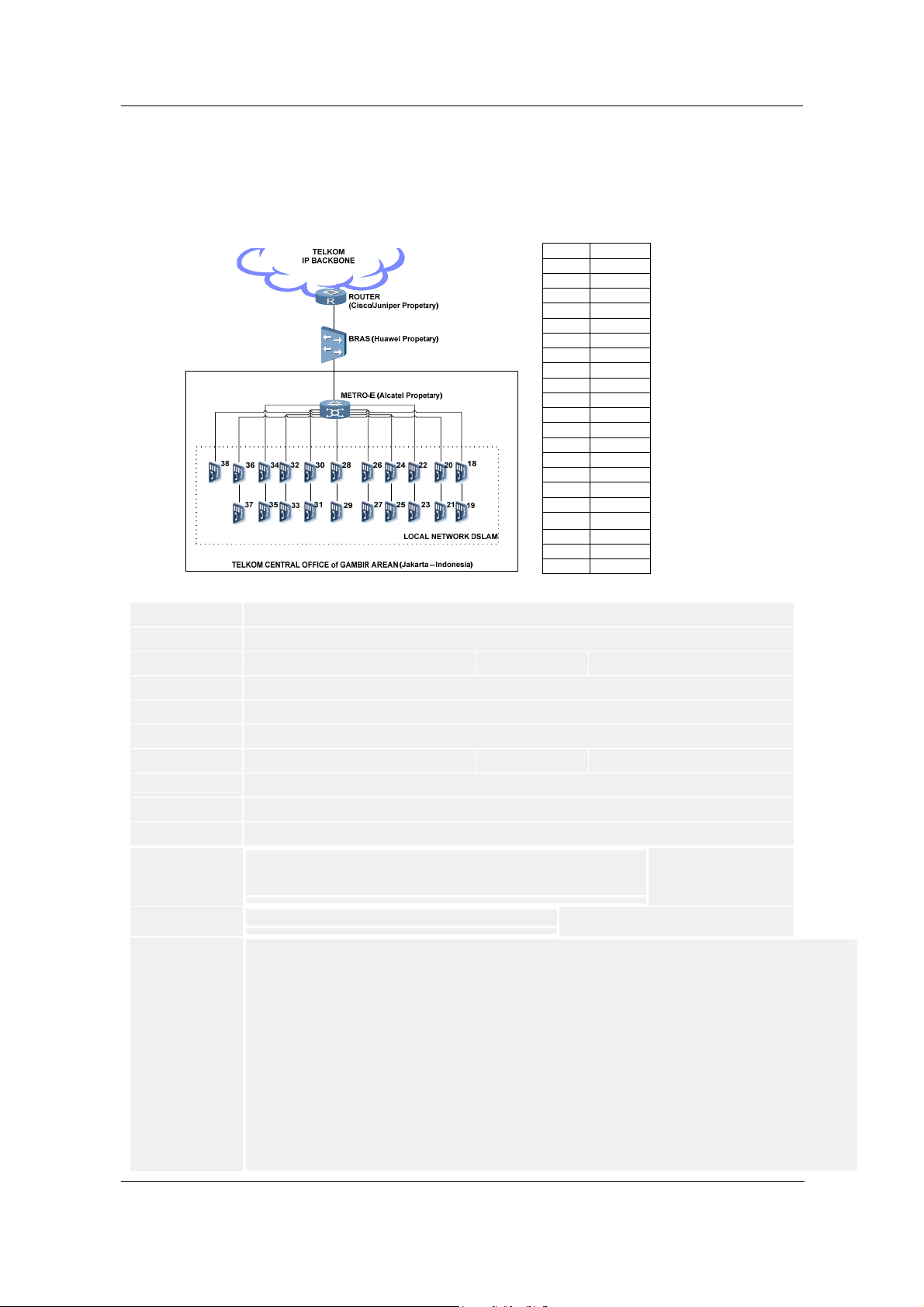
NGN Cases Chapter 1 MA5600 Cases
1.12 Conflict mac-address also can not manage dslam from inbound management
Mac Address (Case Topology)
IP of DSLAMDSLAM
10.12.24.5318
10.12.24.5419
10.12.24.5520
10.12.24.5621
10.12.24.5722
10.12.24.5823
10.12.24.5924
10.12.24.6025
10.12.24.6126
10.12.24.6227
10.12.24.6328
10.12.24.6429
10.12.24.6530
10.12.24.6631
10.12.24.6732
10.12.24.6833
10.12.24.6934
10.12.24.7035
10.12.24.7136
10.12.24.7237
10.12.24.7338
Title: Conflict mac-address also can not manage dslam from inbound management
ID: SE0000365895
Information Type :
Troubleshooting Cases
Update Time: 2008-12-31 18:44:55
Views: 19
Author: Kores F B Sinaga - 00713498
Product Family:
Fault Type:
Broadband Access
Host/Network Management System (independent from service)
Keywords: mac-address conflict inbound management
Permission Level: 03Equipment Users Permission
Phenomenon Descr
Alarm Informatio
Cause Analysis:
Can not manage DSLAM33 and DSLAM 34 from Inbound-NMS network.
iption:
Also found conflict mac-address both of DSLAM34 and BRAS.
(You can the topology case in the attachments bellow)
Null --> No Alarm, (These not impacted to The Service)
n:
Found MAC ADDRESS CONFLICT BETWEEN DSLAM33, DSLAM34, AND BRAS.
A.Check All DSLAM on site, Local DSLAM (Telkom Central Office of Gambir Area)
B.Can not reach (Ping and Telnet) DSLAM34 from Inbound-NMS, The Interface VLAN Management was down.
C.Found DSLAM34 mac-address used in DSLAM33 Mac-Address.
C.1.Check Mac-Address of Interface VLAN Management firstly
both of DSLAM33 and DSLAM34.
C.2.Found VLAN Management Interface of DSLAM34 Down,
even the physical interface up, service running normally, and also
already delete and recreate vlan management interface of DSLAM34.
Use with these command bellow :
DSLAM33-D2-GBR(config)#display arp all
IP Address MAC Address VLAN ID Port Type
10.12.24.69 00e0-fc84-a76e 26 0 /7 /0 Dynamic >> DSLAM 34
.........
10.12.24.1 00e0-fc84-a76e 26 0 /7 /0 Dynamic >> BRAS
DSLAM34-D2-GBR(config)#display interface vlanif 26
Quality Level:
Product:
C
SmartAX MA5600
14
Confidential Information of Huawei. No Spreading without Permission
Page 20

MSAN UA5000 Cases Chapter 1 MA5600 Cases
a
w
vlanif26 current state : DOWN
Line protocol current state : DOWN
Description : HUAWEI, MA5600 Series, vlanif26 Interface
The Maximum Transmit Unit is 1500 bytes
Internet Address is 10.12.24.69/24
IP Sending Frames' Format is PKTFMT_ETHNT_2, Hardware address is 0018-8243-035a
DSLAM32-D2-GBR(config)#display arp all
IP Address MAC Address VLAN ID Port Type
10.12.24.69 00e0-fc84-a76e 26 0 /7 /0 Dynamic >> DSLAM 34
….
10.12.24.68 0018-8243-035a 26 0 /7 /1 Dynamic >> DSLAM 33
10.12.24.1 00e0-fc84-a76e 26 0 /7 /0 Dynamic >> BRAS
D.Mac-address conflict both of DSLAM34 and BRAS.
Handling Proces
A.Check All DSLAM on site, Local DSLAM
s:
(Telkom Central Office of Gambir Area - Jakarta - Indonesia)
B.Make sure that DSLAM34 already have same Mac Address
for both of Current and Default.
B.1.Example command to show the state :
DSLAM34-D2-GBR(diagnose)%%display sysman mac-address
Current MAC address of active mainboard: 0018-8243-0357
Default MAC address of active mainboard: 0018-8243-0357
B.2.If found difference mac-address, please restore it,
with these sample below :
MA5600(config)#diagnose
MA5600(diagnose)%%display sysman mac-address
Current MAC address of active mainboard: 00e0-fc5d-bc87
Default MAC address of active mainboard: 00e0-fc5e-a149
MA5600(diagnose)%%sysman mac-address current 00e0-fc5e- a149
Modifying current MAC address may cause the conflict of MAC
address, are you
sure?(y/n) [n]:y
Command is being executed, please wait...
The configuration takes effect after system is restarted
(After System restart)
MA5600(diagnose)%% display sysman mac-address
Current MAC address of active mainboard: 00e0-fc5e-a149
Default MAC address of active mainboard: 00e0-fc5e-a149
(Note : Please due the step with used “hwmusa”)
C.Make sure that DSLAM33 already have the same Mac Address
for both of Current and Default.
C.1.Found difference mac-address for both of current and default,
also found mac-address DSLAM34 used in Vlanif26 DSLAM33,
as you can seen with these state bellow :
Use with these command bellow :
DSLAM33-D2-GBR(config)#display interface vlanif 26
vlanif26 current state : UP
Line protocol current state : UP
Description : HUAWEI, MA5600 Series, vlanif26 Interface
The Maximum Transmit Unit is 1500 bytes
Internet Address is 10.12.24.68/24
IP Sending Frames' Format is PKTFMT_ETHNT_2, Hardware address is 0018-8243-035a
DSLAM33-D2-GBR(diagnose)%%display sysman mac-address
Current MAC address of active mainboard: 0018-8243-0357
Default MAC address of active mainboard: 0018-8243-001e
D.Delete Interface Vlan Management (Vlanif26) in DSLAM33.
E.Restore Current to Default mac-address in DSLAM33.
Use with these command bellow :
DSLAM33-D2-GBR(diagnose)%%display sysman mac-address
Current MAC address of active mainboard: 0018-8243-001e
Default MAC address of active mainboard: 0018-8243-001e
F.Reboot System in DSLAM33
G.Delete VLAN MANAGEMENT (Vlanif26) in DSLAM34
H.Recreate VLAN MANAGEMENT (Vlanif26) in DSLAM34.
I.Create VLAN MANAGEMENT (Vlanif26) in DSLAM33
after system rebooted.
(Due after DSLAM34 has done delete and recreate vlanif first).
Suggestions and
Summary:
Problem happened because of Conflict Mac-Address between DSLAM33, DSLAM34, and BRAS. Problem in Inbound Man
Next, if you found the same case, please check the local network first, and make sure that each dslam already used their o
Confidential Information of Huawei. No Spreading without Permission
15
Page 21

NGN Cases Chapter 1 MA5600 Cases
1.13 Why is the Multicast Service Unstable After the MA5600 Enables the CAC Function
Title: Why is the Multicast Service Unstable After the MA5600 Enables the CAC Function
ID: SE0000367917
Information Type :
Troubleshooting Cases
Update Time: 2008-12-31 18:38:42
Views: 13
Author: w64795
Product Family:
Fault Type:
Broadband Access
BTV Service
Keywords: CAC
Permission Level: 03Equipment Users Permission
Phenomenon Descr
When the Set Top Box (STB) is connected to the ADSL service port of the MA5600, it is found that
iption:
the multicast service is unstable. After running the igmp bandwidthCAC disable command, you can
solve the problem. Why?
Alarm Informatio
Cause Analysis:
Null
n:
BandwidthCAC---multicast bandwidth check, when it is set to disable, the bandwidth check is not
performed. Be default, it is set to enable on the MA5600.
The multicast bandwidth check is classified into the check on the uplink port bandwidth and the
check on the user side bandwidth. Simply speaking, when the bandwidthCAC function is enabled,
check the uplink port bandwidth: compare the bandwidth allocated to the uplink port with the
bandwidth to be used by the uplink port program. If the former bandwidth is larger, you can order
the program. Otherwise, you cannot order the program.
Check the user side bandwidth: Compare the bandwidth allocated to the user with the bandwidth to
be used by the user. If the former bandwidth is larger, you can order the program. Otherwise, you
cannot order the program.
The bandwidth allocated to the uplink port is the product of the uplink port bandwidth and the
percentage of the bandwidth allocated to the multicast.
The bandwidth to be used by the uplink port program is the bandwidth sum of the programs bound
to the uplink port.
The bandwidth allocated to the user is the product of the downstream rate of the user port and the
percentage of the bandwidth allocated to the multicast user.
The bandwidth to be used by the user is the bandwidth sum of all the programs ordered by the user.
This is the reason that you can solve the problem by modifying the program bandwidth.
Handling Proces
igmp bandwidthCAC { enable | disable }
s:
This command is used to enable or disable the multicast Connection Admission Control (CAC) of
the uplink port and the user port, which is called the bandwidth management function. When you
need to restrict the bandwidth on the uplink port and the user port for the multicast program, you
can run this command to enable this function. After the bandwidth management function is enabled,
the bandwidth restriction on the uplink port takes effect immediately. The bandwidth restriction on
the user port takes effect when you order the program the next time. After the multicast CAC
function is disabled, the multicast bandwidth management is not performed for the uplink port and
the user port. The system does not guarantee the bandwidth of the multicast program.
When the CAC function is enabled:
1. Check the maximum multicast bandwidth that is allowed by the service port for passing.
2. Query the bandwidth of the program that is being played by the service port. 3. If the band width
of the required program is larger than the remaining allowed bandwidth of the service port, you
cannot order the program. Otherwise, you can order the program.
When the CAC function is disabled:
1. Check the maximum multicast bandwidth that is allowed by the service port for passing.
2. Query the bandwidth of the program that is being played by the service port. 3. If the band width
Quality Level:
Product:
C
SmartAX MA5600
16
Confidential Information of Huawei. No Spreading without Permission
Page 22

MSAN UA5000 Cases Chapter 1 MA5600 Cases
of the required program is larger than the remaining allowed bandwidth of the service port, you can
order the program. If the allowed bandwidth of the service port is insufficient, the packet loss
occurs. In this case, the multicast service is unstable.
Suggestions and
Summary:
The program bandwidth is statically configured when the multicast program is added. For the actual
IPTV service application, the program rate of the multicast source of the carrier should be
invariable. When configuring the multicast program on the MA5600, ensure that the program
bandwidth is configured the same as the bit rate of the program source of this program. In this way,
the bandwidth check can be effective.
The main purpose of the bandwidth check is to check and ensure that the total bandwidth occupied
by the program of the uplink port/user port does not exceed the rate actually supported by the uplink
port/user port (otherwise, the packet loss occurs). If you can ensure on the networking that the total
bandwidth occupied by the program of the uplink port/user port does not exceed the rate actually
supported by the uplink port/user port, you can disable the bandwidth check.
1.14 FAQ-How Does the MA5600 Support Anti DoS Attack Function
Title:
FAQ-How Does the MA5600 Support Anti DoS Attack Function
ID: SE0000352528
Information
Product Family: Broadband Access Product: SmartAX MA5600
Fault Type: Virus/Attack
Keywords: DOS MA5600
Permission Level: Warranty Users Permission
Phenomenon Descr
Alarm Informatio
Cause Analysis:
Handling Proces
Troubleshooting Cases Quality Level:
Type :
Q:
iption:
How does the MA5600 support the anti DoS attack function?
Null
n:
Null
A:
s:
The anti Dos attack in the MA5600 is a function that the system detects whether the DoS attack
occurs with the physical port as a granularity for xDSL boards.
The principle:
After the security anti-dos enable command is executed to enable the anti Dos attack function
successfully, the system limits the rate of sending the packets to the CPU of each service board
to 20 pps.
Meanwhile, the packets sent to the CPU of each service board are detected once every five
seconds, and the detection is performed four times consecutively. Every time the rate detected
exceeds 20 pps, it is regarded that the DoS attack occurs.
Then, the port sending the packets is added to the DoS blacklist, and an alarm is generated.
The MA5600 system does not change the status of the port added to the blacklist, but prohibits
the port from sending the packets to the CPU of the service board. Other service packets,
however, can be forwarded (the forwarding is performed by each service board). Meanwhile, the
system starts a timer with the duration of 180s. When the timer times out, which means that
B
Confidential Information of Huawei. No Spreading without Permission
17
Page 23

NGN Cases Chapter 1 MA5600 Cases
within 180s, no DoS attack occurs (To CPU packet <= 20pps), the port will be removed from the
blacklist and the restriction will be released. In addition, a recovery alarm is generated.
Suggestions and
Summary:
(1) The system can prevent the subscribers from implementing the DoS attack by using various
types of control packet, including the PPPoE discover, DHCP, ARP, ICMP, IGMP, PPP LCP
and BPDU packets.
(2) The system supports up to 1024 items in the DoS attack blacklist.
(3) When the DoS attack occurs, the system will generate an alarm within 20s.
(4) For MA5600V300R003/V300R002, the anti DoS attack function is enabled in the same way.
(5) The system generates an alarm when a DoS attack occurs or disappears.
display alarm list from 0x29000008 to 0x29000009
---------------------------------------------------------
ALARMID OUTPUT STATISTIC ALARM_NAME
---------------------------------------------------------
0x29000008 YES NO DOS attack appears
0x29000009 YES NO DOS attack disappears
---------------------------------------------------------
1.15 FAQ-Precautions for Modifying the ADSL Line Profile of the MA5600
Title:
FAQ-Precautions for Modifying the ADSL Line Profile of the MA5600
ID: SE0000383784
Information
Product Family: Broadband Access Product: SmartAX MA5600
Fault Type: ADSL Access Service
Keywords: Line profile, take effect, line-profile modify
Permission Level: 03Equipment Users Permission
Phenomenon Descr
Alarm Informatio
Cause Analysis:
Handling Proces
Suggestions and
Summary:
Troubleshooting Cases Quality Level:
Type :
Q:
iption:
What are the precautions for modifying the ADSL line profile of the MA5600?
Null
n:
Null
A:
s:
1. Run the adsl line-profile modify command to modify the ADSL line profile of the MA5100 or
MA5300. After the modification, the system displays the message "Do you want to make it
effect?(y/n) [n]:". If you enter N, the modified line profile takes effect after the ports are
activated next time. If you enter Y, the system immediately resets all the ADSL ports that
reference the line profile to validate the modified profile.
2. Run the adsl line-profile modify command to modify the ADSL line profile of the MA5600.
After the modification, the system displays the message "Modify profile x successfully, and new
setting is taking effect now." Then, the system immediately resets all the ADSL ports that
reference the line profile to validate the modified profile.
Run the adsl line-profile modify command to modify the ADSL line profile of the MA5600.
After the modification, the system immediately resets all the ADSL ports that reference the line
profile to validate the modified profile.
It is recommended that this operation be performed when the traffic is small to minimize the
effect.
C
18
Confidential Information of Huawei. No Spreading without Permission
Page 24

MSAN UA5000 Cases Chapter 1 MA5600 Cases
1.16 FAQ-How to Solve the Problem That the MA5600 is Enabled with Anti-MACspoofing
So That the Hot-Spot Service in the Modem with the Fixed IP Address is Interrupted
Title:
FAQ-How to Solve the Problem That the MA5600 is Enabled with Anti-MACspoofing So
That the Hot-Spot Service in the Modem with the Fixed IP Address is Interrupted
ID: SE0000369730
Information
Troubleshooting Cases Quality Level:
Type :
C
Product Family: Broadband Access Product: SmartAX MA5600
Fault Type: Others
Keywords: MA5600, MAC spoofing, fixed IP hot-spot
Permission Level: 04Common Users Permission
Phenomenon Descr
iption:
Host version: MA5600 V300R003C02B068Networking: Broadband access ADSL2+, triple
play, and IPoA services
Hotspot: clients-->wirelessAP-->Modem-->MA5600-->upper layer network
Fault phenomenon: The customer complains that the port can be activated but the connected
hotspot access service fails.
Alarm Informatio
Cause Analysis:
Null
n:
The problem of activation success but access failure involves the entire shelf. In addition, it is
confirmed that multiple sites have the similar problems. The involved service is single (hotspot).
At the time, the customer tries to enable anti-MACspoofing, which causes the special service
disconnection. Therefore, the hardware or system fault is excluded. The possible cause is that the
terminal device is incompatible with the system configuration.
Handling Proces
1. After a query, it is found that the port is in activated status and passes atm-ping. It indicates
s:
that the channel between the CPE and the board is smooth.
2. Query the MAC address learnt by the port. It is found that no MAC address is obtained. The
wireless AP problem is excluded.
3. After the MACspoofing is disabled, the service is in the normal state. The port can learn the
MAC address. The problem focuses on why the CPE cannot send the packets with the MAC
address in the normal state.
4. It is found that other IPoA users configured with the static IP addresses are not affected.
According to query, the MAC addresses can be obtained but are assigned by the system MAC
address pool.
5. Add the MAC address of the modem manually to the system. The problem is solved.
6. It is confirmed that the problem is caused by the terminal modem, which is configured with
the static IP address. In this case, there is no DHCP/ARP interaction, and the authentication
mode is not PPPoE/A. Therefore, the MA5600 cannot obtain the IP address.
Suggestions and
Summary:
After anti-MACspoofing is enabled, the mechanism for the MA5600 to learn the MAC addresses
changes, which is that passively wait for the port to interconnect the modem and the MAC
address is intercepted from the PPPoE/A,DHCP/ARP packets. The problems occ ur in this case
mostly because the port cannot obtain the MAC address. The disable MACspoofing MAC
function is obtained by the service board negotiating with the modem through the inAtmArp
protocol. Therefore, this problem does not occur. In addition, the services to which the system
uses the MAC pool to assign the MAC address type of the port are not affected, such as IPoA
services.
Confidential Information of Huawei. No Spreading without Permission
19
Page 25

NGN Cases Chapter 1 MA5600 Cases
A
A
e
1.17 FAQ-how to judge what is the problem about ADSL line quality
FAQ-how to judge what is the problem about ADSL line quality
SE0000396417
Troubleshooting Cases
Broadband Access
Quality Level:
Product:
C
SmartAX MA5600
DSL Access Service
DSL line quality
01Huawei Engineers Permission
Q:
there are many problem is caused by ADSL line quality ,but how can we judge it and fix it ?
Null
Null
A:
1. check whether the line is too long or not.
according the attenuation in down stream, if the attenuation in downstream is over 40dB, it means the length of the line is overrun about 4km, and it is hard to activ
2. check the line quality .
if the attenuation in upstream is large that it in downstream, it means there is a probelm about line quality , and it need the customer to check the line .
3. check the disturbing by external factor.
check the SNR parameter. if it changes in a large range, and it becomes to negative in sometimes. we can confirm there is disturbing by external factor.
4. check the line collocation at the user's home.
check the bit allocation from MA5600, if there is sunken in the bit allocation, it means there is a problem in the filter or the phone in the subscriber side.
Null
1.18 FAQ-How to recover admin password in MA5600
Title: FAQ-How to recover admin password in MA5600
ID: SE0000380843
Information Type :
Update Time: 2009-03-20 09:42:13
Author: Ma Ming
Product Family:
Fault Type:
Keywords: MA5600 root admin password
Permission Level: 03Equipment Users Permission
Phenomenon Descr
20
Troubleshooting Cases
Views: 34
Broadband Access
Others
Q:
iption:
How to recover admin password of root user in MA5600?
Confidential Information of Huawei. No Spreading without Permission
Quality Level:
Product:
C
SmartAX MA5600
Page 26

MSAN UA5000 Cases Chapter 1 MA5600 Cases
g
d
m
d
Alarm Informatio
Cause Analysis:
Handling Proces
Null.
n:
Null.
A:
s:
in MA5600 V300R002 series version, we have supper account to modify. but in MA5600 V300R003 series version, if we for
1.19 FAQ - How can you avoid dial-in delay while using PPPoE+
Title: FAQ - How can you avoid dial-in delay while using PPPoE+
ID: SE0000371604
Information Type :
Troubleshooting Cases
Quality Level:
C
Update Time: 2009-02-28 10:25:42
Views: 9
Author: A.Rahman Alaa
Product Family:
Broadband Access
Product:
SmartAX MA5600
Fault Type:
Keywords: PITP Dial in Delay
Permission Level: 03Equipment Users Permission
Phenomenon Descr
Alarm Informatio
Cause Analysis:
Handling Proces
Q: How you can avoid dial-in delay while using PPPoE+?
iption:
Null
n:
Null
A: While using PPPoE encapsulation method for ADSL users and enabling PITP for their security and to prevent user roami
s:
PADO and PADS respectively; the DSLAM removes these tags to forward PADO and PADS to CPE which results as short
LCP packet and dial in process will completed successfully.
To avoid this delay; we have two solutions:
1 - On BRAS: let the BRAS wait a delay before sending the LCP cfgreq i.e.,increase the LCP delay by using the below co
ppp delay-lcp-negotiation.
2 - On DSLAM: Configure PITP mode as V-mode (VBAS) instead of P-mode (PPPoE+) where in V-mode no tags are adde
Refer to attached file for PITP P-Mode and V-mode dial-in processes
1.20 FAQ-How to Solve the Problem That the Entire Shelf Fail to Go Online Due to the
MA5600 Upstream Fiber Problem
Title:
ID: SE0000369685
Information Type :
Troubleshooting Cases
Update Time: 2009-01-13 09:20:26
Views: 9
Author: s00705665
Product Family:
Fault Type:
Broadband Access
Others
Keywords: MA5600, fail to go online, upstream fiber
Permission Level: 04Common Users Permission
Phenomenon Descr
Host version: MA5600 V300R003C02B068
Confidential Information of Huawei. No Spreading without Permission
Quality Level:
Product:
C
SmartAX MA5600
21
Page 27

NGN Cases Chapter 1 MA5600 Cases
iption:
Networking: DSLAM broadband access ADSL2+ and triple play services
Fault phenomenon: The customer complains that a large number of ports in a site fail to go online.
The ports, however, can be activated.
Alarm Informatio
Cause Analysis:
Handling Proces
Suggestions and
Summary:
Null
n:
The modem can be activated but a large area of the entire shelf fails to go online or goes online
very slowly. The main possible causes are as follows:
1. The backplane or the service board cannot communicate with the control board (upstream) in the
normal state.
2. The profile configuration is incorrect and the line has interference.
3. A virus occurs in the MAC or IP address spoofing.
4. The upstream daughter board, fiber line, or interconnection switch of the MA5600 is faulty.
Complaint process: The customer receives occasional complaints against the failure to go online.
s:
After a checking, it is found that the port is in the normal state and the modem can be activated for a
successful access. The complaints, however, persist. After the port is performed with migration
(replacing the slot), the complaints persist. After a week, the number of complaints increases. The
customer requires Huawei to assist in the investigation. The initial complaints against the port
activation failure cause great trouble to identify the problem. Subsequently, it is confirmed that the
port can be activated successfully. The problem is identified as follows:
1. After the service runs on the existing network for a while, no hardware alarm is reported. The
problem lies in the entire shelf. Multiple service boards are replaced. The hardware problem is
excluded.
2. The line profile configuration complies with the line profile configuration in other sites of the
existing network by trying the interleaved mode. Then, the problem is not solved. The loopback and
the afe atm-ping are in the normal state.
3. Enable the anti IP address spoofing and anti MAC address spoofing functions for the host, and
there is no record in the security blacklist.
4. Consult the upstream peer switch, and there is no ecrc error or other error code record. The
PPPoE authentication and access are smoothly successful.
5. Connect the PC and the modem to the MA5600. The DHCP, DNS, and PPPoE packets are
captured completely. The web site cannot be opened. After the optical module is replaced, the fault
persists. After the customer replaces the interconnected switch port, the fault still persists. Use the
special fiber detector to find that the RX is normal and the error code rate of the TX lower layer is
relatively high. After the fiber is replaced, the problem is solved.
For the existing network problem, you need to identify the affected range of the single port, multiple
ports, board, cross-boards, and entire shelf, and then identify the problem from software to
hardware. If the protocol is in the normal state, identify the problem at the lower layer. For example,
the fiber error code may not be displayed by capturing the ethereal packets.
1.21 FAQ-Is the 32-Channel Service Board Slot Compatible with the 64-Channel Service
Board on the MA5600
FAQ-Is the 32-Channel Service Board Slot Compatible with the 64-Channel Service Board on
Title:
the MA5600
ID: SE0000374651
Information Type :
Troubleshooting Cases
Update Time: 2009-02-09 09:13:56
Views: 16
Author: z93854
22
Confidential Information of Huawei. No Spreading without Permission
Quality Level:
C
Page 28

MSAN UA5000 Cases Chapter 1 MA5600 Cases
Product Family:
Fault Type:
Broadband Access
Backplane/Board Hardware
Product:
SmartAX MA5600
Keywords: 32-channel
Permission Level: 04Common Users Permission
Phenomenon Descr
Q:
iption:
Is the 32-channel service board slot compatible with the 64-channel service board on the MA5600?
Alarm Informatio
Cause Analysis:
Handling Proces
Null
n:
Null
A:
s:
The heat generated by the 64-channel service board is more than that of the 32-channel service
board, so the power of the fan tray for the 32-channel service board cannot meet the requirements
on the heat dissipation of the 64-channel service board. If the 64-channel service board is installed
in the slot for the 32-channel service board, the 64-channel service board may be faulty. Therefore,
the 32-channel service board is not slot compatible with the 64-channel service board.
Suggestions and
Summary:
The BOM of the fan for the newly delivered shelf is 32030010.
1.22 FAQ-How to Connect and Configure the Humidity Sensor in the H304ESC
Title: FAQ-How to Connect and Configure the Humidity Sensor in the H304ESC
ID: SE0000356394
Information Type :
Troubleshooting Cases
Update Time: 2008-11-10 17:12:42
Views: 16
Author: w56146
Product Family:
Fault Type:
Broadband Access
Power System
Keywords: H304ESC, Humidity sensor
Permission Level: 04Common Users Permission
Phenomenon Descr
Alarm Informatio
Cause Analysis:
Handling Proces
Q:
iption:
How to connect and configure the humidify sensor in the H304ESC?
None
n:
None
A:
s:
As for hardware connection, the H304ESC provides many JTD interfaces and JTA interface.
Where, the JTD interface is used for connecting the digital parameter sensor, and the JTA interface
is used for connecting the analog parameter sensor.
In general, the humidity sensor is an analog parameter sensor. Therefore, it can be connected to
the JTA2 interface.
As for software configuration, see the Command Reference of the corresponding device. The
following shows an example of the command.
huawei(config-if-h304esc-0)#esc analog 6 40 80 0 100 sersor-type :1current unit H name
RoomHumidity
Quality Level:
Product:
B
SmartAX MA5600
Confidential Information of Huawei. No Spreading without Permission
23
Page 29

NGN Cases Chapter 1 MA5600 Cases
n
e
h
h
For how to select the analog parameter ID when running this command, see the Command
Reference of the corresponding device. For example, the Command Reference of the MA5600
provides the following description:
0: is the default inner analog parameter fixedly allocated to the temperature sensor by the system
and cannot be modified by the user.
1-4: are allocated to the voltage sensor by default.
1 indicates number 0 -48 V input.
2 indicates the first -48 V input.
3 indicates the second -48 V input.
4 indicates the third -48 V input.
5-8: are user-defined analog parameters for allocating to other extended analog sensors, such as
humidity sensor.
More information:
1. The H303ESC has a built-in humidity sensor. The built-in sensor is located in J5 of the board and
its analog parameter ID is 2. The H303ESC can also be connected to an external humidify sensor
and the connection and configuration methods are the same as what the preceding describes.
Without the built-in humidity sensor, the H304ESC is a simplified H303ESC and must be connected
to an external one.
2. The differences between the H304ESC and the H303ESC are that the LED of the H303ESC is
red and the LED of the H304ESC is green.
1.23 FAQ- Why configurations are lost when using save configuration command
Title: FAQ- Why configurations are lost when using save configuration command
ID: SE0000364112
Information Type :
Troubleshooting Cases
Update Time: 2008-12-23 10:44:56
Views: 16
Author: A.Rahman Alaa
Product Family:
Fault Type:
Broadband Access
Others
Keywords: Save configuration
Permission Level: 03Equipment Users Permission
Phenomenon Descr
Alarm Informatio
Cause Analysis:
Handling Proces
Q:
iption:
why configurations are lost when using "save configuration " command at SmartAX MA5600?
Null.
n:
Null.
A :
s:
After entering this command and resetting the DSLAM; all configuration will be lost where the DSLAM will not consider the
Active configuration
"Save Configuration" command is used to save the current system configuration file. When you need to save the configurati
Suggestions and
Summary:
1- The configurated data is saved in the configuration file in the command line form, including the data type, value of param
2 - Before the progress for saving is complete, do not power off or reset the system by force. Otherwise the data saved in t
3 - Run the "active configuration" command to activate the saved configuration file. The configuration file takes effect after t
4 - Run the "display current-configuration" command to query the configuration information.
Quality Level:
Product:
C
SmartAX MA5600
24
Confidential Information of Huawei. No Spreading without Permission
Page 30

MSAN UA5000 Cases Chapter 2 MA5600T (IP DSLAM) Cases
u
d
Chapter 2 MA5600T (IP DSLAM) Cases
2.1 Failure to save data after recover a data from Data Center
Failure to save data after recover a data from Data Center
Title:
ID: SE0000375219
Information
Type :
Update Time: 2009-03-06 11:24:28
Views: 10
Author: 79197Jose Maria Maestre
Product Family:
Fault Type:
Keywords: Failure to save data after load a backup from Data Center
Permission
Phenomenon De
scription:
Alarm Informatio
Cause Analysi
Handling Proces
Suggestions and
Summary:
Troubleshooting Cases Quality Level:
Broadband Access
Other
03Equipment Users Permission
Level:
We have found some DSLAM that after make a change in the configuration and after that try to save the chan
AFTER A "SAVE" COMMAND :
n:
Already load configuration data, needn't save data,
please execute the system reset command
----------------------------------------------------Active board data has been erased, forbid data saving now
Please reboot the board to recover the blank database
After a "load data" file from tfpt , xmodem or ftp , if not reboot the DSLAM you can not save any new changes
s:
The same happens after "erase flash data". If DLSAM in this circumstances are rebooted or lost the power s
1 -LOCATE DSLAMS AFFECTED
s:
The way to discover DSLAM's with this problem on real network is checking the backups and the changes on
2-SOLVE THE PROBLEM
It is needed save the configuration with "save configuration" command to ensure all the data will be maintaine
After this when DSLAM recovers will maintain the changes.
Null
Product:
C
MA5600T MSAN
2.2 Abnormal PADT Packet Attack interrupting access users to dialup
Abnormal PADT Packet Attack interrupting access users to dialup
Title:
ID: SE0000371995
Information
Type :
Update Time: 2009-02-06 11:18:30
Views: 7
Author: Ken Wu
Product Family:
Fault Type:
Keywords: Broadcast
Troubleshooting Cases Quality Level:
Broadband Access
Product:
C
MA5600T MSAN
ADSL Access Service
Confidential Information of Huawei. No Spreading without Permission
25
Page 31

NGN Cases Chapter 2 MA5600T (IP DSLAM) Cases
D
Permission
Phenomenon De
scription:
04Common Users Permission
Level:
The topology is as following:
MA5600T--->CX300------>Cx600-->BRAS
Broadband version:V800R005B118
SIP version:V800R006C31B031
We have discovered many abnormal PADT packet attack generates a broadcast storm, the CPU usage is run
Alarm Informatio
Cause Analysi
Handling Proces
Suggestions and
Summary:
We can tell the status of GICD card from MA5600T is very busy blinking all the time.
n:
The packets are captured onsite and after analysing the packets. We discovered a large amount of abnor mal
s:
We filtered the packets on CX300 according to the souce MAC address of the abnormal broadc ast storm PA
s:
A patch to allow the DSLAM to identify and filter rogue PADT packets was developed and loaded on every sin
2.3 Interruption of the BTV Service at an Interval of About 5 Minutes Due to Deferred
Response to the General Query Packets
Interruption of the BTV Service at an Interval of About 5 Minutes Due to Deferred
Title:
Response to the General Query Packets
ID: SE0000356312
Information
Type :
Update Time: 2008-11-10 17:11:53
Views: 14
Author: l42044
Product Family:
Fault Type:
Keywords: IGMP, Interruption of the BTV service
Permission
Phenomenon De
scription:
Alarm Informatio
Cause Analysi
Handling Proces
Troubleshooting Cases Quality Level:
Broadband Access
BTV Service
04Common Users Permission
Level:
The subscriber can get online normally to watch BTV programs and the pictures are
normal. Four or five minutes later, however, the multicast video stream will be
interrupted. That is, either blank screen or service interruption occurs.
None
n:
After the program is online, the customer’s multicast server sends the IGMP V3 general
s:
query packet in 60 seconds three times. If the multicast server does not receive any
response for these three times, the multicast server considers that the multicast
subscriber is offline, and then disconnects the transmitted multicast stream, causing
service interruption.
In this case, the multicast mode of the MA5600T is IGMP proxy. Because no general
query packet responding to the multicast service is received, it can be determined that
the fault occurs on the MA5600T. To prevent this fault temporarily, we can run a
specified command to periodically send the IGMP report packet to the multicast server.
1. When the multicast service is interrupted, run the display igmp user online all
s:
command to check whether the multicast subscriber is online. It is found that the
subscriber gets offline already.
2. Capture packets on the upstream port. For the captured packets, see the attachment.
Through analysis, it is found that the customer’s multicast server sends the IGMP V3
general query packet after the program gets online, but the MA5600T does not respond.
Product:
B
MA5600T MSAN
26
Confidential Information of Huawei. No Spreading without Permission
Page 32
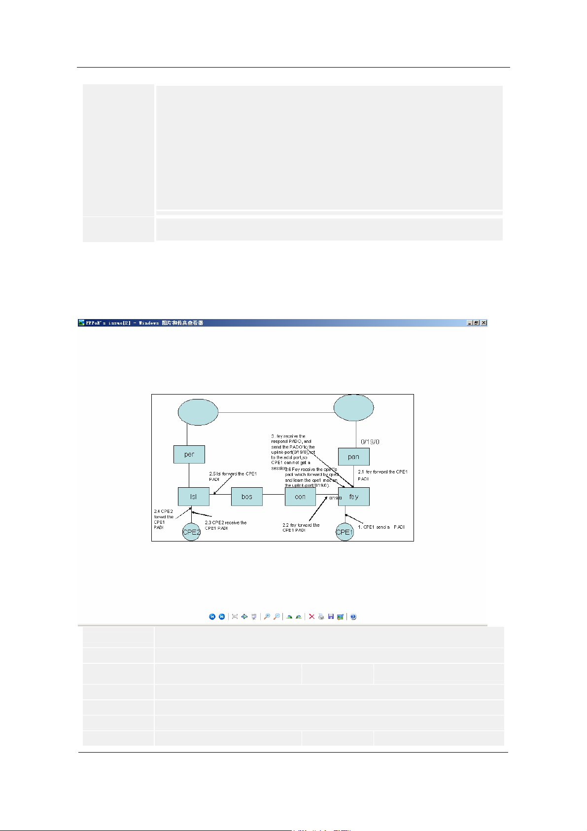
MSAN UA5000 Cases Chapter 2 MA5600T (IP DSLAM) Cases
In this case, the multicast mode of the MA5600T is IGMP proxy.
3. Because the IGMP version of the MA5600T is IGMP V2, the IGMP V3 general query
packets cannot be identified. Try to rectify this fault by modifying the IGMP version to
IGMP V3. It is found that the fault persists.
4. Through analysis, it is found that this fault can be temporarily prevented by actively
sending general query packets from the MA5600T. Run the following two command:
igmp unsolicited-report interval 30
igmp program add ip 239.255.1.2 bandwidth 15000 unsolicited enable index 1
After these two command are executed, the MA5600 sends the IGMP report packet to
the upper-layer device in each 30 seconds. Thus, this fault can be prevented
temporarily.
Suggestions and
Summary:
Capturing packets on the upstream port and then analyzing them is a basic method of
locating a fault. If we also understand protocols very well, we can locate faults quickly.
2.4 CPE under MA5600T forward PADIs from other CPE cause PPPoE user disconnected
randomly.
CPE under MA5600T forward PADIs from other CPE cause PPPoE user
Title:
disconnected randomly.
ID: SE0000308371
Information
Type :
Troubleshooting Cases Quality Level:
Update Time: 2007-12-26 13:45:41
Views: 12
Author: Chandler Young
Product Family:
Broadband Access
Confidential Information of Huawei. No Spreading without Permission
Product:
B
MA5600T MSAN
27
Page 33

NGN Cases Chapter 2 MA5600T (IP DSLAM) Cases
e
g
t
c
o
r
e
Fault Type:
Keywords: CPE PADI
Permission
Level:
Phenomenon De
scription:
Alarm Informatio
Cause Analysi
Handling Proces
Suggestions and
Summary:
ADSL Access Service
02Huawei Partners Permission
Topology: CPE ====== MA5600T ======= BAS
Version: V800R002C01B070SP01T
1. Somewhere office's network architecture is RSTP.
2. One of vlan was used to bear of PPPoE service, but sometime discover have 200 PPPoE user will disconn
3. After disconnect, the users cannot dial successfully again.
Null
n:
1. Discover the user's MAC address "0016-ce5a-7213" was learnt on uplink-port, so I elementary conclude mi
s:
2. But after checkout configuration and alarm information that overthrow my above conclusion and I use A CL
3. Therewithal we can deduce have some CPE on the user side will forward other CPE's PADI.
4. But checkout the amount of MAC address was learnt on ports is normal, that is because enabled IPTP fun
1. Use command to display system's alarm information, verify did it have topology switchover mark.
s:
display alarm history alarmtime start
2. Use ACL to capture that MAC address "0016-ce5a-7213" on the uplink-port of DSLAM. And then you can l
3. Enable anti-macspoofing function on one of DSLAM, and display the mac-bind entries.
dsl-con87-01(config)#display security bind mac
5 0017-3338-36df 0/ 6/27 901 8 35 byEncap pppoe
6 000e-9b6b-49a9 0/ 6/27 901 8 35 byEncap pppoe
8 0017-335b-9d5f 0/ 6/27 901 8 35 byEncap pppoe
9 0016-ce5a-7213 0/ 6/27 901 8 35 byEncap pppoe
10 0017-3334-ae8b 0/ 6/27 901 8 35 byEncap pppoe
14 000e-9bc9-27ef 0/ 6/27 901 8 35 byEncap pppoe
20 0017-332e-99f3 0/ 6/27 901 8 35 byEncap pppoe
32 000e-9bae-669d 0/ 6/27 901 8 35 byEncap pppoe
4. After enable anti-macspoofing function, we can find out under this port will binding 8 mac address very fast.
5. Deactivate this port, problem solved.
1. If mac address of user was learnt on uplink-port, we can figure out that might be cause by presence loop o
2.And we can use the specifically of anti-system to make certain which MAC address is legal;
such as PITP function, when PITP was enabled on our DSLAM, so based on principle of PITP function, what
t PPPOE (PADI, PADR) but still can learn in LCP negotiation phase.
2.5 On the MA5600T the line-rate of ADSL2+ port is not enough for watch t wo programs at
the same time
On the MA5600T the line-rate of ADSL2+ port is not enough for watch two
Title:
programs at the same time
ID: SE0000322136
Information
Type :
Update Time: 2008-03-29 15:51:27
Views: 15
Author: Chandler Young
Product Family:
Fault Type:
Keywords: IPTV ADSL2+
Permission
Phenomenon De
28
Troubleshooting Cases Quality Level:
Broadband Access
BTV Service
Warranty Users Permission
Level:
Topology:
Confidential Information of Huawei. No Spreading without Permission
Product:
C
MA5600T MSAN
Page 34

MSAN UA5000 Cases Chapter 2 MA5600T (IP DSLAM) Cases
b
s
M
c
/
e
k
t
B
scription:
Alarm Informatio
Cause Analysi
LAN switch ------ homegateway ------ MA5600T-----Router ------ Vod Server
The client which under a port of ADSL2+ cannot watch two programs at the same time.
null
n:
Possibly have three factors will induce is issue.
s:
1. Has been limited the maximum number of programs could be watch at this port.
2. Homegate cut off those packets concerning IGMP packets.
3. The value of BW was allocated on ADSL2+ port.
Handling Proces
1. Use "display igmp user" command to check this setting of user, we can find out the value of maximum num
s:
2. Check the configuration of homegate, we can find out there is no astrict with regard to IGMP packet, so thi
3. Use "display igmp program" to check property of programs, we can find out the BW of this program was 5
4. Use "display interface adsl 0/3/0" to check the BW that was allocated on ADSL2+ port, we can find out the
5. So the user order one of programs would occupied 5Mbit/s BW, and then the residual BW onl y have 4 Mbit
6. We modify this line-rate of ADSL2+ port to bigger, as a result user can watch multi-programs, problem solv
Suggestions and
Summary:
null
2.6 Smart AX MA5600T ACL malfunction caused by PPP&DHCP packets SCUB CPU
capturing and not processing by ACL
Smart MX MA5600T ACL malfunction caused by PPP&DHCP packets SCUB CPU
Title:
capturing and not processing by ACL
ID: SE0000348141
Information
Type :
Update Time: 2008-09-22 11:10:46
Views: 6
Author: Khanachivskyi
Product Family:
Fault Type:
Keywords: MA5600T acl PPP DHCP packets
Permission
Phenomenon De
scription:
Alarm Informatio
Cause Analysi
Troubleshooting Cases Quality Level:
Broadband Access
QACL Service
01Huawei Engineers Permission
Level:
After configuring acl that denies all the packets on inbound and outbound d irection interface still let some pac
Test scheme was the following: adsl client------MA5600T(upling GICE port 1)------cisco 3400.
Null
n:
The cause - SCUB CPU process PPP & DHCP packets before ACL function. That cause that when adsl clien
s:
ystem incorrect work and uplink lan switch will hang.
Target software versions: ma5600tv800r005c32b056, MA5600 V800R005C32B118, MA5600 V8 00R005C32
capture packets from cisco switch are attached
Kiev-Test-HW-MA5600T(config)#display acl 4555
Link ACL 4555, 1 rule
Acl's step is 5
rule 5 deny
Kiev-Test-HW-MA5600T(config)#display packet-filter
{ all<K>|port<K> }:port 0/20/1
Command:
display packet-filter port 0/20/1
port 0/20/1
Inbound:
inbound Acl 3033 rule 1 port 0/20/1 running
inbound Acl 3033 rule 5 port 0/20/1 running
Product:
C
MA5600T MSAN
Confidential Information of Huawei. No Spreading without Permission
29
Page 35

NGN Cases Chapter 2 MA5600T (IP DSLAM) Cases
g
inbound Acl 3033 rule 15 port 0/20/1 running
inbound Acl 3033 rule 20 port 0/20/1 running
inbound Acl 4555 rule 5 port 0/20/1 running
port 0/20/1
Outbound:
outbound Acl 4555 rule 5 port 0/20/1 running
Kiev-Test-HW-MA5600T(config)#display service-port port
{ frameid/slotid/portid<S><1,15> }:0/1/17
{ gemport<K>|ont<K>|<cr>|sort-by<K>|autosense<K> }:
Command:
display service-port port 0/1/17
------------------------------------------------------------------------ INDEX VLAN VLAN PORT F/ S/ P VPI VCI FLOW FLOW RX TX STATE
ID ATTR TYPE TYPE PARA
------------------------------------------------------------------------ 17 1400 common adl 0/1 /17 1 33 - - 7 10 up
30 632 common adl 0/1 /17 1 32 - - 11 12 up
43 1200 common adl 0/1 /17 1 34 - - 453 453 up
------------------------------------------------------------------------ Total : 3 (Up/Down : 3/0)
Note : F--Frame, S--Slot, P--Port, VPI indicates GEM PortID for GPON,
pri-tag indicates priority-tagged
Kiev-Test-HW-MA5600T(config)#display mac-address port 0/1/17
---------------------------------------------------------------------------- SRV-P TYPE MAC MAC TYPE F /S /P VPI VCI FLOW FLOW VLANID
INDEX TYPE PARA
---------------------------------------------------------------------------- 30 adl 000f-b058-291d dynamic 0 /1 /17 1 32 - - 632
---------------------------------------------------------------------------- Total: 1
Note : SRV-P INDEX indicates service virtual port index,
F--Frame, S--Slot, P--Port; VPI indicates GEM PortID for GPON
Kiev-Test-HW-MA5600T(config)#display mac-address vlan 632
---------------------------------------------------------------------------- SRV-P TYPE MAC MAC TYPE F /S /P VPI VCI FLOW FLOW VLANID
INDEX TYPE PARA
-----------------------------------------------------------------------------
- eth 001b-fce7-4bb3 dynamic 0 /20/1 - - - - 632
- eth 0090-1a42-b0b9 dynamic 0 /20/1 - - - - 632
- eth 044b-8080-8003 dynamic 0 /20/1 - - - - 632
- eth 0090-1a42-a4b7 dynamic 0 /20/1 - - - - 632
30 adl 000f-b058-291d dynamic 0 /1 /17 1 32 - - 632
---------------------------------------------------------------------------- Total: 5
Note : SRV-P INDEX indicates service virtual port index,
F--Frame, S--Slot, P--Port; VPI indicates GEM PortID for GPON
Kiev-Test-HW-MA5600T(config)#
Handling Proces
1. To protect MA5600T from loops on subscriber ports enable subscriber ports loop check:
s:
ring check enable
2. To deny all packets with source mac not learned on the port and enhance security enable anti-macspoofin
security anti-macspoofing enable
security anti-macspoofing max-mac-count 1
Suggestions and
Summary:
Null
30
Confidential Information of Huawei. No Spreading without Permission
Page 36

MSAN UA5000 Cases Chapter 2 MA5600T (IP DSLAM) Cases
2.7 Pause Point in the Program Caused by the Loss of the UDP Fragment in the Multicast
Service of the Smart MA5600T
Pause Point in the Program Caused by the Loss of the UDP Fragment in the
Title:
Multicast Service of the Smart MA5600T
ID: SE0000337594
Information
Type :
Update Time: 2008-07-15 17:19:22
Views: 14
Author: y69494
Product Family:
Fault Type:
Keywords: UDP fragment BTV
Permission
Phenomenon De
scription:
Alarm Informatio
Cause Analysi
Troubleshooting Cases Quality Level:
Broadband Access
BTV Service
04Common Users Permission
Level:
Version:
V800R005C32B056
Networking:
Multicast-sever------Cisco SW ------ MA5600T ------ xdsl-board ------ modem ------STB
------TV
|--------- other-produce----xdsl-board---- the same modem ------STB ----TV
Description:
The multicast service is normal, but the picture quality of the program is a little poorer
than that of the competitor and the program has pause point. In addition, the comparison
between the packets captured by the two PCs that are in the place of the two clients
shows that the third fragment of some UDP packets captured by the PC connected to
the MA5600T is discarded. See the attachment for the packet capturing file.
Null
n:
1. The packet capturing file in the feedback from the filed engineer shows that the third
s:
fragment of some UDP packets captured on the client in a certain period is discarded.
Surely, this is the cause of the pause point and what is next is to find out the location in
which this fragment is discarded.
2. Capture packets respectively in three locations of the topology:
①Capture packets on the egress port of Cisco and perform the port mirroring on the
Cisco device. Check the sequence of the packets transmitted from the upper layer
device, analyze the packets (about 10 M) captured from the Cisco router, and find that
the problem of discarded fragment does not occur. Only some multicast UDP packets
with fewer bytes are found , which is not the problem.
②Perform the egress port mirroring on our LSW. Mirror the packets that are transmitted
to the service board to the GIU port and capture packets.
MA5600T(diagnose)%%debugging lswdrv bcm-cli
BCM.0> _Mirror mode=add OutPort=8 ToPort=6
8===>This refers to the egress direction of this GE port on the LSW. The 8 GE port maps
the service board in slot 1
6===>This is to mirror the packet in the egress direction of port 8 to this GE port of the
LSW. The 6GE port maps port 0/20/0 of this uplink board.
Analyze the captured packets (14 M) of the LSW and find that only the fragments of
some two-frame packets are discarded; however, the number of discarded fragments is
very small and this problem may occur only in the case of the multicast server burst.
③Use the PC to capture packets on the modem of our service board and find that the
symptom is the same as that in the feedback. The third fragment of many multicast UDP
packets is discarded. We are sure that the fragment is discarded by either the board or
the modem.
Product:
B
MA5600T MSAN
Confidential Information of Huawei. No Spreading without Permission
31
Page 37

NGN Cases Chapter 2 MA5600T (IP DSLAM) Cases
U
3. Further check the parameters and commands related to the board and find that the
PIR value set for the traffic profile is very small. This may be the root cause of the packet
loss and the poor multicast quality:
//Configure the VCI33 VPI1 multicast service
igmp user add port 0/1/21 adsl 1 33 video 1 33 no-auth quickleave immediate
//The traffic profile of VCI33 VPI1 is rx 9 tx 15
service-port 103 vlan 401 adsl 0/1/21 vpi 1 vci 33 single-service rx-cttr 9 tx-cttr 15
//Settings of the traffic profile
traffic table ip index 9 cir 2944 cbs 96208 pir 3968 pbs 192416 priority 6 p r iority-policy
local-setting
traffic table ip index 15 cir 384 cbs 14288 pir 768 pbs 28576 priority 6 priority-policy
local-setting
The pri value of the profile in traffic-table 9 is 3968 kbps = 3968*1024 = 40 63232 bps =
507904 byte/s.
//Check on the LSW the number of frames that pass the port in the downstream direction
each second:
BCM.0> show c
……
Omitted
GRMCA.ge7 : 10,243,109 +426,416 390/s
Omitted
……
Here, 390/s is the number of frames that pass this GE port in the downstream direction
each second. If each fragment is calculated as 1410 bytes, we can figure out:
390 * 1410 byte = 549900 byte/s > 507904 byte/s. Thus, a large number of packets are
lost.
Handling Proces
It is suggested that the onsite engineer modify the settings to enlarge the traffic profile.
s:
traffic table ip index 9 cir 2944 cbs 96208 pir 4480 (recommend) pbs 192416 priority 6
priority-policy local-setting
2.8 Smart MA5600T NTP time problem caused synchronized time abnormally
Smart MA5600T NTP time problem caused synchronized time abnormally
Title:
ID: SE0000334172
Information
Type :
Update Time: 2008-06-24 15:58:38
Views: 18
Author: Oleg Khanachivskiy
Product Family:
Fault Type:
Keywords: MA5600T NTP time utc dst
Permission
Phenomenon De
scription:
Alarm Informatio
Troubleshooting Cases Quality Level:
Broadband Access
Other
04Common Users Permission
Level:
Customer Ntp server broadcasted utc time in normal form, but MA5600T device has displayed utc time which
sychronized from ntp server with -01:00, but this utc
time is difference from real utc time. All other maufactory's devices (including windows xp computers and S
synchronized time normally), except huawei MA5600T.
The soft version is V800R005C02B056.
Null
n:
Product:
C
MA5600T MSAN
32
Confidential Information of Huawei. No Spreading without Permission
Page 38

MSAN UA5000 Cases Chapter 2 MA5600T (IP DSLAM) Cases
d
g
h
Cause Analysi
Handling Proces
The fact of cause phenomenon is
s:
that computers and some other manufactory devices automatically adopt daylight saving time and MA5600T
hand for that feature.
1. Chekced that NTP server works properly
s:
2. Debug NTP service on MA5600T
MA5600T(config)# debugging ntp-service all
After analyzing debug messages, the problem was cleared:
Our device didn't automatically adopted DST, so that to solve the problem just need to add the following strin
MA5600T(config)#time dst start 3 last sun 03:00:00 end 10 last sun 04:00:00
3.Problem solved
2.9 Smart MX 5600T PPP use cannot get IP cause by BAS malfunction
Smart MX 5600T PPP use cannot get IP cause by BAS malfunction
Title:
ID: SE0000333018
Information
Type :
Update Time: 2008-06-24 11:55:34
Views: 21
Author: 88583Eduardo Rodri guez
Product Family:
Fault Type:
Keywords: PPPoE BAS
Permission
Phenomenon De
scription:
Alarm Informatio
Cause Analysi
Handling Proces
Suggestions and
Summary:
Troubleshooting Cases Quality Level:
Broadband Access
Routing Protocol
04Common Users Permission
Level:
Smart MX 5600T release: MA5600V800R003C02B108SP01.
The DSLAM's ppp subscribers on VLAN 2490 can not get IP.
Network diagram: ISP Subscribers -- Huawei DSLAM -- External BRAS.
Null
n:
1.Check the vlan traffic on the DSLAM. Command:
s:
#display statistics vlan 2490.
2.After analyzed the traffic, if we have got upstream traffic and we don't have downstream traffic.
3.Check the connectivity to BRAS: Command:
#display mac-address vlan 2490.
We should have an MAC-entry on uplink port from BRAS machine.
Example:
eth 0013-c308-fa60 dynamic 0 /19/0 - 2543 << Vlan and MAC associated on uplink port.
4.If we don't have this entry. We can locate this problem is came from BRAS/Datacom department.
After the right test on DSLAM. The ISP found the BRAS problem. They reset its interface to our DSLAM and t
s:
Null
Product:
C
MA5600T MSAN
2.10 FAQ-How to Connect and Configure the Humidity Sensor in the H304ESC
Title: FAQ-How to Connect and Configure the Humidity Sensor in the H304ESC
ID: SE0000356394
Information Type :
Troubleshooting Cases
Confidential Information of Huawei. No Spreading without Permission
Quality Level:
B
33
Page 39

NGN Cases Chapter 2 MA5600T (IP DSLAM) Cases
Update Time: 2008-11-10 17:12:42
Views: 16
Author: w56146
Product Family:
Fault Type:
Broadband Access
Power System
Keywords: H304ESC, Humidity sensor
Permission Level: 04Common Users Permission
Phenomenon Descr
Alarm Informatio
Cause Analysis:
Handling Proces
Q:
iption:
How to connect and configure the humidify sensor in the H304ESC?
None
n:
None
A:
s:
As for hardware connection, the H304ESC provides many JTD interfaces and JTA interface.
Where, the JTD interface is used for connecting the digital parameter sensor, and the JTA interface
is used for connecting the analog parameter sensor.
In general, the humidity sensor is an analog parameter sensor. Therefore, it can be connected to
the JTA2 interface.
As for software configuration, see the Command Reference of the corresponding device. The
following shows an example of the command.
huawei(config-if-h304esc-0)#esc analog 6 40 80 0 100 sersor-type :1current unit H name
RoomHumidity
For how to select the analog parameter ID when running this command, see the Command
Reference of the corresponding device. For example, the Command Reference of the MA5600
provides the following description:
0: is the default inner analog parameter fixedly allocated to the temperature sensor by the system
and cannot be modified by the user.
1-4: are allocated to the voltage sensor by default.
1 indicates number 0 -48 V input.
2 indicates the first -48 V input.
3 indicates the second -48 V input.
4 indicates the third -48 V input.
5-8: are user-defined analog parameters for allocating to other extended analog sensors, such as
humidity sensor.
More information:
1. The H303ESC has a built-in humidity sensor. The built-in sensor is located in J5 of the board and
its analog parameter ID is 2. The H303ESC can also be connected to an external humidify sensor
and the connection and configuration methods are the same as what the preceding describes.
Without the built-in humidity sensor, the H304ESC is a simplified H303ESC and must be connected
to an external one.
2. The differences between the H304ESC and the H303ESC are that the LED of the H303ESC is
red and the LED of the H304ESC is green.
Product:
SmartAX MA5600
2.11 FAQ- Why configurations are lost when using save configuration command
Title: FAQ- Why configurations are lost when using save configuration command
ID: SE0000364112
Information Type :
Troubleshooting Cases
Update Time: 2008-12-23 10:44:56
Views: 16
Author: A.Rahman Alaa
Product Family:
34
Broadband Access
Confidential Information of Huawei. No Spreading without Permission
Quality Level:
Product:
C
SmartAX MA5600
Page 40
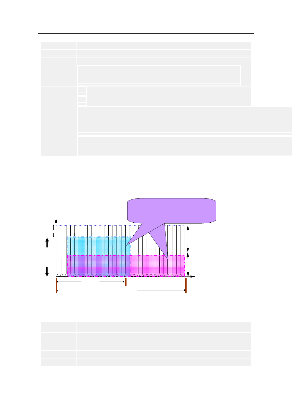
MSAN UA5000 Cases Chapter 2 MA5600T (IP DSLAM) Cases
n
e
h
h
A
Fault Type:
Keywords: Save configuration
Permission Level: 03Equipment Users Permission
Phenomenon Descr
Alarm Informatio
Cause Analysis:
Handling Proces
Suggestions and
Summary:
Others
Q:
iption:
why configurations are lost when using "save configuration " command at SmartAX MA5600?
Null.
n:
Null.
A :
s:
After entering this command and resetting the DSLAM; all configuration will be lost where the DSLAM will not consider the
Active configuration
"Save Configuration" command is used to save the current system configuration file. When you need to save the configurati
1- The configurated data is saved in the configuration file in the command line form, including the data type, value of param
2 - Before the progress for saving is complete, do not power off or reset the system by force. Otherwise the data saved in t
3 - Run the "active configuration" command to activate the saved configuration file. The configuration file takes effect after t
4 - Run the "display current-configuration" command to query the configuration information.
2.12 F AQ- why we can not get the same value of S NR margin use the same line-profile in the
same physical-line.
Rate VS SNR
Signal
¹Power
ADS L
SNR
DS L
B i t di s tri bu te
we can s ee the proportion of blue
one is equal to the red one. That
means you allocate the same linerate in ADSL and ADS L 2+.
ADS L
ADS L 2+
ADS L
256 tones
ADS L2+
512 tones
(SNR margin):Look at the area was leave over that is SNR margin
value, their areas are different in both protocol, ADSL and ADSL2+.
The area of SNR margin in ADSL2+ is bigger than ADSL's obviously.
FAQ-why we can not get the same value of SNR margin use the same line-profile in
Title:
the same physical-line.
ID: SE0000321912
Information
Type :
Update Time: 2008-03-29 15:51:47
Views: 16
Troubleshooting Cases Quality Level:
ADSL2+
noise margin
ADSL2+
bit distribute
tone
C
Confidential Information of Huawei. No Spreading without Permission
35
Page 41

NGN Cases Chapter 2 MA5600T (IP DSLAM) Cases
h
t
Author: Chandler Young
Product Family:
Fault Type:
Broadband Access
ADSL Access Service
Product:
MA5600T MSAN
Keywords: line-rate SNR
Permission
Phenomenon De
scription:
Alarm Informatio
Cause Analysi
Handling Proces
01Huawei Engineers Permission
Level:
Q:
1.When we configure (in the same line) one line profile to 6 Mega in ADSL and ADSL2+, we can vi ew that we
null
n:
null
s:
A:
s:
1.Firstly, SNR margin in order to anti cable noise when those tones bearing bit.
2. The transmit power have two purposes: one part of power would be used for providing the line rate; the ot
3. So, this phenomenon is completely normalization; because ADSL’s bandwidth just have half of adsl2+ (ads
4. If you disable ADSL2+’s tones 256 to 511, the SNR is calculated considering the same tones. It means tha
To add an extended ADSL2+ line profile and disable the tones 80–90, do as follows:
huawei(config)#adsl extline-profile add
{ <cr>|profile-index<L><1,32> }:
Command:
adsl extline-profile add
Start adding profile
Notes: If pilot tone is included in the forbidden tones, the link may not be activated
When port activated with annexA in mode G992.1, 64tone is pilot
When port activated with annexB in mode G992.1, 96tone is pilot
Press 'Q' to quit the current configuration and new configuration will be
neglected
> Do you want to name the profile (y/n) [n]:n
> Will you configure the disabled tone? (y/n)[n]:y
> How many sections do you want to configure?(1-4)[4]:1
> No.1 Please input the start index of the disabled tone(32-511)[32]:80
> Please input the end index of the disabled tone(32-511)[32]:90
> Do you want to validate the settings of this section? (y/n)[n]:y
> Will you configure the minimum INP in downstream? (y/n)[n]:
> Will you configure the minimum INP in upstream? (y/n)[n]:
> Will you configure the maximum PSD mask in downstream? (y/n)[n]:
Add profile 1 successfully
huawei(config)#display adsl extline-profile 1
----------------------------------------------------------------- Profile Index : 1 Name: ADSL EXTLINEPROFILE 1
Minimum INP in downstream(DMT Symbol) :auto
Minimum INP in upstream(DMT Symbol) :auto
Maximum PSD mask in downstream(-dBm/Hz) :40
ADSL transmission mode in standard : ADSL annex type : Current configuration of each section:
Sections Value Effective
Section 1 80 - 90 y
Section 2 0 - 0 n
Section 3 0 - 0 n
Section 4 0 - 0 n
Suggestions and
Summary:
Null
36
Confidential Information of Huawei. No Spreading without Permission
Page 42

MSAN UA5000 Cases Chapter 2 MA5600T (IP DSLAM) Cases
h
c
2.13 FAQ-What is the maximum number of line-profile and line-template that can be
defined in MA5600T
FAQ-What is the maximum number of line-profile and line-template that can be
Title:
defined in MA5600T
ID: SE0000314883
Information
Type :
Troubleshooting Cases Quality Level:
C
Update Time: 2008-01-31 11:21:25
Views: 19
Author: Sam Zahedi
Product Family:
Fault Type:
Broadband Access
VDSL Access Service
Product:
MA5600T MSAN
Keywords: line-template
Permission
Phenomenon De
scription:
04Common Users Permission
Level:
Q:
Customer wants to know the limitation of the line-profiles max number and line-template max number that can
Apparently, the value of the index assigned to each profile can be between 2 and 999 for adsl and between 2
but they need to know whether this means that the equipment even supports 998 or 128 different profiles at t
Alarm Informatio
Cause Analysi
Handling Proces
Null
n:
Null
s:
A:
s:
After confirming with R&D, we informed customer that :
1. For the VDSL2+ template, the DSLAM supports 127 profiles at most, and the number we can config is from
2. For the ADSL2+ template, the DSLAM supports 127 profiles at most, in V8R3, the number we can config is
in V800R005, the number we can config is from 2 to 128. After informing the customer we cleared the techni
Suggestions and
Summary:
Null
2.14 FAQ-How to Select the Correct Frequency Spectrum Profile During the Configuration
of the VDSL2 Line Profile
FAQ-How to Select the Correct Frequency Spectrum Profile During the
Title:
Configuration of the VDSL2 Line Profile
ID: SE0000356282
Information
Type :
Product Family:
Fault Type:
Keywords: Frequency spectrum, G.993.2, profile, and line profile
Permission
Phenomenon De
scription:
Troubleshooting Cases Quality Level:
Broadband Access
Product:
VDSL Access Service
04Common Users Permission
Level:
Q:
How to Select the correct frequency spectrum profile during the configuration of the
VDSL2 line profile?
Confidential Information of Huawei. No Spreading without Permission
C
MA5600T MSAN
37
Page 43

NGN Cases Chapter 2 MA5600T (IP DSLAM) Cases
Alarm Informatio
Cause Analysi
Handling Proces
None
n:
None
s:
A:
s:
1. The 17a and 30a profiles are used in short-haul applications (Generally the distance is
no greater than 300 m). In fact, the 30a profile is rarely used. Currently, the 17a profile is
used in short-haul applications.
2. The 12a, 12b, 8c, and 8d profiles are used in medium-haul applications (generally the
distance is from 300 m to 1 km).
The 8a and 8b profiles are used in long-haul applications (the distance is greater than 1
km). They are compatible with ADSL2 and ADSL2+, and suitable for central offices (The
8a profile can provide a transmit power of 20.5 dBm, the same as in ADSL2+.). The
coverage range can exceed 3 km and is close to the coverage range of ADSL2+.
3. When the distance is greater than 1.5 km, the rate curve of the VDSL2 overlaps with
that of the ADSL2+. In the distance from 1 km to 1.5 km, the rate advantages of the
VDSL2 are not obvious. Therefore, the main coverage range of the VDSL2 is still less
than 1 km.
4. The 12a, 17a, and 30a profiles are especially suitable for short-and-medium-haul
applications, such as FTTN, FTTC, and FTTB. Take the 12aB8-4 as an example. T he
uplink can be at least 10 Mbit/s over a copper cable whose diameter is 0.4 mm within a
distance of 500 m, 5 Mbit/s within a distance of 700 m, and 1 Mbit/s within a distance of 1
km (24 VDSL2 lines with self-crosstalk). The downlink rate can be 30 Mbit/s over a
copper cable whose diameter is 0.4 mm within a distance of 500 m, 20 Mbit/s within a
distance of 700 m, and 18 Mbit/s within a distance of 1 km (24 VDSL2 lines with
self-crosstalk). If the 17a or 30a profile is used, the rate can be 30 Mbit/s or 100 Mbit/s in
the uplink, and 50 Mbit/s or 100 Mbit/s in the downlink within a distance of 300 m.
Suggestions and
Summary:
In practical application, the profiles can be flexibly chosen. The profiles given in this case
are for reference only.
2.15 FAQ-What Is by Default the Running Mode of the Fan of the MA5606T
FAQ-What Is by Default the Running Mode of the Fan of the MA5606T
Title:
ID: SE0000355980
Information
Type :
Update Time: 2008-11-06 17:34:03
Views: 6
Author: l00104858
Product Family:
Fault Type:
Keywords: Fan, Speed Adjustment
Permission
Phenomenon De
scription:
Alarm Informatio
Cause Analysi
Handling Proces
Troubleshooting Cases Quality Level:
Broadband Access
Environment
04Common Users Permission
Level:
Q:
What is by default the running mode of the fan of the MA5606T?
Null
n:
Null
s:
A:
s:
By default, the running mode of the fan of the MA5606T is the manual adjustment mode
Product:
C
MA5600T MSAN
38
Confidential Information of Huawei. No Spreading without Permission
Page 44

MSAN UA5000 Cases Chapter 2 MA5600T (IP DSLAM) Cases
and the speed level is level 5, which is the highest level and does not vary with the
environment temperature.
Suggestions and
Summary:
Null
2.16 FAQ-How to config dynamic and static Multicas t program at MA5606T
FAQ-How to config dynamic and static Multicast program at MA5606T
Title:
ID: SE0000324269
Information
Type :
Update Time: 2008-04-22 15:06:21
Views: 13
Author: Archer
Product Family:
Fault Type:
Keywords: MA5606T dynamic static Multicast
Permission
Phenomenon De
scription:
Alarm Informatio
Cause Analysi
Handling Proces
Troubleshooting Cases Quality Level:
Broadband Access
BTV Service
01Huawei Engineers Permission
Level:
Q:
How to config dynamic and static Multicast program at MA5606T ?
Version info:MA5600 V800R005C22B056
null
n:
null
s:
A:
s:
1. If our user wants to use the dynamic order method:
#
MA5600T(config-mvlan401)#igmp match mode disable
MA5600T(config-mvlan401)#igmp match group ip
{ ip-addr<I><X.X.X.X> }:232.0.1.0
{ to-ip<K> }:to-ip
{ ip-addr<I><X.X.X.X> }:232.0.1.11
Command:
igmp match group ip 232.0.1.0 to-ip 232.0.1.11
#
2. If our user wants to use the static order method:
#
MA5600T(config-mvlan401)#igmp match mode enable
MA5600T(config-mvlan401)#igmp program add ip 232.0.1.9 index 0
#
Product:
C
MA5600T MSAN
Confidential Information of Huawei. No Spreading without Permission
39
Page 45

NGN Cases Chapter 2 MA5600T (IP DSLAM) Cases
e
t
m
c
g
o
e
h
g
Suggestions and
Summary:
1. igmp match mode
This command is used to set the program match mode based on the VLAN. When the match mode is set as
When the match mode is set as disable, multicast programs need not to be pre-configured and would automa
2. igmp match group
The igmp match group command is used to set the IP address range for the program groups that can be auto
need to restrain the IP address range for the program groups that can be automatically generated in the multi
only the programs in this address range can be automatically generated when the program is in the dynamic
3. If the superstratum device needs to check the source ip ,we need to config the hostip of program which sh
MA5600T(config-mvlan401)#igmp program add ip 232.0.1.9 hostip 10.10.10.2
2.17 FAQ-How to find out the reason for unable to call certain numbers via SIP
FAQ-How to find out the reason for unable to call certain numbers via SIP
Title:
ID: SE0000371609
Information
Type :
Troubleshooting Cases Quality Level:
C
Update Time: 2009-02-06 11:18:19
Views: 11
Author: 00705870Rajesh Naidu
Product Family:
Fault Type:
Broadband Access
Voice Quality
Product:
MA5600T MSAN
Keywords:
Permission
Phenomenon De
scription:
Alarm Informatio
Cause Analysi
Handling Proces
04Common Users Permission
Level:
Customer product:M5600T
Q:How to find out the reason for unable to call certain numbers via the MSAN 5600T ?The MSAN is configur
Null
n:
There could be 2 reasons ,
s:
1) The number being dialled has no routes in the soft switch
2) The MA5600T truncates the numbers according to the digitmap confiuration.
A:The following is the steps taken to identify the problem.
s:
1) make the call to the number that you cannot dial
2) Hear what message ( tones ) you are getting (i.e busy tone , engaged tone etc)
3) Look at the "SIP INVITE" message to see if the invite message has got all the digits that you have pressed
4) If the 'INVITE" message does not have the correct digits than the solution is described below
Suggestions and
Summary:
First of all let me explain that in a SIP environment in the MA5600T device , the dial codes are controlled by t
So in oredr to fix this issue with the customer , we noticed in the "SIP INVITE" message we were not receivin
Modify the SIP digitmap file "digitmap.efs' to include the number range
2.18 FAQ-What is difference between ADSL mode and NGADSL mode
FAQ-What is difference between ADSL mode and NGADSL mode
Title:
ID: SE0000308039
Information
Type :
Update Time: 2007-12-17 17:46:41
40
Troubleshooting Cases Quality Level:
C
Confidential Information of Huawei. No Spreading without Permission
Page 46

MSAN UA5000 Cases Chapter 3 GPON FTTx Cases
t
Views: 9
Author: HON CHEE HOCK
Product Family:
Fault Type:
Broadband Access
ADSL Access Service
Product:
MA5600T MSAN
Keywords: ADSL NGADSL
Permission
Phenomenon De
scription:
03Equipment Users Permission
Level:
Q:
MA5600T support 2 types of ADSL mode, ADSL mode and NGADSL mode.
This can be configured in diagnose mode with command "adsl mode switch-to <adsl,ngadsl>". This happen in
What is difference between ADSL mode and NGADSL mode?
Alarm Informatio
Cause Analysi
Handling Proces
Null
n:
Null
s:
A:
s:
The difference between ADSL mode and NGADSL mode is as follow:
1) ADSL mode maps RFC2662
- Configuration is consisted of a line profile only
- ADSL extended line profile can be configured based on requirement
- Up to 1002 ADSL line profile can be added for the MA5600T
- Up to 32 extended line profile can be added for the MA5600T
- ADSL port is activated with line profile index
- Extended line profile can be bond with ADSL port based on requirement
2) NGADSL mode is a new generation of ADSL standard and maps RFC4706
- Configuration is consisted line profile, channel profile and line template
- ADSL port is activated with line template index
- Up to 128 ADSL line profiles can be added for the MA5600T
- Up to 128 channel profiles can be added
- Up to 128 line template can be added
Suggestions and
Summary:
MA5600T only can be configured one ADSL mode for ADSL service configuration.
The type of ADSL mode must be selected before perform the configuration for ADSL service.
Otherwise the operation to switch between ADSL mode and NGADSL will cause all configuration of ADSL los
Chapter 3 GPON FTTx Cases
3.1 How to enable MA5680T ETHB Port to connect to other vendor's equipment
How to enable MA5680T ETHB Port to connect to other vendor's equipment
Title:
ID: SE0000385485
Information
Type :
Product Family:
Fault Type:
Keywords: MA5680T ETHB isolate
Permission
Phenomenon De
scription:
Troubleshooting Cases Quality Level:
Optical Access
Product:
Equipment Interconnection
04Common Users Permission
Level:
1.MA5680T ETHB Port can't get up when it is
Confidential Information of Huawei. No Spreading without Permission
C
MA5680T
41
Page 47

NGN Cases Chapter 3 GPON FTTx Cases
connected to packet generator tool 2.Check the patchcord, the result is OK.
3.Try loopback ETHB Port, the result is OK.
4. in this case, ETHB is in the slot 0/17.
OLT (ETHB Port 1) --> Packet generator tool (GE port)--> OLT (GICF Port 1)
Alarm Informatio
Cause Analysi
Handling Proces
Null
n:
The Board is in the isolate state
s:
In this case, ETHB is in the slot 0/17.
s:
Using command,
get into interface ETHB
#undo isolate board 0/17
Suggestions and
Summary:
Null
3.2 256 multicast channels can't be online at the same time in 5680T
256 multicast channels can't be online at the same time in 5680T
Title:
ID: SE0000385483
Information
Type :
Product Family:
Fault Type:
Troubleshooting Cases Quality Level:
Optical Access
Product:
Multicast Service
C
MA5680T
Keywords: Enable MA5680T Multicast bandwidth
Permission
Phenomenon
Descriptio
Alarm Inform
ation:
Cause Analy
sis:
Handling Pr
ocess:
04Common Users Permission
Level:
Configure MA5680T using 3 ONT (2xHG865 and 1xHG863).
When doing test, packet generator is used to generate IGMP packets as IGMP programs.
n:
The result is that only 128 multicast channels can be online at the same time.
MA5680T-->Packet generator -->HG865+HG863
Null
Check configuration of multicast but it's OK .
The conclusion is there is not enough multicast bandwidth .
MA5600T(config)#btv
MA5600T(config-btv)#igmp bandwidthcAC
{ bandwidthswitch<E><enable,disable> }:disable
Command:
igmp bandwidthcAC disable
Are you sure to disable the bandwidth management?(y/n)[n]:y
MA5600T(config-btv)#quit
MA5600T(config)#
ry:
Null
Suggestions
and Summa
42
Confidential Information of Huawei. No Spreading without Permission
Page 48

MSAN UA5000 Cases Chapter 3 GPON FTTx Cases
3.3 The Matching Status of the ONT and the Profile Is 'Mismatch' Because th e Numbers of
the GEM Ports Supported by the MA5680T and the MA562 6G Are Different
The Matching Status of the ONT and the Profile Is 'Mismatch' Because the Numbers
Title:
of the GEM Ports Supported by the MA5680T and the MA5626G Are Different
ID: SE0000383582
Information
Type :
Product Family:
Fault Type:
Troubleshooting Cases Quality Level:
Optical Access
Product:
C
MxU
Host/Network Management System (independent from service)
Keywords: GEM Port, number different, mismatch
Permission
Phenomenon De
scription:
Alarm Informatio
04Common Users Permission
Level:
After the MA5626G is added to the newly deployed MA5680T in an office, the matching
status of the optical network terminal (ONT) and the profile is always "mismatch".
LF_HM_ZhongXinJu_MA5600T(GPON)_1(config-if-gpon-0/1)#dis play ont info 0 all
n:
-----------------------------------------------------------------------------
F/S/P ONT-ID SN Control Run Config Match DBA
Flag State State State Type
-----------------------------------------------------------------------------
0/ 1/0 0 323031310B8B8842 active up normal mismatch SR
Cause Analysi
The preceding problem occurs during the actual configuration. For example, the ONT
s:
can go online and the running state is normal after the ONT is added. In this case, the
problem occurs because the actual capability set profile of the ONT is different from the
bound capability set profile or the ONT is faulty.
Handling Proces
1. The parameters in the capability profile set profiles and the device ports of the
s:
MA5680T and the MA5626G are consistent after the onsite comparison. Run the display
ont capability 0 0 command to view the parameters such as the ports and the T-CONTS
of the MA56206G and these parameters are consistent with the parameters of the
MA5680T.
2. View the MA5626G technical manual and find that the MA5626G supports up to 128
GEM ports, but the capability set profile configured on the OLT supports only 32 GEM
ports. Therefore, the parameters of the MA5626G and the OLT are inconsistent and the
matching status is "mismatch".
3. You need not pay attention to the inconsistent parameters because they do not affect
the services.
Suggestions and
Summary:
Although the parameters do not affect the services, the configuration cannot be
delivered to the ONU after the ONU is reset. Run the ont resume resource command. If
the actual ONT capability is inconsistent with the capability set profile bound to the ONT,
exclude the part in the ONT management commands that exceeds the actual hardware
capability based on hardware capability parameters reported by the ONT. In addition,
only the ONT management commands allowed by the ONT hardware capability are
delivered.
3.4 The Voice Communication on the MA5606T Is Unidirectional Because of the Routing
Problem of the Media Stream
The Voice Communication on the MA5606T Is Unidirectional Because of the
Title:
Routing Problem of the Media Stream
ID: SE0000383587
Confidential Information of Huawei. No Spreading without Permission
43
Page 49

NGN Cases Chapter 3 GPON FTTx Cases
Information
Type :
Product Family:
Fault Type:
Troubleshooting Cases Quality Level:
Optical Access
Product:
Voice Service
C
MxU
Keywords: Unidirectional, RTP, static route, MCUC
Permission
Phenomenon De
scription:
02Huawei Partners Permission
Level:
Networking: MA5606T-MA5680T-bearer network.
Version of the MA5606T: V800R005C23B052.
Fault symptom: The ringing is normal for the call-in and call-out services of the MA5606T
voice service. The communication, however, is unidirectional. That is, the user can hear
the other party but the other party cannot hear the user. The dialing between the two
internal phones of the MA5606T is normal and the preceding problem does not occur.
Alarm Informatio
Cause Analysi
Null
n:
1. The data configuration is incorrect.
s:
2. The processing of the MA5606T or the softswitch is abnormal.
3. The layer 3 route of the bearer network is faulty or certain User Datagram Protocol
(UDP) ports are shielded.
Handling Proces
1. The internal calling is normal. Through the analysis of the captured signaling packets
s:
by running the dbwin command, the signaling exchange between the MA5606T and the
softswitch is normal.
2. Replace the MA5606T with an MA5620G and ensure that all the relevant
configurations are the same. The problem does not occur during the dialing. Therefore,
the softswitch and the bearer network are normal. The problem occurs on the MA5606T.
3. View the configurations of the MA5606T. It is found that the media stream and the
signaling stream pass different gateways. The signaling IP address of the softswitch can
be pinged, but the peer IP address of the Real-Time Protocol (RTP) stream cannot be
pinged. Therefore, the route of the RTP stream is abnormal. Configure a static route for
the media stream on the MA5606T (the next hop is the gateway of the media stream of
the VoIP address pool). Test the communication again, and the problem is solved.
Since the media gateway is configured in the VoIP address pool of the MA5606T and
the communication on the MA5602E with the same configurations is normal, why the
communication is normal only after you configure the static route for the media stream?
Through analysis, the MA5606T (with the MCUA control board) has a media stream
forwarding mode different from that of the MA5620G in the upstream direction. The
media streams of the MA5606T are forwarded through layer 3 and the system routing
table needs to be queried. The media gateway in the VoIP address pool of the MA5606T
can be used only for the turnaround of the RTP stream. This media gateway cannot
function as the actual gateway of the media streams.
Suggestions and
Summary:
In the case of the MA5606T with the MCUA control board, the media gateway in the
VoIP address pool cannot be used as the actual gateway of the media streams.
Therefore, you need to configure the static route or the default route manually to ensure
that the RTP routing is correct.
In the case of the MA5606T with the MCUC control board, you only need to configure
the media gateway in the VoIP address pool. This configuration is the same as the
configuration of the MA5620G.
3.5 FAQ-How to Perform Inter-Board Mirroring on the Upstream Board on the MA5680T
FAQ-How to Perform Inter-Board Mirroring on the Upstream Board on the MA5680T
Title:
44
Confidential Information of Huawei. No Spreading without Permission
Page 50

MSAN UA5000 Cases Chapter 3 GPON FTTx Cases
ID: SE0000367153
Information
Type :
Product Family:
Fault Type:
Troubleshooting Cases Quality Level:
Optical Access
Product:
C
MA5680T
Host/Network Management System (independent from service)
Keywords: Mirror
Permission
Phenomenon De
scription:
Alarm Informatio
Cause Analysi
Handling Proces
04Common Users Permission
Level:
Q:
How to perform inter-board mirroring on the upstream board on the MA5680T?
Null
n:
Null
s:
A:
s:
You can use the stream mirror mode. For example, mirror the traffic of port 0/19/0 to
0/20/0:
MA5680T(config-acl-link-4000)#rule 5 permit destination
{ mac_addr<P><XXXX-XXXX-XXXX> }:0000-0000-0000
{ mac_addr<P><XXXX-XXXX-XXXX> }:ffff-ffff-ffff
{ <cr>|type<K>|cos<K>|source<K>|time-range<K> }:
/////Create a link layer rule that is applicable to all packets.//////
MA5680T(config-acl-link-4000)#quit
MA5680T(config)#traffic-mirror
{ inbound<K>|outbound<K> }:outbound
{ user-group<K>|ip-group<K>|link-group<K> }:link-group
{ integer<U><4000,4999> }:4000
{ ip-group<K>|port<K>|rule<K> }:rule 5
{ ip-group<K>|port<K> }:port 0/19/0
{ <cr>|to<K> }:to
{ port<K> }:port 0/20/0
/////////Mirror packets sent from upstream port 0/19/0.///////
MA5680T(config)#traffic-mirror inbound link-group 4000 rule 5 port 0/19/0 to port 0/20/0
//////////Mirror packets sent to upstream port 0/19/0.////////
3.6 FAQ-How to Implement the Interworking Between Different FE Ports on the MA562xG
FAQ-How to Implement the Interworking Between Different FE Ports on the
Title:
MA562xG
ID: SE0000374104
Information
Type :
Product Family:
Fault Type:
Keywords: Interworking
Permission
Troubleshooting Cases Quality Level:
Optical Access
Product:
ONT terminal
04Common Users Permission
Level:
Confidential Information of Huawei. No Spreading without Permission
C
MA5680T
45
Page 51

NGN Cases Chapter 3 GPON FTTx Cases
Phenomenon De
scription:
Q:
Different FE ports on the MA562xG are separated by default. How to implement the
interworking between different FE ports in one VLAN at layer 2?
Alarm Informatio
Cause Analysi
Handling Proces
Null
n:
Null
s:
A:
s:
Run the undo isolate port command to implement the interworking. For example, run the
following commands to cancel the separation between ports 0/1/1 and 0/1/2 so that ports
0/1/1 and 0/1/2 can communicate with each other:
MA5626(config)#undo isolate port 0/1/1
MA5626(config)#undo isolate port 0/1/2
3.7 The Interconnection Between the Switch of Company C and MA5600T Fails Because
the LACP Configuration of the Switch of Company C Is Incorrect
The Interconnection Between the Switch of Company C and MA5600T Fails
Title:
Because the LACP Configuration of the Switch of Company C Is Incorrect
ID: SE0000374363
Information
Type :
Product Family:
Fault Type:
Keywords: Switch 6500 of company C, MA5600T, LACP
Permission
Phenomenon De
scription:
Troubleshooting Cases Quality Level:
Optical Access
Equipment Interconnection
03Equipment Users Permission
Level:
In an oversea commercial office, the customer requests that Huawei MA5600T must be
connected upstream to the switch 6500 of company C in the lacp-static mode. After the
lacp-static mode is configured normally as follows, alarms are generated and services
fail.
MA5680T(config)#link-aggregation 0/17 0-1egress-ingress workmode lacp-static
MA5680T(config)#display link-aggregation all
---------------------------------------------------------------------
Master port Link-aggregation mode Port NUM Work mode
---------------------------------------------------------------------
0/17/0 egress-ingress 2 lacp-static
---------------------------------------------------------------------
Total: 1 link-aggregation(s)
Product:
C
MA5600T Series
46
Confidential Information of Huawei. No Spreading without Permission
Page 52

MSAN UA5000 Cases Chapter 3 GPON FTTx Cases
Alarm Informatio
n:
Cause Analysi
s:
Handling Proces
s:
Suggestions and
Summary:
MA5600T(config)#link-aggregation 0/17 0-1 egress-ingress workmode lac p-static
MA5600T(config)#
! EVENT MAJOR 2008-07-15 13:42:03
ALARM NAME :Port is forbidden to transfer the service packets
PARAMETERS :FrameID: 0, SlotID: 17, PortID: 0
NWT_MA5680T(config)#
! EVENT MAJOR 2008-07-15 13:42:03
ALARM NAME :Port is forbidden to transfer the service packets
PARAMETERS :FrameID: 0, SlotID: 17, PortID: 1
1. The optical path is faulty. Check the upstream GICF board and switch 6500 of
company C. The ports are set to the 1000 M full-duplex mode forcibly and the optical
port is in the UP state. This indicates that the optical path is normal.
2. The data configuration of the upstream port of the MA5600T is incorrect. Cancel the
link aggregation. The upstream service of a single link is normal. This indicates that the
data configuration of the upstream port of the MA5600T is correct.
3. The configuration of the Link Aggregation Control Protocol (LACP) is incorrect.
Configure aggregation and do not run LACP:
MA5600T(config)#link-aggregation 0/17 0-1egress-ingress
MA5600T(config)#display link-aggregation all
---------------------------------------------------------------------
Master port Link-aggregation mode Port NUM Work mode
---------------------------------------------------------------------
0/17/0 egress-ingress 2 manual
---------------------------------------------------------------------
Note: the system at both ends of the LACP static aggregation group link runs LACP, but
the system at both ends of the LACP manual aggregation group link does not run LACP.
Services are normal when LACP is not run. Therefore, it can be determined that the fault
is caused by the LACP interconnection.
4. The configuration of the switch 6500 of company C at the peer end is incorrect.
1. The switch 6500 of company C supports two protocols, that is, Port Aggregation
Control Protocol (PAgP) and LACP, and PAgP is used by default. It is suspected that the
cause of the interconnection failure is that the default PAgP is configured. Check the
configuration with the customer and find that LACP is configured.
2. Run the following commands to configure LACP of the switch 6500 of company C to
be in the active mode:
Router# configure terminal
Router(config)# interface range fastethernet 5/6 -7
Router(config-if)# channel-group 2 mode active
Router(config-if)# end
Check services again and the problem is solved.
Summary: The switch 6500 of company C supports PAgP and LACP. PAgP is patented
by company C and LACP is specified in the IEEE 802.3AD. The default configuration is
PAgP. You can run the set channelprotocol [pagp | lacp] command to change the default
configuration. PAGP uses the standard of company C, but LACP uses the IEEE
standard. Therefore, company C modifies the new SUPERVISOR to support LACP. If
WS-X6K-SUP1A-MSFC or WS-X6K-SUP1A-MSFC2 exists in the show module of switch
6500 of company C, LACP is supported.
LACP of switch 6500 of company C includes two modes:
Passive LACP mode: The port is in the passive state and the active LACP negotiation is
disabled. This mode is used by default.
Active LACP mode: The port is in the active state and the active negotiation is enabled
on this port.
In this case, the customer configures only the LACP mode on the switch 6500 of
company C but does not enable the active negotiation. As a result, the interconnection
Confidential Information of Huawei. No Spreading without Permission
47
Page 53

NGN Cases Chapter 3 GPON FTTx Cases
between the switch 6500 of company C and MA5600T fails.
Suggestions: When the MA5600T is aggregated upstream to the switch 6500 of
company C, LACP and the active mode must be configured on the switch 6500 of
company C so that the LACP negotiation between the MA5600T and switch 6500 of
company C is enabled. The active negotiation mode is used on Huawei MA5600T by
default.
3.8 FAQ-How to Change the Default T-CONT 0 Type of the MA5600T Providing the GPON
Service
FAQ-How to Change the Default T-CONT 0 Type of the MA5600T Providing the
Title:
GPON Service
ID: SE0000374364
Information
Type :
Product Family:
Fault Type:
Keywords: MA5600T, GPON, T-CONT 0, OMCI type
Permission
Phenomenon De
scription:
Alarm Informatio
Cause Analysi
Handling Proces
Troubleshooting Cases Quality Level:
Optical Access
Host/Network Management System(independent from service)
01Huawei Engineers Permission
Level:
Q:
How to change the default T-CONT 0 type of the MA5600T providing the GPON
service?
Null
n:
Null
s:
A:
s:
On the MA5600T of R51, the system configures a T-CONT 0 for each ONT by default
and a fixed 5 Mbit/s bandwidth is used for the OMCI and cannot be changed. For details,
see the FAQ-How to Allocate the Reserved Bandwidth of the MA5680T (ONT) Providing
the GPON Service for the Upstream OMCI.
On the MA5600T of R52 and later versions, the type of T-CONT 0 can be changed to
assured and the minimum bandwidth can be configured to 1 Mbit/s. In the
implementation, each ONT uses T-CONT 0 for the OMCI by default and each T-CONT 0
uses DBA 1 profile, which are applicable to R51 and R52. The DBA 1 profile uses the
fixed 5 Mbit/s bandwidth by default. Therefore, when the MA5600T is upgra ded from
R51 to R52, the configuration does not change and the OMCI uses the fixed 5 Mbit/s
bandwidth by default.
To change the bandwidth and type of T-CONT 0 for the OMCI on the MA5600T of R52,
do as follows:
1. Add a DBA profile, such as profile 10. The type of T-CONT 0 is assured and the
bandwidth of this profile is 1 Mbit/s. Profiles 1-9 are default profiles and cannot be
changed.
2. In the board mode, run the tcont modify-profil command to change the DBA profile
bound to T-CONT 0 to 10. According to the command, this operation is to change the
DBA profiles of ONTs one after another. Therefore, a script must be made to change the
DBA profiles in batches.
———The detailed procedure is as follows:———
MA5600T(config-if-gpon-0/13)#display ont info 0 0
T-CONT-ID DBA-profile Alloc-ID
0 1 0
Product:
C
MA5600T Series
48
Confidential Information of Huawei. No Spreading without Permission
Page 54

MSAN UA5000 Cases Chapter 3 GPON FTTx Cases
T-CONT 0 of the OMCI uses DBA profile 1 by default.
MA5600T(config)#dba-profile add type2 assure 1024
If the bandwidth and type of T-CONT 0 for the OMCI need to be changed on the
MA5600T of R52, a DBA profile needs to be added. The type of the T-CONT 0 is
assured and the bandwidth is 1Mbit/s.
MA5600T(config)#display dba-profile all
----------------------------------------------------------------------------
Profile-ID type Bandwidth Fix Assure Max Bind
compensation (kbps) (kbps) (kbps) times
----------------------------------------------------------------------------
1 1 No 5120 0 0 1
2 1 No 1024 0 0 0
3 4 No 0 0 32768 0
4 1 No 1024000 0 0 0
5 1 No 32768 0 0 0
6 1 No 102400 0 0 0
7 2 No 0 32768 0 0
8 2 No 0 102400 0 0
9 3 No 0 32768 65536 0
10 2 No 0 1024 0 0
----------------------------------------------------------------------------
DBA profile 10 is newly added through query. DBA profiles 1-9 are defa ult p r ofiles. The
OMCI uses DBA profile 1.
The bandwidth and type of T-CONT 0 for the OMCI in slot 13 PON port 0 ONT 0 are
changed.
MA5600T(config-if-gpon-0/13)#tcont modify-profile 0 0 0 profile-id 10
MA5600T(config-if-gpon-0/13)#display ont info 0 0
----------------------------------------------
T-CONT-ID DBA-profile Alloc-ID
----------------------------------------------
0 10 0 ——DBA profile 10 is used.
Suggestions and
Summary:
If 64 ONTs are fully configured on the PON port, 256 Mbit/s (64 x 4) upstream
bandwidths can be released through the preceding operati on. This is considerable.
3.9 THE GICF Board Is in the config State and the Service Cannot Recover After the
MA5680T Is Restarted
THE GICF Board Is in the config State and the Service Cannot Recover After the
Title:
MA5680T Is Restarted
ID: SE0000374164
Information
Type :
Product Family:
Fault Type:
Keywords: The GICF board is in the config state
Permission
Phenomenon De
scription:
Alarm Informatio
Cause Analysi
Troubleshooting Cases Quality Level:
Optical Access
Product:
Backplane/Board Hardware
02Huawei Partners Permission
Level:
After the MA5680T is restarted, the GICF board is in the config state and the service
cannot return to the normal state.
The version of the MA5680T is V800R105C33B011.
Null
n:
The optical port must be enabled when the GICF board works normally. After the
s:
Confidential Information of Huawei. No Spreading without Permission
C
MA5680T
49
Page 55

NGN Cases Chapter 3 GPON FTTx Cases
MA5680T is restarted, the LSW port is not in the UP state. As a result, when the high
layer protocol of the optical port is enabled, an error is returned and thus the data
configuration recovery fails. Therefore, the board is always in the config state.
Handling Proces
1. Delete the data configuration on the GICF board and then delete the GICF board so
s:
that the MA5680T can discovers the board automatically. Confirm the board and wait
until the board works in the normal state.
2. Reconfigure the service data on the upstream GICF board. The service returns to
normal.
3. Upgrade the MA5680T to V800R105C33B015 to solve the problem.
Suggestions and
Summary:
The condition for triggering this fault is: If service data is configured on the GICF board of
the MA5680T, the GICF board is in the config state and the service cannot return to
normal after the MA5680T is restarted.
This fault may not occur in V800R105C33B011 and can be rectified after the MA5680T
is upgraded to V800R105C33B015.
3.10 The MA5620G Plays the Busy Tone After Offhook Because of Incorrect Descriptor
Signaling Delivered by the Soft switch of company x
The MA5620G Plays the Busy Tone After Offhook Because of Incorrect Descriptor
Title:
Signaling Delivered by the Softswitch of company x
ID: SE0000367076
Information
Type :
Product Family:
Fault Type:
Keywords: MA5620G, VoIP, busy tone, RFC2327
Permission
Phenomenon De
scription:
Alarm Informatio
Cause Analysi
Handling Proces
Troubleshooting Cases Quality Level:
Optical Access
Equipment Interconnection
04Common Users Permission
Level:
Networking: MA5620G--softswitch of company Z
Version: SmartAX MA5600 V800R305C01B011HP0001
Symptom: Huawei MA5620G is connected to the softswitch of company Z. After the
VoIP service is provided, the MA5620G plays the busy tone after offhook.
Null
n:
1. The MG interface is disconnected.
s:
2. The signaling is not compatible.
1. Check the status of the MG interface. The MG interface is in the normal state.
s:
2. Trace the H248 signaling. The softswitch sends the busy tone signal and the local
descriptor delivered by the softswitch is incorrect. A space exists between 8 and \n,
which does not conform to the RFC2327 protocol.
The incorrect packets are as follows:
v=0\n
c=IN IP4 $\n
m=audio $ RTP/AVP 8 \n//A space exists between 8 and \n.
a=ptime:20\n\n
3. Ask company Z to modify data of the softswitch. After the softswitch delivers the local
descriptor that conforms to the RFC2327 protocol, the caller and callee can make and
Product:
C
MA5680T
50
Confidential Information of Huawei. No Spreading without Permission
Page 56

MSAN UA5000 Cases Chapter 3 GPON FTTx Cases
answer phone calls normally and the problem is solved.
Suggestions and
Summary:
If devices of other manufacturers are interconnected to the MA5620G of Huawei and the
VoIP service is enabled, tracing the H248 signaling is the best method to solve
problems.
3.11 AQ-How to Calculate the Actual Split Ratio when the xPON Uses the M ulti-level Optical
Splitting Mode
FAQ-How to Calculate the Actual Split Ratio when the xPON Uses the Multi-level
Title:
Optical Splitting Mode
ID: SE0000367138
Information
Type :
Product Family:
Fault Type:
Troubleshooting Cases Quality Level:
Optical Access
Product:
Others
C
MA5680T
Keywords: GPON, split ratio
Permission
Phenomenon De
scription:
04Common Users Permission
Level:
Q:
How to calculate the actual split ratio when the xPON uses the multi-level optical splitting
mode?
Alarm Informatio
Cause Analysi
Handling Proces
Null
n:
Null
s:
A:
s:
When the xPON uses the multi-level optical splitting, the actual split ratio can be
calculated as follows: Actual split ratio=multiplication of numbers of the optical splitting of
each level For example, in theory, the maximum split ratio of the GPON is 64. In the
actual operation, 1:8 optical splitting is used in the first level and 1:16 optical splitting is
used in the second level. 8 x 16 = 128 > 64. The actual split ratio exceeds the theoretical
value. As a result, services fail to be provided if the split ratio in the service planning is
very large.
3.12 Users Connected to the MA5620G Cannot Make Calls Normally After Taking the Phone
off the Hook Because RTP Resources of the Softswitch Are Allocated Insufficiently
Users Connected to the MA5620G Cannot Make Calls Normally After Taking the
Title:
Phone off the Hook Because RTP Resources of the Softswitch Are Allocated
Insufficiently
ID: SE0000367144
Information
Type :
Product Family:
Fault Type:
Troubleshooting Cases Quality Level:
Optical Access
Product:
C
MA5680T
Others
Confidential Information of Huawei. No Spreading without Permission
51
Page 57

NGN Cases Chapter 3 GPON FTTx Cases
Keywords: RTP
Permission
Phenomenon De
scription:
Alarm Informatio
Cause Analysi
Handling Proces
04Common Users Permission
Level:
The MA5620G is connected to the softswitch of company Z through the H248 protocol
and 16 voice users are connected to the MA5620G. In the test, only two calls are put
through in each 16 calls and the busy tone is played for other 14 calls.
Null
n:
Null
s:
1. It is suspected that the busy tone is played because the network quality is poor. Ping
s:
the softswitch. No packet loss occurs and the delay is only 2–3 ms. This indicates that
the network quality is good.
2. Perform mirroring packet capture and analyze the signaling. When the MA5620G is
associated, if the ID of RTP added in the association is larger than 00001, the busy tone
is played on the softswitch side. If the RTP ID is 00000 and 00001, calls can be made
normally.
3. Check the softswitch. On the softswitch, only two RTP resources are configured for
the MA5620G. The RTP adding mechanism in the MA5620G is: The RTP ID starts from
00000 and is added by one when a call is made. When the RTP ID increases to 000 15,
the RTP ID starts from 00000 again and this process repeats. Therefore, only two calls
are put through in each 16 calls and the busy tone is played for other calls.
4. Add the RTP resources to 16 on the softswitch and then conduct tests. Calls can be
made normally.
Suggestions and
Summary:
RTP resources of the softswitch of company Z are allocated in the static configuration
mode. Therefore, before a device is interconnected to the softswitch, you should apply to
the softswitch for sufficient RTP resources according to the model of the device.
3.13 FAQ-How to Configure the ACL Rule on the MA5680T So That the Priority of the Outer
VLAN Can Be Changed Based on the Inner VLAN Tag
FAQ-How to Configure the ACL Rule on the MA5680T So That the Priority of the
Title:
Outer VLAN Can Be Changed Based on the Inner VLAN Tag
ID: SE0000367166
Information
Type :
Product Family:
Fault Type:
Keywords: ACL, QinQ, priority
Permission
Phenomenon De
scription:
Alarm Informatio
Cause Analysi
Handling Proces
52
Troubleshooting Cases Quality Level:
Optical Access
QACL Service
02Huawei Partners Permission
Level:
Q:
How to configure the ACL rule on the MA5680T so that the priority of the outer VLAN can
be changed based on the inner VALN tag?
Null
n:
Null
s:
A:
s:
Confidential Information of Huawei. No Spreading without Permission
Product:
B
MA5680T
Page 58

MSAN UA5000 Cases Chapter 3 GPON FTTx Cases
MA5680T(config)#acl 5000 //Create the user-defined acl 5000
MA5680T(config-acl-user-5000)#rule 5 permit 8100 ffff 16
{ <cr>|string<S><2,8>|time-range<K> }:
Run the following command:
rule 5 permit 8100 ffff 16
//Set rule5. In this rule, if the next two bytes of a packet offsetting by 16 bytes are 8100,
two tags are contained in the packet and the packet is transmitted.
MA5680T(config-acl-user-5000)#rule 10 permit 0a ff 19
{ <cr>|string<S><2,8>|time-range<K> }:
Run the following command:
rule 10 permit 0a ff 19
//Set rule10. In this rule, if the inner VLAN ID of a packet is 10, the packet is transmitted.
MA5680T(config)#traffic-priority
{ inbound<K>|outbound<K> }:inbound
{ user-group<K>|ip-group<K>|link-group<K> }:user-group
{ integer<U><5000,5999> }:5000
{ rule<K>|cos<K>|local-precedence<K>|dscp<K>|ip-preced ence<K> }:cos
{ <0-7>|best-effort<K>|background<K>|spare<K>|excellent-effort<K>|controlled-loa
d<K>|video<K>|voice<K>|network-management<K>|from-ipprec<K> }:6
{ local-precedence<K>|port<K>|dscp<K>|ip-precedence<K> }:port
{ frame/slot/port<S><5,15> }:0/3/0
Run the following command:
traffic-priority inbound user-group 5000 cos 6 port 0/3/0
//According to the rule in acl 5000, change the priority of the outer CoS to 6 and deliver it
to port 0/3/0 of the LSW in the incoming direction.
Combine the preceding ACL rules. The rule after translation is: If packets sent from port
0/3/0 have two tags and the inner VLAN ID is 10, change the CoS priority of the outer
VLAN of the packets to 6.
Suggestions and
Summary:
If QinQ streams on the MA5680T need to be filtered or matched, the user-defined ACL
must be used. The standard or extended ACL does not take effect on the QinQ stream.
3.14 All ONTs (HG850s) Connected to a PON Port Get Online and Offline Frequently
Because One of the ONTs Connected to the PON Port Is Faulty
All ONTs (HG850s) Connected to a PON Port Get Online and Offline Frequently
Title:
Because One of the ONTs Connected to the PON Port Is Faulty
ID: SE0000374105
Information
Type :
Product Family:
Fault Type:
Keywords: ONU exception, ODN, get online and offline frequently
Permission
Phenomenon De
scription:
Alarm Informatio
Troubleshooting Cases Quality Level:
Optical Access
ONT terminal
01Huawei Engineers Permission
Level:
In an office, all ONUs (HG850s) connected to a PON port of the MA5680T providing the
GPON service get online and offline frequently. The customer checks the optical path on
site. The optical path is normal. Replace one of the ONUs that get online and offline
frequently. The fault persists. The ONU after replacement and other ONUs still get online
and offline frequently.
! EVENT WARNING 2008-05-21 14:22:49 ALARM NAME :ONU in down state alarm
n:
PARAMETERS :FrameID: 0, SlotID: 3, PortID: 3, ONUID: 2
! EVENT WARNING 2008-05-21 14:22:49 ALARM NAME :ONU in up state alarm
PARAMETERS :FrameID: 0, SlotID: 3, PortID: 3, ONUID: 2
Product:
C
MA5680T
Confidential Information of Huawei. No Spreading without Permission
53
Page 59

NGN Cases Chapter 3 GPON FTTx Cases
Cause Analysi
ONUs connected to other PON ports of the same GPBC board are normal and the fault
s:
is not caused by the optical path. Therefore, the possible causes of the fault are as
follows:
1. The PON port is faulty.
2. The optical splitter is faulty.
3. The ONU is faulty.
Handling Proces
1. Remove optical fibers that connect optical splitters of the first level to all optical
s:
splitters of the second level and directly connect the ONUs to the optical splitters of the
first level. The ONUs go online normally and are stable.
2. Insert optical fibers that connect optical splitters of the first level to optical splitters of
the second level. After the optical fiber that connects an optical splitter of the first level to
an optical splitter of the second level is inserted, the fault recurs.
3. Check the ONUs connected to the optical splitter of the second level one after
another. After the optical fiber that connects the optical splitter to an ONU is removed,
the fault is rectified.
Suggestions and
Summary:
No exception alarm is generated on such faulty ONU and the fault persists after an ONU
is replaced. Therefore, the fault can be located only by excluding possible causes one
after another.
3.15 The ONT Connected to the MA5680T Goes Offline Frequently Due to the Incorrect
Connection of Optical Fibers on the Optical Splitter
The ONT Connected to the MA5680T Goes Offline Frequently Due to the Incorrect
Title:
Connection of Optical Fibers on the Optical Splitter
ID: SE0000364557
Information
Type :
Keywords: Optical splitter, incorrect connection, frequently, offline
Permission
Level:
Phenomenon De
scription:
Alarm Informatio
Cause Analysi
Handling Proces
Troubleshooting Cases Quality Level:
C
01Huawei Engineers Permission
The packet loss of the new ONU connected to the MA5680T is severe, and the ONU
goes offline frequently.
ALARM 9398 EVENT MAJOR 0x2e10700e ----- 2008-03-06 10:53:38
n:
ALARM NAME : Alarm 2 for MAC layer frame error reach the limit
PARAMETERS : FrameID: 0, SlotID: 1, PortID: 3, ONUID: 0
DESCRIPTION : Alarm 2 for MAC layer frame error reach the limit
CAUSE : MAC layer frame error reach the limit of 1.953125*10E-6
The threshold alarm for the error frames is generated because of the poor qualit y of the
s:
line or the ONT.
1. Query the alarms. It is found that a lot of alarms that the count of the error frames
s:
reaches the threshold are generated on the ONT. Run the display port statistics
command to query the statistics of the port. It is found that the number of the error
packets increases by 200 per second.
After the analysis, it is determined that maybe the problem is caused by the overlarge
optical attenuation or poor ONT quality; however, the distance between the ONT to the
MA5680T is less than 50 meters. Therefore, the line quality should be good.
2. Replace the ONT. It is found that the problem persists.
3. Check the optical path segment by segment. The optical fiber, through primary
splitting, is connected to the suspected ONT from the EPON port. Currently, the EPON
port is connected to only one ONT.
54
Confidential Information of Huawei. No Spreading without Permission
Page 60

MSAN UA5000 Cases Chapter 3 GPON FTTx Cases
Check the optical splitter. It is found that the fiber in the inbound direction and the fiber in
the outbound direction are both connected to the ingress of the optical splitter.
Connect the fiber in the outbound direction to the egress of the optical splitter. The
problem is solved.
4. The optical splitter has two ingresses, an active one and a standby one. The fibers in
the inbound and outbound directions must be connected to the corresponding ports. The
incorrect connection causes large optical attenuation, thus affecting the service.
Suggestions and
Summary:
When the ONT goes offline frequently, query the alarms and the performance statistics
of the port to find the cause. Then, check the optical path segment by segment to locate
the fault.
3.16 Users Fail to Log In to the Server from the N2000 BMS Client Because of the Incorrect
Setting of the Client
Users Fail to Log In to the Server from the N2000 BMS Client Because of the
Title:
Incorrect Setting of the Client
ID: SE0000364646
Information
Type :
Product Family:
Fault Type:
Troubleshooting Cases Quality Level:
Optical Access
Product:
C
MA5680T
Host/Network Management System (independent from service)
Keywords: GPON, N2000 BMS
Permission
Phenomenon De
scription:
Alarm Informatio
Cause Analysi
02Huawei Partners Permission
Level:
The N2000 BMS client can ping the server, and can automatically update the version
from the server, but fails to log in to the server, with the message "Communication fails"
displayed.
When users log in to the server from the client, the system displays the message
n:
"Communication fails".
1. The version of the N2000 BMS on the server is not consistent with that on the client.
s:
2. The communication between the N2000 BMS server and the client fails.
3. The settings on the N2000 BMS server or client are incorrect.
Handling Proces
1. The client can ping the server, and automatically update the version from the server.
s:
Thus, the problem related to the communication is excluded.
2. Check the versions of the N2000 BMS server and client. It is found that the versions
are the same.
3. Check the "server settings" of the client. It is found that the mode is set to common.
Check the mode of the server, and it is found that the mode is set to SSL. Modify the
mode in the "server settings" on the client to "SSL". Then, users can log in to the server
from the client.
Suggestions and
Summary:
The authentication mode of the server and the client of the N2000 BMS should be the
same, "common" or "SSL".
Confidential Information of Huawei. No Spreading without Permission
55
Page 61

NGN Cases Chapter 3 GPON FTTx Cases
3.17 FAQ-How to Implement the VoIP Service of the MA5680T
FAQ-How to Implement the VoIP Service of the MA5680T
Title:
ID: SE0000363358
Information
Type :
Product Family:
Fault Type:
Troubleshooting Cases Quality Level:
Optical Access
Product:
Others
C
MA5680T
Keywords: VoIP, voice
Permission
Phenomenon De
scription:
Alarm Informatio
Cause Analysi
Handling Proces
02Huawei Partners Permission
Level:
Q:
How to implement the VoIP service of the MA5680T?
Null
n:
Null
s:
A:
s:
The two POTS ports on the ONU (GPON terminal) can be adopted to implement the
VoIP service. The VoIP service is implemented through the built-in IAD of the ONU.
The IAD is an integrated access device specially for the VoIP service. After being
transmitted to the IAD, the analog voice signals are sampled and converted into the
digital signals through the built-in codec chip. Then, the digital signals are transmitted to
the central processing chip for the DSP compression. After the compression, the signals,
in the form of the RTP packets, are transmitted to the IP network.
The IAD, supporting the MGCP protocol, exchanges signaling with the softswitch and
thus implements the VoIP service. The OLT in a GPON network does not process the
VoIP service, but provides the transparent transmission channel.
3.18 The FE Port Cannot be Activated After the HG810e Connected to the MA5680T Is
Powered Off Because the ONT Profile Does Not Match the ONU Profile
The FE Port Cannot be Activated After the HG810e Connected to the MA5680T Is
Title:
Powered Off Because the ONT Profile Does Not Match the ONU Profile
ID: SE0000374101
Information
Type :
Product Family:
Fault Type:
Keywords: Profile
Permission
Phenomenon De
scription:
Alarm Informatio
56
Troubleshooting Cases Quality Level:
Optical Access
EPON Access Service
02Huawei Partners Permission
Level:
The HG810e is connected to the MA5680T. After the HG810e is powered off, the
network port of the PC fails to be activated. Remove the optical fiber and set the NIC of
the PC to the 100 M full-duplex mode. The network port of the PC can be activated.
Null
n:
Confidential Information of Huawei. No Spreading without Permission
Product:
C
MA5680T
Page 62

MSAN UA5000 Cases Chapter 3 GPON FTTx Cases
Cause Analysi
1. The capability set profile of the MA5680T or the ONT profile does not match that of the
s:
HG810e.
2. The port of the HG810e is faulty.
Handling Proces
1. Check the ONT profile configured on the MA5680T. The current ONT profile does not
s:
match that of the HG810e normally. The matched profile of the HG810e is an ONT
profile providing a GE port. The current ONT profile, however, only provides an FE port.
As a result, after the ONU is powered off, the network port of the PC connected to the
port of the ONU cannot be activated in the auto-negotiation mode, but activated only
after set to the 100 M full-duplex mode forcibly.
2. Run the following command to reconfigure the capability set profile of an ONT
connected to the EPON port and bind the profile to the ONT. That is, the profile matching
the capability attribute of the ONT can be specified.
ont-profile add epon [ profile-id profile-id | profile-name profile-name ]
3. Configure a profile providing a GE port that matches the profile of the HG810e. As a
result, the ONU goes online normally. The network port of the PC need not be set
forcibly and the ONU can get online again after the ONU is powered off.
Suggestions and
Summary:
Null
3.19 A Port of the H813e Cannot Forward Packets Normally Because the Native VLAN of
the Port Is the Same as the Multicast VLAN
A Port of the H813e Cannot Forward Packets Normally Because the Native VLAN of
Title:
the Port Is the Same as the Multicast VLAN
ID: SE0000374103
Information
Type :
Product Family:
Fault Type:
Keywords: MAC, forwarding exception
Permission
Phenomenon De
scription:
Alarm Informatio
Cause Analysi
Troubleshooting Cases Quality Level:
Optical Access
EPON Access Service
01Huawei Engineers Permission
Level:
In an office, the MC (video phone) is connected to the H813e. The MC cannot obtain the
IP address through DHCP and the OLT cannot learn the MAC address of the MC. Use a
PC to replace the MC. The fault persists. The STB service of the H813e is normal. The
networking is MC-> H813e->optical splitter->MA5606T. Packets sent from the MC do
not contain tags. The VLAN 2103 tag, which is also the tag of the multicast service, is
added to the packets on the H813e. The tag of the STB service is VLAN 2104.
Null
n:
The MA5606T cannot learn the MAC address of the MC connected to a port of the
s:
MA5606T, but the STB service of the H813e connected to the MA5606T is normal.
Therefore, the causes of the fault are as follows:
1. The port of the H813e is faulty.
2. The configuration is incorrect.
Product:
C
MA5680T
Confidential Information of Huawei. No Spreading without Permission
57
Page 63

NGN Cases Chapter 3 GPON FTTx Cases
Handling Proces
Change the port and replace the H813e. The fault, however, persists. Check the data
s:
configuration. A multicast VLAN is configured on this port. Delete this multicast VLAN
and then the fault is rectified.
Suggestions and
Summary:
Consult R&D engineers and then find that this restriction exists on the H813e (this
restriction exists on all ONTs with PMC chips). That is, when the PVID of a port of the
H813e is configured to be the same as the multicast VLAN, the port is in the faulty state
and cannot forward packets normally. Therefore, in the similar networking, mitigate this
problem through configurations.
3.20 The ONT Connected to the MA5680T Cannot Receive the Broadcast Packet Due to the
Fault of the ONT
The ONT Connected to the MA5680T Cannot Receive the Broadcast Packet Due to
Title:
the Fault of the ONT
ID: SE0000363353
Information
Type :
Product Family:
Fault Type:
Keywords: Broadcast
Permission
Phenomenon De
scription:
Alarm Informatio
Cause Analysi
Troubleshooting Cases Quality Level:
Optical Access
ONT terminal
02Huawei Partners Permission
Level:
Networking:
------(0/19/0)5680T(0/0/0)-----813e------
|---------------SmartBits-----------------------|
The SmartBits is used to transmit 100 M broadcast traffic from the upstream port of the
MA5680T to the PON port. The FE port of the ONT, however, cannot receive any traffic.
Null
n:
1. The fault may be caused by the data configuration of the upstream port, but the
s:
upstream port can forward the unicast packets. Therefore, the fault is not caused by the
data configuration.
2. The fault may be caused by the broadcast suppression of port 0/19/0. Run the display
traffic-suppress command to query the port, and it is found that although the broadcast
suppression is enabled, the maximum bandwidth is limited to 9265 kbit/s. Therefore, the
ONT can receive certain traffic. Disable the broadcast suppression. It is found that the
ONT cannot receive any traffic, either. The collected data is as follows:
MA5680T(config-if-giu-0/19)#display traffic-suppress 0
Traffic suppression ID definition:
---------------------------------------------------------------------
NO. Min bandwidth(kbps) Max bandwidth(kbps) Package number(pps)
---------------------------------------------------------------------
1 6 145 12
2 12 291 24
3 24 582 48
4 48 1153 95
5 97 2319 191
6 195 4639 382
7 390 9265 763
8 781 18531 1526
9 1562 37063 3052
Product:
C
MA5680T
58
Confidential Information of Huawei. No Spreading without Permission
Page 64

MSAN UA5000 Cases Chapter 3 GPON FTTx Cases
10 3125 74126 6104
11 6249 148241 12207
12 12499 296483 24414
---------------------------------------------------------------------
----------------------------------------------------------------
Current traffic suppression index of broadcast : 7
Current traffic suppression index of multicast : 7
Current traffic suppression index of unknown unicast : 7
MA5680T(config-if-giu-0/19)#
3. Replace the ONT with an ONT of the same type. It is found that the new ONT can
receive the broadcast traffic. Then, check the versions of the ONTs.
Version of the ONT before the replacement: V100R001C02B016
Version of the ONT after the replacement: V100R001C02B020
Later, it is confirmed that in the V100R001C02B016 version, the broadcast traffic is
totally suppressed.
Handling Proces
Suggestions and
Summary:
Update the version of the 813e to V100R001C02B020. It is found that the problem is
s:
solved.
Null
3.21 All ONTs (HG850s) Connected to a PON Port Get Online and Offline Frequently
Because One of the ONTs Connected to the PON Port Is Faulty
All ONTs (HG850s) Connected to a PON Port Get Online and Offline Frequently
Title:
Because One of the ONTs Connected to the PON Port Is Faulty
ID: SE0000374105
Information
Type :
Product Family:
Fault Type:
Keywords: ONU exception, ODN, get online and offline frequently
Permission
Phenomenon De
scription:
Alarm Informatio
Cause Analysi
Handling Proces
Troubleshooting Cases Quality Level:
Optical Access
ONT terminal
01Huawei Engineers Permission
Level:
In an office, all ONUs (HG850s) connected to a PON port of the MA5680T providing the
GPON service get online and offline frequently. The customer checks the optical path on
site. The optical path is normal. Replace one of the ONUs that get online and offline
frequently. The fault persists. The ONU after replacement and other ONUs still get online
and offline frequently.
! EVENT WARNING 2008-05-21 14:22:49 ALARM NAME :ONU in down state alarm
n:
PARAMETERS :FrameID: 0, SlotID: 3, PortID: 3, ONUID: 2
! EVENT WARNING 2008-05-21 14:22:49 ALARM NAME :ONU in up state alarm
PARAMETERS :FrameID: 0, SlotID: 3, PortID: 3, ONUID: 2
ONUs connected to other PON ports of the same GPBC board are normal and the fault
s:
is not caused by the optical path. Therefore, the possible causes of the fault are as
follows:
1. The PON port is faulty.
2. The optical splitter is faulty.
3. The ONU is faulty.
1. Remove optical fibers that connect optical splitters of the first level to all optical
s:
splitters of the second level and directly connect the ONUs to the optical splitters of the
first level. The ONUs go online normally and are stable.
Product:
C
MA5680T
Confidential Information of Huawei. No Spreading without Permission
59
Page 65

NGN Cases Chapter 3 GPON FTTx Cases
2. Insert optical fibers that connect optical splitters of the first level to optical splitters of
the second level. After the optical fiber that connects an optical splitter of the first level to
an optical splitter of the second level is inserted, the fault recurs.
3. Check the ONUs connected to the optical splitter of the second level one after
another. After the optical fiber that connects the optical splitter to an ONU is removed,
the fault is rectified.
Suggestions and
Summary:
No exception alarm is generated on such faulty ONU and the fault persists after an ONU
is replaced. Therefore, the fault can be located only by excluding possible causes one
after another.
3.22 FAQ-Can the ONT Register with the OLT if the ONT Connected to the MA5680T Is Over
20 km Away from the OLT
FAQ-Can the ONT Register with the OLT if the ONT Connected to the M A5680T Is
Title:
Over 20 km Away from the OLT
ID: SE0000374358
Information
Type :
Product Family:
Fault Type:
Keywords: Max distance
Permission
Phenomenon De
scription:
Alarm Informatio
Cause Analysi
Handling Proces
Troubleshooting Cases Quality Level:
Optical Access
EPON Access Service
01Huawei Engineers Permission
Level:
Q:
Can the ONT register with the OLT if the ONT connected to the MA5680T is over 20 km
away from the OLT?
Null
n:
Null
s:
A:
s:
If the optical power is within the allowed range, the ONT can register with the OLT
though the ONT is over 20 km away from the OLT.
The maximum distance of the MA5680T, however, is 20 km by default, shown as
follows:
(config-if-epon-0/7)#display port info 2
------------------------------------------
F/S/P 0/7/2
Max distance(km) 20
Left bandwidth(kb) 989760
Autofind Enable
Laser switch On
Loopback status Disable
Tag attribute tag-based-ont
-----------------------------------------In the preceding information, Max distance indicates that if the ONT is over 20 km away
from the OLT, the ONT cannot be discovered automatically though the optical power is
within the allowed range. Therefore, run the following commands to modify this
parameter so that the ONT that is over 20 km away from the OLT can register with the
OLT:
(config-if-epon-0/7)#port 2 range
Product:
C
MA5680T
60
Confidential Information of Huawei. No Spreading without Permission
Page 66

MSAN UA5000 Cases Chapter 4 UA5000 Broadband Service
{ max-distance<K> }:max-distance
{ max-distance<U><0,40> }:30
(config-if-epon-0/7)#
Change the distance to 30 km. If the distance between the ONT and OLT ranges from
20 km to 30 km, and the following two conditions are met, the ONT can register
normally:
1. The optical power is within the allowed range.
2. The distance between the furthest ONT and the nearest ONT is shorter than 20 km.
Suggestions and
Summary:
Attachments:
Null
Chapter 4 UA5000 Broadband Service
4.1 standard vlan cause the bad packet for multicast traffic
Title:
ID:
Update time:
Author:
Product
Family:
Fault Type:
Keywords:
Digest: Vlan configuration
Phenomenon
Description:
Alarm
Information:
Cause
Analysis:
standard vlan cause the bad packet for multicast traffic
SE0000356941
2008-11-19 10:35:11
Affandi Abdul Rahim
Integrated Acsess Product: UA5000
UA5000 Broadband Service
multicast bad packet on cascadded IPMD frame
The IGMP mode are in proxy. When tested directly from metro-ethernet, the multicast packet are
okay but when cascade to other IPMD frame the board received bad packet from host IPMD fra
me. We assumed that all physical are okay.
Null.
The VLAN type in IPMD frame is standard. Usually all broadband services will use smart vlan.
When execute "display multicast flow-statistic index 0" on the cascaded IPMD frame, the bandwi
dth sometimes are not the same as the host IPMD frame.
Handling
Process:
Suggestions
and summary:
Change the host IPMD frame multicast vlan from standard to smart vlan. Now the multicast servi
ce are the same between IPMD cascade frame and host frame.
Null.
Confidential Information of Huawei. No Spreading without Permission
61
Page 67

NGN Cases Chapter 4 UA5000 Broadband Service
4.2 ADSL Subscribers cannot be authenticated due to high temperature
Title:
ID:
Update time:
Author:
Product
Family:
Fault Type:
Keywords:
Digest:
Phenomenon
Description:
Alarm
Information:
ADSL Subscribers cannot be authenticated due to high temperature
SE0000343846
2008-11-25 14:04:19
00701219Khurram Abbasi
Integrated Acsess Product: UA5000
UA5000 Broadband Service
IPMA cannot ping BRAS due to EFS
IPMA cannot ping BRAS due to EFS
IPMA board can not connect to BRAS. Physical link connectivity is OK and port status is online.
BRAS can not be accessed and all subscriber services are broken
Service connectivity is as follows
UA5000 (IPMA) --> EFS board, FE port (Metro1000 SDH) --> EFS board (Metro3000) --> EGS
2 board, GE port (Metro5000) --> BRAS (GE port)
SDH Alarms,
----------FAN Block Alarm at Merto1000 SDH
Board Bad alarm at EFS card.
BMS Alarm,
--------------IPMA card is offline
IPMA alarm,
---------------IPMA cannot ping to BRAS.
Cause
Analysis:
Handling
Process:
Suggestions
and summary:
Excess dust blockage caused SDH internal cooling fan faulty which was not timely reported and r
esolved which resilts EFS card software hanged due to very high temperature.
- Check the BRAS configuration by remote login and no issue found.
- Check the cable connection between UA5000 and Metro1000V3 SDH. Found OK.
- Check the configuration of UA5000. Found OK.
- Check the port status of UA5000. Observed OK.
- Ask Transmission engineer to check the transmission configuration. Transmission engineer repo
rted that all service configuration is ok.
- Physically checked the SDH and felt very high temperature of SDH and its cards panel.
- Ask transmission engineer to check card health. High temperature alarm found at EFS card and
SDH.
- removed the SDH on transmission engineer instructions and removed the EFS card.
- EFS card was extremly hot. We keep it under room temperature for half an hour and let its temp
erature normalized.
- Also removed the fans plate of SDH and cleaned. Reinstall the fan flate and found that 2 out of t
hree fans started working.
- Installed the EFS card when it cooled to normal temperature and ask Transmission engineer to c
heck EFS card. He reported that card is normal.
- Check the IPMA card and ping the BRAS, BRAS is successfully connected.
- Check the subscribers state, subscribers are using ADSL service smoothly.
- SDH FAN alarms should not be neglected. It can be service effecting, if ignored. Also, it can da
mage the cards as well.
- Temperature alarms of equipments should also not ignored.
62
Confidential Information of Huawei. No Spreading without Permission
Page 68

MSAN UA5000 Cases Chapter 4 UA5000 Broadband Service
4.3 A UA5000 Fails to Copy All Multicast S treams to All STBs Because the Traffi c Exceeds
the Traffic Restriction of the UA5000
Title:
ID:
Update time:
Author:
Product
Family:
Fault Type:
Keywords:
Digest:
Phenomenon
Description:
Alarm
Information:
Cause
Analysis:
A UA5000 Fails to Copy All Multicast Streams to All STBs Because the Traffic Exceeds the
Traffic Restriction of the UA5000
SE0000367345
2008-12-31 18:41:07
k56606
Integrated Acsess Product: UA5000
UA5000 Broadband Service
Multicast, traffic restriction
Multicast, traffic restriction
two different problems were observed on SIP trunks
1.Call connects and the peer switch sends us SIP acknowedge request, but our switch
do not accept it and the call drops after about ~33 seconds.
2.we send INVITE SDP and offers the codecs in responce the peer switch sends OK
SDP (g711A)but our switch does not sends them ACK rather it sends 6 more INVITE
messages & after 7 conteneous INVITE the session closed and call do not connected.
Null.
Multicast streams are copied on logics. The total traffic of logics and chip 251 is restricted to 1
Gbit/s and 512 (16 x 32) subscribers can be connected to one chip 251.If all 461 subscribers are
connected to one chip 251, the traffic is 2849.4 (5.4 x 461) Mbit/s, which is larger than the traffic
restriction. As a result, packet loss and erratic display occur.
Handling
Process:
Suggestions
and summary:
If the program stream is 5.4 Mbit/s, a maximum of 185 subscribers connected to one chip 251
can watch the program normally. The system supports a maximum of 370 (185 x 2) subscribers
who can watch the program normally. The maximum number of subscribers is (1000/bandwidth
occupied by each program stream) x 2. Reduce the bandwidth of the program stream to 2 Mbit/s
(1000/2 = 500 subscribers) and conduct a test. As a result, the multicast stream can be copied to
all STBs.
The traffic of the UA5000 is restricted. In services with large traffic such as the open multicast,
services may be affected when the traffic exceeds the total traffic restriction. This performance of
the device helps test and troubleshooting in daily maintenance.
4.4 The Broadband Service of the UA5000 Fails because the VE on the BAS Is Not
Configured with the MAC Address
Title:
ID:
Update time:
Author:
Product
Family:
The Broadband Service of the UA5000 Fails because the VE on the BAS Is Not Configured
with the MAC Address
SE0000374570
2009-02-20 09:25:06
w91527
Integrated Acsess Product: UA5000
Confidential Information of Huawei. No Spreading without Permission
63
Page 69

NGN Cases Chapter 4 UA5000 Broadband Service
Fault Type:
Keywords:
Digest:
Phenomenon
Description:
Alarm
Information:
Cause
Analysis:
Handling
Process:
UA5000 Broadband Service
UA5000, VE, MAC, service failure
UA5000, VE, MAC, service failure
Networking: MA5200G(ATM)---MA5100(LAND)---UA5000
MA5200G version: 5200-2332
MA5100 version: V100R005B10D058
UA5000 version: UA5000IPMB V100R013C03B031
In the preceding networking mode, the inband NMS and services fail in the UA5000 office, while
the inband NMS and services are normal in the MA5100 office.
Null.
Possible causes are as follows:
1. The data configuration of the UA5000 is incorrect.
2. The data configuration of the MA5100 is incorrect.
3. The data configuration of the MA5200G is incorrect.
1. Check the data configuration of the UA5000 and MA5100. The data configuration is correct.
Check the data configuration of the MA5200G. The data is the same as that of terminating
MA5100 and UA5000 services.
2. Perform port mirroring on the LAND board of the MA5100, ping the IP address of the
MA5200G from the UA5000, ping the IP address of the UA5000 from the MA5200G, and
capture packets during ping operations.
3. Analyze the capture packets and it is found that the original MAC address in the ICMP packets
sent by the MA5200G is 00-00-00-00-00-00. The UA5000 regards the MAC address as being
illegal, discards the packet, and does not send a response to the MA5200G. Thus, the service
fails.
4. Confirm with MA5200G technical support engineers and know that the MAC address of all 0s
is the MAC address of the VE interface of the MA5200G. Log in to the MA5200G and view
related configuration of the VE interface. You can find that the VE interface is not configured
with the MAC address. Set an MAC address that does not consist of all 0s for the VE interface of
the MA5200G, and then ping the IP addresses of the MA5200G and UA5000. The ping
operations succeed.
5. In the uplink direction, the UA5000 sends the message to the MA5200G through the MA5100,
the inband NMS on the MA5200G adopts IPoEoA service encapsulation mode. Services are
transmitted over PPPoEoA, and the VE interface must be bound to the MA5200G. The difference
between the UA5000 and the MA5100 is that the UA5000 adds MAC address anti-spoofing.
Therefore, the services of the MA5100 are normal while those of the UA5000 fail.
Suggestions
and summary:
When services fail, but data configuration is correct, capturing packets for analysis is the most
effective way to locate the fault.
4.5 Error 678 Is Prompted Frequently During the Dialup of the UA5000 Broadband
Subscriber because the Wire Sequence of the Uplink Straight Through Cable Is
Incorrect
Title:
ID:
Update time:
Author:
Product
Family:
64
Error 678 Is Prompted Frequently During the Dialup of the UA5000 Broadband Subscriber
because the Wire Sequence of the Uplink Straight Through Cable Is Incorrect
SE0000374596
2009-02-20 14:01:29
z95429
Integrated Acsess Product: UA5000
Confidential Information of Huawei. No Spreading without Permission
Page 70

MSAN UA5000 Cases Chapter 4 UA5000 Broadband Service
Fault Type:
Keywords:
Digest:
Phenomenon
Description:
Alarm
Information:
Cause
Analysis:
Handling
Process:
UA5000 Broadband Service
error 678
error 678
The UA5000 version is UA5000IPMBV100R013C03B032SP02, the UA5000 is connected
upstream through the FE port, and the path is IPMB - SDH - OSN3500 - 6650 - MA5200G. This
office is already in service for half a year but the problem that error 678 is prompted during the
dialup of all subscribers occurs at the interval of about one month. Reset the IPMB control board
but the fault persists. After the entire shelf is powered off, the dialup is normal sometimes.
Error 678 is prompted during the dialup of all broadband subscribers.
1. Because the dialup is normal after the entire shelf is powered off and the check at the moment
shows that the IPMB uplink port is normal, the IPMB control board or O2FN daughter board
may be faulty.
2. Because the upper-layer device needs to perform the flexible QinQ processing, the data of the
upper-layer device may have problems.
1. Because the dialup is normal after the entire shelf is powered off and the check at the moment
shows that the IPMB uplink port is normal, the IPMB control board or O2FN daughter board
may be faulty. Replace IPMB and the O2FN daughter board, and the dialup is normal for several
minutes. After IPMB is powered off again, however, error 678 is prompted again during the
dialup. This indicates that the UA5000 is normal.
2. The data of the upper-layer device may have problems. Use a switch to perform the test on site
and the dialup is normal each time. This indicates that the upper layer is normal.
3. Check the networking for IPMB and the switch and it is found that only one cable is replaced.
Then, check the uplink network cable of IPMB and it is found that the wire sequence of the
network cable is incorrect. Replace the cable with another straight through cable and then test the
service, and the service is normal. Then, power off IPMB, test the service, and the service is
normal.
Suggestions
and summary:
The wire sequence at both ends of the straight through cable is
"white-orange-orange-white-green-green-white-blue-blue-white-blown-blown", which does not
comply with the standard of the straight through cable.
Because in this kind of problem, the number of upper-layer devices is large, the problem should
be located one segment by one segment.
4.6 Download speed is too slow because of the wrong cable connect between UA5000
and S6500
Title:
ID:
Update time:
Author:
Product
Family:
Fault Type:
Keywords:
Digest:
Download speed is too slow because of the wrong cable connect between UA5000 and S6500
SE0000380844
2009-03-26 13:45:52
Ma Ming
Integrated Acsess Product: UA5000
UA5000 Broadband Service
UA5000 S6500 packet loss download speed
UA5000 S6500 packet loss download speed
Phenomenon
Version:
UA5000IPMB V100R013C03B031SP06
Confidential Information of Huawei. No Spreading without Permission
65
Page 71

NGN Cases Chapter 4 UA5000 Broadband Service
Description:
Networking:
UA5000-->S6500-->S8512-->MA5200G
Phenomena:
When tried to download some file from internet then got maximum near 155 KB/s and minimum
0KB/s ~0.3KB/s speed.
When ping public IP from PC after conneting PPPoE then it has taken so many packet loss.
When ping from MA5200G to S6500, there is no packet loss. but when ping from UA5000 to M
A5200G or S6500, there is getting so many packet loss.
Please check the attached.
Alarm
Information:
Cause
Analysis:
Handling
Process:
Suggestions
and summary:
NULL
Problem analysis:
1. from the phenomena, there's problem between UA5000 and S6500.
2. negotiation mode is not matched.
3. traffic table has traffic suppress.
4. Vlan problem between UA5000 and S6500.
5. loop problem.
6. Virus/attack from S6500 or subscribers.
7. hardware/software problem.
1. check the negotiation mode, they are both 100M/full, try to modify them to auto-negotiated, th
e packet loss is sovled for some time, but happen again.
2. display traffic table and traffic suppress, it is all normal, try to modify to some value, no results
.
3. check the vlan configuration in S6500 and UA5000 IPMB, try to forbid Vlan 1 transfer, no res
ults. the rest configuration is OK.
4. try to check loop, make packet capture, though it is some broadcast packet, but it is normal.
5. check it out, no virus/attack happen.
6. upgrade the patch from IPMB V100R013C03B031SP04 to SP06, thought it would be the kno
wn storm issue, no results.
7. by chance, we change the network cable between S6500 and UA5000 IPMB to cross, the origi
nal is straight, the packet loss is solved, and down load speed is normal, we observed for some ti
me, no happen again. problem is all solved.
Straight network cable is not OK with UA5000 IPMB and S6500 connected.
4.7 (IPTV service) VOD is working normally but Live channel service is not available
Title:
ID:
Update time:
Author:
Product
Family:
Fault Type:
Keywords:
Digest:
Phenomenon
Description:
Alarm
Information:
66
(IPTV service) VOD is working normally but Live channel service is not available
SE0000383336
2009-04-17 15:29:51
Altaf Ahmed
Integrated Acsess Product: UA5000
UA5000 Broadband Service
Live channel not working in IPTV service
Live channel not working in IPTV service
Live channels are not available when VOD IS working normal.
No alarm found.
Confidential Information of Huawei. No Spreading without Permission
Page 72

MSAN UA5000 Cases Chapter 4 UA5000 Broadband Service
Cause
Analysis:
Handling
Process:
Suggestions
and summary:
VOD vlan was not configuered at 10G transmission equipment, becuase VOD vlan is bind with S
TB, and for IPTV service we need to dial from STB for any user so if VOD vlan for said ONU w
as not created at 10G transmission equipment which is connected with uplink (BRAS).
I have checked all the configuration form ONU to 2.5G each and every thing was configuered ac
cording to plan and there were no any alarm found in between, Finllay 10G service was remainin
g at our part to check when I checked the serivce for said ONU at 10G, I found VOD vlan for sai
d ONU was not created. Than I creat VOD vlan and checked service which was running normally
and issue is resolved.
No
4.8 Packet loss to UA5000. When occurring, the IPMB reports CPU occupancy at 73
Title:
ID:
Update time:
Author:
Product
Family:
Fault Type:
Packet loss to UA5000. When occurring, the IPMB reports CPU occupancy at 73
SE0000383242
2009-04-17 15:29:58
Chee Kong Lau
Integrated Acsess Product: UA5000
UA5000 Broadband Service
Keywords:
Digest:
Phenomenon
Description:
Alarm
Information:
Cause
Analysis:
UA5000 IPMB packet loss high cpu occupancy
UA5000 IPMB packet loss high cpu occupancy
Customer experienced severe packet loss to a UA5000 IPMB. A switch-over to the standby IPM
B was performed, however the issue still existed. When looking at the CPU on the active IPMB,
the CPU utilization got quite high – up to 70+%. It normally would sit at 25%. When they ping th
e UA5000 from the local CX200, they got packet loss, also when they connected to the MSAN fr
om their office, their sessions often stall. Their customers were saying they were getting dropout
s too.
When occurring, the IPMB reports CPU at 73% ALARM 41340 RECOVERY MAJOR 0x0e22
0000 PROCESS ERROR 2008-08-25 12:05:25
ALARM NAME : CPU occupancy recovery alarm
PARAMETERS : The current CPU occupancy is: 73%
DESCRIPTION : CPU occupancy returns to normal value
CAUSE : CPU occupancy returns to normal value
ADVICE : No need to proceed"
1. Telnet to affected UA5000. The cpu occupancy in slot 0/3 was sitting at 63% at one instance.
Ping the vlanif IP from NMS has some packet loss. Telnet session got interrupted and need to rest
art.
The packet loss issue is intermittent. The disconnection experienced was due to the packet loss
– there maybe a period of up to 1 minute where the UA5000 will not reply to any pings.
2. There were some transmitted multicast frames and oversized frames on the uplink GE port 0/3
/0 and the frames seem to be rather high.
3. There is also a duplicated mac-address accosiated with slot 3 and slot 6. The duplicated mac-a
ddress is their BRAS mac-address.
4. If the BRAS mac-address has been learnt by the CPE port, this phenomena is not normal. It co
uld cause mac-addresses "drifting" and create network instability.
There are generally two conditions causing BRAS mac-address learnt by user CPE port: (1) Us
er attack. User CPE attempts to send “attacking” packets with the upper-layer BRAS, (2) There e
xists a “ring” or “loop” the customer network.
Handling
1. Modified the traffic-suppress mode for multicast and broadcast traffic on IPMB port 0/3/0 fro
Confidential Information of Huawei. No Spreading without Permission
67
Page 73

NGN Cases Chapter 4 UA5000 Broadband Service
Process:
m 7 to 4.
UA5000(config-if-ipm-0/3)#traffic-suppress 0 multicast value 4
UA5000(config-if-ipm-0/3)#display traffic-suppress all
Monitored the IPMB GE uplink port 0/3/0 for any traffic surge.
UA5000(config-if-ipm-0/3)#display port traffic 0
--> When cpu 0/3 is normal (about 25%) and when cpu is high (>75%)
2. Configured MAC filtering.
UA5000(config)#security mac-filter <duplicated mac-address>
3. Enabled ring detection. If UA5000 has found the service-port has loopback, it will deactivate t
he port and report alarm. Customer can then proceed to their subscriber premises to check their n
etwork conditions and remove the network “loop”.
UA5000(config)#ring check enable
The problem was resolved since the mac filtering was implemented.
Suggestions
and summary:
Always apply mac filtering to all important upper-layer devices, such as BRAS, soft-switch, FTP/
Multicast servers, NMS server etc.
4.9 All PPPoE subscribers in two sites unable to connect to internet due to the uplink GE
port lost the BRAS mac-address
Title:
ID:
Update time:
Author:
Product
Family:
Fault Type:
Keywords:
Digest:
Phenomenon
Description:
All PPPoE subscribers in two sites unable to connect to internet due to the uplink GE port
lost the BRAS mac-address
SE0000387974
2009-04-30 10:03:59
58381zhoujun
Integrated Acsess Product: UA5000
UA5000 Broadband Service
There were two sites lost the BRAS mac-addresses suddently. All subscribers in those two sites
unable to connect to internet.
After some time, all of the BRAS mac-addresse s came back automatically
Alarm
Information:
68
BRAS MAC ADDRESSES:
00e0-fcb7-396a
00e0-fcb7-406a
00e0-fcb7-416a
00e0-fcb7-426a
00e0-fcb7-3962
00e0-fcb7-4062
00e0-fcb7-3162
00e0-fcb7-4262
00e0-fcd5-3238
00e0-fcd5-3338
00e0-fcd5-3438
MAC ADDRESSES ON UA5000 UP LINK GE PORT:
DAS_IPMB(config)#display mac-address ethernet 0/2/0
---------------------------------------------------------------------------
Type MAC MAC Type F/S /P VPI VCI FLOWTYPE FLOWPARA VLANID
---------------------------------------------------------------------------
eth 0017-9594-4b81 dynamic 0/2 /0 - - - - 1
eth 000a-424b-2c08 dynamic 0/2 /0 - - - - 227
Confidential Information of Huawei. No Spreading without Permission
Page 74

MSAN UA5000 Cases Chapter 4 UA5000 Broadband Service
eth 0012-01c3-2a00 dynamic 0/2 /0 - - - - 227
eth 0017-9594-4b81 dynamic 0/2 /0 - - - - 660
eth 0018-7360-7c04 dynamic 0/2 /0 - - - - 860
eth 0018-7360-7c04 dynamic 0/2 /0 - - - - 660
---------------------------------------------------------------------------
Cause
Analysis:
Handling
Process:
Suggestions
and summary:
1- Check the mac-address table on UA5000 ethernet port, there were no BRAS mac-address in th
e PPP VLAN 362 and 985
2- Check the mac-address table on lan switch, there were no BRAS ma c - address in the PPP VLA
N 362 and 985
3- Check the log on the BRAS, PADI from VLAN 362 and 985 had been received, and PADO ha
d been sent from the BRAS
Obviously the PADO didn't hit the lan switch, because the source mac-address of PADO is the B
RAS mac-address, if the PADO hit the lan switch, absolutely the lan switch can learn the BRAS
mac-address
Data section checked the IP/MPLS network and the BRAS mac-addresses came back.
Check the IP/MPLS network to find out where the PADO lost
no
4.10 Improper Configuration of the Switch Causes Erratic Display to Two Communicating
Video Terminals of the UA5000
Title:
ID:
Update time:
Improper Configuration of the Switch Causes Erratic Display to Two Communicating
Video Terminals of the UA5000
SE0000390223
2009-05-11 10:42:29
Author:
Product
Family:
Fault Type:
Keywords:
Digest:
Phenomenon
Description:
Alarm
Information:
Cause
Analysis:
t60027289
Integrated Acsess Product: UA5000
UA5000 Broadband Service
AMPB, video phone, erratic display
AMPB, video phone, erratic display
The host is IPMA. For details on the networking, see the attachment.
Two video terminals, phone 1 and phone 2, are connected to two ADSL terminals respectively,
which are connected to the upstream NE20 router through the APMB board. The services of the
router go upstream to the IP network, to which video terminal phone 3 is connected directly.
Phone 1 and phone 3 can communicate with each other successfully and the video display is
smooth. Phone 2 and phone 3 can also communicate with each other successfully. The
communication between phone 1 and phone 2, however, is abnormal. The screen usually freezes
and erratic display occurs.
Error 678 is prompted during the dialup of all broadband subscribers.
The possible causes may be:
1. The communication between the users of the same board is abnormal.
2. The configuration of IPMA is improper, which causes abnormal communication between the
two users of IPMA.
3. The upstream ports of the users are not consistent.
4. The forwarding of the upper layer NE20 router is abnormal.
Confidential Information of Huawei. No Spreading without Permission
69
Page 75

NGN Cases Chapter 4 UA5000 Broadband Service
Handling
Process:
Suggestions
and summary:
1. Configure phone 1 and phone 2 on different ADSL service boards respectively and perform
tests. The fault persists.
2. Check the upstream port configuration. It is confirmed that the bandwidth of the upstream port
is sufficient.
3. Perform tests in the lab. The two IPMA users can communicate with each other normally. The
fault in the field cannot be simulated in the lab.
4. Capture packets on the upstream port of IPMA for the normal communication and for the
abnormal communication. It is found that the inbound and outbound packets of IPMA are normal
in the case of normal communication. In the case of abnormal communication, however, the
inbound packets of IPMA are intermittent, which indicates that the forwarding of the NE20 is
abnormal.
5. Upon confirmation with the R&D department, it is found that only one interface is configured
on the NE20 for connecting to IPMA. Under such a configuration, the forwarding efficiency is
abnormal. Different interfaces should be configured for different VLANs for processing different
traffic streams.
6. Modify the configuration on both the NE20 and IPMA and then perform tests. The problem is
solved.
Certain problems that possibly seem to be caused by the UA5000 are actually not caused by the
UA5000. In the case of such problems, the problem should be located by capturing packets on the
upstream port or by performing certain tests. In this way, it can be determined more quickly
whether the problem is caused by the UA5000 or by other devices.
4.11 The IPMB Fails to Communicate with the Upstream EP1A Through the Backplane
Interface Because the Subboard of the IPMB Is Incorrect
Title:
ID:
Update time:
Author:
Product
Family:
Fault Type:
Keywords:
Digest:
Phenomenon
Description:
Alarm
Information:
Cause
Analysis:
Handling
Process:
The IPMB Fails to Communicate with the Upstream EP1A Through the Backplane
Interface Because the Subboard of the IPMB Is Incorrect
SE0000392287
2009-05-27 16:50:01
q92670
Integrated Acsess Product: UA5000
UA5000 Broadband Service
EP1A, database, configuration file
EP1A, database, configuration file
The IPMB board communicates with the upstream MA5680T through the EP1A but the upstream
port on the IPMB is always offline.
NO
The IPMB upstream port can automatically communicate with the EP1A only when the port is an
optical port or when no subboard is configured.
1. Consult the configuration guide. The upstream communication of the IPMB through the EP1A
is self-negotiated. No manual configuration is required.
2. Connect an Ethernet cable directly from the IPMB to the Ethernet port of the EP1A. Both the
EP1A and IPMB ports are normal.
3. A backplane interface fault is suspected. But the same fault occurs to several UA5000 systems
in the field.
4. Consult related engineers. It is found that if an electrical subboard is configured on the IPMB,
the upstream communication goes only through an Ethernet port if in the default mode. The
upstream services cannot go through the backplane interface.
70
Confidential Information of Huawei. No Spreading without Permission
Page 76

MSAN UA5000 Cases Chapter 4 UA5000 Broadband Service
5. Remove the subboard of the IPMB. Run the command ERASE FALSH DATA to empty the
database. The upstream communication is normal after the board is registered.
Suggestions
and summary:
NO
4.12 The Ethernet Port Fails to Be Activated Because the Upstream Port Mode of the IPMD
Board Is Not Modified
Title:
ID:
Update time:
Author:
Product
Family:
Fault Type:
Keywords:
Digest:
Phenomenon
Description:
The Ethernet Port Fails to Be Activated Because the Upstream Port Mode of the IPMD
Board Is Not Modified
SE0000392270
2009-05-27 16:50:22
d92946
Integrated Acsess Product: UA5000
UA5000 Broadband Service
IPMD, electrical port, activate, Ethernet port
IPMD, electrical port, activate, Ethernet port
Networking: IPMD—Ethernet switch.
IPMD version: V100R017C02B107.
Fault description: A newly deployed UA5000 connects a switch directly through the ETH0 port
on the IPMD board. After the port is connected, the port fails to be activated.
Alarm
Information:
Cause
Analysis:
Handling
Process:
Error 678 is prompted during the dialup of all broadband subscribers.
1. The Ethernet cable is damaged.
2. The peer Ethernet port is faulty.
3. The IPMD port configuration is incorrect or the IPMD board is faulty.
1. Replace the straight-through Ethernet cable with a crossover cable. The port is still not
activated.
2. Connect the Ethernet cable connected to the IPMD board directly to a PC. The port is
activated. This indicates the peer end is normal. Connect the PC with the IPMD directly,
the port is not activated. This indicates that the problem lies in the IPMD board.
Because the IPMD board supports both electrical and optical upstream ports, a port
configuration error is suspected. In the IPM mode, run the command
display port state 0 to check the state of port 0:
huawei(config-if-ipm-0/2)#display port state 0
-----------------------------------------------------------------------------
Port Port Native MDI Speed Duplex Flow- Active Link
Type VLAN (Mbps) Control State
-----------------------------------------------------------------------------
Confidential Information of Huawei. No Spreading without Permission
71
Page 77

NGN Cases Chapter 5 UA5000 Narrow-band Service
0 GE-Optic 3 - 1000 full off active offline
Port 0 is incorrectly configured as an optical port. Run the command
mode 0 GE-Electrical to modify the mode of port 0 to GE electrical. Test the port again.
The port is still not activated.
4. Consult the switch side. The peer end is a 100M electrical port. In the IPM mode, run
the following command:
huawei(config-if-ipm-0/2)#speed
{ portid<U><0,15> }:0
{ 10<K>|100<K>|1000<K> }:100
Command:
speed 0 100
Port 0 is modified to a 100M electrical port. Test the port again. The port is activated.
Suggestions
and summary:
By default, the upstream port of the IPMD board is a GE optical port. In practice, if a 100M
optical port or electrical port is used for upstream communication, the port mode of the IPMD
board must be modified.
Chapter 5 UA5000 Narrow-band Service
5.1 Retransmission of H.248 Packets Fails in the UA5000R17C02B107 Because the
Interface Attribute Is Incorrect
Title:
Update Time: 2009-05-27 16:51:14
Views: 2
Author: q92670
Product Family: Integrated Access Product: UA5000
Fault Type: Narrow-band Voice Service
Keywords: H.248
Permission
Level:
Phenomenon De
scription:
Alarm Informati
Cause Analysi
Retransmission of H.248 Packets Fails in the UA5000R17C02B107 Because the Interface
Attribute Is Incorrect
ID: SE0000392262
04Common Users Permission
In a UA5000R17C02B107 site, captured packets show that the AG does not receive reply
messages from the softswitch when packet loss occurs in the network. As a result, the AG does
not retransmit the lost packets.
Null
on:
1. The transaction reliability parameter of the H.248 stack is set incorrectly.
72
Confidential Information of Huawei. No Spreading without Permission
Page 78

MSAN UA5000 Cases Chapter 5 UA5000 Narrow-band Service
s:
2. The interface attribute parameter is incorrect.
Handling Proce
1. Run the following command to check the transaction reliability parameters of the H.248
ss:
stack:
huawei(config-if-h248-0)#h248stack tr
The parameters are set correctly for H.248 retransmission.
2. Run the following command to check interface attributes:
huawei(config-if-h248-0)#if-h248 attribute transfer
A difference exists in this UA5000 version from earlier versions. In addition to TCP and UDP,
the parameter alf/udp is added in this version. In this version, to enable H.248 retransmission,
the alf/udp attribute must be selected, while in other versions, the conventional configuration is
UDP where the retransmission mechanism is also effective.
3. Modify the interface attribute to alf/udp and reset the interface. The retransmission failure is
rectified.
Suggestions and
Summary:
Null
5.2 The MG Interface Fails to Be Established Because of Incorrect H.248 Negotiation
Version
Title:
The MG Interface Fails to Be Established Because of Incorrect H.248 Negotiation Version
ID: SE0000392209
Update Time: 2009-05-27 16:51:47
Views: 6
Author: t60027289
Product Family: Integrated Access Product: UA5000
Fault Type: Narrow-band Voice Service
Keywords: Version, negotiation, establish
Permission
04Common Users Permission
Level:
Phenomenon De
scription:
Alarm Informati
Cause Analysi
A newly deployed UA5000 V100R013C05B051 attempts to communicate with a Huawei
softswitch through the MG interface. The MG interface fails to be established but is always
under negotiation.
Null
on:
1. Data configuration is incorrect.
s:
2. Ping packets from the UA5000 cannot reach the softswitch.
3. The protocol version for negotiation with the softswitch is incorrect.
4. The UA5000 version is incorrect.
Handling Proce
1. Check data configuration on the AG side. The configuration is correct. Check the MG
ss:
interface status as follows:
UA5000(config)#display if-h248
{ all<K>|attribute<K> }:all
command:
display if-h248 all
----------------------------------------------------------------------------
inteface id transmission mode interface state MG port MG IP address/domain name MGC port
MGC IP address/domain name
----------------------------------------------------------------------------
0 UDP wait for response 2944 10.43.137.72 2944 10.43.129.51
Confidential Information of Huawei. No Spreading without Permission
73
Page 79

NGN Cases Chapter 5 UA5000 Narrow-band Service
----------------------------------------------------------------------------
2. Send ping packets from the UA5000 to the softswitch. The ping operation is successful.
UA5000(config)#ping 10.43.129.51
{ -x<K>|<cr> }:
command:
ping 10.43.129.51
PING 10.43.129.51: 56 data bytes, press CTRL-C interrupt
response from 10.43.129.51: bytes=56 sequence id=0 life time=253 duration = 2 ms
response from 10.43.129.51: bytes=56 sequence id=1 life time=253 duration = 2 ms
response from 10.43.129.51: bytes=56 sequence id=2 life time=253 duration = 2 ms
response from 10.43.129.51: bytes=56 sequence id=3 life time=253 duration = 2 ms
response from 10.43.129.51: bytes=56 sequence id=4 life time=253 duration = 2 ms
3. Start DBWIN to trace messages. It is found that the UA5000 initiates a cold startup while the
softswitch does not send a response message. The messages are as follows:
[11:27:15.140]msg from mg([10.43.137.72]:2944) to mgc([10.43.129.51]:2944): !
/1 [10.43.137.72]:2944
T=656625357{C=-{SC=ROOT{SV{MT=RS,V=3,RE="901",20080927T11
271514}}}}
The default negotiation start version of this UA5000 is V3, while, according to softswitch
engineers, the H.248 negotiation version on the softswitch side is V2. Modify the negotiation
version of the AG to V2 as follows:
UA5000(config-if-h248-0)#if-h248 attribute start-negotiate-version ?
---------------------------------------------
h248mgid-0 mode command:
---------------------------------------------
start-negotiate-version<U><0,3>
MG interface h248 attribute start-negotiate-version
0: negotiate based on profile
1: start negotiation from V1
2: start negotiation from V2
3: start negotiation from V3
The fault is rectified.
In this UA5000 system, MG interface negotiation starts from V3 by default. This parameter
must be modified manually.
Suggestions and
Summary:
An H.248 related problem can be handled by starting with signaling analysis. It is necessary to
have certain knowledge of the H.248 protocol.
5.3 Service Boards in the Entire Slave Shelf of the UA5000 Fail to Register Because One
DSL Board in the Shelf Is Faulty
Title:
Update Time: 2009-05-27 16:52:59
Views: 7
Author: l91530
Product Family: Integrated Access Product: UA5000
Fault Type: Narrow-band Voice Service
Keywords: UA5000, slave shelf, DSL, HWTB
Permission
Level:
Phenomenon De
scription:
74
Service Boards in the Entire Slave Shelf of the UA5000 Fail to Register Because One DSL
Board in the Shelf Is Faulty
ID: SE0000392204
04Common Users Permission
1. Networking: UA5000—NGN bearer—SoftX3000
2. UA5000 version: PVMV100R011B02D087
Confidential Information of Huawei. No Spreading without Permission
Page 80

MSAN UA5000 Cases Chapter 5 UA5000 Narrow-band Service
3. The control board is PVMB. Version information is as follows:
---------------------------------------
Pcb Version: H601PVMB VER.C
Base Bios Version: 336
Extend Bios Version: 335
Software Version: PVMV100R011
CPLD Version: 198
Logic Version: 304
NOD Version: 10a
Encrypt Nios Version: 101
---------------------------------------
SubBoard[0] :
Miro Version: Exp_Huawei_16880_22161_1 Rev E - HP
---------------------------------------
SubBoard[1] : -
4. ASL and DSL boards are installed in the slave shelf. All boards in the shelf fail to register
normally.
Alarm Informati
1. Run the command display board 1. The system prompts all boards in the slave shelf are
on:
faulty.
2. On the board panel, all indicators of one DSL board are on.
3. Check alarm records. There are board error alarms. The earliest board alarm is a DSL board
alarm.
Cause Analysi
Handling Proce
1. The HWTB board or HW lines of the slave shelf is faulty.
s:
2. The faulty DSL leads to the failure of other boards.
1. Replace the HWTB on the backplane of the slave shelf. The fault persists. Boards can be
ss:
added in or deleted from the slave shelf before and after the replacement. The HWTB board and
HW lines are normal.
2. Remove the faulty DSL board and check status of boards in the slave shelf. All the boards are
Normal. Services are recovered.
Suggestions and
Summary:
Null
5.4 Service Boards in the Entire Slave Shelf of the UA5000 Fail to Register Because One
DSL Board in the Shelf Is Faulty
Title:
Update Time: 2009-05-27 16:52:59
Views: 7
Author: l91530
Product Family: Integrated Access Product: UA5000
Fault Type: Narrow-band Voice Service
Keywords: UA5000, slave shelf, DSL, HWTB
Permission
Level:
Phenomenon De
scription:
Service Boards in the Entire Slave Shelf of the UA5000 Fail to Register Because One DSL
Board in the Shelf Is Faulty
ID: SE0000392204
04Common Users Permission
1. Networking: UA5000—NGN bearer—SoftX3000
2. UA5000 version: PVMV100R011B02D087
3. The control board is PVMB. Version information is as follows:
Confidential Information of Huawei. No Spreading without Permission
75
Page 81

NGN Cases Chapter 5 UA5000 Narrow-band Service
---------------------------------------
Pcb Version: H601PVMB VER.C
Base Bios Version: 336
Extend Bios Version: 335
Software Version: PVMV100R011
CPLD Version: 198
Logic Version: 304
NOD Version: 10a
Encrypt Nios Version: 101
---------------------------------------
SubBoard[0] :
Miro Version: Exp_Huawei_16880_22161_1 Rev E - HP
---------------------------------------
SubBoard[1] : -
4. ASL and DSL boards are installed in the slave shelf. All boards in the shelf fail to register
normally.
Alarm Informati
1. Run the command display board 1. The system prompts all boards in the slave shelf are
on:
faulty.
2. On the board panel, all indicators of one DSL board are on.
3. Check alarm records. There are board error alarms. The earliest board alarm is a DSL board
alarm.
Cause Analysi
Handling Proce
1. The HWTB board or HW lines of the slave shelf is faulty.
s:
2. The faulty DSL leads to the failure of other boards.
1. Replace the HWTB on the backplane of the slave shelf. The fault persists. Boards can be
ss:
added in or deleted from the slave shelf before and after the replacement. The HWTB board and
HW lines are normal.
2. Remove the faulty DSL board and check status of boards in the slave shelf. All the boards are
Normal. Services are recovered.
Suggestions and
Summary:
Null
5.5 Slow Reporting of Collected Digits due to Conflict Between the Long and Short T imers
Title:
Update Time: 2009-05-27 16:55:45
Views: 7
Author: y94956
Product Family: Integrated Access Product: UA5000
Fault Type: Narrow-band Voice Service
Keywords: Digitmap, timer, slow reporting of collected digits
Permission
Level:
Phenomenon De
scription:
76
Slow Reporting of Collected Digits due to Conflict Between the Long and Short Timers
ID: SE0000392264
02Huawei Partners Permission
Some subscribers under an AG feel the wait time is long after dial a number. It seems the short
timer is not effective. After the long timer duration is modified shorter, the subscribers feel
much better. The digitmap rule sent by the AG is:
DM=dmap1{([2-8]xxxxxxx|013xxxxxxxxx|015xxxxxxxxx|13xxxxxxxxx|15xxxxxxxxx|15
[0124-8]|010xxxSxxxxx|02xxxxSxxxxx|0[3-9]xxxxxSxxxxSx|00xxSx.|9xxxx|1[01246-9]x
|E|F|[EF][0-9][0-9E].F|[EF][EF].F|[EF][EF][0-9][0-9]|x.F|x.E|[0-9].L)}}}}
Confidential Information of Huawei. No Spreading without Permission
Page 82

MSAN UA5000 Cases Chapter 5 UA5000 Narrow-band Service
Alarm Informati
Cause Analysi
Null
on:
1. The subscriber perception may be biased.
s:
2. Because the digitmap is not optimal, multiple matches exist during digit collection. When
both long and short timers are set, the long timer takes precedence.
Handling Proce
1. Capture lower layer messages using DSWIN when the number 010114 is dialed. It is found
ss:
that the interval from when the last digit is received by the AG to when the AG reports the digits
is 5s. This is the duration of the long timer. The short timer (3s) is not effective.
71: [021][15:04:27.620]H248_DMM: Phyterm index 1 <H248dmm.c:2507>
H248dmm_RMAMsgProc::Receive a Code From Asl: "4" in phyterm 1 at dspchannel 9
71: [022][15:04:27.620]H248_DMM: Phyterm index 1 <H248dmm.c:5451>
H248dmm_RcvDialMsgProc::ucDialNum 52 phyterm 1 runinfo 9 dcb 9 match state 6 buff now
6 begin 0 end 6
71: [023][15:04:27.620]H248_DMM: Phyterm index 1
<../../../src/yyservice/voip/H248APP/H248dmm/H248dmm.c:5613>####Dmm stop timer, name
0x1000003 para 1
71: [024][15:04:27.620]H248_DMM: Phyterm index 1
<../../../src/yyservice/voip/H248APP/H248dmm/H248dmm.c:5618> The dmm match state
change from 6 to 3, phyterm 1
71: [025][15:04:27.620]H248_DMM: Phyterm index 65535
H248dmm_MatchDigitMap::NM=0, TM=0, PM=1, FM=0, UM=0, MaxMatch=0, Match
Mode=2
71: [026][15:04:27.620]H248_DMM: Phyterm index 1 <H248dmm.c:5658>
H248dmm_RcvDialMsgProc::H248DMM_DIALMatch:ulAnswer=2, LastAnswer=2,
MaxMatch=0, MatchMode=2,TimeName=0x1000004, Buf now=6, begin=0, end=7, b
71: [---]uf content=0523114
71: [027][15:04:27.620]H248_DMM: Phyterm index 1 <H248dmm.c:5801>
H248dmm_RcvDialMsgProc::H248DMM_TIMER_SHORT
71: [028][15:04:27.620]H248_DMM: Phyterm index 1
<../../../src/yyservice/voip/H248APP/H248dmm/H248dmm.c:5804> The dmm match state
change from 3 to 5, phyterm 1
71: [029][15:04:27.620]H248_DMM: Phyterm index 1
<../../../src/yyservice/voip/H248APP/H248dmm/H248dmm.c:5831>####Dmm start timer, name
0x1000004 time 5 para 1
71: [030][15:04:32.620]H248_DMM: Phyterm index 1 <H248dmm.c:2231>
H248DMM_TIMER_Proc::pTimerMsg->ulName=16777220
71: [031][15:04:32.620]H248_DMM: Phyterm index 1 <H248dmm.c:2270>
H248DMM_TIMER_Proc::pstDcb->ucMatchResult=2
71: [032][15:04:32.620]H248_DMM: Phyterm index 1 [h248dmm.c6045]
71: [033][15:04:32.620]H248_DMM: Phyterm index 1 [h248dmm.c6078]
71: [034][15:04:32.620]H248_DMM: Phyterm index 1 [h248dmm.c6105]ucMatchResult:2
71: [035][15:04:32.620]H248_DMM: Phyterm index 1 <H248dmm.c:6150>
H248dmm_ReportMatchResult::Dcb index 9 Call type 0 Result 2 IsImm 0 timeout 1 numlen 7
num 0523114
71: [036][15:04:32.620]H248_DMM: Phyterm index 1
<../../../src/yyservice/voip/H248APP/H248dmm/H248dmm.c:2287>####Dmm start timer, name
0x1000000 time 10 para 1
8e: [037][15:04:32.620]msg from mg([10.144.76.210]:2944) to mgc([10.144.75.55]:2944): !/1
[10.144.76.210]:2944
T=193{C=-{N=A1{OE=369260805{20081013T15043262:dd/ce{ds="010114",meth=PM}}}}}
From 15:04:27.620 when the last digit "4" is received to 15:04:32.620 when the message is
reported, the interval is exactly 5s.
2. Analyze the digitmap, when 010114 is dialed, the number is first matched to 010xxxSxxxxx.
However, because of the presence of [0-9].L, where "." indicates unlimited repetition of the
dialing event before ".". The timer after "." is a long timer. According to the H.248
specifications, when the long timer conflicts with the short timer, the long timer prevails. The
long timer is therefore activated.
3. Delete the [0-9].L dialing rule and perform the test again. The short timer is effective.
Confidential Information of Huawei. No Spreading without Permission
77
Page 83

NGN Cases Chapter 5 UA5000 Narrow-band Service
Suggestions and
Summary:
According to H.248, the long timer prevails when the long timer conflicts with the short timer.
This must be taken into consideration when a logical digitmap is edited.
5.6 Activation Failure of the IUA Link on the UA5000 Because the Corresponding Port on
the SoftSwitch Firewall Is Not Enabled
Title:
Activation Failure of the IUA Link on the UA5000 Because the Corresponding Port on the
SoftSwitch Firewall Is Not Enabled
ID: SE0000394390
Update Time: 2009-06-24 14:10:59
Views: 2
Author: l92907
Product Family: Integrated Access Product: UA5000
Fault Type: Narrow-band Voice Service
Keywords: ISDN, link, activation
Permission
04Common Users Permission
Level:
Phenomenon De
scription:
Alarm Informati
Cause Analysi
In an office, the UA5000 ISDN service is configured. After the IUA link set and IUA link are
configured, the IUA link cannot be activated. The queried status is down.
Null
on:
1. The UA5000 MG interface is abnormal.
s:
2. The data on the UA5000 is inconsistent with the data on the SoftSwitch.
3. The network device screen the port of the IUA link.
Handling Proce
1. Check the status of the UA5000 MG interface. It is found that the interface is normal.
ss:
2. Check data on both the UA5000 and the SoftSwitch. It is found that the data is consistent. In
addition, the port number and IP address correspond with each other.
3. The network device may screen the port of the IUA link. Check the configurations of the
UA5000, SoftSwitch, and intermediate network device. It is found that the local port for the
UA5000 IUA link is not enabled on the SoftSwitch firewall. Modify the configuration of the
firewall. Then the problem is solved.
Suggestions and
Summary:
The IUA link and the MG interface use different ports to register with the SoftSwitch. The
bearer network and the SoftSwitch should enable the port of the IUA link.
5.7 Busy Tone Upon Off-hook Due to the Abnormal Maximum Leak Rate After the UA5000
Is Upgraded
Title:
Update Time: 2009-06-24 14:11:44
Views: 6
Author: h93689
Product Family: Integrated Access Product: UA5000
Fault Type: Narrow-band Voice Service
78
Busy Tone Upon Off-hook Due to the Abnormal Maximum Leak Rate After the UA5000 Is
Upgraded
ID: SE0000394174
Confidential Information of Huawei. No Spreading without Permission
Page 84

MSAN UA5000 Cases Chapter 5 UA5000 Narrow-band Service
Keywords: Maximum leak rate
Permission
01Huawei Engineers Permission
Level:
Phenomenon De
scription:
Alarm Informati
Cause Analysi
In an office, after multiple UA5000s are upgraded to a new version, the busy tone upon off-hook
occurs when the traffic is heavy. After off-hook for multiple times, the call can be successfully
made and the callee is normal. (Target version: V100R013C05B051)
Null
on:
1. The configuration of the device is incorrect.
s:
2. The hardware such as control board or cable is faulty.
3. The overload control parameters of the UA5000 are improper.
Handling Proce
1. Check the attributes of the MG interface. It is found that the attributes are proper. The MG
ss:
interface can register successfully and the system does not have abnormal alarm information.
2. Run the display runstat callInfo command to query the current call information in the system.
It is found the off-hook quantity is 50 and the communication quantity is 5. The put-through rate
is very low.
3. Check and replace the control board and its subboard (H601PVMC0+H602ETCN). The
problem persists.
4. Run the display mgc-overload-control command to check the maximum leak rate. It is found
that the value generated by the upgrade tool is 0.40. Change it to 40. The problem persists.
5. Run the DBWIN command to check the maximum leak rate that takes effect in the system
(case attachment: How to Check the Valid Leak Rate of the UA5000). It is found that the
parameter does not take effect. Reset the H248 interface and test the service again. It is found
that the service is normal.
Suggestions and
Summary:
Maximum leak rate is used to restrict the number of calls initiated per second. In the subsequent
UA5000 R13C05 and R17 versions, this overload control parameter is added. This parameter
may be abnormal if the upgrade tool is faulty.
In the future, the upgrade tool will be updated to thoroughly solve this problem. Currently,
manually change this overload control parameter after using the upgrade tool.
5.8 Voice Noise caused by PVMB ethernet port working mode in half duplex
Title:
Update Time: 2009-06-24 14:13:05
Views: 5
Author: Jendoubi Mohamed Moez
Product Family: Integrated Access Product: UA5000
Fault Type: Narrow-band Voice Service
Keywords: PVMB half duplex
Permission
Level:
Phenomenon Des
cription:
Alarm Informati
Cause Analysi
Voice Noise caused by PVMB ethernet port working mode in half duplex
ID: SE0000393188
04Common Users Permission
Subscriber connected to UA5000 PVMBV100R011.
Voice has a lot of noice and frequent disconnection.
PVMB is connected to IPMB throug eth interface and then connected to IP backbone
Loop delay=6ms
on:
Packet loss rate= 81%
The voice noice is due to packet loss rate which is very hight.
s:
The hight packet loss rate is due to ip interface.
Confidential Information of Huawei. No Spreading without Permission
79
Page 85

NGN Cases Chapter 5 UA5000 Narrow-band Service
Handling Proces
Suggestions and
Summary:
we display the working mode of the PVM eth interface: 100M half duplex.
s:
we display the working mode of the IPMB eth interface 6 , : 100M full duplex.
After changing the working mode of the PVMB eth interface to 100M full duplex, the packet loss rate is 0%.
Null
5.9 Household Alarm Working Abnormally Due to the Large Packet Disassembly Duration
Title:
Household Alarm Working Abnormally Due to the Large Packet Disassembly Duration
ID: SE0000394396
Update Time: 2009-06-26 10:08:00
Views: 1
Author: z58814
Product Family: Integrated Access Product: UA5000
Fault Type: Narrow-band Voice Service
Keywords: Packet disassembly duration, voice channel delay, alarm, DTMF
Permission
04Common Users Permission
Level:
Phenomenon De
scription:
Alarm Informati
Cause Analysi
BSIA of country Y turns to carrier C through OFCOM. The report says that after the services of
carrier B are transferred to the lines of carrier C, the household alarm system cannot work in the
normal state. The MSAN is suspected to be abnormal.
Null
on:
The household alarm system automatically dials the alarm center through the household
s:
telephone line, and transmits related instructions to the alarm center through the DTMF signals.
In this manner, the automatic alarm function is implemented.
After the phone carrier is replaced, the household alarm cannot work in the normal state. First,
we should confirm in which phase the problem occurs: dialing phase, connection phase, or
conversation phase. Then, we can determine which phase is abnormal.
According to the standard document NICC1704 of country Y, the household alarm adopts the
Fast Format Protocol and DTMF signals to transmit messages, which lays a high requirement on
call channel delay. Carrier C, however, is a new carrier that provides the VoIP-based voice
service. The call channel delay from the terminal user to the server on the PSTN network may
be large. The call channel delay is suspected to some extent.
Handling Proce
After the problem recurs on site, use a recording pen to record the voice on the line. After
ss:
analyzing the recorded voice, do as follows:
1) According to the recorded voice, the problem occurs in the conversation phase.
2) Use the Cooledit to view the waveform of the recorded voice, and compare it with the
corresponding standard (see the attachment). It is found that when the problem occurs, the ACK
message (1.4 kHz single audio) sent from the alarm has a large delay. As a result, the server
considers that the ACK message is not received in time and considers the alarm failure.
3) In the MSAN, the adjustable parameters that affect the delay are jitter buffer and packet
disassembly duration. In the current version, jitter buffer is dynamically adjusted according to
the network quality. Changing jitter buffer may not make a difference. The packet assembly
duration, however, is set by the softswitch. Currently, the packet assembly duration is set to 20
ms instead of 10 ms recommended by NICC.
4) Change jitter buffer to 20 ms. It is found that the problem persists. Restore jitter buffer to its
default value and change the packet assembly duration from 20 ms to 10 ms. Then the alarm
works in the normal state. According to the waveform, the protocol is complied with.
5) After tests for several times, it is confirmed that the packet assembly duration is the key factor
that affects the alarm. After the packet assembly duration is changed from 20 ms to 10 ms, the
problem is completely solved.
For the related documents and record materials, see the attachment.
80
Confidential Information of Huawei. No Spreading without Permission
Page 86

MSAN UA5000 Cases Chapter 5 UA5000 Narrow-band Service
Suggestions and
Summary:
Null
5.10 Service Failure Because the Upstream Port Mode of the H601PVMD Is Not Modified
Title:
Update Time: 2009-05-27 16:49:49
Views: 2
Author: z93451
Product Family: Integrated Access Product: UA5000
Fault Type: Narrow-band Voice Service
Keywords: H601PVMD, up-linkport
Permission
Level:
Phenomenon De
scription:
Alarm Informati
Cause Analysi
Handling Proce
Suggestions and
Summary:
Service Failure Because the Upstream Port Mode of the H601PVMD Is Not Modified
ID: SE0000392289
04Common Users Permission
Networking: UA5000—transmission—NE40E—3528—SoftX3000.
The control board of the UA5000 is H601PVMD. The UA5000 version is
UA5000PVMV100R017C02B107.
Services are transmitted over the ETH1 port of the H601PVMD board. When an Ethernet cable
is connected to the ETH1 port, the port indicator is not on.
Null
on:
The upstream service port mode is not modified so that the Ethernet port is down and service
s:
communication fails.
Connect the Ethernet cable connected to the ETH1 port to the Ethernet port of a laptop. The port
ss:
indicator is on. The Ethernet cable is normal. Log in and run the following command to check
the state of the ETH1 port:
UA5000(config)#display fe active eth1
link state:down
mode:100M duplex
Check the working mode of the PVMD board as follows:
M200(config)#display working mode
working mode:alone
outband port:ETH port
service port:GE optic port
The service port of the board is a GE optical port. Run the following command to modify the
upstream port mode:
UA5000(config)#up-linkport set workmode eth1
! RECOVERY MAJOR 2008-10-24 13:29:39 ALARM NAME :Up ETH1 port link recovery
After the modification is complete, the port is normal and services are restored.
When the H601PVMD is used, modify the upstream port mode according to the physical
configuration.
5.11 No Tone upon Offhook for Subscribers under the UA5000 Because the HSCI Board of
the SoftX3000 Is Faulty
Title:
No Tone upon Offhook for Subscribers under the UA5000 Because the HSCI Board of the
SoftX3000 Is Faulty
ID: SE0000392272
Confidential Information of Huawei. No Spreading without Permission
81
Page 87

NGN Cases Chapter 5 UA5000 Narrow-band Service
Update Time: 2009-05-27 16:50:08
Views: 4
Author: q92670
Product Family: Integrated Access Product: UA5000
Fault Type: Narrow-band Voice Service
Keywords: Packet loss, dtu
Permission
04Common Users Permission
Level:
Phenomenon De
scription:
Alarm Informati
Cause Analysi
A UA5000R13C02B032 is deployed under a softswitch. Subscribers often complain that no tone
is displayed upon off hook.
Null
on:
1. The network quality is poor.
s:
2. The softswitch does not send the dial tine event correctly.
3. The AG processes H.248 signaling incorrectly.
Handling Proce
1. Send 1000 ping packet from the AG to the softswitch. No packet is lost and the delay is
ss:
stable.
2. Capture packets on the softswitch and the AG simultaneously and compare the signaling
messages.
Signaling captured on the AG:
When the fault occurs, the AG reports offhook and the softswitch sends a dial tone event as
cg/dtu instead of cg/dt. Because cg/dtu is not an H.248 descriptor. The AG cannot identify it and
therefore does not send the dial tone. Because no response is received from the AG, the
softswitch sends five Modify messages to send the dial tone.
Signaling on the softswitch:
The softswitch sends five Modify message continuously to the AG to send the dial tone after a
subscriber hooks off. The dial tone event is cg/dt. Because the AG does not respond, the
softswitch starts the retransmission mechanism and stops sending messages after sending the
message for five times.
But why signaling captured on the softswitch is different from that captured on the AG. On the
AG side, packets are captured by an Ethereal capturer and the dial tone event captured is cg/dtu.
On the softswitch side, packets are captured by the network management application and the
dial tone event captured is cg/dt. Because of modular design, different modules of the softswitch
system accomplish different functions. The signaling capture on the softswitch is signaling of
the protocol processing module. That this signaling is normal does not mean the signaling sent
from the softswitch is normal.
By tracing the Debug message, the softswitch engineer finds that the HSCI is faulty so that error
packets are delivered. Replace the HSCI board. The fault is rectified.
Detailed signaling and analysis are described in the attachment.
Suggestions and
Summary:
For an inter-product fault (related to the softswitch and the bearer network), it is necessary to
capture packets on both sides simultaneously to find which product is faulty.
5.12 FAQ-Voice Subboard Round Robin Mechanism of the PVM Board
Title:
Update Time: 2009-05-27 16:50:51
Views: 6
Author: l92637
Product Family: Integrated Access Product: UA5000
Fault Type: Narrow-band Voice Service
82
FAQ-Voice Subboard Round Robin Mechanism of the PVM Board
ID: SE0000392267
Confidential Information of Huawei. No Spreading without Permission
Page 88

MSAN UA5000 Cases Chapter 6 iManager N2000 BMS Cases
Keywords: Round robin, processing, mechanism
Permission
04Common Users Permission
Level:
Phenomenon De
scription:
Alarm Informati
Cause Analysi
Handling Proce
Q:
What is the voice subboard round robin mechanism of the PVM board?
Null
on:
Null
s:
A:
ss:
TI: This round robin mode allocates 32 successive channels in an ascending order based on the n
units planned inside the subboard. If two units are divided for a subboard, the first allocated is
the DSP channel 0 in the first unit, the next allocated is the DSP channel 0 in the second unit,
still the next allocated is the DSP channel 1 in the first unit, then the DSP channel 1 in the
second unit, and so on.
MIRO: This round robin mode is basically the same as the TI mode except that a unit in this
mode includes 256 successive channels.
Suggestions and
Summary:
Null
Chapter 6 iManager N2000 BMS Cases
6.1 Failure in Alarm Displaying on the N2000 BMS Due to the Error of Setting the Source
IP Address of the Trap Packets on the MA5680T
Title:
Update Time: 2008-12-23 10:41:48
Author: h93670
Product Family: Access Network Management System Product: iManager N2000 BMS
Fault Type: Element Management
Keywords: Alarm, trap, source
Phenomenon De
scription:
Alarm Informat
Cause Analysi
Handling Proce
Failure in Alarm Displaying on the N2000 BMS Due to the Error of Setting the Source IP
Address of the Trap Packets on the MA5680T
ID: SE0000365191
The BMS version is N2000 BMS V200R011C16B020CP001.
The NE version is MA5680T V800R105C33B011.
Networking: The MA5680T connects to the N2000 BMS through the MEth interface, and then
communicates with the N2000 BMS in the upstream direction through the inband GICF board.
The MA5680T can be managed on the N2000 BMS normally, but the alarms of the MA5680T
fail to be displayed.
Null
ion:
If the source IP address of the trap packets configured on the NE is different from that of the
s:
interface for connecting the MA5680T to the N2000 BMS, the alarms cannot be reported to the
N2000 BMS.
1. Check the source IP address of the trap packets configured on the device. The source IP
ss:
address is displayed as METH 0.
Confidential Information of Huawei. No Spreading without Permission
83
Page 89

NGN Cases Chapter 6 iManager N2000 BMS Cases
e
2. The L3 interface of the N2000 BMS passes VLAN 31. Run the following command to
modify the source IP address of the trap packets on the device to vlan31:
huawei(config)#snmp-agent trap source vlanif 31
3. Query the alarms of the MA5680T on the N2000 BMS. The alarms are displayed.
Suggestions and
Summary:
Null
6.2 Unable to Telnet DSLAM From BMS Because of Dev ice access Proxy Process Problem
Title:
Unable to Telnet DSLAM From BMS Because of Device access Proxy Process Problem
ID: SE0000386443
Update Time: 2009-04-17 15:19:55
Author: Hesham Emad
Product Family: Access Network Management System Product: iManager N2000 BMS
Fault Type: Element Management
Keywords: telnet BMS DSLAM failed Device access Proxy Process
Phenomenon Des
The customer has BMS windows server, if he telnet to the DSLAM from the DOS prompet, telnet successed.
cription:
If he try to telnet to the DSLAM from BMS platform, it fails.
BMS version is V200R011C02B026.
Alarm Informati
Cause Analysi
Handling Proces
Suggestions and
Summary:
Null
on:
Device access Proxy Process was disabled, which is responsible for the telnet process.
s:
From SysMonitor, start the Device access Proxy Process and make it Automatic to start by default every time the BMS s
s:
Null
6.3 NEs Are Detached from the N2000 BMS After the Anti-ARP Attack Feature Is Enabled
on the Uplink Switch
Title:
NEs Are Detached from the N2000 BMS After the Anti-ARP Attack Feature Is Enabled on
the Uplink Switch
ID: SE0000354169
Update Time: 2008-10-28 14:21:03
Author: l93485
Product Family: Access Network Management System Product: iManager N2000 BMS
Fault Type: Element Management
Keywords: Detachment of NEs, BMS
Phenomenon De
scription:
Networking: N2000 BMS server ? 2403 switch ? 8505 switch ? DSLAM device
Symptom: NEs are detached from the N2000 BMS. Ping the 8505 switch from the server and
find that some packets are lost.
ion:
s:
Null
1. The network interface card of the BMS server has a hardware fault.
2. The BMS server is attacked or it is attacked by its own viruses.
Alarm Informat
Cause Analysi
3. The handling on the upstream switching device is abnormal.
84
Confidential Information of Huawei. No Spreading without Permission
Page 90

MSAN UA5000 Cases Chapter 6 iManager N2000 BMS Cases
Handling Proce
1. Ping PCs at the same network segment from the server and find that no packets are lost.
ss:
Therefore, the network adapter is running properly.
2. Scan viruses on the server and find no exception.
3. Log in to and check the uplink 8505 switch, and find the following alarm messages:
3 04:07:44 2008 ZH_XXZ_S8505_A DIAGCLI/5/LOG_WARN:Slot=6;
Detect ARP attack from MAC 0011-43ba-c24f, VLAN: 993, GigabitEthernet6/2/4 !
Where, 0011-43ba-c24f is the MAC address of the N2000 BMS. It can be judged that the 8505
switch considers the N2000 BMS as an exceptional attack user by mistake (the N2000 BMS
broadcasts a large number of ARP packets to obtain the MAC address of DSLAM device during
the resynchronization with the 8505 switch). In this way, the 8505 switch does not forward the
MAC address of the N2000 BMS, and places it into the black hole instead. As a result, all ARP
packets are discarded by the 8505 switch. In this case, when you ping the 8505 switch from the
N2000 BMS, the packets are lost and eventually the ping operation fails (however, you can ping
through other PCs under the 2403 switch). Therefore, the N2000 BMS fails to control the device
properly. Configure the anti-attach ARP exclude MAC address on the 8505 switch as follows:
anti-attack arp exclude-mac mac-address (the MAC address of the N2000 BMS). Then the
problem is solved.
Suggestions and
Summary:
To solve the problem of the detachment of NEs from the BMS server, you should consider the
problem from the network perspective and capture packets.
6.4 Device Is Added and Then Disappears During the Synchronization Because of the
License Issue
Title:
Update Time: 2008-12-16 20:20:32
Author: w56146
Product Family: Access Network Management System Product: iManager N2000 BMS
Fault Type: Element Management
Keywords: License, device disappears
Phenomenon De
scription:
Alarm Informat
Cause Analysi
Device Is Added and Then Disappears During the Synchronization Because of the Lic ense
Issue
ID: SE0000363508
The BMS version of the N2000 BMS is V2R10C02B015SPC002.
The MA5300 is added to the N2000 BMS and then disappears during data synchronization. If
the operation is performed in time, the device panel can be displayed before the MA5300
disappears.
Null
ion:
1. The problem can be traced to insufficient licenses. Query the licenses of the N2000 BMS on
s:
the client and it is found that no item is highlighted in red.
2. When the N2000 BMS is installed, a temporary license is used. Adding the MA5300 is
successful and other operations can be performed on the MA5300. The problem occurs after the
temporary license is replaced with the commercial license. Check the commercial license and
the problem is located.
The versions of the N2000 BMS later than V200R009 use the license file of V200R009. The
license file contains the following four control items:
1> Feature COMMON
Authorizes the validity period and the maximum number of the N2000 BMS clients that can log
in.
2> Feature INSTALL
Authorizes the installation components of the N2000 BMS.
3> Feature BMSWG
Authorizes the service port and the lines.
Confidential Information of Huawei. No Spreading without Permission
85
Page 91

NGN Cases Chapter 6 iManager N2000 BMS Cases
4> Feature BMSNB
Authorizes the types and number of northbound interfaces.
Query the license of the faulty site and it is found that there are only the COMMON and
INSTALL control items. No control item for port types and lines is detected.
3. Operations can be performed on devices that are added by using the temporary license,
although the existing commercial license does not authorize ADSL ports. But the client keeps
prompting the license error.
4. After the commercial license is used and the device is added, related modules communicate
with the license center and obtain authorization during the data synchronization of the device.
As the license does not authorize the port types and lines, the N2000 BMS deletes the device
automatically, which causes the problem.
5. When the earlier and later licenses exist at the same time, the error of the license file can be
located according to the following two situations:
1> Check whether the current N2000 BMS replaces the N2000 BMS of versions earlier than
V200R009. If yes, it is possible that the license does not authorize the management capacity.
Ensure that the later license is not used any more on the N2000 BMS. Then submit the later
license to the Notes electronic workflow Platform License and upgrade it to the earlier license.
Obtain the LAC from the electronic workflow, download the earlier license from the license
website, and then consolidate the earlier license with the later one that does not authorize the
management capacity of the device.
2> If the existing N2000 BMS is newly installed, contact the marketing representative and
modify the contract to solve the problem.
Handling Proce
If the problem is not caused by the license, collect and report the following information:
ss:
1. The debug information about the process of the related NE
2. N2000\server\conf\log\base_pserverID*.log
3. N2000\server\debug\process name*.log
4. N2000\server\log\process name*.log
Suggestions and
Summary:
Null
6.5 N2000 BMS Fails to Add an NE Because of the Deadlock of the Account on the Device
Side
Title:
Update Time: 2008-12-16 20:20:40
Author: y96604
Product Family: Access Network Management System Product: iManager N2000 BMS
Fault Type: Element Management
Keywords: Fails to add an NE
Phenomenon De
scription:
Alarm Informat
Cause Analysi
Handling Proce
N2000 BMS Fails to Add an NE Because of the Deadlock of the Account on the Device Side
ID: SE0000363500
When the MA5100 is added to the N2000 BMS, the N2000 BMS prompts the communication
failure of the device. The MA5100 fails to be added.
The N2000 BMS prompts the communication failure of the device.
ion:
After the analysis, the possible causes are as follows:
s:
1. The MA5100 fails to communicate with the N2000 BMS.
2. The process of the MA5100 is faulty.
1. Ping the IP address of the MA5100. The operation is successful. Hence, the problem is not
ss:
caused by the communication failure between the N2000 BMS and the MA5100.
2. Query the MA5100 process through the SysMonitor, and it is found that the MA5100 process
runs normally. Add other NEs to the N2000 BMS. The operation is successful. Hence, the
86
Confidential Information of Huawei. No Spreading without Permission
Page 92

MSAN UA5000 Cases Chapter 6 iManager N2000 BMS Cases
problem is not caused by the N2000 BMS.
3. Log in to the MA5100 manually, and it is found that the system prompts too many users. The
problem is traced to too many accounts that log in to the MA5100 or the user account is
deadlocked. After the users are disconnected automatically by the system, you can log in to the
MA5100 and the MA5100 can be added.
Suggestions and
Summary:
Null
6.6 N2000 BMS Server Is Shut Down Automatically Because the Setting of the
Configuration File of Solaris OS Is Incorrect
Title:
N2000 BMS Server Is Shut Down Automatically Because the Setting of the Configuration
File of Solaris OS Is Incorrect
ID: SE0000394087
Update Time: 2009-06-02 14:04:12
Author: h93856
Product Family: Access Network Management System Product: iManager N2000 BMS
Fault Type: Operation system
Keywords: Shut down automatically, Solaris
Phenomenon De
scription:
Alarm Informat
ion:
Cause Analysi
The N2000 BMS server is frequently shut down automatically. Then, the server runs in the
normal state after it is restarted.
Null
The possible causes are as follows:
s:
1. The power supply or the hardware is abnormal.
2. The Solaris OS is abnormal.
3. Other settings are incorrect.
Handling Proce
1. Check the hardware and the system when the N2000 BMS server is running and it is found
ss:
that both the hardware and the system are normal. That is, no alarm is reported, and the CPU
usage and memory usage rates are low.
2. Test the power supply on site and it is found that the power supply is normal. The fault may
be caused by incorrect setting of the configuration file.
3. Run the power.conf file and the following message is found:
root@N2000Server # more /etc/power.conf
device-dependency-property removable-media /dev/fb
autopm default
statefile //.CPR
# Auto-Shutdown Idle(min) Start/Finish(hh:mm) Behavior
autoshutdown 30 9:00 9:00 default
As shown in the preceding message, by default, the N2000 BMS server is automatically shut
down after the system retains idle for 30 minutes. The cause of the fault is found.
4. Change the default value to noshutdown and then restart the system. Then the N2000 BMS
server runs in the normal state and is not shut down automatically.
Suggestions and
Summary:
Null
Confidential Information of Huawei. No Spreading without Permission
87
Page 93

NGN Cases Chapter 6 iManager N2000 BMS Cases
6.7 Login to the Xmanager Fails Because the Default Monitoring Port of the dtlogin
Process Is Port 0
Title:
Login to the Xmanager Fails Because the Default Monitoring Port of the dtlogin Process Is
Port 0
ID: SE0000363517
Update Time: 2008-12-16 20:20:20
Author: t60027289
Product Family: Access Network Management System Product: iManager N2000 BMS
Fault Type: Operation system
Keywords: Xmanager, dtlogin
Phenomenon De
scription:
The model of the server is SUN Fire V245. The operating system is Solaris 10 (08/07). The
BMS version is N2000 BMS V200R011C015B012.
After Solaris 10 is installed on the SUN Fire V245 (the server has no display adapter and cannot
be connected to monitors), the login to the Xmanager fails. The system reports “connect xdmcp
failed.” The ping, ftp, and telnet functions are normal.
ion:
s:
The login to the Xmanager fails and the system reports “connect xdmcp failed.”
Connect to the server in the Telnet mode. Run the netstat -an|grep 177 command and it is found
that port 177 is disabled. Run the ps -ef|grep dtlogin command. The displayed message is
Alarm Informat
Cause Analysi
/usr/dt/bin/dtlogin -daemon -udpPort 0. In normal conditions, if the dtlogin process is started,
the displayed message should be /usr/dt/bin/dtlogin -daemon. Run the svcadm restart
svc:/application/graphical-login/cde-login command to restart the dtlogin service. It is found
that the display message still contains -udpPort 0. The system listens to the udpport 0 and fails
to listen to the XDMCP request reported by port 177.
Handling Proce
Solutions to the problem are as follows:
ss:
1. Start the dtlogin process in the daemon mode.
Run the # /etc/init。d/dtlogin stop # to disable the service.
Run the # /usr/dt/bin/dtlogin -daemon & # command to change the daemon mode.
2. The specified dtlogin -udpPort 177 is displayed. Run the service management command
svccfg to modify related parameters:
# svccfg
svc:> select application/graphical-login/cde-login
svc:/application/graphical-login/cde-login> listprop dtlogin/args
dtlogin/args astring “ -udpPort 0"
svc:/application/graphical-login/cde-login> setprop dtlogin/args = “\ -udpPort 177"
svc:/application/graphical-login/cde-login> listprop dtlogin/args
dtlogin/args astring “ -udpPort 177"
svc:/application/graphical-login/cde-login> quit
# svcs | grep cde-login
online 15:07:59 svc:/application/graphical-login/cde-login:default
If disable is displayed in the preceding message, run the svcadm enable
svc:/application/graphical-login/cde-login:default command to start the service:
# svcadm restart cde-login
Restart the Xmanager. After entering the CDE, run the ps command to query the dtlogin
process. The -udpPort is modified to 177 and the problem is solved.
Suggestions and
Summary:
In the case of the SUN servers that cannot be connected to monitors, the Xmanager is
mandatory for installing the database and the N2000 BMS. When certain Solaris installation
disks are used on certain servers, the preceding problem occurs and results in that the Xmanager
cannot be used. To locate the problem, refer to this case.
88
Confidential Information of Huawei. No Spreading without Permission
Page 94

MSAN UA5000 Cases Chapter 6 iManager N2000 BMS Cases
6.8 N2000 BMS Fails to Automatically Detect Devices Because of the Auto-Negotiation
Error of the Network Card
Title:
N2000 BMS Fails to Automatically Detect Devices Because of the Auto-Negotiation Error of
the Network Card
ID: SE0000363387
Update Time: 2008-12-16 20:25:28
Author: s92996
Product Family: Access Network Management System Product: iManager N2000 BMS
Fault Type: Operation system
Keywords: Network card, auto-negotiation
Phenomenon De
scription:
The networking mode is C6509 – Dell 6600 server.
The N2000 BMS is configured to automatically detect devices when devices are added. The
N2000 BMS, however, fails to detect devices sometimes and the devices cannot be found. Ping
a large number of gateway addresses and network disconnection occurs. Disable the network
card and then enable it, the system prompts that the connection fails. In this case, you must
restart the N2000 BMS server to continue to add devices. This fault, however, reoccurs some
time later.
ion:
s:
Null
The status of the C6509 port that connects the server is set to Speed 100M & Duplex FULL.
After you query the status of the network card on the server, the network card is in the
Alarm Informat
Cause Analysi
auto-negotiation and half-duplex mode when the gateway is disconnected. The network card,
however, recovers to the auto-negotiation and full-duplex mode after you restart the server.
After a period of time, the network card works in the auto-negotiation and half-duplex again.
Hence, this fault may be caused by auto-negotiation error.
Handling Proce
Select My Computer, right-click, and then choose Properties > Hardware > Device Manager >
ss:
Network adapters. Select the working network card, right-click, and choose Properties. In the
dialog box that is displayed, click the Advanced tab. In the Properties dialog box, select Speed
& Duplex and set the value to 100Mb Full. Then restart the server. The fault does not reoccur.
Suggestions and
Summary:
Dell engineers explain that this problem occurs because of the compatibility of C devices and
the Dell server. It is recommended that you modify the network card of the server to Speed
100M & Duplex FULL.
6.9 Standby Server Fails to Be St arte d Because the N2000 BMS HA Sy stem Is Powered Off
Abnormally
Title:
Update Time: 2008-12-23 10:40:01
Author: c00104669
Product Family: Access Network Management System Product: iManager N2000 BMS
Fault Type: Operation system
Keywords: Standby server, fsck, comment out, mount
Phenomenon De
scription:
Standby Server Fails to Be Started Because the N2000 BMS HA System Is Powered Off
Abnormally
ID: SE0000365232
The N2000 BMS HA system of a certain office is powered off abnormally, and so the standby
server can enter only the single-user mode. An error is displayed when the fsck-y command is
run in this mode.
Confidential Information of Huawei. No Spreading without Permission
89
Page 95

NGN Cases Chapter 6 iManager N2000 BMS Cases
Alarm Informat
ion:
When the fsck -y command is run in the single-user mode, the following alarm is displayed:
** /dev/vx/dsk/bootdg/opt
** Currently Mounted on /opt
** Phase 1 ...
** phase 2
** phase 3
** phase 4
** phase 5
filesystem may still be inconsistent
7973 files........
*** please retun fsck on unmounted file systetm***
* /dev/vc/rdsk/n2kdg_N2000Primary/lv_license(NO WRITE)
warning: error writing ufs log state
warning: ufs log for /tmp/.rlg..daw.a/.rlg..daw.a changed state to error
warning: please umount(1M) /tmp/.rlg..daw.a/.rlg..daw.a and run fsck(1M) can’t roll the log for
/dev/vx/rdsk/n2kdg_N2000Primary/lv_license.
discarding the log may discard pending transactions.
discard the log and continue? no
Cause Analysi
The N2000 BMS of the office integrates the N2000 BMS and the License Server. Through
s:
alarm analysis of the fsck -y, the system fails to be started because the lv_licese volume of the
License Server cannot be mounted.
Two solutions are available for the problem:
1. Stop the control by the Veritas and make the Solaris start itself. This solution is impossible
because you need to de-encapsulate and unmirror the disks.
2. When the system is started, it mounts the volumes in the /etc/vfstab path automatically.
Therefore, comment out the lv_license volume that cannot be loaded successfully, and then the
system can be started successfully.
Handling Proce
To modify /etc/vfstab, comment out the following line:
ss:
/dev/vx/dsk/n2kdg_N2000Primary/lv_license /dev/vx/rdsk/n2kdg_N2000Primary/ lv_license
/opt/license ufs 2 yes logging
Restart the system, and the standby server can enter the multiuser mode. Mount all the volumes
manually, and synchronize the standby server with the active one. In this case, the N2000 BMS
system can recover.
Suggestions and
Summary:
Null
6.10 Troubleshooting of the Abnormal Replication Relation Between the Active and the
Standby Servers of the N2000 BMS HA System
Title:
Update Time: 2008-12-23 10:41:04
Author: l49455
Product Family: Access Network Management System Product: iManager N2000 BMS
Fault Type: Operation system
Keywords: BMS, Watchman, V200R011C02C026, HA system
Phenomenon De
scription:
90
Troubleshooting of the Abnormal Replication Relation Between the Active and the Standby
Servers of the N2000 BMS HA System
ID: SE0000365200
1. The replication relation between the active and standby servers of the N2000 BMS HA
system installed in representative office A is abnormal.
2. It is found from the Watchman that there are only two data lines between server A and server
B and both data lines are red.
3. Red alarm information is displayed on both server A and server B.
Confidential Information of Huawei. No Spreading without Permission
Page 96

MSAN UA5000 Cases Chapter 6 iManager N2000 BMS Cases
4. The BMS version is N2000 BMS V200R011C02C026 and the server version is SUN Server
V890.
ion:
s:
Null
The onsite information is as follows:
1. In the standalone mode, both server A and server B work in the normal state.
Alarm Informat
Cause Analysi
2. The IP addresses of server A and server B are 10.101.2.205/24 and 10.101.2.206/24. Only
one network port works on each server.
3. Run the WatchmanExplorerV1R2_conf.sh script in the /opt/watchman/server/bin directory to
collect fault information. The fault information file is placed in the /tmp directory.
Note: The WatchmanExplorerV1R2_conf.sh is a new tool on the N2000 BMS
V200R011C02C026 for collecting fault information.
Handling Proce
1. After analyzing the fault information file that is generated by the
ss:
WatchmanExplorerV1R2_conf.sh, R&D engineers confirm that the replication process and
configuration on server A and server B are normal.
2. After the Quick Recover function of the Watchman is enabled on site, the replication relation
between the active server and the standby server returns to normal. The problem is solved.
Suggestions and
Summary:
The configuration and operation interface of the Watchman on the N2000 BMS
V200R008B02D061 are greatly different from those on the N2000 BMS V200R011C02C026.
Pay attention to the differences when using different BMS versions.
6.11 GPON ONT terminal upgrade function isn't available on BMS N2000
Title:
Update Time: 2008-09-26 09:59:02
Author: Lin Yanhua
Product Family: Access Network Management System Product: iManager N2000 BMS
Fault Type: Service Management
Keywords: GPON ONT Upgrade BMS
Phenomenon Des
cription:
Alarm Informati
Cause Analysi
Handling Proces
Suggestions and
Summary:
GPON ONT terminal upgrade function isn't available on BMS N2000
ID: SE0000348010
ONT upgrade funciont is new feature of BMS,but I have failed serveral times to upgrade Ont on BMS.
please referto "upgrade terminal isn't available.jpg"
null
on:
1.BMS running abnormally
s:
2.The ONT don't support terminal upgrade funciotn by BMS
not all ONT can support the remote upgrade by BMS.
only some type of ONT produced by Huawei or the ONT has been bested by Huawei.
1.Check the BMS xPON processing, it's running normally.
s:
check the ONT work normally through the CLI command method.
2.BMS can manage and config OLT and ONT normally. all other function is normal except for Upgrade terminal.
3. Change the configuration about the ONT vendor, ONT type, ONT software on N2000.
Click the menu "modify", then configure correct VendorID, Terminal Type,Softwareversion etc.
please refer to "select the correct ONU information.jpg"
4. Check and test again, the "Upgrade terminal" menu become normal.
please refer to "Upgrade Terminal is available.jpg"
null
Confidential Information of Huawei. No Spreading without Permission
91
Page 97

NGN Cases Chapter 6 iManager N2000 BMS Cases
6.12 Failure in the Establishment of the Replication Relation on the HA System (W a tchman)
Because of Inconsistency of the Name of the Replication Link
Title:
Failure in the Establishment of the Replication Relation on the HA System (Watchman)
Because of Inconsistency of the Name of the Replication Link
ID: SE0000365189
Update Time: 2008-12-23 10:42:00
Author: z46041
Product Family: Access Network Management System Product: iManager N2000 BMS
Fault Type: Network Management Platform
Keywords: Watchman, rlink, replication relation
Phenomenon De
scription:
After the Force Active or Force Standby operation is performed, the replication relation of the
HA system (Watchman) fails to be established.
ion:
s:
ss:
Replication status is abnormal!
The replication link is tried to be set up through VEA on site which causes that the name of the
replication link in VEA is set to rlk_serverIP_wm_rvg. Therefore, the name of the replication
link is inconsistent with that of the rlink on the HA system (Watchman).
1. Query the alarms and logs and find that the rlk_10.0.0.20_wm_rvg file exists. The
rlk_10.0.0.20_wm_rvg file is not created by the Watchman. The name of the replication link
Alarm Informat
Cause Analysi
Handling Proce
that is created by the Watchman should be a_to_b_rlk or b_to_a_rlk.
2. Check the name of the replication link in VEA. The name is displayed as
rlk_10.0.0.20_wm_rvg. The problem is caused by inconsistency of the name of the replication
link. After contacting the onsite engineer, it is confirmed that the replication link is established
through VEA.
3. Set the name of the replication link in VEA to a_to_b_rlk or b_to_a_rlk.
4. Stop the application and run the following command to delete the replication link:
#sh /etc/wmscript/stoprep
5. Setting up the replication link through the Force Active or Force Standby operation on the
Watchman client is successful.
Suggestions and
Summary:
In the Watchman HA system, use the Watchman to manage and perform operations, rather than
through VEA.
6.13 Operating the N2000 BMS Through the Monitor Fails Because of a Fault of the Input
and Output Modes
Title:
Update Time: 2009-05-14 16:15:50
Author: g92532
Product Family: Access Network Management System Product: iManager N2000 BMS
Fault Type: Network Management Platform
Keywords: monitor, input, output
Permission
Level:
92
Operating the N2000 BMS Through the Monitor Fails Because of a Fault of the Input and
Output Modes
ID: SE0000390493
04Common Users Permission
Confidential Information of Huawei. No Spreading without Permission
Page 98

MSAN UA5000 Cases Chapter 6 iManager N2000 BMS Cases
Phenomenon De
scription:
Alarm Informat
ion:
Cause Analysi
s:
Handling Proce
ss:
Suggestions and
Summary:
The N2000 BMS server is installed on the SUN 5220T. After the SUN 5220T is connected to a
monitor, operations cannot be performed to the N2000 BMS through the monitor. The monitor
displays a dark screen.
Null
1. Hardware fault
2. Connection fault
3. Other faults
1. Check each connection. The connections are good.
2. It is suspected that a hardware fault occurs. Use another monitor of the same model. The fault
persists.
3. Log in to the N2000 BMS server through the serial port and perform the following
operations:
root@HWEPONN2000 # eeprom |grep put
output-device=virtual-console
input-device=virtual-console
The input and output modes are incorrect. Change the input and output modes as follows:
root@HWEPONN2000 # eeprom
root@HWEPONN2000 # eeprom input-device=keyboard
root@HWEPONN2000 # eeprom output-device=screen
The input and output modes are changed to the keyboard and monitor respectively. Operations
can be performed through a monitor and a keyboard. The problem is solved.
After a monitor is connected, you cannot log in to the N2000 BMS server through the serial
port. To log in to the N2000 BMS server through the serial port, remove the keyboard and the
mouse.
6.14 All the Narrowband NEs Fall out of Management After the N2000 BMS Server Is
Restarted
Title:
Update Time: 2009-05-14 16:16:06
Author: l00138220
Product Family: Access Network Management System Product: iManager N2000 BMS
Fault Type: Network Management Platform
Keywords: N2000, restart, route
Phenomenon De
scription:
Alarm Informat
Cause Analysi
Handling Proce
All the Narrowband NEs Fall out of Management After the N2000 BMS Server Is Restarted
ID: SE0000390510
The N2000 BMS server manages both broadband and narrowband services. After the N2000
BMS server is restarted, broadband NEs can be managed normally, but the narrowband NEs
such as the UA5000 fall out of management and their icons are dimmed. These narrowband NEs
cannot be pinged.
The N2000 BMS is in V200R011C03B008CP2005.
Communication with the device fails. This alarm is generated on the UA5000 NE and is queried
ion:
on the N2000 BMS.
1. The network card on the server is faulty.
s:
2. The network connection is faulty.
3. The N2000 software on the server is faulty.4. The database is faulty.
1. Perform a dialing test. The services are all normal.
ss:
2. The alarm indicating a failure to communicate with the device occurs within seconds after the
Confidential Information of Huawei. No Spreading without Permission
93
Page 99

NGN Cases Chapter 6 iManager N2000 BMS Cases
server is restarted. You can infer that the N2000 BMS is not connected after it is restarted.
3. The broadband devices are not affected by the restart. Therefore, you can start with the
difference in the management mode of narrowband devices. Through consultation, you know
that the server is configured in the same network segment as the broadband devices, and that the
narrowband devices in another network segment are managed through static routes.
4. The static routes may be lost during the restart of the N2000 BMS. Configure the static routes
again. The N2000 BMS resumes its management of the narrowband NEs.
Suggestions and
Summary:
The N2000 BMS server can manage both the broadband service and the narrowband service in
different network segments. In this case, the default network card on the server is configured
with an IP address that is in the same network segment as the broadband service. To enable the
server to manage the narrowband service, you should configure static routes from the
narrowband NEs to the server. To prevent loss of routes during the restart of the system, add the
static routes to the start items on the server as follows:
1. Write the following route starting script in the rc3 file in the path /etc on the SUN
workstation: route add network address –netmask subnet mask gateway address.
Example: #route add 192.168.10.0 -netmask 255.255.255.0 10.11.201.254
2. On Windows, write the configured routes mentioned above in a batch processing file (*.bat)
and add them to the start items of the system.
6.15 While login the Database Backup Tool,it appears Fail to connect the server
Title:
While login the Database Backup Tool,it appears Fail to connect the server
ID: SE0000396249
Update Time: 2009-06-30 16:07:32
Author: Yanzhikuan 00145384
Product Family: Access Network Management System Product: iManager N2000 BMS
Fault Type: Network Management Platform
Keywords: BMS DatabaseBackupTool
Phenomenon De
scription:
While login the Database Backup Tool,it appears "Fail to connect the server"
Version Information:
Network Managemant systemVersion:V200R011C02B026SPC003
Database system:SYBASE
OS:Windows
ion:
s:
"Fail to connect the server"
1. check the N2000 client and Sysmonitor whether can login normal;
2. check the Database Backup Process of Sysmonitor whether is normal;
Alarm Informat
Cause Analysi
3.check the file of n2000/server/conf/dbback/LogInfo.cfg whether is more than 32k;
4. LOG is more than 32k,it is too large.
Handling Proce
1. Stop the Database Backup Process in sysmonitor.
ss:
2. Move out the original LogInfo.cfg,then Create a new blank LogInfo.cfg
# cd /opt/n2000/server/conf/dbback/
# mv LogInfo.cfg LogInfo.cfg.bk
# touch LogInfo.cfg
# chmod 777 LogInfo.cfg
3. Modify the file n2000/server/conf/dbback/CRCRecord.cfg,make the value of log num to 0?
# vi CRCRecord.cfg
[CRC_NOMBER]
CRCNumber=0
4. start the Database Backup Process in sysmonitor
Suggestions and
NO
94
Confidential Information of Huawei. No Spreading without Permission
Page 100

MSAN UA5000 Cases Chapter 6 iManager N2000 BMS Cases
Summary:
6.16 FAQ-What is the compatibility between BMS and Solaris
Title:
FAQ-What is the compatibility between BMS and Solaris
ID: SE0000380008
Update Time: 2009-03-26 13:46:09
Author: GWX12025
Product Family: Access Network Management System Product: iManager N2000 BMS
Fault Type: Operation system
Keywords: SUN FIRE V890
Phenomenon Des
Q:
cription:
Can BMS V200R008B02D061SP27 work on Solaris 10?
Alarm Informati
Cause Analysi
Null
on:
N2000 BMS V200R008B02D061SP27 can not run on Solaris 10.
s:
Handling Proces
A:
s:
The current N2000 BMS is V200R008B02D061SP27 and the server is a SUN FIRE V440 with solaris 8 and sybase 12.0
Customer needs to migrate this BMS on a SUN FIRE V890.
SUN FIRE V890 server does not work with solaris 8 so, it is necessary to install Solaris 10 and Sybase 12.5
To install Solaris 8 on V890 check OS detail infromation in ".volume.inf"
file in the disk because SUN FIRE V890 supports Solaris 8 just if the
detail version is equal or later than Solaris 8 (02/04) and the CPU is
1050, 1200 or 1350 MHz .
The OS detail informatin was checked in the disk and it was found right
it is Solaris 8 (02/04).
The CPU was checked and it is found that this server has a CPU 1500
MHZ so this new CPU does not support Solaris 8.
Suggestions and
Summary:
To get more details you can check the following document or visit SUN web site.
Solaris 8 2/04 Release Notes Supplement for Sun Hardware document .
6.17 FAQ-How to handle solaris prompt 'Device busy' when used 'eject command' to pop
out the cdrom failed
Title:
Update Time: 2009-06-22 10:28:36
Author: Zhou Feng
Product Family: Access Network Management System Product: iManager N2000 BMS
Fault Type: Operation system
Keywords: device busy volmgt cdrom eject
FAQ-How to handle solaris prompt 'Device busy' when used 'eject command' to pop out the
cdrom failed
ID: SE0000397146
Confidential Information of Huawei. No Spreading without Permission
95
 Loading...