


eSpace EGW1520 Enterprise Gateway
Product Documentation
7 Feature Description and Implementation
Issue 01 (2012-05-15)
Huawei Proprietary and Confidential
Copyright © Huawei Technologies Co., Ltd.
349
Parameter
Description
IPv4: Internet Protocol version 4, which is the first widely
used protocol version and is at the core of standards-based
Internet technology.
AppleTalk: A proprietary suite of protocols developed by
Apple Inc. to provide communication services for Apple
computers, such as file transfer, printing, email, and other
network services.
IPX: Internet Packet Exchange (IPX) protocol stack, which is
supported by Novell's NetWare operating system.
NetBEUI: Network Basic Input/Output System (NetBIOS)
Extended User Interface, which is a non-routable protocol
developed for the IBM to transfer NetBIOS messages.
IGMP: Internet Group Management Protocol, which is used by
hosts and neighboring routers on IP networks to establish
multicast group memberships.
Destination MAC
Address
Indicates the destination MAC address. For example, value
00:01:6C:4C:58:FE indicates that the ADSL port filters data
frames whose destination MAC addresses are
00:01:6C:4C:58:FE. If this parameter is left blank, the ADSL port
filters the destination MAC addresses for all data frames.
Source MAC Address
Indicates the source MAC address. For example, value
90:FB:A6:14:9E:5A indicates that the ADSL port filters data
frames whose source MAC addresses are 90:FB:A6:14:9E:5A. If
this parameter is left blank, the ADSL port filters the source MAC
addresses for all data frames.
Frame Direction
Indicates the direction in which a data frame is transmitted. The
options are as follows:
LAN<=>WAN: The ADSL port filters the MAC addresses for
data frames that are transmitted mutually between the LAN
and WAN ports.
WAN=>LAN: The ADSL port filters the MAC addresses for
data frames that are transmitted from the WAN ports to the
LAN ports.
LAN=>WAN: The ADSL port filters the MAC addresses for
data frames that are transmitted from the LAN ports to the
WAN ports.
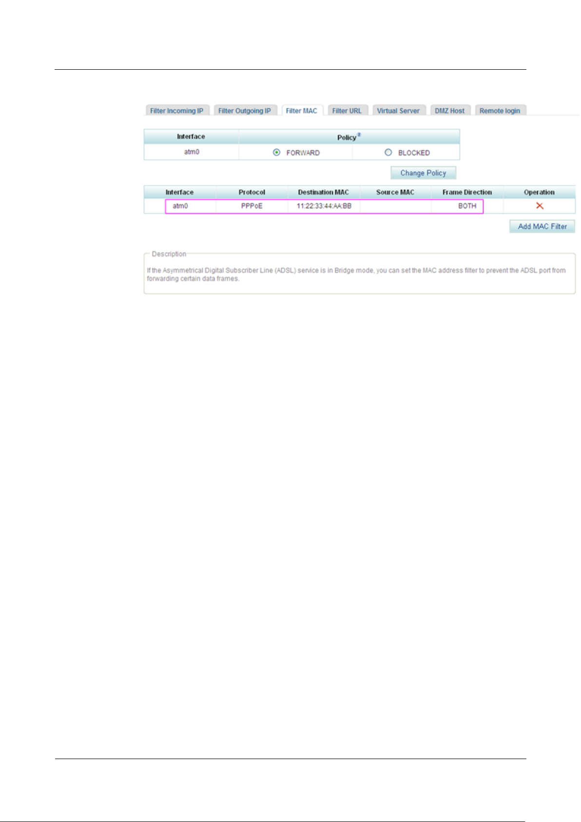
5. Click to save the settings.
Figure 7-260 shows the configuration result.
eSpace EGW1520 Enterprise Gateway
Product Documentation
7 Feature Description and Implementation
Issue 01 (2012-05-15)
Huawei Proprietary and Confidential
Copyright © Huawei Technologies Co., Ltd.
350
Figure 7-260 Configuration result
Value BOTH indicates that the ADSL port filters the MAC addresses for data frames
that are transmitted from the LAN port to the WAN port and from the WAN port to the
LAN port.
7.6.5 URL Filter
Description
----End
Using the URL filtering feature, an enterprise or a family can prevent its members from
visiting certain websites.
Principle
At present, contents at many websites are illegal or improper because they are not effectively
supervised or restricted. Therefore, more and more enterprises use the URL access control
function to ensure information security and restrict URL access.
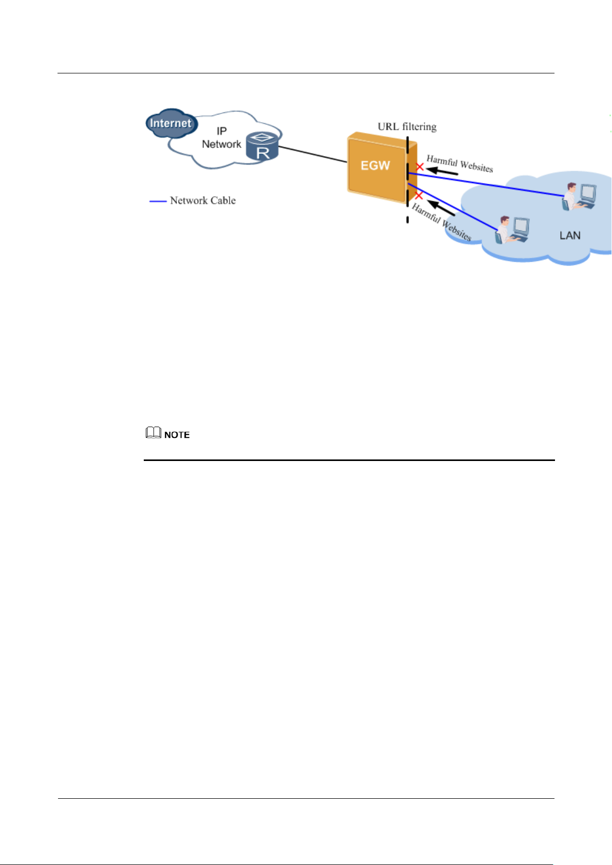
As shown in Figure 7-261, URL filtering is used to:
Control access to websites containing content including pornography, terrorism, violence,
gambling, or illegal information.
Shield phishing websites to protect employees' privacy.
Shield malicious websites to protect the enterprise's private network from attack.
Provide customized services for enterprises, for example, allow employees to access
specified websites.
eSpace EGW1520 Enterprise Gateway
Product Documentation
7 Feature Description and Implementation
Issue 01 (2012-05-15)
Huawei Proprietary and Confidential
Copyright © Huawei Technologies Co., Ltd.
351
Figure 7-261 URL filtering
Implementation
The EGW1520 provides the following URL filter modes:
Include
URLs in the whitelist can be accessed.
Exclude
URLs in the blacklist cannot be accessed.
Configuration
Use either whitelist or blacklist mode.
EGW1520 can filter the whole URL (for example, http://www.example.com) or the keyword
in the URL (for example, example.com).
Specification
Maximum number of URLs to be filtered at the same time: 100
Maximum length of each URL: 128 bytes
Full match and partial match
Limitation
Wildcards, for example, using * for full match, are not allowed in filtering rules.
Prerequisite
You have logged in to the web management system. For details, see 7.7.1 Web Management.
Procedure
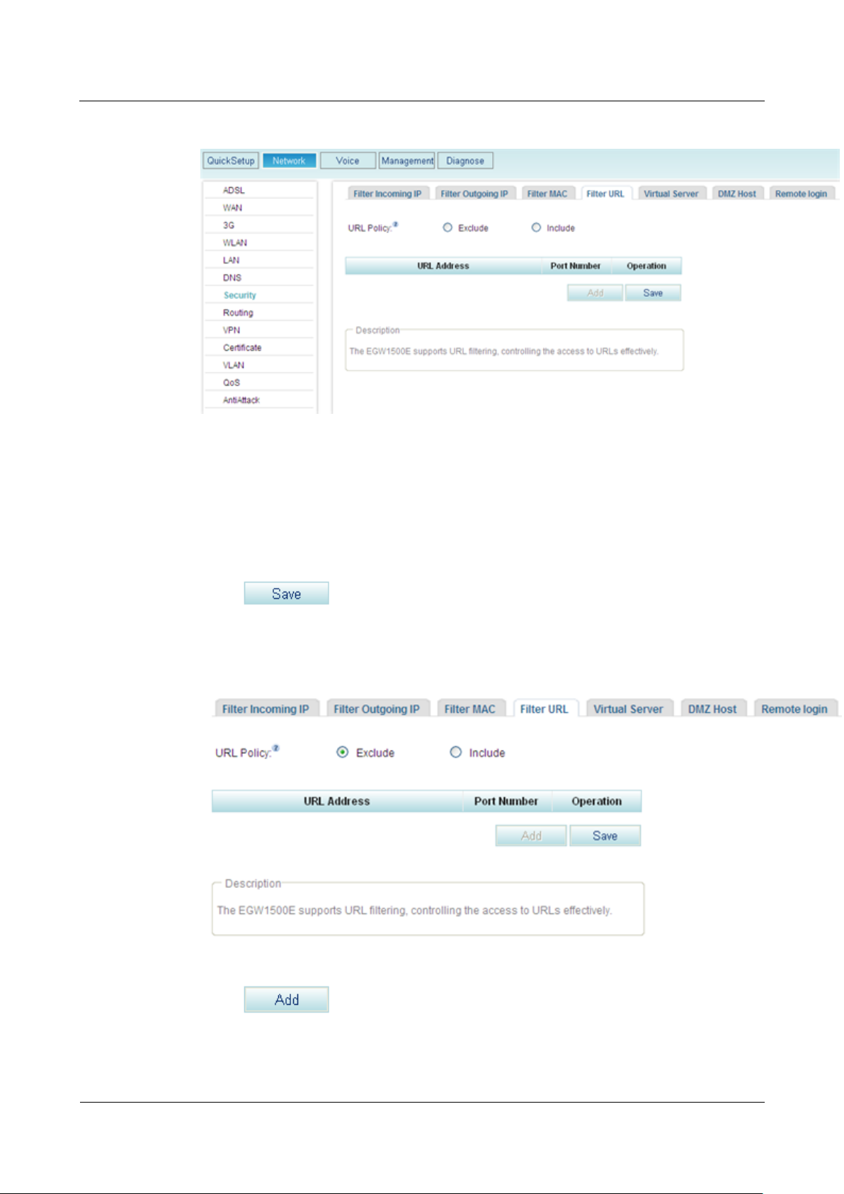
Step 1 On the web management system, choose Network > Security from the navigation tree.
Step 2 Click the Filter URL tab.
The page shown in Figure 7-262 is displayed.
eSpace EGW1520 Enterprise Gateway
Product Documentation
7 Feature Description and Implementation
Issue 01 (2012-05-15)
Huawei Proprietary and Confidential
Copyright © Huawei Technologies Co., Ltd.
352
Figure 7-262 Configuring the URL filter (1)
Step 3 Select a URL filter mode, for example, Exclude.
Include
URLs in the whitelist can be accessed.
Exclude
URLs in the blacklist cannot be accessed.
Step 4 Click to save the filter mode.
The page shown in Figure 7-263 is displayed.
Figure 7-263 Configuring the URL filter (2)
Step 5 Click to add a URL to be filtered.
The page shown in Figure 7-264 is displayed.
eSpace EGW1520 Enterprise Gateway
Product Documentation
7 Feature Description and Implementation
Issue 01 (2012-05-15)
Huawei Proprietary and Confidential
Copyright © Huawei Technologies Co., Ltd.
353
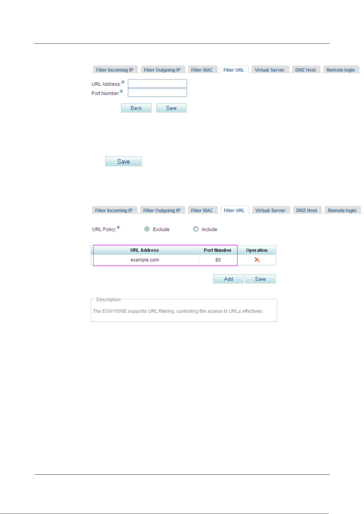
Figure 7-264 Configuring the URL filter (3)
Step 6 Enter the URL to be filtered (a compete URL or keywords) and the port number. The default
port number is 80.
Step 7 Click to save the settings.
Figure 7-265 shows the configuration result.
Figure 7-265 Configuring the URL filter (4)
----End
7.6.6 Virtual Server
After configuring the virtual server, users can access to servers in the private network, and
enable services, such as web browsing and FTP download.
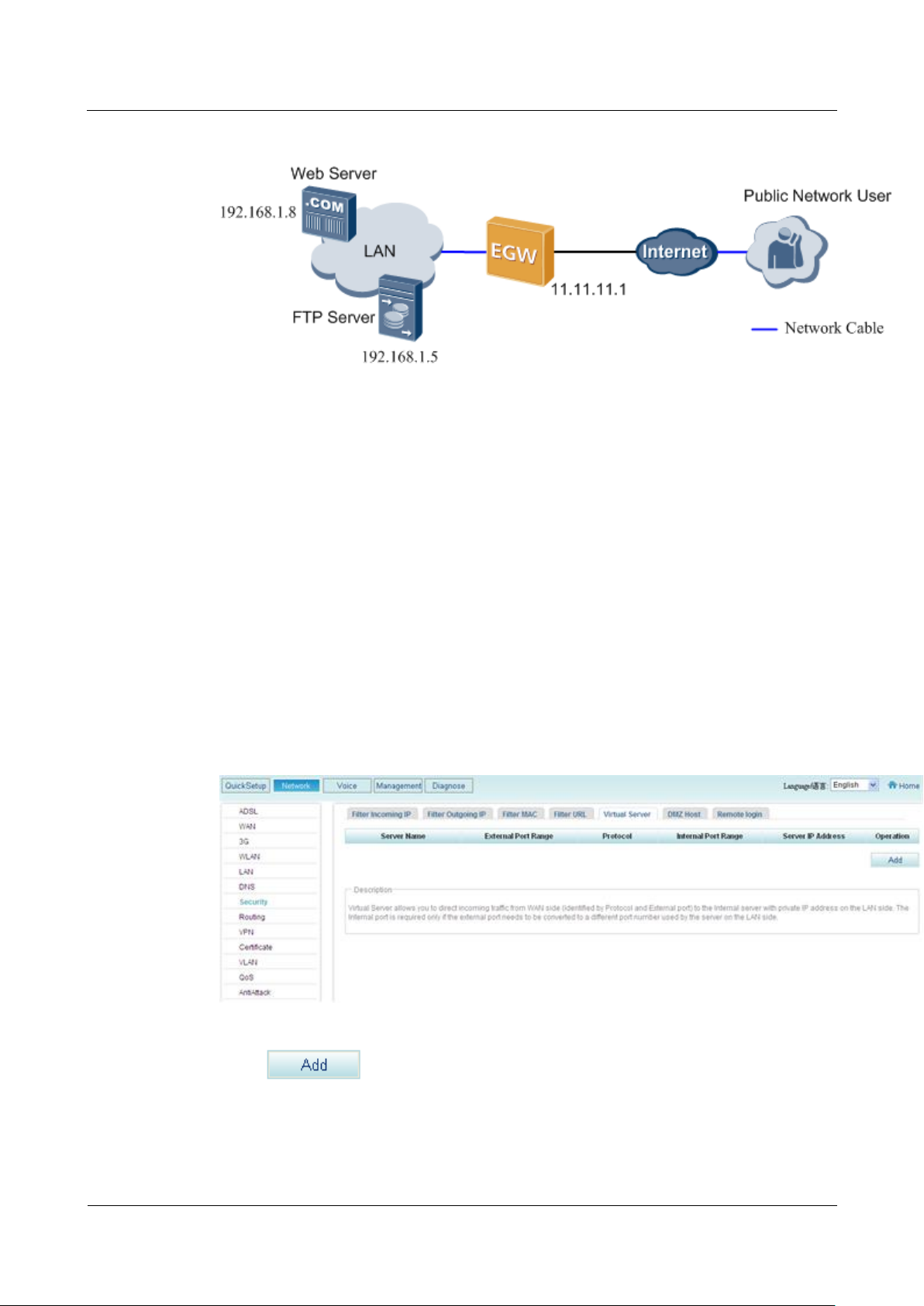
Description
A virtual server functions as a public server in the private network. Users in the external
network can use services that the virtual server provides (such as web and FTP download
services) after accessing the external address obtained from the EGW1520. Figure 7-266
shows the typical network.
eSpace EGW1520 Enterprise Gateway
Product Documentation
7 Feature Description and Implementation
Issue 01 (2012-05-15)
Huawei Proprietary and Confidential
Copyright © Huawei Technologies Co., Ltd.
354
Configuration
Figure 7-266 Typical virtual server network
Prerequisites
You have logged in to the web management system. For details, see 7.7.1 Web
Management.
The EGW1520 has been connected to the upstream network and the NAT function has
been enabled.
Required services and port numbers have been enabled on the private network.
Procedure
Step 1 On the web management system, choose Network > Security from the navigation tree.
Step 2 Click the Virtual Server tab.
The page shown in Figure 7-267 is displayed.
Figure 7-267 Configuring a virtual server (1)
Step 3 Click to add a virtual server.
The page shown in Figure 7-268 is displayed.
eSpace EGW1520 Enterprise Gateway
Product Documentation
7 Feature Description and Implementation
Issue 01 (2012-05-15)
Huawei Proprietary and Confidential
Copyright © Huawei Technologies Co., Ltd.
355
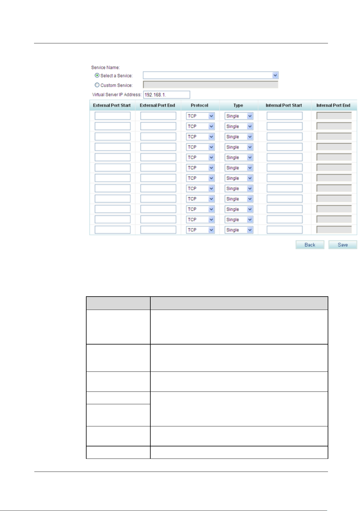
Figure 7-268 Configuring a virtual server (2)
Parameter
Description
Select a Service
Indicates the service that is provided by the virtual server, such as
the web, mail, and FTP services. The service must be enabled on
the internal server(Multiple services can be enabled on a server in
the internal network).
Custom Service
Allows you to define a service different from options in the Select
a Service drop-down list box. The service that you define must be
enabled on the internal server.
Virtual Server IP
Address
Indicates the IP address of the internal server, for example,
192.168.1.5.
External Port Start
Indicates the start and end port numbers that the virtual server
provides for external users. External users can use the port
numbers between the start and end port numbers to access the
virtual server. You are advised to use the default value.
External Port End
Protocol
Indicates the transfer protocol used by the virtual server, for
example, TCP for the web server.
Type
Indicates the port count used by the internal server.
Step 4 Set parameters according to Table 7-68.
Table 7-68 Parameter description
eSpace EGW1520 Enterprise Gateway
Product Documentation
7 Feature Description and Implementation
Issue 01 (2012-05-15)
Huawei Proprietary and Confidential
Copyright © Huawei Technologies Co., Ltd.
356
Parameter
Description
Single: The internal server uses only one port.
Range: The internal server uses multiple ports. Port numbers
on the internal server must be the same as those provided by
the virtual server for external access, and you cannot change
them.
Internal Port Start
Indicates the start and end port numbers that the internal server
provides for external users, which must be the same as the start
and end port numbers that the virtual server provides for external
users.
Internal Port End
Step 5 Click to save the settings.
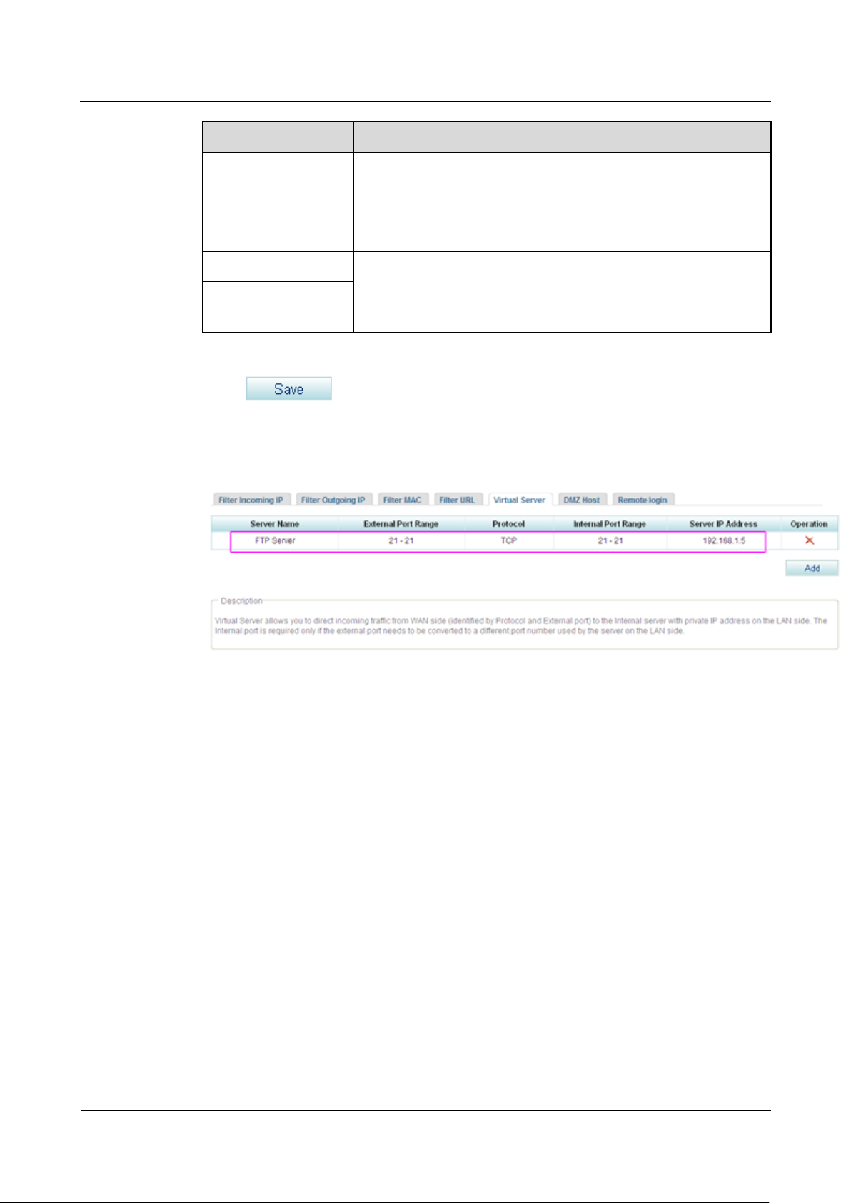
Figure 7-269 shows the configuration result.
Figure 7-269 Configuring a virtual server (3)
After the configuration is successful, external users can access the internal server through the
EGW1520 WAN port or the ADSL IP address and port number.
----End
Typical Configuration Example
Network Requirements
Users access the Internet through EGW1520 and want to configure a web server and an FTP
server on the private network to provide web and FTP download services for external users.
The network requirements are as follows:
Connect EGW1520 to the Internet through the WAN port whose IP address is 11.11.11.1.
Configure a web server and an FTP server on the private network, whose IP addresses
are 192.168.1.8 and 192.168.1.5 respectively.
After the configuration is complete, external systems can access the internal web server
and FTP server.
Typical Network
eSpace EGW1520 Enterprise Gateway
Product Documentation
7 Feature Description and Implementation
Issue 01 (2012-05-15)
Huawei Proprietary and Confidential
Copyright © Huawei Technologies Co., Ltd.
357
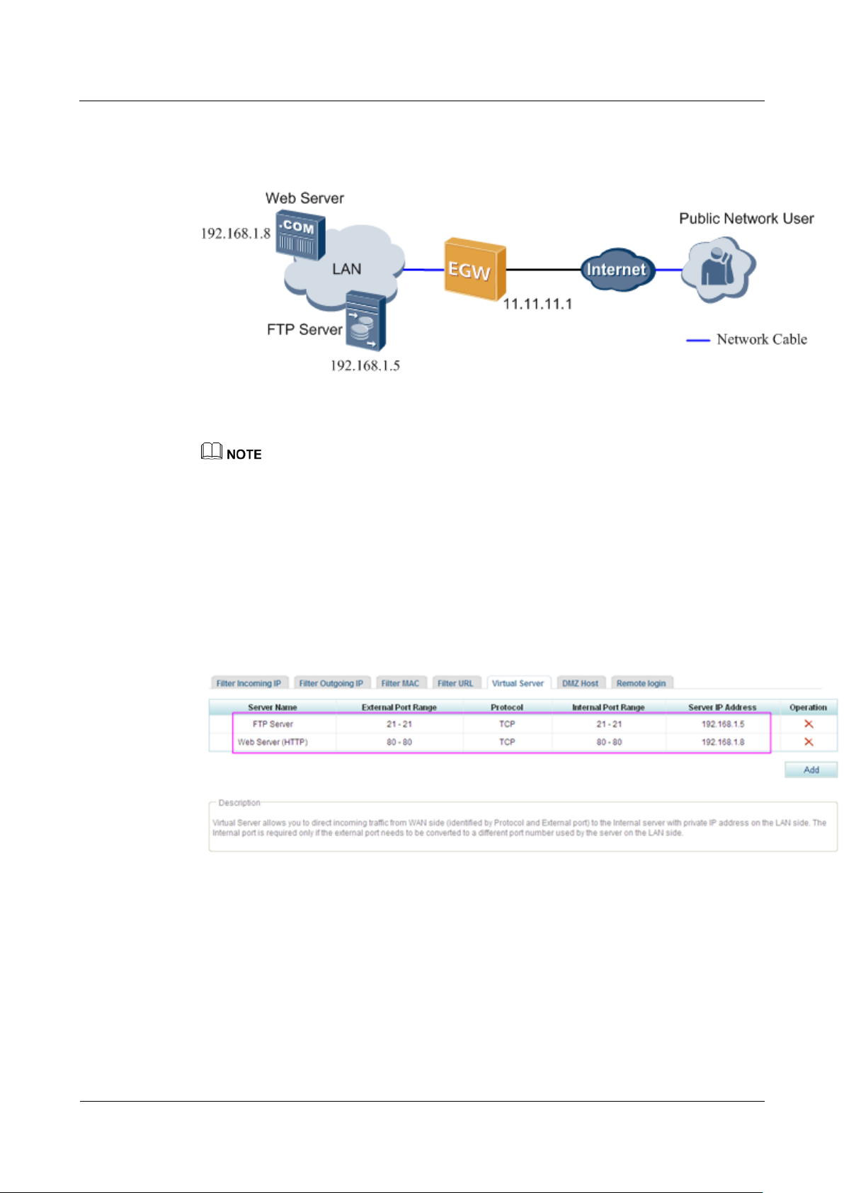
Figure 7-270 shows the typical network diagram of the virtual server.
Figure 7-270 Typical network
Procedure
For details on how to configure the web and FTP servers, see the relevant documents.
For details on how to add a virtual server, see Adding a virtual server.
1. Configure the web server software on the server whose IP address is 192.168.1.8 and
enable the port number 80. Configure the FTP server software on the server whose IP
address is 192.168.1.5 and enable the port number 21.
For details, see the related user guide.
2. On the web management system, add a virtual server.
Figure 7-271 shows the configuration result.
Figure 7-271 Configuration result
Verification
If an external user enters http://11.11.11.1 in the address box of the Internet Explorer and
accesses the web server successfully, the web server is configured successfully.
Otherwise, verify the configurations of the web server software and the EGW1520
virtual server.
If an external user enters ftp://11.11.11.1 in the address box of the Internet Explorer and
accesses the FTP server successfully, the FTP server is configured successfully.
Otherwise, verify the configurations of the FTP server software and the EGW1520
virtual server.
eSpace EGW1520 Enterprise Gateway
Product Documentation
7 Feature Description and Implementation
Issue 01 (2012-05-15)
Huawei Proprietary and Confidential
Copyright © Huawei Technologies Co., Ltd.
358
7.6.7 DMZ
Description
An external user must use the IP address that EGW1520 provides for external users (WAN
port IP address 11.11.11.1 in this example) to access the internal server.
A virtual server enables external users to access internal servers on the private network. When
multiple services are running on internal servers, several virtual servers must be configured.
This makes the configuration complicated. To simplify the configuration, configure only the
IP addresses for internal servers in the Demilitarized Zone (DMZ). External users can access
only the internal servers (such as the WWW and FTP servers) in the DMZ but cannot use the
other internal resources. This protects the internal network against illegal access.
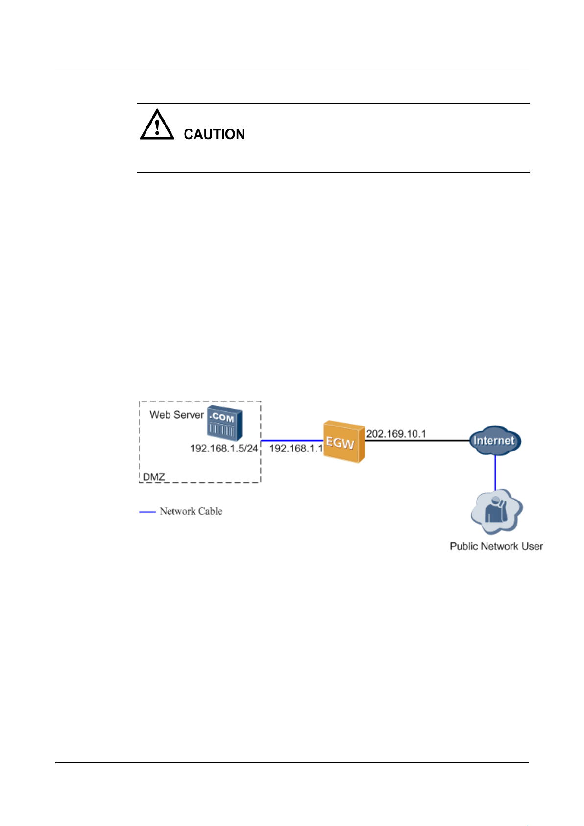
The DMZ is deployed between a public network and an enterprise's private network. Some
public servers (such as the web server and FTP server) are deployed in the DMZ, as shown in
Figure 7-272. The EGW1520 forwards all access requests from the public network (excluding
those meeting NAT requirements) to the DMZ. This protects the internal network.
Figure 7-272 DMZ implementation
The following uses a web server in the DMZ as an example to describe the DMZ
implementation.
1. After receiving external HTTP packets, the EGW1520 checks the packets. If the packets
do not meet NAT requirement, EGW1520 forwards the packets to the DMZ.
2. EGW1520 converts the destination address of request packets to the DMZ web server's
preset IP address, and sends the packets to the DMZ web server.
3. After receiving the request packets, the web server sends response packets to the
computer on the public network. Then NAT is performed.
Configuration
Prerequisites
eSpace EGW1520 Enterprise Gateway
Product Documentation
7 Feature Description and Implementation
Issue 01 (2012-05-15)
Huawei Proprietary and Confidential
Copyright © Huawei Technologies Co., Ltd.
359
You have logged in to the web management system. For details, see 7.7.1 Web
Management.
You have connected to the upstream network and the NAT function has been enabled.
For details on how to connect to the upstream network, see 7.2 Connection Modes.
Procedure
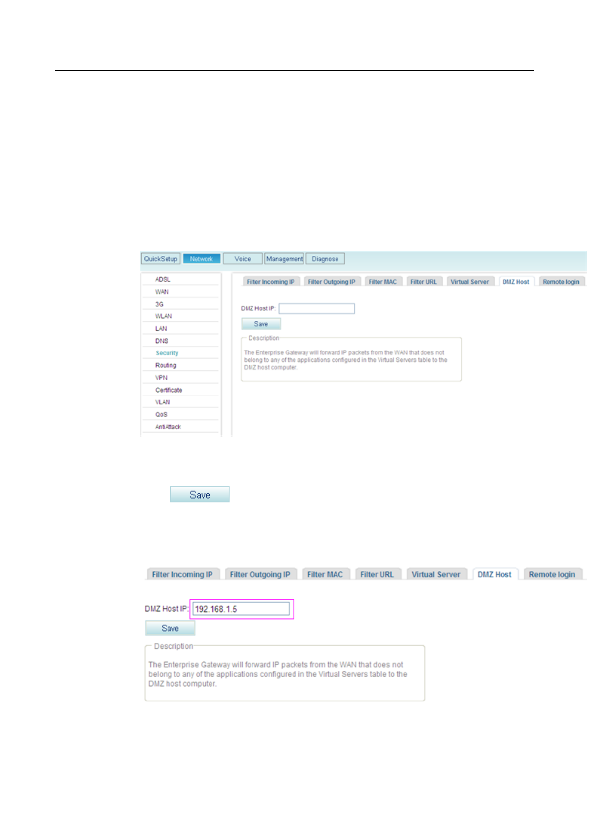
Step 1 On the web management system, choose Network > Security from the navigation tree.
Step 2 Click the DMZ Host tab.
The page shown in Figure 7-273 is displayed.
Figure 7-273 Configuring the DMZ (1)
Step 3 Enter the DMZ host IP address, for example, 192.168.1.5.
Step 4 Click to save the settings.
Figure 7-274 shows the configuration result.
Figure 7-274 Configuring the DMZ (2)
----End
eSpace EGW1520 Enterprise Gateway
Product Documentation
7 Feature Description and Implementation
Issue 01 (2012-05-15)
Huawei Proprietary and Confidential
Copyright © Huawei Technologies Co., Ltd.
360
Typical Example
Networking Requirements
Assume that a user who uses the EGW1520 to connect to the Internet wants to deploy a web
server and an FTP server on the intranet to provide website services and FTP resource
download services for users on the external network. The network requirements are as
follows:
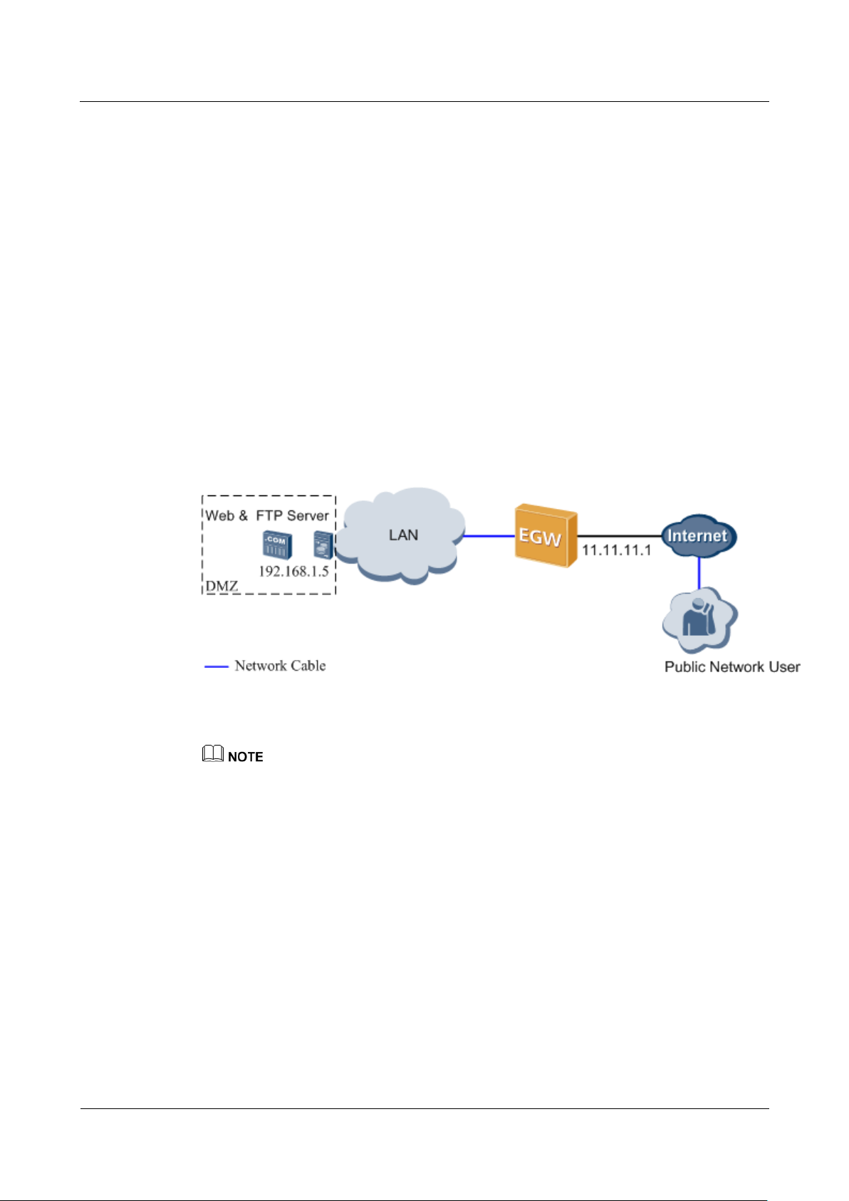
Typical Network
Figure 7-275 shows the typical network.
Figure 7-275 DMZ typical network
The EGW1520 uses a WAN port to connect to the Internet. The IP address of the WAN
port is 11.11.11.1.
Deploy a web server and an FTP server on the same computer on the EGW1520's
intranet. The IP address is 192.168.1.5.
Configure the DMZ to enable users on the external network to access the web server and
FTP server.
Configuration Procedure
For details on how to configure the web and FTP servers, see the relevant documents.
For details on how to configure the DMZ, see Configuration.
1. On the computer whose IP address is 192.168.1.5, configure the web server and the FTP
server.
For details, see the related user guide.
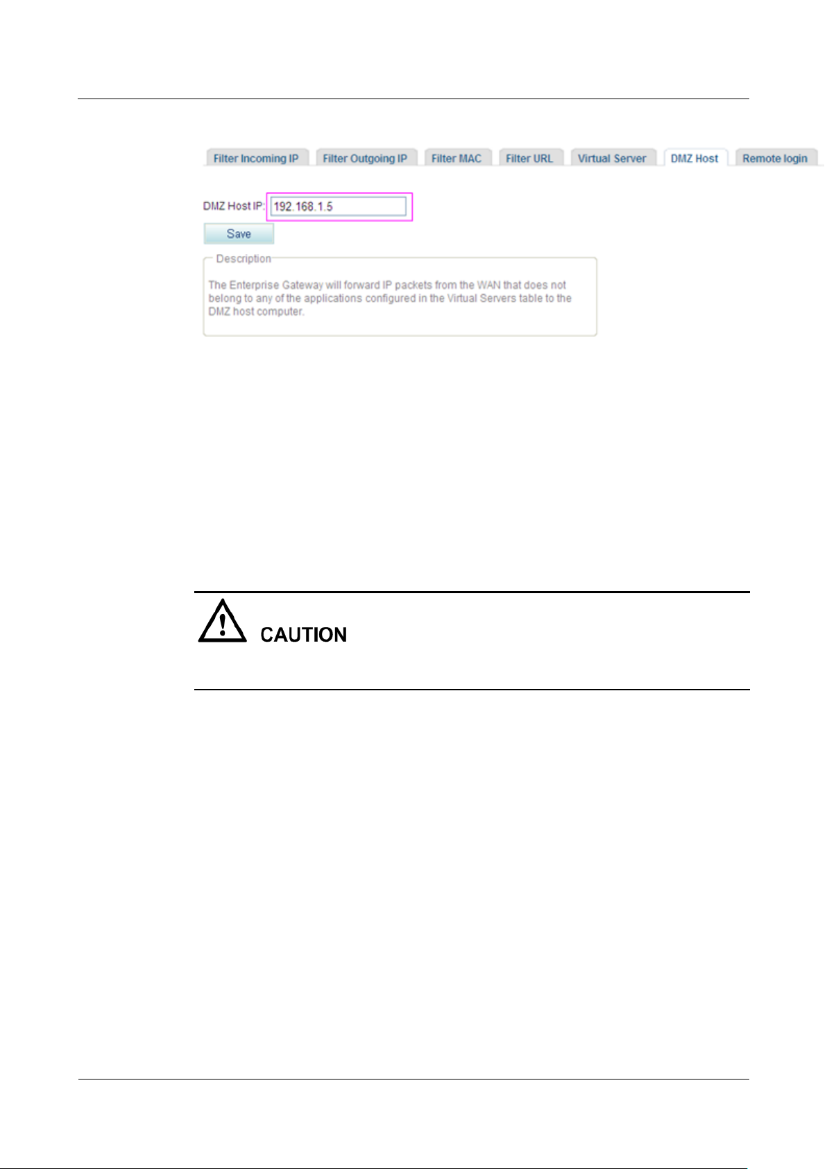
2. Configure the DMZ on the web management system.
Figure 7-276 shows the configuration result.
eSpace EGW1520 Enterprise Gateway
Product Documentation
7 Feature Description and Implementation
Issue 01 (2012-05-15)
Huawei Proprietary and Confidential
Copyright © Huawei Technologies Co., Ltd.
361
Figure 7-276 Configuration result
Verification
Start the Internet Explorer and enter http://11.11.11.1 in the address box as a user on the
external network. If the web server is connected, the configuration is successful. If the
web server is not connected, check the IP address setting of the DMZ host on the web
server and EGW1520.
Start the Internet Explorer and enter ftp://11.11.11.1 in the address box as a user on the
external network. If the FTP server is connected, the configuration is successful. If the
FTP server is not connected, check the IP address setting of the DMZ host on the FTP
server and EGW1520.
An external user must use EGW1520 external IP address (in this topic, it is the IP address of
the WAN port 11.11.11.1) to access internal servers.
7.6.8 Remote Login
This topic describes how to remotely configure and maintain the EGW1520 by connecting to
uplink ports (WAN, ADSL, or 3G port).
The EGW1520 provides a public IP address for remote maintenance.
Enabling Remote Login
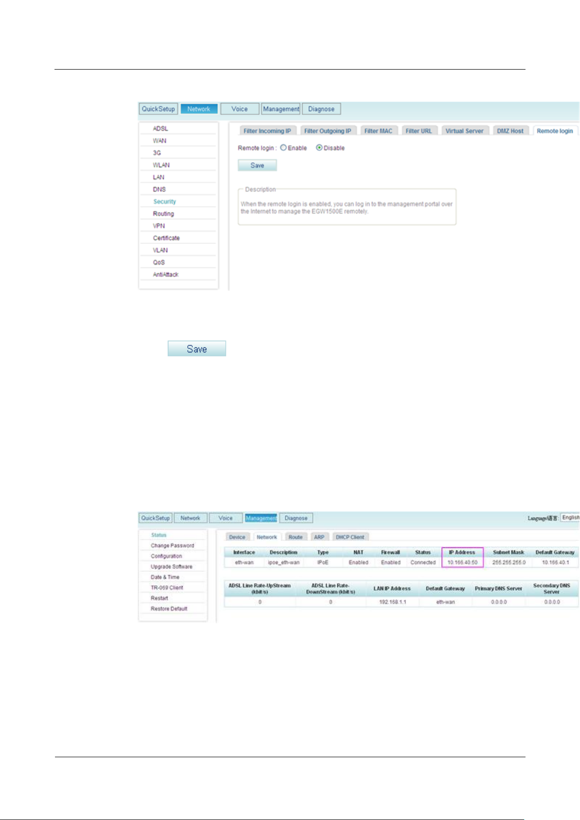
Step 1 On the web management system, choose Network > Security from the navigation tree.
Step 2 Click the Remote login tab.
The page shown in Figure 7-277 is displayed.
eSpace EGW1520 Enterprise Gateway
Product Documentation
7 Feature Description and Implementation
Issue 01 (2012-05-15)
Huawei Proprietary and Confidential
Copyright © Huawei Technologies Co., Ltd.
362
Figure 7-277 Configuring remote login
Step 3 Select Enable.
Step 4 Click to save the settings.
----End
Obtaining the Public IP Address of EGW1520
Step 1 On the web management system, choose Management > Status from the navigation tree.
Step 2 Click the Network tab.
The page shown in Figure 7-278 is displayed.
Figure 7-278 Obtaining the IP address of EGW1520
Step 3 View the IP address of EGW1520. The IP address in Figure 7-278 is the public IP address of
EGW1520.
----End
eSpace EGW1520 Enterprise Gateway
Product Documentation
7 Feature Description and Implementation
Issue 01 (2012-05-15)
Huawei Proprietary and Confidential
Copyright © Huawei Technologies Co., Ltd.
363
Logging In to EGW1520 Remotely
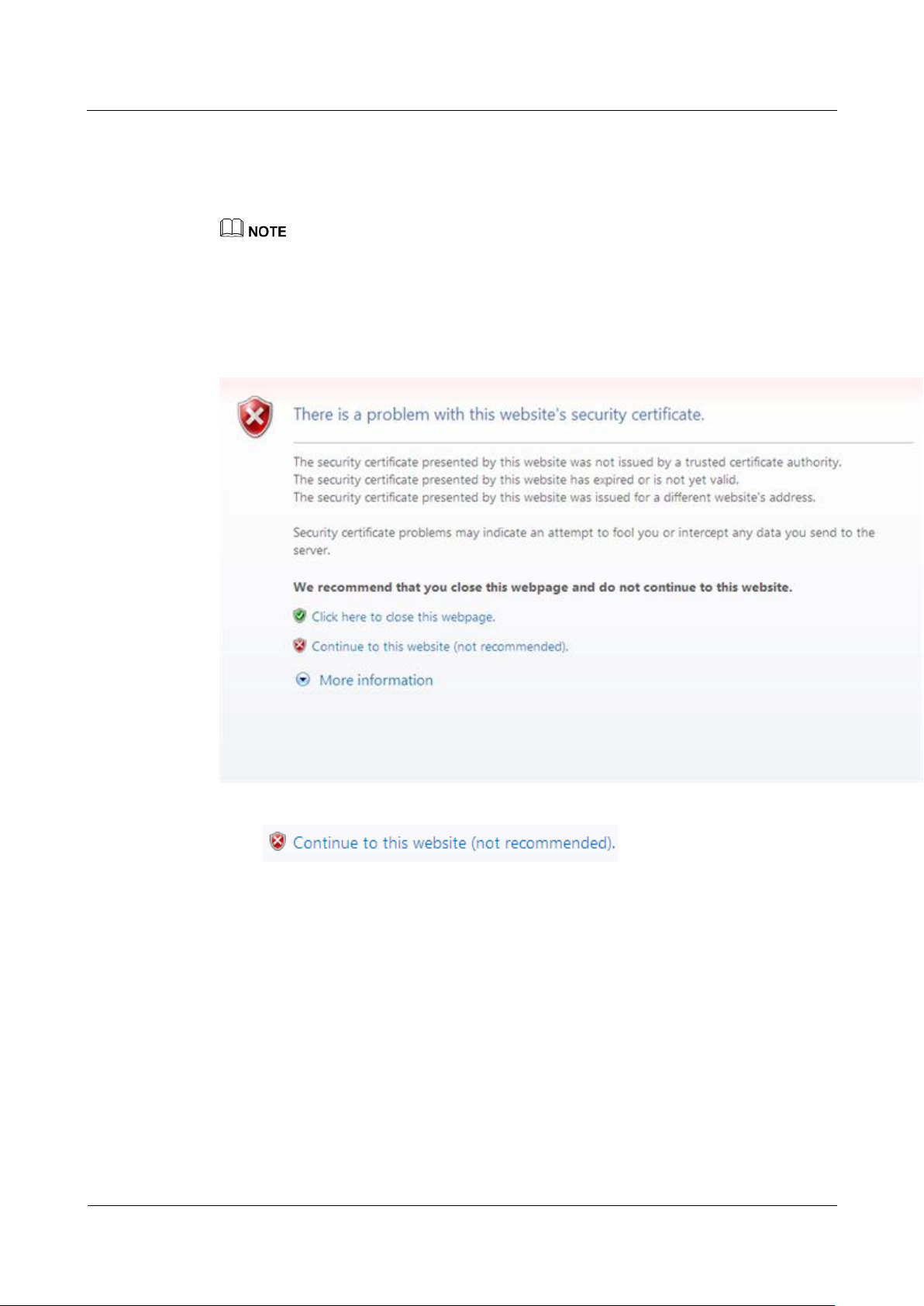
Step 1 Use the Internet Explorer (6.0 or a later version) on your computer to access the public IP
address of EGW1520.
When you log in to the EGW1520 using HTTP, the EGW1520 automatically changes your login mode
to HTTPS to ensure communication security.
If the security level of your browser is not set properly, the system notifies you that the
certificate is incorrect, as shown in Figure 7-279.
Figure 7-279 Prompt information
Click to continue your operation.
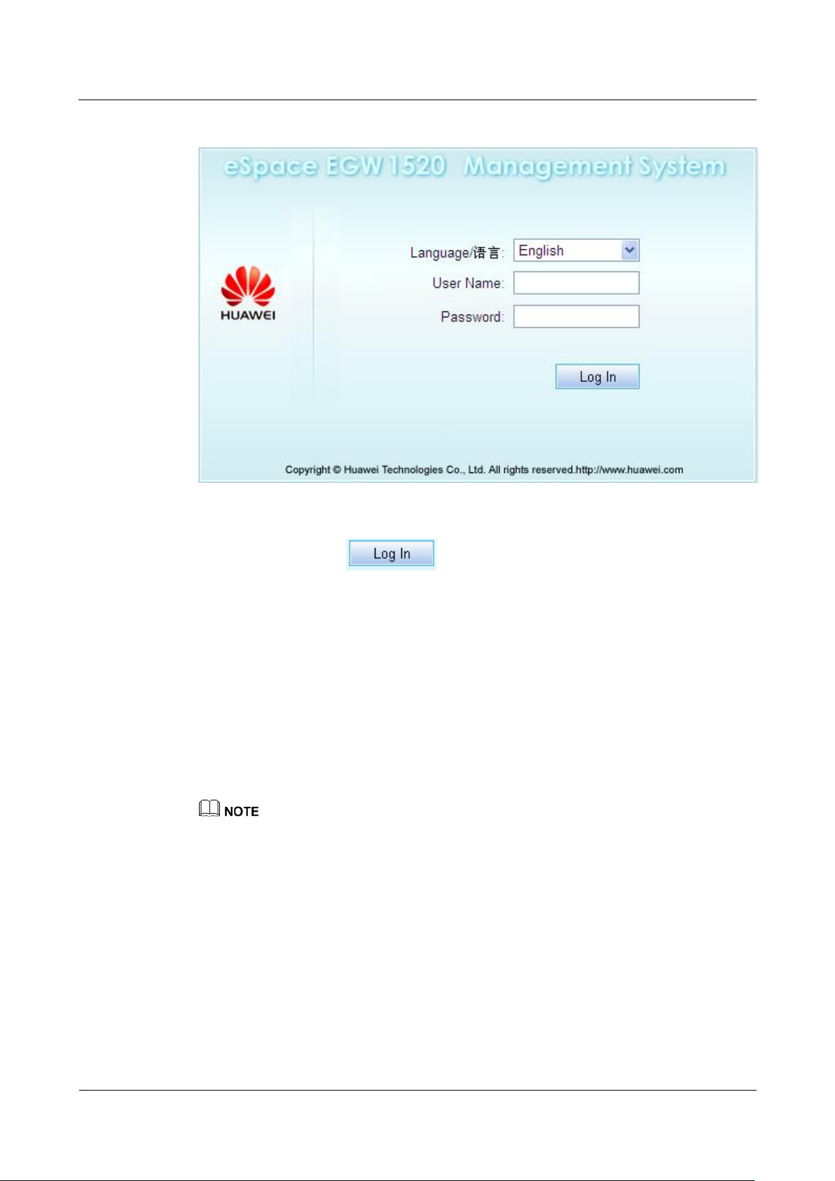
The page shown in Figure 7-280 is displayed.
eSpace EGW1520 Enterprise Gateway
Product Documentation
7 Feature Description and Implementation
Issue 01 (2012-05-15)
Huawei Proprietary and Confidential
Copyright © Huawei Technologies Co., Ltd.
364
Figure 7-280 Logging in to the EGW1520
Step 2 Enter the user name (initial user name is admin) and password (initial password is
Admin@123) and click .
----End
7.7 Operations and Maintenance
The EGW1520 can be managed on web pages or in TR-069 mode.
7.7.1 Web Management
The web management system allows users to set parameters, detect faults, and upgrade
devices.
The EGW1520 also supports remote login, from which you can remotely configure and maintain the
EGW1520. For details about how to remotely log in to the EGW1520, see 7.6.8 Remote Login.
Prerequisite
Before logging in to the web management system, ensure that the configuration environment
is ready.
1. Prepare a PC (maintenance terminal).
The PC must meet the following requirements:
− Has the Ethernet adapter installed, supporting TCP/IP.
− Has Windows XP or later operating system installed.

eSpace EGW1520 Enterprise Gateway
Product Documentation
7 Feature Description and Implementation
Issue 01 (2012-05-15)
Huawei Proprietary and Confidential
Copyright © Huawei Technologies Co., Ltd.
365
− Has Microsoft Internet Explorer 6.0 or later version without configuring the proxy
server.
− Supports the resolution 1024 x 768 or above.
2. The console cables have been connected.
You can connect cables by using either of the following methods according to the
network:
− Use the straight-through cable to connect the EGW1520 LAN port to the PC network
port.
− Use the straight-through cable to connect the EGW1520 LAN port to the PC network
port through the switch or hub.
3. The PC IP address has been set.
The IP addresses of the PC and EGW1520 must be on the same network segment. For
example, if IP address of the EGW1520 is 192.168.1.1 (default value), the PC IP address
can be set to 192.168.1.x, where x ranges from 2 to 254.
By default, DHCP is enabled on an EGW1520. The PC can use the automatic mode to obtain
the IP address.
Background
Procedure
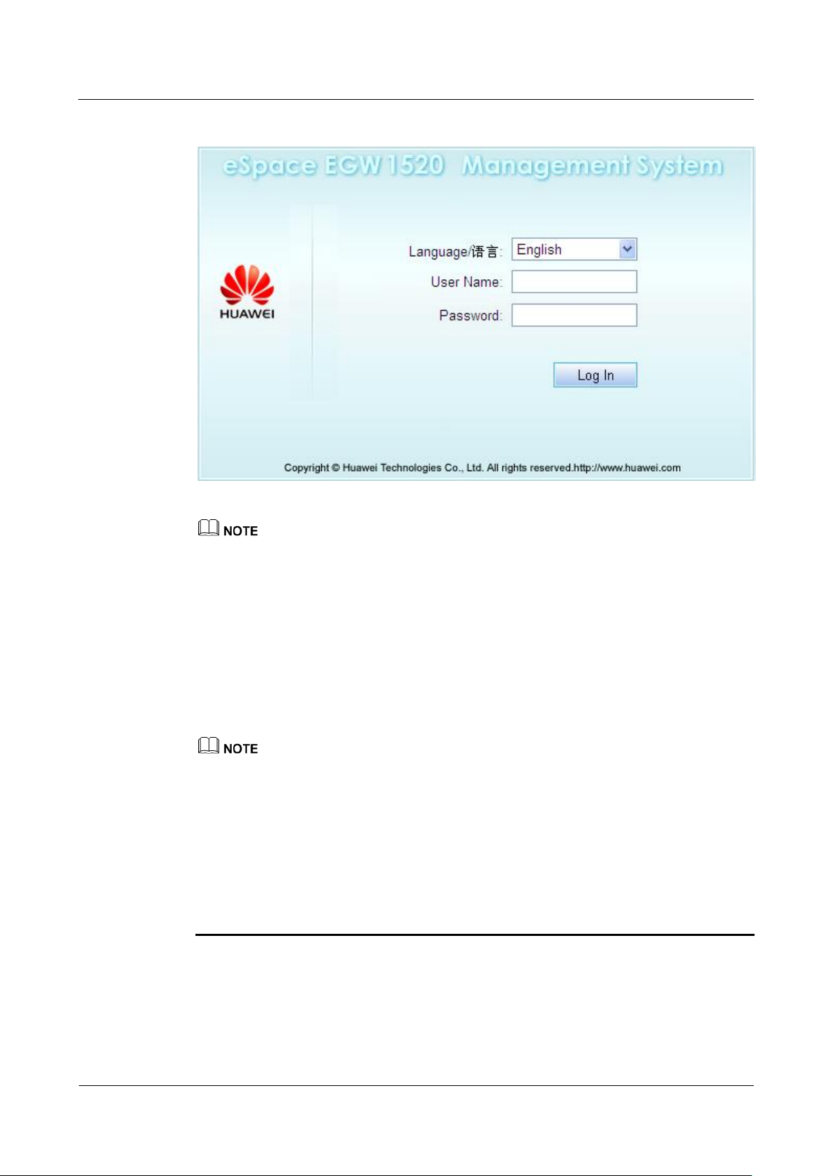
Step 1 Log in to the EGW1520 using Internet Explorer 6.0 or later. The default URL is
Users can access the web management system in the following two modes:
HTTPS
The web browser interacts with the EGW1520 using HTTPS, which ensures user
information security.
HTTP
The web browser interacts with the EGW1520 using HTTP.
Only HTTPS access mode is enabled on EGW1520 by default. The HTTP access mode can be
enabled on the page for configuring the LAN. For details, see Configuring the LAN.
HTTP transmits plain text. Use HTTP to perform web management only in trusted networks.
If only the HTTPS mode is enabled, the system switches to the HTTPS mode automatically when
you access the EGW1520 in HTTP mode.
https://192.168.1.1.
The page shown in Figure 7-281 is displayed.
eSpace EGW1520 Enterprise Gateway
Product Documentation
7 Feature Description and Implementation
Issue 01 (2012-05-15)
Huawei Proprietary and Confidential
Copyright © Huawei Technologies Co., Ltd.
366
Figure 7-281 Logging in to the web management system (1)
The default IP address of the EGW1520, login user name, and password can be obtained from the
label at the bottom of the EGW1520.
After logging in to the web management system, you can change IP address of the EGW1520. For
details, see Configuring the LAN.
Step 2 Enter the user name and password, and click Log In.
Administrator: The user name is admin and the password is Admin@123.
Common user: Both the initial user name and password are the internal number of a
common user.
Choose Management > Password to change the password after the initial login.
Make a note of your password and keep it in a safe place. Do not share your password
with anyone. If you forget your password, press and hold the RESET button on EGW1520
for more than six seconds, and log in to the web management system using the default
password Admin@123. The configuration is restored to factory settings.
If you fail to log in to the web management system for 5 consecutive times in 10 minutes,
the system locks your PC IP address for 30 minutes.
If you do not perform any operation in 10 minutes after logging in to the web management
system, the login times out and the system requires re-login to ensure security.
----End

eSpace EGW1520 Enterprise Gateway
Product Documentation
7 Feature Description and Implementation
Issue 01 (2012-05-15)
Huawei Proprietary and Confidential
Copyright © Huawei Technologies Co., Ltd.
367
7.7.2 TR-069
Description
Principle
The Technical Report 069 (TR-069) is a DSL forum (which was later renamed as broadband
forum) technical specification entitled CPE WAN Management Protocol (CWMP). It defines
an application layer protocol for remote management of end-user devices.
This topic describes the principle, implementation, specification, and limitation of the
TR-069.
The Technical Report 069 (TR-069) is a DSL forum (which was later renamed as broadband
forum) technical specification entitled CPE WAN Management Protocol (CWMP). It defines
an application layer protocol for remote management of end-user devices. As a bidirectional
SOAP/HTTP-based protocol, it provides the communication between customer premises
equipment (CPE) and Auto Configuration Servers (ACS). It includes both a safe auto
configuration and the control of other CPE management functions within an integrated
framework.
Customer premises equipment, such as gateways and set top boxes (STBs) are scattered on
the user side. Maintenance personnel need to provide on-site services when configuration
modification or troubleshooting is required, which increases management difficulty. TR-069
enables you to manage and maintain user's devices remotely on the network side. Details
about the functions that TR-069 provides are as follows:
Implementation
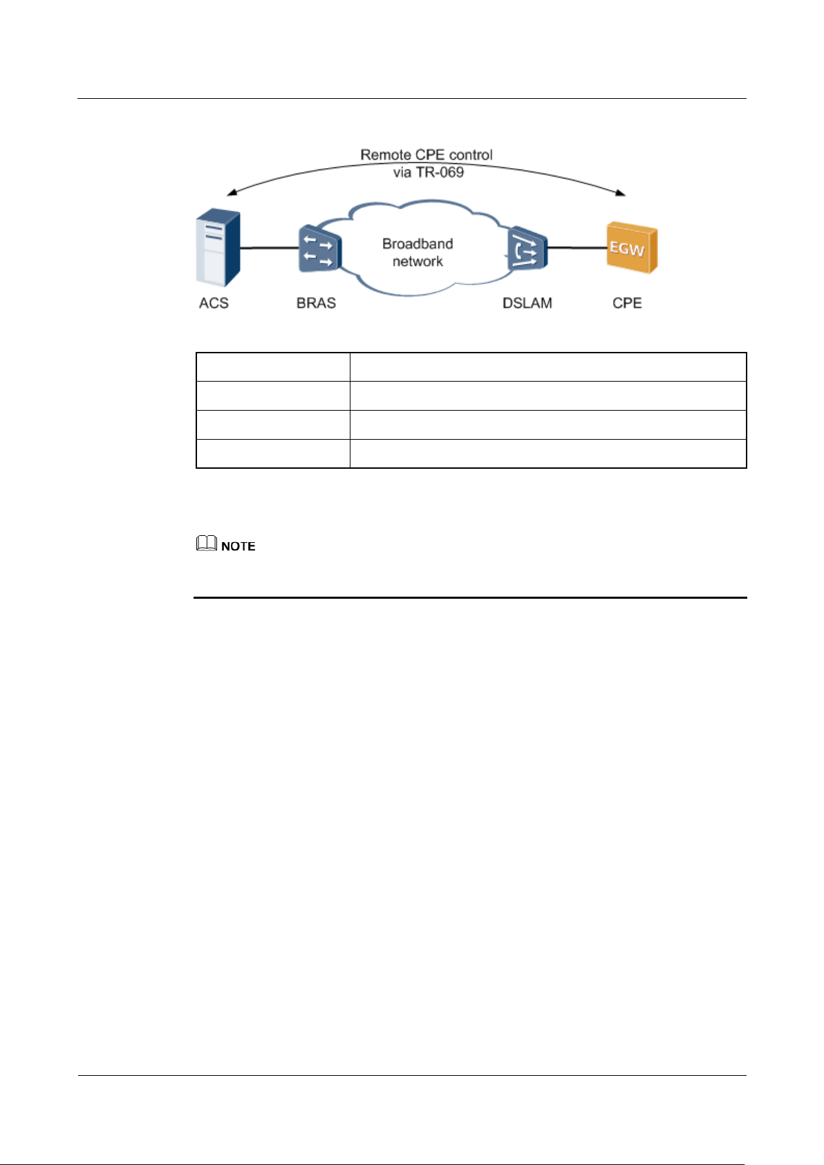
As a CPE, EGW1520 supports TR-069, Figure 7-282 shows TR-069 network.
Configuration management
Installs CPE without configurations and modifies parameter settings remotely.
Version management
Manages CPE software and firmware, for example, download the software version, and
back up and restore the configuration file.
Remote monitoring
Monitors the CPE status and performance, and queries the CPE status.
GUI-based management
Manages NEs on the EMS in GUI mode.
Alarm management
Reports alarms to the EMS and instructs the EMS to delete an alarm in time once the
alarm is cleared.
eSpace EGW1520 Enterprise Gateway
Product Documentation
7 Feature Description and Implementation
Issue 01 (2012-05-15)
Huawei Proprietary and Confidential
Copyright © Huawei Technologies Co., Ltd.
368
Figure 7-282 TR-069 network diagram
ACS
Auto-Configuration Server
BRAS
Broadband Remote Access Server
DSLAM
Digital Subscriber Line Access Multiplexer
CPE
Customer Premises Equipment
EGW1520 uses the ADSL port or WAN port to connect to ACS. The preceding figure uses the
ADSL port as an example.
Specification
TR-069
TR-098
TR-104
Limitation
N/A
Setting TR-069 Parameters on the ACS
This topic describes how to set TR-069 parameters on the ACS.
TR-069 Connection Parameters
For details about configurations on the ACS, see the related ACS configuration guide. This
topic only lists TR-069 parameters for the ACS to connect to EGW1520, as shown in Table
7-69.
eSpace EGW1520 Enterprise Gateway
Product Documentation
7 Feature Description and Implementation
Issue 01 (2012-05-15)
Huawei Proprietary and Confidential
Copyright © Huawei Technologies Co., Ltd.
369
Table 7-69 TR-069 connection parameters
Parameter
Description
ACS URL
Indicates the ACS URL. For example, http://www.acs.com.
ACS User Name
Indicates the user name for the ACS to authenticate the
TR-069 client, which must be the same as the user name on
the ACS.
ACS Password
Indicates the password for the ACS to authenticate the
TR-069 client, which must be the same as the user name on
the ACS.
Connection Request User
Name
Indicates the user name for the TR-069 client to authenticate
the ACS, which must be the same as the user name on the
TR-069 client.
Connection Request
Password
Indicates the password for the TR-069 client to authenticate
the ACS, which must be the same as the user name on the
TR-069 client.
Connection Request URL
Indicates the URL of the TR-069 client. For example,
http://192.168.1.1:8081/CPE. 192.168.1.1 is the IP address of
the EGW1520 local area network (LAN) gateway.
Setting TR-069 Parameters on the CPE
This topic describes how to set TR-069 parameters on the EGW1520.
Prerequisites
You have logged in to the web management system. For details, see 7.7.1 Web Management.
Procedure
Step 1 On the web management system, choose Management > TR-069 Client from the navigation
tree.
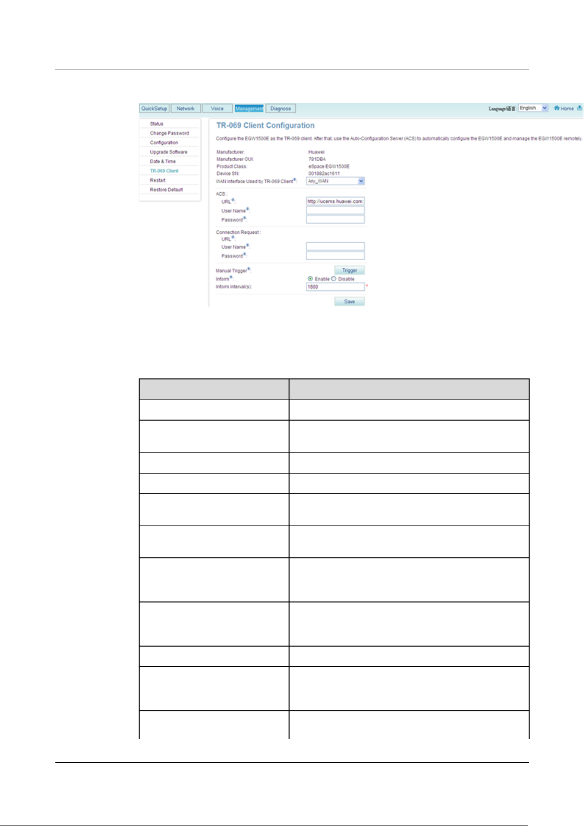
The page shown in Figure 7-283 is displayed.
eSpace EGW1520 Enterprise Gateway
Product Documentation
7 Feature Description and Implementation
Issue 01 (2012-05-15)
Huawei Proprietary and Confidential
Copyright © Huawei Technologies Co., Ltd.
370
Figure 7-283 TR-069 client configuration
Parameter
Description
Manufacturer
Indicates the device manufacturer.
Manufacturer OUI
Indicates the organizationally Unique Identifier (OUI)
of the manufacturer.
Product Class
Indicates the device model.
Device SN
Indicates the device sequence number.
WAN Interface Used by TR-069
Client
Indicates the WAN port on the TR-069 client
connected to the ACS.
ACS URL
Indicates the ACS URL. For example,
http://www.acs.com.
ACS User Name
Indicates the user name for the ACS to authenticate the
TR-069 client, which must be the same as the user
name on the ACS.
ACS Password
Indicates the password for the ACS to authenticate the
TR-069 client, which must be the same as the user
name on the ACS.
Connection Request URL
Indicates the URL of the TR-069 client.
Connection Request User Name
Indicates the user name for the TR-069 client to
authenticate the ACS, which must be the same as the
user name on the TR-069 client.
Connection Request Password
Indicates the password for the TR-069 client to
authenticate the ACS, which must be the same as the
Step 2 Set parameters according to Table 7-70.
Table 7-70 Parameter description
eSpace EGW1520 Enterprise Gateway
Product Documentation
7 Feature Description and Implementation
Issue 01 (2012-05-15)
Huawei Proprietary and Confidential
Copyright © Huawei Technologies Co., Ltd.
371
Parameter
Description
user name on the TR-069 client.
Manual Trigger
Initiates the session to the ACS manually by clicking
Trigger.
Inform
Indicates whether to initiate a session to the ACS
periodically.
Inform Interval(Sec)
Indicates the interval to initiate a session to the ACS, in
seconds. The default value is 1800.
Result
Step 3 Click to save the settings.
----End
After the EGW1520 is connected to the ACS by using TR-069, use ACS to configure and
manage the EGW1520. TR-069 parameters reference lists parameters in the TR-069 data
model.

eSpace EGW1520 Enterprise Gateway
Product Documentation
8 Diagnosis Mode
Issue 01 (2012-05-15)
Huawei Proprietary and Confidential
Copyright © Huawei Technologies Co., Ltd.
372
About This Chapter
This topic describes diagnosis modes for the EGW1520.
8.1 Enabling the Debug Log
This topic describes how to enable the debug log for each process. The system can generate
the debug logs for different processes.
8 Diagnosis Mode
8.2 Configuring Traffic Mirroring
This section describes how to configure traffic mirroring to capture packets. Traffic mirroring
allows you to use a packet capture tool on the mirroring port to obtain information about
packets entering or leaving the monitored port.
8.3 Downloading Black Box Files
This topic describes how to download black box files.
8.4 Pinging IP Addresses
This topic describes how to ping an IP address. Using the ping function, you can ping the peer
device of the EGW1520 to check the connection between them.
8.1 Enabling the Debug Log
This topic describes how to enable the debug log for each process. The system can generate
the debug logs for different processes.
Large amounts of logs are generated during the EGW1520 running process.
By default, the system does not generate the debug logs. To generate the debug logs, enable
the debug log and log generation function, set the log level to debug, and configure the log
saving mode. For details, see 9.4 Managing System Logs.
Procedure
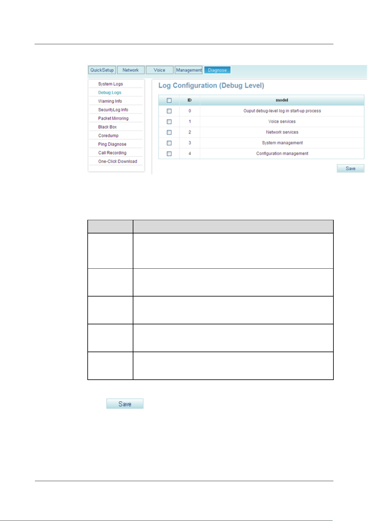
Step 1 On the web management system, choose Diagnose > Debug Logs from the navigation tree.
The page shown in Figure 8-1 is displayed.
eSpace EGW1520 Enterprise Gateway
Product Documentation
8 Diagnosis Mode
Issue 01 (2012-05-15)
Huawei Proprietary and Confidential
Copyright © Huawei Technologies Co., Ltd.
373
Figure 8-1 Enabling the debug logs for each module
Parameter
Description
Output
debug-level
log in start-up
process
Debug logs are generated when the system starts. For example, when you
want to debug the system during system startup, enable this function.
Voice services
Debug logs for voice services are generated. For example, when the
synchronization server cannot synchronize service data, enable this
function.
Network
services
Debug logs for network services are generated. For example, when you
want to view the IP address obtained by EGW1520 that functions as a
client, enable this function.
System
management
Debug logs for system management are generated. For example, when
you want to view message sending and receiving information in the
system, enable this function.
Configuration
management
Debug logs for configuration management are generated. For example,
when you want to monitor network time synchronization, enable this
function.
Step 2 Enable the debug logs for modules according to Table 8-1.
Table 8-1 Parameter description
Step 3 Click to save the settings.
----End
eSpace EGW1520 Enterprise Gateway
Product Documentation
8 Diagnosis Mode
Issue 01 (2012-05-15)
Huawei Proprietary and Confidential
Copyright © Huawei Technologies Co., Ltd.
374
8.2 Configuring Traffic Mirroring
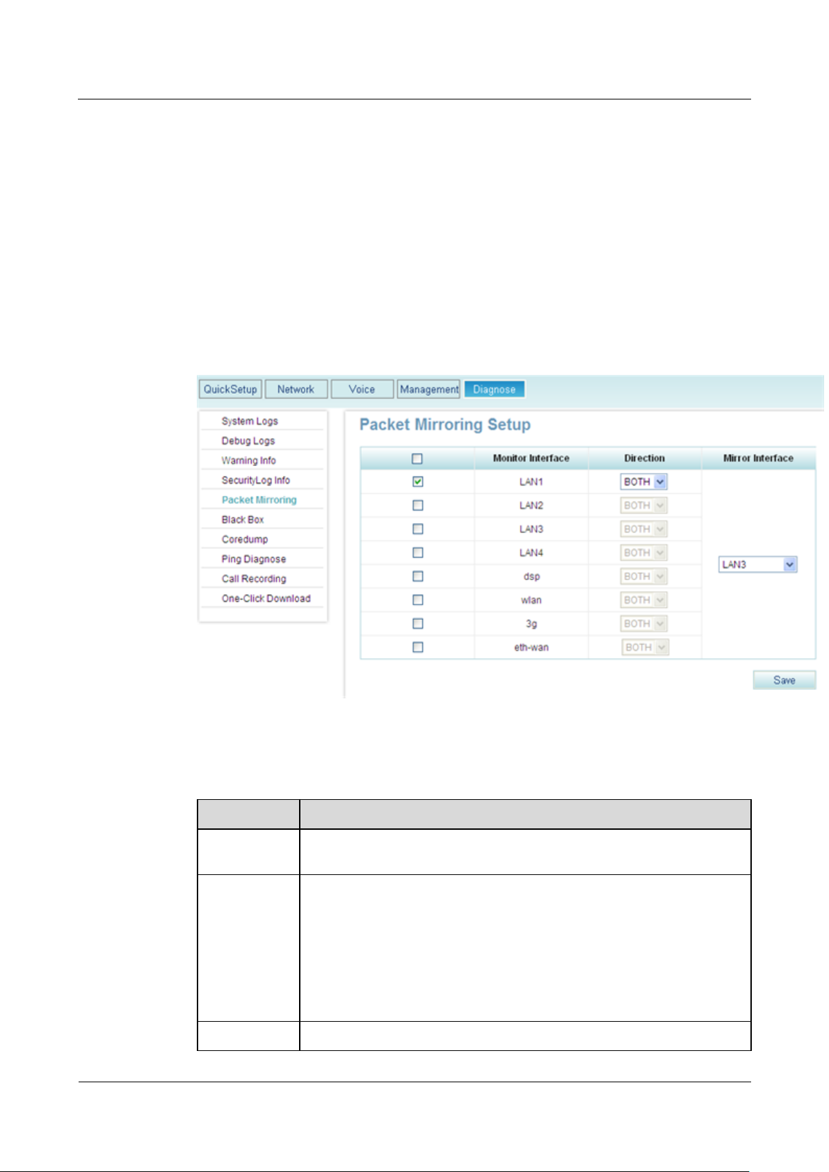
Item
Description
Monitored
port
Port that the mirroring port monitors.
Direction
Direction in which packets are monitored:
IN: Only the packets that the EGW1520 receives on the monitored
port are monitored.
OUT: Only the packets that the EGW1520 sends from the monitored
port are monitored.
BOTH: The packets that the monitored port receives and sends out are
monitored.
Mirroring port
Port that captures packets from the monitored port. As shown in Figure
This section describes how to configure traffic mirroring to capture packets. Traffic mirroring
allows you to use a packet capture tool on the mirroring port to obtain information about
packets entering or leaving the monitored port.
Procedure
Step 1 On the web management system, choose Diagnose > Packet Mirroring from the navigation
tree.
The page shown in Figure 8-2 is displayed.
Figure 8-2 Traffic mirroring
Step 2 Set parameters according to Table 8-2.
Table 8-2 Parameters
eSpace EGW1520 Enterprise Gateway
Product Documentation
8 Diagnosis Mode
Issue 01 (2012-05-15)
Huawei Proprietary and Confidential
Copyright © Huawei Technologies Co., Ltd.
375
Item
Description
8-2, interface LAN3 captures the incoming and outgoing packets on
interface LAN1.
NOTE
Manage the captured packets carefully.
Step 3 Click to save the settings.
----End
8.3 Downloading Black Box Files
This topic describes how to download black box files.
Critical or minor defects that occur during the EGW1520 running process are recorded in
black box files. You can view black box files to analyze system exceptions.
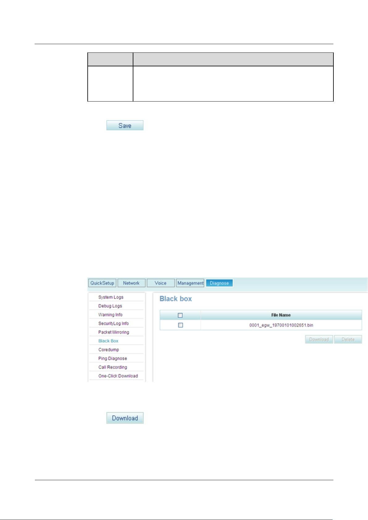
Procedure
Step 1 On the web management system, choose Diagnose > Black Box from the navigation tree.
The page shown in Figure 8-3 is displayed.
Figure 8-3 Downloading black box files
Step 2 Select a black box file to download.
Step 3 Click to save the file to the local host or other hosts on the network as
prompted.
eSpace EGW1520 Enterprise Gateway
Product Documentation
8 Diagnosis Mode
Issue 01 (2012-05-15)
Huawei Proprietary and Confidential
Copyright © Huawei Technologies Co., Ltd.
376
To delete a black box file, select the file and click .
----End
8.4 Pinging IP Addresses
This topic describes how to ping an IP address. Using the ping function, you can ping the peer
device of the EGW1520 to check the connection between them.
Procedure
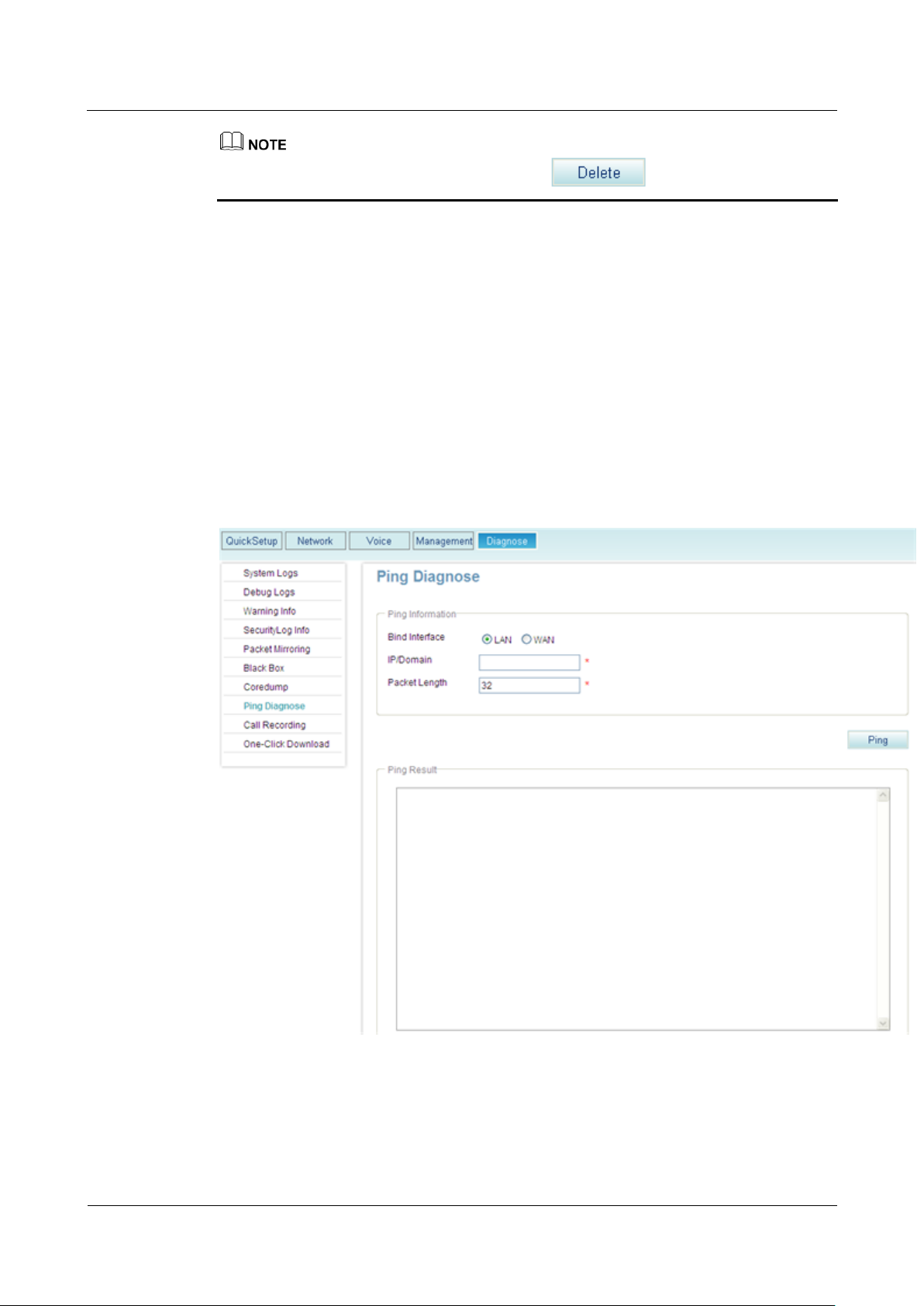
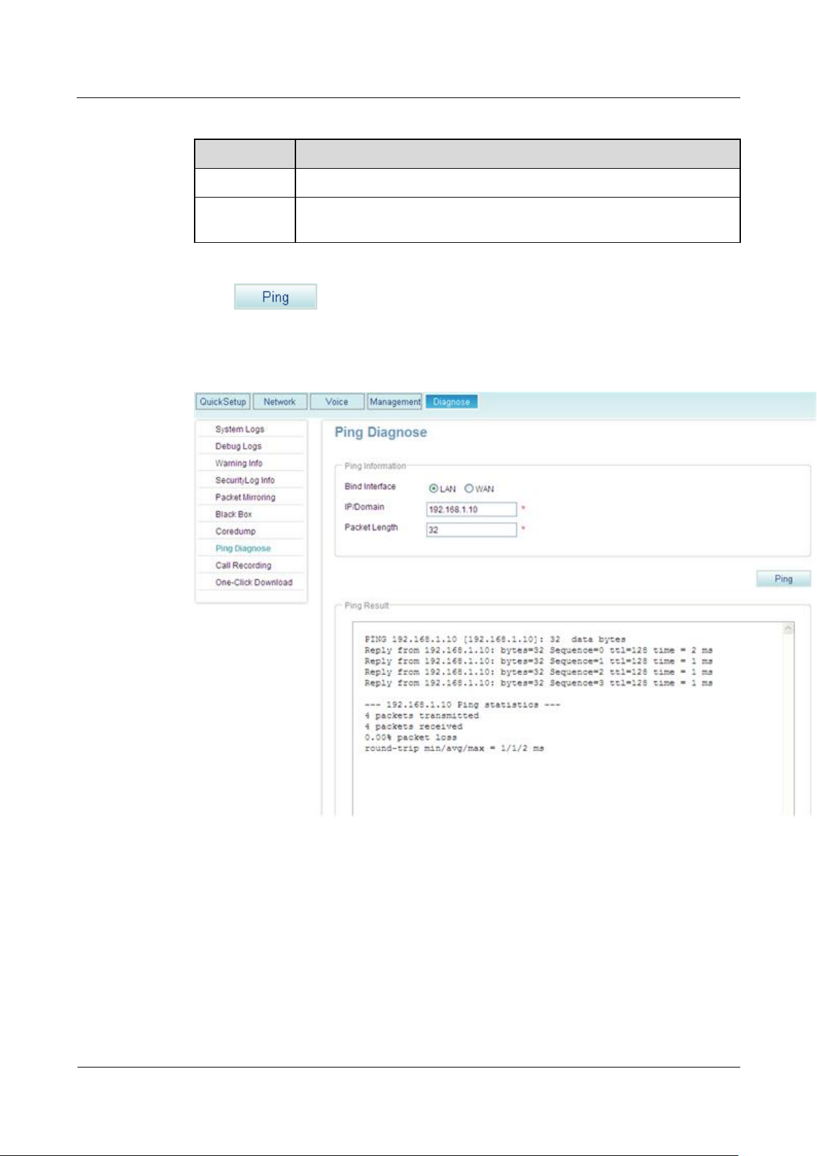
Step 1 On the web management system, choose Diagnose > Ping Diagnose from the navigation tree.
The page shown in Figure 8-4 is displayed.
Figure 8-4 IPPing Diagnose page
Step 2 Select Bind Interface.
Step 3 Set parameters according to Table 8-3.
eSpace EGW1520 Enterprise Gateway
Product Documentation
8 Diagnosis Mode
Issue 01 (2012-05-15)
Huawei Proprietary and Confidential
Copyright © Huawei Technologies Co., Ltd.
377
Table 8-3 Parameter settings
Parameter
Description
IP/Domain
The IP address that will be pinged.
Packet Length
Size of packets that are sent during the ping operation. The packet size
ranges from 20 bytes to 1500 bytes.
Step 4 Click .
The page shown in Figure 8-5 is displayed.
Figure 8-5 Diagnosis result
----End

eSpace EGW1520 Enterprise Gateway
Product Documentation
9 System Management
Issue 01 (2012-05-15)
Huawei Proprietary and Confidential
Copyright © Huawei Technologies Co., Ltd.
378
About This Chapter
This topic describes how to manage and maintain the EGW1520 in different modes.
9.1 Configuring the System Time
This topic describes how to configure the system time manually and how to synchronize the
NTP server time.
9 System Management
9.2 Managing the Configuration File
This topic describes how to back up and load the configuration file.
9.3 Restoring Factory Settings
This topic describes how to restore factory settings.
9.4 Managing System Logs
This topic describes how to manage system logs.
9.5 Viewing Alarms
This topic describes how to view alarms. You can analyze the exceptions occur during system
running according to the alarms.
9.6 Viewing Security Logs
This topic describes how to view security logs to query the recent operations.
9.7 Viewing Electronic Labels
You can learn about the device information based on its electronic label.
9.8 Downloading Call Records
This topic describes how to back up call records on the local computer.
9.9 One-Click Download
This topic describes how to use the one-click download function to collect system information.
If the system is faulty, you can download system information and send it to the maintenance
personnel for fault location.
9.10 Changing the Password

eSpace EGW1520 Enterprise Gateway
Product Documentation
9 System Management
Issue 01 (2012-05-15)
Huawei Proprietary and Confidential
Copyright © Huawei Technologies Co., Ltd.
379
This topic describes how to change the password for logging in to the EGW1520.
9.11 Upgrading Host Software
This topic describes how to upgrade host software.
9.12 Uploading Voice Files
This topic describes how to upload voice files.
9.13 Restarting the EGW1520
This topic describes how to restart the EGW1520.
9.1 Configuring the System Time
This topic describes how to configure the system time manually and how to synchronize the
NTP server time.
The EGW1520 requires correct time to report alarms, trace malicious calls, and generate logs.
The EGW1520 allows you to configure the system time in either of the following modes:
Configure time manually on the local computer. For details, see Configuring Local Time.
− Sets system time on the web management system.
− Supports setting time zones and daylight saving time (DST).
Synchronize time automatically by using the NTP server. For details, see Configuring
NTP Time.
NTP functions at the application layer. Based on the IP and the User Datagram Format
(UDP), the NTP is used to synchronize the time between distributed time servers and
clients. As the EGW1520 supports the NTP protocol, it can function as an NTP client to
synchronize time with the NTP server.
Configuring Local Time
Step 1 On the web management system, choose Management > Date & Time from the navigation
tree.
The page shown in Figure 9-1 is displayed.

eSpace EGW1520 Enterprise Gateway
Product Documentation
9 System Management
Issue 01 (2012-05-15)
Huawei Proprietary and Confidential
Copyright © Huawei Technologies Co., Ltd.
380
Figure 9-1 Date & Time tab page (1)
Parameter
Description
Time zone Offset
Set the time zone.
GMT+: east of GMT
GMT-: west of GMT
For example, set this parameter to GMT+ and 08:00 (GMT+8 time
zone).
Step 2 Set EGW1520 Time as required.
Step 3 Click to save the settings.
When the EGW1520 restarts, the system time that you configure is restored to the default
setting (such as 1970-01-01 00:00:00).
Step 4 (Optional) Configure the time zone.
1. Set parameters according to Table 9-1.
Table 9-1 Parameter description (1)
2. Click to save the settings.
Step 5 (Optional) Configure the DST.
1. Click Daylight Saving Time.
The page shown in Figure 9-2 is displayed.

eSpace EGW1520 Enterprise Gateway
Product Documentation
9 System Management
Issue 01 (2012-05-15)
Huawei Proprietary and Confidential
Copyright © Huawei Technologies Co., Ltd.
381
Figure 9-2 Configuring the DST
Parameter
Description
Start By
Start type of the DST.
Date: The start time is a date.
Day: The start time is a day in a week.
End By
End type of the DST.
Date: The end time is a date.
Day: The end time is a day in a week.
Start Time
DST start time.
End Time
DST end time.
Start Week
Week counting from the start time. This parameter is valid when
Type is set to Start Day.
End Week
Week counting from the end time. This parameter is valid when
Type is set to End Day.
Start Weekday
Day in a week counting from the start time. This parameter is valid
when Type is set to Start Day.
End Weekday
Day in a week counting backward from the end time. This
parameter is valid when Type is set to End Day.
Time Offset (min)
DST offset. If the DST function is enabled, the system time is the
original time plus the offset within the validity period of the DST.
2. Set parameters according to Table 9-2.
Table 9-2 Parameter description (2)
3. Click to save the settings.

eSpace EGW1520 Enterprise Gateway
Product Documentation
9 System Management
Issue 01 (2012-05-15)
Huawei Proprietary and Confidential
Copyright © Huawei Technologies Co., Ltd.
382
----End
Parameter
Description
Main NTP Server
IP address or domain name of the active NTP server.
Sub NTP Server
IP address or domain name of the standby NTP server.
Synchronization Interval
Period of synchronizing the NTP server time.
Configuring NTP Time
Step 1 On the web management system, choose Management > Date & Time from the navigation
tree.
Step 2 Click the NTP Server tab.
Step 3 Click Network Time Synchronization Service.
The page shown in Figure 9-3 is displayed.
Figure 9-3 Configuring the NTP server
Step 4 Set parameters according to Table 9-3.
Table 9-3 Parameter description (3)

eSpace EGW1520 Enterprise Gateway
Product Documentation
9 System Management
Issue 01 (2012-05-15)
Huawei Proprietary and Confidential
Copyright © Huawei Technologies Co., Ltd.
383
Parameter
Description
(s)
Synchronization Status
Status of NTP server time synchronization.
Encryption Type
The value is the same as that of the NTP server.
Authentication Key ID
The value is the same as that of the NTP server.
Password
The value is the same as that of the NTP server.
Step 5 Click to save the settings.
Check whether the NTP server time is the same as the EGW1520 time on the Date & Time
tab page. If yes, the NTP server time synchronization is successful.
----End
9.2 Managing the Configuration File
This topic describes how to back up and load the configuration file.
During routine maintenance, configuration data may be missing due to abnormal device
restart or upgrade failure. Therefore, you are advised to back up the configuration file
periodically.
After backup is complete, you can load the configuration file as required to recover data.
The EGW1520 allows you to back up and load the configuration file in web mode. You can:
Back up the configuration file, which contains all the configurable data and can be
encrypted. For details, see Backing Up the Configuration File.
Load the configuration file in HTTP mode. For details, see Loading the Configuration
File (HTTP).
Load the configuration file in FTP mode. For details, see Loading the Configuration File
(FTP).
Load the configuration file in TFTP mode. For details, see Loading the Configuration
File (TFTP).
Load the configuration file in FTPS mode. For details, see Loading the Configuration
File (FTPS).
In FTP mode, data is transmitted in plain text. Load configuration files in FTP mode on
trusted networks.

eSpace EGW1520 Enterprise Gateway
Product Documentation
9 System Management
Issue 01 (2012-05-15)
Huawei Proprietary and Confidential
Copyright © Huawei Technologies Co., Ltd.
384
Backing Up the Configuration File
Step 1 On the web management system, choose Management > Configuration from the navigation
tree.
The page shown in Figure 9-4 is displayed.
Figure 9-4 Backing up the configuration file
Step 2 (Optional) Select Encrypt Configuration File to encrypt the configuration file.
Step 3 Click to back up the configuration file to the local host or other hosts on the
network as prompted.
The configuration file is in .xml format. The default file name is in CFG+WAN port's MAC
address.xml, for example, CFG001882ab2415.xml. You can also change the file name.
----End
Loading the Configuration File (HTTP)
Step 1 On the web management system, choose Management > Configuration from the navigation
tree.
Step 2 Click the Update tab.
The page shown in Figure 9-5 is displayed.

eSpace EGW1520 Enterprise Gateway
Product Documentation
9 System Management
Issue 01 (2012-05-15)
Huawei Proprietary and Confidential
Copyright © Huawei Technologies Co., Ltd.
385
Figure 9-5 Loading the configuration file (HTTP)
Step 3 Click Browse and select a configuration file.
Set the file path, which can be a local path, for example, D:\CFG001882ab2415.xml, or a
network path, for example, \\10.168.10.111\CFG001882ab2415.xml.
Step 4 Click and proceed as prompted.
After loading is successful, the EGW1520 automatically restarts. After the restart is complete,
you can log in to the EGW1520 web management system.
The restart takes 2 to 3 minutes depending on the device configuration. If the
configuration data is more, the startup time is longer.
If the uploading fails, the configuration data on the EGW1520 remains. You can reload the
configuration file.
After the LAN port restarts, the management IP address changes to the imported IP
address.
----End
Loading the Configuration File (FTP)
Step 1 On the web management system, choose Management > Configuration from the navigation
tree.
Step 2 Click the Update tab.
Step 3 Click FTP.
The page shown in Figure 9-6 is displayed.

eSpace EGW1520 Enterprise Gateway
Product Documentation
9 System Management
Issue 01 (2012-05-15)
Huawei Proprietary and Confidential
Copyright © Huawei Technologies Co., Ltd.
386
Figure 9-6 Loading the configuration file (FTP)
Parameter
Description
FTP Server
IP address of the FTP server.
NOTE
Ensure that the FTP service is enabled when configuration files are loaded and that
the FTP server connects to the EGW1520 properly.
File Name
Relative path of the file to be uploaded. If the configuration file is stored
in C:/ftp/egw/CFG001882ab2415.xml and the access path that is set on
the FTP server is C:/ftp, set the relative path to
egw/CFG001882ab2415.xml.
Port Number
Port number of the FTP server, which is 21 by default.
Anonymous
If you select Anonymous, the EGW1520 connects to the FTP server as
an anonymous user that is the default user on the FTP server.
User Name
User name for logging in to the FTP server. This parameter is configured
on the FTP server.
Password
Password for logging in to the FTP server. This parameter is configured
on the FTP server.
Step 4 Set parameters according to Table 9-4.
Table 9-4 FTP parameters
Step 5 Click and proceed as prompted.

eSpace EGW1520 Enterprise Gateway
Product Documentation
9 System Management
Issue 01 (2012-05-15)
Huawei Proprietary and Confidential
Copyright © Huawei Technologies Co., Ltd.
387
After loading is successful, the EGW1520 automatically restarts. After the restart is complete,
Parameter
Description
TFTP Server
IP address of the TFTP server.
NOTE
you can log in to the EGW1520 web management system.
The restart takes 2 to 3 minutes depending on the device configuration. If the
configuration data is more, the startup time is longer.
If the uploading fails, the configuration data on the EGW1520 remains. You can reload the
configuration file.
After the LAN port restarts, the management IP address changes to the imported IP
address.
----End
Loading the Configuration File (TFTP)
Step 1 On the web management system, choose Management > Configuration from the navigation
tree.
Step 2 Click the Update tab.
Step 3 Click TFTP.
The page shown in Figure 9-7 is displayed.
Figure 9-7 Loading the configuration file (TFTP)
Step 4 Set parameters according to Table 9-5.
Table 9-5 TFTP parameters

eSpace EGW1520 Enterprise Gateway
Product Documentation
9 System Management
Issue 01 (2012-05-15)
Huawei Proprietary and Confidential
Copyright © Huawei Technologies Co., Ltd.
388
Parameter
Description
Ensure that the TFTP service is enabled when configuration files are loaded
and that the TFTP server connects to the EGW1520 properly.
File Name
Relative path of the file to be uploaded. If the configuration file is
stored in C:/tftp/egw/CFG001882ab2415.xml and the access path
that is set on the TFTP server is C:/tftp, set the relative path to
egw/CFG001882ab2415.xml.
Port Number
Port number of the TFTP server, which is 69 by default.
Step 5 Click and proceed as prompted.
After loading is successful, the EGW1520 automatically restarts. After the restart is complete,
you can log in to the EGW1520 web management system.
The restart takes 2 to 3 minutes depending on the device configuration. If the
configuration data is more, the startup time is longer.
If the uploading fails, the configuration data on the EGW1520 remains. You can reload the
configuration file.
After the LAN port restarts, the management IP address changes to the imported IP
address.
----End
Loading the Configuration File (FTPS)
Step 1 On the web management system, choose Management > Configuration from the navigation
tree.
Step 2 Click the Update tab.
Step 3 Click FTPS.
The page shown in Figure 9-8 is displayed.

eSpace EGW1520 Enterprise Gateway
Product Documentation
9 System Management
Issue 01 (2012-05-15)
Huawei Proprietary and Confidential
Copyright © Huawei Technologies Co., Ltd.
389
Figure 9-8 Loading the configuration file (FTPS)
Parameter
Description
FTPS Server
IP address of the FTPS server.
NOTE
Ensure that the FTPS service is enabled when configuration files are loaded and that
the TFTP server connects to the EGW1520 properly.
File Name
Relative path of the file to be uploaded. If the configuration file is stored in
C:/ftps/egw/CFG001882ab2415.xml and the access path that is set on the
FTP server is C:/ftps, set the relative path to
egw/CFG001882ab2415.xml.
Port Number
Port number of the FTPS server. The default port number is 990.
Anonymous
If Anonymous is selected, the EGW1520 connects to the FTPS server as
an anonymous user.
User Name
User name for logging in to the FTPS server. This parameter is configured
on the FTPS server.
Password
Password for logging in to the FTPS server. This parameter is configured
on the FTPS server.
Certificates
Certificate for authenticate logins.
NOTE
Before using the certificate to authenticate logins, configure the certificate by
Step 4 Set parameters according to Table 9-6.
Table 9-6 FTPS parameters

eSpace EGW1520 Enterprise Gateway
Product Documentation
9 System Management
Issue 01 (2012-05-15)
Huawei Proprietary and Confidential
Copyright © Huawei Technologies Co., Ltd.
390
Parameter
Description
referring to 7.5.7 Certificate.
Step 5 Click and proceed as prompted.
After loading is successful, the EGW1520 automatically restarts. After the restart is complete,
you can log in to the EGW1520 web management system.
The restart takes 2 to 3 minutes depending on the device configuration. If the
configuration data is more, the startup time is longer.
If the uploading fails, the configuration data on the EGW1520 remains. You can reload the
configuration file.
After the LAN port restarts, the management IP address changes to the imported IP
address.
----End
9.3 Restoring Factory Settings
This topic describes how to restore factory settings.
Before restoring factory settings, refer 9.2 Managing the Configuration File to back up the
configuration information of the current version.
After restoration, the EGW1520 restarts automatically to make the factory settings take effect.
To view factory settings, log in to the web management system again.
To restore factory settings, press the RESET button on the device or perform operations on
the web page.
RESET Button
Press RESET on the EGW1520 for longer than six seconds.
Web Mode
Step 1 On the web, choose Management > Restore Default from the navigation tree.
The page shown in Figure 9-9 is displayed.

eSpace EGW1520 Enterprise Gateway
Product Documentation
9 System Management
Issue 01 (2012-05-15)
Huawei Proprietary and Confidential
Copyright © Huawei Technologies Co., Ltd.
391
Figure 9-9 Restore page
Step 2 Click and proceed as prompted.
After the EGW1520 restarts, the configuration data changes to factory settings. Use the IP
address 192.168.1.1, the user name admin and the password Admin@123 to log in to the
web management system again, see 7.7.1 Web Management.
----End
9.4 Managing System Logs
This topic describes how to manage system logs.
During the EGW1520 running, a large number of logs are generated and sent to the syslog
management module. You can send the log file to the Huawei technical support for faults
analysis. The EGW1520 provides the following log functions:
Backs up the log file remotely.
If the remote backup function is configured, the syslog management module sends the
log file to the log server for your remote maintenance. For details, see Backing Up Log
Files Remotely.
Backs up the log file locally.
If the local backup function is configured, the log file is saved in the local flash memory.
The EGW1520 allows you to download the latest log files from the flash memory on a
web page. For details, see Backing Up the Log File Locally.
The EGW1520 writes the flash memory when a 512 KB log is generated. When the size of
generated logs reaches 2 MB, the earliest logs are overwritten by the latest ones.
Sets the log level.

eSpace EGW1520 Enterprise Gateway
Product Documentation
9 System Management
Issue 01 (2012-05-15)
Huawei Proprietary and Confidential
Copyright © Huawei Technologies Co., Ltd.
392
Parameter
Description
Log Level
The options are as follows:
Emergency: Error log, which indicates that a critical fault occurs
and the system cannot be recovered.
Alert: Error log, which indicates that a severe fault occurs and
must be rectified immediately.
Critical: Error log, which indicates that a major fault occurs.
Error: Error log, which indicates that a minor fault occurs.
Warning: Warning log, which indicates that certain functions are
Configuring Logs
Prerequisite
The log service has been started on the log server. The log path and log file name have been
set.
Configuration Procedure
Step 1 On the web management system, choose Diagnose > System Logs from the navigation tree.
The page shown in Figure 9-10 is displayed.
Figure 9-10 Enabling the function of generating logs
Deletes the log file.
You can delete the log file in the local flash memory in web mode. For details, see
Deleting Logs.
Step 2 Set log levels according to Table 9-7.
Table 9-7 Log level

eSpace EGW1520 Enterprise Gateway
Product Documentation
9 System Management
Issue 01 (2012-05-15)
Huawei Proprietary and Confidential
Copyright © Huawei Technologies Co., Ltd.
393
Parameter
Description
unavailable.
Notice: Notification log, which indicates that a major event
occurs.
Informational: Informational log, which indicates common events
and status information
Debugging: Debug log, which records information about system
internal debugging.
NOTE
To generate debug logs, set the log level to Debugging and enable the debug
log for each module. For details, see 8.1 Enabling the Debug Log.
The EGW1520 only sends log information whose level is equal to or higher than that you set
to the log server. The highest level is Emergency and the lowest level is Debugging.
Step 3 Click to save the settings.
----End
Backing Up Log Files Remotely
Step 1 Enable the function of generating logs. For details, see Configuring Logs.
Step 2 Set Mode to Remote.
The page shown in Figure 9-11 is displayed.

eSpace EGW1520 Enterprise Gateway
Product Documentation
9 System Management
Issue 01 (2012-05-15)
Huawei Proprietary and Confidential
Copyright © Huawei Technologies Co., Ltd.
394
Figure 9-11 Remote backup
Parameter
Description
Mode
Log backup mode. The options are as follows:
Local: Saves the log file to the local computer.
Remote: Sends the log file to the remote log server.
Both: Sends the log file to the local computer and the remote log
server.
Server IP Address
IP address of the log server. Set this parameter when Mode is set to
Remote or Both.
Server UDP Port
Port number of the log server. Set this parameter when Mode is set to
Remote or Both. The default value is 514.
Step 3 Set parameters according to Table 9-8.
Table 9-8 Parameter description
Step 4 Click to save the settings.
The log file is automatically sent to the log server.
----End
Backing Up the Log File Locally
Step 1 Enable the function of generating logs. For details, see Configuring Logs.
Step 2 Set Mode to Local.

eSpace EGW1520 Enterprise Gateway
Product Documentation
9 System Management
Issue 01 (2012-05-15)
Huawei Proprietary and Confidential
Copyright © Huawei Technologies Co., Ltd.
395
The page shown in Figure 9-12 is displayed.
Figure 9-12 Local backup
Step 3 Click to save the settings.
The log file will be automatically saved to the local flash memory.
----End
Downloading Logs
Step 1 Enable the function of generating logs. For details, see Configuring Logs.
The page shown in Figure 9-13 is displayed.
Figure 9-13 Downloading logs
Step 2 Click , and back up log files to the local host or other hosts on the network as
prompted.

eSpace EGW1520 Enterprise Gateway
Product Documentation
9 System Management
Issue 01 (2012-05-15)
Huawei Proprietary and Confidential
Copyright © Huawei Technologies Co., Ltd.
396
Deleting Logs
Step 1 Enable the function of generating logs. For details, see Configuring Logs.
The log file is in .log format. The default file name is in Log+Current EGW1520 system date.log
format, for example, Log20100101.log. You can also change the file name.
After downloading the log file, you can delete the log file from the flash memory according to
Deleting Logs.
----End
You can delete old logs from the flash memory.
Log information that is sent to the log server is not affected.
The page shown in Figure 9-14 is displayed.
Figure 9-14 Deleting logs
Step 2 Click and proceed as prompted.
----End
9.5 Viewing Alarms
This topic describes how to view alarms. You can analyze the exceptions occur during system
running according to the alarms.
Procedure
Step 1 On the web management system, choose Diagnose > Warning Info from the navigation tree.
The page shown in Figure 9-15 is displayed.

eSpace EGW1520 Enterprise Gateway
Product Documentation
9 System Management
Issue 01 (2012-05-15)
Huawei Proprietary and Confidential
Copyright © Huawei Technologies Co., Ltd.
397
Figure 9-15 Alarms
Step 2 Click to save the file to the local host or other hosts on the network as
prompted.
To delete all alarms, click .
----End
9.6 Viewing Security Logs
This topic describes how to view security logs to query the recent operations.

eSpace EGW1520 Enterprise Gateway
Product Documentation
9 System Management
Issue 01 (2012-05-15)
Huawei Proprietary and Confidential
Copyright © Huawei Technologies Co., Ltd.
398
Procedure
Step 1 Choose Diagnose > SecurityLog Info from the navigation tree.
When automatic software upgrade is configured, the system generates security logs only for the first
upgrade.
A page shown in Figure 9-16 is displayed.
Figure 9-16 Viewing security logs
Step 2 Click and back up log files to the local host or other hosts on the network as
prompted.
To delete all security logs, click . Only network administrators can delete all security
logs.
Log sample
A log sample is as follows:
User ID: 192.168.1.8
Log type: alarmlog
Time: 1970–01–01 01:28:30

eSpace EGW1520 Enterprise Gateway
Product Documentation
9 System Management
Issue 01 (2012-05-15)
Huawei Proprietary and Confidential
Copyright © Huawei Technologies Co., Ltd.
399
Log information: Downloaded alarm logs succeed
The following is a detailed description of the preceding log sample:
admin/192.168.1.8: The user name is admin and the user ID is 192.168.1.8.
alarmlog: This log is an alarm log.
1970–01–01 01:28:30: Time when this operation is performed.
Downloaded alarm logs succeed: This alarm log is downloaded successfully.
For details about the security log information, see 12.2 Security Log Information.
----End
9.7 Viewing Electronic Labels
You can learn about the device information based on its electronic label.
To view the electronic label of a device, perform the following operations:
Step 1 You have logged in to the web management system. For details, see 7.7.1 Web Management
Step 2 Choose Management > Status > from the navigation tree.
The system displays a page, as shown in Figure 9-17.
Figure 9-17 Electronic label (1)
Step 3 Click Electronic Label .
The system displays a page, as shown in Figure 9-18.

eSpace EGW1520 Enterprise Gateway
Product Documentation
9 System Management
Issue 01 (2012-05-15)
Huawei Proprietary and Confidential
Copyright © Huawei Technologies Co., Ltd.
400
Figure 9-18 Electronic label (2)
Parameter
Meaning
BoardType
Model of the field replaceable unit (FRU).
BarCode
Bar code of the FRU, which is the same as the device bar code.
Item
BBOM code of the FRU.
Description
Description of the FRU.
Manufactured
Manufacture date of the FRU.
VendorName
Vendor name of the FRU.
IssueNumber
Issue number of the FRU.
CLEICode
CLEI code of the FRU.
BOM
Specific item code of the FRU.
Table 9-9 describes the parameters in the electronic label information.
Table 9-9 Description of electronic label parameters
The physical label is affixed to he bottom of the device.
----End

eSpace EGW1520 Enterprise Gateway
Product Documentation
9 System Management
Issue 01 (2012-05-15)
Huawei Proprietary and Confidential
Copyright © Huawei Technologies Co., Ltd.
401
9.8 Downloading Call Records
This topic describes how to back up call records on the local computer.
The call record backup function has the following features:
Saves the latest 5000 records. When the number of saved call records reaches 5,000, the
system overwrites the earliest call records to save the latest ones.
Saves 40 call records each time. If the number of latest call records is smaller than 40,
the system saves call records at an interval of four hours.
Saves the call start and end time, and the calling and called numbers.
Configuration procedure
Step 1 On the web management system, choose Diagnose > Call Recording from the navigation
tree.
Step 2 Set Call Recording to Enable.
The page shown in Figure 9-19 is displayed.
Figure 9-19 Downloading call records
By default, the system disables the call record backup function.
Step 3 Click to save the settings.
Step 4 Click to download call records that are saved. Download call records to a
local host or other hosts on the network.

eSpace EGW1520 Enterprise Gateway
Product Documentation
9 System Management
Issue 01 (2012-05-15)
Huawei Proprietary and Confidential
Copyright © Huawei Technologies Co., Ltd.
402
The call record file must be in the .txt format. The default file name is in CDR+Current
EGW1520 system date.txt format, for example, CDR20110101.txt. You can also change
the file name.
Click the Delete All Records After Download option button. Then the web management
system will delete call records after the downloading is complete.
----End
9.9 One-Click Download
This topic describes how to use the one-click download function to collect system information.
If the system is faulty, you can download system information and send it to the maintenance
personnel for fault location.
The EGW1520 provides the one-click download function for you to collect the following
information:
System configurations (device model, hardware version, software version, MAC address
on WAN port, IP address on WAN port, and IP address on LAN port)
System logs
Alarm information
Procedure
Step 1 On the web management system, choose Diagnose > One-Click Download from the
navigation tree.
The page shown in Figure 9-20 is displayed.
Figure 9-20 One-click download

eSpace EGW1520 Enterprise Gateway
Product Documentation
9 System Management
Issue 01 (2012-05-15)
Huawei Proprietary and Confidential
Copyright © Huawei Technologies Co., Ltd.
403
Step 2 Click to download information.
Parameter
Description
Use a strong
Password
Indicates whether to set a complicated password. If this parameter is
enabled, the password must contain special characters, such as @, #
and %.
----End
9.10 Changing the Password
This topic describes how to change the password for logging in to the EGW1520.
The EGW1520 allows a maximum of 10 users to log in at the same time.
The new password takes effect upon the next login. When a user changes the password, other
users who have logged in are not affected.
If you forget the password, you can only restore the password to the default factory setting. As
a result, the configuration data is lost.
Procedure
Step 1 On the web management system, choose Management > Change Password from the
navigation tree.
The page shown in Figure 9-21 is displayed.
Figure 9-21 Change Password page
Step 2 Set parameters according to Table 9-10.
Table 9-10 Parameter description

eSpace EGW1520 Enterprise Gateway
Product Documentation
9 System Management
Issue 01 (2012-05-15)
Huawei Proprietary and Confidential
Copyright © Huawei Technologies Co., Ltd.
404
Parameter
Description
User Name
Indicates the user name. The user name is admin and cannot be changed.
Old Password
Indicates the current password.
New Password
Indicates the new password to be set. The password consists of 6 to 16
characters.
Confirm
Password
Indicates that the user enters the new password again.
Step 3 Click to save the settings.
----End
9.11 Upgrading Host Software
This topic describes how to upgrade host software.
The EGW1520 allows you to upgrade the host software on a web page. The following modes
are provided:
HTTP mode
FTP mode
TFTP mode
FTPS mode
Upgrade procedures vary according to version. For details on the host software storage path
and upgrade methods, see the eSpace EGW1520 Upgrade Guide.
If the device is powered off or network communication is interrupted during software upgrade,
the device may crash or the configuration file may be lost.
9.12 Uploading Voice Files
This topic describes how to upload voice files.
Voice files can be uploaded to the EGW1520 to play announcements for users.
The EGW1520E allows you to upload voice files in .pcm format or compressed voice file
packages in .zip format on a web page. The following modes are provided:
HTTP Mode
FTP Mode

eSpace EGW1520 Enterprise Gateway
Product Documentation
9 System Management
Issue 01 (2012-05-15)
Huawei Proprietary and Confidential
Copyright © Huawei Technologies Co., Ltd.
405
HTTP Mode
Step 1 On the web management system, choose Voice > Upload Voice File from the navigation tree.
TFTP Mode
FTPS Mode
By default, Chinese voice files are loaded on the EGW1520. You can choose Voice >
Upload Voice File to change the language.
When uploading a voice file in .pcm format, ensure that the file size is not greater than 1
MB. When uploading a voice file in .zip format, ensure that the file size is not greater than
30 MB.
In FTP mode, data is transmitted in plain text. Load configuration files in FTP mode on
trusted networks.
The page shown in Figure 9-22 is displayed.
Figure 9-22 Upload Voice File page (HTTP)
Step 2 Click Browse and select the voice file to be uploaded.
The voice file path can be a local path, for example, D:\english.zip, or a network path, for
example, \\10.168.10.111\english.zip.
Step 3 Click and proceed as prompted.
After the loading is successful, the Message page is displayed, as shown in Figure 9-23.

eSpace EGW1520 Enterprise Gateway
Product Documentation
9 System Management
Issue 01 (2012-05-15)
Huawei Proprietary and Confidential
Copyright © Huawei Technologies Co., Ltd.
406
FTP Mode
Step 1 On the web management system, choose Voice > Upload Voice File from the navigation tree.
Figure 9-23 Success message
If the loading fails, the voice file on the EGW1520 remains. You can reload the voice file.
----End
Step 2 Click FTP.
The page shown in Figure 9-24 is displayed.
Figure 9-24 Upload Voice File page (FTP)
Step 3 Set parameters according to Table 9-11.

eSpace EGW1520 Enterprise Gateway
Product Documentation
9 System Management
Issue 01 (2012-05-15)
Huawei Proprietary and Confidential
Copyright © Huawei Technologies Co., Ltd.
407
Table 9-11 FTP parameters
Parameter
Description
FTP Server
Indicates the IP address of the FTP server.
NOTE
Ensure that the FTP service is enabled when configuration files are loaded and that
the FTP server connects to the EGW1520 properly.
File Name
Indicates the relative path of the file to be uploaded. If the file to be
uploaded is stored in C:/ftp/egw/voice.zip and the access path that is set on
the FTP server is C:/ftp, set the relative path to egw/voice.zip.
Port Number
Indicates the port number of the FTP server. The default value is 21.
Anonymous
If you select Anonymous, the EGW1520 connects to the FTP server as an
anonymous user that is the default user on the FTP server.
User Name
Indicates the user name for logging in to the FTP server. This parameter is
configured on the FTP server.
Password
Indicates the password for logging in to the FTP server. This parameter is
configured on the FTP server.
Step 4 Click and proceed as prompted.
After the loading is successful, the Message page is displayed, as shown in Figure 9-25.
Figure 9-25 Success message
If the loading fails, the voice file on the EGW1520 remains. You can reload the voice file.
----End
TFTP Mode
Step 1 On the web page's navigation bar, choose Voice > Upload Voice File.
Step 2 Click TFTP.
The page shown in Figure 9-26 is displayed.

eSpace EGW1520 Enterprise Gateway
Product Documentation
9 System Management
Issue 01 (2012-05-15)
Huawei Proprietary and Confidential
Copyright © Huawei Technologies Co., Ltd.
408
Figure 9-26 Upload Voice File page (TFTP)
Parameter
Description
TFTP Server
Indicates the IP address of the TFTP server.
NOTE
Ensure that the TFTP service is enabled when configuration files are loaded and
that the TFTP server connects to the EGW1520 properly.
File Name
Indicates the relative path of the file to be uploaded. If the file to be
uploaded is stored in C:/tftp/egw/voice.zip and the access path that is
set on the FTP server is C:/tftp, set the relative path to egw/voice.zip.
Port Number
Indicates the port number of the TFTP server, which is 69 by default.
Step 3 Set parameters according to Table 9-12.
Table 9-12 TFTP parameters
Step 4 Click and proceed as prompted.
After the loading is successful, the Message page is displayed, as shown in Figure 9-27.
Figure 9-27 Success message

eSpace EGW1520 Enterprise Gateway
Product Documentation
9 System Management
Issue 01 (2012-05-15)
Huawei Proprietary and Confidential
Copyright © Huawei Technologies Co., Ltd.
409
FTPS Mode
Parameter
Description
FTPS Server
IP address of the FTPS server.
NOTE
Ensure that the FTPS service is enabled when configuration files are loaded and
that the TFTP server connects to the EGW1520 properly.
File Name
Indicates the relative path of the file to be uploaded. If the file to be
uploaded is stored in C:/ftps/egw/voice.zip and the access path that is
Step 1 On the web page's navigation bar, choose Voice > Upload Voice File.
Step 2 Click FTPS.
If the loading fails, the voice file on the EGW1520 remains. You can reload the voice file.
----End
The page shown in Figure 9-28 is displayed.
Figure 9-28 Upload Voice File page (FTPS)
Step 3 Set parameters according to Table 9-13.
Table 9-13 FTPS parameters

eSpace EGW1520 Enterprise Gateway
Product Documentation
9 System Management
Issue 01 (2012-05-15)
Huawei Proprietary and Confidential
Copyright © Huawei Technologies Co., Ltd.
410
Parameter
Description
set on the FTPS server is C:/ftps, set the relative path to egw/voice.zip.
Port Number
Port number of the FTPS server. The default port number is 990.
Anonymous
If Anonymous is selected, the EGW1520 connects to the FTPS server as
an anonymous user.
User Name
Indicates the user name for logging in to the FTPS server. This
parameter is configured on the FTPS server.
Password
Indicates the password for logging in to the FTPS server. This parameter
is configured on the FTPS server.
Certificates
Certificate for authenticate logins.
NOTE
Before using the certificate to authenticate logins, configure the certificate by
referring to 7.5.7 Certificate.
Step 4 Click and proceed as prompted.
After the loading is successful, the Message page is displayed, as shown in Figure 9-29.
Figure 9-29 Success message
If the loading fails, the voice file on the EGW1520 remains. You can reload the voice file.
----End
9.13 Restarting the EGW1520
This topic describes how to restart the EGW1520.
You can restart the EGW1520 on the web page or pressing the RESET button on the device.
RESET Button
Press RESET on the EGW1520 for six seconds or shorter.

eSpace EGW1520 Enterprise Gateway
Product Documentation
9 System Management
Issue 01 (2012-05-15)
Huawei Proprietary and Confidential
Copyright © Huawei Technologies Co., Ltd.
411
Web Mode
Step 1 On the web management system, choose Management > Restart from the navigation tree.
The page shown in Figure 9-30 is displayed.
Figure 9-30 Restart page
Step 2 Click and proceed as prompted.
The restart takes 2 to 3 minutes depending on the device configuration. More configurations
indicate a longer restart duration. Access the web management system to check whether the
restart is complete. The restart is complete if you can access the page.
----End

eSpace EGW1520 Enterprise Gateway
Product Documentation
10 Security Maintenance
Issue 01 (2012-05-15)
Huawei Proprietary and Confidential
Copyright © Huawei Technologies Co., Ltd.
412
About This Chapter
This topic describes the concept and methods for maintaining the EGW1520.
10.1 Overview
10.2 Application Layer Security
10 Security Maintenance
10.3 System Layer Security
10.4 Network Layer Security
10.5 Management Layer Security
10.6 Appendix
10.1 Overview
10.1.1 Objectives
Application systems are facing growing security threats. If a security problem occurs, services
will be interrupted, profits will decrease, and the system may break down. To detect potential
security problems and resolve them in time, users need to establish an all-round protection
system and execute maintenance tasks with a hierarchical approach.
As new security threats emerge continuously, technical methods are insufficient to ensure the
security of application systems. Therefore, users also need to develop a security management
system based on the suggestions given on problems found in routine security maintenance,
which ensures proper running of the applications.
10.1.2 Layered Security Maintenance
Based on the security maintenance objects and objectives, security maintenance on service
systems must be conducted at different layers.
Application Layer
The security maintenance at this layer is conducted to ensure that the EGW1520 and related
web management system run properly and provide services correctly.

eSpace EGW1520 Enterprise Gateway
Product Documentation
10 Security Maintenance
Issue 01 (2012-05-15)
Huawei Proprietary and Confidential
Copyright © Huawei Technologies Co., Ltd.
413
System layer
Security maintenance at this layer is conducted to ensure that the operating system runs
properly, ensuring the proper running of applications at the application layer.
At the system layer, security maintenance is conducted using the maintenance terminals or
tools corresponding to the maintenance objects.
Network Layer
Security maintenance at this layer is conducted to ensure the proper running of switches,
routers, and firewalls and to ensure the application of security policies at this layer.
At the network layer, security maintenance is conducted using the maintenance terminals or
tools of the maintenance objects.
Management layer
Security maintenance at this layer is conducted to enhance manual management and
maintenance to prevent potential risks. The preceding layers are involved in
management-layer security maintenance.
10.1.3 EGW1520 Security Overview
This topic describes the EGW1520 security solution.
Security is essential to communications products and systems. The EGW1520 security
solution contains the following layers:
The security at the management layer ensures the system maintenance, running, security,
and continuity.
The security at the application layer protects all Huawei applications, including access,
data, communication, and coding.
Security at the system layer protects the operating systems, databases, and middleware
used by applications.
The security of the network layer protects the network devices and communication.
With the cooperation of the four layers, the EGW1520 security solution provides security
protection for small-sized enterprises.
Figure 10-1 shows the layered architecture of the EGW1520 security solution.

eSpace EGW1520 Enterprise Gateway
Product Documentation
10 Security Maintenance
Issue 01 (2012-05-15)
Huawei Proprietary and Confidential
Copyright © Huawei Technologies Co., Ltd.
414
Figure 10-1 Layered architecture of the EGW1520 security solution
User Name
Default
Password
Function
Remarks
admin
Admin@12
3
Account for logging in to the
web management system.
The user name and password
are both case sensitive. The
user name and rights cannot
be changed.
10.2 Application Layer Security
10.2.1 Application Layer Account Management
Accounts at the application layer
Table 10-1 listed the accounts at the application layer.
Table 10-1 Accounts at the application layer
Password Principle
The login password must contain at least six digits.

eSpace EGW1520 Enterprise Gateway
Product Documentation
10 Security Maintenance
Issue 01 (2012-05-15)
Huawei Proprietary and Confidential
Copyright © Huawei Technologies Co., Ltd.
415
The login password and service (for example, voice mailbox) password cannot be
displayed on GUIs in clear text, and must be encrypted before they are stored.
Before changing a password, you must enter the original password.
Changing a Password
Step 1 On the web management system, choose Management > Change Password from the
navigation tree.
The page shown in Figure 10-2 is displayed.
Figure 10-2 Change Password page
Step 2 (Optional) Enable the strong password. If this parameter is enabled, the password must
contain special characters, such as @,#,%.
Step 3 Enter the original password, new password, and confirm password as prompted.
Step 4 Click to save the settings.
----End
10.2.2 Web Access Control
Web access control methods of the EGW1520 are as follows:
Combination of Session and Cookie
If you do not perform any operation in 10 minutes after logging in to the web
management system, the login times out and the system requires re-login to ensure
security.
Logout request initiated by a client
After logging in to the web management system, click Log Out at the upper-right corner.
The confirm dialog box is displayed. Click OK. The login dialog box is displayed.

eSpace EGW1520 Enterprise Gateway
Product Documentation
10 Security Maintenance
Issue 01 (2012-05-15)
Huawei Proprietary and Confidential
Copyright © Huawei Technologies Co., Ltd.
416
10.2.3 Application Data Protection
Encrypting a Configuration File
Step 1 On the web management system, choose Management > Configuration from the navigation
tree.
The page shown in Figure 10-3 is displayed.
Figure 10-3 Backing up the configuration file
Step 2 Select Encrypt Configuration File to encrypt the whole configuration file.
Step 3 Click to save the configuration file to the local host or other hosts on the
network as prompted.
----End
10.2.4 Application Layer Log Check
This topic describes how to check application layer logs. To ensure the application layer
security, you must check the application layer logs periodically.
Checking the log function
Step 1 On the web management system, choose Diagnose > System Logs from the navigation tree.
The page shown in Figure 10-4 is displayed.

eSpace EGW1520 Enterprise Gateway
Product Documentation
10 Security Maintenance
Issue 01 (2012-05-15)
Huawei Proprietary and Confidential
Copyright © Huawei Technologies Co., Ltd.
417
Figure 10-4 Enabling the log function
Step 2 Click to save the settings.
----End
Checking Log Generation
Step 1 Set Mode to Local.
Step 2 Click to save the logs to the local host.
Step 3 Verify that log files are displayed on the local desktop.
The log file is in .log format. The default file name is in admin_Log+Current EGW1520
system date.log format, for example, Log20100101.log.
Step 4 Open the local log files to view logs.
----End
Releasing the Log Storage Space
The EGW1520 writes the flash memory when a 512 KB log is generated. When the size of
generated logs reaches 2 MB, the earliest logs are overwritten by the latest ones.
The administrator must download and delete logs in the log management module to release
the log storage space periodically.

eSpace EGW1520 Enterprise Gateway
Product Documentation
10 Security Maintenance
Issue 01 (2012-05-15)
Huawei Proprietary and Confidential
Copyright © Huawei Technologies Co., Ltd.
418
10.3 System Layer Security
Security maintenance at this layer is conducted to ensure that the operating system runs
properly, ensuring the proper running of applications at the application layer.
The system layer security maintenance contains:
System log function that can help checking system security. For details, see 10.2.4
Application Layer Log Check.
Web management system function that supports the EGW1520 connecting to the client
through HTTPS.
Logging In to the Web Management System
Step 1 On the maintenance terminal, open Internet Explorer, and enter https://192.168.1.1 in the
address box.
If errors about the security certificate occur during the login process, click Yes to go on.
After logging in to the web management system, you can change IP address of the EGW1520. For
details, see Configuring the LAN.
Step 2 Press Enter, and the page shown in Figure 10-5 is displayed.
Figure 10-5 Logging in to the web management system (1)
Step 3 Enter the user name admin and default password Admin@123, and click Log in. The page
shown in Figure 10-6 is displayed.

eSpace EGW1520 Enterprise Gateway
Product Documentation
10 Security Maintenance
Issue 01 (2012-05-15)
Huawei Proprietary and Confidential
Copyright © Huawei Technologies Co., Ltd.
419
Figure 10-6 Logging in to the web management system (2)
Choose Management > Change Password to change the password after the initial login.
Make a note of your password and keep it in a safe place. Do not share your password
with anyone. If you forget your password, press and hold the RESET button on EGW1520
for more than six seconds, and log in to the web management system using the default
password Admin@123. The configuration is restored to factory settings.
If you fail to log in to the web management system for 5 consecutive times within 10
minutes, the system locks your PC IP address for 30 minutes.
If you do not perform any operation in 10 minutes after logging in to the web management
system, the login times out and the system requires re-login to ensure security.
----End
10.4 Network Layer Security
The network layer provides firewall, Demilitarized Zone (DMZ), and VLAN division
functions.
10.4.1 Security Network
Figure 10-7 shows the security network of the EGW1520 solution.

eSpace EGW1520 Enterprise Gateway
Product Documentation
10 Security Maintenance
Issue 01 (2012-05-15)
Huawei Proprietary and Confidential
Copyright © Huawei Technologies Co., Ltd.
420
Figure 10-7 EGW1520 security network
The EGW1520 security network:
Is deployed at the entrance and exit of the enterprise network, which provides the
firewall function to filter information and prevent unauthorized access.
Provides the filtering function, which can configure Internet access policy and protect
the network security.
Provides the NAT ALG function based on the SIP protocol to ensure the voice
communication security.
Provides the DMZ function to protect the internal network. External users can access
only internal servers in the DMZ.
Provides the VLAN division function to separate different zones in the network.
10.4.2 Network Security Maintenance
Firewall Security Check on the WAN Side
The EGW1520 provides the firewall function to filter information and prevent unauthorized
access.
Enabling the firewall
Step 1 On the web management system, choose Network > WAN from the navigation tree.
The page shown in Figure 10-8 is displayed.

eSpace EGW1520 Enterprise Gateway
Product Documentation
10 Security Maintenance
Issue 01 (2012-05-15)
Huawei Proprietary and Confidential
Copyright © Huawei Technologies Co., Ltd.
421
Figure 10-8 Enabling the firewall (1)
Step 2 Click .
The page shown in Figure 10-9 is displayed.
Figure 10-9 Enabling the firewall (2)
Step 3 Click .
The page shown in Figure 10-10 is displayed.

eSpace EGW1520 Enterprise Gateway
Product Documentation
10 Security Maintenance
Issue 01 (2012-05-15)
Huawei Proprietary and Confidential
Copyright © Huawei Technologies Co., Ltd.
422
Figure 10-10 Enabling the firewall (3)
Step 4 Set Firewall to Enable.
----End
Checking the Firewall Function
If you enable the firewall on the WAN side, packets that are being sent to an EGW1520 or a
downstream device will be blocked by the firewall on the WAN side.
By configuring the incoming packet filter function, you can specify packets that can be sent
through the firewall on the WAN side.
DMZ Security Check
External systems can use virtual servers to access the intranet server. When large amounts of
services are running on the intranet server, multiple virtual servers must be configured. You
can configure the DMZ to simplify the virtual server configuration process.
Enabling the DMZ Function
Step 1 On the web management system, choose Network > Security from the navigation tree.

eSpace EGW1520 Enterprise Gateway
Product Documentation
10 Security Maintenance
Issue 01 (2012-05-15)
Huawei Proprietary and Confidential
Copyright © Huawei Technologies Co., Ltd.
423
Step 2 Click the DMZ Host tab.
The page shown in Figure 10-11 is displayed.
Figure 10-11 Configuring the DMZ (1)
Step 3 Enter the DMZ Host IP address.
Step 4 Click to save the settings.
----End
Checking the DMZ Function
Step 1 Connect the EGW1520 to the Internet through the WAN port as an internal user, and set the
IP address to 11.11.11.1 for the WAN port.
Step 2 Set the DMZ Host IP address to 192.168.1.5 on the EGW1520.
Step 3 Configure the web and FTP servers on the server whose IP address is 192.168.1.5 as the
internal user.
Step 4 Open Internet Explorer and enters https://11.11.11.1 or ftp://11.11.11.1 in the address box as
an external user.
----End
If the external user can access the web or FTP server, the DMZ is configured successfully.
VLAN Security Check
VLANs are created on a physical LAN to separate the LAN into multiple broadcast domains.
Hosts on a VLAN can communicate with each other, and hosts between VLANs cannot
communicate with each other. That is, broadcast packets can be sent between hosts on the
same VLAN, which improves network security.

eSpace EGW1520 Enterprise Gateway
Product Documentation
10 Security Maintenance
Issue 01 (2012-05-15)
Huawei Proprietary and Confidential
Copyright © Huawei Technologies Co., Ltd.
424
Configuring the VLAN
The EGW1520 supports port-based VLANs. LAN ports are added to different VLANs so that
users are separated and virtual working groups are divided.
Step 1 On the web management system, choose Network > VLAN from the navigation tree.
The page shown in Figure 10-12 is displayed.
Figure 10-12 Configuring the VLAN (1)
Step 2 Click corresponding to the port to be configured in the Operation column.
The page shown in Figure 10-13 is displayed.
Figure 10-13 Configuring the VLAN (2)

eSpace EGW1520 Enterprise Gateway
Product Documentation
10 Security Maintenance
Issue 01 (2012-05-15)
Huawei Proprietary and Confidential
Copyright © Huawei Technologies Co., Ltd.
425
Step 3 Set parameters according to Table 10-2.
Parameter
Description
Port
Indicates the LAN port on the EGW1520. The EGW1520 provides four
LAN ports (LAN1 to LAN4).
VLAN ID
Indicates the VLAN that port belongs to. The default value is 1.
Priority
Indicates the 802.1p priority based on which devices that connect to the
port (such as a switch) process packets. The value ranges from 0 to 3. A
larger value indicates a higher priority.
Link type
The options are as follows:
Access: Ports of this type can be added to only one VLAN, and are
always connected to PCs and switches.
Trunk: Ports of this type can be added to multiple VLAN, and can
identify and transmit packets that belong to multiple VLANs based on
the VLAN tag.
Permit
VLAN ID
Indicates the VLAN ID that is allowed to pass through the port. This
parameter is configurable only when Link type is set to Trunk.
Table 10-2 VLAN parameters
Step 4 Click to save the settings.
----End
Checking the VLAN Function
Figure 10-14 shows the typical network.
Figure 10-14 Typical VLAN network

eSpace EGW1520 Enterprise Gateway
Product Documentation
10 Security Maintenance
Issue 01 (2012-05-15)
Huawei Proprietary and Confidential
Copyright © Huawei Technologies Co., Ltd.
426
Step 1 Change the VLAN IDs to VLAN 2 for LAN1 and LAN2, and to VLAN 3 for LAN3 on
EGW1520 A. Set the connection type to Access
Step 2 Change the connection type to Trunk for LAN4 on EGW1520 A, and set the VLAN
changing range to 3.
Step 3 Change the VLAN IDs to VLAN 3 for LAN1 on EGW1520 B. Set the connection type to
Access
Step 4 Change the connection type to Trunk for LAN4 on EGW1520 B, and set the VLAN
changing range to 3.
----End
After the configuration, hosts on the same VLAN can communicate with each other. Hosts on
different VLANs cannot communicate with each other.
10.5 Management Layer Security
This topic describes general maintenance suggestions for routine security maintenance.
Carriers can formulate security management regulations by referring to these suggestions and
abide by these regulations to ensure system security.
10.5.1 Security Principles for System Maintenance
Minimum Principle
Install only required services and components.
The functions and roles of servers must be distinguished. Do not install unnecessary
services and components.
A service's internal components must be downsized according to the preceding
principles.
Minimum Accounts
Accounts must be managed strictly according to account policies.
The addition, modification, and deletion of accounts in the system must be strictly
controlled.
Minimum Rights
Assign minimum rights to system services and accounts.
Control right assignment strictly in the operating system.
Dedication
A host must run only one type of service.
Partitions where the operating system, applications, and data are located must be
separated.

eSpace EGW1520 Enterprise Gateway
Product Documentation
10 Security Maintenance
Issue 01 (2012-05-15)
Huawei Proprietary and Confidential
Copyright © Huawei Technologies Co., Ltd.
427
Audit
Operations on the host must be logged and monitored in other feasible methods.
Failures to access the system's important resources must be audited.
Successes in accessing the system's key resources must be audited.
Successes and failures to modify the access control policies must be audited.
10.5.2 Password Maintenance
Users need to be authenticated when they attempt to log in to the application system portal.
The carrier can configure the account and password complexity, and password validity period
based on security requirements.
During password maintenance, ensure that:
The admin user's password is kept by a designate person.
Passwords must be encrypted before transfer. Do not transfer passwords using emails.
Huawei engineers need to request the customer to change passwords before system
delivery.
10.5.3 Log Maintenance
The system administrator can detect potential risks according to logs.
Checking Logs Periodically
The maintenance personnel need to periodically check system logs. If any faults are detected,
they must report them to the upper-level departments. If the causes cannot be located or the
faults cannot be rectified, contact the local representative office or Huawei technical support
center.
Backing Up Logs Periodically
The maintenance personnel need to periodically save log files to external storage media such
as disks, tapes, and CD-ROMs for backup. After successful backup, the original log files need
to be deleted to free up the space.
10.5.4 Security Evaluation
You are advised to find a qualified evaluation organization to evaluate the system security.
When implementing security evaluation, contact Huawei technical support engineers.
10.5.5 Vulnerability Scanning
You are advised to use tools to scan vulnerabilities. To use Huawei vulnerability scanning tool,
contact Huawei technical support engineers.
10.5.6 Data Backup
Based on security maintenance requirements, back up data in the following scenarios:
Before and after security configuration, maintenance, and troubleshooting
Upgrade

eSpace EGW1520 Enterprise Gateway
Product Documentation
10 Security Maintenance
Issue 01 (2012-05-15)
Huawei Proprietary and Confidential
Copyright © Huawei Technologies Co., Ltd.
428
For details, see the eSpace Upgrade Guide.
10.5.7 Network Connection Change
When the network connection changes, you are advised to:
Ensure that the new security policy cannot affect the original security policy.
Analyze the network topology.
10.5.8 Defect Reporting
If the customer system is attacked, Huawei technical support engineers will solve this
problem depending on whether any security accidents occur.
If a security accident occurs, Huawei technical support engineers will provide remote or
on-site support to mitigate the attack impact with the assistance of customer maintenance
personnel and generate an accident handling report.
If no security accident occurs, Huawei technical support engineers will record the
problem information and forward it to the research and development (R&D) team to
process. After the R&D team works out a solution, Huawei technical support engineers
will analyze the solution impact on services and develop a feasible solution.
10.5.9 Emergency Response Mechanism
The customer must formulate the emergency response mechanism to deal with emergencies,
recover the system, and minimize losses.
10.6 Appendix
The communication matrix must be customized based on the actual network. For details, see
Communication Matrix.

eSpace EGW1520 Enterprise Gateway
Product Documentation
11 Troubleshooting
Issue 01 (2012-05-15)
Huawei Proprietary and Confidential
Copyright © Huawei Technologies Co., Ltd.
429
About This Chapter
This topic provides the method to use for troubleshooting when typical faults are found in the
EGW1520.
11.1 Precautions
This topic describes the precautions for troubleshooting.
11 Troubleshooting
11.2 Troubleshooting Process
This topic describes the EGW1520 troubleshooting process.
11.3 Voice-Specific Faults
Voice-specific faults mainly refer to the faults that occur during user registration, call setup,
and service invocation.
11.4 Network Faults
Network faults primarily include network port indicator fault and uplink network
disconnection.
11.5 System Faults
System faults mainly include web management system fault and failure to obtain the system
time from the NTP server.
11.1 Precautions
This topic describes the precautions for troubleshooting.
Before locating and troubleshooting faults, you must read and observe the following
precautions:
Strictly comply with the operation and industry rules and regulations to ensure safety of
personnel and devices.
Observe anti-static safety measures (for example, wear anti-static wrist straps).
Record details about all the faults that occur during maintenance.

eSpace EGW1520 Enterprise Gateway
Product Documentation
11 Troubleshooting
Issue 01 (2012-05-15)
Huawei Proprietary and Confidential
Copyright © Huawei Technologies Co., Ltd.
430
Record all the important operations, for example, restarting a process and restoring
factory settings. An important operation must be performed by qualified operators after
the related data is backed up and proper measures are provided against security and
emergency events.
11.2 Troubleshooting Process
This topic describes the EGW1520 troubleshooting process.
The EGW1520 troubleshooting process involves collecting fault information, rectifying faults,
verifying fault rectification, compiling troubleshooting reports, and obtaining Huawei
technical support.
Figure 11-1 shows the troubleshooting flowchart.
Figure 11-1 Troubleshooting flowchart
11.2.1 Collecting Fault Information
Detailed fault description helps to quickly locate faults. The scenario information, networking
information, and system information must be collected when a fault occurs.

eSpace EGW1520 Enterprise Gateway
Product Documentation
11 Troubleshooting
Issue 01 (2012-05-15)
Huawei Proprietary and Confidential
Copyright © Huawei Technologies Co., Ltd.
431
Collecting Scenario Information
This topic describes the fault scenario information that must be collected immediately after a
fault occurs.
Collect the following scenario information after a fault occurs:
Fault occurrence time and place
Fault symptom
Operations that were performed before the fault occurred
Measures that have been taken after the fault occurred and the results
Services that were affected by the fault and the scope of the fault
Collecting Networking Information
Networking information helps maintenance personnel to simulate the fault scenario and locate
the fault.
The maintenance personnel must document and save the following onsite information:
Physical network, including physical connections and connection media.
Device names and versions.
Logical connections between devices.
Device interconnection information, such as the VLAN, IP address, subnet, gateway or
port of a device.
Collecting System Information
System information includes information about the device, network, route, Address
Resolution Protocol (ARP), and Dynamic Host Configuration Protocol (DHCP). By collecting
system information, you can learn about the software and hardware versions and detailed
network information.
To collect the EGW1520 system information, perform the following operations:
1. Log in to the web management system. For details, see 7.7.1 Web Management.
2. Choose Management > Status from the navigation tree on the left.
The page shown in Figure 11-2 is displayed.

eSpace EGW1520 Enterprise Gateway
Product Documentation
11 Troubleshooting
Issue 01 (2012-05-15)
Huawei Proprietary and Confidential
Copyright © Huawei Technologies Co., Ltd.
432
Figure 11-2 Collecting system information
3. Select Device, Network, Route, ARP, and DHCP Client in turn to view and manually
record system information.
For the description of the parameters that are displayed when you select Device, Network, Route, ARP,
or DHCP Client, see Web Parameters Reference.
11.2.2 Rectifying Faults
After locating a fault, take proper measures to rectify the fault.
Take measures based on the fault symptom. For the troubleshooting cases, see 11.3
Voice-Specific Faults, 11.4 Network Faults, and 11.5 System Faults.
11.2.3 Verifying Fault Rectification
After taking measures to rectify a fault, verify that the fault is rectified.
If the fault is rectified, compile a troubleshooting report. If the fault is not rectified, contact
Huawei technical support engineers.
11.2.4 Compiling a Troubleshooting Report
After verifying that a fault is rectified, record the fault rectification process and compile a
troubleshooting report for future reference.
The troubleshooting report should include: fault symptom, fault location, fault rectification,
and preventive suggestions.
11.2.5 Obtaining Technical Support
Huawei Technologies Co., Ltd. provides customers with comprehensive technical support and
service. Please feel free to contact our local office or company headquarters.

eSpace EGW1520 Enterprise Gateway
Product Documentation
11 Troubleshooting
Issue 01 (2012-05-15)
Huawei Proprietary and Confidential
Copyright © Huawei Technologies Co., Ltd.
433
Huawei Technologies Co., Ltd.
Address: Administration Building, Huawei Technologies Co., Ltd., Bantian, Longgang
District, Shenzhen, P. R. China
Postal Code: 518129
Website: http://support.huawei.com
Customer service telephone: 4008302118
Email: support@huawei.com
11.3 Voice-Specific Faults
Voice-specific faults mainly refer to the faults that occur during user registration, call setup,
and service invocation.
11.3.1 Voice Service Users Cannot Register with the
IMS/NGN Network
This topic provides the method to use for troubleshooting when voice service users cannot
register with the IMS/NGN network.
Symptom
After network and voice data are configured on the EGW1520, EGW1520 voice service users
cannot register with the IP Multimedia Subsystem (IMS) network or Next Generation
Network (NGN), and the value of User Status is Fault.
The page shown in Figure 11-3 is displayed.
Figure 11-3 Voice Service Users Cannot Register with the IMS/NGN Network
Possible Causes
A network exception has occurred.
The SIP server configuration is incorrect.
The number configuration is incorrect.
The Network Address Translation (NAT) function is disabled.

eSpace EGW1520 Enterprise Gateway
Product Documentation
11 Troubleshooting
Issue 01 (2012-05-15)
Huawei Proprietary and Confidential
Copyright © Huawei Technologies Co., Ltd.
434
Troubleshooting Procedure
Parameter
Description
Working Mode
Master: active SIP server
Slave: standby SIP server
Recovery
Indicates whether to enable the failback function. When the active
server fails, resources and services will be automatically switched to
the standby server. If this function is enabled, resources and services
will be automatically switched back to the original active server
after the original active server has been recovered.
Option Interval
Interval for sending option messages to the active server. Option
messages are used to check whether the active server can be used.
NOTE
This parameter is valid only for the master server.
Address Type
The address can be an IP address or a domain name. The network
carrier provides this value.
Step 1 Check the network connection.
Check the network connection in either of the following ways:
Check whether the Internet indicator is on. If the indicator is on or blinks, the EGW1520
has been registered with the network service provider and the network connection is
normal.
Choose Management > Status from the navigation tree on the web management
system,click the Network tab. If the value of Status is Connected on the Network page,
the network connection is normal.
If the network connection is abnormal, see Installation to verify the cable connections and 7.2
Connection Modes to verify the network configuration.
Step 2 Verify the SIP Server parameter settings.
1. Choose Voice > SIP Server from the navigation tree on the web management system.
The page shown in Figure 11-4 is displayed.
Figure 11-4 SIP Server page
2. Ensure that the parameters listed in Table 11-1 are set correctly.
Table 11-1 SIP Server parameters

eSpace EGW1520 Enterprise Gateway
Product Documentation
11 Troubleshooting
Issue 01 (2012-05-15)
Huawei Proprietary and Confidential
Copyright © Huawei Technologies Co., Ltd.
435
Parameter
Description
IP/Domain
IP address or domain name of the SIP server. The network carrier
provides this value.
DNS Type
Mode for the DNS server to parse the IP address. This parameter is
valid when Address Type is set to Domain.
SRV: A domain name is configured to parse multiple IP address.
The two IP addresses with the highest priorities are the IP
addresses of the active SIP server and standby SIP server.
NOTE
If you set DNS Type to SRV, you do not need to configure the standby SIP
server.
HOST: One domain name corresponds to one IP address. To
perform switchover between the active and standby servers, two
SIP servers need to be configured.
Server Type
Select a server type according to the actual SIP network connected
to the EGW1520.
Port
Port number of the SIP server. The network carrier provides this
value. The default value 5060 is recommended.
Expiration Time
Timeout interval for the registration group to register with the SIP
server, in seconds. The value ranges from 0 to 14400. The default
value 360 is recommended.
Step 3 Choose Voice > Phone Allocation from the navigation tree on the web management system,
and check the registration group and external number configuration for Analog Phone users
and IP Phone users. The registration group and external number configuration must be
consistent with the settings on the IMS/NGN side. If an external number is prefixed with a
plus sign (+), change the plus sign to 00.
Step 4 Check whether the NAT function is enabled.
Choose Management > Status from the navigation tree on the web management system,click
the Network tab. If the value of NAT is not Enabled on the Network tab page, see
Configuring ADSL or Configuring WAN to delete the Asymmetric Digital Subscriber Line
(ADSL) or Wide Area Network (WAN) connection and add another ADSL or WAN
connection to enable the NAT function.
Step 5 If the fault persists, see Obtaining Huawei Technical Support.
----End
11.3.2 Failure to Make Outer-Office Calls
This topic provides the method to use for troubleshooting when outer-office calls cannot be
made.
Symptom
Intra-office users cannot make calls to outer-office users.

eSpace EGW1520 Enterprise Gateway
Product Documentation
11 Troubleshooting
Issue 01 (2012-05-15)
Huawei Proprietary and Confidential
Copyright © Huawei Technologies Co., Ltd.
436
When an intra-office user makes a call to an outer-office user, the first call attempt fails
and the second succeeds.
Possible Causes
The dial on demand function is enabled on the EGW1520.
Troubleshooting Procedure
Step 1 Check whether the dial on demand function is enabled on the EGW1520.
1. Choose Management > Status from the navigation tree on the web management system.
2. Click theNetwork tab. Check the value of Status.
The page shown in Figure 11-5 is displayed.
Figure 11-5 Value of Status
If the value of Status is Idle, the dial on demand function is enabled on the EGW1520.
Then go to 2.
If the value of Status is not Idle, go to 3.
Step 2 Disable the dial on demand function on the EGW1520.
The following describes how to disable the WAN dial on demand function. To disable the
ADSL dial on demand function, see ADSL Configuration.
1. Select Network > WAN from the navigation tree on the web management system.
The page shown in Figure 11-6 is displayed.

eSpace EGW1520 Enterprise Gateway
Product Documentation
11 Troubleshooting
Issue 01 (2012-05-15)
Huawei Proprietary and Confidential
Copyright © Huawei Technologies Co., Ltd.
437
Figure 11-6 Configuring the WAN connection (1)
2. Click .
The page shown in Figure 11-7 is displayed.
Figure 11-7 Configuring the WAN connection (2)
3. Click .
The page shown in Figure 11-8 is displayed.

eSpace EGW1520 Enterprise Gateway
Product Documentation
11 Troubleshooting
Issue 01 (2012-05-15)
Huawei Proprietary and Confidential
Copyright © Huawei Technologies Co., Ltd.
438
Figure 11-8 Disabling the dial on demand function
4. Deselect Dial on demand (with idle timeout timer) to disable the dial on demand
Step 3 If the fault persists, see Obtaining Huawei Technical Support.
----End
11.3.3 Calls Cannot Be Set Up Between an IP Phone and an
Analog Phone
This topic provides the method to use for troubleshooting when calls cannot be set up between
an IP phone and an analog phone.
Symptom
Calls cannot be set up between an IP phone and an analog phone.
Possible Causes
function.
Cable connections are incorrect.
One or both phones are faulty.
The two phones use different codecs.
The IP Phone gateway configuration is incorrect.

eSpace EGW1520 Enterprise Gateway
Product Documentation
11 Troubleshooting
Issue 01 (2012-05-15)
Huawei Proprietary and Confidential
Copyright © Huawei Technologies Co., Ltd.
439
Troubleshooting Procedure
Step 1 Check cable connections between the IP phone and an analog phone. If the cable is
disconnected from either phone, reconnect it. Use a new cable if the original one is damaged.
Step 2 Check the phones. If they are faulty, replace them.
Step 3 Check the voice codecs configured on IP phones and EGW1520. Ensure that they share at
least one voice codec.
To change the voice codec of the IP phone, see the IP phone user manual. The voice codec of
the analog phone is determined by the voice codec of EGW1520. To change the voice codec
of the analog phone, proceed as follows:
1. Choose Voice > Voice Parameters from the navigation tree on the web management
system.
2. Click the DSP tab.
The page shown in Figure 11-9 is displayed.
Figure 11-9 DSP tab page

eSpace EGW1520 Enterprise Gateway
Product Documentation
11 Troubleshooting
Issue 01 (2012-05-15)
Huawei Proprietary and Confidential
Copyright © Huawei Technologies Co., Ltd.
440
3. Select available codec types and add them to the Selected box.
Step 4 Check the IP Phone gateway configuration. For details about how to configure the IP Phone
gateway, see the IP Phone user manual.
Step 5 If the fault persists, see 11.2.5 Obtaining Technical Support.
----End
11.3.4 CCBS Service Is Unavailable
This topic provides the method to use for troubleshooting when the Call Completion on Busy
Subscriber (CCBS) service is unavailable.
Symptom
The CCBS service is unavailable.
Possible Causes
The CCBS service is disabled.
The CCBS service is enabled for certain prefixes only.
The CCBS service is enabled, but the calling party has enabled the calling line
identification restriction (CLIR) function.
The services that allow users to answer multiple calls simultaneously are disabled on the
IMS or NGN server. These services include multiple call service and call waiting service.
Troubleshooting Procedure
Step 1 Check whether the CCBS service is enabled.
1. Choose Voice > Service Manager from the navigation tree on the web management
system.
The page shown in Figure 11-10 is displayed.

eSpace EGW1520 Enterprise Gateway
Product Documentation
11 Troubleshooting
Issue 01 (2012-05-15)
Huawei Proprietary and Confidential
Copyright © Huawei Technologies Co., Ltd.
441
Figure 11-10 Enabling the service right
2. Click .
The page shown in Figure 11-11 is displayed.
Figure 11-11 Selecting a user
3. Select the user whose voice services need to be enabled.
4. Click .

eSpace EGW1520 Enterprise Gateway
Product Documentation
11 Troubleshooting
Issue 01 (2012-05-15)
Huawei Proprietary and Confidential
Copyright © Huawei Technologies Co., Ltd.
442
5. Select the CCBS service to enable it.
The page shown in Figure 11-12 is displayed.
Figure 11-12 Enabling the CCBS service
Step 2 Check whether the CCBS service is enabled for certain prefixes only and the calling number
starts with a different prefix.
1. Choose Voice > Service Manager from the navigation tree on the web management
system.
2. Click the Service Configure tab.
The page shown in Figure 11-13 is displayed.
Figure 11-13 Service Configure tab page

eSpace EGW1520 Enterprise Gateway
Product Documentation
11 Troubleshooting
Issue 01 (2012-05-15)
Huawei Proprietary and Confidential
Copyright © Huawei Technologies Co., Ltd.
443
3. Click .
The page shown in Figure 11-14 is displayed.
Figure 11-14 Selecting a user
4. Select the user whose services need to be configured.
5. Click .
The page shown in Figure 11-15 is displayed.
Figure 11-15 Configuring the CCBS service (1)
6. Click Apply.
The page shown in Figure 11-16 is displayed.

eSpace EGW1520 Enterprise Gateway
Product Documentation
11 Troubleshooting
Issue 01 (2012-05-15)
Huawei Proprietary and Confidential
Copyright © Huawei Technologies Co., Ltd.
444
Figure 11-16 Configuring the CCBS service (2)
If you do not specify the value of Number, all users can trigger the CCBS service when
making calls. If you specify the value of Number, only users who have the preset user
number or user number prefix can trigger the CCBS service.
Step 3 Check whether the calling party has enabled the CLIR service. If the calling party has enabled
the CLIR service, the called party cannot call back because the calling number cannot be
obtained. If the calling party is an EGW1520 user, see Calling Line Identity Restriction to
disable the CLIR service.
Step 4 Enable the services that allow users to answer multiple calls simultaneously on the IMS or
NGN server. If the calling party is a user on the IMS or NGN side and the call waiting service
is disabled, the CCBS service is unavailable.
Step 5 If the fault persists after you perform the preceding operations, see Obtaining Huawei
Technical Support.
----End
11.3.5 Failure to Synchronize Data in the UC Mode
This topic provides the method to use for troubleshooting when the EGW1520 cannot
synchronize data in the UC mode.
Symptom
The EGW1520 failed to synchronize data when the UC mode is enabled.
Possible Causes
Network faults occur.
The data synchronization server is configured incorrectly.
EGW1520 synchronization is not configured on the data synchronization server.

eSpace EGW1520 Enterprise Gateway
Product Documentation
11 Troubleshooting
Issue 01 (2012-05-15)
Huawei Proprietary and Confidential
Copyright © Huawei Technologies Co., Ltd.
445
Troubleshooting Procedure
Step 1 Check whether the network is normal.
1. Check the network connection.
Choose Management > Status from the navigation tree on the web management page.
Click the Network tab. If Status is set to Connected on the Network tab page, the
network connection is normal.
You can also check the Internet indicator. If the indicator is steady on or blinks, the network connection
is normal.
If Status is set to other values, the network connection is abnormal. See Installation to
verify cable connection and 7.2 Connection Modes to verify network connection
configurations.
2. Check the ADSL or WAN port configuration.
If the EGW1520 uplink mode is ADSL, choose Network > ADSL from the navigation
tree on the web management page, and check the ADSL configuration.
If the EGW1520 uplink mode is WAN, choose Network > WAN from the navigation
tree on the web management page, and check the WAN port configuration.
3. Ping the data synchronization server from the EGW1520. For details, see 8.4 Pinging IP
Addresses.
If the data synchronization server fails to be pinged, contact the enterprise IT
administrator to check whether the data synchronization server is faulty.
Step 2 Verify that the IP address, port, and synchronization key are correctly configured on the data
synchronization server.
Choose Voice > SIP Server from the navigation tree on the web management page, and check
the port and synchronization key configuration on the data synchronization server.
The synchronization key of the data synchronization server on the EGW1520 side must be the same as
that of the data synchronization server on the enterprise headquarters side.
Step 3 Contact the enterprise IT administrator to check whether EGW1520 synchronization is
configured on the data synchronization server.
If yes, ask the enterprise IT administrator to check whether the EGW1520
synchronization is correctly configured.
If no, ask the enterprise IT administrator to add the EGW1520 synchronization to the
data synchronization server.
Step 4 If the fault persists, see 11.2.5 Obtaining Technical Support.
----End
11.4 Network Faults
Network faults primarily include network port indicator fault and uplink network
disconnection.

eSpace EGW1520 Enterprise Gateway
Product Documentation
11 Troubleshooting
Issue 01 (2012-05-15)
Huawei Proprietary and Confidential
Copyright © Huawei Technologies Co., Ltd.
446
11.4.1 Network Port Indicator Fault
This topic provides the method to use for troubleshooting when the network port indicator is
off while network cables are connected to the port.
Symptom
The LAN or WAN port indicator is off when network cables are connected to the port.
Possible Causes
The device is powered off.
The network cable is improperly connected to the port.
The network cable is faulty.
The network negotiation fails.
Troubleshooting Procedure
Step 1 Ensure that the EGW1520 is powered on.
Step 2 Ensure that the network cable is properly connected to the port.
Step 3 Check the network cable. Insert the cable into another port. If the indicator is on, the cable is
intact. If the indicator is off, the cable is damaged. In this case, replace the cable.
Step 4 Ensure that the port connected to the EGW1520 is set to auto-negotiation mode. For details
Step 5 If the fault persists, see Obtaining Huawei Technical Support.
11.4.2 Failure to Access the IP Network Through ADSL
Symptom
about how to set auto-negotiation mode, see the user manual for the peer device.
----End
This topic provides the method to use for troubleshooting when the EGW1520 fails to access
the IP network through the asymmetric digital subscriber line (ADSL).
The ADSL is configured, but the EGW1520 fails to access the IP network through the ADSL.
Figure 11-17 and Figure 11-18 show the Network pages where the IP address is null and the
value of Status is Idle.

eSpace EGW1520 Enterprise Gateway
Product Documentation
11 Troubleshooting
Issue 01 (2012-05-15)
Huawei Proprietary and Confidential
Copyright © Huawei Technologies Co., Ltd.
447
Figure 11-17 Network page (null IP address)
Figure 11-18 Network page (idle state)
Possible Causes
The ADSL connection line is damaged.
The ATM interface configuration is inconsistent with the configuration on the Digital
Subscriber Line Access Multiplexer (DSLAM) side.
A static IP address is configured and the Broadband Remote Access Server (BRAS) does
not support static IP addresses.
The Point-to-Point Protocol (PPP) authentication information is inconsistent with the
corresponding information on the BARS side.
The dial on demand function is enabled but no traffic flows through the uplink ADSL.
Troubleshooting Procedure
Step 1 Check the ADSL connection line.
Check the ADSL indicator on the front panel.
If the indicator blinks, ADSL line training is being performed. Wait and re-access the IP
network a few minutes later.
If the indicator is off, ADSL line training fails. Ensure that the phone line is intact and
inserted properly.
If the indicator is steady on, the ADSL connection line is intact and inserted properly.
Step 2 Choose Network > ADSL from the navigation tree on the web management system.
The page shown in Figure 11-19 is displayed.

eSpace EGW1520 Enterprise Gateway
Product Documentation
11 Troubleshooting
Issue 01 (2012-05-15)
Huawei Proprietary and Confidential
Copyright © Huawei Technologies Co., Ltd.
448
Figure 11-19 ADSL configuration
Step 3 Ensure that the following configuration on the ADSL ATM interface is consistent with that on
the DSLAM side:
VPI and VCI
DSL latency
Encapsulation mode and service category
DSL Link Type
For the PPPoE service, the value must be set to EoA on the ADSL ATM interface. For
the PPPoA service, the value must be set to PPPoA on the DSL ATM interface.
Step 4 Ensure that the following configuration is consistent between the ADSL service side and the
BRAS side:
Static IP address: If a static IP address is configured on the ADSL service side, check
whether the BRAS supports static IP addresses. If the BRAS does not support static IP
addresses, do not use a static IP address. If the BRAS supports static IP addresses, check
whether the static IP address is within the supported static IP address range.
PPP authentication information, including the PPP user name, password, and
authentication mode (the authentication mode can be set to Auto).
Encapsulation mode and service category.
Step 5 If the dial on demand function is enabled, use a computer that is connected to the EGW1520
to access the Internet so that the traffic flows through uplink ADSL to trigger a network
connection.
Step 6 If the fault persists, see Obtaining Huawei Technical Support.
----End
11.4.3 Failure to Use 3G Data Card to Access a 3G Network
This topic provides the method to use for troubleshooting when the EGW1520 cannot access
a 3G network with a 3G data card.
 Loading...