

eSpace EGW1520 Enterprise Gateway
Product Documentation
7 Feature Description and Implementation
Issue 01 (2012-05-15)
Huawei Proprietary and Confidential
Copyright © Huawei Technologies Co., Ltd.
199
Step 1 User A presses the hook flash button and dials service prefixes *34# as prompted. To change
the service prefix, see Changing Service Prefixes.
Step 2 The system plays an announcement, indicating that the malicious call is recorded successfully.
If user A wants to continue the call, press the hook flash button again.
----End
View, download, and delete a malicious call.
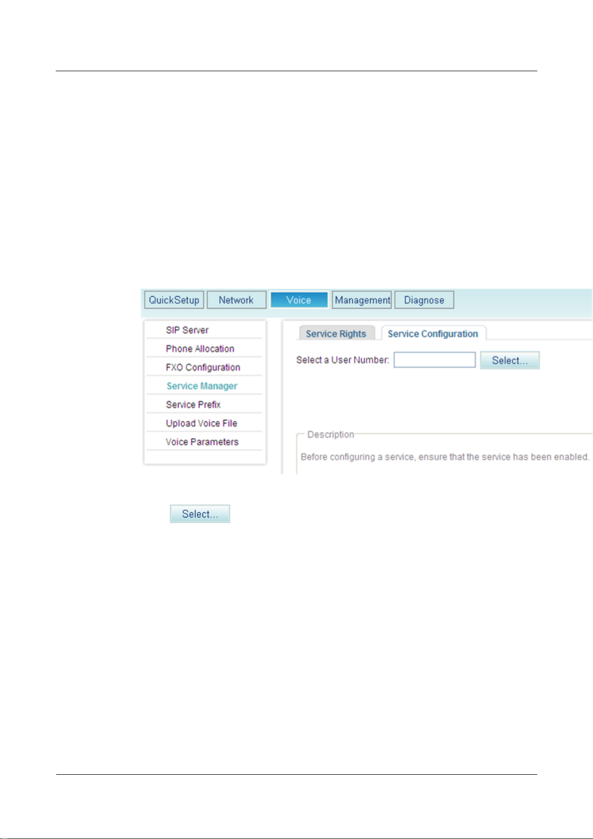
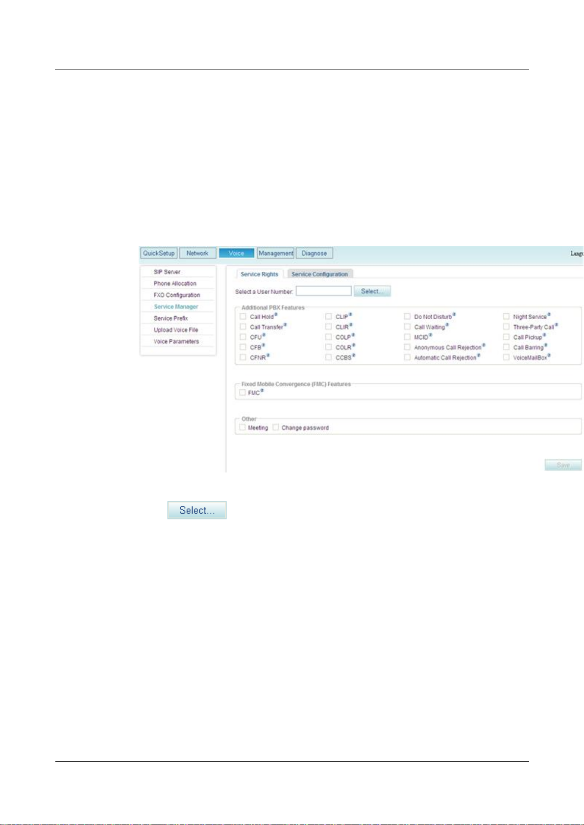
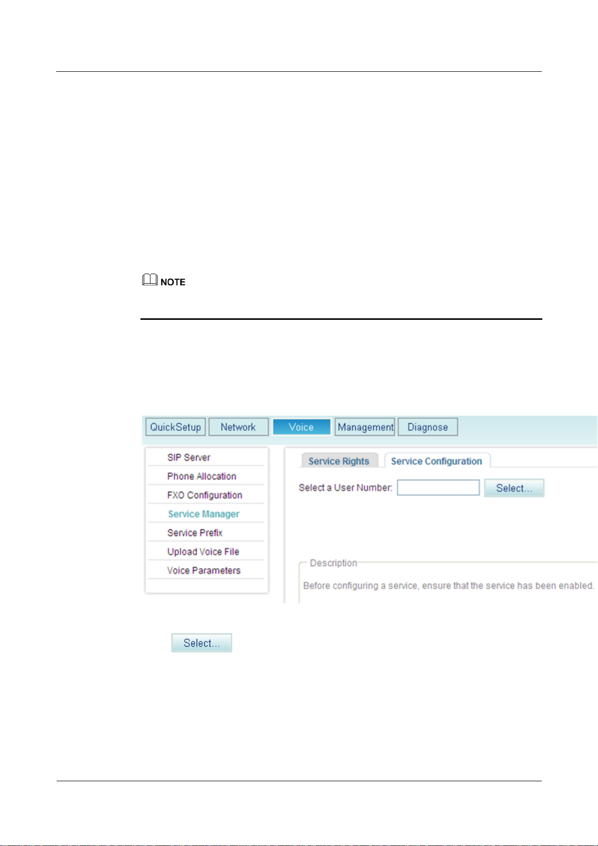
Step 1 On the web management system, choose Voice > Service Manager from the navigation tree.
Step 2 Click the Service Configuration tab.
The page shown in Figure 7-118 is displayed.
Figure 7-118 Configure Service tab page (1)
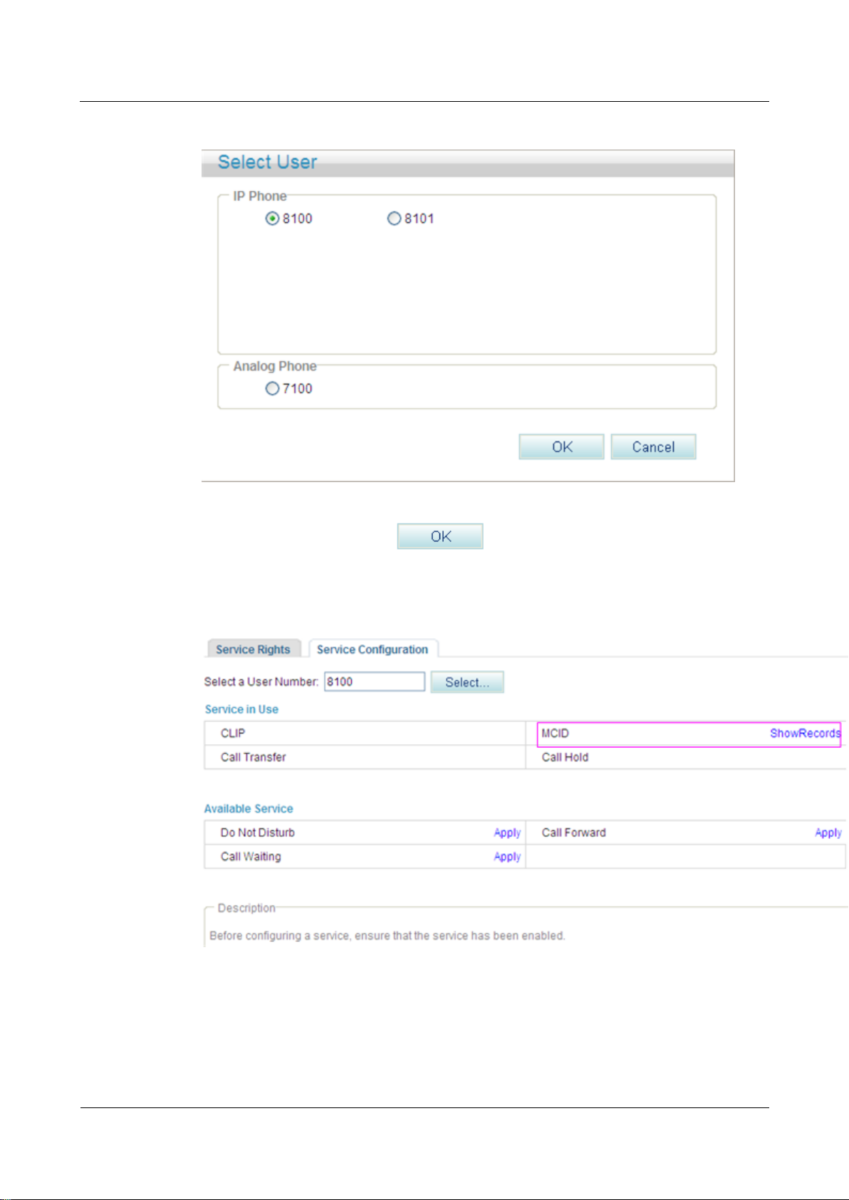
Step 3 Click .
The page shown in Figure 7-119 is displayed.
eSpace EGW1520 Enterprise Gateway
Product Documentation
7 Feature Description and Implementation
Issue 01 (2012-05-15)
Huawei Proprietary and Confidential
Copyright © Huawei Technologies Co., Ltd.
200
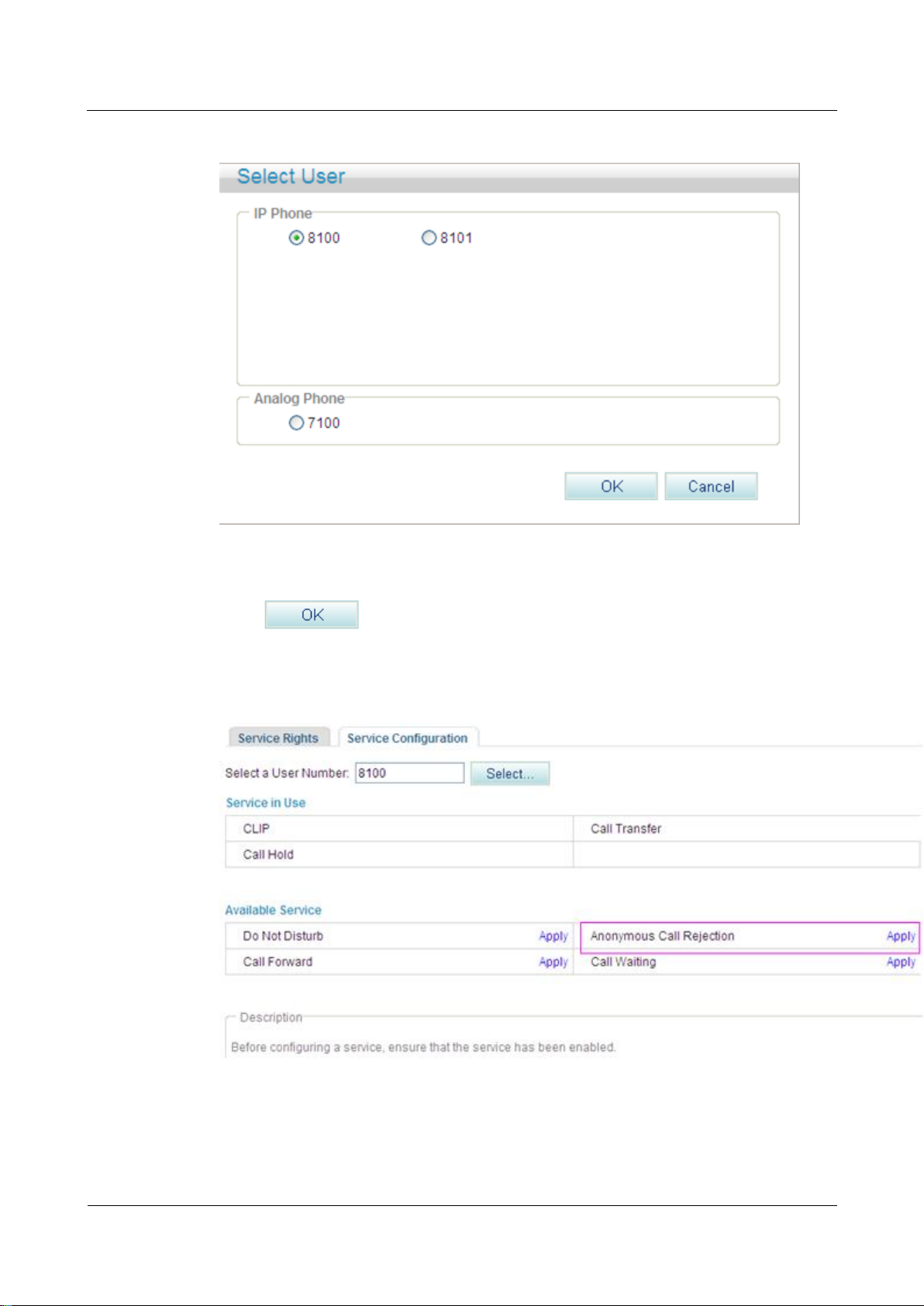
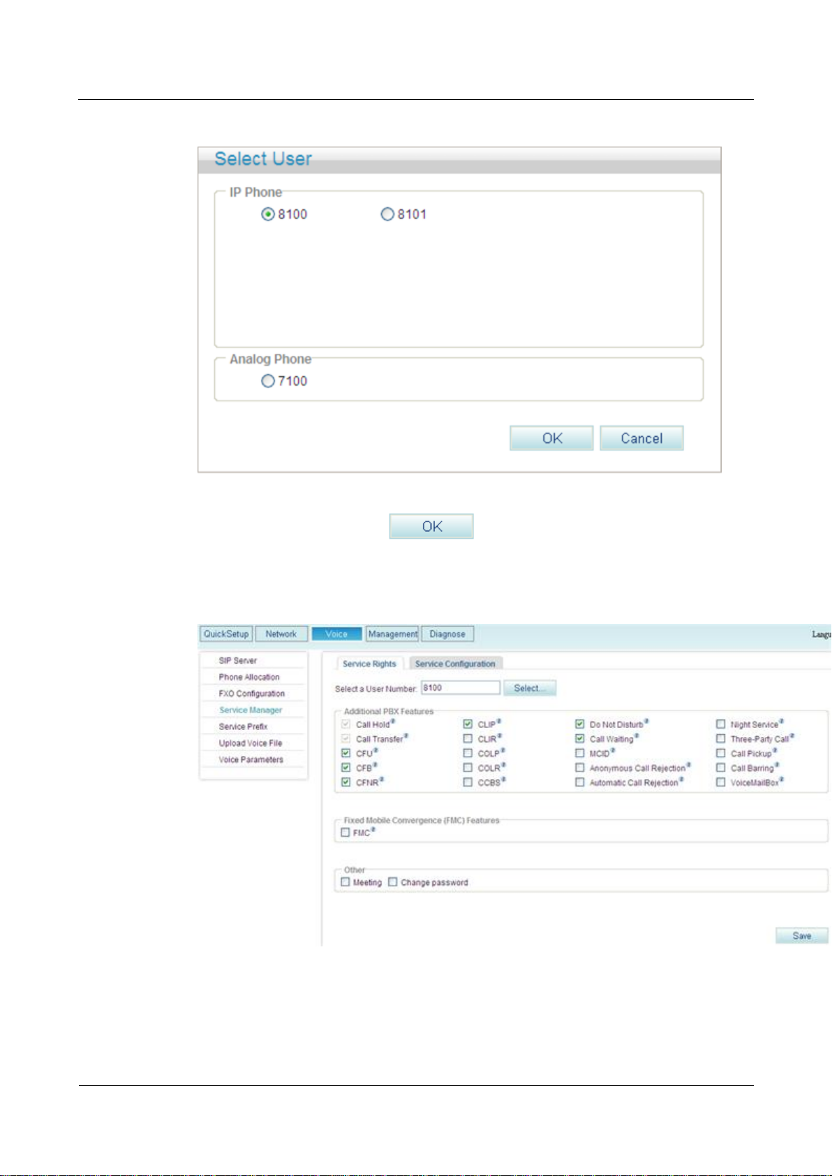
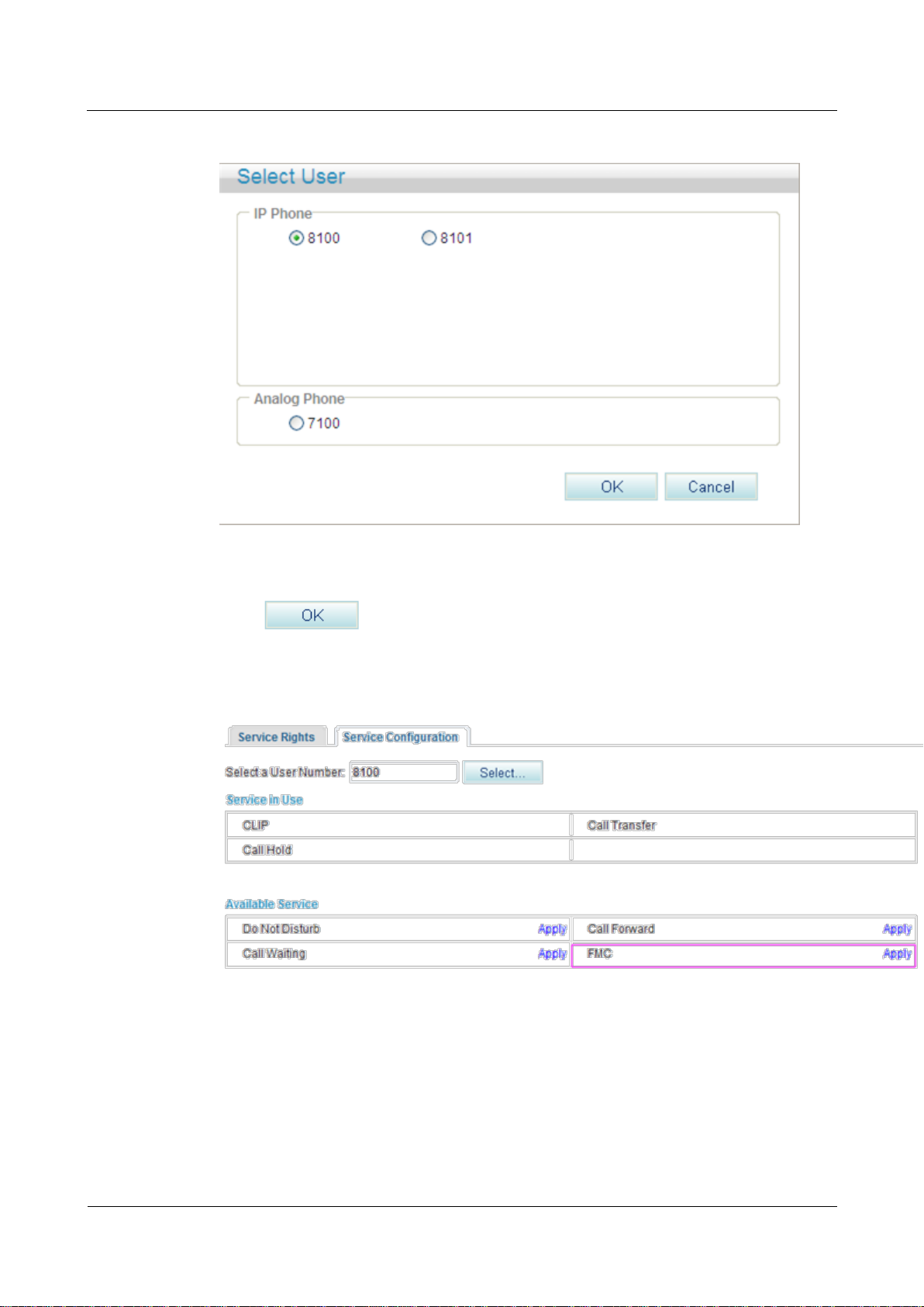
Figure 7-119 Selecting a user
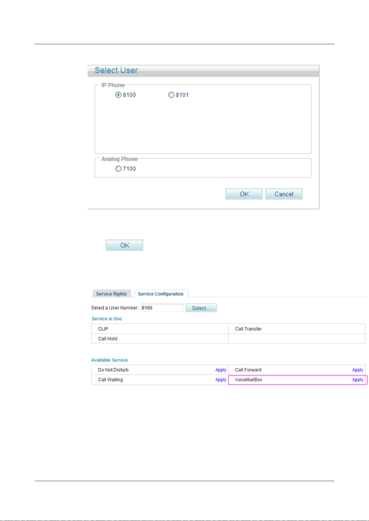
Step 4 Select a user number, and click .
The page shown in Figure 7-120 is displayed.
Figure 7-120 Configure Service tab page (2)
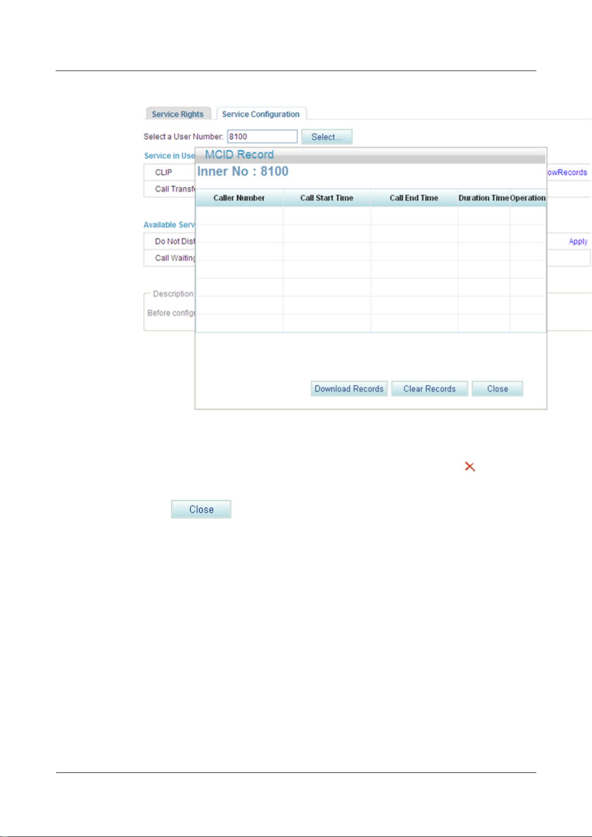
Step 5 Click ShowRecords.
The page shown in Figure 7-121 is displayed.
You can view, download, or delete all malicious call records.
eSpace EGW1520 Enterprise Gateway
Product Documentation
7 Feature Description and Implementation
Issue 01 (2012-05-15)
Huawei Proprietary and Confidential
Copyright © Huawei Technologies Co., Ltd.
201
Figure 7-121 Configure Service tab page (3)
Step 6 (Optional) Click Download Records, and download malicious call records as prompted.
Step 7 (Optional) Click Clear Records to clear call malicious call records, or click to delete a
single record.
Step 8 Click to close the page.
----End
?.15.Anonymous Call Rejection
After a user enables the anonymous call rejection service, the EGW1520 will block all
anonymous calls to the user.
Precautions
The anonymous call rejection service conflicts with some other services. For details, see
Service Conflicts.
Configuring the Service
Web mode
eSpace EGW1520 Enterprise Gateway
Product Documentation
7 Feature Description and Implementation
Issue 01 (2012-05-15)
Huawei Proprietary and Confidential
Copyright © Huawei Technologies Co., Ltd.
202
Before configuring a service, ensure that the service has been enabled. For details on how to
enable voice services, see Enabling Voice Services.
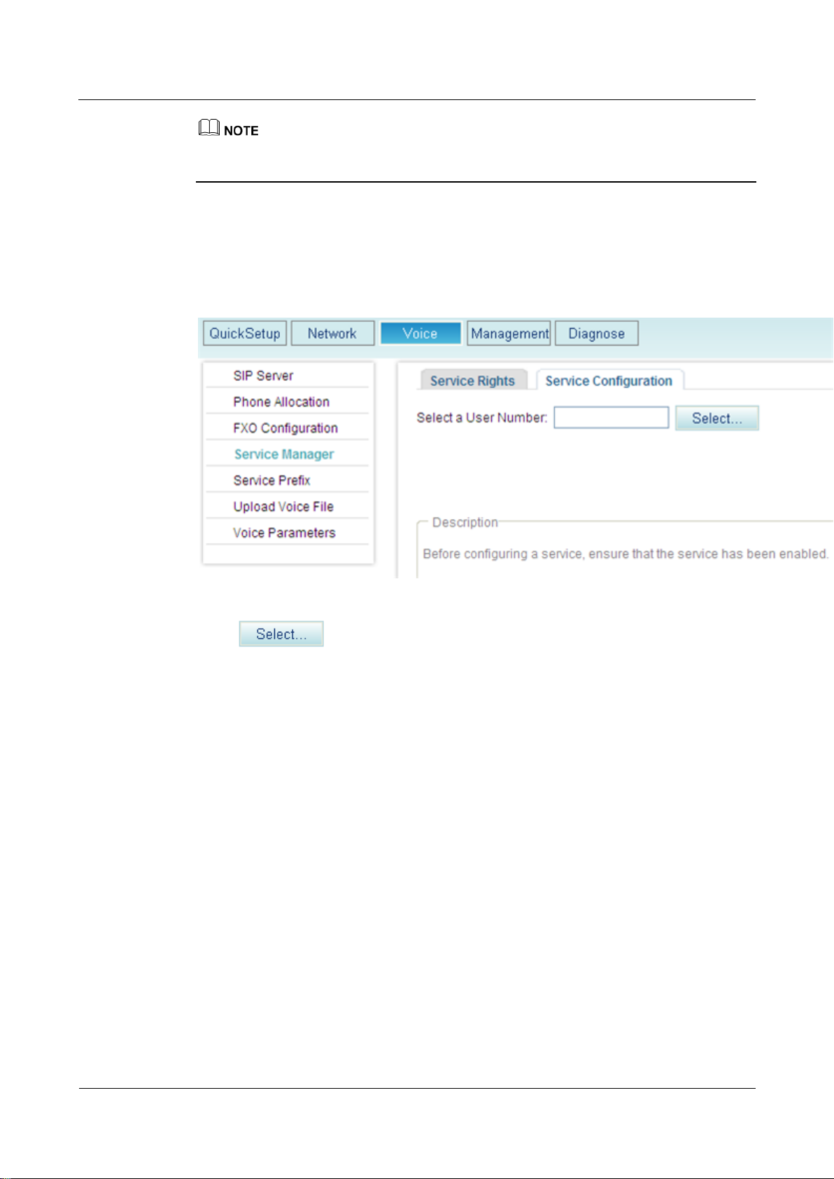
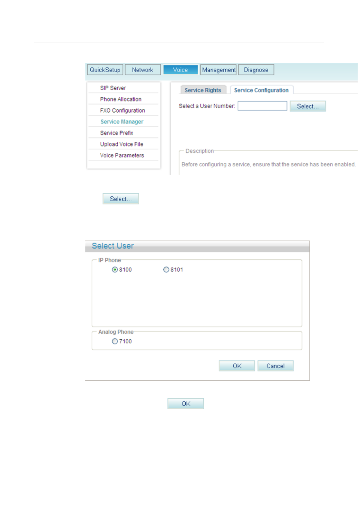
Step 1 On the web management system, choose Voice > Service Manager from the navigation tree.
Step 2 Click the Service Configuration tab.
The page shown in Figure 7-122 is displayed.
Figure 7-122 Configure Service tab page (1)
Step 3 Click .
The page shown in Figure 7-123 is displayed.
eSpace EGW1520 Enterprise Gateway
Product Documentation
7 Feature Description and Implementation
Issue 01 (2012-05-15)
Huawei Proprietary and Confidential
Copyright © Huawei Technologies Co., Ltd.
203
Figure 7-123 Selecting a user
Step 4 Select a user number.
Step 5 Click .
The page shown in Figure 7-124 is displayed.
Figure 7-124 Configure Service tab page (2)
Step 6 Click Apply.
Figure 7-125 shows the configuration result.
eSpace EGW1520 Enterprise Gateway
Product Documentation
7 Feature Description and Implementation
Issue 01 (2012-05-15)
Huawei Proprietary and Confidential
Copyright © Huawei Technologies Co., Ltd.
204
Figure 7-125 Configuration result
----End
Service prefix dialing mode
In addition to the preceding web mode, you can also dial a prefix to configure the service. For
example, pick up the phone and dial default service prefix *41#. To change the service prefix,
see Changing Service Prefixes.
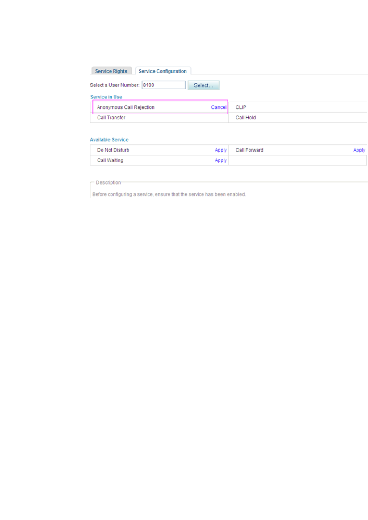
Using the Service
Assume that user A has enabled and configured the anonymous call rejection service and that
user B is an anonymous user (for example, user B enables the CLIR service). User B's calls to
user A will be blocked.
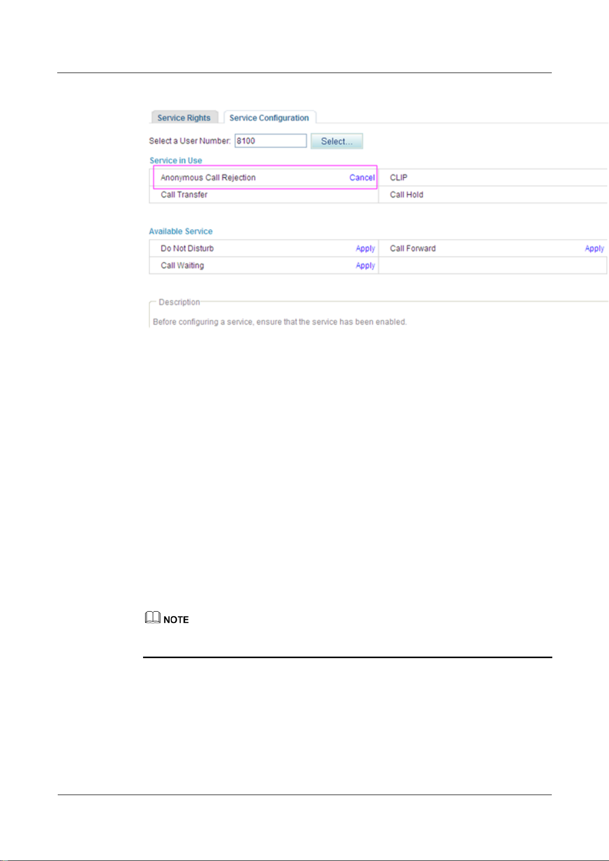
Canceling the Service
Web mode
Click Cancel on the Service Configuration tab page, as shown in Figure 7-126.
eSpace EGW1520 Enterprise Gateway
Product Documentation
7 Feature Description and Implementation
Issue 01 (2012-05-15)
Huawei Proprietary and Confidential
Copyright © Huawei Technologies Co., Ltd.
205
Figure 7-126 Canceling the service
Service prefix dialing mode
A user picks up the phone and dials default service prefix #41#. To change the service prefix,
see Changing Service Prefixes.
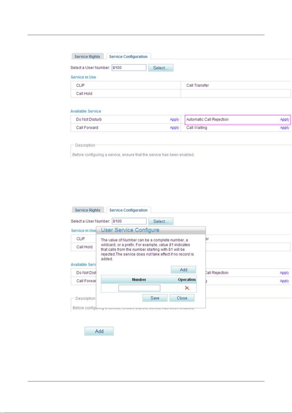
?.16.Automatic Call Rejection
After a user enables and configures the automatic call rejection service, the calls from a preset
number will be rejected automatically.
Precautions
The automatic call rejection service conflicts with some other services. For details, see
Service Conflicts.
Configuring the Service
Web mode
Before configuring a service, ensure that the service has been enabled. For details on how to
enable voice services, see Enabling Voice Services.
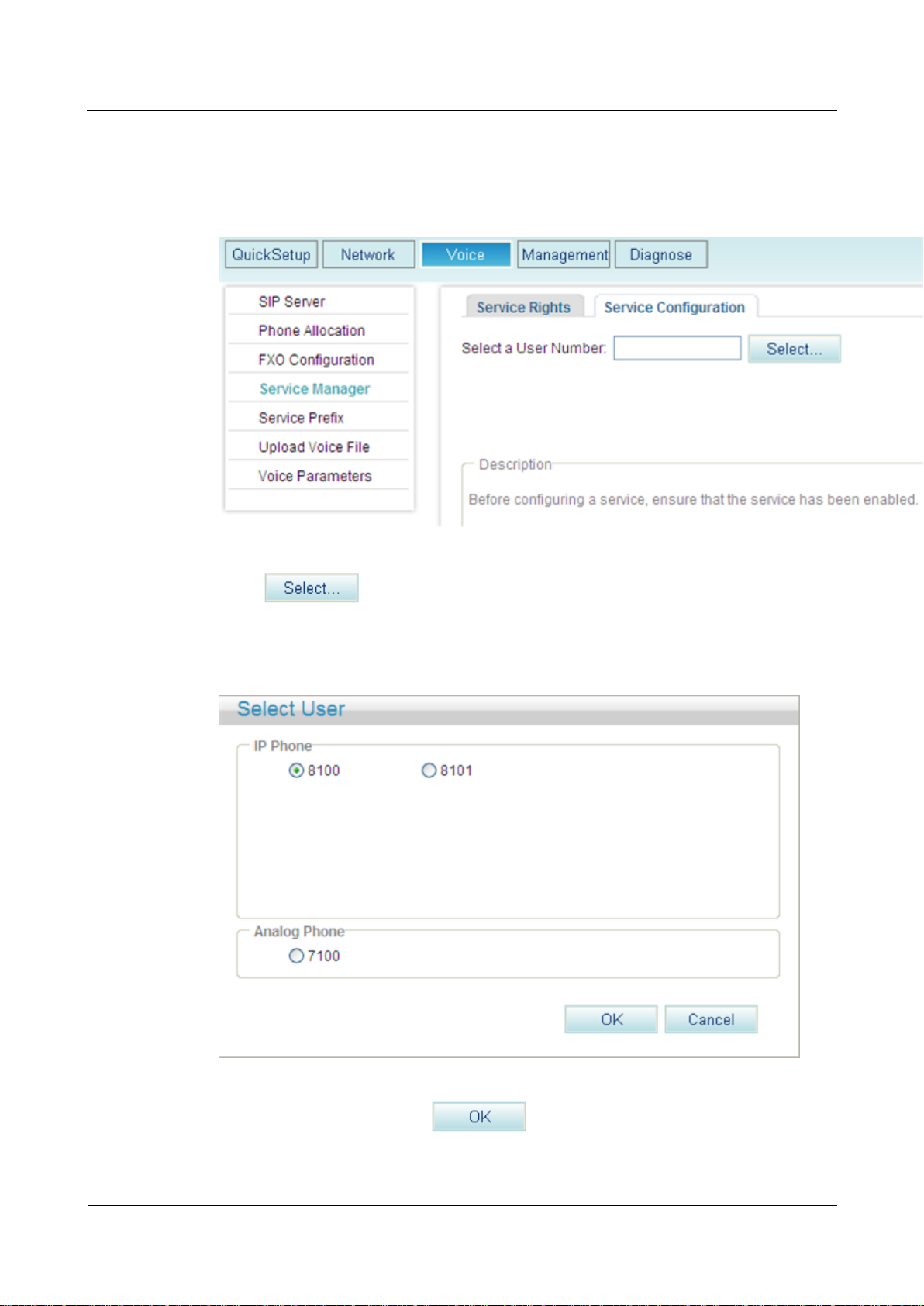
Step 1 On the web management system, choose Voice > Service Manager from the navigation tree.
Step 2 Click the Service Configuration tab.
The page shown in Figure 7-127 is displayed.
eSpace EGW1520 Enterprise Gateway
Product Documentation
7 Feature Description and Implementation
Issue 01 (2012-05-15)
Huawei Proprietary and Confidential
Copyright © Huawei Technologies Co., Ltd.
206
Figure 7-127 Configure Service tab page (1)
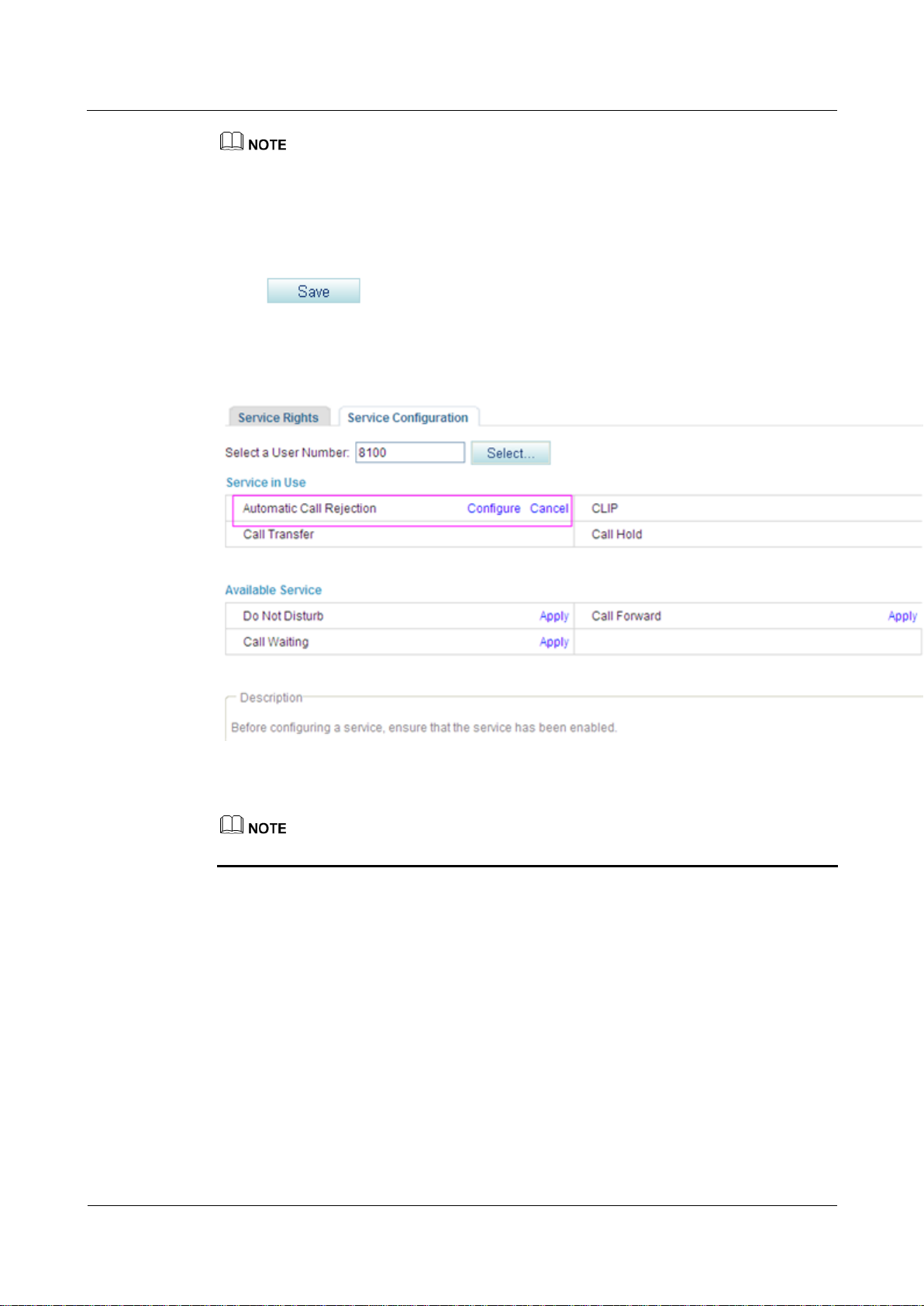
Step 3 Click .
The page shown in Figure 7-128 is displayed.
Figure 7-128 Selecting a user
Step 4 Select a user number, and click .
The page shown in Figure 7-129 is displayed.
eSpace EGW1520 Enterprise Gateway
Product Documentation
7 Feature Description and Implementation
Issue 01 (2012-05-15)
Huawei Proprietary and Confidential
Copyright © Huawei Technologies Co., Ltd.
207
Figure 7-129 Configure Service tab page (2)
Step 5 Click Apply.
The page shown in Figure 7-130 is displayed.
Figure 7-130 Configure Service tab page (3)
Step 6 Click , and enter a number that you want to reject.
eSpace EGW1520 Enterprise Gateway
Product Documentation
7 Feature Description and Implementation
Issue 01 (2012-05-15)
Huawei Proprietary and Confidential
Copyright © Huawei Technologies Co., Ltd.
208
You can enter a complete number or the first several digits of a number in the Number text box. For
example, if you enter 8100, the number 8100 and numbers that start with 8100 are rejected.
A maximum of 10 numbers can be added. The length of each number must be equal to or less than
30 characters.
When no rejected number is configured, the system saves the settings of the Automatic Call
Rejection (ACR) service but does not reject the calls from any numbers.
Step 7 Click .
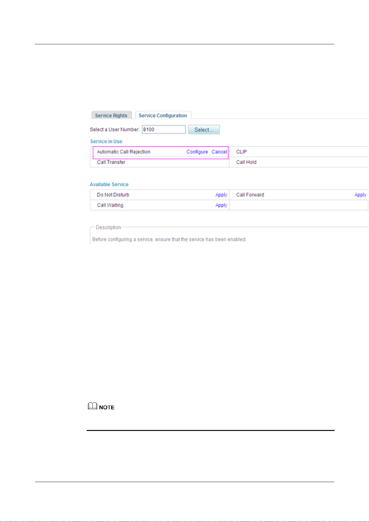
Figure 7-131 shows the configuration result.
Figure 7-131 Configuration result
To modify the configuration, click Configure.
----End
Service prefix dialing mode
In addition to the preceding web mode, you can also dial a prefix to configure the service.
For example, pick up the phone and dial *97*number1*number2*number3#, where number1,
number2, and number3 indicate numbers that you want to reject and *97* is the default
service prefix. The length of each number must be equal to or less than 27 characters. To
change the service prefix, see Viewing and Changing Service Prefixes.
Using the Service
Assume that user A has enabled and configured the automatic call rejection service and user
B's number is rejected. User A's phone will automatically reject calls made by user B.
eSpace EGW1520 Enterprise Gateway
Product Documentation
7 Feature Description and Implementation
Issue 01 (2012-05-15)
Huawei Proprietary and Confidential
Copyright © Huawei Technologies Co., Ltd.
209
Canceling the Service
Web mode
Click Cancel on the Service Configuration tab page, as shown in Figure 7-132.
Figure 7-132 Canceling the service
Service prefix dialing mode
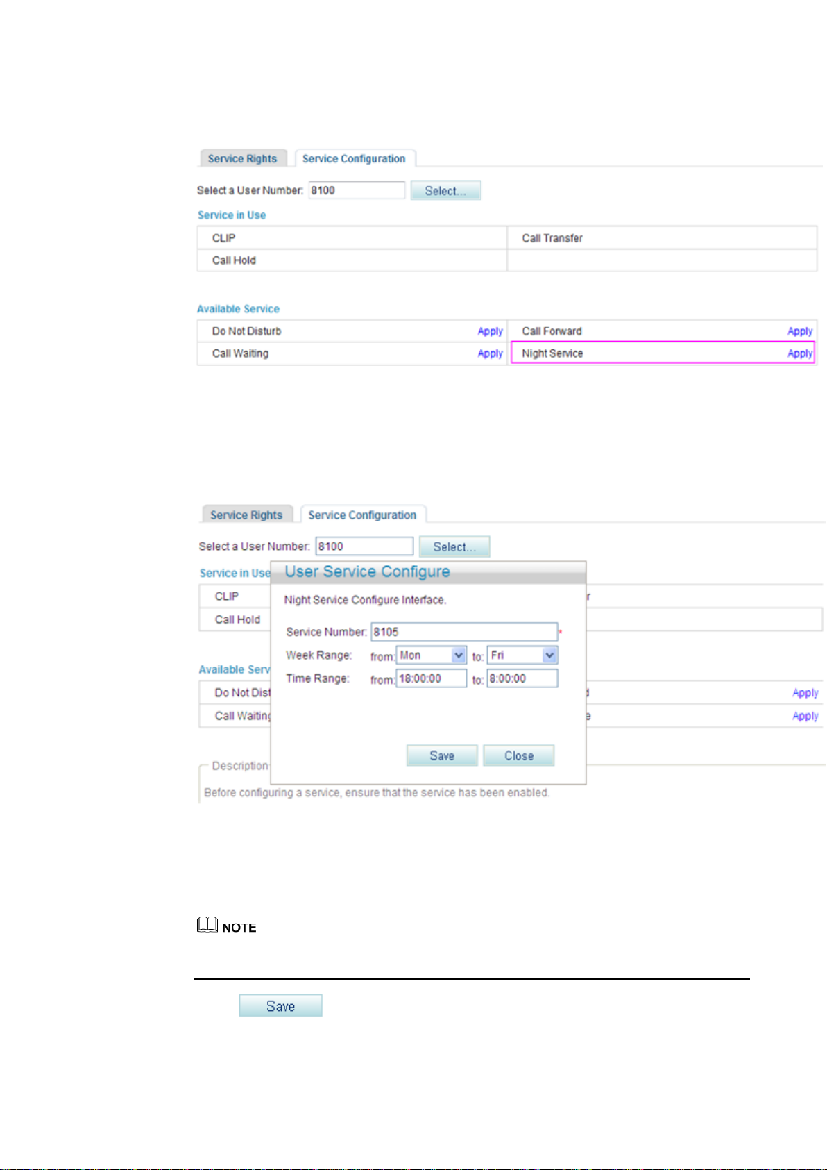
?.17.Night Service
If a user configures the night service, all incoming calls at night are forwarded to the voice
mailbox or a preset number.
Precautions
The night service conflicts with some other services. For details, see Service Conflicts.
Before configuring a service, ensure that the service has been enabled. For details on how to
enable voice services, see Enabling Voice Services.
A user picks up the phone and dials #97# to cancel the rejection of all preset numbers.
A user picks up the phone and dials #97*number1*number2*number3#, where number1,
number2, and number3 indicate numbers that the user does not want to reject any longer
and #97* is the default service prefix. To change the service prefix, see Changing
Service Prefixes.
Configuring the Service
Step 1 On the web management system, choose Voice > Service Manager from the navigation tree.
eSpace EGW1520 Enterprise Gateway
Product Documentation
7 Feature Description and Implementation
Issue 01 (2012-05-15)
Huawei Proprietary and Confidential
Copyright © Huawei Technologies Co., Ltd.
210
Step 2 Click the Service Configuration tab.
The page shown in Figure 7-133 is displayed.
Figure 7-133 Configure Service tab page (1)
Step 3 Click .
The page shown in Figure 7-134 is displayed.
Figure 7-134 Selecting a user
Step 4 Select a user number, and click .
The page shown in Figure 7-135 is displayed.
eSpace EGW1520 Enterprise Gateway
Product Documentation
7 Feature Description and Implementation
Issue 01 (2012-05-15)
Huawei Proprietary and Confidential
Copyright © Huawei Technologies Co., Ltd.
211
Figure 7-135 Configure Service tab page (2)
Step 5 Click Apply.
The page shown in Figure 7-136 is displayed.
Figure 7-136 Configure Service tab page (3)
Step 6 Enter the forwarded-to number or voice mailbox prefix in the Service Number text box, and
set Week Range and Time Range.
The default voice mailbox prefix is 9898 (inner mailbox) or 9899 (network mailbox). To
change the voice mailbox prefix, see Viewing and Changing Service Prefixes.
Step 7 Click .
eSpace EGW1520 Enterprise Gateway
Product Documentation
7 Feature Description and Implementation
Issue 01 (2012-05-15)
Huawei Proprietary and Confidential
Copyright © Huawei Technologies Co., Ltd.
212
Figure 7-137 shows the configuration result.
Figure 7-137 Configuration result
To modify service configurations, click Configure corresponding to the service.
----End
Using the Service
Assume that user A has enabled and configured the night service. User A's incoming calls at
night are forwarded to the voice mailbox or a preset number.
Canceling the Service
Click Cancel on the Service Configuration tab page, as shown in Figure 7-138.
Figure 7-138 Canceling the service

eSpace EGW1520 Enterprise Gateway
Product Documentation
7 Feature Description and Implementation
Issue 01 (2012-05-15)
Huawei Proprietary and Confidential
Copyright © Huawei Technologies Co., Ltd.
213
?.18.Three-Party Calling
A user in a call can invite a third party to start a three-party conversation. An EGW1520
supports a maximum of two concurrent three-party calls.
Configuring the Service
After enabling the three-party call service, users can directly use it without configuration. For
details on how to enable voice services, see Enabling Voice Services.
POTS users on the EGW1520 cannot initiate three-party calls.
If a SIP user initiates a three-party call, the audio mixing is performed on the IP phone.
Using the Service
Assume that user A who is talking with user B has the three-party call service right. The
process of using the service varies according to the phone that user A uses.
1. Press an idle line key (the indicator is off), dial user C's number, and press the Send key.
2. If user C is connected (the corresponding indicator is on), press the CONF key and the
related line key (connecting users A and C) to start a three-party call.
If user C is not connected, press the related line key (connecting users A and B) to
continue the talk with user B.
If user B (user C) hangs up the phone during the three-party call, user A talks with user C (user B). If
user A hangs up the phone during the three-party call, users B and C listen to a busy tone.
Operations vary according to IP phone model. For details, see the related IP phone user guide.
?.19.Call Pickup
After dialing the call pickup access code and the called user's number, a user can answer the
call for the called user whose phone is ringing.
Configuring the Service
After enabling the call pickup service, users can directly use it without configuration. For
details on how to enable voice services, see Enabling Voice Services.
Using the Service
Assume that user A has the call pickup service right.
Step 1 User C dials user B, and user B's phone rings.
Step 2 User A picks up the phone and dials *11*TN# (TN is user B's number). User B's phone stops
ringing, and user A talks with user C.
In the preceding number, *11* is the default access code. To change the service prefix, see
Changing Service Prefixes.
----End
eSpace EGW1520 Enterprise Gateway
Product Documentation
7 Feature Description and Implementation
Issue 01 (2012-05-15)
Huawei Proprietary and Confidential
Copyright © Huawei Technologies Co., Ltd.
214
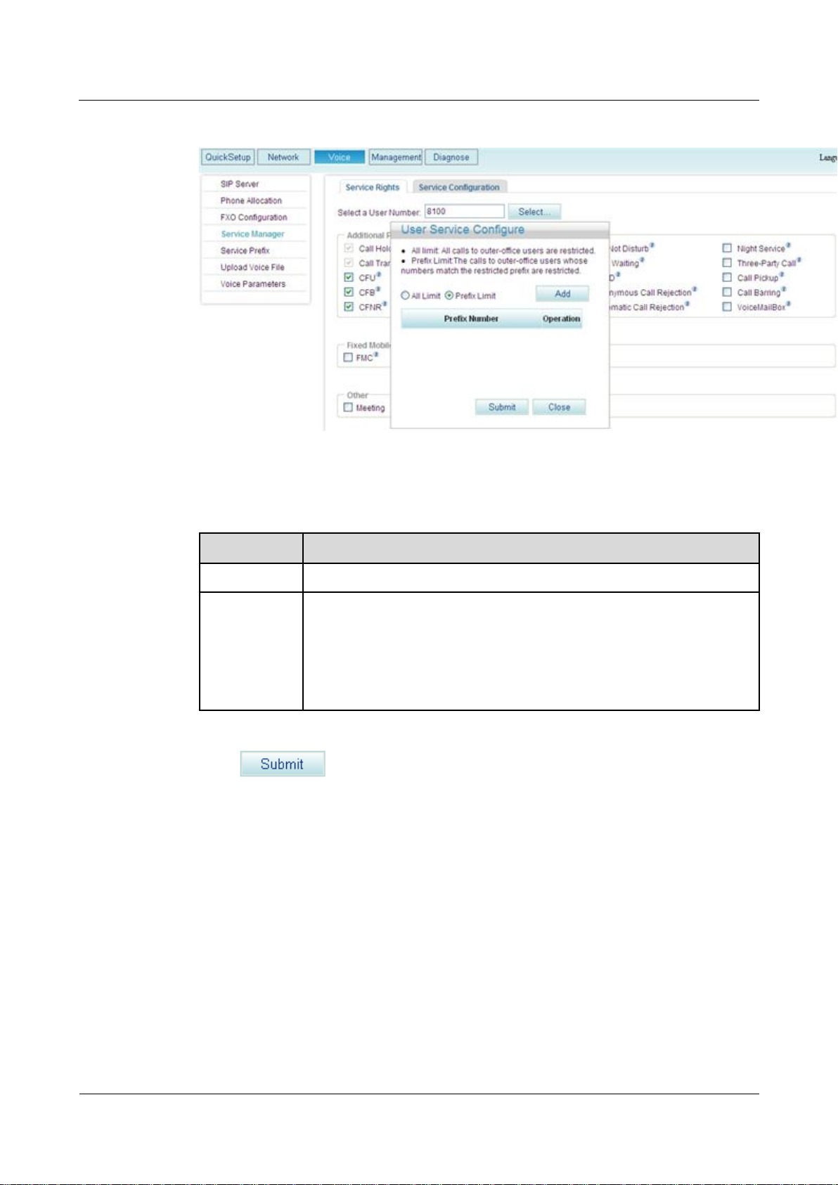
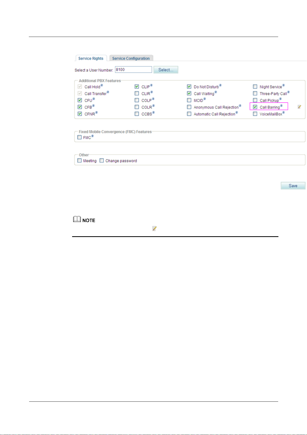
?.20.Call Barring
The call barring service limits calls to specified outer-office numbers. After the call barring
service is enabled, the calls whose numbers match the restricted prefix are not accessible to
the IMS or NGN.
Configuring the Service
Step 1 On the web management system, choose Voice > Service Manager from the navigation tree.
The page shown in Figure 7-139 is displayed.
Figure 7-139 Service Rights tab page (1)
Step 2 Click .
The page shown in Figure 7-140 is displayed.
eSpace EGW1520 Enterprise Gateway
Product Documentation
7 Feature Description and Implementation
Issue 01 (2012-05-15)
Huawei Proprietary and Confidential
Copyright © Huawei Technologies Co., Ltd.
215
Figure 7-140 Selecting a user
Step 3 Select a user number, and click .
The page shown in Figure 7-141 is displayed.
Figure 7-141 Service Rights tab page (2)
Step 4 Select Call Barring.
The page shown in Figure 7-142 is displayed.
eSpace EGW1520 Enterprise Gateway
Product Documentation
7 Feature Description and Implementation
Issue 01 (2012-05-15)
Huawei Proprietary and Confidential
Copyright © Huawei Technologies Co., Ltd.
216
Figure 7-142 Call barring
Parameter
Description
All Limit
Calls are blocked to all outer-office numbers.
Prefix Limit
Calls are blocked to certain outer-office prefixes. You can set one or more
service prefixes. If you add service prefix 81, calls made by internal users
to outer-office numbers starting 81 will be rejected.
NOTE
The call barring service limits calls to specified outer-office numbers. Calls to
intra-office numbers, however, are not limited.
Step 5 Set outer-office numbers to which calls are blocked according to Table 7-33.
Table 7-33 Parameter description
Step 6 Click .
Figure 7-143 shows the configuration result.
eSpace EGW1520 Enterprise Gateway
Product Documentation
7 Feature Description and Implementation
Issue 01 (2012-05-15)
Huawei Proprietary and Confidential
Copyright © Huawei Technologies Co., Ltd.
217
Figure 7-143 Configuration result
To modify the configuration, click .
----End
Using the Service
Assume that user A has configured the call barring service and that the restricted prefix is 88.
When user A calls outer-office user C on the IMS or NGN whose number starts with 88, the
call will fail.
Canceling the Service
To remove the call barring right, deselect Call Barring on the Service Rights tab page.
?.21.Voice Mailbox
After you configure the voice mailbox service, the voice mailbox can automatically answer
incoming calls and ask the calling users to leave voice messages. Then the phone displays a
message indicating that you have a voice message. The user can dial an access code to listen
to the voice message.
Precautions
The voice mailbox service conflicts with some other services. For details, see Service
Conflicts.
eSpace EGW1520 Enterprise Gateway
Product Documentation
7 Feature Description and Implementation
Issue 01 (2012-05-15)
Huawei Proprietary and Confidential
Copyright © Huawei Technologies Co., Ltd.
218
An EGW1520 allows a maximum of 24 users to enable the voice mailbox service.
The maximum duration of a voice message is 30 seconds.
An EGW1520 user can leave at least one voice message. All EGW1520 users can leave
120 voice messages. When the number of voice messages reaches 120, no more voice
messages are allowed. To leave new voice messages, you must delete old ones.
If the CFU service is configured for your voice mailbox, you do not need to configure
the call transfer to voice message on busy (CTVMB) service and call transfer to voice
mailbox on no reply (CTVMNR) service.
Configuring the Service
Web mode
Before configuring a service, ensure that the service has been enabled. For details on how to
enable voice services, see Enabling Voice Services.
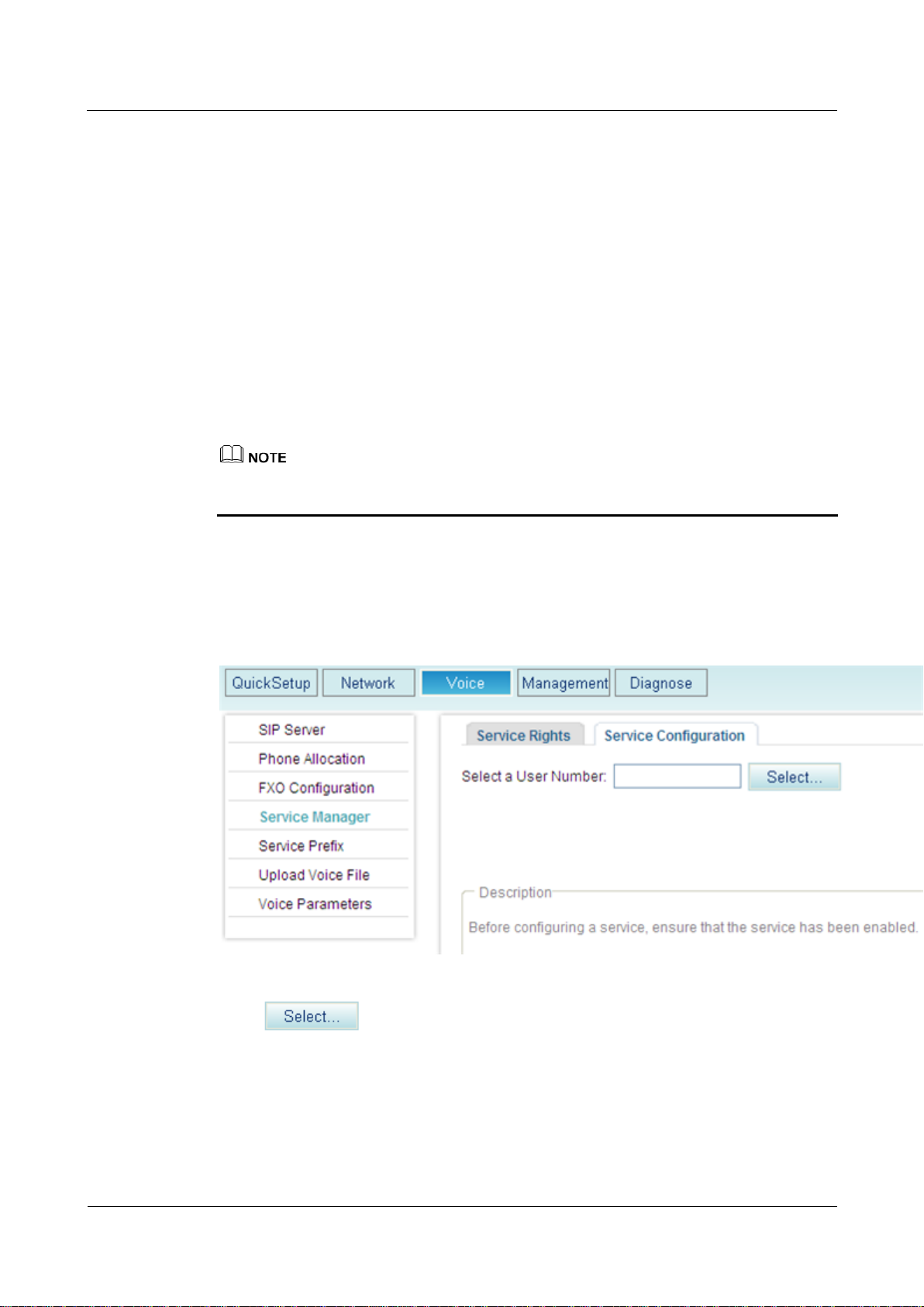
Step 1 On the web management system, choose Voice > Service Manager from the navigation tree.
Step 2 Click the Service Configuration tab.
The page shown in Figure 7-144 is displayed.
Figure 7-144 Configure Service tab page (1)
Step 3 Click .
The page shown in Figure 7-145 is displayed.
eSpace EGW1520 Enterprise Gateway
Product Documentation
7 Feature Description and Implementation
Issue 01 (2012-05-15)
Huawei Proprietary and Confidential
Copyright © Huawei Technologies Co., Ltd.
219
Figure 7-145 Selecting a user
Step 4 Select a user number.
Step 5 Click .
The page shown in Figure 7-146 is displayed.
Figure 7-146 Configure Service tab page (2)
Step 6 Click Apply.
The page shown in Figure 7-147 is displayed.
eSpace EGW1520 Enterprise Gateway
Product Documentation
7 Feature Description and Implementation
Issue 01 (2012-05-15)
Huawei Proprietary and Confidential
Copyright © Huawei Technologies Co., Ltd.
220
Figure 7-147 Configure Service tab page (3)
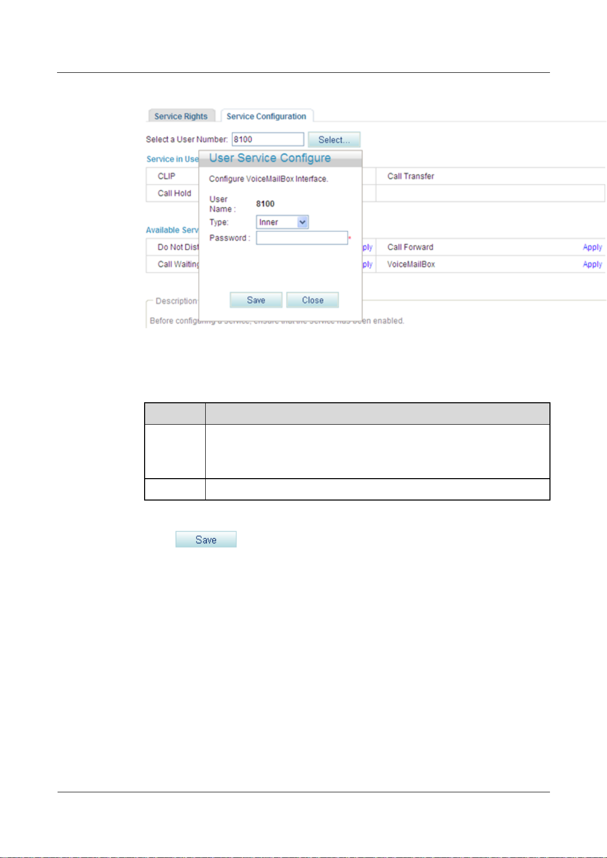
Parameter
Description
Type
Mailbox type.
Inner: voice mailbox on the EGW1520
Network: voice mailbox of a carrier
Password
Password for a user to retrieve messages, consisting of 4 to 8 digits.
Step 7 Set parameters according to Table 7-34.
Table 7-34 Parameter description
Step 8 Click .
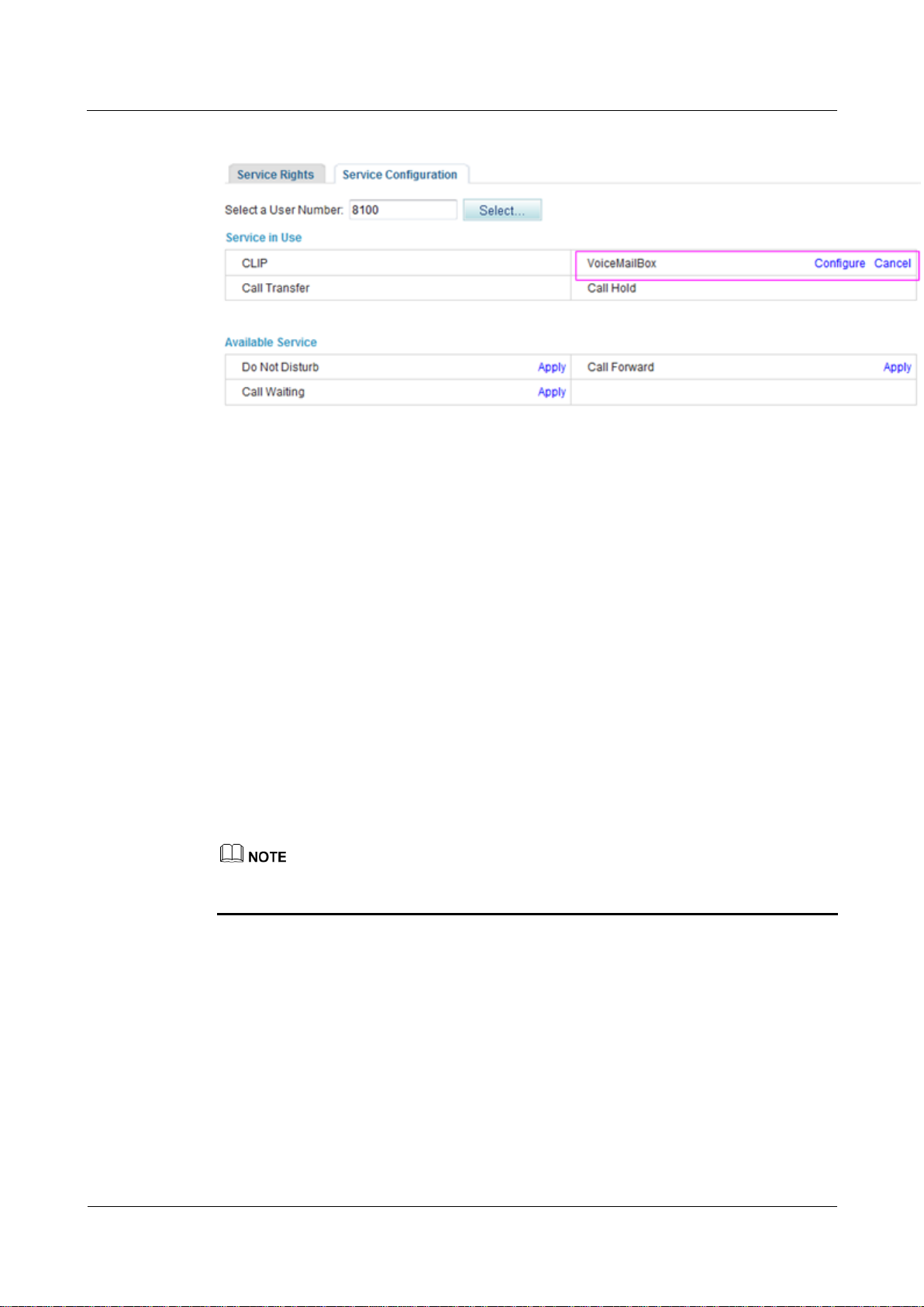
Figure 7-148 shows the configuration result.
eSpace EGW1520 Enterprise Gateway
Product Documentation
7 Feature Description and Implementation
Issue 01 (2012-05-15)
Huawei Proprietary and Confidential
Copyright © Huawei Technologies Co., Ltd.
221
Figure 7-148 Configuration result
Step 9 When configuring the call forwarding or night service, you can set the forwarded-to number
to the voice mailbox prefix. The default voice mailbox prefix is 9898 (inner mailbox) or 9899
(network mailbox). To change the voice mailbox prefix, see Viewing and Changing Service
Prefixes.
For details on how to configure call forwarding services, see Call Forwarding on Busy,
Call Forwarding on No Reply, and Call Forwarding Unconditional.
For details on how to configure the night service, see Night Service.
----End
Service prefix dialing mode
A user picks up the phone and configures a forwarding service. The forwarded-to number is a
voice mailbox prefix 9898 or 9899. To change the service prefix, see Changing Service
Prefixes.
To configure forwarding services, see Call Forwarding on Busy, Call Forwarding on No Reply,
and Call Forwarding Unconditional.
When you set the forwarded-to number to a voice mailbox prefix in the night service, you can
only use the web mode.
Using the Service
Assume that user A has enabled and configured the voice mailbox service. If user B is an
outer-office user, the process of using the voice mailbox service is as follows:
1. User B calls user A. After listening to the message-taking voice prompt, user B takes a
2. User B listens to an announcement saying that the voice message is taken successfully,
3. User A finds that the phone received a new voice message and dials access code 91001
voice message and then presses the pound key (#).
and then hangs up. User B can also play the recorded voice message, take a voice
message again, and cancel the voice message.
to retrieve it from the EGW1520 voice mailbox or 91002 from the carrier's voice
eSpace EGW1520 Enterprise Gateway
Product Documentation
7 Feature Description and Implementation
Issue 01 (2012-05-15)
Huawei Proprietary and Confidential
Copyright © Huawei Technologies Co., Ltd.
222
mailbox. User A enters the retrieving ID (user number) and password as prompted, and
presses the pound key (#). Then user A can listen to the voice message and perform other
settings, such as changing the password, as prompted.
The default access codes for retrieving messages are 91001 and 91002. To change the access
code, see Viewing and Changing Service Prefixes.
4. After the voice message is played, user A can delete it as prompted.
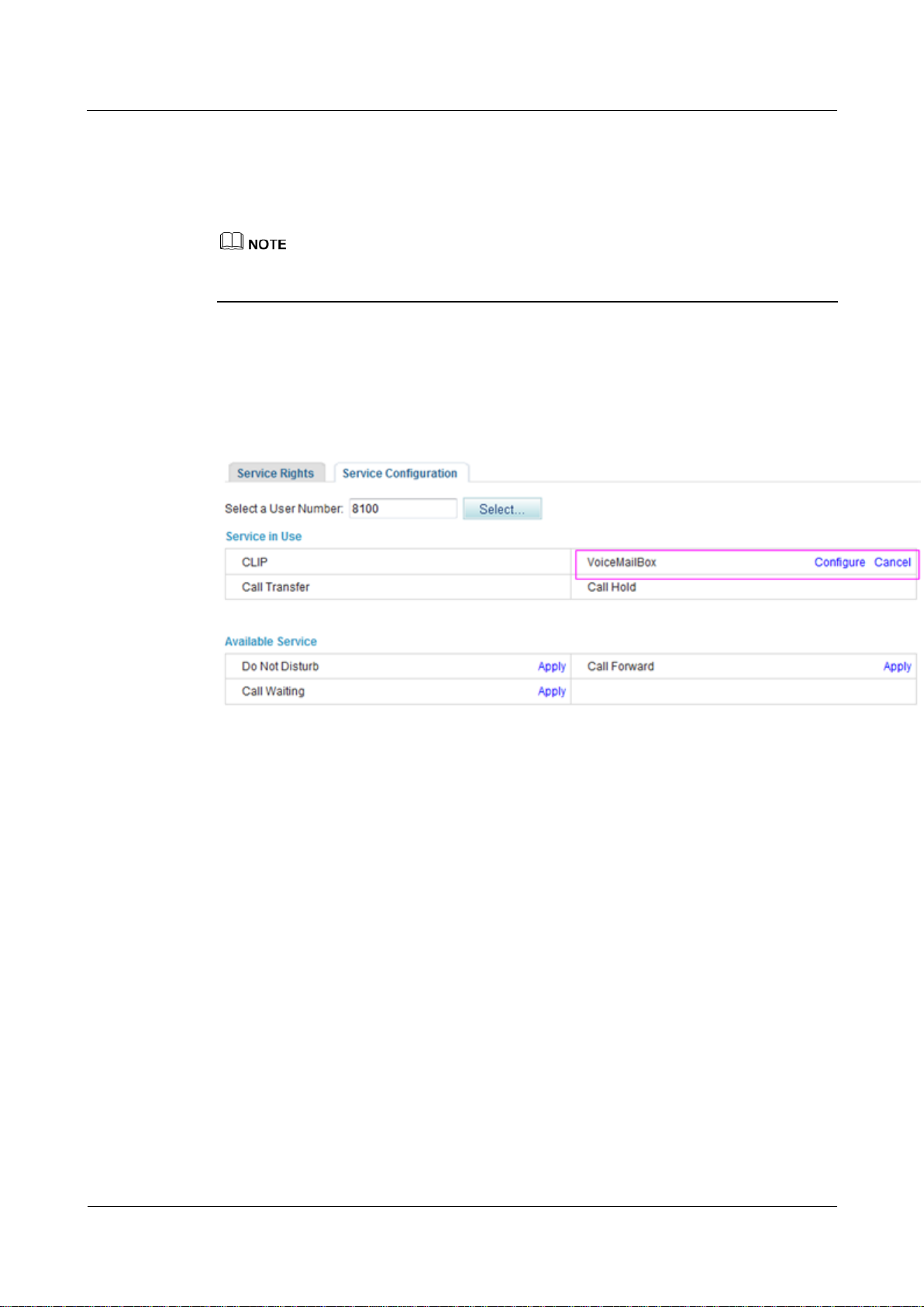
Canceling the Service
Click Cancel on the Service Configuration tab page, as shown in Figure 7-149.
Figure 7-149 Canceling the service
?.22.Fixed Mobile Convergence
The Fixed Mobile Convergence (FMC) service allows users to configure the simultaneous
ringing, sequential ringing, call toggling, and voice mailbox services.
Introduction
Simultaneous ringing
Configure a mobile number as the simultaneous ringing number of a fixed-line phone.
When a user receives a call, the mobile phone and the fixed-line phone ring together. The
user can pick up either of the phones to answer the call.
A user can be only configured with one simultaneous ringing number.
Sequential ringing
Configure a mobile number as the sequential ringing number of a fixed-line phone.
When a user receives a call, the fixed-line phone rings. If the user does not pick up the
fixed-line phone for a specified period, the mobile phone rings.
A user can be only configured with one sequential ringing number.
Call toggling
eSpace EGW1520 Enterprise Gateway
Product Documentation
7 Feature Description and Implementation
Issue 01 (2012-05-15)
Huawei Proprietary and Confidential
Copyright © Huawei Technologies Co., Ltd.
223
Configure a mobile number as the toggling number of a fixed-line phone. When a user is
in a call, the user can release the call after toggling it to the mobile phone.
Voice mailbox
After you configure the voice mailbox service, the voice mailbox can automatically
answer incoming calls and ask the calling users to leave voice messages. Then the phone
displays a message indicating that you have a voice message. To listen to the voice
message, dial an access code.
Precautions
The FMC service conflicts with some other services. For details, see Service Conflicts.
Configuring the Service
Before configuring a service, ensure that the service has been enabled. For details on how to
enable voice services, see Enabling Voice Services.
Step 1 On the web management system, choose Voice > Service Manager from the navigation tree.
Step 2 Click the Service Configuration tab.
The page shown in Figure 7-150 is displayed.
Figure 7-150 Configure Service tab page (1)
Step 3 Click .
The page shown in Figure 7-151 is displayed.
eSpace EGW1520 Enterprise Gateway
Product Documentation
7 Feature Description and Implementation
Issue 01 (2012-05-15)
Huawei Proprietary and Confidential
Copyright © Huawei Technologies Co., Ltd.
224
Figure 7-151 Selecting a user
Step 4 Select a user number.
Step 5 Click .
The page shown in Figure 7-152 is displayed.
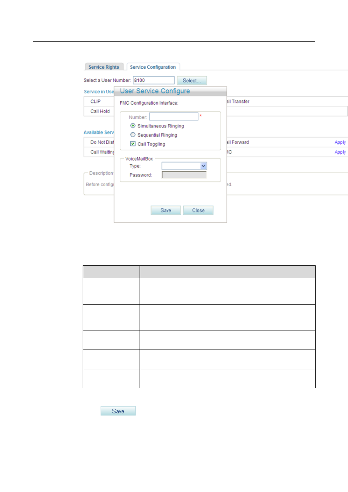
Figure 7-152 Configure Service tab page (2)
Step 6 Click Apply.
eSpace EGW1520 Enterprise Gateway
Product Documentation
7 Feature Description and Implementation
Issue 01 (2012-05-15)
Huawei Proprietary and Confidential
Copyright © Huawei Technologies Co., Ltd.
225
Figure 7-153 Configure Service tab page (3)
Parameter
Description
Mobile Number
Indicates the mobile number that you associate with the fixed-line
number in the simultaneous ringing, sequential ringing, and call
toggling services.
Simultaneous
Ringing
When a user receives a call, the mobile phone and the fixed-line
phone ring together. The user can pick up either of the phones to
answer the call.
Sequential Ringing
If a user does not answer an incoming call for a specified period, the
fixed-line phone stops ringing and the mobile phone starts ringing.
Call Toggling
A user can press the hook flash button and dial an access code to
switch the call to the mobile phone.
VoiceMailBox
Allows you to set the voice mailbox information. For details, see
Voice Mailbox.
Step 7 Set parameters according to Table 7-35.
Table 7-35 Parameter description
Step 8 Click .
Figure 7-154 shows the configuration result.
eSpace EGW1520 Enterprise Gateway
Product Documentation
7 Feature Description and Implementation
Issue 01 (2012-05-15)
Huawei Proprietary and Confidential
Copyright © Huawei Technologies Co., Ltd.
226
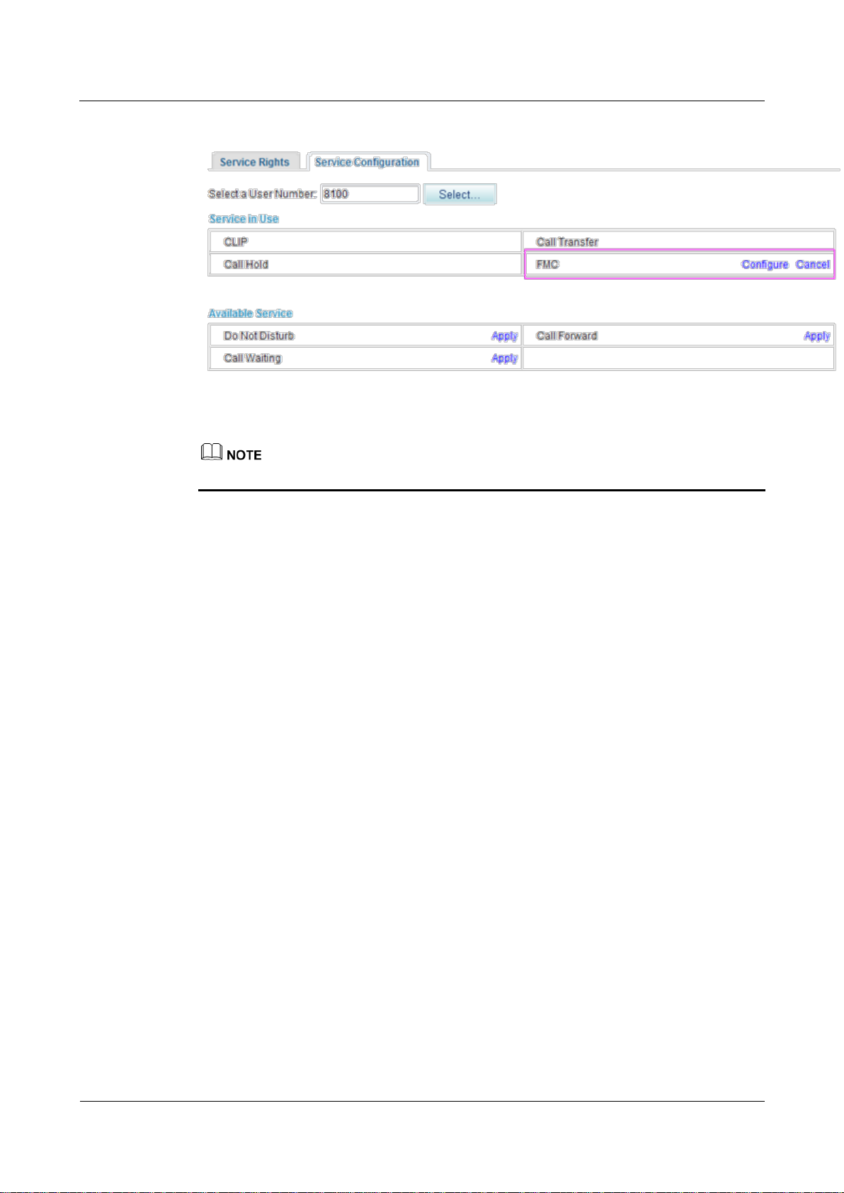
Figure 7-154 Configuration result
To modify the configuration, click Configure.
----End
Using the Service
Simultaneous ringing
Assume that user A has configured the simultaneous ringing service and user B's mobile
number is the simultaneous ringing number. When user C calls user A, user A's and user B's
phones ring at the same time. Both user A's and user B's phone can answer the call. When a
phone is picked up, the other phone stops ringing.
Sequential ringing
Assume that user A has configured the sequential ringing service and user B's mobile number
is the sequential ringing number. When user C calls user A but user A does not answer within
20 seconds, user A's phone stops ringing and user B's phone starts to ring. User B can answer
the call from user C.
Call toggling
Assume that user A has configured the call toggling service and that user B is the one to
whom the call is toggled. User A can exit the conversation with user C and enable user B to
talk with user C. The process is as follows:
1. User A presses the hook flash button and dials default service prefix *19# after hearing a
2. User B's phone rings. User B picks up the phone to talk with user C and user A releases
dialing tone. To change the service prefix, see Changing Service Prefixes.
the call.
Voicemail
For details on how to configure and use the voicemail service, see Voice Mailbox.
eSpace EGW1520 Enterprise Gateway
Product Documentation
7 Feature Description and Implementation
Issue 01 (2012-05-15)
Huawei Proprietary and Confidential
Copyright © Huawei Technologies Co., Ltd.
227
Canceling the Service
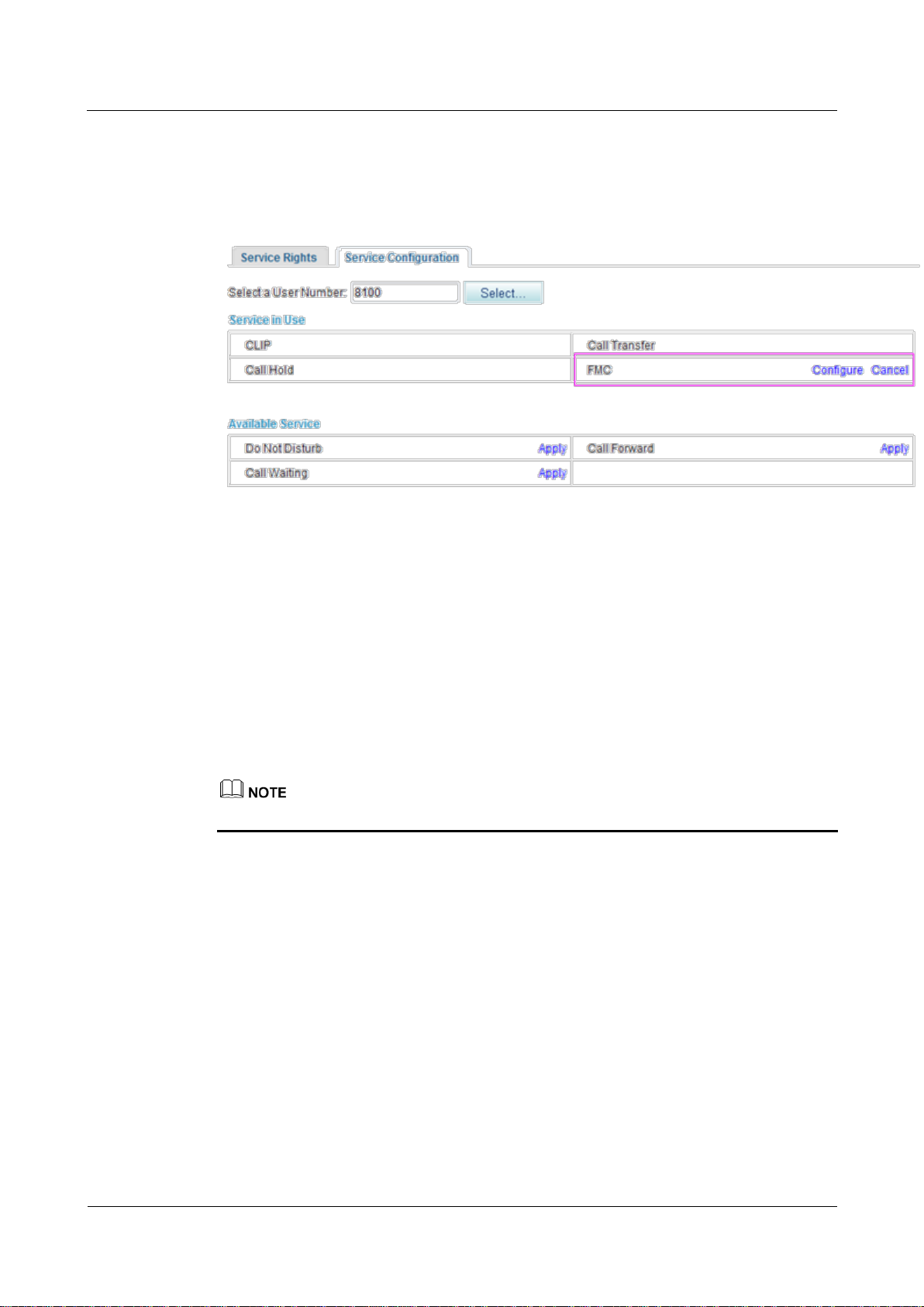
Click Cancel on the Service Configuration tab page, as shown in Figure 7-155.
Figure 7-155 Canceling the service
?.23.Instant Conference Call
The EGW1520 support an instance conference call that allows a maximum of six participants
(including the moderator) to join. The moderator can invite other participants to join the
conference.
Assigning the Conference Moderator Right
The conference moderator right is assigned by the enterprise IT administrator, and no
configuration is required. For details, see Enabling Voice Services.
The moderator must be an intra-office user.
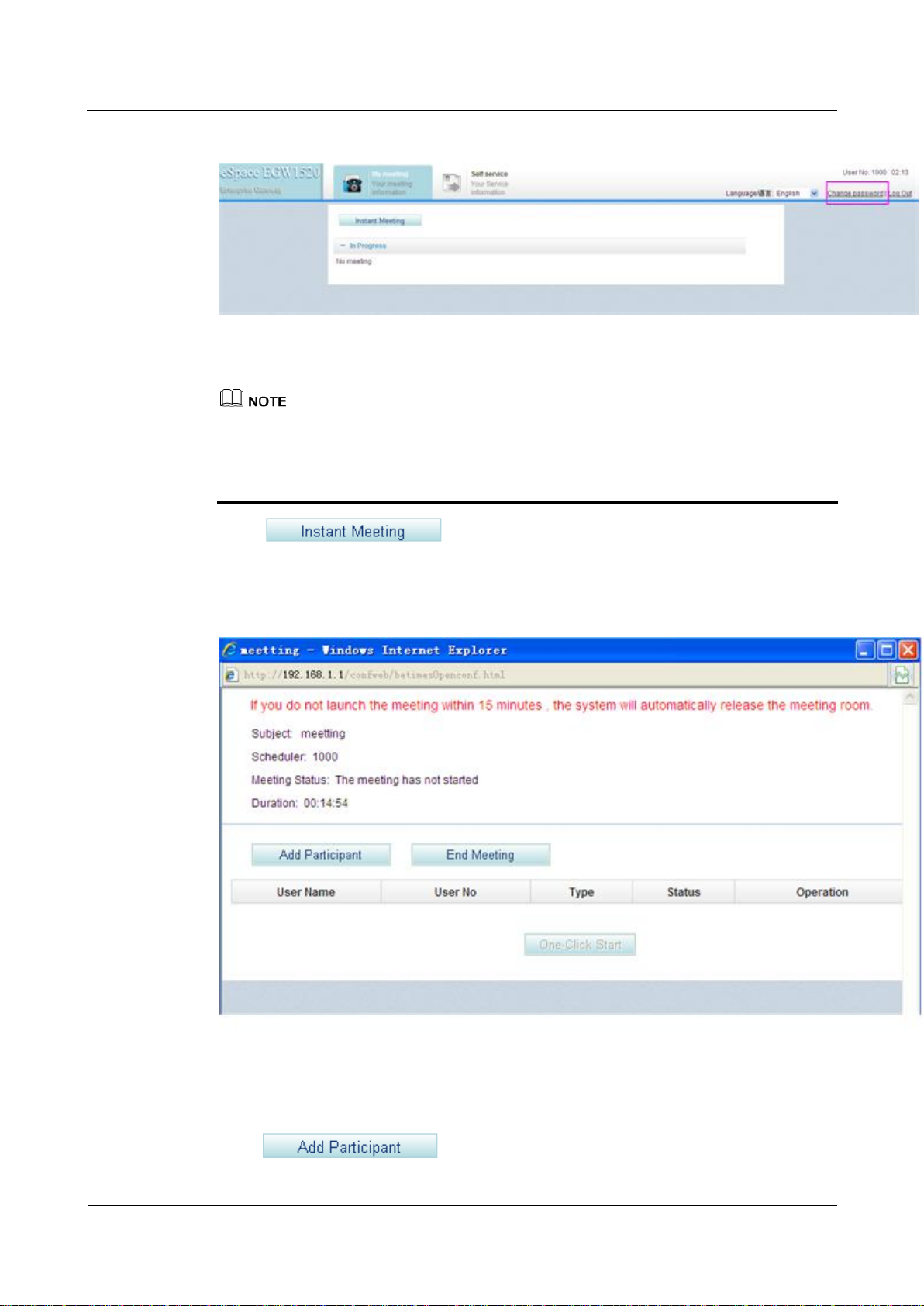
Initiating an Instance Conference Call
Step 1 Log in to the web management system. For details, see 7.7.1 Web Management.
Step 2 Enter the user name and password. (Both the initial user name and password for the
moderator are the moderator's internal number.)
The page shown in Figure 7-156 is displayed.
eSpace EGW1520 Enterprise Gateway
Product Documentation
7 Feature Description and Implementation
Issue 01 (2012-05-15)
Huawei Proprietary and Confidential
Copyright © Huawei Technologies Co., Ltd.
228
Figure 7-156 Conference page
You are advised to change the initial password to ensure security. To change the initial
password, click Change password in Figure 7-156.
If you forget the password, contact the enterprise IT administrator to reset the password.
For details, see Enabling Voice Services.
Step 3 Click .
The page shown in Figure 7-157 is displayed.
Figure 7-157 Joining a conference
Step 4 Click .

eSpace EGW1520 Enterprise Gateway
Product Documentation
7 Feature Description and Implementation
Issue 01 (2012-05-15)
Huawei Proprietary and Confidential
Copyright © Huawei Technologies Co., Ltd.
229
The page shown in Figure 7-158 is displayed.
Figure 7-158 Adding participants
Step 5 Set User Name and User No of a participant.
A participant can be an intra-office or outer-office user (such as a PSTN, IMS, or NGN
user).
To invite an outer-office user to join the conference through the FXO port on EGW1520,
you must set User No based on the FXO dialing rules, such as set User No to the outgoing
prefix and the outer-office user's number.
Step 6 Click to start the conference.
The page shown in Figure 7-159 is displayed.

eSpace EGW1520 Enterprise Gateway
Product Documentation
7 Feature Description and Implementation
Issue 01 (2012-05-15)
Huawei Proprietary and Confidential
Copyright © Huawei Technologies Co., Ltd.
230
Figure 7-159 Conference participants
----End
Self-Service
The self-service function allows users to configure voice services that have been enabled.
Prerequisites
Voice services have been enabled by the enterprise IT administrator.
Using the Self-Service Function
Step 1 Log in to the web management system. For details, see 7.7.1 Web Management.
Step 2 Enter the user name and password. (Both the initial user name and password are a user's
internal number.)
The page shown in Figure 7-160 is displayed.

eSpace EGW1520 Enterprise Gateway
Product Documentation
7 Feature Description and Implementation
Issue 01 (2012-05-15)
Huawei Proprietary and Confidential
Copyright © Huawei Technologies Co., Ltd.
231
Figure 7-160 Self-service
You are advised to change the initial password to ensure security. To change the initial
password, click Change password in Figure 7-160.
If you forget the password, contact the enterprise IT administrator to reset the password.
Step 3 Configure voice services as required. For details, see Configuring and Using Voice Services.
----End
Viewing and Changing Service Prefixes
This topic describes how to view and change service prefixes. Users can configure and use
voice services by dialing service prefixes.
Prerequisites
You have logged in to the web management system. For details, see 7.7.1 Web Management.
Procedure
Step 1 On the web management system, choose Voice > Service Prefix from the navigation tree.
Step 2 Click in the Operation column.
The page shown in Figure 7-161 is displayed.

eSpace EGW1520 Enterprise Gateway
Product Documentation
7 Feature Description and Implementation
Issue 01 (2012-05-15)
Huawei Proprietary and Confidential
Copyright © Huawei Technologies Co., Ltd.
232
Figure 7-161 Current service prefix
For meanings and use of service prefixes, see Configuring and Using Voice Services.
Step 3 Change the service prefix in the Prefix column.

eSpace EGW1520 Enterprise Gateway
Product Documentation
7 Feature Description and Implementation
Issue 01 (2012-05-15)
Huawei Proprietary and Confidential
Copyright © Huawei Technologies Co., Ltd.
233
Country
Emergency call numbers
Ireland
999, 112
New Zealand
111
Service prefix change rule: The asterisk (*) and number sign (#) cannot be changed. You can
change numerals only. Service prefixes related to the voice mailbox cannot contain an asterisk
(*) or a number sign (#). Therefore, a service prefix cannot conflict with any internal numbers,
external numbers (including all outer-office numbers), or emergency numbers. Table 7-36 lists
Ireland's and New Zealand's emergency numbers.
Table 7-36 Ireland's and New Zealand's emergency numbers
Step 4 Click to save the settings.
----End
7.4.2 FXO Port
Description
Principle
This topic describes the principle, implementation, specification, and limitation for the FXO
port on the EGW1520 and how to configure the FXO port.
The EGW1520 provides four FXO ports used to connect to PSTN networks, allowing voice
users on the EGW1520 to communicate with PSTN users.
The EGW1520 provides an FXO port for connecting to the PSTN network. An intra-office
user can dial an outgoing prefix and the number of an outer-office user to make an outgoing
call through the FXO port. An outer-office user dials the number that the PSTN network
carrier allocates to any FXO port of the four FXO ports on the EGW1520 to make an
incoming call.
The EGW1520 supports the switchboard, DDI, and dedicated line functions. By default, the
switchboard function is enabled.
An intra-office user can be a POTS user or a SIP user.
Implementation for the Switchboard
Figure 7-162 shows the application scenario for the switchboard.

eSpace EGW1520 Enterprise Gateway
Product Documentation
7 Feature Description and Implementation
Issue 01 (2012-05-15)
Huawei Proprietary and Confidential
Copyright © Huawei Technologies Co., Ltd.
234
Figure 7-162 Application scenario for the switchboard
The call process for the switchboard is as follows:
Outgoing call
1. An intra-office user dials the outgoing prefix for the FXO port (for example, 0) and the
number of an outer-office user.
2. The EGW1520 automatically queries an idle non-dedicated FXO port for the user to
make the outgoing call.
A non-dedicated FXO port is a port for which the dedicated line is not configured. For details about the
dedicated line, see Implementation for the Dedicated Line.
3. The outer-office user answers the call.
The number that the PSTN network carrier allocates to the FXO port (that is, the switchboard number) is
displayed to the called party.
4. One party hangs up the phone to end the call.
Incoming call
1. An outer-office user dials the number that the PSTN network carrier allocates to the
FXO port, that is, the switchboard number.
The outer-office user hears an announcement, for example, "Thanks for calling XX
company. Please dial the extension number. To query numbers, dial 9. End the number
with a pound key."
2. The outer-office user dials an extension number (internal number) or dials 9 (to connect
to the preset attendant number) as prompted, and presses the pound key (#).
3. The intra-office user or attendant answers the call.
4. One party hangs up the phone to end the call.
Implementation for the DDI
The DDI binds an intra-office user to an FXO port. When an outer-office user makes an
incoming call to the intra-office user through the FXO port, the call is directly connected to
the intra-office user. After the DDI is configured for an FXO port, other users can still make
outgoing calls through the FXO port.

eSpace EGW1520 Enterprise Gateway
Product Documentation
7 Feature Description and Implementation
Issue 01 (2012-05-15)
Huawei Proprietary and Confidential
Copyright © Huawei Technologies Co., Ltd.
235
Figure 7-163 shows the application scenario for the DDI.
Figure 7-163 Application scenario for the DDI
The call process for the DDI is as follows:
Outgoing call
1. An intra-office user dials the outgoing prefix for the FXO port (for example, 0) and the
number of an outer-office user.
2. The EGW1520 automatically queries an idle non-dedicated FXO port for the user to
make the outgoing call.
A non-dedicated FXO port is a port for which the dedicated line is not configured. For details about the
dedicated line, see Implementation for the Dedicated Line.
3. The outer-office user answers the call.
The number that the PSTN network carrier allocates to the FXO port (that is, the switchboard number) is
displayed to the called party.
4. One party hangs up the phone to end the call.
Incoming call
1. An outer-office user dials the number that the PSTN network carrier allocates to the
FXO port.
2. The phone of the DDI user bound to the FXO port (for example, intra-office user 1 in
Figure 7-163) rings.
3. The DDI user answers the call.
4. One party hangs up the phone to end the call.
The number that the PSTN network carrier allocates to the FXO port is displayed to the called party.
Implementation for the Dedicated Line
The dedicated line binds an intra-office user to an FXO port and sets the FXO port to be a
dedicated port. When an outer-office user makes an incoming call to the intra-office user

eSpace EGW1520 Enterprise Gateway
Product Documentation
7 Feature Description and Implementation
Issue 01 (2012-05-15)
Huawei Proprietary and Confidential
Copyright © Huawei Technologies Co., Ltd.
236
through the FXO port, the call is directly connected to the intra-office user. Only the
intra-office user can use the FXO port to make outgoing calls.
Figure 7-164 shows the application scenario for the dedicated line.
Figure 7-164 Application scenario for the dedicated line
The call process for the dedicated line is as follows:
Outgoing call
1. A dedicated user (for example, intra-office user 1 in Figure 7-164) dials the FXO
outgoing prefix (configurable, for example, 0) and an outer-office user's number.
2. The EGW1520 automatically queries the FXO port bound to the user for the user to
make the outgoing call.
If the bound FXO port is unavailable (for example, no phone line is connected to the FXO port), the
EGW1520 automatically queries an idle non-dedicated FXO port for the user to make the outgoing call.
3. The outer-office user answers the call.
The number that the PSTN network carrier allocates to the FXO port is displayed to the called party.
4. One party hangs up the phone to end the call.
Incoming call
1. An outer-office user dials the number that the PSTN network carrier allocates to the
FXO port.
2. The phone of the dedicated user bound to the FXO port (for example, intra-office user 1
in Figure 7-164) rings.
3. The dedicated user answers the call.
4. One party hangs up the phone to end the call.
Specification
Four FXO ports..

eSpace EGW1520 Enterprise Gateway
Product Documentation
7 Feature Description and Implementation
Issue 01 (2012-05-15)
Huawei Proprietary and Confidential
Copyright © Huawei Technologies Co., Ltd.
237
Limitation
Parameter
Description
Prefix
Outgoing prefix for the FXO port. The value is a number consisting of 1
to 30 digits. An intra-office user can dial the outgoing prefix to make an
The FXO port supports only the one-stage dialing mode.
Each FXO port allows one user to make an outgoing or incoming call through the FXO
port at the same time.
Configuring an Outgoing Prefix
This topic describes how to configure an outgoing prefix for the FXO port on the EGW1520.
After the outgoing prefix is configured, an intra-office user can dial the outgoing prefix and
the number of an outer-office user to make an outgoing call through the FXO port.
Prerequisite
You have logged in to the web management system. For details, see 7.7.1 Web Management.
Background
For details about the function of outgoing prefixes and how to use outgoing prefixes, see
Description.
Procedure
Step 1 On the web management system, choose Voice > FXO Configuration from the navigation
tree.
Step 2 Click .
The page shown in Figure 7-165 is displayed.
Figure 7-165 Configuring an outgoing prefix for the FXO port
Step 3 Set parameters according to Table 7-37.
Table 7-37 FXO prefix parameters

eSpace EGW1520 Enterprise Gateway
Product Documentation
7 Feature Description and Implementation
Issue 01 (2012-05-15)
Huawei Proprietary and Confidential
Copyright © Huawei Technologies Co., Ltd.
238
Parameter
Description
outgoing call through the FXO port. Assume that the outgoing prefix is 0
and the number of an outer-office user is 12345678. To call this user, an
intra-office user dials 12345678.
NOTE
A maximum of 16 outgoing prefixes can be configured for the FXO port on the
EGW1520. An intra-office user can use any one of the outgoing prefixes to make
an outgoing call through the FXO port.
The outgoing prefix cannot conflict with internal numbers and emergency
numbers. If an internal number is the same as the outgoing prefix plus an
outer-office number, the internal user is connected.
Delete Yes: The outgoing prefix is deleted for outgoing calls.
Assume that the outgoing prefix is 0 and the number of an outer-office
user is 12345678. To call this user, an intra-office user dials
012345678.
No: The outgoing prefix is not deleted for outgoing calls. This mode
is applicable to the situation where the outgoing prefix is the same as
the first digit in the outer-office number.
Assume that the outgoing prefix is 1 and the number of an outer-office
user is 12345678. To call this user, an intra-office user dials
12345678.
NOTE
The number that the PSTN carrier allocates to the FXO port is displayed to the
called party.
Step 4 Click to save the settings.
----End
Verification
Step 1 An intra-office user dials the outgoing prefix for the FXO port (for example, 0) and the
number of an outer-office user.
Step 2 The outer-office user answers the call.
----End
Verify that the call is set up successfully; otherwise, check the configuration.
Configuring the Switchboard
Prerequisite
This topic describes how to configure the switchboard on the EGW1520.
You have logged in to the web management system. For details, see 7.7.1 Web Management.

eSpace EGW1520 Enterprise Gateway
Product Documentation
7 Feature Description and Implementation
Issue 01 (2012-05-15)
Huawei Proprietary and Confidential
Copyright © Huawei Technologies Co., Ltd.
239
Background
Procedure
For details about the application scenario and call process for the switchboard, see
Description.
The switchboard function conflicts with the DDI and dedicated line functions. If the DDI
or dedicated line function is enabled, choose Voice > FXO Configuration and delete the
binding number on the FXO Toggle tab page before configuring the switchboard function.
The switchboard takes effect automatically after the dedicated line is disabled. No special
configuration is required. The following describe how to configure an attendant number. If
you do not need to configure an attendant number, skip the following procedure.
Default voice prompts are loaded on the EGW1520 before delivery. To customize voice
prompts, see Customizing Voice Prompts for the Switchboard.
If you want to make an outgoing call, configure an outgoing prefix when you configure the switchboard.
For the configuration method, see Configuring an Outgoing Prefix.
Step 1 On the web management system, choose Voice > FXO Configuration from the navigation
tree.
Step 2 Click the Operator Configure tab.
The page shown in Figure 7-166 is displayed.
Figure 7-166 Configuring an attendant
Step 3 Click .
The page shown in Figure 7-167 is displayed.

eSpace EGW1520 Enterprise Gateway
Product Documentation
7 Feature Description and Implementation
Issue 01 (2012-05-15)
Huawei Proprietary and Confidential
Copyright © Huawei Technologies Co., Ltd.
240
Figure 7-167 Selecting a user
Step 4 Select an internal number as the attendant number, and click .
Step 5 Click to save the settings.
Verification
Step 1 An outer-office user dials the number that the PSTN network carrier allocates to the FXO port,
Step 2 The outer-office user dials an extension number (internal number) or dials 9 (to connect to the
Step 3 The intra-office user or attendant answers the call.
For details about how to add an internal number, see Adding Voice Users.
----End
Incoming call
that is, the switchboard number.
preset attendant number) as prompted, and presses the pound key (#).
----End
Verify that the call is set up successfully; otherwise, check the configuration.
Outgoing call

eSpace EGW1520 Enterprise Gateway
Product Documentation
7 Feature Description and Implementation
Issue 01 (2012-05-15)
Huawei Proprietary and Confidential
Copyright © Huawei Technologies Co., Ltd.
241
Step 1 An intra-office user dials the outgoing prefix for the FXO port (for example, 0) and the
number of an outer-office user.
Step 2 The outer-office user answers the call.
----End
Verify that the call is set up successfully; otherwise, check the configuration.
Configuring the DDI and Dedicated Line
This topic describes how to configure the DDI and dedicated line on the EGW1520.
Prerequisite
You have logged in to the web management system. For details, see 7.7.1 Web Management.
Background
For details about the application scenario and call process for the DDI and dedicated line, see
Description.
The priority of the DDI or dedicated line is higher than that of the switchboard. When the DDI or
dedicated line is configured, the switchboard automatically becomes invalid.
Procedure
Step 1 On the web management system, choose Voice > FXO Configuration from the navigation
Step 2 Click the FXO Toggle tab.
If you want to make an outgoing call, configure an outgoing prefix when you configure the DDI and
dedicated line. For the configuration method, see Configuring an Outgoing Prefix.
tree.
The page shown in Figure 7-168 is displayed.
Figure 7-168 Configuring the FXO binding number
Step 3 Select the FXO port you want to configure, set parameters according to Table 7-38.

eSpace EGW1520 Enterprise Gateway
Product Documentation
7 Feature Description and Implementation
Issue 01 (2012-05-15)
Huawei Proprietary and Confidential
Copyright © Huawei Technologies Co., Ltd.
242
Parameter
Description
Toggle Number
Internal number bound to the FXO port.
NOTE
For details about how to add an internal number,
see Adding Voice Users.
Private Line
Indicates whether to enable the dedicated
line function.
Step 4 Click to save the settings.
Verification
Step 1 An outer-office user dials the number that the PSTN network carrier allocates to the FXO
Table 7-38 Configuring the DDI and dedicated line
----End
Incoming call
port.
Step 2 The phone of the intra-office user whose number is bound to the FXO port rings.
Step 3 The intra-office user answers the call.
----End
Verify that the call is set up successfully; otherwise, check the configuration.
Outgoing call
Step 1 The intra-office user whose number is bound to the FXO port dials the outgoing prefix for the
FXO port (for example, 0) and the number of an outer-office user.
Step 2 The outer-office user answers the call.
----End
Verify that the call is set up successfully; otherwise, check the configuration.
7.4.3 Power-off Survival
The FXO1 port of the EGW1520 can be used as a power-off survival port. When the
EGW1520 is powered off, the analog phone connected to the PHONE port can be connected
to the PSTN through the FXO1 port.
Principle and Implementation
When the EGW1520 is powered off, the PHONE port automatically connects to the FXO1
port.

eSpace EGW1520 Enterprise Gateway
Product Documentation
7 Feature Description and Implementation
Issue 01 (2012-05-15)
Huawei Proprietary and Confidential
Copyright © Huawei Technologies Co., Ltd.
243
Generally, the EGW1520 power-off survival function is available once the cables are
connected. You do not need to configure the function on the web management system. The
cables are connected as follows:
The FXO1 port on the EGW1520 has been connected to the PSTN.
An analog phone has been connected to the PHONE port on the EGW1520.
When the EGW1520 is powered off, it automatically connects the analog phone connected to
the PHONE port to the PSTN, as shown in Figure 7-169.
Figure 7-169 Power-off survival
When the power-off survival function is enabled, the number of the analog phone
connected to the PHONE port changes from the external number to the FXO1 port number,
and the dialing rule changes from the EGW1520 dialing rule to the PSTN dialing rule.
After the power-off survival function is enabled, the ongoing call does not end after the
EGW1520 powers on again, but the voice services cannot be used until the call ends.
After the power-off survival function is enabled, the FXO switchboard, DDI, and
dedicated line functions cannot be used.
To verify that the power-off survival function is enabled, perform the following steps:
1. Cut the power supply of the EGW1520.
2. Use an analog phone that is connected to the PHONE port to call an external number.
If the call is connected, the power-off survival function is enabled. If the call is disconnected,
check the connections between the PHONE port and the analog phone, and between the
EGW1520 FXO1 port and the PSTN.
Specification
One PSTN Power-off survival port.

eSpace EGW1520 Enterprise Gateway
Product Documentation
7 Feature Description and Implementation
Issue 01 (2012-05-15)
Huawei Proprietary and Confidential
Copyright © Huawei Technologies Co., Ltd.
244
Limitation
7.4.4 Fax Service
Description
The Power-off survival function is available only when a power off occurs.
Only the Analog Phone that connects to the PHONE port supports Power-off survival
function.
The EGW1520 supports fax service.
Fax is a form of telegraphy for the transmission of fixed images with a view to their
reproduction in a permanent form. In ITU-RV.662, faxing is defined as a form of
telecommunication for the reproduction at a distance of graphic documents in the form of
other graphic documents geometrically similar to the original.
This topic describes the principle, implementation, specification, and limitation of the fax
service.
By transmission rate, faxes are divided into low-speed faxes (<= 14.4 kbit/s) and high-speed
faxes (> 14.4 kbit/s).
Low-speed faxes on an IP network are divided into transparently transmitted faxes (using
G.711A or G.711u) and T.38 faxes. High-speed faxes, however, can only use G.711A or G.711u
featuring low compression rate due to the requirement for high quality.
Principle
The EGW1520 supports T.38 and transparent fax.
The fax service establishes a voice channel and switches the voice channel to a fax channel,
including the IP address, port, codec, and channel types (audio, fax, and data).
The voice channel is switched to a fax channel after the access device detects fax signals. The
access device checks fax signals to determine whether the current fax is a high-speed or
low-speed fax, and then delivers the fax signals to the NGN or IMS.
The EGW1520 supports T.38 and transparent fax.
Transparent fax: Fax signals are transmitted transparently as G.711 packets. G.711 faxes
feature low delay and simple implementation, but they occupy a high bandwidth (fixed at 64
kbit/s) and are easily affected by network conditions. Therefore, G.711 faxes are
recommended on a good network condition and not recommended when network jitter or
packet loss frequently occur. G.711 faxes are applicable to high-speed and low-speed faxes.
T.38 fax: T.30 fax signals are converted to T.38 packets for transmission on a packet switching
network. T.38 faxes occupy a low bandwidth, provide high reliability with redundant frames
and forward error checking (FEC), and are slightly affected by the network condition.
However, the implementation is complicated. T.38 faxes are applicable only to low-speed fax
services due to delay generated by the packet switching network.
Implementation
When a fax machine connected to the EGW1520 communicates with an outer-office machine,
the NGN or IMS controls the call process. Figure 7-170 shows the network diagram.

eSpace EGW1520 Enterprise Gateway
Product Documentation
7 Feature Description and Implementation
Issue 01 (2012-05-15)
Huawei Proprietary and Confidential
Copyright © Huawei Technologies Co., Ltd.
245
Figure 7-170 EGW1520 outer-office faxing
Specification
Limitation
The NGN or IMS controls call signaling. The EGW1520 detects fax signals and encodes and
decodes IP voice packets. After a fax call is established, fax media streams are transmitted
over an IP network. The process for making a fax call is similar to that for making an
inter-office call. After the fax call is complete, the EGW1520 detects the fax ending signals
and sends them to the NGN or IMS. The NGN or IMS negotiates with the calling and called
users about the fax media information. After the negotiation is successful, the EGW1520
switches to the fax channel according to the NGN or IMS's signaling to establish a fax call.
After the fax call is complete, the EGW1520 detects the fax ending signals and sends them to
the NGN or IMS. Then the NGN or IMS switches to the voice channel.
Standards supported by fax service:
One FXS ports for fax machines
T.30
T.38
V.17/V.21/V.27/V.29/V.34
N/A
Configuring the Fax Service
Generally, the EGW1520 faxing function is available once the cables are connected, you do
not need to configure the function on the web management system. This topic describes how
to set the advanced parameters for faxing.

eSpace EGW1520 Enterprise Gateway
Product Documentation
7 Feature Description and Implementation
Issue 01 (2012-05-15)
Huawei Proprietary and Confidential
Copyright © Huawei Technologies Co., Ltd.
246
Prerequisites
You have logged in to the web management system. For details, see 7.7.1 Web Management.
Configuring the Priority
Step 1 On the web management system, choose Voice > Voice Parameters from the navigation tree.
Step 2 Click the DSP tab.
The page shown in Figure 7-171 is displayed.
Figure 7-171 DSP tab page
Step 3 Set parameters according to Table 7-39.

eSpace EGW1520 Enterprise Gateway
Product Documentation
7 Feature Description and Implementation
Issue 01 (2012-05-15)
Huawei Proprietary and Confidential
Copyright © Huawei Technologies Co., Ltd.
247
Table 7-39 DSP parameters
Parameter
Description
Codec
DSP codec type. If multiple options are selected, the system sends
messages based on the specified codec rank. By default, all options
are selected.
NOTE
Compared with other codec types, G729, G726, and G722 consume more
DSP resources.
Codec Ptime (ms)
For each codec type, you can change the duration of packaging
voice streams to 10 ms, 20 ms, or 30 ms. The default value is 20
ms.
Echo Cancellation
Indicates the echo cancellation switch. The options are Enable and
Disable, and the default value is Enable.
The high-speed transparent transmission mode has the echo
processing mechanism. You are advised to disable the echo
cancellation function for the high-speed transparent transmission
mode and enable this function for low-speed transparent
transmission mode.
Enable Silence
Suppress
Indicates the silence suppression switch. The options are Enable
and Disable. The default value is Enable, which indicates that the
system sends silence packets if no voice packet is available.
Receive Gain (dB)
Indicates the receiving gain of DSP chips. The value ranges from
–14 to 6. The default value is 0.
Send Gain (dB)
Indicates the sending gain of DSP chips. The value ranges from
–14 to 6. The default value is 0.
Fax Prior Mode
Indicates the fax transmission mode. The options are as follows:
T38: Only T38 is supported.
VBD: Only voice band data (VBD) is supported.
T38-VBD: Both T38 and VBD are supported, and T38 has a
higher priority.
VBD-T38: Both T38 and VBD are supported, and VBD has a
higher priority.
The default value is VBD-T38.
Media Negotiation
Mode
Indicates the priority used in media negotiation.
Prefer remote codec: During media negotiation, the codec
priority at the remote end is preferred.
Prefer local codec: During media negotiation, the codec priority
at the local end is preferred.
The default value is Prefer remote codec.
DTMF Transfer
Mode
Indicates the transmission mode in a session.
RFC2833: RFC2833 transmission mode.
Transfer: transparent transmission mode. Dialing tones are
transmitted transparently as voice signals.

eSpace EGW1520 Enterprise Gateway
Product Documentation
7 Feature Description and Implementation
Issue 01 (2012-05-15)
Huawei Proprietary and Confidential
Copyright © Huawei Technologies Co., Ltd.
248
Parameter
Description
The default value is RFC2833.
VBD Mode
Indicates the codec type for transparent transmission. The options
are G711A and G711U, and the default value is G711A.
Parameter
Description
Fax Rate
Indicates the faxing rate mode. Value transferredTcf indicates
remote training mode.
UDPEC
Indicates the UDP redundancy correction capability. The
EGW1520 supports t38udpredundancy. If the redundancy
correction capability is carried in fax negotiation signals, the
EGW1520 uses the redundancy technology to send T38 data when
the peer end also supports redundancy.
Max Rate
Indicates the maximum faxing rate. If the maximum faxing rate at
the peer end is smaller than that at the local end, use the smaller
one; otherwise, use the value of this parameter.
Step 4 Click to save the settings.
----End
Viewing T38 Fax Parameters
Step 1 On the web management system, choose Voice > Voice Parameters from the navigation tree.
Step 2 Click the T38 tab.
The page shown in Figure 7-172 is displayed.
Figure 7-172 T38 tab page
Step 3 Set parameters according to Table 7-40.
Table 7-40 T.38 fax parameters

eSpace EGW1520 Enterprise Gateway
Product Documentation
7 Feature Description and Implementation
Issue 01 (2012-05-15)
Huawei Proprietary and Confidential
Copyright © Huawei Technologies Co., Ltd.
249
Parameter
Description
Transport Protocol
Indicates the transmission protocol. The EGW1520 supports UDP.
----End
7.4.5 Voice Parameters
This topic describes how to set voice parameters. Only network administrators can change the
parameter settings. To ensure the normal running of the EGW1520, you are advised to use the
default settings.
Prerequisites
You have logged in to the web management system. For details, see 7.7.1 Web Management.
Configuring the Region
On the Region tab page, specify analog phone standards in different countries. Dialing tones
and signal tone frequency vary according to area and country. Configure the parameters based
on requirement.
Step 1 On the web management system, choose Voice > Voice Parameters from the navigation tree.
The page shown in Figure 7-173 is displayed.
Figure 7-173 Region tab page

eSpace EGW1520 Enterprise Gateway
Product Documentation
7 Feature Description and Implementation
Issue 01 (2012-05-15)
Huawei Proprietary and Confidential
Copyright © Huawei Technologies Co., Ltd.
250
Step 2 Set parameters according to Table 7-41.
Parameter
Description
Current Country
Country name.
Slic Gain RX (dB)
Receiving gain of an analog phone. The value ranges from -12 dB
to +6 dB.
Slic Gain TX (dB)
Sending gain of an analog phone. The value ranges from -12 dB to
+6 dB.
FlashHook Max (ms)
Maximum interval for pressing the hook flash button. The value
ranges from 0 to 1000, in milliseconds. If the hook flash button is
not pressed within the duration specified by this parameter, the
call will end.
FlashHook Min (ms)
Minimum interval for pressing the hook flash button. The value
ranges from 0 to 1000, in milliseconds. If the interval is smaller
than the value of this parameter, the hook flash operation does not
take effect.
OnHook Min (ms)
Minimum interval for confirming hang-up. The value ranges from
0 to 2000, in milliseconds. If the hang-up interval is smaller than
the value of this parameter, the hang-up operation does not take
effect.
OffHook Min (ms)
Minimum interval for confirming pickup. The value ranges from 0
to 2000, in milliseconds. If the pickup interval is smaller than the
value of this parameter, the pickup operation does not take effect.
Table 7-41 Region parameters
Step 3 Click to save the settings.
----End
Configuring the DSP
On the DSP tab page, configure voice quality information about DSP chips, such as codec
type, noise and echo cancellation, silence suppression, and gains.
Step 1 On the web management system, choose Voice > Voice Parameters from the navigation tree.
Step 2 Click the DSP tab.
The page shown in Figure 7-174 is displayed.

eSpace EGW1520 Enterprise Gateway
Product Documentation
7 Feature Description and Implementation
Issue 01 (2012-05-15)
Huawei Proprietary and Confidential
Copyright © Huawei Technologies Co., Ltd.
251
Figure 7-174 DSP tab page
Parameter
Description
Codec
DSP codec type. If multiple options are selected, the system sends
messages based on the specified codec rank. By default, all options
are selected.
NOTE
Compared with other codec types, G729, G726, and G722 consume more
DSP resources.
Codec Ptime (ms)
For each codec type, you can change the duration of packaging
voice streams to 10 ms, 20 ms, or 30 ms. The default value is 20
ms.
Echo Cancellation
Echo cancellation switch. The options are Enable and Disable,
and the default value is Enable.
Step 3 Set parameters according to Table 7-42.
Table 7-42 DSP parameters

eSpace EGW1520 Enterprise Gateway
Product Documentation
7 Feature Description and Implementation
Issue 01 (2012-05-15)
Huawei Proprietary and Confidential
Copyright © Huawei Technologies Co., Ltd.
252
Parameter
Description
Enable Silence
Suppress
Silence suppression switch. The options are Enable and Disable.
The default value is Enable, which indicates that the system sends
silence packets if no voice packet is available.
Receive Gain (dB)
Receiving gain of DSP chips. The value ranges from -14 to 6. The
default value is 0.
Send Gain (dB)
Sending gain of DSP chips. The value ranges from -14 to 6. The
default value is 0.
Fax Prior Mode
Fax transmission mode. The options are as follows:
T38: Only T38 is supported.
VBD: Only voice band data (VBD) is supported.
T38-VBD: Both T38 and VBD are supported, and T38 has a
higher priority.
VBD-T38: Both T38 and VBD are supported, and VBD has a
higher priority.
The default value is VBD-T38.
Media Negotiation
Mode
Priority used in media negotiation.
Prefer remote codec: During media negotiation, the codec
priority at the remote end is preferred.
Prefer local codec: During media negotiation, the codec priority
at the local end is preferred.
The default value is Prefer remote codec.
DTMF Transfer
Mode
Transmission mode in a session.
RFC283: RFC2833 transmission mode.
Transfer: transparent transmission mode. Dialing tones are
transmitted transparently as voice signals.
The default value is RFC2833.
VBD Mode
Codec type for transparent transmission. The options are G711A
and G711U, and the default value is G711A.
Step 4 Click to save the settings.
----End
Configuring RTP
On the RTP tab page, set the parameters used for playing voices on analog phones such as the
maximum and minimum media port numbers.
Step 1 On the web management system, choose Voice > Voice Parameters from the navigation tree.
Step 2 Click the RTP tab.
The page shown in Figure 7-175 is displayed.

eSpace EGW1520 Enterprise Gateway
Product Documentation
7 Feature Description and Implementation
Issue 01 (2012-05-15)
Huawei Proprietary and Confidential
Copyright © Huawei Technologies Co., Ltd.
253
Figure 7-175 RTP tab page
Parameter
Description
Min UDP Port
Minimum media port number used for playing voices on
analog phones.
Max UDP Port
Maximum media port number used for playing voices on
analog phones.
DTMF (RFC2833)
Whether RFC2833 is used for encryption. The options are
Enable and Disable.
Payload Type: payload for RFC2833 used for encryption. The
value must be unique on the EGW1520. It is recommended that
you set this parameter to the payload type of the softswitch. If
the parameter value is different from that on the softswitch, call
connections may fail to be set up.
RTCP
Whether to enable the RTCP function. The options are Enable
and Disable. The default value is Disable.
Step 3 Set parameters according to Table 7-43.
Table 7-43 RTP parameters
After changing the UDP port number, restart the device to make the configuration take effect.
Step 4 Click to save the settings.
----End

eSpace EGW1520 Enterprise Gateway
Product Documentation
7 Feature Description and Implementation
Issue 01 (2012-05-15)
Huawei Proprietary and Confidential
Copyright © Huawei Technologies Co., Ltd.
254
Viewing T38 Fax Parameters
Parameter
Description
Fax Rate
Faxing rate mode. Value transferredTcf indicates remote training
mode.
UDPEC
UDP redundancy correction capability. The EGW1520 supports
t38udpredundancy. If the redundancy correction capability is
carried in fax negotiation signals, the EGW1520 uses the
redundancy technology to send T38 data when the peer end also
supports redundancy.
Max Rate
Maximum faxing rate. If the maximum faxing rate at the peer end
is smaller than that at the local end, use the smaller one; otherwise,
use the value of this parameter.
Transport Protocol
Transmission protocol. The EGW1520 supports UDP.
On the T38 tab page, you can view T.38 fax parameters.
Step 1 On the web management system, choose Voice > Voice Parameters from the navigation tree.
Step 2 Click the T38 tab.
The page shown in Figure 7-176 is displayed.
Figure 7-176 T38 tab page
Step 3 Set parameters according to Table 7-44.
Table 7-44 T38 fax parameters
----End
Configuring SIP
On the SIP tab page, configure the timeout interval for local SIP users to register with the
EGW1520.
Step 1 On the web management system, choose Voice > Voice Parameters from the navigation tree.

eSpace EGW1520 Enterprise Gateway
Product Documentation
7 Feature Description and Implementation
Issue 01 (2012-05-15)
Huawei Proprietary and Confidential
Copyright © Huawei Technologies Co., Ltd.
255
Step 2 Click the SIP tab.
Parameter
Description
SIP Register Expire
(s)
Timeout interval for local SIP users to register with the EGW1520.
Min: Minimum timeout interval for local SIP users to register
with the EGW1520. The default value is 120.
Max: Maximum timeout interval for local SIP users to register
with the EGW1520. The default value is 3600.
Local Subscribe
Expire (s)
Timeout interval for local SIP users to subscribe to a service (such as
voice message and voice mailbox) with the EGW1520
Min: Minimum timeout interval for local SIP users to subscribe
to a service with the EGW1520. The default value is 120.
Max: Maximum timeout interval for local SIP users to subscribe
to a service with the EGW1520. The default value is 3600.
Network Subscribe
Expire (s)
Default timeout interval for the EGW1520 to subscribe to a service
with the NGN or IMS.
SIP Session Timer
Whether to use the session timer. The session timer is disabled by
default. When the session timer is enabled, the two parties can check
the conversation status using the update or reinvite signaling.
The page shown in Figure 7-177 is displayed.
Figure 7-177 SIP tab page
Step 3 Set parameters according to Table 7-45.
Table 7-45 SIP parameters
Step 4 Click to save the settings.
----End

eSpace EGW1520 Enterprise Gateway
Product Documentation
7 Feature Description and Implementation
Issue 01 (2012-05-15)
Huawei Proprietary and Confidential
Copyright © Huawei Technologies Co., Ltd.
256
Configuring SIP ALG
Parameter
Description
Server port
Master: Port number used by the active SIP server to send and
receive packets.
Slave: Port number used by the standby SIP server to send and
receive packets.
Extended: Extended port number used by the SIP ALG to send
and receive packets.
RTP port
Min: Minimum media port that can be used by the RTP server.
Max: Maximum media port that can be used by the RTP server.
On the SIP ALG tab page, configure SIP servers in an outer office.
Step 1 On the web management system, choose Voice > Voice Parameters from the navigation tree.
Step 2 Click the SIP ALG tab.
The page shown in Figure 7-178 is displayed.
Figure 7-178 SIP ALG tab page
Step 3 Set parameters according to Table 7-46.
Table 7-46 SIP ALG parameters
Step 4 Click to save the settings.
----End

eSpace EGW1520 Enterprise Gateway
Product Documentation
7 Feature Description and Implementation
Issue 01 (2012-05-15)
Huawei Proprietary and Confidential
Copyright © Huawei Technologies Co., Ltd.
257
7.5 Data
This topic describes EGW1520 data features and how to configure the features.
7.5.1 LAN
The EGW1520 provides four LAN ports to connect terminals such as computers and IP
phones. In addition, the EGW1520 can function as a Dynamic Host Configuration Protocol
(DHCP) server to allocate private IP addresses to terminals. After network address translation
(NAT), terminals are connected to the IP network and the IP network connects the terminals to
the Internet or IMS/NGN.
Description
This topic describes the principle, implementation, specification, and limitation of LAN ports.
Principle
The EGW1520 complies with IEEE802.3u 100Base-T.
Implementation
The EGW1520 provides four LAN ports to connect terminals such as computers and IP
phones, as shown in Figure 7-179. The EGW1520 can function as a DHCP server to allocate
private IP addresses to terminals. After NAT, terminals are connected to the IP network and
the IP network connects the terminals to the Internet, IMS, or NGN.
Figure 7-179 LAN diagram

eSpace EGW1520 Enterprise Gateway
Product Documentation
7 Feature Description and Implementation
Issue 01 (2012-05-15)
Huawei Proprietary and Confidential
Copyright © Huawei Technologies Co., Ltd.
258
Specification
For details about the DHCP server and trunk, see the DHCP Feature Description.
Four 10/100 Mbit/s self-adaptive LAN ports.
Default IP address of LAN ports: 192.168.1.1; subnet mask: 255.255.255.0.
DHCP server function, allocating IP addresses to computers and IP phones that connect
to LAN ports.
Standards supported by LAN ports:
− MAC Address (IEEE 802.3)
− IPv4 Internet Protocol v4 (RFC 791)
− ARP Address Resolution Protocol (RFC 826)
− ICMP Internet Control Message Protocol (RFC 792)
− An Ethernet Address Resolution Protocol (RFC 0826)
− A Standard for the Transmission of IP Datagrams over Ethernet Networks (RFC
0894)
− A Standard for the Transmission of IP Datagrams over IEEE 802 Networks (RFC
1042)
− DHCP (RFC 2131), TCP Transmission Control Protocol (RFC 793)
− UDP User Datagram Protocol (RFC 768)
Limitation
The LAN port supports half-duplex and full-duplex self adaptation, but cannot be forced
to use full duplex or half duplex.
IPv6 is not supported.
Configuration
This topic describes how to configure a LAN.
Prerequisites
You have logged in to the web management system. For details, see 7.7.1 Web Management.
Background
LAN configuration for the EGW1520 includes:
Set the IP address of the LAN gateway. For details, see Setting the IP Address of the
LAN Gateway.
Configure the EGW1520 as the DHCP server or DHCP relay. For details, see
Configuring the DHCP Server and Configuring the DHCP Relay.
Setting the IP Address of the LAN Gateway
Terminals such as PCs and IP phones use the IP address of the LAN gateway to communicate
with other networks and to connect to the EGW1520.
The default IP address of the LAN gateway is 192.168.1.1.

eSpace EGW1520 Enterprise Gateway
Product Documentation
7 Feature Description and Implementation
Issue 01 (2012-05-15)
Huawei Proprietary and Confidential
Copyright © Huawei Technologies Co., Ltd.
259
Step 1 On the web management system, choose Network > LAN from the navigation tree.
Parameter
Description
IP Address
Indicates the IP address of the LAN gateway. Terminals use it to
connect to the LAN port on the EGW1520. The default value is
192.168.1.1. You can change this value.
CAUTION
The IP addresses of the LAN gateway, ADSL port, and WAN port
cannot be on the same network segment.
The IP address of the LAN gateway cannot conflict with that of any
other device on the same network segment.
Subnet Mask
Indicates the subnet mask of the IP address of the LAN gateway.
The default value is 255.255.255.0.
Web Access Mode
Indicates the protocol that is used to access the web page of the
EGW1520.
Http: The web browser interacts with the EGW1520 using
HTTP.
Https: The web browser interacts with the EGW1520 using
HTTPS, which ensures user information security.
The HTTPS protocol is used by default.
LAN Side Firewall
Enable: Enable the firewall on the LAN side.
The page shown in Figure 7-180 is displayed.
Figure 7-180 Setting the IP address of the LAN gateway
Step 2 Set parameters according to Table 7-47.
Table 7-47 Parameter description

eSpace EGW1520 Enterprise Gateway
Product Documentation
7 Feature Description and Implementation
Issue 01 (2012-05-15)
Huawei Proprietary and Confidential
Copyright © Huawei Technologies Co., Ltd.
260
Parameter
Description
NOTE
When this function is enabled, the firewall blocks all packets that are sent
to the upstream network or the EGW1520 over the LAN network. To
allow specified packets to pass the firewall, choose Advanced > Security
and set related parameters on the Filter incoming IP tab page.
Disable: Disable the firewall on the LAN side.
By default, this function is disabled.
LAN Side ICMP
Enable: ICMP packets on the LAN side can be sent to the
EGW1520.
Disable: ICMP packets on the LAN side cannot be sent to the
EGW1520.
By default, this function is enabled.
----End
Configuring the DHCP Server
After you configure the EGW1520 as the DHCP server, terminals such as PCs and IP phones
that connect to the EGW1520 obtain the IP address information through the EGW1520.
Step 1 Click Advanced on the LAN Setup page.
The page shown in Figure 7-181 is displayed.

eSpace EGW1520 Enterprise Gateway
Product Documentation
7 Feature Description and Implementation
Issue 01 (2012-05-15)
Huawei Proprietary and Confidential
Copyright © Huawei Technologies Co., Ltd.
261
Figure 7-181 Configuring the DHCP server (1)
Parameter
Description
Start IP Address
Indicates the start IP address in the address pool. It must be on the
same network segment as the LAN gateway. The default value is
recommended.
End IP Address
Indicates the end IP address in the address pool. It must be on the
same network segment as the LAN gateway. The default value is
recommended.
Leased Time (hour)
Indicates the IP address lease interval. If the lease expires and the
DHCP client does not renew the lease, the DHCP server releases
the IP addresses that are granted to the DHCP client for other
clients.
Step 2 Set parameters according to Table 7-48.
Table 7-48 Parameter description

eSpace EGW1520 Enterprise Gateway
Product Documentation
7 Feature Description and Implementation
Issue 01 (2012-05-15)
Huawei Proprietary and Confidential
Copyright © Huawei Technologies Co., Ltd.
262
Step 3 (Optional) Allocate IP addresses by binding them with MAC addresses statically.
After configuration, the DHCP server finds the IP address based on the bound MAC address
and allocates the IP address to the corresponding DHCP client. This mode is applicable to
clients that require a fixed IP address such as the FTP server.
1. Click .
The page shown in Figure 7-182 is displayed.
Figure 7-182 Configuring the DHCP server (2)
2. Enter the MAC address of the DHCP client and the IP address that you want to bind with
the MAC address.
3. Click to save the settings.
To obtain the MAC address of a PC, choose Start > Run, type cmd, and press Enter. On
the command-line interface (CLI) that is displayed, run the ipconfig /all command. The
value of Physical Address corresponding to the 192.168.x.y indicates the MAC address.
To obtain the MAC address of other network devices such as IP phones, see the related
document.
Step 4 Click to save the settings.
----End
Configuring the DHCP Relay
If the DHCP server has been deployed but it is on a different network segment from terminals
(such as PCs and IP phones), configure the EGW1520 as the DHCP relay. After configuration,
the EGW1520 forwards terminals' DHCP requests to the DHCP server. The DHCP server
sends the IP address allocation information to the EGW1520, and the EGW1520 forwards the
information to terminals.
The DHCP client enables terminals that connect to the EGW1520 and DHCP clients on other
networks to use the same DHCP server. This reduces costs and simplifies management.

eSpace EGW1520 Enterprise Gateway
Product Documentation
7 Feature Description and Implementation
Issue 01 (2012-05-15)
Huawei Proprietary and Confidential
Copyright © Huawei Technologies Co., Ltd.
263
The DHCP relay conflicts with the NAT function. Before configuring the EGW1520 as the DHCP
relay, you must disable the NAT function.
When configuring the EGW1520 as the DHCP relay, ensure that a reachable route exists between the
EGW1520 and DHCP server.
Step 1 Click Enable DHCP Server Relay, as shown in Figure 7-183.
Figure 7-183 Configuring the DHCP relay
Step 2 Enter the IP address of the DHCP server.
Step 3 Click to save the settings.
----End
LAN Setting Example (EGW1520 as DHCP Server)
Network Requirements
PCs use the LAN switch to connect to the LAN port on the EGW1520, while the IP
phone and FTP server connect to the LAN port on the EGW1520 directly.
The EGW1520 functions as the DHCP server and automatically allocates IP addresses
for the PCs, IP phone, and FTP server.
After configuration, the FTP server obtains a fixed IP address, while the IP phone and
PCs obtain dynamic IP addresses through the EGW1520.
Typical Network
Figure 7-184 shows the typical network.

eSpace EGW1520 Enterprise Gateway
Product Documentation
7 Feature Description and Implementation
Issue 01 (2012-05-15)
Huawei Proprietary and Confidential
Copyright © Huawei Technologies Co., Ltd.
264
Figure 7-184 Typical network (1)
Procedure
Step 1 Configure that the FTP server, IP phone, and PCs obtain IP addresses automatically. For
details, see the related user guide.
Step 2 Configure the EGW1520 as the DHCP server. For details, see step 1 in Configuring the
DHCP Server.
Step 3 Query and record the MAC address of the FTP server. For details, see Obtain the MAC
address.
Step 4 Allocate the IP address that is bound to the MAC address to the FTP server. For details, see
step 2 in Configuring the DHCP Server.
----End
Verification
Verify that the FTP server, PCs, and IP phone have obtained IP addresses and that IP address
that the FTP server obtains is bound to its MAC address.
LAN Setting Example (EGW1520 as DHCP Relay)
Network Requirements

eSpace EGW1520 Enterprise Gateway
Product Documentation
7 Feature Description and Implementation
Issue 01 (2012-05-15)
Huawei Proprietary and Confidential
Copyright © Huawei Technologies Co., Ltd.
265
The DHCP server (IP address: 192.168.2.1) is deployed on the network. The LAN port
on the EGW1520 connects to the DHCP server through a router.
The PCs, IP phone, and FTP server directly connect to the LAN port on the EGW1520.
The EGW1520 functions as the DHCP relay and allocates IP addresses for the PCs, IP
phone, and FTP server.
After configuration, the FTP server obtains a fixed IP address, while the IP phone and
PCs obtain dynamic IP addresses through the EGW1520.
Typical Network
Figure 7-185 shows the typical network.
Figure 7-185 Typical network (2)
Procedure
Step 1 Configure that the FTP server, IP phone, and PCs obtain IP addresses automatically. For
details, see the related user guide.
Step 2 Configure the EGW1520 as the DHCP relay, and set the IP address of the DHCP server to
192.168.2.1. For details, see Configuring the DHCP Relay.
Step 3 Add a static route on the EGW1520, and set the destination network segment to
192.168.2.0/24. For details, see 7.5.5 Static Route.
Step 4 Set the gateway IP address to 192.168.2.2/24 on the DHCP server. For details, see the DHCP
server user guide.

eSpace EGW1520 Enterprise Gateway
Product Documentation
7 Feature Description and Implementation
Issue 01 (2012-05-15)
Huawei Proprietary and Confidential
Copyright © Huawei Technologies Co., Ltd.
266
Step 5 Add an address pool whose start IP address is 192.168.1.0 and end IP address is 192.168.1.24
7.5.2 DHCP
Description
for the DHCP server, and allocate the IP address that is bound to the MAC address to the FTP
server. For details, see the DHCP server user guide.
----End
Verification
Verify that the FTP server, PCs, and IP phone have obtained IP addresses in the network
segment 192.168.1.0/24, and that IP address that the FTP server obtains is bound to its MAC
address.
Dynamic Host Configuration Protocol (DHCP) is a protocol for dynamically managing and
configuring users in a centralized manner. It uses the Client/Server structure. A DHCP client
sends the DHCP server a request to apply for parameter settings, including the IP address,
subnet mask, and default gateway. Then the DHCP server sends the parameter settings to the
DHCP client. The EGW1520 can function as a DHCP server or a DHCP relay to allocate IP
addresses to PCs, IP phones, and Wi-Fi terminals that are connected to the EGW1520. The
EGW1520 can also function as a DHCP client.
This topic describes the principle, implementation, specification, and limitation of the DHCP.
Principle
Network scales and complexity grow fast, and therefore the network configurations become
increasingly complicated. For example, the locations of hosts such as portable computers and
wireless terminals frequently change, and the number of hosts often exceeds the number of
available IP addresses. The DHCP was developed to solve these problems.
The DHCP uses the Client/Server structure. A DHCP client sends the DHCP server a request
to apply for parameter settings. Then the DHCP server sends the parameter settings such as
the IP address information to the DHCP client. This achieves dynamic IP address allocation.
Implementation
DHCP client
The EGW1520 can function as a DHCP client and dynamically obtain IP addresses and
configuration data from the DHCP server, as shown in Figure 7-186.

eSpace EGW1520 Enterprise Gateway
Product Documentation
7 Feature Description and Implementation
Issue 01 (2012-05-15)
Huawei Proprietary and Confidential
Copyright © Huawei Technologies Co., Ltd.
267
Figure 7-186 DHCP client
DHCP server
The EGW1520 can also function as a DHCP server, allocating IP addresses to DHCP clients
dynamically or statically.
A DHCP client requests an IP address and applies for a lease period for this IP address.
During the release period, the DHCP server will not allocate the IP address to another client
unless the DHCP client releases the IP address before lease expiration. When the first half of
the lease period passes, the DHCP client sends a lease renewal request to the DHCP server.
After a negotiation, the DHCP client continues to use this IP address in a new lease period
until half of this lease period passes or client releases the IP address, as shown in Figure
7-187.
Figure 7-187 DHCP server
The DHCP server allocates IP addresses to DHCP clients in the following order of priority:
1. IP addresses in the DHCP server's database that are statically bound to DHCP clients'
MAC addresses
2. IP addresses allocated to DHCP clients before, namely, IP addresses specified in the
Requested IP Addr Option field in the DHCP_Discover packet sent by DHCP clients
3. Allocatable IP addresses in the DHCP address pool
If the DHCP address pool has no available IP address, the DHCP server searches timeout and conflicting
IP addresses in sequence for an unused IP address, and then allocates the IP address to the DHCP client.
If all the IP addresses are used, an error is reported.

eSpace EGW1520 Enterprise Gateway
Product Documentation
7 Feature Description and Implementation
Issue 01 (2012-05-15)
Huawei Proprietary and Confidential
Copyright © Huawei Technologies Co., Ltd.
268
DHCP relay
The initial DHCP protocol applies to scenarios where DHCP clients and their DHCP server
are on the same network segment. Therefore, to implement dynamic host configuration, you
must configure a DHCP server on each network segment, which requires high investment. To
solve this problem, you can use the DHCP relay function to connect DHCP clients on
different network segments to the only DHCP server. DHCP packets on different network
segments are sent to the same target DHCP server or client. By doing so, DHCP clients can
use the same DHCP server, which is cost-effective and convenient for centralized
management. Figure 7-188 shows a DHCP relay.
Figure 7-188 DHCP relay
Specification
Limitation
The DHCP relay works as follows:
1. After being initialized, the DHCP client broadcasts configuration request packets on the
local network.
2. If a DHCP server exists on the local network, the DHCP client communicates with the
DHCP server without the DHCP relay.
3. If there is no DHCP server on the local network, a local device enabled with the DHCP
relay function processes the broadcast packets, and then forwards the packets to the
specified DHCP server on another network.
4. The DHCP server sets parameters in the packets and sends the configuration to the
DHCP client through the DHCP relay.
As a DHCP server, the EGW1520 can configure an IP address pool. The default IP
address ranges from 192.168.1.2 to 192.168.1.254.
As a DHCP relay, the EGW1520 complies with RFC 3361.
As a DHCP client, the EGW1520 supports Option42/43/60/61/66/67/120/125/150.
N/A
Configuration
This topic describes how to configure the EGW1520 as a DHCP Server, DHCP client, or
DHCP Relay.

eSpace EGW1520 Enterprise Gateway
Product Documentation
7 Feature Description and Implementation
Issue 01 (2012-05-15)
Huawei Proprietary and Confidential
Copyright © Huawei Technologies Co., Ltd.
269
Prerequisites
You have logged in to the web management system. For details, see 7.7.1 Web Management.
Configuring the DHCP Client
The EGW1520 uses an ADSL or a WAN port to connect to the IP network. You can configure
the EGW1520 as a DHCP client. After configuration, the EGW1520 obtains configurations
such as the IP address information from the DHCP server. For details, see DHCP(ADSL) and
DHCP(WAN).
Configuring the DHCP Server
After you configure the EGW1520 as the DHCP server, terminals such as PCs and IP phones
that connect to the EGW1520 obtain the IP address information through the EGW1520.
Step 1 Click Advanced on the LAN Setup page.
The page shown in Figure 7-189 is displayed.
Figure 7-189 Configuring the DHCP server (1)

eSpace EGW1520 Enterprise Gateway
Product Documentation
7 Feature Description and Implementation
Issue 01 (2012-05-15)
Huawei Proprietary and Confidential
Copyright © Huawei Technologies Co., Ltd.
270
Step 2 Set parameters according to Table 7-49.
Parameter
Description
Start IP Address
Indicates the start IP address in the address pool. It must be on the
same network segment as the LAN gateway. The default value is
recommended.
End IP Address
Indicates the end IP address in the address pool. It must be on the
same network segment as the LAN gateway. The default value is
recommended.
Leased Time (hour)
Indicates the IP address lease interval. If the lease expires and the
DHCP client does not renew the lease, the DHCP server releases
the IP addresses that are granted to the DHCP client for other
clients.
Table 7-49 Parameter description
Step 3 (Optional) Allocate IP addresses by binding them with MAC addresses statically.
After configuration, the DHCP server finds the IP address based on the bound MAC address
and allocates the IP address to the corresponding DHCP client. This mode is applicable to
clients that require a fixed IP address such as the FTP server.
1. Click .
The page shown in Figure 7-190 is displayed.
Figure 7-190 Configuring the DHCP server (2)
2. Enter the MAC address of the DHCP client and the IP address that you want to bind with
the MAC address.
3. Click to save the settings.

eSpace EGW1520 Enterprise Gateway
Product Documentation
7 Feature Description and Implementation
Issue 01 (2012-05-15)
Huawei Proprietary and Confidential
Copyright © Huawei Technologies Co., Ltd.
271
To obtain the MAC address of a PC, choose Start > Run, type cmd, and press Enter. On
the command-line interface (CLI) that is displayed, run the ipconfig /all command. The
value of Physical Address corresponding to the 192.168.x.y indicates the MAC address.
To obtain the MAC address of other network devices such as IP phones, see the related
document.
Step 4 Click to save the settings.
----End
Configuring the DHCP Relay
If the DHCP server has been deployed but it is on a different network segment from terminals
(such as PCs and IP phones), configure the EGW1520 as the DHCP relay. After configuration,
the EGW1520 forwards terminals' DHCP requests to the DHCP server. The DHCP server
sends the IP address allocation information to the EGW1520, and the EGW1520 forwards the
information to terminals.
The DHCP client enables terminals that connect to the EGW1520 and DHCP clients on other
networks to use the same DHCP server. This reduces costs and simplifies management.
The DHCP relay conflicts with the NAT function. Before configuring the EGW1520 as the DHCP
relay, you must disable the NAT function.
When configuring the EGW1520 as the DHCP relay, ensure that a reachable route exists between the
EGW1520 and DHCP server.
Step 1 Click Enable DHCP Server Relay, as shown in Figure 7-191.
Figure 7-191 Configuring the DHCP relay
Step 2 Enter the IP address of the DHCP server.
Step 3 Click to save the settings.
----End
LAN Setting Example (EGW1520 as DHCP Server)
Network Requirements
PCs use the LAN switch to connect to the LAN port on the EGW1520, while the IP
phone and FTP server connect to the LAN port on the EGW1520 directly.

eSpace EGW1520 Enterprise Gateway
Product Documentation
7 Feature Description and Implementation
Issue 01 (2012-05-15)
Huawei Proprietary and Confidential
Copyright © Huawei Technologies Co., Ltd.
272
The EGW1520 functions as the DHCP server and automatically allocates IP addresses
for the PCs, IP phone, and FTP server.
After configuration, the FTP server obtains a fixed IP address, while the IP phone and
PCs obtain dynamic IP addresses through the EGW1520.
Typical Network
Figure 7-192 shows the typical network.
Figure 7-192 Typical network (1)
Procedure
Step 1 Configure that the FTP server, IP phone, and PCs obtain IP addresses automatically. For
details, see the related user guide.
Step 2 Configure the EGW1520 as the DHCP server. For details, see step 1 in Configuring the
DHCP Server.
Step 3 Query and record the MAC address of the FTP server. For details, see Obtain the MAC
address.
Step 4 Allocate the IP address that is bound to the MAC address to the FTP server. For details, see
step 2 in Configuring the DHCP Server.
----End

eSpace EGW1520 Enterprise Gateway
Product Documentation
7 Feature Description and Implementation
Issue 01 (2012-05-15)
Huawei Proprietary and Confidential
Copyright © Huawei Technologies Co., Ltd.
273
LAN Setting Example (EGW1520 as DHCP Relay)
Network Requirements
The DHCP server (IP address: 192.168.2.1) is deployed on the network. The LAN port
on the EGW1520 connects to the DHCP server through a router.
The PCs, IP phone, and FTP server directly connect to the LAN port on the EGW1520.
The EGW1520 functions as the DHCP relay and allocates IP addresses for the PCs, IP
phone, and FTP server.
After configuration, the FTP server obtains a fixed IP address, while the IP phone and
PCs obtain dynamic IP addresses through the EGW1520.
Typical Network
Figure 7-193 shows the typical network.
Figure 7-193 Typical network (2)
Procedure
Step 1 Configure that the FTP server, IP phone, and PCs obtain IP addresses automatically. For
details, see the related user guide.
Step 2 Configure the EGW1520 as the DHCP relay, and set the IP address of the DHCP server to
192.168.2.1. For details, see Configuring the DHCP Relay.
Step 3 Add a static route on the EGW1520, and set the destination network segment to
192.168.2.0/24. For details, see 7.5.5 Static Route.

eSpace EGW1520 Enterprise Gateway
Product Documentation
7 Feature Description and Implementation
Issue 01 (2012-05-15)
Huawei Proprietary and Confidential
Copyright © Huawei Technologies Co., Ltd.
274
Step 4 Set the gateway IP address to 192.168.2.2/24 on the DHCP server. For details, see the DHCP
Step 5 Add an address pool whose start IP address is 192.168.1.0 and end IP address is 192.168.1.24
7.5.3 WLAN
Description
Principle
server user guide.
for the DHCP server, and allocate the IP address that is bound to the MAC address to the FTP
server. For details, see the DHCP server user guide.
----End
The EGW1520 can connect to the wireless network to provide Wi-Fi services. This provides
small enterprises with a network solution integrating wired and wireless technologies.
This topic describes the principle, implementation, specification, and limitation of the
EGW1520 WLAN.
A WLAN is a LAN using wireless channels. It is an important supplement to wired network
access. WLAN is widely used in areas requiring mobile data processing or ease of installation.
As an interoperability standard of WLAN, Wireless Fidelity (Wi-Fi) works in short-distance
wireless areas such as offices and homes. The EGW1520 complies with IEEE802.11b/g/n.
Implementation
The EGW1520 functions as an Access Point (AP) to provide WLAN services. It encapsulates
data into packets and sends the packets to the carrier network through an IP network. Wi-Fi
terminals are connected to the EGW1520 in wireless mode. The EGW1520 connects these
Wi-Fi terminals to the Internet by providing WLAN services, as shown in Figure 7-194.
Figure 7-194 WLAN network diagram
A Wi-Fi terminal connects to an EGW1520 in three phases: Scan, Authentication, and
Association, as shown in Figure 7-195.

eSpace EGW1520 Enterprise Gateway
Product Documentation
7 Feature Description and Implementation
Issue 01 (2012-05-15)
Huawei Proprietary and Confidential
Copyright © Huawei Technologies Co., Ltd.
275
Figure 7-195 Connection phases
The phases are as follows:
1. Scan
The Wi-Fi terminal uses a wireless network adapter that complies with IEEE802.11 b/g/n
to scan available EGW1520s. The following scan modes are provided:
− Active scan
The Wi-Fi terminal sends Probe Request frames in all channels to search for an AP
that has the same service set identifier (SSID). The Wi-Fi terminal does not stop
sending Probe Request frames until a required AP is found. When receiving a Probe
Request frame, the AP sends a Probe Response frame to the Wi-Fi terminal.

eSpace EGW1520 Enterprise Gateway
Product Documentation
7 Feature Description and Implementation
Issue 01 (2012-05-15)
Huawei Proprietary and Confidential
Copyright © Huawei Technologies Co., Ltd.
276
− Passive scan
The Wi-Fi terminal passively receives Beacon frames (with a broadcast or hidden
SSID) that are sent by APs periodically.
When the Wi-Fi terminal finds an AP with the same SSID, authentication starts.
When finding multiple APs, the Wi-Fi terminal connects to the AP whose signals are the
strongest.
2. Authentication
The Wi-Fi terminal sends an authentication message to the AP. The AP authenticates the
Wi-Fi terminal based on the message that is received. If the authentication is successful,
the AP sends the success notification to the Wi-Fi terminal.
3. Association
After receiving the authentication success response, the Wi-Fi terminal sends an
association request to the AP. The AP processes the request, sets up a connection, and
sends a response to the Wi-Fi terminal.
After the association, the Wi-Fi terminal can use the AP to send data frames to the
network.
Specification
IEEE802.11b, IEEE802.11g, and IEEE802.11n are supported.
− IEEE802.11b, with the maximum transmission rate of 11 Mbit/s and frequency of 2.4
GHz
− IEEE802.11g, with the maximum transmission rate of 54 Mbit/s and frequency of 2.4
GHz (compatible with IEEE802.11b)
− IEEE802.11n, with the maximum transmission rate of 300 Mbit/s and Multi-Input
Multi-Output (MIMO) supported
A maximum of 16 WiFi terminals can be connected.
Four service set identifiers (SSIDs) are supported and SSID broadcast and hiding are
supported.
− The default value of the primary SSID is eSpace EGW_XXXX.
− Three subordinate SSIDs are eSpace EGW_XXXX_S1, eSpace EGW_XXXX_S2,
and eSpace EGW_XXXX_S3. XXXX is the last four bits in the WLAN MAC
address.
A maximum of 16 MAC addresses can be filtered.
Wi-Fi authentication standards:
− 64 bit or 128 bit Wired Equivalent Privacy (WEP)
− WPA-PSK, WPA2-PSK, and Combination of WPA-PSK and WPA2-PSK
− Maximum transmit power:
− 802.11b/g/n (SISO): 16±2 dBm
− 802.11n (MIMO): 18±2 dBm
− Wi-Fi Protected Setup (WPS)

eSpace EGW1520 Enterprise Gateway
Product Documentation
7 Feature Description and Implementation
Issue 01 (2012-05-15)
Huawei Proprietary and Confidential
Copyright © Huawei Technologies Co., Ltd.
277
Limitation
Wi-Fi bridging is not supported.
Configuring the WLAN Function for the EGW1520
The EGW1520 uses WLAN to connect WLAN terminals, such as PCs and mobile phones. If
the EGW1520 connects to the upstream network, it functions as an access point (AP), which
allows terminals to access the Internet.
Prerequisite
You have logged in to the web management system. For details, see 7.7.1 Web Management.
Context
The following describes how to enable and configure the WLAN function. For terminal
configuration, see the user guide of each WLAN terminal.
Enable the WLAN Function
Step 1 On the web management system, choose Network > WLAN from the navigation tree.
The page shown in Figure 7-196 is displayed.
Figure 7-196 Enabling the WLAN function
Step 2 Set parameters according to Table 7-50.

eSpace EGW1520 Enterprise Gateway
Product Documentation
7 Feature Description and Implementation
Issue 01 (2012-05-15)
Huawei Proprietary and Confidential
Copyright © Huawei Technologies Co., Ltd.
278
Table 7-50 Parameter description
Parameter
Description
WLAN
Enables or disables the WLAN function. The options are as
follows:
Enable
Disable
By default, the WLAN function is enabled.
Hide Access Point
Hides the access point EGW1520. When connecting a Wi-Fi
terminal to an AP, enter the service set identifier (SSID) of the
AP.
Isolate Clients
Isolates Wi-Fi terminals connected to the EGW1520 to disable the
data communication among terminals.
Disable WMM (Wi-Fi
MultiMedia)
Disables the Wi-Fi Multimedia (WMM) advertising function.
Packets of this service are marked priorities. In response to these
markings, routers and switches use various queuing strategies to
tailor performance to requirements.
Enable Wireless
Multicast Forwarding
(WMF)
Enables the WMF function.
SSID
Indicates the ID of the EGW1520, which is displayed on the
terminal when searching for an AP. The default value is eSpace
EGW_****, where **** indicates the last four digits in the MAC
address of the Wi-Fi AP. The value can be defined by users.
NOTE
EGW1520 supports four SSIDs to divide subnets.
BSSID
Indicates the MAC address of the AP.
Country
Indicates the country name. The Wi-Fi frequency band is
determined by the WLAN frequency band of the country.
Max Clients
Indicates the maximum number of WLAN terminals(16) accessing
to the EGW1520.
Step 3 Click to save the settings.
----End
Configure the WLAN Security
The WLAN security configuration prevents unauthorized users from accessing or listening on
your wireless network.
Step 1 On the web management system, choose Network > WLAN from the navigation tree.
Step 2 Click the Security tab.

eSpace EGW1520 Enterprise Gateway
Product Documentation
7 Feature Description and Implementation
Issue 01 (2012-05-15)
Huawei Proprietary and Confidential
Copyright © Huawei Technologies Co., Ltd.
279
The page shown in Figure 7-197 is displayed.
Parameter
Description
Select SSID
Indicates the SSID. The default value is eSpace EGW_****
where **** indicates the last four digits in the MAC address.
NetWork
Authentication
Authenticates the network.
Open: All Wi-Fi terminals can access the WLAN network.
Shared: A shared key is used to authenticate the network
access.
802.1X: a protocol for port-based network access control.
Clients connected to the port can have access to the network
only after being authenticated.
WPA: a new technology that inherits the features and
overcomes the shortcomings of WEP. It enhances the
algorithm for generating keys. In WPA, keys are frequently
changed to achieve higher security.
WPA-PSK: Simplified WPA mode is used to authenticate the
network access. The EGW1520 uses WPA to pre-share a key
for encrypting all communications.
Figure 7-197 Configuring the WLAN security
Step 3 Set parameters according to Table 7-51.
Table 7-51 Parameter description

eSpace EGW1520 Enterprise Gateway
Product Documentation
7 Feature Description and Implementation
Issue 01 (2012-05-15)
Huawei Proprietary and Confidential
Copyright © Huawei Technologies Co., Ltd.
280
Parameter
Description
WPA2: latest WPA version, which provides CCMP, a standard
encryption protocol, for access to wireless LANs. CCMP is
more secure than the WEP protocol and TKIP protocol of
WPA.
WPA2-PSK: Simplified WPA2 mode is used to authenticate
the network access. The EGW1520 uses WPA2 to pre-share a
key for encrypting all communications.
Mixed WPA2/WPA: The WPA2 and WPA are used together to
authenticate network access.
Mixed WPA2/WPA-PSK: The WPA2-PSK and WPA-PSK are
combined to authenticate the network access.
The default value is Mixed WPA2/WPA-PSK. Parameters
relating to the preceding authentication modes are described on
web pages.
Parameter
Description
WPS
Enables or disables the WPS function. The options are as follows:
Enable
Disable
By default, the WPS function is disabled. After enabling or
disabling the WPS function, click to save the
setting.
Push-Button
Use the Push-Button to connect to the network. The procedure is
as follows:
Select Push-Button, and click or press the
Wi-Fi button on the EGW1520 for six seconds or longer.
Press the WPS button on the network adapter of the wireless
terminal within two minutes.
STA PIN
Enter the STA PIN code to connect to the network. If you want
Step 4 Enable the Wi-Fi Protect Setup (WPS) function according to Table 7-52.
The WPS quickly sets up an encrypted connection between a wireless terminal and the
EGW1520. You do not need to set an encryption mode or a key for the WPS function. Instead,
enter the correct PIN code and use the Push-Button to access the wireless network. By default,
the WPS function is disabled.
The WPS works only when the wireless terminal has a proper network adapter. For details,
see the network adapter description.
Table 7-52 Parameter description

eSpace EGW1520 Enterprise Gateway
Product Documentation
7 Feature Description and Implementation
Issue 01 (2012-05-15)
Huawei Proprietary and Confidential
Copyright © Huawei Technologies Co., Ltd.
281
Parameter
Description
to use this mode, you must know the STA PIN code of the
wireless network. The procedure is as follows:
− Select STA PIN and enter the STA
PIN code of the wireless terminal in
the right text box.
− Click .
Set Authorized Station MAC: Used to authenticate the Wi-Fi
client.
AP PIN
Enter the PIN code to connect to the network. The procedure is as
follows:
Select PIN and click .
Enter the PIN code of the EGW1520 (AP) on the wireless
terminal.
----End
Configuring the WLAN MAC Address Filter
The WLAN MAC address filter prevents users accessing the wireless network with
unauthorized MAC addresses.
Step 1 On the web management system, choose Network > WLAN from the navigation tree.
Step 2 Click the MAC Filter tab.
The page shown in Figure 7-198 is displayed.

eSpace EGW1520 Enterprise Gateway
Product Documentation
7 Feature Description and Implementation
Issue 01 (2012-05-15)
Huawei Proprietary and Confidential
Copyright © Huawei Technologies Co., Ltd.
282
Figure 7-198 Configuring the WLAN MAC address filter (1)
Parameter
Description
MAC Filter
Enables or disables the MAC address filter function. The options
are as follows:
Enable: Enable MAC address filtering.
Disable: Disable MAC address filtering.
Policy Include: WLAN terminals in the MAC address list can access
the WLAN.
Exclude: WLAN terminals in the MAC address list cannot
access the WLAN.
Step 3 Set parameters according to Table 7-53.
Table 7-53 Parameter description
Step 4 Click to save the settings.
Step 5 Click .
The page shown in Figure 7-199 is displayed.

eSpace EGW1520 Enterprise Gateway
Product Documentation
7 Feature Description and Implementation
Issue 01 (2012-05-15)
Huawei Proprietary and Confidential
Copyright © Huawei Technologies Co., Ltd.
283
Figure 7-199 Configuring the WLAN MAC address filter (2)
Step 6 Enter the MAC address of the WLAN terminal that needs to be filtered and click
.
----End
Checking the Status of the WLAN Terminals Connected to the EGW1520
Step 1 On the web management system, choose Network > WLAN from the navigation tree.
Step 2 Click the Station Info tab.
The page shown in Figure 7-200 is displayed.
Figure 7-200 Checking the WLAN terminal status
----End
Connecting a PC to the EGW1520 Wirelessly
This topic describes how to use a WLAN card to connect a PC that runs the Windows XP to
the EGW1520.
Prerequisites
The WLAN function has been enabled and configured on the EGW1520.

eSpace EGW1520 Enterprise Gateway
Product Documentation
7 Feature Description and Implementation
Issue 01 (2012-05-15)
Huawei Proprietary and Confidential
Copyright © Huawei Technologies Co., Ltd.
284
Procedure
Step 1 Right-click My Network Places and choose Properties.
The EGW1520 has been connected to the upstream network so that the computer can
access the Internet through the EGW1520. For details, see 7.2 Connection Modes.
A WLAN card has been installed on the PC.
The page shown in Figure 7-201 is displayed.
Figure 7-201 Configuring the wireless connection (1)
Step 2 Double-click .
The page shown in Figure 7-202 is displayed.

eSpace EGW1520 Enterprise Gateway
Product Documentation
7 Feature Description and Implementation
Issue 01 (2012-05-15)
Huawei Proprietary and Confidential
Copyright © Huawei Technologies Co., Ltd.
285
Figure 7-202 Configuring the wireless connection (2)
If no available wireless network (for example, eSpace EGW_1613 in Figure 7-202) is listed,
click Refresh network list.
Step 3 Select eSpace EGW_1613 and click .
The page shown in Figure 7-203 is displayed.

eSpace EGW1520 Enterprise Gateway
Product Documentation
7 Feature Description and Implementation
Issue 01 (2012-05-15)
Huawei Proprietary and Confidential
Copyright © Huawei Technologies Co., Ltd.
286
Figure 7-203 Configuring the wireless connection (3)
Step 4 Enter a key that is the same as that on the EGW1520, and click .
The page shown in Figure 7-204 is displayed.

eSpace EGW1520 Enterprise Gateway
Product Documentation
7 Feature Description and Implementation
Issue 01 (2012-05-15)
Huawei Proprietary and Confidential
Copyright © Huawei Technologies Co., Ltd.
287
Figure 7-204 Configuring the wireless connection (4)
Information Connected indicates that the PC is connected to the EGW1520.
The page shown in Figure 7-205 is displayed.

eSpace EGW1520 Enterprise Gateway
Product Documentation
7 Feature Description and Implementation
Issue 01 (2012-05-15)
Huawei Proprietary and Confidential
Copyright © Huawei Technologies Co., Ltd.
288
Figure 7-205 Configuring the wireless connection (5)
----End
Verification
Start the Microsoft Internet Explorer, and enter IP address of the EGW1520. The default value
is 192.168.1.1. If the EGW1520 login page is displayed, the wireless connection is successful.
If the page is not displayed, verify that all prerequisites are met. For details, see Prerequisite.

eSpace EGW1520 Enterprise Gateway
Product Documentation
7 Feature Description and Implementation
Issue 01 (2012-05-15)
Huawei Proprietary and Confidential
Copyright © Huawei Technologies Co., Ltd.
289
Advanced Configurations
This topic describes the advanced WLAN configurations. Only network administrators can
change the advanced parameter settings. To ensure the normal running of the EGW1520, you
are advised to use the default settings.
Prerequisite
You have logged in to the web management system. For details, see 7.7.1 Web Management.
Procedure
Step 1 On the web management system, choose Network > WLAN from the navigation tree.
Step 2 Click the Advanced tab.
The page shown in Figure 7-206 is displayed.

eSpace EGW1520 Enterprise Gateway
Product Documentation
7 Feature Description and Implementation
Issue 01 (2012-05-15)
Huawei Proprietary and Confidential
Copyright © Huawei Technologies Co., Ltd.
290
Figure 7-206 Advanced WLAN configurations

eSpace EGW1520 Enterprise Gateway
Product Documentation
7 Feature Description and Implementation
Issue 01 (2012-05-15)
Huawei Proprietary and Confidential
Copyright © Huawei Technologies Co., Ltd.
291
Step 3 Set parameters according to Table 7-54.
Parameter
Description
Current Channel
Indicates the channel that is being used.
Channel
Value Auto indicates that the system automatically selects the
best channel from all channels for use.
CAUTION
If multiple EGW1520sare deployed, set channels of neighboring
EGW1520s to different values. For example, set the channel of the first
EGW1520to 1, and the channel of the neighboring EGW1520 to 6 or 11.
Auto Channel Timer
(min)
Any non-zero values indicate that the system reselects a channel
when the timer times out.
802.11n/EWC
Indicates whether the EGW1520 supports 802.11n. Value Auto
indicates that support for 802.11n varies according to network
environment.
Current Bandwidth
Displays the current bandwidth.
Bandwidth
Sets the frequency bandwidth.
Current Control
Sideband
Indicates the current sideband control mode.
Control Sideband
Indicates the sideband control mode.
802.11n Rate
Indicates the Wi-Fi rate. Value Auto indicates that the system
automatically selects an optimal rate.
802.11n Protection
Indicates the 802.11n protection mechanism.
Support 802.11n Client
Only
Only clients that comply with 802.11n are supported.
RIFS Advertisement
Provides a shorter delay between OFDM transmissions than in
802.11g.
OBSS Co-Existence
Both 20 MHz and 40 MHz overlapping Basic Service Set
(OBSS) are supported on the WLAN network. When a user sets
40 MHz BSS on the network supporting 20 MHz BSS, the
bandwidth automatically decreases from 40 MHz to 20 MHz.
RX Chain Power Save
Power is saved in the receiving channel.
RX Chain Power Save
Quiet Time
Indicates the quiet time of the power saving in the receiving
channel.
RX Chain Power Save
PPS
Indicates the maximum number of packets per second that can be
processed by the WLAN port for a duration specified by Quiet
Time.
Radio Power Save
Power is saved in the sending channel.
Radio Power Save
Quiet Time
Indicates the quiet time of the power saving in the sending
channel.
Table 7-54 Advanced WLAN parameters

eSpace EGW1520 Enterprise Gateway
Product Documentation
7 Feature Description and Implementation
Issue 01 (2012-05-15)
Huawei Proprietary and Confidential
Copyright © Huawei Technologies Co., Ltd.
292
Parameter
Description
Radio Power Save PPS
Indicates the maximum number of packets per second that can be
processed by the WLAN port for a duration specified by Quiet
Time.
Radio Power Save On
Time
Indicates the time when the power saving takes effect in the
sending channel.
54g™ Rate
Indicates the 54g™ rate.
Multicast Rate
Indicates the multi-antenna transmission rate. Value Auto
indicates that the system automatically selects an optimal rate.
Basic Rate
Value All indicates that the EGW1520 automatically selects 1
Mbit/s or 2 Mbit/s based on the network environment.
Fragmentation
Threshold
Indicates the threshold for triggering the fragmentation.
RTS Threshold
Indicates the threshold for triggering the transmission.
DTIM Interval
Indicates the multi-point transmission interval.
Beacon Interval
Indicates the interval between two consecutive beacons.
Global Max Clients
Indicates the maximum number of clients supported by the
EGW1520.
XPress™ Technology
Indicates the wireless multimedia extension technology.
Transmit Power
Indicates the transmission power.
WMM (WiFi
Multimedia)
Indicates the Wi-Fi multi-media (WMM) application. Value
Auto indicates that the system automatically selects a Wi-Fi
network based on the network environment.
WMM No
Acknowledgment
Indicates the WMM mode without the Ack message.
WMM APSD
Indicates WMM Automatic Power Shutdown (APSD).
Step 4 Click to save the settings.
----End
7.5.4 DNS
The Domain Name System (DNS) is a hierarchical naming system built on a distributed
database. It translates human-friendly domain names into IP addresses and is applicable to
TCP/IP programs. The EGW1520 can function as a DNS client to resolve domain names on
the DNS server.

eSpace EGW1520 Enterprise Gateway
Product Documentation
7 Feature Description and Implementation
Issue 01 (2012-05-15)
Huawei Proprietary and Confidential
Copyright © Huawei Technologies Co., Ltd.
293
Configuration
Step 1 On the web management system, choose Network > DNS from the navigation tree.
To configure the DNS server without changing the ADSL or WAN configuration, perform the
following steps:
Prerequisites
You have logged in to the web management system. For details, see 7.7.1 Web Management.
Procedure
The page shown in Figure 7-207 is displayed.
Figure 7-207 Configuring a DNS server
Step 2 Configure a DNS server.
The system provides the following configuration methods:
Method 1: Obtain the IP address of the DNS server through the interface that connects to
the DNS server.
Method 2: Set the IP address of the DNS server manually. The IP address of the DNS
server is provided by the network carrier.
Method 2 is applicable when you know the IP address of the DNS server.
Step 3 Click to save the settings.
----End

eSpace EGW1520 Enterprise Gateway
Product Documentation
7 Feature Description and Implementation
Issue 01 (2012-05-15)
Huawei Proprietary and Confidential
Copyright © Huawei Technologies Co., Ltd.
294
7.5.5 Static Route
Configuration
Step 1 On the web management system, choose Network > Routing from the navigation tree.
This topic describes how to configure the static route in a simple network.
Compared with the dynamic route, the static route uses less network resources, saves
bandwidth, and is easy to configure. The static route can improve the network performance
and ensure the bandwidth for important applications. When the network is unavailable or the
topology is changed, the management personnel must change the static route manually.
Prerequisites
You have logged in to the web management system. For details, see 7.7.1 Web Management.
Procedure
The page shown in Figure 7-208 is displayed.
Figure 7-208 Configuring the static route (1)
Step 2 Click to add a static route.
The page shown in Figure 7-209 is displayed.

eSpace EGW1520 Enterprise Gateway
Product Documentation
7 Feature Description and Implementation
Issue 01 (2012-05-15)
Huawei Proprietary and Confidential
Copyright © Huawei Technologies Co., Ltd.
295
Figure 7-209 Configuring the static route (2)
Parameter
Description
Destination IP
address[/prefix
length]
Indicates the destination IP address and subnet mask length of the
static route, for example, 192.168.2.0/24.
Interface
Indicates the outbound port of the static route through which
packets are sent to the destination network segment. The options
are as follows:
br0/br0: ports on the LAN side (LAN ports 1–4 and Wi-Fi
port).
pppoe_0_0_35/ppp1: ADSL port.
Gateway IP address
Indicates the next hop IP address for the static route.
Metric
Indicates the route metric, which must be an integer. If there are
multiple routes to a destination IP address, the route with the
smaller route metric has the higher priority. This parameter is
optional.
Step 3 Set parameters according to Table 7-55.
Table 7-55 Parameter description
Step 4 Click to save the settings.
Figure 7-210 shows the configuration result.

eSpace EGW1520 Enterprise Gateway
Product Documentation
7 Feature Description and Implementation
Issue 01 (2012-05-15)
Huawei Proprietary and Confidential
Copyright © Huawei Technologies Co., Ltd.
296
7.5.6 VPN
Description
Figure 7-210 Configuration result
----End
EGW1520 can connect a branch network to the headquarters network using a VPN tunnel.
This topic describes the principle, implementation, specification, and limitation of the VPN
features supported by the EGW1520.
Principle
Virtual Private Network (VPN) is a virtual network established based on the existing public
network.
As a private network, a VPN exclusively occupies network resources. Additionally, internal
data in a VPN cannot be accessed by external devices. Figure 7-211 shows the typical VPN
networking.

eSpace EGW1520 Enterprise Gateway
Product Documentation
7 Feature Description and Implementation
Issue 01 (2012-05-15)
Huawei Proprietary and Confidential
Copyright © Huawei Technologies Co., Ltd.
297
Figure 7-211 VPN networking
Method
Usage Scenario
Remarks
The initiator and
responder use fixed
public IP address to
set up VPN tunnels.
Both ends can specify the peer
public IP address to initiate
negotiation. The initiator and
responder are not fixed. The two
ends can only use tunnels to
match traffic based on traffic
characteristics.
Only large enterprises can apply
fixed IP addresses for branches.
EGW1520 is located on small
branches, so it does not need to
apply fixed IP addresses.
Therefore, this scenario is rarely
used.
The initiator uses a
dynamic public IP
address, and the
responder uses a
The initiator EGW1520 accesses
the Internet using a dynamic
method, for example, PPPoE.
The initiator's IP address
The initiator's IP address is not
fixed, so VPN streams (the
streams to be protected by
IPSec) must be configured on
A VPN has the following advantages:
Implementation
EGW1520 uses the IP Security (IPSec) protocol to set up site-to-site (gateway to gateway)
VPN tunnels between small branches and headquarters.
EGW1520 can set up VPN tunnels using the following methods.
It ensures data transmission security between the headquarters and remote users, remote
branches, partners, and suppliers.
The VPN reduces communication costs for enterprises because it is set up based on the
public network.
VPN users can be added and deleted by software configuration, without modifying
hardware.
Remote users can access the VPN any time and anywhere.

eSpace EGW1520 Enterprise Gateway
Product Documentation
7 Feature Description and Implementation
Issue 01 (2012-05-15)
Huawei Proprietary and Confidential
Copyright © Huawei Technologies Co., Ltd.
298
Method
Usage Scenario
Remarks
fixed public IP
address.
changes every time it performs
PPPoE dial-up. Therefore, the
responder cannot specify the
initiator's IP address. The
responder does not need to
specify the initiator's IP address,
but the initiator must specify the
responder's IP address;
otherwise, negotiation will fail.
The two ends can only use
tunnels to match traffic based on
traffic characteristics.
the initiator. The responder does
not need to be configured with
VPN streams because it can
accept the VPN streams sent by
the initiator during negotiation.
The initiator uses the
3G mode, and the
responder uses a
fixed public IP
address.
When EGW1520 uses a 3G data
card to dial up, it obtains a
private IP address. The
EGW1520 is the initiator and
obtains IP addresses
dynamically. Therefore, this
scenario is similar to scenario 2.
Because the EGW1520 obtains a
private IP address, IKE
negotiation must use the
aggressive mode and NAT
traversal must be enabled.
The initiator uses
domain names to set
up VPN tunnels with
the responder.
The initiator must know the
domain name of the responder.
The initiator uses domain names
to set up VPN tunnels with the
responder.
The responder uses a dynamic
IP address and supports domain
names.
Specification
EGW1520 can connect to the headquarters using IPSec VPN tunnels.
EGW1520 uses IPSec to set up site-to-site tunnels with the headquarters. As the initiator
of VPN tunnels, EGW1520 uses the peer IP address or fully qualified domain name
(FQDN) as the ID for IKE negotiation.
Limitation
A maximum of 6 IPSec VPN tunnels are supported.
The throughput of the IPSec VPN tunnel is not lower than 2 Mbit/s.
A maximum of 32 concurrent connections are supported in an IPSec VPN.
Configuration
This topic describes how to set up VPN tunnels between branches and the headquarters.
Prerequisites
You have logged in to the web management system. For details, see 7.7.1 Web Management.
 Loading...