

Page 1

EchoLife HG8240/HG8245/HG8247 GPON Terminal
V100R002C00&C01
Service Manual
Issue 04
Date 2011-01-12
HUAWEI TECHNOLOGIES CO., LTD.
Page 2

Page 3

Copyright © Huawei Technologies Co., Ltd. 2011. All rights reserved.
No part of this document may be reproduced or transmitted in any form or by any means without prior written
consent of Huawei Technologies Co., Ltd.
Trademarks and Permissions
and other Huawei trademarks are trademarks of Huawei Technologies Co., Ltd.
All other trademarks and trade names mentioned in this document are the property of their respective holders.
Notice
The purchased products, services and features are stipulated by the contract made between Huawei and the
customer. All or part of the products, services and features described in this document may not be within the
purchase scope or the usage scope. Unless otherwise specified in the contract, all statements, information,
and recommendations in this document are provided "AS IS" without warranties, guarantees or representations
of any kind, either express or implied.
The information in this document is subject to change without notice. Every effort has been made in the
preparation of this document to ensure accuracy of the contents, but all statements, information, and
recommendations in this document do not constitute the warranty of any kind, express or implied.
Huawei Technologies Co., Ltd.
Address: Huawei Industrial Base
Bantian, Longgang
Shenzhen 518129
People's Republic of China
Website: http://www.huawei.com
Email: support@huawei.com
Issue 04 (2011-01-12) Huawei Proprietary and Confidential
Copyright © Huawei Technologies Co., Ltd.
i
Page 4

Page 5

EchoLife HG8240/HG8245/HG8247 GPON Terminal
Service Manual About This Document
About This Document
Overview
GPON terminal EchoLife HG8240/HG8245/HG8247 (hereafter referred to as the HG8240/
HG8245/HG8247) is an indoor optical network terminal (ONT) designed for home users and
small office and home office (SOHO) users. This document provides the appearance and
specifications of the HG8240/HG8245/HG8247, and describes its configuration and usage,
which helps you know the HG8240/HG8245/HG8247 quickly.
Product Version
The following table lists the product versions related to this document.
Product Name
EchoLife HG8240/
HG8245/HG8247
Intended Audience
The intended audience of this document is as follows:
l Technical support engineers
l Maintenance engineers
Organization
Product Version
V100R002C00&C01
This document is organized as follows.
Chapters Description
1 Safety Precautions To ensure normal running of the device, read the safety
precautions carefully before operating the device, and
comply with the precautions when performing the
operations.
Issue 04 (2011-01-12) Huawei Proprietary and Confidential
Copyright © Huawei Technologies Co., Ltd.
iii
Page 6
About This Document
EchoLife HG8240/HG8245/HG8247 GPON Terminal
Service Manual
Chapters Description
2 System Overview This topic provides the appearance and describes the typical
network applications of the HG8240/HG8245/HG8247.
3 Configuration This topic describes how to configure services through the
NMS, the OLT CLI, the Web page or the U2560.
4 Maintenance and
Troubleshooting
5 Web Page Reference This topic describes the usage and meanings of the
6 Technical Specifications This topic describes the technical specifications of the
Conventions
Symbol Conventions
The following symbols may be found in this document. They are defined as follows.
Symbol Description
This topic describes the general troubleshooting flowchart
and methods of preliminarily locating faults, and how to
locate faults on the Web page, on the U2000, and on the
OLT CLI.
parameters on the Web Page.
ONT, include its physical specifications and the standards
and protocols which the ONT complies with.
Indicates a hazard with a high level of risk which, if not
avoided, can result in death or serious injury.
Indicates a hazard with a medium or low level of risk which,
if not avoided, may result in minor or moderate injury.
Indicates a potentially hazardous situation which, if not
avoided, may cause equipment damage, data loss,
performance degradation, or unexpected results.
Indicates a tip that can help you solve a problem or save your
time.
Provides additional information to emphasize or to
supplement important points of the main text.
iv Huawei Proprietary and Confidential
Copyright © Huawei Technologies Co., Ltd.
Issue 04 (2011-01-12)
Page 7

EchoLife HG8240/HG8245/HG8247 GPON Terminal
Service Manual About This Document
General Conventions
Convention Description
Times New Roman Main text is in Times New Roman.
Boldface The first-level, second-level and third-level section titles are in
boldface.
Courier New Alarms and prompts are in Courier New, and contents are
separated from the main text by lines at the beginning and in the
end.
Terminal Display
Command Conventions
Convention Description
Boldface The keywords of a command are in boldface.
Italic Command parameters are in italics.
[ ] Items (keywords or parameters) in square brackets [ ] are
{ x | y | ... } Alternative items are grouped in braces and separated by vertical
[ x | y | ... ] Alternative items are grouped in square brackets and separated
{ x | y | ... } * Alternative items are grouped in braces and separated by vertical
Information displayed on the screen is in Terminal
Display. In addition, information that is input by users and
displayed is in Terminal Display.
optional.
bars. One can be selected.
by vertical bars. One or none can be selected.
bars. One or a maximum of all can be selected.
[ x | y | ... ] * Alternative items are grouped in square brackets and separated
by vertical bars. Multiple or none can be selected.
GUI Conventions
Convention Description
Boldface GUI elements such as buttons, menus, parameters, tabs, window,
and dialog titles are in boldface. For example, click OK.
> Multi-level menus are separated by the > sign. For example,
choose File > Create > Folder.
Issue 04 (2011-01-12) Huawei Proprietary and Confidential
Copyright © Huawei Technologies Co., Ltd.
v
Page 8

About This Document
Keyboard Conventions
Convention Description
Key Press the key. For example, press Enter, Tab, Backspace and
Key 1 + Key 2 Press the keys concurrently. For example, pressing Ctrl+Alt
Key 1, Key 2 Press the keys in turn. For example, pressing Alt, F means that
Mouse Conventions
Convention Description
Click Select and release the primary mouse button without moving the
EchoLife HG8240/HG8245/HG8247 GPON Terminal
Service Manual
a.
+A means that the three keys are pressed at the same time.
the two keys are pressed in turn.
pointer.
Double-click Press the primary mouse button twice continuously and quickly
Drag Press and hold the primary mouse button and move the pointer
Update History
Updates between document versions are cumulative. Therefore, the latest document version
contains all updates made to previous versions.
Updates in Issue 04 (2011-01-12)
For the HG8240/HG8245/HG8247 V100R002C00&C01, this is the fourth release. The updates
are as follows:
l The manual structure is modified and operation guides on the OLT NMS and the command
line are added.
l A new chapter, 4 Maintenance and Troubleshooting, is added.
without moving the pointer.
to a certain position.
Updates in Issue 03 (2010-10-20)
For the HG8240/HG8245/HG8247 V100R002C00&C01, this is the third release. The updates
are as follows:
l The Web screenshots are updated.
l The product version is modified to V100R002C00&C01.
l Configuration of Wi-Fi Access Service in Bridge mode is added.
l The power consumption data of the ONT is updated.
vi Huawei Proprietary and Confidential
Copyright © Huawei Technologies Co., Ltd.
Issue 04 (2011-01-12)
Page 9

EchoLife HG8240/HG8245/HG8247 GPON Terminal
Service Manual About This Document
Updates in Issue 02 (2010-07-30)
For the HG8240/HG8245/HG8247 V100R002, this is the second release. The updates are as
follows:
l The Web screenshots are updated.
l Configuration of the NMS and the TR-069 server is added.
l The power consumption data of the ONT is updated.
Updates in Issue 01 (2010-05-31)
This is the first release for the HG8240/HG8245/HG8247 V100R002. It is the first archive.
Issue 04 (2011-01-12) Huawei Proprietary and Confidential
Copyright © Huawei Technologies Co., Ltd.
vii
Page 10

Page 11

EchoLife HG8240/HG8245/HG8247 GPON Terminal
Service Manual Contents
Contents
About This Document...................................................................................................................iii
1 Safety Precautions......................................................................................................................1-1
2 System Overview.......................................................................................................................2-1
2.1 Product Introduction........................................................................................................................................2-2
2.1.1 Appearance.............................................................................................................................................2-2
2.1.2 Ports........................................................................................................................................................2-4
2.1.3 LEDs.......................................................................................................................................................2-9
2.2 Typical Network Applications......................................................................................................................2-13
3 Configuration..............................................................................................................................3-1
3.1 Before Your Start............................................................................................................................................3-2
3.2 Configuring the Service by Using the NMS................................................................................................... 3-4
3.2.1 Data Plan................................................................................................................................................3-5
3.2.2 Configuring GPON FTTH Layer 2 Internet Access Service on the NMS...........................................3-10
3.2.3 Configuring GPON FTTH Layer 3 Internet Access Service on the NMS...........................................3-21
3.2.4 Configuring GPON FTTH Voice Service (H.248) on the NMS..........................................................3-35
3.2.5 Configuring GPON FTTH Voice Service (SIP) on the NMS..............................................................3-51
3.2.6 Configuring GPON FTTH Layer 2 Multicast Service on the NMS....................................................3-67
3.2.7 Configuring GPON FTTH Layer 3 Bridge Multicast Service on the NMS.........................................3-82
3.3 Configuration by Using OLT Commands.....................................................................................................3-99
3.3.1 Data Plan..............................................................................................................................................3-99
3.3.2 Configuring the GPON FTTH Layer 2 Internet Access Service on the OLT CLI............................3-103
3.3.3 Configuring the GPON FTTH Layer 3 Internet Access Service on the OLT CLI............................3-109
3.3.4 Configuring the GPON FTTH VoIP Service (H.248-based) on the OLT CLI..................................3-121
3.3.5 Configuring the GPON FTTH VoIP Service (SIP-based) on the OLT CLI......................................3-136
3.3.6 Configuring the GPON FTTH Layer 2 Multicast Service on the OLT CLI......................................3-151
3.3.7 Configuring the GPON FTTH Layer 3 Bridge Multicast Service on the OLT CLI..........................3-159
3.4 Configuration on the Web Page..................................................................................................................3-171
3.4.1 Preparations........................................................................................................................................3-171
3.4.1.1 Enabling Layer 2 Service Channels Between an OLT and a GPON ONT (on the OLT CLI).......3-171
3.4.2 Data Plan............................................................................................................................................3-181
3.4.3 Locally Logging in to the Web Interface...........................................................................................3-183
3.4.4 Configuring the Internet Access Service on the Web Page................................................................3-185
Issue 04 (2011-01-12) Huawei Proprietary and Confidential
Copyright © Huawei Technologies Co., Ltd.
ix
Page 12

EchoLife HG8240/HG8245/HG8247 GPON Terminal
Contents
3.4.5 Configuring the SIP-based Voice Service on the Web Page..............................................................3-187
3.4.6 Configuring the H.248-based Voice Service on the Web Page.........................................................3-191
3.4.7 Configuring the Wi-Fi Access Service on the Web Page..................................................................3-196
3.5 Configuring the Service by Using U2560...................................................................................................3-201
3.5.1 Preparations........................................................................................................................................3-201
3.5.1.1 Commissioning Interoperation Between the U2560 and the ONT Through the Web Page...........3-202
3.5.2 Data Plan............................................................................................................................................3-205
3.5.3 Configuring the Internet Access Service Through the U2560...........................................................3-207
3.5.4 Configuring SIP-based Voice Service Through the U2560...............................................................3-211
3.5.5 Configuring the H.248-based Voice Service Through the U2560.....................................................3-218
3.5.6 Configuring the Wi-Fi Access Service Through the U2560..............................................................3-225
3.6 Operation Guide on the XML Configuration File.......................................................................................3-231
3.6.1 Operation Guide on the XML Configuration File (on the Web Page)...............................................3-232
3.6.2 Operation Guide on the XML Configuration File (on the U2000)....................................................3-234
Service Manual
4 Maintenance and Troubleshooting........................................................................................4-1
4.1 Frequently Used Methods for Troubleshooting..............................................................................................4-2
4.2 General Troubleshooting Flowchart and Methods..........................................................................................4-2
4.3 Tools Used for Troubleshooting.....................................................................................................................4-6
4.3.1 Digital Multimeter..................................................................................................................................4-6
4.3.2 Optical Power Meter..............................................................................................................................4-7
4.4 Remote Maintenance and Troubleshooting on the Web Page......................................................................4-10
4.4.1 Remotely Logging in to the Web Page................................................................................................4-10
4.5 Maintenance and Troubleshooting on the NMS...........................................................................................4-12
4.5.1 PPPoE Dialup Emulation.....................................................................................................................4-13
4.5.2 Querying the Physical State of a POTS Port........................................................................................4-14
4.5.3 Querying the Status of a VoIP User.....................................................................................................4-16
4.5.4 Querying and Deleting VoIP Statistics................................................................................................4-17
4.5.5 Caller Emulation Test...........................................................................................................................4-18
4.5.6 Callee Emulation Test..........................................................................................................................4-20
4.5.7 Automatic Emulation Test...................................................................................................................4-22
4.5.8 Local Loopback and Remote Loopback on a POTS Port....................................................................4-24
4.5.9 VoIP Loop-Line Test...........................................................................................................................4-25
4.6 Maintenance and Troubleshooting on the OLT CLI.....................................................................................4-27
4.6.1 Querying and Deleting Performance Statistics of an ETH Port...........................................................4-27
5 Web Page Reference..................................................................................................................5-1
5.1 Status...............................................................................................................................................................5-3
5.1.1 WAN Information..................................................................................................................................5-3
5.1.2 VoIP Information...................................................................................................................................5-3
5.1.3 Wi-Fi Information..................................................................................................................................5-4
5.1.4 Eth Port Information...............................................................................................................................5-5
5.1.5 DHCP Server Information......................................................................................................................5-5
5.1.6 Optic Information...................................................................................................................................5-5
x Huawei Proprietary and Confidential
Copyright © Huawei Technologies Co., Ltd.
Issue 04 (2011-01-12)
Page 13

EchoLife HG8240/HG8245/HG8247 GPON Terminal
Service Manual Contents
5.1.7 Battery Information................................................................................................................................5-6
5.1.8 Device Information................................................................................................................................ 5-6
5.2 WAN............................................................................................................................................................... 5-7
5.2.1 WAN Configuration...............................................................................................................................5-7
5.3 LAN...............................................................................................................................................................5-11
5.3.1 LAN Port Work Mode..........................................................................................................................5-11
5.3.2 LAN Host Configuration......................................................................................................................5-12
5.3.3 DHCP Server Configuration................................................................................................................5-12
5.4 Wi-Fi.............................................................................................................................................................5-15
5.4.1 WI-FI Basic Configuration...................................................................................................................5-15
5.4.2 Wi-Fi Advanced Configuration............................................................................................................5-17
5.5 Security..........................................................................................................................................................5-19
5.5.1 IP Filter Configuration.........................................................................................................................5-19
5.5.2 MAC Filter Configuration....................................................................................................................5-21
5.5.3 DoS Configuration...............................................................................................................................5-22
5.5.4 ONT Access Control Configuration.....................................................................................................5-23
5.6 Route.............................................................................................................................................................5-24
5.6.1 Default Route Configuration................................................................................................................5-24
5.6.2 Static Route Configuration...................................................................................................................5-24
5.7 Forward Rules...............................................................................................................................................5-25
5.7.1 DMZ Configuration..............................................................................................................................5-25
5.7.2 PortMapping Configuration.................................................................................................................5-26
5.7.3 PortTrigger Configuration....................................................................................................................5-28
5.8 Network Applications...................................................................................................................................5-29
5.8.1 USB......................................................................................................................................................5-29
5.8.2 ALG Configuration..............................................................................................................................5-30
5.8.3 UPnP Configuration.............................................................................................................................5-30
5.8.4 ARP Configuration...............................................................................................................................5-31
5.9 Voice.............................................................................................................................................................5-32
5.9.1 VoIP Interface Configuration...............................................................................................................5-32
5.9.2 VoIP User Configuration.....................................................................................................................5-37
5.10 System Tools...............................................................................................................................................5-39
5.10.1 Reboot................................................................................................................................................5-39
5.10.2 Restore Default Configuration...........................................................................................................5-40
5.10.3 Ping Test.............................................................................................................................................5-40
5.10.4 Log.....................................................................................................................................................5-41
5.10.5 Configuration File..............................................................................................................................5-41
5.10.6 Firmware Upgrade..............................................................................................................................5-42
5.10.7 ONT Authentication...........................................................................................................................5-42
5.10.8 Time Setting.......................................................................................................................................5-43
5.10.9 TR-069...............................................................................................................................................5-44
5.10.10 Modify Login Password...................................................................................................................5-45
Issue 04 (2011-01-12) Huawei Proprietary and Confidential
Copyright © Huawei Technologies Co., Ltd.
xi
Page 14

EchoLife HG8240/HG8245/HG8247 GPON Terminal
Contents
5.10.11 Advanced Power Management.........................................................................................................5-46
Service Manual
6 Technical Specifications...........................................................................................................6-1
6.1 Physical Specifications....................................................................................................................................6-2
6.2 Protocols and Standards..................................................................................................................................6-2
7 Acronyms and Abbreviations..................................................................................................7-1
xii Huawei Proprietary and Confidential
Copyright © Huawei Technologies Co., Ltd.
Issue 04 (2011-01-12)
Page 15

EchoLife HG8240/HG8245/HG8247 GPON Terminal
Service Manual Figures
Figures
Figure 2-1 Appearance of the HG8240................................................................................................................2-3
Figure 2-2 Appearance of the HG8245................................................................................................................2-3
Figure 2-3 Appearance of the HG8247................................................................................................................2-4
Figure 2-4 Ports on the rear panel of the HG8240...............................................................................................2-4
Figure 2-5 Ports on the side panel of the HG8240...............................................................................................2-5
Figure 2-6 Ports on the rear panel of the HG8245...............................................................................................2-6
Figure 2-7 Ports on the side panel of the HG8245...............................................................................................2-7
Figure 2-8 Ports on the rear panel of the HG8247...............................................................................................2-8
Figure 2-9 Ports on the side panel of the HG8247...............................................................................................2-9
Figure 2-10 LEDs on the HG8240.....................................................................................................................2-10
Figure 2-11 LEDs on the HG8245.....................................................................................................................2-11
Figure 2-12 LEDs on the HG8247.....................................................................................................................2-11
Figure 2-13 Network topology of the HG8240..................................................................................................2-14
Figure 2-14 Network topology of the HG8245..................................................................................................2-14
Figure 2-15 Network topology of the HG8247..................................................................................................2-15
Figure 3-1 Configuring the GPON FTTH Internet service................................................................................3-11
Figure 3-2 Configuring the GPON FTTH Internet service................................................................................3-22
Figure 3-3 Configuring the GPON FTTH voice service (H.248 protocol)........................................................3-36
Figure 3-4 Configuring the GPON FTTH voice service (SIP protocol)............................................................3-52
Figure 3-5 Configuring the GPON FTTH multicast service..............................................................................3-68
Figure 3-6 Configuring the GPON FTTH multicast service..............................................................................3-83
Figure 3-7 Flow chart.......................................................................................................................................3-174
Figure 3-8 Login interface................................................................................................................................3-184
Figure 3-9 Flowchart for commissioning interoperation between the U2560 and the ONT through the Web page
...........................................................................................................................................................................3-203
Figure 3-10 Exporting the XML configuration file..........................................................................................3-233
Figure 3-11 Importing the XML configuration file..........................................................................................3-234
Figure 3-12 Exporting the XML configuration file..........................................................................................3-235
Figure 3-13 Importing the XML configuration file..........................................................................................3-237
Figure 3-14 Exporting the XML configuration files........................................................................................3-238
Figure 3-15 Importing the XML configuration files........................................................................................3-239
Figure 4-1 General troubleshooting flowchart.....................................................................................................4-3
Figure 4-2 Appearance of the PPM-350B optical power meter...........................................................................4-7
Figure 4-3 Measurement points of the optical power in the GPON network.......................................................4-8
Issue 04 (2011-01-12) Huawei Proprietary and Confidential
Copyright © Huawei Technologies Co., Ltd.
xiii
Page 16

EchoLife HG8240/HG8245/HG8247 GPON Terminal
Figures
Figure 4-4 Measurement interface of the optical power meter............................................................................4-9
Figure 4-5 Configuring static WAN parameters................................................................................................4-11
Figure 4-6 Enabling the access rights on the WAN...........................................................................................4-12
Figure 4-7 PPPoE dialup emulation...................................................................................................................4-14
Figure 4-8 Querying the physical state of a POTS port.....................................................................................4-15
Figure 4-9 Querying the status legends of a POTS port.....................................................................................4-16
Figure 4-10 Querying the status of a VoIP user.................................................................................................4-17
Figure 4-11 Querying VoIP statistics.................................................................................................................4-18
Figure 4-12 Caller emulation test.......................................................................................................................4-20
Figure 4-13 Callee emulation test...................................................................................................................... 4-22
Figure 4-14 Automatic emulation test................................................................................................................4-24
Figure 4-15 Local loopback and remote loopback on a POTS port...................................................................4-25
Figure 4-16 VoIP loop-line test..........................................................................................................................4-27
Figure 5-1 WAN Information...............................................................................................................................5-3
Figure 5-2 VoIP Information - SIP.......................................................................................................................5-3
Figure 5-3 VoIP Information - H.248..................................................................................................................5-4
Figure 5-4 Wi-Fi Information...............................................................................................................................5-4
Figure 5-5 Eth Port Information...........................................................................................................................5-5
Figure 5-6 DHCP Server Information..................................................................................................................5-5
Figure 5-7 Optic Information...............................................................................................................................5-6
Figure 5-8 Battery Information............................................................................................................................5-6
Figure 5-9 Device Information.............................................................................................................................5-7
Figure 5-10 WAN Configuration - route..............................................................................................................5-8
Figure 5-11 WAN Configuration - bridge..........................................................................................................5-10
Figure 5-12 LAN Port Work Mode....................................................................................................................5-11
Figure 5-13 LAN Host Configuration................................................................................................................5-12
Figure 5-14 DHCP Server Configuration...........................................................................................................5-13
Figure 5-15 WI-FI Basic Configuration.............................................................................................................5-15
Figure 5-16 Wi-Fi Advanced Configuration......................................................................................................5-18
Figure 5-17 IP Filter Configuration....................................................................................................................5-20
Figure 5-18 MAC Filter Configuration..............................................................................................................5-21
Figure 5-19 DoS Configuration..........................................................................................................................5-22
Figure 5-20 ONT Access Control Configuration...............................................................................................5-23
Figure 5-21 Default Route Configuration..........................................................................................................5-24
Figure 5-22 Static Route Configuration.............................................................................................................5-25
Figure 5-23 DMZ Configuration........................................................................................................................5-26
Figure 5-24 PortMapping Configuration............................................................................................................5-27
Figure 5-25 PortTrigger Configuration..............................................................................................................5-28
Figure 5-26 USB................................................................................................................................................ 5-29
Figure 5-27 ALG Configuration.........................................................................................................................5-30
Figure 5-28 UPnP Configuration....................................................................................................................... 5-31
Figure 5-29 ARP Configuration.........................................................................................................................5-31
Service Manual
xiv Huawei Proprietary and Confidential
Copyright © Huawei Technologies Co., Ltd.
Issue 04 (2011-01-12)
Page 17

EchoLife HG8240/HG8245/HG8247 GPON Terminal
Service Manual Figures
Figure 5-30 VoIP Interface Configuration - SIP protocol..................................................................................5-32
Figure 5-31 VoIP Interface Configuration - H.248 protocol..............................................................................5-35
Figure 5-32 VoIP User Configuration - SIP protocol........................................................................................5-38
Figure 5-33 VoIP User Configuration - H.248 Protocol....................................................................................5-38
Figure 5-34 Reboot.............................................................................................................................................5-39
Figure 5-35 Restore Default Configuration........................................................................................................5-40
Figure 5-36 Ping test..........................................................................................................................................5-40
Figure 5-37 Log..................................................................................................................................................5-41
Figure 5-38 Configuration File...........................................................................................................................5-41
Figure 5-39 Firmware Upgrade..........................................................................................................................5-42
Figure 5-40 ONT Authentication.......................................................................................................................5-42
Figure 5-41 Time Setting...................................................................................................................................5-43
Figure 5-42 TR-069............................................................................................................................................5-44
Figure 5-43 Modify Login Password.................................................................................................................5-45
Figure 5-44 Advanced Power Management.......................................................................................................5-46
Issue 04 (2011-01-12) Huawei Proprietary and Confidential
Copyright © Huawei Technologies Co., Ltd.
xv
Page 18

Page 19

EchoLife HG8240/HG8245/HG8247 GPON Terminal
Service Manual Tables
Tables
Table 2-1 Descriptions of the ports on the rear panel of the HG8240..................................................................2-5
Table 2-2 Descriptions of the ports on the side panel of the HG8240.................................................................2-5
Table 2-3 Descriptions of the ports on the rear panel of the HG8245..................................................................2-6
Table 2-4 Descriptions of the ports on the side panel of the HG8245.................................................................2-7
Table 2-5 Descriptions of the ports on the rear panel of the HG8247..................................................................2-8
Table 2-6 Descriptions of the ports on the side panel of the HG8247.................................................................2-9
Table 2-7 Indications of the LEDs on the HG8240/HG8245/HG8247..............................................................2-12
Table 2-8 Indications of PON and LOS LEDs...................................................................................................2-13
Table 3-1 Application scenario of each configuration method............................................................................3-2
Table 3-2 Configuration methods supported in the FTTH service.......................................................................3-3
Table 3-3 Data plan for the GPON FTTH services..............................................................................................3-5
Table 3-4 Data plan for the FTTH GPON access.............................................................................................3-100
Table 3-5 Data Plan..........................................................................................................................................3-104
Table 3-6 Data Plan..........................................................................................................................................3-110
Table 3-7 Data plan..........................................................................................................................................3-121
Table 3-8 Data plan..........................................................................................................................................3-137
Table 3-9 Data plan..........................................................................................................................................3-152
Table 3-10 Data plan........................................................................................................................................3-159
Table 3-11 Data plan........................................................................................................................................3-172
Table 3-12 Data plan for connecting ONTs in the FTTH GPON access mode...............................................3-181
Table 3-13 Data plan........................................................................................................................................3-183
Table 3-14 Data plan for commissioning interoperation between the U2560 and the ONT through the Web page
...........................................................................................................................................................................3-202
Table 3-15 Data plan for connecting ONTs in the FTTH GPON access mode...............................................3-206
Table 4-1 Fault location methods.........................................................................................................................4-2
Table 4-2 Locate a fault preliminarily..................................................................................................................4-4
Table 4-3 Optical specifications of optical ports on GPON ONTs......................................................................4-8
Table 4-4 Optical loss parameters in engineering................................................................................................4-9
Table 5-1 Parameters related to the WAN in route mode....................................................................................5-8
Table 5-2 Parameters related to the WAN in bridge mode................................................................................5-10
Table 5-3 Parameters related to the DHCP server..............................................................................................5-13
Table 5-4 Basic Wi-Fi parameters......................................................................................................................5-16
Table 5-5 Advanced Wi-Fi parameters..............................................................................................................5-18
Table 5-6 Parameters related to the IP address filter..........................................................................................5-20
Issue 04 (2011-01-12) Huawei Proprietary and Confidential
Copyright © Huawei Technologies Co., Ltd.
xvii
Page 20

EchoLife HG8240/HG8245/HG8247 GPON Terminal
Tables
Table 5-7 Parameters related to the MAC address filter....................................................................................5-22
Table 5-8 Parameters related to the DoS............................................................................................................5-23
Table 5-9 Parameters related to the static route..................................................................................................5-25
Table 5-10 Parameters related to the DMZ........................................................................................................5-26
Table 5-11 Parameters related to port mapping..................................................................................................5-27
Table 5-12 Parameters related to the port trigger...............................................................................................5-28
Table 5-13 Parameters related to the USB.........................................................................................................5-30
Table 5-14 Parameters used for configuring a VoIP interface based on the SIP protocol.................................5-33
Table 5-15 Parameters used for configuring a VoIP interface based on the H.248 protocol.............................5-35
Table 5-16 Parameters used for configuring a VoIP user based on the SIP protocol........................................5-38
Table 5-17 Parameters used for configuring a VoIP user based on the H.248 protocol....................................5-39
Table 5-18 Parameters related to the system time..............................................................................................5-43
Table 5-19 TR-069 parameters...........................................................................................................................5-45
Table 6-1 Physical specifications.........................................................................................................................6-2
Service Manual
xviii Huawei Proprietary and Confidential
Copyright © Huawei Technologies Co., Ltd.
Issue 04 (2011-01-12)
Page 21

EchoLife HG8240/HG8245/HG8247 GPON Terminal
Service Manual 1 Safety Precautions
1 Safety Precautions
To ensure normal running of the device, read the safety precautions carefully before operating
the device, and comply with the precautions when performing the operations.
Basic Requirements
l Keep the device dry during storage, transportation, and running of the device.
l Prevent the device from colliding with other objects during storage, transportation, and
running of the device.
l Install the device in strict compliance with the vendor requirements.
l Do not uninstall the device without permission. Contact the specified service center when
a fault occurs on the device.
l No enterprise or personnel should modify the structure, security design, or performance
design of the device without authorization.
l Abide by local laws and regulations and respect the legal rights of others when using the
device.
Environment Requirements
l Install the device in a well-ventilated place that is not directly exposed to sunlight.
l Keep the device clean.
l Keep the device away from water sources or wet places.
l Do not place any objects on the device. This is to protect the device from damages, such
as overheat or distortion, which can be caused by such objects.
l Leave a space of at least 10 cm around the device for heat dissipation.
l Keep the device away from heat sources or fire sources, such as electrical heaters and
candles.
l Keep the device away from the electrical appliances with strong magnetic fields or strong
electric fields, such as microwave ovens, refrigerators, and mobile phones.
Instructions for Use
l Use the accessories delivered with the device, or use those recommended by the vendor,
such as the power adapter and battery.
Issue 04 (2011-01-12) Huawei Proprietary and Confidential
Copyright © Huawei Technologies Co., Ltd.
1-1
Page 22

1 Safety Precautions
EchoLife HG8240/HG8245/HG8247 GPON Terminal
Service Manual
l The power supply voltage of the device must meet the requirements on the input voltage
of the device.
l Keep power plugs clean and dry to avoid electric shocks or any other hazards.
l Dry your hands before removing or inserting cables.
l Stop the device and switch off the power before removing or inserting cables.
l Switch off the power and remove all the cables, including the power cable, optical fibers,
and network cables, from the device during periods of lightning activity.
l Switch off the power and remove the power plug if the device needs to be shut down for a
long time.
l Protect the device from ingress of water or other liquids. If such an accident occurs, switch
off the power immediately and remove all the cables, including the power cable, optical
fibers, and network cables, from the device. Contact the specified service center in the case
of a device failure.
l Do not stamp, pull, drag, or excessively bend the cables because they may get damaged.
Damaged cables can cause a device failure.
l Do not use the cables that are damaged or have deteriorated.
l Do not look directly into the optical port on the device without eye protection. The laser
emitted from the optical port can injure your eyes.
l In case of any abnormalities, such as smoke, abnormal sound, or odor from the device,
immediately stop the device, switch off the power, and remove all cables, including the
power cable, optical fibers, and network cables, from the device. Contact the specified
service center in the case of a device failure.
l Prevent foreign objects such as metal objects from dropping into the device through the
heat dissipation mesh.
l Protect the outer case of the device from scratches, because the paint that peels off in the
scratched areas can cause device abnormalities. If the paint falls into the device it may cause
short circuits. In addition, peeled-off paint can cause an allergic reaction to the human body.
l Ensure that the device is kept out of the reach of children. Guard against risks such as
children playing with the device or swallowing small parts of the device.
Instructions for Cleaning
l Before cleaning the device, stop the device from running, switch off the power, and remove
all cables, including the power cable, optical fibers, and network cables, from the device.
When inserting and removing optical fibers, keep the optical fiber connectors clean.
l Do not use cleaning fluid or spray-on detergent to clean the outer case of the device. Use
a soft cloth instead.
Instructions for Environment Protection
l Put the retired device and batteries at the specified recycle place.
l Abide by local laws and regulations to handle packaging materials, run-out batteries and
retired devices.
1-2 Huawei Proprietary and Confidential
Copyright © Huawei Technologies Co., Ltd.
Issue 04 (2011-01-12)
Page 23

EchoLife HG8240/HG8245/HG8247 GPON Terminal
Service Manual 2 System Overview
2 System Overview
About This Chapter
This topic provides the appearance and describes the typical network applications of the
HG8240/HG8245/HG8247.
2.1 Product Introduction
This topic provides the appearance and describes the ports and LEDs of the HG8240/HG8245/
HG8247.
2.2 Typical Network Applications
This topic describes the typical network applications of the HG8240/HG8245/HG8247.
Issue 04 (2011-01-12) Huawei Proprietary and Confidential
Copyright © Huawei Technologies Co., Ltd.
2-1
Page 24

2 System Overview
2.1 Product Introduction
This topic provides the appearance and describes the ports and LEDs of the HG8240/HG8245/
HG8247.
The HG8240/HG8245/HG8247 is an indoor optical network terminal (ONT) designed for home
users and small office and home office (SOHO) users. Its upper shell adopts the natural heat
dissipation material, and its optical port adopts the dust-proof design with a rubber plug. The
HG8240/HG8245/HG8247 is eye-pleasing and energy-efficient. It can be deployed on a
workbench or mounted on a wall, meeting users' deployment requirements in different scenarios.
By using the gigabit-capable passive optical network (GPON) technology, the HG8240/
HG8245/HG8247 provides a high-speed data channel through a single optical fiber with an
upstream rate of 1.244 Gbit/s and a downstream rate of 2.488 Gbit/s. In this way, you can enjoy
quality high-speed data service, voice service, and video service. In addition, the HG8245 and
HG8247 provide reliable wireless access service, and convenient storage and file sharing
services within a home network.
As an ONT, the HG8240/HG8245/HG8247 provides convenient and efficient remote
management functions. The HG8240/HG8245/HG8247 supports ONT Management and
Control Interface (OMCI) protocol and the U2560 (Huawei TR-069 server) and manages all
home terminals in a unified manner, thus implementing remote fault diagnosis, service
provisioning, and performance statistics measurement.
EchoLife HG8240/HG8245/HG8247 GPON Terminal
Service Manual
2.1.1 Appearance
This topic provides the appearance of the HG8240/HG8245/HG8247.
2.1.2 Ports
This topic provides the appearance of the ports on the HG8240/HG8245/HG8247 and describes
the functions of the ports.
2.1.3 LEDs
This topic provides the appearance of the LEDs on the HG8240/HG8245/HG8247 and describes
the indications of these LEDs.
2.1.1 Appearance
This topic provides the appearance of the HG8240/HG8245/HG8247.
Figure 2-1, Figure 2-2 and Figure 2-3 show the appearance of the HG8240/HG8245/
HG8247.
2-2 Huawei Proprietary and Confidential
Copyright © Huawei Technologies Co., Ltd.
Issue 04 (2011-01-12)
Page 25
EchoLife HG8240/HG8245/HG8247 GPON Terminal
Service Manual 2 System Overview
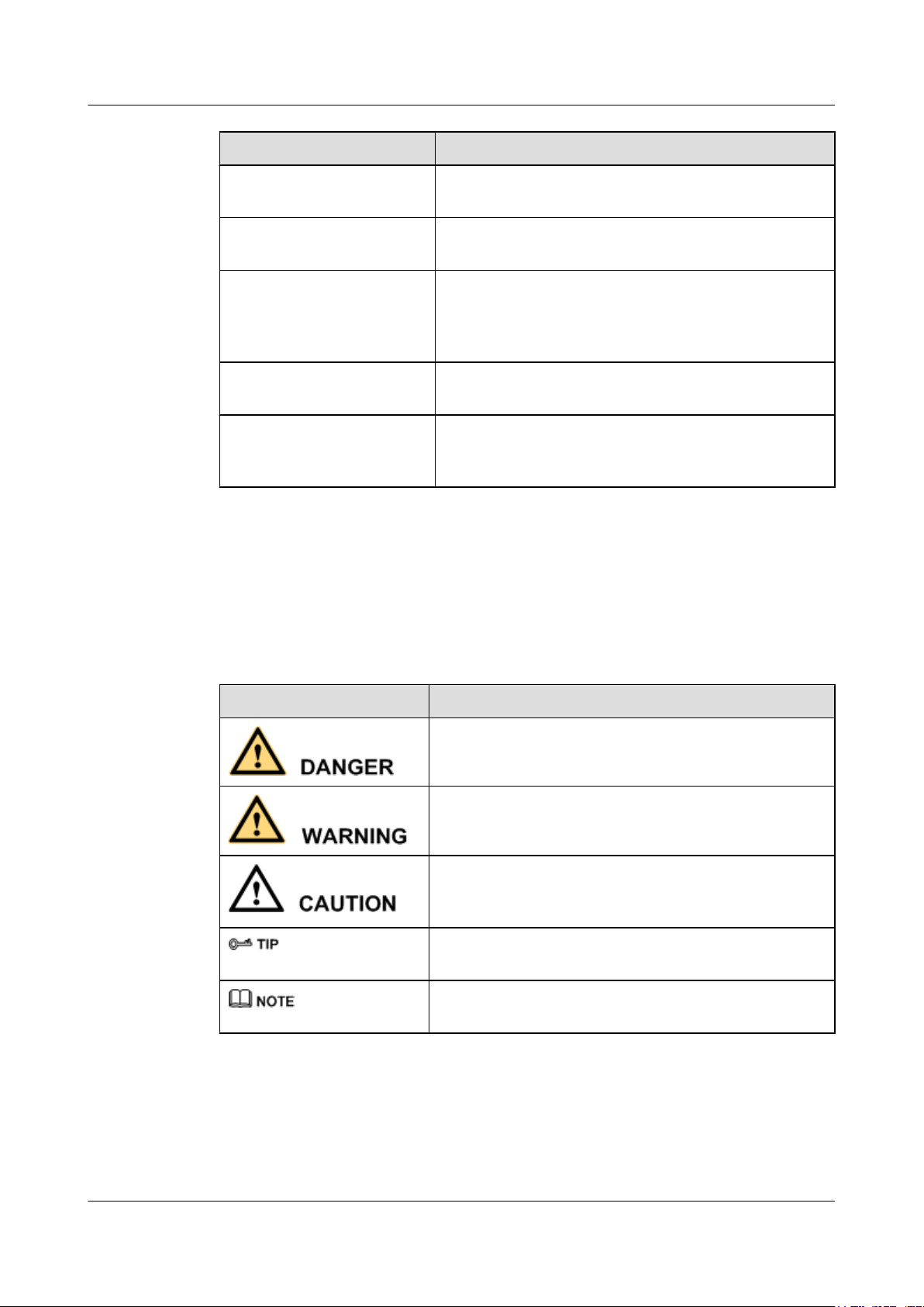
Figure 2-1 Appearance of the HG8240
Figure 2-2 Appearance of the HG8245
Issue 04 (2011-01-12) Huawei Proprietary and Confidential
Copyright © Huawei Technologies Co., Ltd.
2-3
Page 26
2 System Overview
EchoLife HG8240/HG8245/HG8247 GPON Terminal
Service Manual
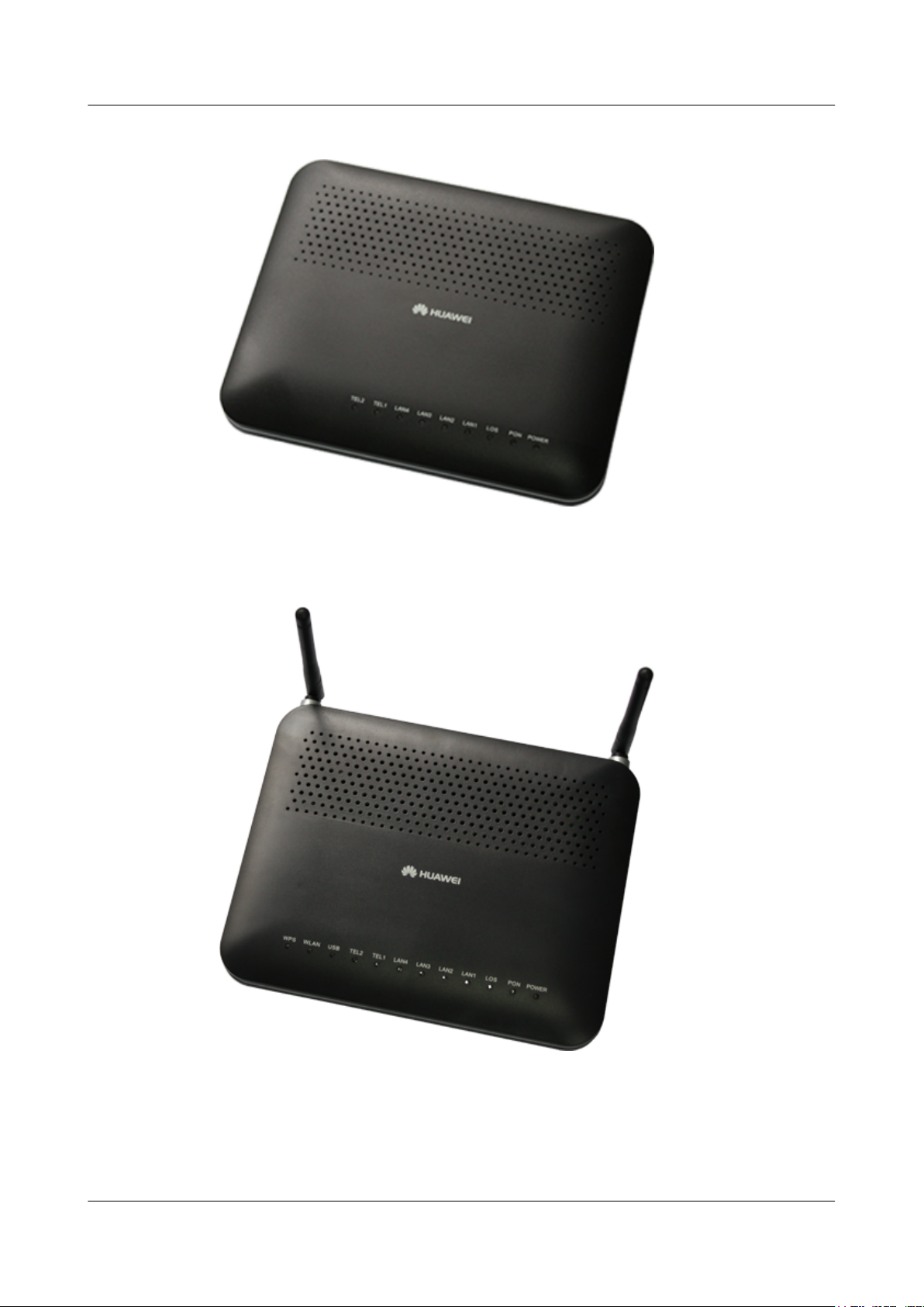
Figure 2-3 Appearance of the HG8247
2.1.2 Ports
This topic provides the appearance of the ports on the HG8240/HG8245/HG8247 and describes
the functions of the ports.
Ports on the HG8240
Figure 2-4 and Figure 2-5 show the ports on the rear panel and side panel of the HG8240
respectively.
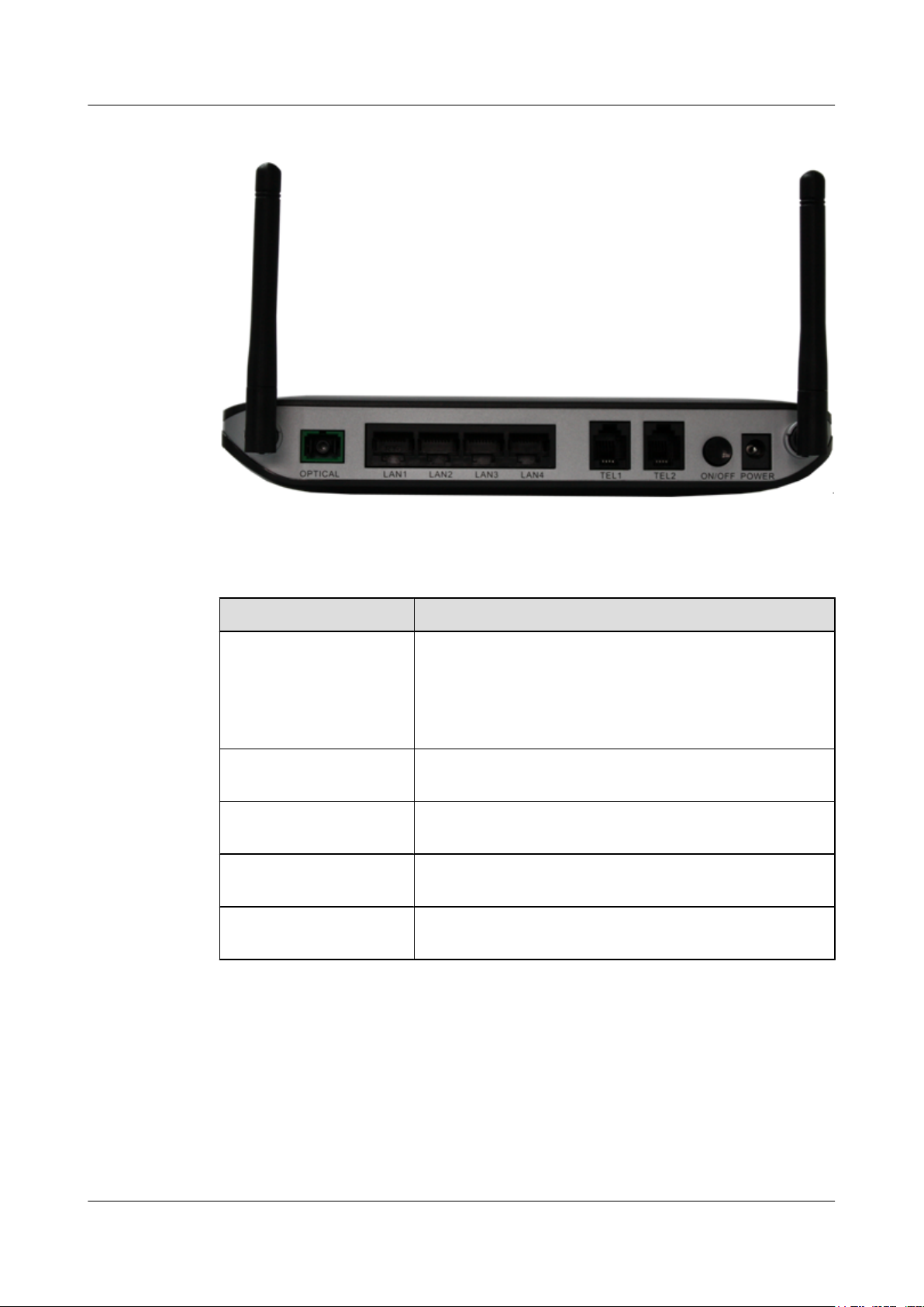
Figure 2-4 Ports on the rear panel of the HG8240
2-4 Huawei Proprietary and Confidential
Copyright © Huawei Technologies Co., Ltd.
Issue 04 (2011-01-12)
Page 27
EchoLife HG8240/HG8245/HG8247 GPON Terminal
Service Manual 2 System Overview
Table 2-1 Descriptions of the ports on the rear panel of the HG8240
Port and Button Function
Indicates the optical port. The optical port is equipped with a
rubber plug and is connected to an optical fiber for upstream
OPTICAL
transmission.
The type of the optical connector connected to the OPTICAL
port is SC/APC.
LAN1-LAN4
TEL1-TEL2
ON/OFF
POWER
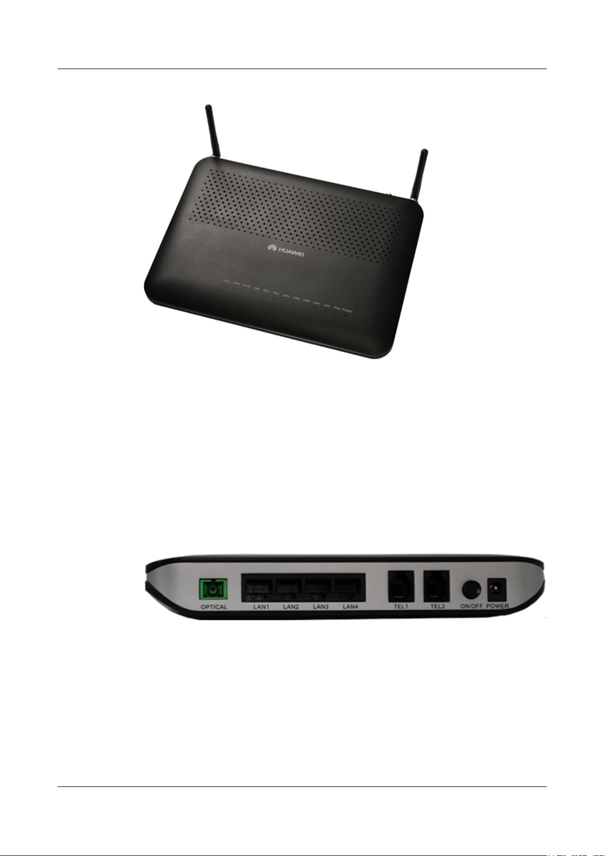
Figure 2-5 Ports on the side panel of the HG8240
Indicate auto-sensing 10/100/1000M Base-T Ethernet ports
(RJ-45), used for connecting to PCs or IP set-top boxes (STBs).
Indicate VoIP telephone ports (RJ-11), used for connecting to
the ports on telephone sets.
Indicates the power-on/power-off button, used for powering on
or powering off the device.
Indicates the power port, used for connecting to the power
adapter or backup battery.
Table 2-2 Descriptions of the ports on the side panel of the HG8240
Port and Button Function
BBU
RESET
Indicates the external backup battery monitoring port, used for
connecting to the backup battery for monitoring the battery.
Indicates the reset button. Press the button for a short time to
reset the device; press the button for a long time (longer than
10s) to restore the device to the default settings and reset the
device.
Ports on the HG8245
Figure 2-6 and Figure 2-7 show the ports on the rear panel and side panel of the HG8245
respectively.
Issue 04 (2011-01-12) Huawei Proprietary and Confidential
Copyright © Huawei Technologies Co., Ltd.
2-5
Page 28
2 System Overview
EchoLife HG8240/HG8245/HG8247 GPON Terminal
Service Manual
Figure 2-6 Ports on the rear panel of the HG8245
Table 2-3 Descriptions of the ports on the rear panel of the HG8245
Port and Button Function
Indicates the optical port. The optical port is equipped with a
rubber plug and is connected to an optical fiber for upstream
OPTICAL
transmission.
The type of the optical connector connected to the OPTICAL
port is SC/APC.
LAN1-LAN4
TEL1-TEL2
ON/OFF
POWER
Indicate auto-sensing 10/100/1000M Base-T Ethernet ports
(RJ-45), used for connecting to PCs or IP STBs.
Indicate VoIP telephone ports (RJ-11), used for connecting to
the ports on telephone sets.
Indicates the power-on/power-off button, used for powering on
or powering off the device.
Indicates the power port, used for connecting to the power
adapter or backup battery.
2-6 Huawei Proprietary and Confidential
Copyright © Huawei Technologies Co., Ltd.
Issue 04 (2011-01-12)
Page 29
EchoLife HG8240/HG8245/HG8247 GPON Terminal
Service Manual 2 System Overview
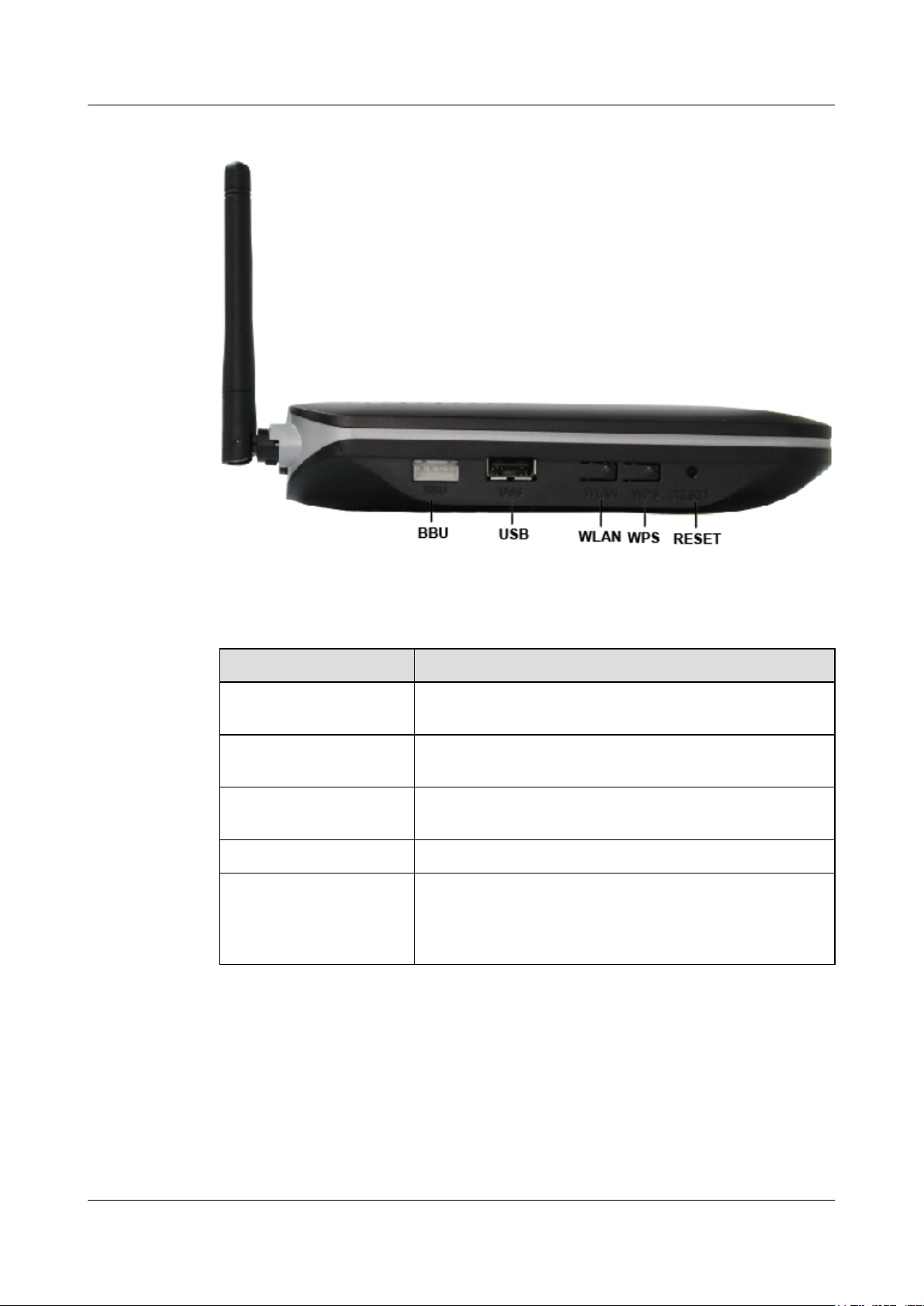
Figure 2-7 Ports on the side panel of the HG8245
Table 2-4 Descriptions of the ports on the side panel of the HG8245
Port and Button Function
BBU
USB
WLAN
WPS Indicates the WLAN data encryption switch.
RESET
Ports on the HG8247
Indicates the external backup battery monitoring port, used for
connecting to the backup battery for monitoring the battery.
Indicates the USB host port, used for connecting to a USB
storage device.
Indicates the WLAN button, used for enabling or disabling the
WLAN function.
Indicates the reset button. Press the button for a short time to
reset the device; press the button for a long time (longer than
10s) to restore the device to the default settings and reset the
device.
Figure 2-8 and Figure 2-9 show the ports on the rear panel and side panel of the HG8247
respectively.
Issue 04 (2011-01-12) Huawei Proprietary and Confidential
Copyright © Huawei Technologies Co., Ltd.
2-7
Page 30
2 System Overview
EchoLife HG8240/HG8245/HG8247 GPON Terminal
Service Manual
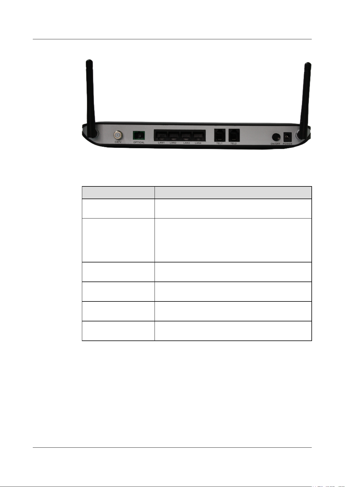
Figure 2-8 Ports on the rear panel of the HG8247
Table 2-5 Descriptions of the ports on the rear panel of the HG8247
Port and Button Function
CATV
OPTICAL
LAN1-LAN4
TEL1-TEL2
ON/OFF
POWER
Indicates the radio frequency (RF) port, used for connecting to
a TV set.
Indicates the optical port. The optical port is equipped with a
rubber plug and is connected to an optical fiber for upstream
transmission.
The type of the optical connector connected to the OPTICAL
port is SC/APC.
Indicate auto-sensing 10/100/1000M Base-T Ethernet ports
(RJ-45), used for connecting to PCs or IP STBs.
Indicate VoIP telephone ports (RJ-11), used for connecting to
the ports on telephone sets.
Indicates the power-on/power-off button, used for powering on
or powering off the device.
Indicates the power port, used for connecting to the power
adapter or backup battery.
2-8 Huawei Proprietary and Confidential
Copyright © Huawei Technologies Co., Ltd.
Issue 04 (2011-01-12)
Page 31

EchoLife HG8240/HG8245/HG8247 GPON Terminal
Service Manual 2 System Overview
Figure 2-9 Ports on the side panel of the HG8247
Table 2-6 Descriptions of the ports on the side panel of the HG8247
Port and Button Function
BBU
USB
WLAN
WPS Indicates the WLAN data encryption switch.
RESET
Indicates the external backup battery monitoring port, used for
connecting to the backup battery for monitoring the battery.
Indicate the USB host port, used for connecting to a USB
storage device.
Indicates the WLAN button, used for enabling or disabling the
WLAN function.
Indicates the reset button. Press the button for a short time to
reset the device; press the button for a long time (longer than
10s) to restore the device to the default settings and reset the
device.
2.1.3 LEDs
This topic provides the appearance of the LEDs on the HG8240/HG8245/HG8247 and describes
the indications of these LEDs.
Figure 2-10, Figure 2-11 and Figure 2-12 show the LEDs on the HG8240, HG8245 and
HG8247 respectively.
Issue 04 (2011-01-12) Huawei Proprietary and Confidential
Copyright © Huawei Technologies Co., Ltd.
2-9
Page 32

2 System Overview
EchoLife HG8240/HG8245/HG8247 GPON Terminal
Service Manual
Figure 2-10 LEDs on the HG8240
2-10 Huawei Proprietary and Confidential
Copyright © Huawei Technologies Co., Ltd.
Issue 04 (2011-01-12)
Page 33

EchoLife HG8240/HG8245/HG8247 GPON Terminal
Service Manual 2 System Overview
Figure 2-11 LEDs on the HG8245
Figure 2-12 LEDs on the HG8247
Issue 04 (2011-01-12) Huawei Proprietary and Confidential
Copyright © Huawei Technologies Co., Ltd.
2-11
Page 34

2 System Overview
EchoLife HG8240/HG8245/HG8247 GPON Terminal
Service Manual
Table 2-7 Indications of the LEDs on the HG8240/HG8245/HG8247
Silk Screen Name Status Indication
Green: always on The device is powered on.
POWER
PON
LOS
LAN1-LAN4
TEL1-TEL2
Power supply
LED
Authentication
LED
Connection
LED
Ethernet port
LED
Voice telephone
port LED
Orange: always
on
The device is powered by the
backup battery.
Off The power supply is cut off.
See Table 2-8.
See Table 2-8.
Always on
Blinks
Off
Always on
Blinks quickly
(twice per
second)
Blinks slowly
(once two
seconds)
The Ethernet connection is in the
normal state.
Data is being transmitted on the
Ethernet port.
The Ethernet connection is not set
up.
The connection to the voice server
is set up.
The connection to the voice server
is set up and the telephone is in the
off-hook or ringing state.
The ONT is registering with the
voice server.
Off
Always on
USB USB port LED
Blinks quickly
(twice per
second)
Off
Always on The WLAN function is enabled.
WLAN
2-12 Huawei Proprietary and Confidential
WLAN port
LED
Copyright © Huawei Technologies Co., Ltd.
Blinks
The connection to the voice server
is not set up.
The USB port is connected and is
working in the host mode, but no
data is being transmitted.
Data is being transmitted on the
USB port.
The system is not powered on or the
USB port is not connected.
Data is being transmitted on the
WLAN port.
Issue 04 (2011-01-12)
Page 35

EchoLife HG8240/HG8245/HG8247 GPON Terminal
Service Manual 2 System Overview
Silk Screen Name Status Indication
Off The WLAN function is disabled.
Always on The WPS function is enabled.
WPS WPS port LED
CATV CATV port LED
Table 2-8 Indications of PON and LOS LEDs
LED Status
No.
PON LOS
1 Off Off The ONT is disabled by the OLT.
2 Blinks quickly
(twice per
second)
3 Always on Off
Blinks
Off The WPS function is disabled.
Always on
Off
Off The ONT is attempting to set up a
A Wi-Fi terminal is accessing the
system.
The CATV function is enabled and
CATV signals are received.
The CATV function is disabled or
CATV signals are not received.
Indication
connection to the OLT.
The connection between the ONT
and the OLT is set up.
4 Off Blinks slowly
(once two
seconds)
Blinks quickly
5
(twice per
second)
Blinks quickly
(twice per
second)
2.2 Typical Network Applications
This topic describes the typical network applications of the HG8240/HG8245/HG8247.
As a network terminal, the HG8240/HG8245/HG8247 is deployed at the GPON access layer
and connects home users and SOHO users to the Internet through optical upstream ports. On the
local area network (LAN) side, the HG8240/HG8245/HG8247 provides abundant hardware
ports to meet various network requirements of home users and SOHO users.
Network Topology of the HG8240
Figure 2-13 shows the position of the HG8240 in a network.
The Rx optical power of the ONT is
lower than the optical receiver
sensitivity.
The OLT detects that the ONT is a
rogue ONT.
Issue 04 (2011-01-12) Huawei Proprietary and Confidential
Copyright © Huawei Technologies Co., Ltd.
2-13
Page 36

2 System Overview
EchoLife HG8240/HG8245/HG8247 GPON Terminal
Service Manual
Figure 2-13 Network topology of the HG8240
l In the upstream direction, the HG8240 is connected to the optical splitter and the network-
side OLT through the passive optical network (PON) port, namely the OPTICAL port, to
provide integrated access services.
l In the downstream direction, the HG8240 is connected to various terminals through the
following LAN-side ports to implement the triple play service:
– Four 10/100/1000M Base-T Ethernet ports, which can be connected to terminals such
as PCs, STBs, and video phoned to provide the high-speed data and video services.
– Two TEL ports, which can be connected to telephone sets or fax machines to provide
superior and cost-effective voice over IP (VoIP), fax over IP (FoIP), and modem over
IP (MoIP) services.
Network Topology of the HG8245
Figure 2-14 shows the position of the HG8245 in a network.
Figure 2-14 Network topology of the HG8245
2-14 Huawei Proprietary and Confidential
Copyright © Huawei Technologies Co., Ltd.
Issue 04 (2011-01-12)
Page 37

EchoLife HG8240/HG8245/HG8247 GPON Terminal
Service Manual 2 System Overview
l In the upstream direction, the HG8245 is connected to the optical splitter and the network-
side OLT through the PON port, namely the OPTICAL port, to provide integrated access
services.
l In the downstream direction, the HG8245 is connected to various terminals through the
following LAN-side ports to implement the triple play service:
– Four 10/100/1000M Base-T Ethernet ports, which can be connected to terminals such
as PCs, STBs, and video phones to provide the high-speed data and video services.
– Two TEL ports, which can be connected to telephone sets or fax machines to provide
superior and cost-effective VoIP, FoIP, and MoIP services.
– Two Wi-Fi antennas, which can connect to Wi-Fi terminals wirelessly to provide a
secure and reliable high-speed wireless network.
– One USB port, which can be connected to a USB storage device to provide convenient
storage and file sharing services within a home network.
Network Topology of the HG8247
Figure 2-15 shows the position of the HG8247 in a network.
Figure 2-15 Network topology of the HG8247
l In the upstream direction, the HG8247 is connected to the optical splitter and the network-
side OLT through the PON port, namely the OPTICAL port, to provide integrated access
services.
l In the downstream direction, the HG8247 is connected to various terminals through the
following LAN-side ports to implement the triple play service:
– One CATV port, which can be connected to a TV set to provide high-quality CATV
service transmission.
– Four 10/100/1000M Base-T Ethernet ports, which can be connected to terminals such
as PCs, STBs, and video phones to provide the high-speed data and video services.
– Two TEL ports, which can be connected to telephone sets or fax machines to provide
superior and cost-effective VoIP, FoIP, and MoIP services.
Issue 04 (2011-01-12) Huawei Proprietary and Confidential
Copyright © Huawei Technologies Co., Ltd.
2-15
Page 38

2 System Overview
EchoLife HG8240/HG8245/HG8247 GPON Terminal
Service Manual
– Two Wi-Fi antennas, which can connect to Wi-Fi terminals wirelessly to provide a
secure and reliable high-speed wireless network.
– One USB port, which can be connected to a USB storage device to provide convenient
storage and file sharing services within a home network.
2-16 Huawei Proprietary and Confidential
Copyright © Huawei Technologies Co., Ltd.
Issue 04 (2011-01-12)
Page 39

EchoLife HG8240/HG8245/HG8247 GPON Terminal
Service Manual 3 Configuration
3 Configuration
About This Chapter
This topic describes how to configure services through the NMS, the OLT CLI, the Web page
or the U2560.
Context
NOTE
l The procedures for configuring HG8240/HG8245/HG8247 are similar. The following sections
consider HG8245 as an example.
l The U2000 V100R002C01 is used in the following configuration examples. The screen snapshots vary
with different U2000 versions but the configuration procedures are similar. For details, see the
associated configuration manual.
l Currently, only the U2560 can function as the TR-069 server. This manual uses the U2560 as an
example to perform the TR-069 operations.
3.1 Before Your Start
This section provides common methods for configuring ONT services.
3.2 Configuring the Service by Using the NMS
This topic describes how to configure Internet access service, VoIP service and IPTV service
by using the NMS.
3.3 Configuration by Using OLT Commands
This topic describes how to configure the Internet access service, VoIP service and IPTV service
by using OLT commands.
3.4 Configuration on the Web Page
This topic describes how to configure Internet access service, VoIP service and Wi-Fi service
on the Web page.
3.5 Configuring the Service by Using U2560
This topic describes how to configure the Internet access service, VoIP service and Wi-Fi service
by using U2560.
3.6 Operation Guide on the XML Configuration File
This topic describes how to issue the XML configuration files on the Web page and on the
U2000.
Issue 04 (2011-01-12) Huawei Proprietary and Confidential
Copyright © Huawei Technologies Co., Ltd.
3-1
Page 40

3 Configuration
3.1 Before Your Start
This section provides common methods for configuring ONT services.
Methods for configuring ONT services include configuring services by using the OLT
commands, U2000, Web interface, TR-069 server and by issuing XML configuration file. Table
3-1 shows the application scenario of each configuration method.
Table 3-1 Application scenario of each configuration method
EchoLife HG8240/HG8245/HG8247 GPON Terminal
Service Manual
Configurati
on Method
OLT
commands
U2000 This method can be used to configure Layer 2 services for the ONT by using
Web
interface
TR-069
server
Application Scenario
This method uses the OMCI protocol to configure ONT services. It can be
used to add ONTs, configure ONT port attributes and port VLANs, and to
enable the Layer 2 service channels between the OLT and ONTs. It can
implement all configurations for Layer 2 services such as the Layer 2 Internet
access service and the Layer 2 multicast service. In the case of configuring
Layer 3 services such as the WAN port, ONT voice service, and Wi-Fi
service, coordination of one or more other methods is required.
the OMCI protocol, and to configure ONT value-added service profile and
customized parameters. Customized parameters can be configured after batch
adding general configurations to facilitate configuration efficiency. This
method is recommended in batch service provisionings.
This method uses Web interface of the ONT to configure related ONT
parameters. In this method, batch configuration is not supported, and the
coordination of OLT commands or the U2000 is required. It is simple and is
generally used in the deployment.
All the configurable nodes of the ONT are defined on the TR-069 server. The
TR-069 server supports real-time configuration and status query. In this
method, the coordination of OLT commands or the U2000 is required.
Issuing XML
configuration
file
Table 3-2 lists configuration methods supported in the FTTH service.
3-2 Huawei Proprietary and Confidential
The ONT voice service and gateway involve a large amount of configuration
information, most of which is not defined in the OMCI protocol and cannot
be configured on Web interface or the U2000. This method functions as a
supplement to Web interface and the U2000. In this method, the coordination
of OLT commands or the U2000 is required. This method is not recommended
because it is complex.
Copyright © Huawei Technologies Co., Ltd.
Issue 04 (2011-01-12)
Page 41

EchoLife HG8240/HG8245/HG8247 GPON Terminal
Service Manual 3 Configuration
Table 3-2 Configuration methods supported in the FTTH service
Service
Type
Layer 2
Internet
access
service
Layer 3
Internet
access
service
Layer 2
multicast
service
Layer 3
bridge
multicast
service
Configurat
ion by
Using OLT
Commands
Configurat
ion by
Using the
U2000
Configurat
ion by
Using Web
Interface
Supported Supported Configuratio
n is not
needed.
Coordinatio
n of other
methods is
required.
Supported Coordinatio
n of OLT
commands
or the U2000
is required.
Supported Supported Configuratio
n is not
needed.
Coordinatio
n of other
methods is
required.
Supported Coordinatio
n of OLT
commands
or the U2000
is required.
Configurat
ion by
Using
TR-069
Server
Configuratio
n not needed.
Coordinatio
n of OLT
commands
or the U2000
is required.
Configuratio
n is not
needed.
Coordinatio
n of OLT
commands
or the U2000
is required.
Configurat
ion by
Issuing
XML
Configurat
ion File
Configuratio
n not needed
Coordinatio
n of OLT
commands
or the U2000
is required.
Configuratio
n is not
needed.
Coordinatio
n of OLT
commands
or the U2000
is required.
Voice
service
Wi-Fi
service
Coordinatio
n of other
methods is
required.
Not
supported
Supported Coordinatio
n of OLT
commands
or the U2000
is required.
Not
Supported Supported Supported
supported
Coordinatio
n of OLT
commands
or the U2000
is required.
Coordinatio
n of OLT
commands
or the U2000
is required.
NOTE
Currently, the HG8240/HG8245/HG8247 supports only the U2560 as the TR-069 server. Therefore, the TR-069
configuration in this chapter is the U2560 configuration.
The following section provides key technologies involved in these methods:
l ONT management and control interface (OMCI) is a protocol defined in ITU-T G.984.4.
OMCI defines the format and mechanism of the interactive messages between the GPON
OLT and ONTs. It analyzes the service model of ONT services and defines a series of
management entities used for the service description.
OMCI defines the format of the message exchanged between the GPON OLT and ONTs
and the message acknowledgment and retransmission mechanism. In this way, the OMCI
provides a logical channel for communication. Operators can manage and configure ONTs
(including port attribute and port VLAN) using OLT commands or the U2000. In addition,
OMCI supports configuring an ONT offline and restoring the ONT configuration after the
Issue 04 (2011-01-12) Huawei Proprietary and Confidential
Copyright © Huawei Technologies Co., Ltd.
3-3
Page 42

3 Configuration
EchoLife HG8240/HG8245/HG8247 GPON Terminal
Service Manual
ONU goes online. With this management mechanism, ONTs do not need to save their own
configuration information. This facilitates service provisioning and ONT maintenance. The
OMCI configuration mainly indicates the Layer 2 service configuration such as the Layer
2 Internet access service and the Layer 2 multicast service.
l TR-069 is a WAN management protocol for CPEs. It implements automatic configuration
on ONTs by using auto-negotiation interactive protocol between the application control
server (ACS) and the CPE. The TR-069 protocol supports the following management
functions:
– Automatic configuration and dynamic service provision
– Software and firmware mapping management
– Status and performance monitoring
– Fault diagnosis
l The extensible markup language (XML) file can be configured in the following two ways:
– Issuing XML configurations by using Web interface: Web interface stores the
configuration information about the ONT in an XML configuration file, and imports
the file for the ONT; then the ONT parses the configuration information in the file for
processing and storing.
– Issuing XML configurations by using the U2000: The U2000 stores the configuration
information about the ONT in an XML configuration file, and transfers the file to the
OLT by using FTP; then the OLT further transfers the file to the ONT by using the
OMCI protocol; after receiving the file, the ONT parses the configuration information
in the file for processing and storing.
CAUTION
l Web interface and the U2000 cannot use the same XML configuration file. The XML
configuration file of Web interface contains all configuration data, while the XML
configuration file of the U2000 contains only part of the configuration data.
l H.248 and SIP can share the same XML configuration file, but the configurations
involving voice service need to be re-configured accordingly.
l The XML configuration file is generally exported for modifying, and then imported
back. Configuration rolls back or even factory defaults are restored if an incorrect XML
configuration file is imported. When configuration parameters of an XML configuration
file need to be modified, please contact Huawei technical engineers for help.
3.2 Configuring the Service by Using the NMS
This topic describes how to configure Internet access service, VoIP service and IPTV service
by using the NMS.
3.2.1 Data Plan
This topic provides the data plan for the configuration examples of the GPON FTTH services.
You can configure the services according to the data plan.
3.2.2 Configuring GPON FTTH Layer 2 Internet Access Service on the NMS
This topic describes how to configure the high-speed Internet service when an ONT is connected
to an OLT through a GPON port.
3-4 Huawei Proprietary and Confidential
Copyright © Huawei Technologies Co., Ltd.
Issue 04 (2011-01-12)
Page 43

EchoLife HG8240/HG8245/HG8247 GPON Terminal
Service Manual 3 Configuration
3.2.3 Configuring GPON FTTH Layer 3 Internet Access Service on the NMS
This topic describes how to configure the high-speed Internet service when an ONT is connected
to an OLT through a GPON port.
3.2.4 Configuring GPON FTTH Voice Service (H.248) on the NMS
This topic describes how to configure the voice service when an ONT is connected to an OLT
through a GPON port.
3.2.5 Configuring GPON FTTH Voice Service (SIP) on the NMS
This topic describes how to configure the voice service when an ONT is connected to an OLT
through a GPON port.
3.2.6 Configuring GPON FTTH Layer 2 Multicast Service on the NMS
This topic describes how to configure the multicast service when an ONT is connected to an
OLT through a GPON port.
3.2.7 Configuring GPON FTTH Layer 3 Bridge Multicast Service on the NMS
This topic describes how to configure the multicast service when an ONT is connected to an
OLT through a GPON port.
3.2.1 Data Plan
Data Plan
This topic provides the data plan for the configuration examples of the GPON FTTH services.
You can configure the services according to the data plan.
Table 3-3 Data plan for the GPON FTTH services
Service
Type
Device
managemen
t
Item Settings Remarks
Upstream port of an
OLT
GPON port of the
OLT
ONT
0/19/0 -
0/2/1 -
l SN: 6877687714852901
l Name: ONT
l ONU Type: ONT
l ONU ID: 0
l Authentication Mode: SN
l Terminal Type: 245
l Software Version:
V1R002C00 or
V1R002C01
-
MEF IP traffic
profile
Issue 04 (2011-01-12) Huawei Proprietary and Confidential
Copyright © Huawei Technologies Co., Ltd.
l Name: FTTx
l CIR: 20480
l Outer Priority: 1
The MEF IP traffic
profile is used on the
ONT to control
upstream and
downstream traffic.
3-5
Page 44

3 Configuration
EchoLife HG8240/HG8245/HG8247 GPON Terminal
Service Manual
Service
Type
Item Settings Remarks
DBA profile
l Name: FTTx
-
l T-CONT type: Maximum
Bandwidth
l Maximum Bandwidth:
32768
Line profile
l Name: FTTx
-
l Mapping Mode: VLAN
l Qos Mode: Priority Queue
l T-CONT Index: 1
l DBA Profile: FTTx
l GEM Port Index: 1
l Priority Queue:1
Service profile
l Name: FTTx
-
l Number of Pots Ports: 2
l Number of ETH Ports: 4
l Vlan Type: Translation
l C-VLAN: 100,1000
l S-VLAN: 100,1000
Internet
service
VLAN
Service port
l VLAN ID: 100
l Type: Smart VLAN
l Name: HSI
l VLAN ID: 100
l Interface Selection:
0/2/1/0/0
l Service Type: Multi-
Service VLAN
l User VLAN: 10
l Keep the upstream and
downstream settings the
same: selected
l Upstream Traffic Name:
FTTx
-
-
3-6 Huawei Proprietary and Confidential
Copyright © Huawei Technologies Co., Ltd.
Issue 04 (2011-01-12)
Page 45

EchoLife HG8240/HG8245/HG8247 GPON Terminal
Service Manual 3 Configuration
Service
Type
Item Settings Remarks
ONT value-added
services (Layer 3
l Profile Name: ONT-HSI
l Vendor ID: HWTC(2011)
-
routing)
l Terminal Type: 245
l Version: V1R002C00–
V1R002C01
l WAN VLAN ID: 10
l Service Type: INTERNET
l Connection Type:
IP_Routed
l Addressing Type: PPPoE
(User Name:
iadtest@pppoe, Password:
iadtest)
l Priority: 1
l NAT function: enable
l Bound port: LAN1 (LAN1
is a Layer 3 LAN)
IPTV
service
VLAN
Service port
Multicast VLAN
l VLAN ID: 1000
l Type: Smart VLAN
l Name: IGMP
l Vlan ID: 1000
l Interface Selection:
0/2/1/0/0
l Service Type: Multi-
Service VLAN
l User VLAN: 30
l Keep the upstream and
downstream settings the
same: selected
l Upstream Traffic Name:
FTTx
l IGMP Version: IGMP V3
l Work Mode: igmp_proxy
l VLAN ID: 1000
-
-
-
Issue 04 (2011-01-12) Huawei Proprietary and Confidential
Copyright © Huawei Technologies Co., Ltd.
3-7
Page 46

3 Configuration
EchoLife HG8240/HG8245/HG8247 GPON Terminal
Service Manual
Service
Item Settings Remarks
Type
Program profile
Multicast user
ONT value-added
services (Layer 3
bridge)
l Name: program1
l Start IP Address: 224.0.1.1
l End IP Address: 224.0.1.1
l Source IP Address:
10.10.10.20
l Preview Profile: 0 (the
default value)
l Alias: IGMPUserA
l Unlimited Band Width:
selected
l Select Service Port: service
virtual port named IGMP
l Profile Name: ONT-HSI
l Vendor ID: HWTC(2011)
l Terminal Type: 245
l Version: V1R002C00–
V1R002C01
l WAN VLAN ID: 30
l Priority: 4
l Service Type: INTERNET
l Connection Type:
IP_Bridged
l Bound port: LAN3 (LAN3
is a Layer 3 LAN)
-
-
-
VoIP
service
VLAN
Service port
l VLAN ID: 200
l Type: Smart VLAN
l Name: VOIP
l Vlan ID: 200
l Interface Selection:
0/2/1/0/0
l Service Type: Multi-
Service VLAN
l User VLAN: 20
l Keep the upstream and
downstream settings the
same: selected
l Upstream Traffic Name:
FTTx
3-8 Huawei Proprietary and Confidential
Copyright © Huawei Technologies Co., Ltd.
-
-
Issue 04 (2011-01-12)
Page 47

EchoLife HG8240/HG8245/HG8247 GPON Terminal
Service Manual 3 Configuration
Service
Type
Item Settings Remarks
ONT value-added
services (H.248)
l Profile Name: ONT-VoIP
l Vendor ID: HWTC(2011)
The software
version that supports
H.248 is
l Terminal Type: 245
V100R002C00.
l Version: V1R002C00–
V1R002C01
l WAN VLAN ID: 20
l Service Type: VoIP
l Connection Type:
IP_Routed
l Priority: 6
l Signaling Protocol: H248
l Primary MGC:
200.200.200.200
l MID Format: Domain name
l MGC Port: 2944
l MGC Domain name:
6877687714852901
l TID: A0 and A1
Issue 04 (2011-01-12) Huawei Proprietary and Confidential
Copyright © Huawei Technologies Co., Ltd.
3-9
Page 48

3 Configuration
EchoLife HG8240/HG8245/HG8247 GPON Terminal
Service Manual
Service
Type
Item Settings Remarks
ONT value-added
services (SIP)
l Profile Name: ONT-VoIP
l Vendor ID: HWTC(2011)
l Terminal Type: 245
l Version: V1R002C00–
V1R002C01
l WAN VLAN ID: 20
l Service Type: VoIP
l Connection Type:
IP_Routed
l Priority: 6
l Signaling Protocol: SIP
l Proxy Server:
200.200.200.200
l SIP Server Port: 5060
l Home Domain:
softx3000.huawei.com
l Digitmap: x.S|x.# (Default)
l User 1:
– Directory Number:
88001234
– Auth User Name:
88001234@softx3000.
huawei.com
– Auth Password: iadtest1
l User 2:
– Directory Number:
88001235
– Auth User Name:
88001235softx3000.hu
awei.com
– Auth Password: iadtest2
The software
version that supports
SIP is
V100R002C01.
3.2.2 Configuring GPON FTTH Layer 2 Internet Access Service on the NMS
This topic describes how to configure the high-speed Internet service when an ONT is connected
to an OLT through a GPON port.
Context
For details of the data plan, see Data Plan.
3-10 Huawei Proprietary and Confidential
Copyright © Huawei Technologies Co., Ltd.
Issue 04 (2011-01-12)
Page 49

OLT
ONT
PC
BRAS
LAN Switch
Optical splitter
U2000
EchoLife HG8240/HG8245/HG8247 GPON Terminal
Service Manual 3 Configuration
Example Network
l The PC gains access to the Internet in PPPoE dialup mode.
l The ONT is connected to the GPBC card of the OLT through an optical fiber.
l The broadband remote access server (BRAS) provides the authentication, authorization,
and accounting (AAA) functions.
Figure 3-1 Configuring the GPON FTTH Internet service
Procedure
l Add the ONT to the U2000 in profile mode.
1. Configure an MEF IP traffic profile.
(1) Choose Configuration > Access Profile Management > Traffic Profile from
Issue 04 (2011-01-12) Huawei Proprietary and Confidential
the main menu.
(2) Click the MEF IP Traffic Profile tab.
(3) Right-click and choose Add Global Profile from the shortcut menu.
Copyright © Huawei Technologies Co., Ltd.
3-11
Page 50

3 Configuration
EchoLife HG8240/HG8245/HG8247 GPON Terminal
Service Manual
(4) In the dialog box that is displayed, set the parameters.
– Name: FTTx
– CIR: 20480
– Outer Priority: 1
(5) Click OK.
(6) In the information list, right-click the record and choose Download to NE from
the shortcut menu.
(7) In the dialog box that is displayed, select the required NE(s), and click OK.
2. Configure a DBA profile.
(1) Choose Configuration > Access Profile Management > GPON Profile from
the main menu.
(2) Click the DBA Profile tab.
(3) Right-click and choose Add Global Profile from the shortcut menu.
(4) In the dialog box that is displayed, set the parameters.
– Name: FTTx
– T-CONT type: Maximum Bandwidth
– Maximum Bandwidth: 32768
3-12 Huawei Proprietary and Confidential
Copyright © Huawei Technologies Co., Ltd.
Issue 04 (2011-01-12)
Page 51

EchoLife HG8240/HG8245/HG8247 GPON Terminal
Service Manual 3 Configuration
(5) Click OK.
(6) In the information list, right-click the record and choose Download to NE from
the shortcut menu.
(7) In the dialog box that is displayed, select the required NE(s), and click OK.
3. Configure a line profile.
In a line profile, a GEM port can be bound to up to eight service streams. In a GEM
port, different GEM connections need to be set up for different service streams.
In this example, the mapping between GEM ports and MDU-side services is
implemented through VLANs, and the service streams of each service are mapped to
GEM port 1. In addition, different GEM connections are set up for the management
VLAN and the VLANs for the Internet, voice, and multicast services.
(1) Choose Configuration > Access Profile Management > GPON Profile from
the main menu.
(2) Click the Line Profile tab.
(3) Right-click and choose Add Global Profile from the shortcut menu.
(4) In the dialog box that is displayed, set the parameters.
– Set Name to FTTx.
– Choose Base Info. from the navigation tree and set the parameters.
– Mapping Mode: VLAN
– Qos Mode: Priority Queue
Issue 04 (2011-01-12) Huawei Proprietary and Confidential
Copyright © Huawei Technologies Co., Ltd.
3-13
Page 52

3 Configuration
EchoLife HG8240/HG8245/HG8247 GPON Terminal
Service Manual
– Right-click T-CONT Info. in the navigation tree and choose ADD T-
CONT from the shortcut menu. In the dialog box that is displayed, set the
parameters.
– T-CONT Index: 1
– DBA Profile: FTTx
– Right-click T-CONT1 in the navigation tree and choose Add GEM Port
from the shortcut menu. In the dialog box that is displayed, set the parameters.
– GEM Port Index: 1
– Priority Queue: 1
3-14 Huawei Proprietary and Confidential
Copyright © Huawei Technologies Co., Ltd.
Issue 04 (2011-01-12)
Page 53

EchoLife HG8240/HG8245/HG8247 GPON Terminal
Service Manual 3 Configuration
– Right-click GEM Port1 in the navigation tree and choose Add GEM
Connection from the shortcut menu. In the dialog box that is displayed, set
the parameter.
– GEM Connection Index: 0 (this parameter is set to 0 automatically)
– VLAN ID: 10 (Internet access user-side VLAN ID)
– Right-click GEM Port1 in the navigation tree and choose Add GEM
Connection from the shortcut menu. In the dialog box that is displayed, set
the parameter.
– GEM Connection Index: 1 (this parameter is set to 1 automatically)
– VLAN ID: 20 (Voice user-side VLAN ID)
Issue 04 (2011-01-12) Huawei Proprietary and Confidential
Copyright © Huawei Technologies Co., Ltd.
3-15
Page 54

3 Configuration
EchoLife HG8240/HG8245/HG8247 GPON Terminal
Service Manual
– Right-click GEM Port1 in the navigation tree and choose Add GEM
Connection from the shortcut menu. In the dialog box that is displayed, set
the parameter.
– GEM Connection Index: 2 (this parameter is set to 2 automatically)
– VLAN ID: 30 (Multicast user-side VLAN ID)
(5) Click OK.
(6) In the information list, right-click the record and choose Download to NE from
the shortcut menu.
(7) In the dialog box that is displayed, select the required NE(s), and click OK.
4. Configure a service profile.
The service profile type should be consistent with the actual ONT type. The HG8240
and HG8245 each have four ETH ports and two POTS ports. The HG8247 has four
ETH ports, two POTS ports, and one CATV port.
(1) Choose Configuration > Access Profile Management > GPON Profile from
the main menu.
(2) Click the Service Profile tab.
3-16 Huawei Proprietary and Confidential
Copyright © Huawei Technologies Co., Ltd.
Issue 04 (2011-01-12)
Page 55

EchoLife HG8240/HG8245/HG8247 GPON Terminal
Service Manual 3 Configuration
(3) Right-click and choose Add Global Profile from the shortcut menu.
(4) In the dialog box that is displayed, set the parameters.
– Set Name to FTTx.
– Choose Base Info. from the navigation tree and set the parameters.
– Number of Pots Ports: 2
– Number of ETH Ports: 4
– Choose UNI Port from the navigation tree. In the window that is displayed,
right-click the record where Port Type is set to ETH and Port ID is set to
1, and choose UNI Port Configuration Properties from the shortcut menu.
In the dialog box that is displayed, set the parameters.
– In the dialog box that is displayed, right-click and choose Add, and
configure the parameters of VLAN switch.
– Service Type: Translation
– S-VLAN: 10 (Internet access user-side VLAN ID)
– C-VLAN: 10 (Internet access user-side VLAN ID)
– Choose UNI Port from the navigation tree. In the window that is displayed,
right-click the record where Port Type is set to ETH and Port ID is set to
3, and choose UNI Port Configuration Properties from the shortcut menu.
In the dialog box that is displayed, set the parameters.
Issue 04 (2011-01-12) Huawei Proprietary and Confidential
Copyright © Huawei Technologies Co., Ltd.
3-17
Page 56

3 Configuration
EchoLife HG8240/HG8245/HG8247 GPON Terminal
Service Manual
– In the dialog box that is displayed, right-click and choose Add, and
configure the parameters of VLAN switch.
– Service Type: Translation
– S-VLAN: 30 (Multicast user-side VLAN ID)
– C-VLAN: 30 (Multicast user-side VLAN ID)
(5) Click OK.
(6) In the information list, right-click the record and choose Download to NE from
the shortcut menu.
(7) In the dialog box that is displayed, select the required NE(s), and click OK.
5. Confirm the ONT.
(1) In the Main Topology, double-click the required OLT in the Physical Root
navigation tree; or right-click the required OLT and choose NE Explorer from
the shortcut menu.
(2) Choose GPON > GPON UNI Port from the navigation tree.
(3) On the GPON UNI Port tab page, set the filter criteria to display the required
GPON UNI ports.
(4) In the information list, right-click GPON UNI port 0/2/1 and choose Enable
ONU Auto Find from the shortcut menu.
(5) Click the Auto-Discovered ONU Info tab in the lower pane, right-click the ONU
with SN 32303131B39FD641, and then choose Confirm ONU from the shortcut
menu.
– Name: ONT
– ONU ID: 0
– ONU Type: ONT
– On the Basic Parameters tab page, set the parameters.
– Line Profile: FTTx (click
next to Line Profile and select the line profile
named FTTx in the dialog box that is displayed)
– Service Profile: FTTx (click
service profile named FTTx in the dialog box that is displayed)
– Authentication Mode: SN
– Terminal Type: 245
3-18 Huawei Proprietary and Confidential
Copyright © Huawei Technologies Co., Ltd.
next to Service Profile and select the
Issue 04 (2011-01-12)
Page 57

EchoLife HG8240/HG8245/HG8247 GPON Terminal
Service Manual 3 Configuration
– Software Version: V1R002C00 (or V1R002C01)
(6) Click OK.
l Configure the Internet service.
The prerequisite for performing operations in the navigation tree is to navigate to the NE
Explorer of the OLT. To navigate to the NE Explorer of the OLT, do as follows: In the
Main Topology, double-click the required OLT in the Physical Root navigation tree; or
right-click the required OLT and choose NE Explorer from the shortcut menu.
1. Configuring the Information About the ETH Port of a GPON ONU
(1) Choose GPON > GPON ONU from the navigation tree.
(2) On the GPON ONU tab page, set the filter criteria to display the required GPON
ONUs.
(3) In the information list, right-click the ONT record where Frame, Slot, Port, and
ONU ID are set to 0, 2, 1, and 0 respectively and click the The Ont's UNI Port
Info tab in the lower pane.
(4) On the The Ont's UNI Port Info tab page, right-click the record where UNI
Type is set to ETH and UNI ID is set to 1, and choose Modifyfrom the shortcut
menu.
(5) In the dialog box that is displayed, set Default VLAN ID to 10.
(6) Click OK.
2. Configure a service VLAN on the OLT side.
A service VLAN is the VLAN used for the Internet service.
(1) Choose VLAN from the navigation tree.
(2) On the VLAN tab page, right-click and choose Add from the shortcut menu.
(3) In the dialog box that is displayed, set the parameters.
– VLAN ID: 100
– Type: Smart VLAN
Issue 04 (2011-01-12) Huawei Proprietary and Confidential
Copyright © Huawei Technologies Co., Ltd.
3-19
Page 58

3 Configuration
EchoLife HG8240/HG8245/HG8247 GPON Terminal
Service Manual
(4) Click Next. Click the Upstream Port tab and add upstream port 0/19/0 as the
upstream port of the VLAN.
(5) Click Done.
3. Add a service virtual port on the OLT side.
(1) On the VLAN tab page, select the record where VLAN ID is set to 100 and click
the ServicePort tab in the lower pane.
(2) In the information list, right-click and choose Add from the shortcut menu.
(3) In the dialog box that is displayed, set the parameters.
– Name: HSI
– VLAN ID: 100 (SVLAN ID)
– Connection Type: LAN-GPON (when the physical port is a GPON port) or
LAN-EPON (when the physical port is an EPON port)
– Interface Selection: 0/2/1/0/0 (when the connection type is LAN-GPON) or
0/2/1/0 (when the connection type is LAN-EPON)
– Service Type: Multi-Service VLAN
– User VLAN: 10
– Keep the upstream and downstream settings the same: selected
3-20 Huawei Proprietary and Confidential
Copyright © Huawei Technologies Co., Ltd.
Issue 04 (2011-01-12)
Page 59

EchoLife HG8240/HG8245/HG8247 GPON Terminal
Service Manual 3 Configuration
– Upstream Traffic Name: ip-traffic-table_6 (it is recommended that you use
the default profile ip-traffic-table_6 because the OLT does not limit the rates
of service streams in the management VLAN)
(4) Click OK.
----End
Result
Check whether the user successfully gains access to the Internet through dialup on the PC.
1. The LAN port of the ONT is connected to the Ethernet port of the PC properly.
2. Dial up on the PC using the PPPoE dialup software.
3. The user gains access to the Internet on the PC after the dialup is successful.
3.2.3 Configuring GPON FTTH Layer 3 Internet Access Service on the NMS
This topic describes how to configure the high-speed Internet service when an ONT is connected
to an OLT through a GPON port.
Context
For details of the data plan, see Data Plan.
Example Network
l Users' PCs are connected to the ONT using the LAN ports. IP addresses of users' PCs are
allocated by the DHCP IP address pool on the ONT. PPPoE auto dialup is performed on
the ONT.
l The ONT is connected to the GPBC card of the OLT through an optical fiber.
l The broadband remote access server (BRAS) provides the authentication, authorization,
and accounting (AAA) functions.
Issue 04 (2011-01-12) Huawei Proprietary and Confidential
Copyright © Huawei Technologies Co., Ltd.
3-21
Page 60

OLT
ONT
PC
BRAS
LAN Switch
Optical splitter
U2000
3 Configuration
EchoLife HG8240/HG8245/HG8247 GPON Terminal
Service Manual
Figure 3-2 Configuring the GPON FTTH Internet service
Procedure
l Add the ONT to the U2000 in profile mode.
3-22 Huawei Proprietary and Confidential
1. Configure an MEF IP traffic profile.
(1) Choose Configuration > Access Profile Management > Traffic Profile from
the main menu.
(2) Click the MEF IP Traffic Profile tab.
(3) Right-click and choose Add Global Profile from the shortcut menu.
(4) In the dialog box that is displayed, set the parameters.
– Name: FTTx
– CIR: 20480
– Outer Priority: 1
Copyright © Huawei Technologies Co., Ltd.
Issue 04 (2011-01-12)
Page 61

EchoLife HG8240/HG8245/HG8247 GPON Terminal
Service Manual 3 Configuration
(5) Click OK.
(6) In the information list, right-click the record and choose Download to NE from
the shortcut menu.
(7) In the dialog box that is displayed, select the required NE(s), and click OK.
2. Configure a DBA profile.
(1) Choose Configuration > Access Profile Management > GPON Profile from
the main menu.
(2) Click the DBA Profile tab.
(3) Right-click and choose Add Global Profile from the shortcut menu.
(4) In the dialog box that is displayed, set the parameters.
– Name: FTTx
– T-CONT type: Maximum Bandwidth
– Maximum Bandwidth: 32768
Issue 04 (2011-01-12) Huawei Proprietary and Confidential
Copyright © Huawei Technologies Co., Ltd.
3-23
Page 62

3 Configuration
EchoLife HG8240/HG8245/HG8247 GPON Terminal
Service Manual
(5) Click OK.
(6) In the information list, right-click the record and choose Download to NE from
the shortcut menu.
(7) In the dialog box that is displayed, select the required NE(s), and click OK.
3. Configure a line profile.
In a line profile, a GEM port can be bound to up to eight service streams. In a GEM
port, different GEM connections need to be set up for different service streams.
In this example, the mapping between GEM ports and MDU-side services is
implemented through VLANs, and the service streams of each service are mapped to
GEM port 1. In addition, different GEM connections are set up for the management
VLAN and the VLANs for the Internet, voice, and multicast services.
(1) Choose Configuration > Access Profile Management > GPON Profile from
the main menu.
(2) Click the Line Profile tab.
(3) Right-click and choose Add Global Profile from the shortcut menu.
(4) In the dialog box that is displayed, set the parameters.
– Set Name to FTTx.
– Choose Base Info. from the navigation tree and set the parameters.
– Mapping Mode: VLAN
– Qos Mode: Priority Queue
3-24 Huawei Proprietary and Confidential
Copyright © Huawei Technologies Co., Ltd.
Issue 04 (2011-01-12)
Page 63

EchoLife HG8240/HG8245/HG8247 GPON Terminal
Service Manual 3 Configuration
– Right-click T-CONT Info. in the navigation tree and choose ADD T-
CONT from the shortcut menu. In the dialog box that is displayed, set the
parameters.
– T-CONT Index: 1
– DBA Profile: FTTx
– Right-click T-CONT1 in the navigation tree and choose Add GEM Port
from the shortcut menu. In the dialog box that is displayed, set the parameters.
– GEM Port Index: 1
– Priority Queue: 1
Issue 04 (2011-01-12) Huawei Proprietary and Confidential
Copyright © Huawei Technologies Co., Ltd.
3-25
Page 64

3 Configuration
EchoLife HG8240/HG8245/HG8247 GPON Terminal
Service Manual
– Right-click GEM Port1 in the navigation tree and choose Add GEM
Connection from the shortcut menu. In the dialog box that is displayed, set
the parameter.
– GEM Connection Index: 0 (this parameter is set to 0 automatically)
– VLAN ID: 10 (Internet access user-side VLAN ID)
– Right-click GEM Port1 in the navigation tree and choose Add GEM
Connection from the shortcut menu. In the dialog box that is displayed, set
the parameter.
– GEM Connection Index: 1 (this parameter is set to 1 automatically)
– VLAN ID: 20 (Voice user-side VLAN ID)
3-26 Huawei Proprietary and Confidential
Copyright © Huawei Technologies Co., Ltd.
Issue 04 (2011-01-12)
Page 65

EchoLife HG8240/HG8245/HG8247 GPON Terminal
Service Manual 3 Configuration
– Right-click GEM Port1 in the navigation tree and choose Add GEM
Connection from the shortcut menu. In the dialog box that is displayed, set
the parameter.
– GEM Connection Index: 2 (this parameter is set to 2 automatically)
– VLAN ID: 30 (Multicast user-side VLAN ID)
(5) Click OK.
(6) In the information list, right-click the record and choose Download to NE from
the shortcut menu.
(7) In the dialog box that is displayed, select the required NE(s), and click OK.
4. Configure a service profile.
The service profile type should be consistent with the actual ONT type. The HG8240
and HG8245 each have four ETH ports and two POTS ports. The HG8247 has four
ETH ports, two POTS ports, and one CATV port.
(1) Choose Configuration > Access Profile Management > GPON Profile from
the main menu.
(2) Click the Service Profile tab.
Issue 04 (2011-01-12) Huawei Proprietary and Confidential
Copyright © Huawei Technologies Co., Ltd.
3-27
Page 66

3 Configuration
EchoLife HG8240/HG8245/HG8247 GPON Terminal
Service Manual
(3) Right-click and choose Add Global Profile from the shortcut menu.
(4) In the dialog box that is displayed, set the parameters.
– Set Name to FTTx.
– Choose Base Info. from the navigation tree and set the parameters.
– Number of Pots Ports: 2
– Number of ETH Ports: 4
(5) Click OK.
(6) In the information list, right-click the record and choose Download to NE from
the shortcut menu.
(7) In the dialog box that is displayed, select the required NE(s), and click OK.
5. Confirm the ONT.
(1) In the Main Topology, double-click the required OLT in the Physical Root
navigation tree; or right-click the required OLT and choose NE Explorer from
the shortcut menu.
(2) Choose GPON > GPON UNI Port from the navigation tree.
(3) On the GPON UNI Port tab page, set the filter criteria to display the required
GPON UNI ports.
(4) In the information list, right-click GPON UNI port 0/2/1 and choose Enable
ONU Auto Find from the shortcut menu.
(5) Click the Auto-Discovered ONU Info tab in the lower pane, right-click the ONU
with SN 32303131B39FD641, and then choose Confirm ONU from the shortcut
menu.
– Name: ONT
– ONU ID: 0
– ONU Type: ONT
– On the Basic Parameters tab page, set the parameters.
– Line Profile: FTTx (click
next to Line Profile and select the line profile
named FTTx in the dialog box that is displayed)
3-28 Huawei Proprietary and Confidential
Copyright © Huawei Technologies Co., Ltd.
Issue 04 (2011-01-12)
Page 67

EchoLife HG8240/HG8245/HG8247 GPON Terminal
Service Manual 3 Configuration
– Service Profile: FTTx (click next to Service Profile and select the
service profile named FTTx in the dialog box that is displayed)
– Authentication Mode: SN
– Terminal Type: 245
– Software Version: V1R002C00 (or V1R002C01)
(6) Click OK.
l Configure the Internet service.
The prerequisite for performing operations in the navigation tree is to navigate to the NE
Explorer of the OLT. To navigate to the NE Explorer of the OLT, do as follows: In the
Main Topology, double-click the required OLT in the Physical Root navigation tree; or
right-click the required OLT and choose NE Explorer from the shortcut menu.
1. Configure a service VLAN on the OLT side.
A service VLAN is the VLAN used for the Internet service.
(1) Choose VLAN from the navigation tree.
(2) On the VLAN tab page, right-click and choose Add from the shortcut menu.
(3) In the dialog box that is displayed, set the parameters.
– VLAN ID: 100
– Type: Smart VLAN
Issue 04 (2011-01-12) Huawei Proprietary and Confidential
Copyright © Huawei Technologies Co., Ltd.
3-29
Page 68

3 Configuration
EchoLife HG8240/HG8245/HG8247 GPON Terminal
Service Manual
(4) Click Next. Click the Upstream Port tab and add upstream port 0/19/0 as the
upstream port of the VLAN.
(5) Click Done.
2. Add a service virtual port on the OLT side.
(1) On the VLAN tab page, select the record where VLAN ID is set to 100 and click
the ServicePort tab in the lower pane.
(2) In the information list, right-click and choose Add from the shortcut menu.
(3) In the dialog box that is displayed, set the parameters.
– Name: HSI
– VLAN ID: 100 (SVLAN ID)
– Connection Type: LAN-GPON (when the physical port is a GPON port) or
LAN-EPON (when the physical port is an EPON port)
– Interface Selection: 0/2/1/0/0 (when the connection type is LAN-GPON) or
0/2/1/0 (when the connection type is LAN-EPON)
– Service Type: Multi-Service VLAN
– User VLAN: 10
– Keep the upstream and downstream settings the same: selected
3-30 Huawei Proprietary and Confidential
Copyright © Huawei Technologies Co., Ltd.
Issue 04 (2011-01-12)
Page 69

EchoLife HG8240/HG8245/HG8247 GPON Terminal
Service Manual 3 Configuration
– Upstream Traffic Name: ip-traffic-table_6 (it is recommended that you use
the default profile ip-traffic-table_6 because the OLT does not limit the rates
of service streams in the management VLAN)
(4) Click OK.
3. Configure the value-added service profile of the ONT.
(1) From the main menu, choose Configuration > Access Profile Management >
ONT VAS Profile.
(2) On the ONT VAS Profile tab page, right-click, and choose Add from the shortcut
menu.
(3) In the dialog box that is displayed, set relevant parameters.
– Profile Name: ONT-HSI
– Vendor ID: HWTC(2011)
– Terminal Type: 245
– Version: V1R002C00-V1R002C01
Issue 04 (2011-01-12) Huawei Proprietary and Confidential
Copyright © Huawei Technologies Co., Ltd.
3-31
Page 70

3 Configuration
EchoLife HG8240/HG8245/HG8247 GPON Terminal
Service Manual
(4) Configure the working mode of a LAN port.
In the navigation tree, choose LANDevice > LAN Interface 1 > LAN
Interface > LAN Ethernet Configuration 1. Select LAN Ethernet
Configuration 1 and set LAN port two three-port enable to enable (indicating
that LAN 1 works in the Layer 3 mode).
NOTE
l If LAN port two three-port enable is disable, the LAN port works in the Layer 2
mode.
l If LAN port two three-port enable is enable, the LAN port works in the Layer 3
mode.
LAN port two three-port enable is defaulted to disable.
(5) Configure parameters of a WAN port.
3-32 Huawei Proprietary and Confidential
Copyright © Huawei Technologies Co., Ltd.
Issue 04 (2011-01-12)
Page 71

EchoLife HG8240/HG8245/HG8247 GPON Terminal
Service Manual 3 Configuration
a. In the navigation tree, choose WAN Device > WAN Device 1 > WAN
Connection. Select WAN Connection, right-click, and choose Add PPP
Connection from the shortcut menu.
b. Select WAN PPP Interface 1 and enter (or select) a proper value.
– WAN Interface Name: ONT-HSI
– WAN Enable: enable
– Connection Type: IP_Routed
– NATEnable: Enable (NAT must be enabled to configure the Internet
access service.)
– Service Type: INTERNET (For configuring the Internet access service,
INTERNET or a combination containing INTERNET needs to be
selected.)
– VLAN ID: 10 (The VLAN ID of the ONT must be the same as the user-
side VLAN ID configured on the OLT.)
– Priority: 1
c. Select LAN&WANBindNode below WAN PPP Interface 1 and set
LAN1 Enabled to enable for binding LAN 1 to the WAN port.
Issue 04 (2011-01-12) Huawei Proprietary and Confidential
Copyright © Huawei Technologies Co., Ltd.
3-33
Page 72

3 Configuration
EchoLife HG8240/HG8245/HG8247 GPON Terminal
Service Manual
(6) Click OK to complete the configuration of the new profile.
4. Bind the value-added service profile.
(1) In the Physical Map navigation tree on the Main Topology tab page, double-
click the target OLT, or select the target OLT, right-click, and choose NE
Explorer.
(2) In the navigation tree, choose GPON > GPON ONU.
(3) On the GPON ONU tab page, set the search criteria to find the GPON ONU
records.
(4) Select an ONT from the list, right-click, and choose Bind VAS Profile from the
shortcut menu. In the dialog box that is displayed, choose the created profile, and
click OK to complete profile binding.
5. Configure the ONT value-added service.
(1) On the GPON ONU tab page, select an ONT, right-click, and choose Configure
Value-Added Service from the shortcut menu.
(2) Configure the user name and password for PPPoE dialup.
In the navigation tree, choose WAN Device > WAN Device 1 > WAN
Connection > WAN Connection 1 > WAN PPP Interface > WAN PPP
Interface 1. Select WAN PPP Interface 1, and set User Name to
iadtest@pppoe and Password to iadtest. The user name and password must be
the same as those configured on the BRAS.
3-34 Huawei Proprietary and Confidential
Copyright © Huawei Technologies Co., Ltd.
Issue 04 (2011-01-12)
Page 73

EchoLife HG8240/HG8245/HG8247 GPON Terminal
Service Manual 3 Configuration
(3) Click OK. In the dialog box that is displayed, click OK. After the device
automatically restarts, the configuration takes effect.
----End
Result
Check whether the user successfully gains access to the Internet through dialup on the PC.
1. The LAN port of the ONT is connected to the Ethernet port of the PC properly.
2. After the PC is configured to obtain its IP addresses automatically, the PC can obtain an
IP address allocated by the ONT using DHCP.
3. After automatic PPPoE dialup is performed successfully on the ONT, users can access the
Internet.
3.2.4 Configuring GPON FTTH Voice Service (H.248) on the NMS
This topic describes how to configure the voice service when an ONT is connected to an OLT
through a GPON port.
Context
For details of the data plan, see Data Plan.
Example Network
l The phones connected to different ONTs can communicate with each other.
l The ONT obtains an IP address in Dynamic Host Configuration Protocol (DHCP) mode.
Issue 04 (2011-01-12) Huawei Proprietary and Confidential
Copyright © Huawei Technologies Co., Ltd.
3-35
Page 74

Phone1
SoftX 3000
OLT
Phone2
LAN Switch
U2000
ONT
Optical splitter
3 Configuration
EchoLife HG8240/HG8245/HG8247 GPON Terminal
Service Manual
Figure 3-3 Configuring the GPON FTTH voice service (H.248 protocol)
Procedure
l Add the ONT to the U2000 in profile mode.
1. Configure an MEF IP traffic profile.
(1) Choose Configuration > Access Profile Management > Traffic Profile from
the main menu.
(2) Click the MEF IP Traffic Profile tab.
(3) Right-click and choose Add Global Profile from the shortcut menu.
(4) In the dialog box that is displayed, set the parameters.
3-36 Huawei Proprietary and Confidential
– Name: FTTx
Copyright © Huawei Technologies Co., Ltd.
Issue 04 (2011-01-12)
Page 75

EchoLife HG8240/HG8245/HG8247 GPON Terminal
Service Manual 3 Configuration
– CIR: 20480
– Outer Priority: 1
(5) Click OK.
(6) In the information list, right-click the record and choose Download to NE from
the shortcut menu.
(7) In the dialog box that is displayed, select the required NE(s), and click OK.
2. Configure a DBA profile.
(1) Choose Configuration > Access Profile Management > GPON Profile from
the main menu.
(2) Click the DBA Profile tab.
(3) Right-click and choose Add Global Profile from the shortcut menu.
(4) In the dialog box that is displayed, set the parameters.
– Name: FTTx
– T-CONT type: Maximum Bandwidth
– Maximum Bandwidth: 32768
Issue 04 (2011-01-12) Huawei Proprietary and Confidential
Copyright © Huawei Technologies Co., Ltd.
3-37
Page 76

3 Configuration
EchoLife HG8240/HG8245/HG8247 GPON Terminal
Service Manual
(5) Click OK.
(6) In the information list, right-click the record and choose Download to NE from
the shortcut menu.
(7) In the dialog box that is displayed, select the required NE(s), and click OK.
3. Configure a line profile.
In a line profile, a GEM port can be bound to up to eight service streams. In a GEM
port, different GEM connections need to be set up for different service streams.
In this example, the mapping between GEM ports and MDU-side services is
implemented through VLANs, and the service streams of each service are mapped to
GEM port 1. In addition, different GEM connections are set up for the management
VLAN and the VLANs for the Internet, voice, and multicast services.
(1) Choose Configuration > Access Profile Management > GPON Profile from
the main menu.
(2) Click the Line Profile tab.
(3) Right-click and choose Add Global Profile from the shortcut menu.
(4) In the dialog box that is displayed, set the parameters.
– Set Name to FTTx.
– Choose Base Info. from the navigation tree and set the parameters.
– Mapping Mode: VLAN
– Qos Mode: Priority Queue
3-38 Huawei Proprietary and Confidential
Copyright © Huawei Technologies Co., Ltd.
Issue 04 (2011-01-12)
Page 77

EchoLife HG8240/HG8245/HG8247 GPON Terminal
Service Manual 3 Configuration
– Right-click T-CONT Info. in the navigation tree and choose ADD T-
CONT from the shortcut menu. In the dialog box that is displayed, set the
parameters.
– T-CONT Index: 1
– DBA Profile: FTTx
– Right-click T-CONT1 in the navigation tree and choose Add GEM Port
from the shortcut menu. In the dialog box that is displayed, set the parameters.
– GEM Port Index: 1
– Priority Queue: 1
Issue 04 (2011-01-12) Huawei Proprietary and Confidential
Copyright © Huawei Technologies Co., Ltd.
3-39
Page 78

3 Configuration
EchoLife HG8240/HG8245/HG8247 GPON Terminal
Service Manual
– Right-click GEM Port1 in the navigation tree and choose Add GEM
Connection from the shortcut menu. In the dialog box that is displayed, set
the parameter.
– GEM Connection Index: 0 (this parameter is set to 0 automatically)
– VLAN ID: 10 (Internet access user-side VLAN ID)
– Right-click GEM Port1 in the navigation tree and choose Add GEM
Connection from the shortcut menu. In the dialog box that is displayed, set
the parameter.
– GEM Connection Index: 1 (this parameter is set to 1 automatically)
– VLAN ID: 20 (Voice user-side VLAN ID)
3-40 Huawei Proprietary and Confidential
Copyright © Huawei Technologies Co., Ltd.
Issue 04 (2011-01-12)
Page 79

EchoLife HG8240/HG8245/HG8247 GPON Terminal
Service Manual 3 Configuration
– Right-click GEM Port1 in the navigation tree and choose Add GEM
Connection from the shortcut menu. In the dialog box that is displayed, set
the parameter.
– GEM Connection Index: 2 (this parameter is set to 2 automatically)
– VLAN ID: 30 (Multicast user-side VLAN ID)
(5) Click OK.
(6) In the information list, right-click the record and choose Download to NE from
the shortcut menu.
(7) In the dialog box that is displayed, select the required NE(s), and click OK.
4. Configure a service profile.
The service profile type should be consistent with the actual ONT type. The HG8240
and HG8245 each have four ETH ports and two POTS ports. The HG8247 has four
ETH ports, two POTS ports, and one CATV port.
(1) Choose Configuration > Access Profile Management > GPON Profile from
the main menu.
(2) Click the Service Profile tab.
Issue 04 (2011-01-12) Huawei Proprietary and Confidential
Copyright © Huawei Technologies Co., Ltd.
3-41
Page 80

3 Configuration
EchoLife HG8240/HG8245/HG8247 GPON Terminal
Service Manual
(3) Right-click and choose Add Global Profile from the shortcut menu.
(4) In the dialog box that is displayed, set the parameters.
– Set Name to FTTx.
– Choose Base Info. from the navigation tree and set the parameters.
– Number of Pots Ports: 2
– Number of ETH Ports: 4
(5) Click OK.
(6) In the information list, right-click the record and choose Download to NE from
the shortcut menu.
(7) In the dialog box that is displayed, select the required NE(s), and click OK.
5. Confirm the ONT.
(1) In the Main Topology, double-click the required OLT in the Physical Root
navigation tree; or right-click the required OLT and choose NE Explorer from
the shortcut menu.
(2) Choose GPON > GPON UNI Port from the navigation tree.
(3) On the GPON UNI Port tab page, set the filter criteria to display the required
GPON UNI ports.
(4) In the information list, right-click GPON UNI port 0/2/1 and choose Enable
ONU Auto Find from the shortcut menu.
(5) Click the Auto-Discovered ONU Info tab in the lower pane, right-click the ONU
with SN 32303131B39FD641, and then choose Confirm ONU from the shortcut
menu.
– Name: ONT
– ONU ID: 0
– ONU Type: ONT
– On the Basic Parameters tab page, set the parameters.
– Line Profile: FTTx (click
next to Line Profile and select the line profile
named FTTx in the dialog box that is displayed)
3-42 Huawei Proprietary and Confidential
Copyright © Huawei Technologies Co., Ltd.
Issue 04 (2011-01-12)
Page 81

EchoLife HG8240/HG8245/HG8247 GPON Terminal
Service Manual 3 Configuration
– Service Profile: FTTx (click next to Service Profile and select the
service profile named FTTx in the dialog box that is displayed)
– Authentication Mode: SN
– Terminal Type: 245
– Software Version: V1R002C00 (or V1R002C01)
(6) Click OK.
l Configure the voice service.
The prerequisite for performing operations in the navigation tree is to navigate to the NE
Explorer of the OLT. To navigate to the NE Explorer of the OLT, do as follows: In the
Main Topology, double-click the required OLT in the Physical Root navigation tree; or
right-click the required OLT and choose NE Explorer from the shortcut menu.
NOTE
Some voice parameters cannot be configured on the NMS but can be configured by importing an XML
configuration file. For details about how to import an XML configuration file, see 3.6.2 Operation Guide
on the XML Configuration File (on the U2000).
1. Configure a service VLAN on the OLT side.
A service VLAN is the VLAN used for the voice service.
(1) Choose VLAN from the navigation tree.
(2) On the VLAN tab page, right-click and choose Add from the shortcut menu.
(3) In the dialog box that is displayed, set the parameters.
– VLAN ID: 200
– Type: Smart VLAN
Issue 04 (2011-01-12) Huawei Proprietary and Confidential
Copyright © Huawei Technologies Co., Ltd.
3-43
Page 82

3 Configuration
EchoLife HG8240/HG8245/HG8247 GPON Terminal
Service Manual
(4) Click Next.
(5) Click the Upstream Port tab and add upstream port 0/19/0 as the upstream port
of the VLAN.
(6) Click Done.
2. Add a service virtual port on the OLT side.
(1) On the VLAN tab page, select the record where VLAN ID is set to 200 and click
the ServicePort tab in the lower pane.
(2) In the information list, right-click and choose Add from the shortcut menu.
(3) In the dialog box that is displayed, set the parameters.
– Name: VOIP
– Connection Type: LAN-GPON (when the physical port is a GPON port) or
LAN-EPON (when the physical port is an EPON port)
– Interface Selection: 0/2/1/0/0 (when the connection type is LAN-GPON) or
0/2/1/0 (when the connection type is LAN-EPON)
– Vlan ID: 200 (SVLAN ID)
– Service Type: Multi-Service VLAN
– User VLAN: 20 (CVLAN ID)
3-44 Huawei Proprietary and Confidential
Copyright © Huawei Technologies Co., Ltd.
Issue 04 (2011-01-12)
Page 83

EchoLife HG8240/HG8245/HG8247 GPON Terminal
Service Manual 3 Configuration
– Keep the upstream and downstream settings the same: selected
– Upstream Traffic Name: FTTx
(4) Click OK.
3. Configure the value-added service profile of the ONT.
(1) From the main menu, choose Configuration > Access Profile Management >
ONT VAS Profile.
(2) On the ONT VAS Profile tab page, right-click, and choose Add from the shortcut
menu.
(3) In the dialog box that is displayed, set relevant parameters.
– Profile Name: ONT-VoIP
– Vendor ID: HWTC(2011)
– Terminal Type: 245
– Version: V1R002C00-V1R002C01
Issue 04 (2011-01-12) Huawei Proprietary and Confidential
Copyright © Huawei Technologies Co., Ltd.
3-45
Page 84

3 Configuration
EchoLife HG8240/HG8245/HG8247 GPON Terminal
Service Manual
(4) Configure the parameters of the voice WAN port.
a. In the navigation tree, choose WAN Device > WAN Device 1 > WAN
Connection. Select WAN Connection, right-click, and choose Add IP
Connection from the shortcut menu.
b. Select WAN IP Interface 1 and enter (or select) a proper value.
– WAN Interface Name: ONT-VoIP
– WAN Enable: enable
– Connection Type: IP_Routed
– VLAN ID: 20 (The VLAN ID of the ONT must be the same as the user-
side VLAN ID configured on the OLT.)
– Priority: 6
– Addressing Type: DHCP
– Service List: VOIP (For configuring the VoIP service, VoIP or a
combination containing VoIP needs to be selected.)
3-46 Huawei Proprietary and Confidential
Copyright © Huawei Technologies Co., Ltd.
Issue 04 (2011-01-12)
Page 85

EchoLife HG8240/HG8245/HG8247 GPON Terminal
Service Manual 3 Configuration
(5) Configure the voice protocol parameters.
In the navigation tree, choose Services > Voice Service > Voice Service 1 >
Interface configuration > Interface 1. Select Interface 1 and select a proper
value.
– Signaling Protocol: H248
– Region: China
– Associate WAN Interface: wan1 (binding the created voice WAN port)
Issue 04 (2011-01-12) Huawei Proprietary and Confidential
Copyright © Huawei Technologies Co., Ltd.
3-47
Page 86

3 Configuration
EchoLife HG8240/HG8245/HG8247 GPON Terminal
Service Manual
NOTE
If the upper-layer network requires isolation of media streams from signaling streams, create
different traffic streams for the media streams and signaling streams on the OLT, create a
WAN port on the ONT, and set this WAN port to a media WAN port. Specifically, choose
Interface 1 > RTP and set Associate WAN Interface to wan 2.
(6) Configure the MGC parameters.
In the navigation tree, choose Services > Voice Service > Voice Service 1 >
Interface configuration > Interface 1 > H248. Select H248 and enter (or select)
a proper value.
– Primary MGC: 200.200.200.200
– MID Format: Domain name
NOTE
l If dual-homing is configured, Secondary MGC must be set.
l MID Format can be set to Domain Name, IP, or Device name.
3-48 Huawei Proprietary and Confidential
Copyright © Huawei Technologies Co., Ltd.
Issue 04 (2011-01-12)
Page 87

EchoLife HG8240/HG8245/HG8247 GPON Terminal
Service Manual 3 Configuration
(7) Configure the voice users.
a. In the navigation tree, choose Services > Voice Service > Voice Service
1 > Interface configuration > Interface 1 > User. Select User, right-click,
and choose Add from the shortcut menu.
NOTE
A maximum of two users can be configured on the HG8240/HG8245/HG8247.
b. Click User 1 below User and set Interface ID to 1. Click User 2 below
User and set Interface ID to 2.
NOTE
If Interface ID is 1, port TEL1 on the ONT is bound. If Interface ID is 2, port TEL2
on the ONT is bound.
(8) Click OK to complete the configuration of the new profile.
4. Bind the value-added service profile.
(1) In the Physical Map navigation tree on the Main Topology tab page, double-
click the target OLT, or select the target OLT, right-click, and choose NE
Explorer.
(2) In the navigation tree, choose GPON > GPON ONU.
(3) On the GPON ONU tab page, set the search criteria to find the GPON ONU
records.
(4) Select an ONT from the list, right-click, and choose Bind VAS Profile from the
shortcut menu. In the dialog box that is displayed, choose the created profile, and
click OK to complete profile binding.
5. Configure the ONT value-added service.
(1) On the GPON ONU tab page, select an ONT, right-click, and choose Configure
Value-Added Service from the shortcut menu.
(2) Configure the domain name of the MG.
In the navigation tree, choose Services > Voice Service > Voice Service 1 >
Interface configuration > Interface 1 > H248. Select H248 and set Domain
name to 6877687714852901.
Issue 04 (2011-01-12) Huawei Proprietary and Confidential
Copyright © Huawei Technologies Co., Ltd.
3-49
Page 88

3 Configuration
EchoLife HG8240/HG8245/HG8247 GPON Terminal
Service Manual
NOTE
Domain Name is ONT's domain name registered on the MGC. It is globally unique. Domain
Name in this example is ONT's SN.
(3) Configure the terminal ID for the H.248 voice user.
In the navigation tree, choose Services > Voice Service > Voice Service 1 >
Interface configuration > Interface 1 > User.
a. Click User 1 > H248 and set TID to A0.
b. Click User 2 > H248 and set TID to A1.
3-50 Huawei Proprietary and Confidential
Copyright © Huawei Technologies Co., Ltd.
Issue 04 (2011-01-12)
Page 89

EchoLife HG8240/HG8245/HG8247 GPON Terminal
Service Manual 3 Configuration
NOTE
The terminal IDs A0 and A1 must be consistent with the corresponding configuration on the
MGC.
(4) Click OK. In the dialog box that is displayed, click OK. After the device
automatically restarts, the configuration takes effect.
----End
Result
Check whether the telephone functions properly. Connect two common telephones phone 1 and
phone 2 to two TEL ports on the ONT and test the dialing between phone 1 and phone 2. In
normal cases:
l The caller hears the dialing tone after taking the phone off the hook.
l When the caller dials the telephone number of the callee, the phone of the callee rings
successfully, and the caller hears the ring back tone.
l The caller and the callee communicate with each other successfully.
l After the callee hangs up, the caller hears the busy tone.
3.2.5 Configuring GPON FTTH Voice Service (SIP) on the NMS
This topic describes how to configure the voice service when an ONT is connected to an OLT
through a GPON port.
Example Network
l The phones connected to different ONTs can communicate with each other.
l The ONT obtains an IP address in DHCP mode.
Issue 04 (2011-01-12) Huawei Proprietary and Confidential
Copyright © Huawei Technologies Co., Ltd.
3-51
Page 90

Phone1
OLT
Phone2
LAN Switch
U2000
ONT
Optical splitter
3 Configuration
EchoLife HG8240/HG8245/HG8247 GPON Terminal
Service Manual
Figure 3-4 Configuring the GPON FTTH voice service (SIP protocol)
Procedure
l Add the ONT to the U2000 in profile mode.
1. Configure an MEF IP traffic profile.
(1) Choose Configuration > Access Profile Management > Traffic Profile from
the main menu.
(2) Click the MEF IP Traffic Profile tab.
(3) Right-click and choose Add Global Profile from the shortcut menu.
(4) In the dialog box that is displayed, set the parameters.
3-52 Huawei Proprietary and Confidential
– Name: FTTx
Copyright © Huawei Technologies Co., Ltd.
Issue 04 (2011-01-12)
Page 91

EchoLife HG8240/HG8245/HG8247 GPON Terminal
Service Manual 3 Configuration
– CIR: 20480
– Outer Priority: 1
(5) Click OK.
(6) In the information list, right-click the record and choose Download to NE from
the shortcut menu.
(7) In the dialog box that is displayed, select the required NE(s), and click OK.
2. Configure a DBA profile.
(1) Choose Configuration > Access Profile Management > GPON Profile from
the main menu.
(2) Click the DBA Profile tab.
(3) Right-click and choose Add Global Profile from the shortcut menu.
(4) In the dialog box that is displayed, set the parameters.
– Name: FTTx
– T-CONT type: Maximum Bandwidth
– Maximum Bandwidth: 32768
Issue 04 (2011-01-12) Huawei Proprietary and Confidential
Copyright © Huawei Technologies Co., Ltd.
3-53
Page 92

3 Configuration
EchoLife HG8240/HG8245/HG8247 GPON Terminal
Service Manual
(5) Click OK.
(6) In the information list, right-click the record and choose Download to NE from
the shortcut menu.
(7) In the dialog box that is displayed, select the required NE(s), and click OK.
3. Configure a line profile.
In a line profile, a GEM port can be bound to up to eight service streams. In a GEM
port, different GEM connections need to be set up for different service streams.
In this example, the mapping between GEM ports and MDU-side services is
implemented through VLANs, and the service streams of each service are mapped to
GEM port 1. In addition, different GEM connections are set up for the management
VLAN and the VLANs for the Internet, voice, and multicast services.
(1) Choose Configuration > Access Profile Management > GPON Profile from
the main menu.
(2) Click the Line Profile tab.
(3) Right-click and choose Add Global Profile from the shortcut menu.
(4) In the dialog box that is displayed, set the parameters.
– Set Name to FTTx.
– Choose Base Info. from the navigation tree and set the parameters.
– Mapping Mode: VLAN
– Qos Mode: Priority Queue
3-54 Huawei Proprietary and Confidential
Copyright © Huawei Technologies Co., Ltd.
Issue 04 (2011-01-12)
Page 93

EchoLife HG8240/HG8245/HG8247 GPON Terminal
Service Manual 3 Configuration
– Right-click T-CONT Info. in the navigation tree and choose ADD T-
CONT from the shortcut menu. In the dialog box that is displayed, set the
parameters.
– T-CONT Index: 1
– DBA Profile: FTTx
– Right-click T-CONT1 in the navigation tree and choose Add GEM Port
from the shortcut menu. In the dialog box that is displayed, set the parameters.
– GEM Port Index: 1
– Priority Queue: 1
Issue 04 (2011-01-12) Huawei Proprietary and Confidential
Copyright © Huawei Technologies Co., Ltd.
3-55
Page 94

3 Configuration
EchoLife HG8240/HG8245/HG8247 GPON Terminal
Service Manual
– Right-click GEM Port1 in the navigation tree and choose Add GEM
Connection from the shortcut menu. In the dialog box that is displayed, set
the parameter.
– GEM Connection Index: 0 (this parameter is set to 0 automatically)
– VLAN ID: 10 (Internet access user-side VLAN ID)
– Right-click GEM Port1 in the navigation tree and choose Add GEM
Connection from the shortcut menu. In the dialog box that is displayed, set
the parameter.
– GEM Connection Index: 1 (this parameter is set to 1 automatically)
– VLAN ID: 20 (Voice user-side VLAN ID)
3-56 Huawei Proprietary and Confidential
Copyright © Huawei Technologies Co., Ltd.
Issue 04 (2011-01-12)
Page 95

EchoLife HG8240/HG8245/HG8247 GPON Terminal
Service Manual 3 Configuration
– Right-click GEM Port1 in the navigation tree and choose Add GEM
Connection from the shortcut menu. In the dialog box that is displayed, set
the parameter.
– GEM Connection Index: 2 (this parameter is set to 2 automatically)
– VLAN ID: 30 (Multicast user-side VLAN ID)
(5) Click OK.
(6) In the information list, right-click the record and choose Download to NE from
the shortcut menu.
(7) In the dialog box that is displayed, select the required NE(s), and click OK.
4. Configure a service profile.
The service profile type should be consistent with the actual ONT type. The HG8240
and HG8245 each have four ETH ports and two POTS ports. The HG8247 has four
ETH ports, two POTS ports, and one CATV port.
(1) Choose Configuration > Access Profile Management > GPON Profile from
the main menu.
(2) Click the Service Profile tab.
Issue 04 (2011-01-12) Huawei Proprietary and Confidential
Copyright © Huawei Technologies Co., Ltd.
3-57
Page 96

3 Configuration
EchoLife HG8240/HG8245/HG8247 GPON Terminal
Service Manual
(3) Right-click and choose Add Global Profile from the shortcut menu.
(4) In the dialog box that is displayed, set the parameters.
– Set Name to FTTx.
– Choose Base Info. from the navigation tree and set the parameters.
– Number of Pots Ports: 2
– Number of ETH Ports: 4
(5) Click OK.
(6) In the information list, right-click the record and choose Download to NE from
the shortcut menu.
(7) In the dialog box that is displayed, select the required NE(s), and click OK.
5. Confirm the ONT.
(1) In the Main Topology, double-click the required OLT in the Physical Root
navigation tree; or right-click the required OLT and choose NE Explorer from
the shortcut menu.
(2) Choose GPON > GPON UNI Port from the navigation tree.
(3) On the GPON UNI Port tab page, set the filter criteria to display the required
GPON UNI ports.
(4) In the information list, right-click GPON UNI port 0/2/1 and choose Enable
ONU Auto Find from the shortcut menu.
(5) Click the Auto-Discovered ONU Info tab in the lower pane, right-click the ONU
with SN 32303131B39FD641, and then choose Confirm ONU from the shortcut
menu.
– Name: ONT
– ONU ID: 0
– ONU Type: ONT
– On the Basic Parameters tab page, set the parameters.
– Line Profile: FTTx (click
next to Line Profile and select the line profile
named FTTx in the dialog box that is displayed)
3-58 Huawei Proprietary and Confidential
Copyright © Huawei Technologies Co., Ltd.
Issue 04 (2011-01-12)
Page 97

EchoLife HG8240/HG8245/HG8247 GPON Terminal
Service Manual 3 Configuration
– Service Profile: FTTx (click next to Service Profile and select the
service profile named FTTx in the dialog box that is displayed)
– Authentication Mode: SN
– Terminal Type: 245
– Software Version: V1R002C00 (or V1R002C01)
(6) Click OK.
l Configure the voice service.
The prerequisite for performing operations in the navigation tree is to navigate to the NE
Explorer of the OLT. To navigate to the NE Explorer of the OLT, do as follows: In the
Main Topology, double-click the required OLT in the Physical Root navigation tree; or
right-click the required OLT and choose NE Explorer from the shortcut menu.
NOTE
Some voice parameters cannot be configured on the NMS but can be configured by importing an XML
configuration file. For details about how to import an XML configuration file, see 3.6.2 Operation Guide
on the XML Configuration File (on the U2000).
1. Configure a service VLAN on the OLT side.
A service VLAN is the VLAN used for the voice service.
(1) Choose VLAN from the navigation tree.
(2) On the VLAN tab page, right-click and choose Add from the shortcut menu.
(3) In the dialog box that is displayed, set the parameters.
– VLAN ID: 200
– Type: Smart VLAN
Issue 04 (2011-01-12) Huawei Proprietary and Confidential
Copyright © Huawei Technologies Co., Ltd.
3-59
Page 98

3 Configuration
EchoLife HG8240/HG8245/HG8247 GPON Terminal
Service Manual
(4) Click Next.
(5) Click the Upstream Port tab and add upstream port 0/19/0 as the upstream port
of the VLAN.
(6) Click Done.
2. Add a service virtual port on the OLT side.
(1) On the VLAN tab page, select the record where VLAN ID is set to 200 and click
the ServicePort tab in the lower pane.
(2) In the information list, right-click and choose Add from the shortcut menu.
(3) In the dialog box that is displayed, set the parameters.
– Name: VOIP
– Connection Type: LAN-GPON (when the physical port is a GPON port) or
LAN-EPON (when the physical port is an EPON port)
– Interface Selection: 0/2/1/0/0 (when the connection type is LAN-GPON) or
0/2/1/0 (when the connection type is LAN-EPON)
– Vlan ID: 200 (SVLAN ID)
– Service Type: Multi-Service VLAN
– User VLAN: 20 (CVLAN ID)
3-60 Huawei Proprietary and Confidential
Copyright © Huawei Technologies Co., Ltd.
Issue 04 (2011-01-12)
Page 99

EchoLife HG8240/HG8245/HG8247 GPON Terminal
Service Manual 3 Configuration
– Keep the upstream and downstream settings the same: selected
– Upstream Traffic Name: FTTx
(4) Click OK.
3. Configure the value-added service profile of the ONT.
(1) From the main menu, choose Configuration > Access Profile Management >
ONT VAS Profile.
(2) On the ONT VAS Profile tab page, right-click, and choose Add from the shortcut
menu.
(3) In the dialog box that is displayed, set relevant parameters.
– Profile Name: ONT-VoIP
– Vendor ID: HWTC(2011)
– Terminal Type: 245
– Version: V1R002C00-V1R002C01
Issue 04 (2011-01-12) Huawei Proprietary and Confidential
Copyright © Huawei Technologies Co., Ltd.
3-61
Page 100

3 Configuration
EchoLife HG8240/HG8245/HG8247 GPON Terminal
Service Manual
(4) Configure the parameters of the voice WAN port.
a. In the navigation tree, choose WAN Device > WAN Device 1 > WAN
Connection. Select WAN Connection, right-click, and choose Add IP
Connection from the shortcut menu.
b. Select WAN IP Interface 1 and enter (or select) a proper value.
– WAN Interface Name: ONT-VoIP
– WAN Enable: enable
– Connection Type: IP_Routed
– VLAN ID: 20 (The VLAN ID of the ONT must be the same as the user-
side VLAN ID configured on the OLT.)
– Priority: 6
– Addressing Type: DHCP
– Service List: VOIP (For configuring the VoIP service, VoIP or a
combination containing VoIP needs to be selected.)
3-62 Huawei Proprietary and Confidential
Copyright © Huawei Technologies Co., Ltd.
Issue 04 (2011-01-12)
 Loading...