

Page 1

EchoLife HG8240/HG8245/HG8247 GPON Terminal
V100R002C04&C05
Service Manual
Issue 02
Date 2011-01-26
HUAWEI TECHNOLOGIES CO., LTD.
Page 2

Page 3

Copyright © Huawei Technologies Co., Ltd. 2011. All rights reserved.
No part of this document may be reproduced or transmitted in any form or by any means without prior written
consent of Huawei Technologies Co., Ltd.
Trademarks and Permissions
and other Huawei trademarks are trademarks of Huawei Technologies Co., Ltd.
All other trademarks and trade names mentioned in this document are the property of their respective holders.
Notice
The purchased products, services and features are stipulated by the contract made between Huawei and the
customer. All or part of the products, services and features described in this document may not be within the
purchase scope or the usage scope. Unless otherwise specified in the contract, all statements, information,
and recommendations in this document are provided "AS IS" without warranties, guarantees or representations
of any kind, either express or implied.
The information in this document is subject to change without notice. Every effort has been made in the
preparation of this document to ensure accuracy of the contents, but all statements, information, and
recommendations in this document do not constitute the warranty of any kind, express or implied.
Huawei Technologies Co., Ltd.
Address: Huawei Industrial Base
Bantian, Longgang
Shenzhen 518129
People's Republic of China
Website: http://www.huawei.com
Email: support@huawei.com
Issue 02 (2011-01-26) Huawei Proprietary and Confidential
Copyright © Huawei Technologies Co., Ltd.
i
Page 4

Page 5

EchoLife HG8240/HG8245/HG8247 GPON Terminal
Service Manual About This Document
About This Document
Overview
GPON terminal EchoLife HG8240/HG8245/HG8247 (hereafter referred to as the HG8240/
HG8245/HG8247) is an indoor optical network terminal (ONT) designed for home users and
small office and home office (SOHO) users. This document provides the appearance and
specifications of the HG8240/HG8245/HG8247, and describes its configuration and usage,
which helps you know the HG8240/HG8245/HG8247 quickly.
Product Version
The following table lists the product versions related to this document.
Product Name
EchoLife HG8240/
HG8245/HG8247
Intended Audience
The intended audience of this document is as follows:
l Technical support engineers
l Maintenance engineers
Conventions
Product Version
V100R002C04&C05
Symbol Conventions
The following symbols may be found in this document. They are defined as follows.
Issue 02 (2011-01-26) Huawei Proprietary and Confidential
Copyright © Huawei Technologies Co., Ltd.
iii
Page 6
About This Document
EchoLife HG8240/HG8245/HG8247 GPON Terminal
Service Manual
Symbol Description
Indicates a hazard with a high level of risk which, if not
avoided, can result in death or serious injury.
Indicates a hazard with a medium or low level of risk which,
if not avoided, may result in minor or moderate injury.
Indicates a potentially hazardous situation which, if not
avoided, may cause equipment damage, data loss,
performance degradation, or unexpected results.
Indicates a tip that may help you solve a problem or save your
time.
Provides additional information to emphasize or supplement
important points of the main text.
General Conventions
Convention
Times New Roman Main text is in Times New Roman.
Boldface The first-level, second-level and third-level section titles are in
Courier New Alarms and prompts are in Courier New, and the contents are
Terminal Display
Command Conventions
Convention
Boldface The keywords of a command are in boldface.
Description
boldface.
separated from the main text by lines at the beginning and the
end.
Information displayed on the screen is in Terminal
Display. In addition, information that is input by users and
displayed is in Terminal Display.
Description
Italic Command parameters are in italics.
[ ] Items (keywords or parameters) in square brackets [ ] are
optional.
{ x | y | ... } Alternative items are grouped in braces and separated by vertical
bars. One can be selected.
iv Huawei Proprietary and Confidential
Copyright © Huawei Technologies Co., Ltd.
Issue 02 (2011-01-26)
Page 7
EchoLife HG8240/HG8245/HG8247 GPON Terminal
Service Manual About This Document
Convention Description
[ x | y | ... ] Alternative items are grouped in square brackets and separated
by vertical bars. One or none can be selected.
{ x | y | ... } * Alternative items are grouped in braces and separated by vertical
bars. A minimum of one or a maximum of all can be selected.
[ x | y | ... ] * Alternative items are grouped in square brackets and separated
by vertical bars. Multiple or none can be selected.
GUI Conventions
Convention Description
Boldface GUI elements such as buttons, menus, parameters, tabs, window,
and dialog titles are in boldface. For example, click OK.
> Multi-level menus are separated by the > sign. For example,
choose File > Create > Folder.
Keyboard Conventions
Convention
Key Press the key. For example, press Enter, Tab, Backspace and
Key 1 + Key 2 Press the keys concurrently. For example, pressing Ctrl+Alt
Key 1, Key 2 Press the keys in turn. For example, pressing Alt, F means that
Mouse Conventions
Convention
Click Select and release the primary mouse button without moving the
Description
a.
+A means that the three keys are pressed concurrently.
the two keys are pressed in turn.
Description
pointer.
Double-click Press the primary mouse button twice continuously and quickly
without moving the pointer.
Drag Press and hold the primary mouse button and move the pointer
to a certain position.
Issue 02 (2011-01-26) Huawei Proprietary and Confidential
Copyright © Huawei Technologies Co., Ltd.
v
Page 8

About This Document
Update History
Updates between document versions are cumulative. Therefore, the latest document version
contains all updates made to previous versions.
Updates in Issue 02 (2011-01-26)
Parts of contents are optimized.
Updates in Issue 01 (2010-10-26)
This is the first release for the HG8240/HG8245/HG8247 V100R002C04&C05. It is the first
archive.
EchoLife HG8240/HG8245/HG8247 GPON Terminal
Service Manual
vi Huawei Proprietary and Confidential
Copyright © Huawei Technologies Co., Ltd.
Issue 02 (2011-01-26)
Page 9

EchoLife HG8240/HG8245/HG8247 GPON Terminal
Service Manual Contents
Contents
About This Document...................................................................................................................iii
1 Safety Precautions......................................................................................................................1-1
2 System Overview.......................................................................................................................2-1
2.1 Product Introduction........................................................................................................................................2-2
2.1.1 Appearance.............................................................................................................................................2-2
2.1.2 Ports........................................................................................................................................................2-4
2.1.3 LEDs.......................................................................................................................................................2-9
2.2 Typical Network Applications......................................................................................................................2-13
3 Configuration Guide.................................................................................................................3-1
3.1 OMCI Protocol................................................................................................................................................3-2
3.1.1 Principles of the OMCI Protocol............................................................................................................3-2
3.1.2 Setting Up an OMCI Channel................................................................................................................3-2
3.2 Logging In Through the Web Page.................................................................................................................3-3
3.2.1 Data Plan................................................................................................................................................3-3
3.2.2 Procedure................................................................................................................................................3-4
3.3 Overview of the Web Page..............................................................................................................................3-4
3.3.1 Status......................................................................................................................................................3-5
3.3.2 WAN....................................................................................................................................................3-10
3.3.3 LAN......................................................................................................................................................3-13
3.3.4 WLAN..................................................................................................................................................3-17
3.3.5 Security.................................................................................................................................................3-19
3.3.6 Route....................................................................................................................................................3-24
3.3.7 Forward Rules......................................................................................................................................3-25
3.3.8 Network Applications..........................................................................................................................3-29
3.3.9 Voice....................................................................................................................................................3-34
3.3.10 System Tools......................................................................................................................................3-40
4 Service Configuration Examples.............................................................................................4-1
4.1 Introduction to the Configuration Method......................................................................................................4-2
4.2 Commissioning................................................................................................................................................4-2
4.2.1 Commissioning the Interoperation Between OLT and ONT (Through CLI of the OLT).....................4-2
4.2.2 Commissioning the Interoperation Between OLT and ONT (Through the NMS)................................4-9
Issue 02 (2011-01-26) Huawei Proprietary and Confidential
Copyright © Huawei Technologies Co., Ltd.
vii
Page 10

EchoLife HG8240/HG8245/HG8247 GPON Terminal
Contents
4.2.3 Commissioning Interoperation Between the TR-069 Server and the ONT Through the Web Page
.......................................................................................................................................................................4-28
4.2.4 Commissioning Interoperation Between the TR-069 Server and the ONT Through the NMS...........4-32
4.3 XML Configuration Methods........................................................................................................................4-37
4.3.1 Configuring the ONT through Web Page by Uploading the XML Configuration File ......................4-37
4.3.2 Configuring the ONT through NMS by Importing the XML Configuration File................................4-38
4.4 Configuring the Internet Access Service.......................................................................................................4-43
4.4.1 Data Plan..............................................................................................................................................4-44
4.4.2 Configuration Flowchart......................................................................................................................4-45
4.4.3 Configuration Method..........................................................................................................................4-47
4.5 Configuring a SIP-based Voice Service........................................................................................................4-59
4.5.1 Data Plan..............................................................................................................................................4-60
4.5.2 Configuration Flowchart......................................................................................................................4-61
4.5.3 Configuration Method..........................................................................................................................4-64
4.6 Configuring the H.248-based Voice Service.................................................................................................4-87
4.6.1 Data Plan..............................................................................................................................................4-88
4.6.2 Configuration Flowchart......................................................................................................................4-89
4.6.3 Configuration Method..........................................................................................................................4-92
4.7 Configuring the Wi-Fi Access Service........................................................................................................4-112
4.7.1 Data Plan............................................................................................................................................4-113
4.7.2 Configuration Flowchart....................................................................................................................4-114
4.7.3 Configuration Method........................................................................................................................4-115
Service Manual
5 ONT Downstream User Guide................................................................................................5-1
5.1 Using a TV Set................................................................................................................................................5-2
5.2 Using a STB....................................................................................................................................................5-2
5.3 Using a PC.......................................................................................................................................................5-3
5.4 Using a Telephone Set.....................................................................................................................................5-3
5.5 Using a Wi-Fi Laptop......................................................................................................................................5-4
5.6 Using a USB Storage Device..........................................................................................................................5-4
6 Troubleshooting.........................................................................................................................6-1
6.1 General Troubleshooting Flowchart and Methods..........................................................................................6-2
6.2 Tools Used for Troubleshooting.....................................................................................................................6-5
6.2.1 Digital Multimeter..................................................................................................................................6-5
6.2.2 Optical Power Meter..............................................................................................................................6-6
6.3 Fault Locating According to the LED Status..................................................................................................6-9
6.3.1 POWER LED Off...................................................................................................................................6-9
6.3.2 PON LED Off.......................................................................................................................................6-10
6.3.3 LOS LED Blinking...............................................................................................................................6-10
6.3.4 LAN LED Off......................................................................................................................................6-10
6.3.5 TEL LED Off.......................................................................................................................................6-10
6.3.6 USB LED Off.......................................................................................................................................6-11
6.3.7 WLAN LED Off...................................................................................................................................6-11
viii Huawei Proprietary and Confidential
Copyright © Huawei Technologies Co., Ltd.
Issue 02 (2011-01-26)
Page 11

EchoLife HG8240/HG8245/HG8247 GPON Terminal
Service Manual Contents
6.3.8 WPS LED Off......................................................................................................................................6-11
6.3.9 CATV LED Off....................................................................................................................................6-11
7 Technical Specifications...........................................................................................................7-1
7.1 Physical Specifications....................................................................................................................................7-2
7.2 Protocols and Standards..................................................................................................................................7-2
8 Acronyms and Abbreviations..................................................................................................8-1
Issue 02 (2011-01-26) Huawei Proprietary and Confidential
Copyright © Huawei Technologies Co., Ltd.
ix
Page 12

Page 13

EchoLife HG8240/HG8245/HG8247 GPON Terminal
Service Manual Figures
Figures
Figure 2-1 Appearance of the HG8240................................................................................................................2-3
Figure 2-2 Appearance of the HG8245................................................................................................................2-3
Figure 2-3 Appearance of the HG8247................................................................................................................2-4
Figure 2-4 Ports on the rear panel of the HG8240...............................................................................................2-4
Figure 2-5 Ports on the side panel of the HG8240...............................................................................................2-5
Figure 2-6 Ports on the rear panel of the HG8245...............................................................................................2-6
Figure 2-7 Ports on the side panel of the HG8245...............................................................................................2-7
Figure 2-8 Ports on the rear panel of the HG8247...............................................................................................2-8
Figure 2-9 Ports on the side panel of the HG8247...............................................................................................2-9
Figure 2-10 LEDs on the HG8240.....................................................................................................................2-10
Figure 2-11 LEDs on the HG8245.....................................................................................................................2-11
Figure 2-12 LEDs on the HG8247.....................................................................................................................2-11
Figure 2-13 Network topology of the HG8240..................................................................................................2-14
Figure 2-14 Network topology of the HG8245..................................................................................................2-14
Figure 2-15 Network topology of the HG8247..................................................................................................2-15
Figure 3-1 WAN Information...............................................................................................................................3-6
Figure 3-2 VoIP Information - SIP.......................................................................................................................3-6
Figure 3-3 VoIP Information - H.248.................................................................................................................. 3-6
Figure 3-4 WLAN Information............................................................................................................................3-7
Figure 3-5 Eth Port Information...........................................................................................................................3-7
Figure 3-6 DHCP Information............................................................................................................................. 3-8
Figure 3-7 Optical Information............................................................................................................................ 3-8
Figure 3-8 Battery Information............................................................................................................................ 3-9
Figure 3-9 Device Information.............................................................................................................................3-9
Figure 3-10 Remote management......................................................................................................................3-10
Figure 3-11 WAN Configuration - Route..........................................................................................................3-10
Figure 3-12 WAN Configuration - Bridge.........................................................................................................3-12
Figure 3-13 LAN Port Work Mode....................................................................................................................3-13
Figure 3-14 LAN Host Configuration................................................................................................................3-14
Figure 3-15 DHCP Server Configuration...........................................................................................................3-15
Figure 3-16 WI-FI Configuration.......................................................................................................................3-18
Figure 3-17 IP Filter Configuration....................................................................................................................3-20
Figure 3-18 MAC Filter Configuration..............................................................................................................3-21
Issue 02 (2011-01-26) Huawei Proprietary and Confidential
Copyright © Huawei Technologies Co., Ltd.
xi
Page 14

EchoLife HG8240/HG8245/HG8247 GPON Terminal
Figures
Figure 3-19 URL Filter Configuration...............................................................................................................3-22
Figure 3-20 DoS Configuration..........................................................................................................................3-23
Figure 3-21 ONT Access Control Configuration...............................................................................................3-23
Figure 3-22 Default Route Configuration..........................................................................................................3-24
Figure 3-23 Static Route Configuration.............................................................................................................3-24
Figure 3-24 DMZ Configuration........................................................................................................................3-25
Figure 3-25 Port Mapping Configuration...........................................................................................................3-26
Figure 3-26 Port Trigger Configuration.............................................................................................................3-28
Figure 3-27 USB Application.............................................................................................................................3-29
Figure 3-28 ALG Configuration.........................................................................................................................3-30
Figure 3-29 UPnP Configuration.......................................................................................................................3-30
Figure 3-30 ARP Configuration.........................................................................................................................3-31
Figure 3-31 Portal configuration........................................................................................................................3-32
Figure 3-32 DDNS configuration.......................................................................................................................3-32
Figure 3-33 IGMP configuration........................................................................................................................3-33
Figure 3-34 QoS configuration...........................................................................................................................3-34
Figure 3-35 Terminal Limit Configuration........................................................................................................3-34
Figure 3-36 VoIP Interface Configuration - SIP protocol..................................................................................3-35
Figure 3-37 VoIP Interface Configuration - H.248 protocol..............................................................................3-37
Figure 3-38 VoIP Advanced Configuration - SIP protocol................................................................................3-39
Figure 3-39 VoIP Advanced Configuration - H.248 Protocol...........................................................................3-39
Figure 3-40 Reboot.............................................................................................................................................3-40
Figure 3-41 Configuration File...........................................................................................................................3-40
Figure 3-42 USB Backup Restore CFG.............................................................................................................3-41
Figure 3-43 Firmware Upgrade..........................................................................................................................3-42
Figure 3-44 Restore Default Configuration........................................................................................................3-42
Figure 3-45 Ping test..........................................................................................................................................3-43
Figure 3-46 Log..................................................................................................................................................3-44
Figure 3-47 ONT Authentication.......................................................................................................................3-44
Figure 3-48 Time Setting...................................................................................................................................3-45
Figure 3-49 TR-069............................................................................................................................................3-46
Figure 3-50 Advanced Power Management.......................................................................................................3-47
Figure 3-51 Modify Login Password.................................................................................................................3-48
Figure 4-1 Flowchart for commissioning the interoperation between the OLT and the ONT (through CLI of the
OLT)......................................................................................................................................................................4-5
Figure 4-2 Flowchart for commissioning the interoperation between the OLT and the ONT (through the NMS)
.............................................................................................................................................................................4-12
Figure 4-3 Configuring an SVLAN....................................................................................................................4-13
Figure 4-4 Adding the SVLAN to an upstream port..........................................................................................4-14
Figure 4-5 Configuring the traffic profile of Internet access service, Wi-Fi service, and TR-069 server management
channel................................................................................................................................................................4-15
Figure 4-6 Configuring the traffic profile of the voice service..........................................................................4-16
Figure 4-7 Configuring the DBA profile............................................................................................................4-17
Service Manual
xii Huawei Proprietary and Confidential
Copyright © Huawei Technologies Co., Ltd.
Issue 02 (2011-01-26)
Page 15

EchoLife HG8240/HG8245/HG8247 GPON Terminal
Service Manual Figures
Figure 4-8 Configuring the ONT line profile.....................................................................................................4-18
Figure 4-9 Adding a T-CONT............................................................................................................................4-19
Figure 4-10 Adding a GEM port........................................................................................................................4-20
Figure 4-11 Adding a GEM connection.............................................................................................................4-21
Figure 4-12 Configuring the ONT service profile (HG8240/HG8245).............................................................4-22
Figure 4-13 Configuring the ONT service profile (HG8247)............................................................................4-23
Figure 4-14 Configuring the default VLAN ID.................................................................................................4-24
Figure 4-15 Configuring the VLAN switching pair of the UNI port.................................................................4-25
Figure 4-16 Adding an ONT..............................................................................................................................4-26
Figure 4-17 Viewing the ONT status.................................................................................................................4-27
Figure 4-18 Configuring service streams...........................................................................................................4-28
Figure 4-19 Flowchart for commissioning interoperation between the TR-069 server and the ONT through the
Web page.............................................................................................................................................................4-30
Figure 4-20 Configuring the parameters of the WAN interface.........................................................................4-31
Figure 4-21 Configuring the parameters of the TR-069 client...........................................................................4-31
Figure 4-22 Saving the configuration.................................................................................................................4-32
Figure 4-23 Flowchart for commissioning interoperation between the TR-069 server and the ONT through the
NMS....................................................................................................................................................................4-34
Figure 4-24 Creating an ONT VAS profile........................................................................................................4-35
Figure 4-25 Configuring the parameters of the WAN interface.........................................................................4-36
Figure 4-26 Downloading the XML configuration file......................................................................................4-38
Figure 4-27 Exporting the XML configuration file............................................................................................4-39
Figure 4-28 Importing the XML configuration file............................................................................................4-40
Figure 4-29 Creating an ONT VAS profile........................................................................................................4-41
Figure 4-30 Exporting the XML configuration file............................................................................................4-42
Figure 4-31 Importing the XML configuration file............................................................................................4-43
Figure 4-32 Flowchart for configuring the Internet access service through the Web page...............................4-46
Figure 4-33 Flowchart for configuring the Internet access service through the N2000 BMS...........................4-46
Figure 4-34 Flowchart for configuring the L3 Internet access service through the TR-069 server...................4-47
Figure 4-35 Configuring the working mode of a LAN port...............................................................................4-48
Figure 4-36 Configuring the parameters of the WAN interface.........................................................................4-49
Figure 4-37 Saving the configuration.................................................................................................................4-49
Figure 4-38 Querying connection status of L3 Internet access service..............................................................4-50
Figure 4-39 Creating an ONT VAS profile........................................................................................................4-51
Figure 4-40 Configuring the working mode of a LAN port...............................................................................4-52
Figure 4-41 Configuring the parameters of the WAN interface.........................................................................4-53
Figure 4-42 Binding the WAN interface............................................................................................................4-54
Figure 4-43 Configuring the PPPoE user name and password..........................................................................4-55
Figure 4-44 Configuring the working mode of a LAN port...............................................................................4-57
Figure 4-45 Configuring the parameters of the WAN interface.........................................................................4-58
Figure 4-46 Binding a LAN port........................................................................................................................4-59
Figure 4-47 Flowchart for configuring the SIP-based voice service through the Web page.............................4-62
Figure 4-48 Flowchart for configuring the SIP-based voice service through the N2000 BMS.........................4-63
Issue 02 (2011-01-26) Huawei Proprietary and Confidential
Copyright © Huawei Technologies Co., Ltd.
xiii
Page 16

EchoLife HG8240/HG8245/HG8247 GPON Terminal
Figures
Figure 4-49 Flowchart for configuring the SIP-based voice service through the TR-069 server......................4-64
Figure 4-50 Configuring the parameters of the voice WAN interface through the Web page.......................... 4-65
Figure 4-51 Configuring the parameters of the SIP-based voice interface through the Web page....................4-66
Figure 4-52 Configuring the parameters of the SIP-based voice user 2 through the Web page........................4-67
Figure 4-53 Saving the configuration.................................................................................................................4-67
Figure 4-54 Restarting the voice process...........................................................................................................4-68
Figure 4-55 Querying connection status of voice service..................................................................................4-68
Figure 4-56 Querying the registration status of voice user................................................................................ 4-69
Figure 4-57 Creating an ONT VAS profile........................................................................................................4-70
Figure 4-58 Configuring the parameters of the voice WAN interface...............................................................4-71
Figure 4-59 Configuring the voice protocol parameters.................................................................................... 4-72
Figure 4-60 Configuring the SIP service parameters.........................................................................................4-73
Figure 4-61 Configuring the SIP user digitmap.................................................................................................4-74
Figure 4-62 Configuring the voice users............................................................................................................4-75
Figure 4-63 Configuring the telephone number of SIP voice user 1..................................................................4-76
Figure 4-64 Configuring the authentication information of SIP voice user 1....................................................4-77
Figure 4-65 Configuring the telephone number of SIP voice user 2..................................................................4-78
Figure 4-66 Configuring the authentication information of SIP voice user 2....................................................4-79
Figure 4-67 Configuring the parameters of the voice WAN interface...............................................................4-81
Figure 4-68 Configuring the voice protocol parameters.................................................................................... 4-82
Figure 4-69 Configuring the SIP service parameters.........................................................................................4-83
Figure 4-70 Configuring the SIP user digitmap.................................................................................................4-84
Figure 4-71 Configuring the telephone number of SIP voice user 1..................................................................4-85
Figure 4-72 Configuring the password of SIP voice user 1...............................................................................4-86
Figure 4-73 Restarting the voice process...........................................................................................................4-87
Figure 4-74 Flowchart for configuring the H.248-based voice service through the Web page.........................4-90
Figure 4-75 Flowchart for configuring the H.248-based voice service through the N2000 BMS.....................4-91
Figure 4-76 Flowchart for configuring the H.248-based voice service through the TR-069 server..................4-92
Figure 4-77 Configuring the parameters of the voice WAN interface through the Web page.......................... 4-93
Figure 4-78 Configuring the parameters of the H.248-based voice interface through the Web page................4-94
Figure 4-79 Configuring the parameters of the H.248-based voice user through the Web page.......................4-95
Figure 4-80 Saving the configuration.................................................................................................................4-95
Figure 4-81 Restarting the voice process...........................................................................................................4-95
Figure 4-82 Querying connection status of voice service..................................................................................4-96
Figure 4-83 Querying the registration status of voice user................................................................................ 4-96
Figure 4-84 Creating an ONT VAS profile........................................................................................................4-98
Figure 4-85 Configuring the parameters of the voice WAN interface...............................................................4-99
Figure 4-86 Configuring the voice protocol parameters..................................................................................4-100
Figure 4-87 Configuring the MGC parameters................................................................................................4-101
Figure 4-88 Configuring the voice users..........................................................................................................4-102
Figure 4-89 Configuring the MG domain name...............................................................................................4-103
Figure 4-90 Configuring the TID of H.248 voice user 1..................................................................................4-104
Service Manual
xiv Huawei Proprietary and Confidential
Copyright © Huawei Technologies Co., Ltd.
Issue 02 (2011-01-26)
Page 17

EchoLife HG8240/HG8245/HG8247 GPON Terminal
Service Manual Figures
Figure 4-91 Configuring the TID of H.248 voice user 2..................................................................................4-105
Figure 4-92 Configuring the parameters of the voice WAN interface.............................................................4-107
Figure 4-93 Configuring the voice protocol parameters..................................................................................4-108
Figure 4-94 Configuring H.248 service parameters.........................................................................................4-109
Figure 4-95 Configuring the TID of H.248 voice user 1..................................................................................4-110
Figure 4-96 Configuring the TID of H.248 voice user 2..................................................................................4-111
Figure 4-97 Restarting the voice process.........................................................................................................4-112
Figure 4-98 Flowchart for configuring the Wi-Fi access service through the Web page................................4-114
Figure 4-99 Flowchart for configuring the Wi-Fi access service through the TR-069 server.........................4-115
Figure 4-100 Configuring the Wi-Fi parameters..............................................................................................4-116
Figure 4-101 Configuring the parameters of the WAN interface.....................................................................4-117
Figure 4-102 Saving the configuration.............................................................................................................4-117
Figure 4-103 Querying connection status of Wi-Fi access service..................................................................4-118
Figure 4-104 Configuring the Wi-Fi parameters..............................................................................................4-120
Figure 4-105 Configuring the WPA encryption key........................................................................................4-121
Figure 4-106 Configuring the parameters of the WAN interface.....................................................................4-122
Figure 4-107 Binding the SSID........................................................................................................................4-123
Figure 6-1 General troubleshooting flowchart.....................................................................................................6-2
Figure 6-2 Appearance of the PPM-350B optical power meter...........................................................................6-6
Figure 6-3 Measurement points of the optical power in the GPON network.......................................................6-7
Figure 6-4 Measurement interface of the optical power meter............................................................................6-8
Issue 02 (2011-01-26) Huawei Proprietary and Confidential
Copyright © Huawei Technologies Co., Ltd.
xv
Page 18

Page 19

EchoLife HG8240/HG8245/HG8247 GPON Terminal
Service Manual Tables
Tables
Table 2-1 Descriptions of the ports on the rear panel of the HG8240..................................................................2-5
Table 2-2 Descriptions of the ports on the side panel of the HG8240.................................................................2-5
Table 2-3 Descriptions of the ports on the rear panel of the HG8245..................................................................2-6
Table 2-4 Descriptions of the ports on the side panel of the HG8245.................................................................2-7
Table 2-5 Descriptions of the ports on the rear panel of the HG8247..................................................................2-8
Table 2-6 Descriptions of the ports on the side panel of the HG8247.................................................................2-9
Table 2-7 Indications of the LEDs on the HG8240/HG8245/HG8247..............................................................2-12
Table 2-8 Indications of PON and LOS LEDs...................................................................................................2-13
Table 3-1 Parameters required for setting up the configuration environment......................................................3-3
Table 3-2 Parameters related to the WAN in route mode..................................................................................3-11
Table 3-3 Parameters related to the WAN in bridge mode................................................................................3-12
Table 3-4 Parameters related to the DHCP server..............................................................................................3-15
Table 3-5 Basic Wi-Fi parameters......................................................................................................................3-18
Table 3-6 Parameters related to the IP address filter..........................................................................................3-20
Table 3-7 Parameters related to the MAC address filter....................................................................................3-22
Table 3-8 Parameters related to the static route..................................................................................................3-25
Table 3-9 Parameters related to the DMZ..........................................................................................................3-26
Table 3-10 Parameters related to port mapping..................................................................................................3-27
Table 3-11 Parameters related to the port trigger...............................................................................................3-28
Table 3-12 Parameters related to the USB.........................................................................................................3-29
Table 3-13 Parameters used for configuring a VoIP interface based on the SIP protocol.................................3-35
Table 3-14 Parameters used for configuring a VoIP interface based on the H.248 protocol.............................3-37
Table 3-15 Parameters related to the system time..............................................................................................3-45
Table 3-16 TR-069 parameters...........................................................................................................................3-46
Table 4-1 Supported configuration methods........................................................................................................4-2
Table 4-2 Data plan for commissioning the interoperation between the OLT and the ONT (through CLI of the
OLT)......................................................................................................................................................................4-3
Table 4-3 Data plan for commissioning the interoperation between the OLT and the ONT (through the NMS)
.............................................................................................................................................................................4-10
Table 4-4 Data plan for commissioning interoperation between the TR-069 server and the ONT through the Web
page.....................................................................................................................................................................4-29
Table 4-5 Data plan for commissioning interoperation between the TR-069 server and the ONT through the NMS
.............................................................................................................................................................................4-33
Table 4-6 Data plan for configuring the L3 Internet access service...................................................................4-44
Issue 02 (2011-01-26) Huawei Proprietary and Confidential
Copyright © Huawei Technologies Co., Ltd.
xvii
Page 20

EchoLife HG8240/HG8245/HG8247 GPON Terminal
Tables
Table 4-7 Data plan for configuring the SIP-based voice service......................................................................4-60
Table 4-8 Data plan for configuring the H.248-based voice service..................................................................4-88
Table 4-9 Data plan for configuring the Wi-Fi access service.........................................................................4-113
Table 6-1 Possible causes during preliminary fault locating................................................................................6-3
Table 6-2 Optical specifications of optical ports on GPON ONTs......................................................................6-7
Table 6-3 Optical loss parameters in engineering................................................................................................6-8
Table 7-1 Physical specifications.........................................................................................................................7-2
Service Manual
xviii Huawei Proprietary and Confidential
Copyright © Huawei Technologies Co., Ltd.
Issue 02 (2011-01-26)
Page 21

EchoLife HG8240/HG8245/HG8247 GPON Terminal
Service Manual 1 Safety Precautions
1 Safety Precautions
To ensure normal running of the device, read the safety precautions carefully before operating
the device, and comply with the precautions when performing the operations.
Basic Requirements
l Keep the device dry during storage, transportation, and running of the device.
l Prevent the device from colliding with other objects during storage, transportation, and
running of the device.
l Install the device in strict compliance with the vendor requirements.
l Do not uninstall the device without permission. Contact the specified service center when
a fault occurs on the device.
l No enterprise or personnel should modify the structure, security design, or performance
design of the device without authorization.
l Abide by local laws and regulations and respect the legal rights of others when using the
device.
Environment Requirements
l Install the device in a well-ventilated place that is not directly exposed to sunlight.
l Keep the device clean.
l Keep the device away from water sources or wet places.
l Do not place any objects on the device. This is to protect the device from damages, such
as overheat or distortion, which can be caused by such objects.
l Leave a space of at least 10 cm around the device for heat dissipation.
l Keep the device away from heat sources or fire sources, such as electrical heaters and
candles.
l Keep the device away from the electrical appliances with strong magnetic fields or strong
electric fields, such as microwave ovens, refrigerators, and mobile phones.
Instructions for Use
l Use the accessories delivered with the device, or use those recommended by the vendor,
such as the power adapter and battery.
Issue 02 (2011-01-26) Huawei Proprietary and Confidential
Copyright © Huawei Technologies Co., Ltd.
1-1
Page 22

1 Safety Precautions
EchoLife HG8240/HG8245/HG8247 GPON Terminal
Service Manual
l The power supply voltage of the device must meet the requirements on the input voltage
of the device.
l Keep power plugs clean and dry to avoid electric shocks or any other hazards.
l Dry your hands before removing or inserting cables.
l Stop the device and switch off the power before removing or inserting cables.
l Switch off the power and remove all the cables, including the power cable, optical fibers,
and network cables, from the device during periods of lightning activity.
l Switch off the power and remove the power plug if the device needs to be shut down for a
long time.
l Protect the device from ingress of water or other liquids. If such an accident occurs, switch
off the power immediately and remove all the cables, including the power cable, optical
fibers, and network cables, from the device. Contact the specified service center in the case
of a device failure.
l Do not stamp, pull, drag, or excessively bend the cables because they may get damaged.
Damaged cables can cause a device failure.
l Do not use the cables that are damaged or have deteriorated.
l Do not look directly into the optical port on the device without eye protection. The laser
emitted from the optical port can injure your eyes.
l In case of any abnormalities, such as smoke, abnormal sound, or odor from the device,
immediately stop the device, switch off the power, and remove all cables, including the
power cable, optical fibers, and network cables, from the device. Contact the specified
service center in the case of a device failure.
l Prevent foreign objects such as metal objects from dropping into the device through the
heat dissipation mesh.
l Protect the outer case of the device from scratches, because the paint that peels off in the
scratched areas can cause device abnormalities. If the paint falls into the device it may cause
short circuits. In addition, peeled-off paint can cause an allergic reaction to the human body.
l Ensure that the device is kept out of the reach of children. Guard against risks such as
children playing with the device or swallowing small parts of the device.
Instructions for Cleaning
l Before cleaning the device, stop the device from running, switch off the power, and remove
all cables, including the power cable, optical fibers, and network cables, from the device.
When inserting and removing optical fibers, keep the optical fiber connectors clean.
l Do not use cleaning fluid or spray-on detergent to clean the outer case of the device. Use
a soft cloth instead.
Instructions for Environment Protection
l Put the retired device and batteries at the specified recycle place.
l Abide by local laws and regulations to handle packaging materials, run-out batteries and
retired devices.
1-2 Huawei Proprietary and Confidential
Copyright © Huawei Technologies Co., Ltd.
Issue 02 (2011-01-26)
Page 23

EchoLife HG8240/HG8245/HG8247 GPON Terminal
Service Manual 2 System Overview
2 System Overview
About This Chapter
This topic provides the appearance and describes the typical network applications of the
HG8240/HG8245/HG8247.
2.1 Product Introduction
This topic provides the appearance and describes the ports and LEDs of the HG8240/HG8245/
HG8247.
2.2 Typical Network Applications
This topic describes the typical network applications of the HG8240/HG8245/HG8247.
Issue 02 (2011-01-26) Huawei Proprietary and Confidential
Copyright © Huawei Technologies Co., Ltd.
2-1
Page 24

2 System Overview
2.1 Product Introduction
This topic provides the appearance and describes the ports and LEDs of the HG8240/HG8245/
HG8247.
The HG8240/HG8245/HG8247 is an indoor optical network terminal (ONT) designed for home
users and small office and home office (SOHO) users. Its upper shell adopts the natural heat
dissipation material, and its optical port adopts the dust-proof design with a rubber plug. The
HG8240/HG8245/HG8247 is eye-pleasing and energy-efficient. It can be deployed on a
workbench or mounted on a wall, meeting users' deployment requirements in different scenarios.
By using the gigabit-capable passive optical network (GPON) technology, the HG8240/
HG8245/HG8247 provides a high-speed data channel through a single optical fiber with an
upstream rate of 1.244 Gbit/s and a downstream rate of 2.488 Gbit/s. In this way, you can enjoy
quality high-speed data service, voice service, and video service. In addition, the HG8245 and
HG8247 provide reliable wireless access service, and convenient storage and file sharing
services within a home network.
As an ONT, the HG8240/HG8245/HG8247 provides convenient and efficient remote
management functions. The HG8240/HG8245/HG8247 supports the TR-069 and ONT
Management and Control Interface (OMCI) protocols and manages all home terminals in a
unified manner, thus implementing remote fault diagnosis, service provisioning, and
performance statistics measurement.
EchoLife HG8240/HG8245/HG8247 GPON Terminal
Service Manual
2.1.1 Appearance
This topic provides the appearance of the HG8240/HG8245/HG8247.
2.1.2 Ports
This topic provides the appearance of the ports on the HG8240/HG8245/HG8247 and describes
the functions of the ports.
2.1.3 LEDs
This topic provides the appearance of the LEDs on the HG8240/HG8245/HG8247 and describes
the indications of these LEDs.
2.1.1 Appearance
This topic provides the appearance of the HG8240/HG8245/HG8247.
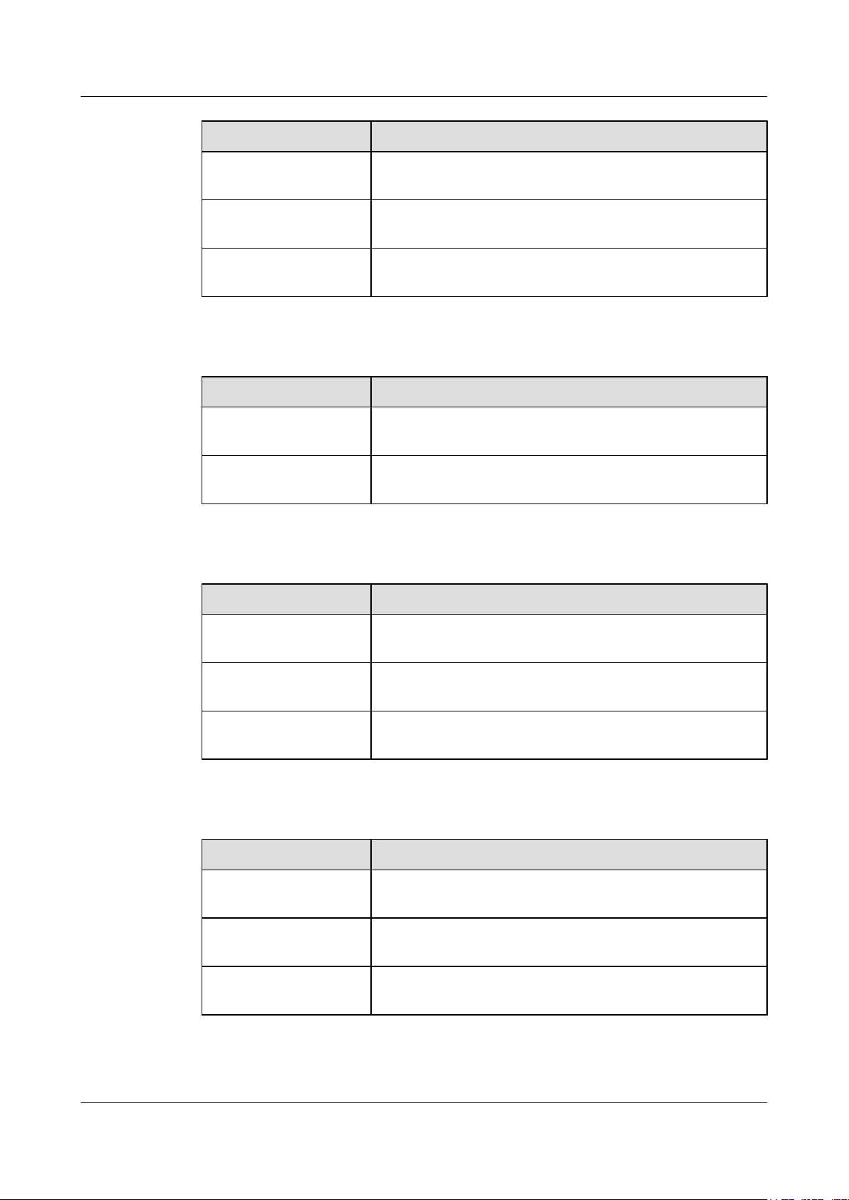
Figure 2-1, Figure 2-2 and Figure 2-3 show the appearance of the HG8240/HG8245/
HG8247.
2-2 Huawei Proprietary and Confidential
Copyright © Huawei Technologies Co., Ltd.
Issue 02 (2011-01-26)
Page 25
EchoLife HG8240/HG8245/HG8247 GPON Terminal
Service Manual 2 System Overview
Figure 2-1 Appearance of the HG8240
Figure 2-2 Appearance of the HG8245
Issue 02 (2011-01-26) Huawei Proprietary and Confidential
Copyright © Huawei Technologies Co., Ltd.
2-3
Page 26
2 System Overview
EchoLife HG8240/HG8245/HG8247 GPON Terminal
Service Manual
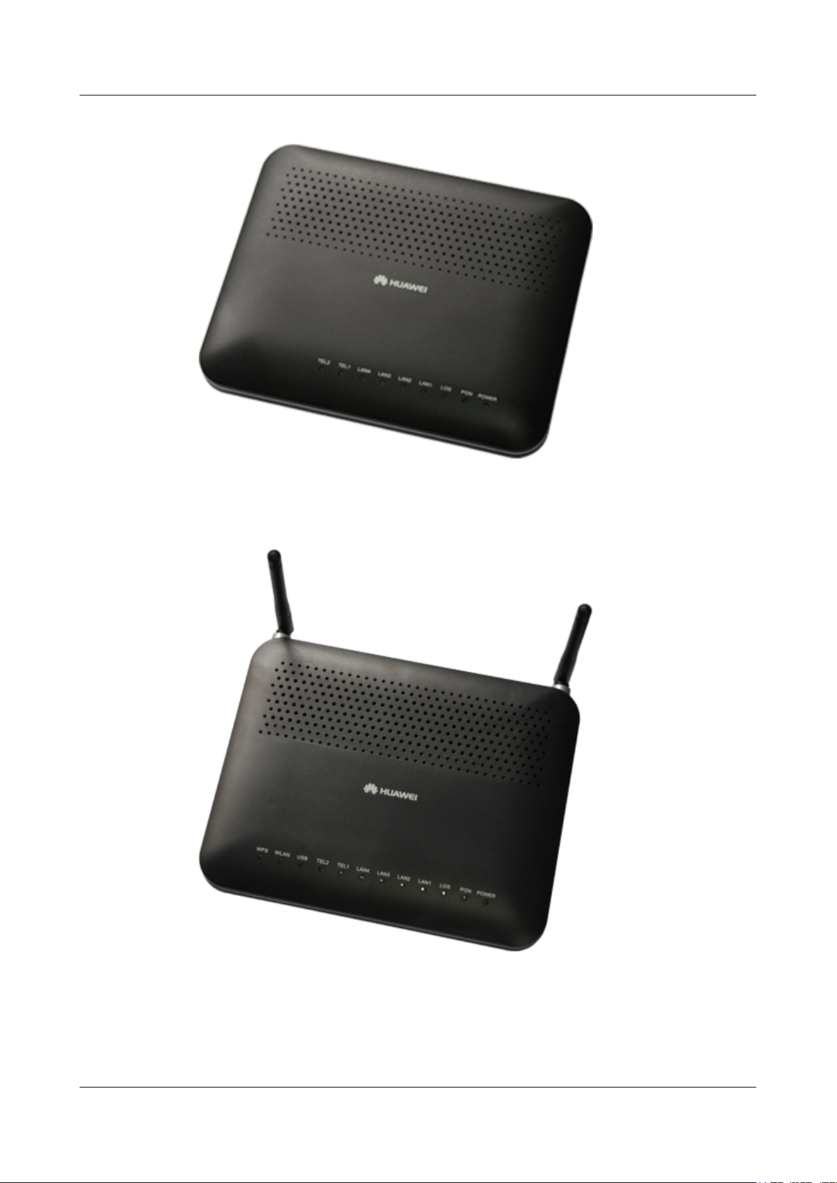
Figure 2-3 Appearance of the HG8247
2.1.2 Ports
This topic provides the appearance of the ports on the HG8240/HG8245/HG8247 and describes
the functions of the ports.
Ports on the HG8240
Figure 2-4 and Figure 2-5 show the ports on the rear panel and side panel of the HG8240
respectively.
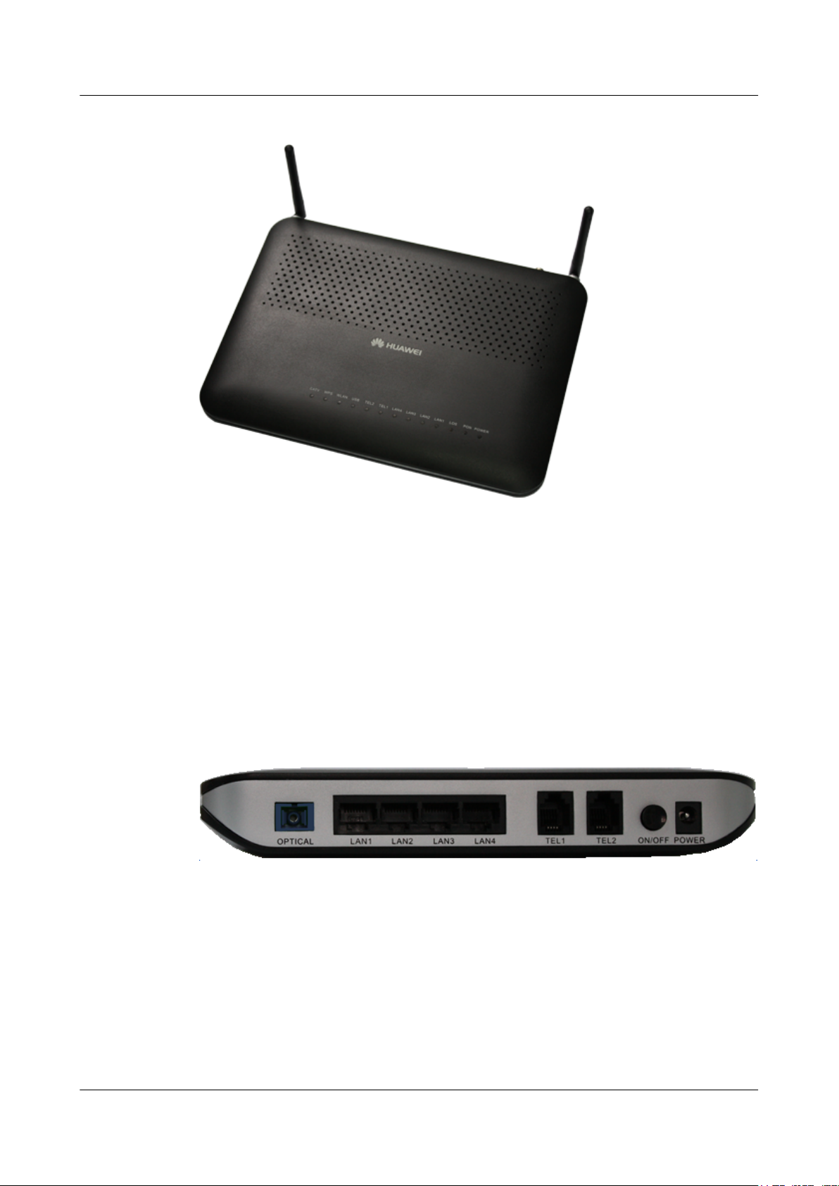
Figure 2-4 Ports on the rear panel of the HG8240
2-4 Huawei Proprietary and Confidential
Copyright © Huawei Technologies Co., Ltd.
Issue 02 (2011-01-26)
Page 27
EchoLife HG8240/HG8245/HG8247 GPON Terminal
Service Manual 2 System Overview
Table 2-1 Descriptions of the ports on the rear panel of the HG8240
Port and Button Function
Indicates the optical port. The optical port is equipped with a
rubber plug and is connected to an optical fiber for upstream
OPTICAL
transmission.
The type of the optical connector connected to the OPTICAL
port is SC/APC.
LAN1-LAN4
TEL1-TEL2
ON/OFF
POWER
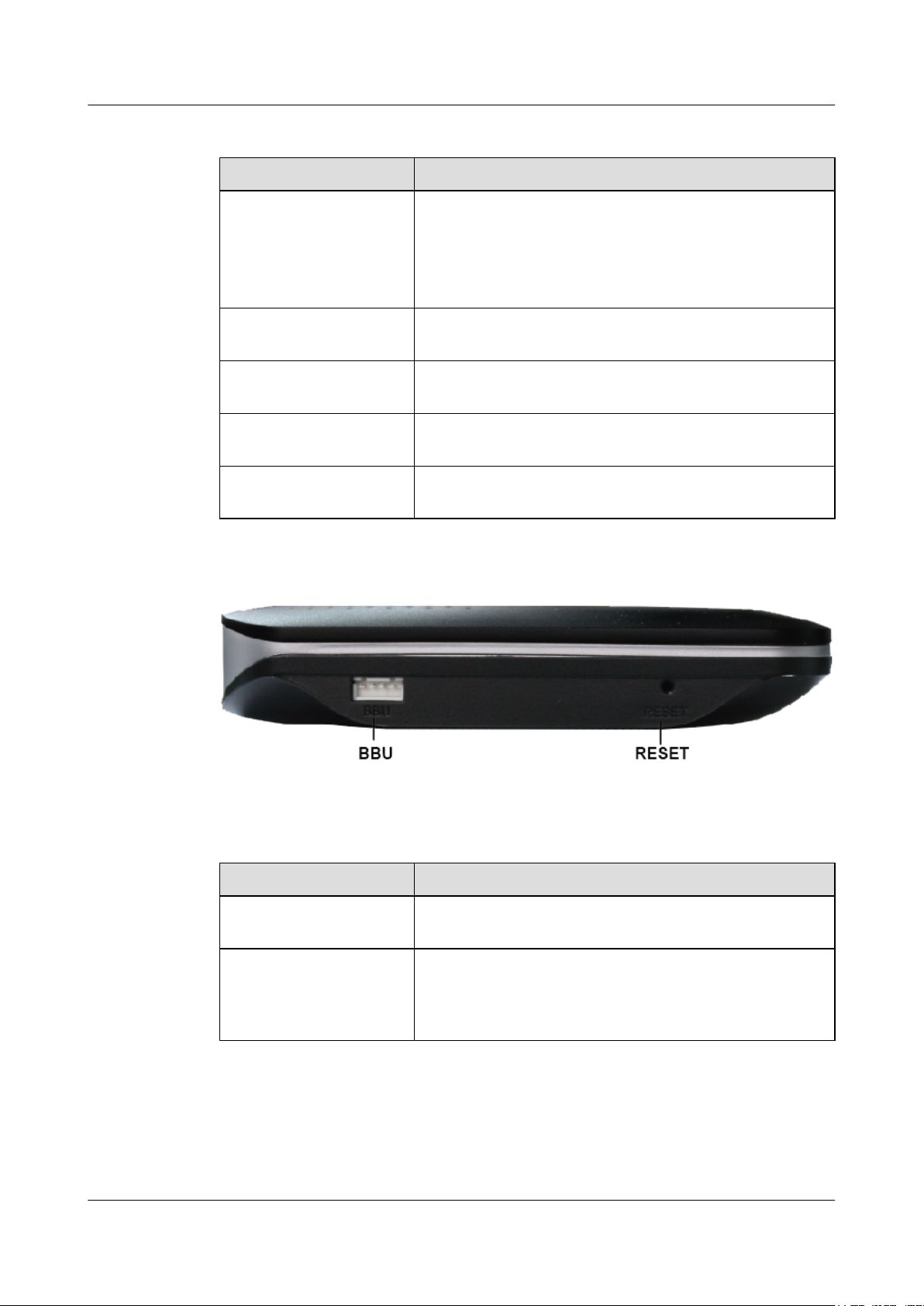
Figure 2-5 Ports on the side panel of the HG8240
Indicate auto-sensing 10/100/1000M Base-T Ethernet ports
(RJ-45), used for connecting to PCs or IP set-top boxes (STBs).
Indicate VoIP telephone ports (RJ-11), used for connecting to
the ports on telephone sets.
Indicates the power-on/power-off button, used for powering on
or powering off the device.
Indicates the power port, used for connecting to the power
adapter or backup battery.
Table 2-2 Descriptions of the ports on the side panel of the HG8240
Port and Button
BBU
RESET
Function
Indicates the external backup battery monitoring port, used for
connecting to the backup battery for monitoring the battery.
Indicates the reset button. Press the button for a short time to
reset the device; press the button for a long time (longer than
10s) to restore the device to the default settings and reset the
device.
Ports on the HG8245
Figure 2-6 and Figure 2-7 show the ports on the rear panel and side panel of the HG8245
respectively.
Issue 02 (2011-01-26) Huawei Proprietary and Confidential
Copyright © Huawei Technologies Co., Ltd.
2-5
Page 28
2 System Overview
EchoLife HG8240/HG8245/HG8247 GPON Terminal
Service Manual
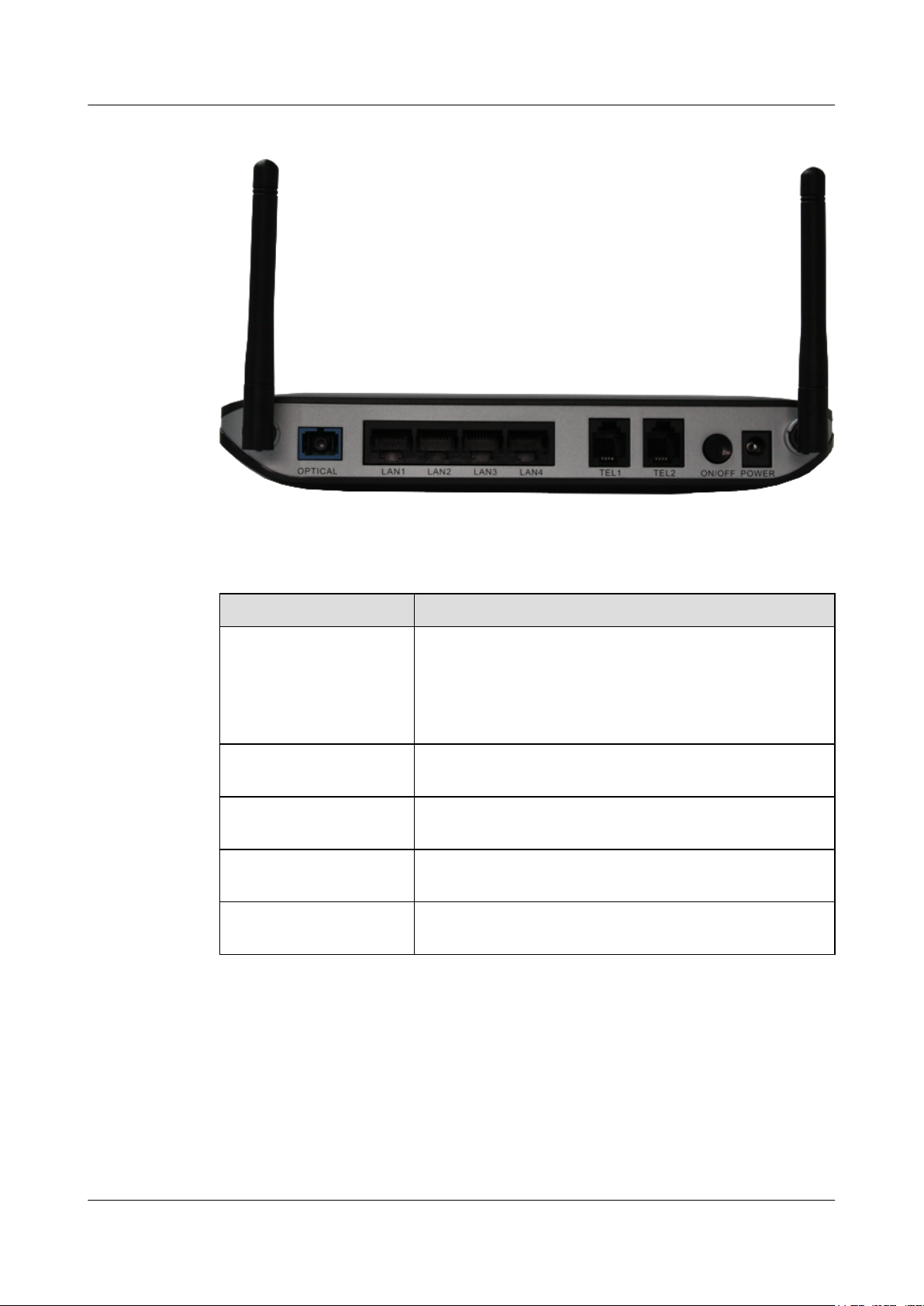
Figure 2-6 Ports on the rear panel of the HG8245
Table 2-3 Descriptions of the ports on the rear panel of the HG8245
Port and Button
Function
Indicates the optical port. The optical port is equipped with a
rubber plug and is connected to an optical fiber for upstream
OPTICAL
transmission.
The type of the optical connector connected to the OPTICAL
port is SC/APC.
LAN1-LAN4
TEL1-TEL2
ON/OFF
POWER
Indicate auto-sensing 10/100/1000M Base-T Ethernet ports
(RJ-45), used for connecting to PCs or IP STBs.
Indicate VoIP telephone ports (RJ-11), used for connecting to
the ports on telephone sets.
Indicates the power-on/power-off button, used for powering on
or powering off the device.
Indicates the power port, used for connecting to the power
adapter or backup battery.
2-6 Huawei Proprietary and Confidential
Copyright © Huawei Technologies Co., Ltd.
Issue 02 (2011-01-26)
Page 29

EchoLife HG8240/HG8245/HG8247 GPON Terminal
Service Manual 2 System Overview
Figure 2-7 Ports on the side panel of the HG8245
Table 2-4 Descriptions of the ports on the side panel of the HG8245
Port and Button
BBU
USB
WLAN
WPS Indicates the WLAN data encryption switch.
RESET
Ports on the HG8247
Function
Indicates the external backup battery monitoring port, used for
connecting to the backup battery for monitoring the battery.
Indicates the USB host port, used for connecting to a USB
storage device.
Indicates the WLAN button, used for enabling or disabling the
WLAN function.
Indicates the reset button. Press the button for a short time to
reset the device; press the button for a long time (longer than
10s) to restore the device to the default settings and reset the
device.
Figure 2-8 and Figure 2-9 show the ports on the rear panel and side panel of the HG8247
respectively.
Issue 02 (2011-01-26) Huawei Proprietary and Confidential
Copyright © Huawei Technologies Co., Ltd.
2-7
Page 30
2 System Overview
EchoLife HG8240/HG8245/HG8247 GPON Terminal
Service Manual
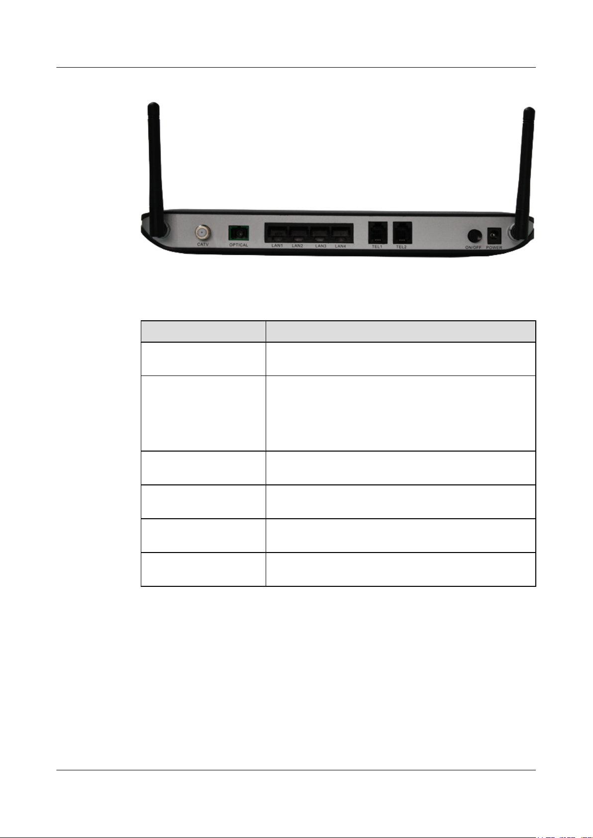
Figure 2-8 Ports on the rear panel of the HG8247
Table 2-5 Descriptions of the ports on the rear panel of the HG8247
Port and Button Function
CATV
OPTICAL
LAN1-LAN4
TEL1-TEL2
ON/OFF
POWER
Indicates the radio frequency (RF) port, used for connecting to
a TV set.
Indicates the optical port. The optical port is equipped with a
rubber plug and is connected to an optical fiber for upstream
transmission.
The type of the optical connector connected to the OPTICAL
port is SC/APC.
Indicate auto-sensing 10/100/1000M Base-T Ethernet ports
(RJ-45), used for connecting to PCs or IP STBs.
Indicate VoIP telephone ports (RJ-11), used for connecting to
the ports on telephone sets.
Indicates the power-on/power-off button, used for powering on
or powering off the device.
Indicates the power port, used for connecting to the power
adapter or backup battery.
2-8 Huawei Proprietary and Confidential
Copyright © Huawei Technologies Co., Ltd.
Issue 02 (2011-01-26)
Page 31

EchoLife HG8240/HG8245/HG8247 GPON Terminal
Service Manual 2 System Overview
Figure 2-9 Ports on the side panel of the HG8247
Table 2-6 Descriptions of the ports on the side panel of the HG8247
Port and Button
BBU
USB
WLAN
WPS Indicates the WLAN data encryption switch.
RESET
Function
Indicates the external backup battery monitoring port, used for
connecting to the backup battery for monitoring the battery.
Indicate the USB host port, used for connecting to a USB
storage device.
Indicates the WLAN button, used for enabling or disabling the
WLAN function.
Indicates the reset button. Press the button for a short time to
reset the device; press the button for a long time (longer than
10s) to restore the device to the default settings and reset the
device.
2.1.3 LEDs
This topic provides the appearance of the LEDs on the HG8240/HG8245/HG8247 and describes
the indications of these LEDs.
Figure 2-10, Figure 2-11 and Figure 2-12 show the LEDs on the HG8240, HG8245 and
HG8247 respectively.
Issue 02 (2011-01-26) Huawei Proprietary and Confidential
Copyright © Huawei Technologies Co., Ltd.
2-9
Page 32

2 System Overview
EchoLife HG8240/HG8245/HG8247 GPON Terminal
Service Manual
Figure 2-10 LEDs on the HG8240
2-10 Huawei Proprietary and Confidential
Copyright © Huawei Technologies Co., Ltd.
Issue 02 (2011-01-26)
Page 33

EchoLife HG8240/HG8245/HG8247 GPON Terminal
Service Manual 2 System Overview
Figure 2-11 LEDs on the HG8245
Figure 2-12 LEDs on the HG8247
Issue 02 (2011-01-26) Huawei Proprietary and Confidential
Copyright © Huawei Technologies Co., Ltd.
2-11
Page 34

2 System Overview
EchoLife HG8240/HG8245/HG8247 GPON Terminal
Service Manual
Table 2-7 Indications of the LEDs on the HG8240/HG8245/HG8247
Silk Screen Name Status Indication
Green: always on The device is powered on.
POWER
PON
LOS
LAN1-LAN4
TEL1-TEL2
Power supply
LED
Authentication
LED
Connection
LED
Ethernet port
LED
Voice telephone
port LED
Orange: always
on
The device is powered by the
backup battery.
Off The power supply is cut off.
See Table 2-8.
See Table 2-8.
Always on
Blinks
Off
Always on
Blinks quickly
(twice per
second)
Blinks slowly
(once two
seconds)
The Ethernet connection is in the
normal state.
Data is being transmitted on the
Ethernet port.
The Ethernet connection is not set
up.
The connection to the voice server
is set up.
The connection to the voice server
is set up and the telephone is in the
off-hook or ringing state.
The ONT is registering with the
voice server.
Off
Always on
USB USB port LED
Blinks quickly
(twice per
second)
Off
Always on The WLAN function is enabled.
WLAN
2-12 Huawei Proprietary and Confidential
WLAN port
LED
Copyright © Huawei Technologies Co., Ltd.
Blinks
The connection to the voice server
is not set up.
The USB port is connected and is
working in the host mode, but no
data is being transmitted.
Data is being transmitted on the
USB port.
The system is not powered on or the
USB port is not connected.
Data is being transmitted on the
WLAN port.
Issue 02 (2011-01-26)
Page 35

EchoLife HG8240/HG8245/HG8247 GPON Terminal
Service Manual 2 System Overview
Silk Screen Name Status Indication
Off The WLAN function is disabled.
Always on The WPS function is enabled.
WPS WPS port LED
CATV CATV port LED
Table 2-8 Indications of PON and LOS LEDs
LED Status
No.
PON LOS
1 Off Off The ONT is disabled by the OLT.
2 Blinks quickly
(twice per
second)
3 Always on Off
Blinks
Off The WPS function is disabled.
Always on
Off
Off The ONT is attempting to set up a
A Wi-Fi terminal is accessing the
system.
The CATV function is enabled and
CATV signals are received.
The CATV function is disabled or
CATV signals are not received.
Indication
connection to the OLT.
The connection between the ONT
and the OLT is set up.
4 Off Blinks slowly
(once two
seconds)
Blinks quickly
5
(twice per
second)
Blinks quickly
(twice per
second)
2.2 Typical Network Applications
This topic describes the typical network applications of the HG8240/HG8245/HG8247.
As a network terminal, the HG8240/HG8245/HG8247 is deployed at the GPON access layer
and connects home users and SOHO users to the Internet through optical upstream ports. On the
local area network (LAN) side, the HG8240/HG8245/HG8247 provides abundant hardware
ports to meet various network requirements of home users and SOHO users.
Network Topology of the HG8240
Figure 2-13 shows the position of the HG8240 in a network.
The Rx optical power of the ONT is
lower than the optical receiver
sensitivity.
The OLT detects that the ONT is a
rogue ONT.
Issue 02 (2011-01-26) Huawei Proprietary and Confidential
Copyright © Huawei Technologies Co., Ltd.
2-13
Page 36

2 System Overview
EchoLife HG8240/HG8245/HG8247 GPON Terminal
Service Manual
Figure 2-13 Network topology of the HG8240
l In the upstream direction, the HG8240 is connected to the optical splitter and the network-
side OLT through the passive optical network (PON) port, namely the OPTICAL port, to
provide integrated access services.
l In the downstream direction, the HG8240 is connected to various terminals through the
following LAN-side ports to implement the triple play service:
– Four 10/100/1000M Base-T Ethernet ports, which can be connected to terminals such
as PCs, STBs, and video phoned to provide the high-speed data and video services.
– Two TEL ports, which can be connected to telephone sets or fax machines to provide
superior and cost-effective voice over IP (VoIP), fax over IP (FoIP), and modem over
IP (MoIP) services.
Network Topology of the HG8245
Figure 2-14 shows the position of the HG8245 in a network.
Figure 2-14 Network topology of the HG8245
2-14 Huawei Proprietary and Confidential
Copyright © Huawei Technologies Co., Ltd.
Issue 02 (2011-01-26)
Page 37

EchoLife HG8240/HG8245/HG8247 GPON Terminal
Service Manual 2 System Overview
l In the upstream direction, the HG8245 is connected to the optical splitter and the network-
side OLT through the PON port, namely the OPTICAL port, to provide integrated access
services.
l In the downstream direction, the HG8245 is connected to various terminals through the
following LAN-side ports to implement the triple play service:
– Four 10/100/1000M Base-T Ethernet ports, which can be connected to terminals such
as PCs, STBs, and video phones to provide the high-speed data and video services.
– Two TEL ports, which can be connected to telephone sets or fax machines to provide
superior and cost-effective VoIP, FoIP, and MoIP services.
– Two Wi-Fi antennas, which can connect to Wi-Fi terminals wirelessly to provide a
secure and reliable high-speed wireless network.
– One USB port, which can be connected to a USB storage device to provide convenient
storage and file sharing services within a home network.
Network Topology of the HG8247
Figure 2-15 shows the position of the HG8247 in a network.
Figure 2-15 Network topology of the HG8247
l In the upstream direction, the HG8247 is connected to the optical splitter and the network-
side OLT through the PON port, namely the OPTICAL port, to provide integrated access
services.
l In the downstream direction, the HG8247 is connected to various terminals through the
following LAN-side ports to implement the triple play service:
– One CATV port, which can be connected to a TV set to provide high-quality CATV
service transmission.
– Four 10/100/1000M Base-T Ethernet ports, which can be connected to terminals such
as PCs, STBs, and video phones to provide the high-speed data and video services.
– Two TEL ports, which can be connected to telephone sets or fax machines to provide
superior and cost-effective VoIP, FoIP, and MoIP services.
Issue 02 (2011-01-26) Huawei Proprietary and Confidential
Copyright © Huawei Technologies Co., Ltd.
2-15
Page 38

2 System Overview
EchoLife HG8240/HG8245/HG8247 GPON Terminal
Service Manual
– Two Wi-Fi antennas, which can connect to Wi-Fi terminals wirelessly to provide a
secure and reliable high-speed wireless network.
– One USB port, which can be connected to a USB storage device to provide convenient
storage and file sharing services within a home network.
2-16 Huawei Proprietary and Confidential
Copyright © Huawei Technologies Co., Ltd.
Issue 02 (2011-01-26)
Page 39

EchoLife HG8240/HG8245/HG8247 GPON Terminal
Service Manual 3 Configuration Guide
3 Configuration Guide
About This Chapter
This topic describes how to configure the services of the HG8240/HG8245/HG8247 through
the Web page.
3.1 OMCI Protocol
This topic describes the principles of the OMCI protocol and how to set up an OMCI channel.
3.2 Logging In Through the Web Page
This topic describes the data plan for and procedure of logging in through the Web Page.
3.3 Overview of the Web Page
This topic describes the Web page of the HG8240/HG8245/HG8247.
Issue 02 (2011-01-26) Huawei Proprietary and Confidential
Copyright © Huawei Technologies Co., Ltd.
3-1
Page 40

3 Configuration Guide
3.1 OMCI Protocol
This topic describes the principles of the OMCI protocol and how to set up an OMCI channel.
3.1.1 Principles of the OMCI Protocol
This topic describes the principles of the OMCI protocol.
3.1.2 Setting Up an OMCI Channel
This topic describes how to set up an OMCI channel.
3.1.1 Principles of the OMCI Protocol
This topic describes the principles of the OMCI protocol.
The optical network termination management and control interface (OMCI) protocol is defined
in ITU-T Recommendation G.984.4. OMCI defines the format and the mechanism of the
messages exchanged between the OLT and the ONT. OMCI also analyzes the service model of
the ONT at a finer grain and defines a series of management entities used for service description.
OMCI specifies the format of the messages exchanged between the OLT and the ONT and the
mechanisms of confirmation and retransmission. In this way, OMCI provides a logical channel
for communication. Enabled with OMCI, the OLT supports the management and configuration
of various types of ONTs, the offline configuration of ONTs, and the configuration recovery of
online ONTs. Based on this mechanism, the ONT need not save the configuration information
locally. This helps to provision services and maintain the terminal.
EchoLife HG8240/HG8245/HG8247 GPON Terminal
Service Manual
3.1.2 Setting Up an OMCI Channel
This topic describes how to set up an OMCI channel.
Context
The process of setting up an OMCI channel between the OLT and the ONT is performed
automatically and requires no manual operation.
Procedure
Step 1 After being powered on, the ONT interacts with the OLT through Physical Layer OAM
(PLOAM) messages to complete the registration.
Step 2 From the PLOAM messages, the OLT learns whether the ONT supports the OMCI protocol. If
the ONT supports the OMCI protocol, an OMCI channel is set up between the OLT and the
ONT.
Step 3 After the OMCI channel is set up, the OLT issues the configuration and management information
about the ONT to the ONT through the OMCI channel, and the ONT uploads its status and alarm
information to the OLT through the OMCI channel.
NOTE
l The PLOAM protocol is defined in ITU-T Recommendation G.984.3 and is used for the operation,
maintenance, and management at the physical layer.
l OMCI is a master-slave management protocol. The OLT functions as the master device and the ONT
as the slave device. The OLT controls multiple ONTs through the OMCI channel.
----End
3-2 Huawei Proprietary and Confidential
Copyright © Huawei Technologies Co., Ltd.
Issue 02 (2011-01-26)
Page 41

EchoLife HG8240/HG8245/HG8247 GPON Terminal
Service Manual 3 Configuration Guide
3.2 Logging In Through the Web Page
This topic describes the data plan for and procedure of logging in through the Web Page.
3.2.1 Data Plan
This topic describes the data plan for logging in through the Web Page.
3.2.2 Procedure
This topic describes how to log in through the Web Page.
3.2.1 Data Plan
This topic describes the data plan for logging in through the Web Page.
Before setting up the configuration environment, set parameters as listed in Table 3-1.
Table 3-1 Parameters required for setting up the configuration environment
Parameter Description
User name and password Default settings:
l Administrator:
– User name: telecomadmin
– Password: admintelecom
l Common user:
– User name: root
– Password: admin
LAN IP address and subnet mask
IP address and subnet mask of the PC Set the IP address of the PC to be in the same
Default settings:
l IP address: 192.168.100.1
l Subnet mask: 255.255.255.0
subnet as the LAN IP address of the HG8240/
HG8245/HG8247.
For example:
l IP address: 192.168.100.100
l Subnet mask: 255.255.255.0
The differences between the configuration rights of an administrator and a common user are as
follows:
l An administrator has the right to configure all the parameters on the Web Page.
l The parameters of certain nodes are unavailable to a common user. Such parameters are:
– LAN > LAN Port Work Mode
– Voice
Issue 02 (2011-01-26) Huawei Proprietary and Confidential
Copyright © Huawei Technologies Co., Ltd.
3-3
Page 42

3 Configuration Guide
l A common user has no right to configure the parameters of certain nodes, such as WAN >
3.2.2 Procedure
This topic describes how to log in through the Web Page.
Procedure
Step 1 Use a network cable to connect a LAN port of the HG8240/HG8245/HG8247 to a PC.
Step 2 Ensure that the Internet Explorer of the PC does not use the proxy server. The following considers
Internet Explorer 6.0 as an example to describe how to check whether the Internet Explorer uses
the proxy server.
EchoLife HG8240/HG8245/HG8247 GPON Terminal
Service Manual
– Network Application > Portal Configuration and Network Application > Terminal
Limit Configuration
– System Tools > Time Setting, System Tools > TR-069, and System Tools > ONT
Mode
– Download Configuration File and Upload Configuration File on the System Tools
> Configuration File page
WAN Configuration.
1. Start the Internet Explorer, and choose Tools > Internet Options from the main menu of
the Internet Explorer window. Then, the Internet Options window is displayed.
2. Click Connections to display the Connections tab page, and then click LAN settings.
3. In the Local Area Network (LAN) Settings window, deselect Use a proxy server for
your LAN (These settings will not apply to dial-up or VPN connections). under Proxy
server. If this option is selected, deselect it to cancel the settings, and then click OK.
Step 3 Log in through the Web Page.
1. Input http://192.168.100.1 in the address bar of the Internet Explorer (192.168.100.1 is the
default IP address of the HG8240/HG8245/HG8247), and then press Enter to display the
login window.
2. In the login window, input the user name and password. (For default settings of the user
name and password, see 3.2.1 Data Plan.) After the password authentication is successful,
the Web Page is displayed.
----End
3.3 Overview of the Web Page
This topic describes the Web page of the HG8240/HG8245/HG8247.
The Web page of the HG8240/HG8245/HG8247 consists of the following parts:
l Navigation tree on the left: Click a link and then perform the configuration on the displayed
page.
l Configuration management pane on the right: The contents displayed on the right depend
on the function selected in the navigation tree on the left. For details, see the corresponding
configuration page.
3-4 Huawei Proprietary and Confidential
Copyright © Huawei Technologies Co., Ltd.
Issue 02 (2011-01-26)
Page 43

EchoLife HG8240/HG8245/HG8247 GPON Terminal
Service Manual 3 Configuration Guide
NOTE
l The Web page may vary with the software version. The Web page for an administrator and that for a
common user are different. This section considers the Web page for an administrator as an example.
l The HG8240/HG8245/HG8247 has similar Web pages. This section considers the HG8247 as an
example to describe its Web page. The HG8240 does not provide the Wi-Fi function and therefore its
Web page does not have a Wi-Fi node.
3.3.1 Status
This topic describes how to query the information about the WAN interface, VoIP interface, and
Wi-Fi port through the Web page.
3.3.2 WAN
This topic describes how to configure the WAN interface through the Web page.
3.3.3 LAN
This topic describes how to set the working mode of the LAN port, the LAN host, and the DHCP
server through the Web page.
3.3.4 WLAN
This topic describes how to perform basic and advanced configurations of the WLAN through
the Web page.
3.3.1 Status
3.3.5 Security
This topic describes how to configure the IP address filter, MAC address filter, DoS, and ONT
access control through the Web page.
3.3.6 Route
This topic describes how to configure the default route and static route through the Web page.
3.3.7 Forward Rules
This topic describes how to configure the DMZ, port mapping, and port trigger through the Web
page.
3.3.8 Network Applications
This topic describes how to configure the USB, ALG, UPnP, and ARP through the Web page.
3.3.9 Voice
This topic describes how to configure the voice service through the Web page.
3.3.10 System Tools
This topic describes how to use the system tools on the Web page, including using the tools to
restart the device, restore the default configuration, and conduct the test.
This topic describes how to query the information about the WAN interface, VoIP interface, and
Wi-Fi port through the Web page.
WAN Information
Click the Status tab and then choose WAN Information from the navigation tree. In the pane
on the right, you can view the status of the WAN interface, mode of obtaining an IP address, IP
address, and subnet mask, as shown in Figure 3-1.
Issue 02 (2011-01-26) Huawei Proprietary and Confidential
Copyright © Huawei Technologies Co., Ltd.
3-5
Page 44

3 Configuration Guide
Figure 3-1 WAN Information
VoIP Information
Click the Status tab and then choose VoIP Information from the navigation tree. Then, in the
pane on the right, you can query the information such as user status and call status. The SIP
configuration page is slightly different from the H.248 configuration page, as shown in Figure
3-2 and Figure 3-3.
EchoLife HG8240/HG8245/HG8247 GPON Terminal
Service Manual
Figure 3-2 VoIP Information - SIP
Figure 3-3 VoIP Information - H.248
3-6 Huawei Proprietary and Confidential
Copyright © Huawei Technologies Co., Ltd.
Issue 02 (2011-01-26)
Page 45

EchoLife HG8240/HG8245/HG8247 GPON Terminal
Service Manual 3 Configuration Guide
If the VoIP service needs to be restarted, click Reset VoIP in the pane on the right.
WLAN Information
Click the Status tab and then choose WLAN Information from the navigation tree. Then, in
the pane on the right, you can query the information such as WLAN status, WLAN packet
statistics, and SSID, as shown in Figure 3-4.
Figure 3-4 WLAN Information
l In the pane on the right, click Enable or Disable to enable or disable the Wi-Fi function.
l Click the link in blue to go to the corresponding configuration page.
Eth Port Information
Click the Status tab and then choose Eth Port Information from the navigation tree. In the
pane on the right, you can view the duplex mode, speed, and status of the ETH port, as shown
in Figure 3-5.
Figure 3-5 Eth Port Information
Issue 02 (2011-01-26) Huawei Proprietary and Confidential
Copyright © Huawei Technologies Co., Ltd.
3-7
Page 46

3 Configuration Guide
DHCP Information
Click the Status tab and then choose DHCP Information from the navigation tree. In the pane
on the right, you can view the basic information about the DHCP server, including the IP address
assigned to the connected PC through DHCP, MAC address, and remaining lease time, as shown
in Figure 3-6.
Figure 3-6 DHCP Information
EchoLife HG8240/HG8245/HG8247 GPON Terminal
Service Manual
Optical Information
Click the Status tab and then choose Optical Information from the navigation tree. In the pane
on the right, you can view the optical status, transmit optical power, receive optical power of
the optical module, as shown in Figure 3-7.
Figure 3-7 Optical Information
Battery Information
Click the Status tab and then choose Battery Information from the navigation tree. In the pane
on the right, you can view the connection status and available capacity of the external standby
battery, as shown in Figure 3-8.
3-8 Huawei Proprietary and Confidential
Copyright © Huawei Technologies Co., Ltd.
Issue 02 (2011-01-26)
Page 47

EchoLife HG8240/HG8245/HG8247 GPON Terminal
Service Manual 3 Configuration Guide
Figure 3-8 Battery Information
Device Information
Click the Status tab and then choose Device Information from the navigation tree. In the pane
on the right, you can view the product name, hardware version, and software version, as shown
in Figure 3-9.
Figure 3-9 Device Information
Remote Management
Click the Status tab and then choose Remote Manage from the navigation tree. In the right
pane, view the remote management status and service application status, as shown in Figure
3-10.
Issue 02 (2011-01-26) Huawei Proprietary and Confidential
Copyright © Huawei Technologies Co., Ltd.
3-9
Page 48

3 Configuration Guide
Figure 3-10 Remote management
3.3.2 WAN
This topic describes how to configure the WAN interface through the Web page.
WAN Configuration
EchoLife HG8240/HG8245/HG8247 GPON Terminal
Service Manual
l WAN Configuration - route
1. Click the WAN tab and then choose WAN Configuration from the navigation tree.
In the pane on the right, click New. In the dialog box that is displayed, set Mode to
Route, as shown in Figure 3-11.
Figure 3-11 WAN Configuration - Route
2. Click Apply.
Table 3-2 describes the parameters related to the WAN in route mode.
3-10 Huawei Proprietary and Confidential
Copyright © Huawei Technologies Co., Ltd.
Issue 02 (2011-01-26)
Page 49

EchoLife HG8240/HG8245/HG8247 GPON Terminal
Service Manual 3 Configuration Guide
Table 3-2 Parameters related to the WAN in route mode
Parameter Description
Enable Indicates whether to enable the WAN
connection.
Service List Indicates the service type of the WAN
interface. It can be set to TR069,
INTERNET, TR069_INTERNET, VOIP,
TR069_VOIP, VOIP_INTERNET,
TR069_VOIP_INTERNET, IPTV or
OTHER.
VLAN ID Indicates the VLAN ID. It ranges from 1 to
4094.
The VLAN ID must be the same as the
CVLAN ID on the OLT.
802.1p Indicates the 802.1p value. It ranges from
0 to 7.
IP Acquisition Mode Indicates the mode of obtaining an IP
address on the ONT. It can be set to DHCP,
static, or PPPoE.
l In DHCP mode, the IP address is
dynamically obtained.
l In static mode, the IP address is set
statically. You need to enter the IP
address, subnet mask, IP addresses of
the active and standby DNS servers,
and default gateway.
l In PPPoE mode, you need to enter the
user name and password.
NAT
Indicates whether to enable the NAT
function.
Vendor ID Set the option 60 field on the DHCP client.
The IP address can be obtained from the
DHCP server only when the option 60 field
is the same as the setting on the upper-layer
DHCP server. When IP Acquisition
Mode is set to DHCP, this parameter is
configurable.
Binding options
Used to bind the WAN interface to the
LAN port or to the wireless SSID.
NOTE
Issue 02 (2011-01-26) Huawei Proprietary and Confidential
Copyright © Huawei Technologies Co., Ltd.
Before setting the binding options, set the work
mode of the LAN port or the wireless SSID. The
binding options can be set only after the work
mode or wireless SSID is successfully set. For
details, see LAN Port Work Mode and
WLAN Configuration.
3-11
Page 50

3 Configuration Guide
EchoLife HG8240/HG8245/HG8247 GPON Terminal
Service Manual
l WAN Configuration - bridge
1. Click the WAN tab and then choose WAN Configuration from the navigation tree.
In the pane on the right, click New. In the dialog box that is displayed, set Mode to
Bridge, as shown in Figure 3-12.
Figure 3-12 WAN Configuration - Bridge
2. Click Apply.
Table 3-3 describes the parameters related to the WAN in bridge mode.
Table 3-3 Parameters related to the WAN in bridge mode
Parameter
Description
Enable Indicates whether to enable the WAN
connection.
Service List Indicates the service type of the WAN
interface. It can be set to TR069, IPTV or
OTHER.
VLAN ID Indicates the VLAN ID. It ranges from 1 to
4094.
The VLAN ID must be the same as the
CVLAN ID on the OLT.
MultiCast VLAN ID The multicast VLAN ID ranges from 1 to
4094.
The multicast VLAN ID must be the same
as the multicast VLAN ID on the OLT.
3-12 Huawei Proprietary and Confidential
Copyright © Huawei Technologies Co., Ltd.
Issue 02 (2011-01-26)
Page 51

EchoLife HG8240/HG8245/HG8247 GPON Terminal
Service Manual 3 Configuration Guide
Parameter Description
Bridge Type It can be set to IP or PPPoE.
Binding options Used to bind the WAN interface to the
LAN port or to the wireless SSID.
NOTE
Before setting the binding options, set the work
mode of the LAN port or the wireless SSID. The
binding options can be set only after the work
mode or wireless SSID is successfully set. For
details, see LAN Port Work Mode and
WLAN Configuration.
NOTE
l WAN in route mode: The ONT functions as a gateway. The IP address of the ONT can be obtained
through DHCP, Static, or PPPoE. The IP address of the PC connected to the ONT can be obtained from
the DHCP address pool of the ONT or can be set manually.
l WAN in bridge mode: The ONT functions as a relay and does not process data. The ONT does not
obtain the IP address allocated by the upper-layer device and it does not allow manual configuration
of a static IP address. The IP address of the device connected to the ONT can be obtained through
DHCP, PPPoE, or static.
l In the case of the DHCP mode, you need to set the DHCP relay. After configuration is complete,
the user-side IP address is obtained from the upper-layer device. For the detailed procedure, see
DHCP Server Configuration.
l In the case of the PPPoE mode, the user-side IP address is obtained through PPPoE authentication
of the upper-layer device.
3.3.3 LAN
This topic describes how to set the working mode of the LAN port, the LAN host, and the DHCP
server through the Web page.
LAN Port Work Mode
1. Click the LAN tab and then choose LAN Port Work Mode from the navigation tree. In
the pane on the right, determine whether the LAN port works in layer 3 mode, as shown in
Figure 3-13.
Figure 3-13 LAN Port Work Mode
Issue 02 (2011-01-26) Huawei Proprietary and Confidential
Copyright © Huawei Technologies Co., Ltd.
3-13
Page 52

3 Configuration Guide
NOTE
If the check box corresponding to the LAN port is selected, it indicates that the LAN port works in
layer 3 mode, that is, the gateway mode; if the check box corresponding to the LAN port is deselected,
it indicates that the LAN port works in layer 2 mode, that is, the bridge mode.
By default, the check boxes corresponding to all LAN ports are deselected, that is, all LAN ports
work in layer 2 mode.
2. Click Apply.
LAN Host Configuration
1. Click the LAN tab and then choose LAN Host Configuration from the navigation tree. In
the pane on the right, set the management IP address and subnet mask of the LAN host, as
shown in Figure 3-14.
Figure 3-14 LAN Host Configuration
EchoLife HG8240/HG8245/HG8247 GPON Terminal
Service Manual
NOTE
The IP address of the device connected to the LAN port must be in the same subnet as the management
IP address. In this way, you can access an ONT through the Web page and perform query and
management. You can manually set the IP address of the device connected to the LAN port to be on
the same network segment as the management IP address, or start the DHCP server to set the IP
address in the DHCP address pool to be on the same network segment as the management IP address.
For details, see DHCP Server Configuration.
2. Click Apply.
DHCP Server Configuration
1. Click the LAN tab and then choose DHCP Server Configuration from the navigation tree.
In the pane on the right, you can configure the LAN side DHCP address pool for the ONT
that functions as a gateway. After the configuration, the PC connected to the LAN port can
automatically obtain an IP address from the address pool, as shown in Figure 3-15.
3-14 Huawei Proprietary and Confidential
Copyright © Huawei Technologies Co., Ltd.
Issue 02 (2011-01-26)
Page 53

EchoLife HG8240/HG8245/HG8247 GPON Terminal
Service Manual 3 Configuration Guide
Figure 3-15 DHCP Server Configuration
2. Click Apply.
Table 3-4 describes the parameters related to the DHCP server.
Table 3-4 Parameters related to the DHCP server
Parameter
Description
Enable primary DHCP server Indicates whether to enable the primary
DHCP server. If the check box is selected,
you can set the primary DHCP server.
Issue 02 (2011-01-26) Huawei Proprietary and Confidential
Copyright © Huawei Technologies Co., Ltd.
3-15
Page 54

3 Configuration Guide
EchoLife HG8240/HG8245/HG8247 GPON Terminal
Service Manual
Parameter Description
Enable DHCP L2 Relay Indicates whether to enable the DHCP L2
Relay.
The DHCP relay is a process in which crosssubnet forwarding of DHCP broadcast
packets is implemented between the DHCP
client and the DHCP server. In this manner,
the DHCP clients in different physical
subnets can obtain IP addresses which are
dynamically allocated from the same DHCP
server.
l If Mode of the WAN port is Route, the IP
address of the ONT is obtained from
upper-layer DHCP servers in different
subnets and the user-side IP addresses are
obtained from the DHCP address pool of
the ONT.
l If Mode of the WAN port is Bridge, the
ONT functions as a bridge. Thus, the ONT
does not have an IP address. The user-side
IP addresses are obtained from upperlayer DHCP servers in different subnets.
Start IP Address
Indicates the start IP address in the IP address
pool on the primary DHCP server. It must be
in the same subnet as that of the IP address set
in "LAN Host Configuration". Otherwise,
the DHCP server fails to work normally.
End IP Address Indicates the end IP address in the IP address
pool on the active DHCP server. It must be in
the same subnet as that of the IP address set
in "LAN Host Configuration". Otherwise,
the DHCP server fails to work.
Leased Time Indicates the lease time of the IP address pool
on the active DHCP server. Options: minute,
hour, day, and week.
Enable secondary DHCP server Indicates whether to enable the secondary
DHCP server. If the check box is selected,
you can set the secondary DHCP server.
IP Address Indicates the IP address of the secondary
DHCP server.
Subnet Mask Indicates the subnet mask of the secondary
DHCP server.
Start IP Address Indicates the start IP address in the IP address
pool on the secondary DHCP server.
3-16 Huawei Proprietary and Confidential
Copyright © Huawei Technologies Co., Ltd.
Issue 02 (2011-01-26)
Page 55

EchoLife HG8240/HG8245/HG8247 GPON Terminal
Service Manual 3 Configuration Guide
Parameter Description
End IP Address Indicates the end IP address in the IP address
pool on the secondary DHCP server.
Leased Time Indicates the lease time of the IP address pool
on the secondary DHCP server. Options:
minute, hour, day, and week.
Option60 Indicates the option 60 field of the secondary
DHCP server. A user-side DHCP client can
obtain an IP address from the IP address pool
on the secondary DHCP server only when the
option 60 field carried by the user-side DHCP
client is the same as this setting.
3.3.4 WLAN
This topic describes how to perform basic and advanced configurations of the WLAN through
the Web page.
WLAN Configuration
1. Click the WLAN tab and then choose WLAN Configuration from the navigation tree. In
the pane on the right, select the Enable WLAN option box. In the dialog box that is
displayed, set the basic WLAN parameters, including the SSID, authentication mode, and
encryption mode, as shown in Figure 3-16.
Issue 02 (2011-01-26) Huawei Proprietary and Confidential
Copyright © Huawei Technologies Co., Ltd.
3-17
Page 56

3 Configuration Guide
EchoLife HG8240/HG8245/HG8247 GPON Terminal
Service Manual
Figure 3-16 WI-FI Configuration
2. Click Apply.
Table 3-5 describes the basic Wi-Fi parameters.
Table 3-5 Basic Wi-Fi parameters
Parameter
Description
Enable WLAN Indicates whether to enable the wireless network. The following
parameters can be set only when the wireless network is enabled.
SSID Indicates the name of the wireless network. It is used to
differentiate different wireless networks. It consists of a
maximum of 32 characters, without space or Tab character.
Associated Device
Specifies the number of STAs. It ranges from 1 to 32.
Number
3-18 Huawei Proprietary and Confidential
Copyright © Huawei Technologies Co., Ltd.
Issue 02 (2011-01-26)
Page 57

EchoLife HG8240/HG8245/HG8247 GPON Terminal
Service Manual 3 Configuration Guide
Parameter Description
Hide Broadcast Indicates whether to enable or hide broadcast.
l If the option box is not selected, it indicates that the SSID
broadcast function is enabled. The ONT periodically
broadcasts the SSID, that is, the name of the wireless
network. In this way, any STA can search for the wireless
network.
l If the option box is selected, it indicates that the SSID
broadcast function is disabled. The SSID is hidden, and the
STA cannot search for the wireless network. The SSID can
be obtained only through a request.
WMM Enable
Indicates whether to enable the QoS of the wireless network.
After the function is enabled, the video and voice QoS can be
improved.
Authentication Mode Indicates the authentication mode for the STA to request access
to the wireless network. The mode can be Open, Shared, WPA
Pre-Shared Key, WPA2 Pre-Shared Key, WPA Enterprise,
WPA2 Enterprise, or Wi-Fi Protected Setup.
It is set to open by default, that is, the STA can access the network
without authentication.
Encryption Mode
Indicates the encryption mode for the STA to request access to
the wireless network. The encryption mode and encryption
parameters vary with the authentication mode.
l If the authentication mode is set to Open, the encryption
mode can be set to None or WEP.
l If the authentication mode is set to Shared, the encryption is
WEP.
l If the authentication mode is set to WPA Pre-Shared Key,
WPA2 Pre-Shared Key, WPA Enterprise, or WPA2
Enterprise, the encryption mode can be set to AES, TKIP,
or TKIP&AES.
l If the authentication mode is set to Wi-Fi Protected Setup,
WPS Mode must be set to Pin or Push-button.
NOTE
l Pin indicates the pin-based encryption.
l Push-button indicates the push-button-based encryption.
When WPS Mode is set to Push-button, press the WPS button on
the ONT and press the WPS icon included with the STA within two
minutes, or run the WPS setup program in the STA to install the WPS
software.
3.3.5 Security
This topic describes how to configure the IP address filter, MAC address filter, DoS, and ONT
access control through the Web page.
Issue 02 (2011-01-26) Huawei Proprietary and Confidential
Copyright © Huawei Technologies Co., Ltd.
3-19
Page 58

3 Configuration Guide
IP Filter Configuration
1. Click the Security tab and then choose IP Filter Configuration from the navigation tree.
In the pane on the right, enable the IP address filter function. After selecting the filter mode,
click New. Then, in the dialog box that is displayed, configure the rule for filtering IP
addresses from the WAN interface to the LAN port, as shown in Figure 3-17.
Figure 3-17 IP Filter Configuration
EchoLife HG8240/HG8245/HG8247 GPON Terminal
Service Manual
2. Click Apply.
The IP address filter function is a security mechanism configured on the residential gateway. It
enables or disables all or partial ports in an Intranet IP address segment to communicate with
all or partial ports in an Extranet IP address segment. The IP address filter configuration is used
to limit communication between an Intranet device and an Extranet device.
Table 3-6 describes the parameters related to the IP address filter.
Table 3-6 Parameters related to the IP address filter
Parameter
Description
IP address filter function Indicates whether to enable the IP address filter function by
clicking OPEN or CLOSE.
Filter Mode Indicates the IP address filter rule of the blacklist or whitelist.
l Blacklist: indicates that the data meeting the rule in the filter
rule list is not allowed to pass.
l Whitelist: indicates that the data meeting the rule in the filter
rule list is allowed to pass.
The filter mode is global config mode. Thus, the blacklist and
whitelist mode cannot be used at the same time.
3-20 Huawei Proprietary and Confidential
Copyright © Huawei Technologies Co., Ltd.
Issue 02 (2011-01-26)
Page 59

EchoLife HG8240/HG8245/HG8247 GPON Terminal
Service Manual 3 Configuration Guide
Parameter Description
Protocol Indicates the type of the protocol, which may be TCP/UDP,
TCP, UDP, ICMP, or ALL.
LAN-side IP Address Indicates the IP address on the LAN side.
LAN-side Port Indicates the port ID on the LAN side. This parameter can be
configured when Protocol is set to TCP/UDP, TCP or UDP.
WAN-side IP Address Indicates the IP address on the WAN side.
WAN-side Port Indicates the ID of the WAN side port. This parameter can be
configured when Protocol is set to TCP/UDP, TCP or UDP.
MAC Filter Configuration
1. Click the Security tab and then choose MAC Filter Configuration from the navigation
tree. In the pane on the right, after enabling MAC filter and selecting the filter mode, click
New. On the dialog box that is displayed, configure the MAC filter rule for the PC to access
the Internet, as shown in Figure 3-18.
Figure 3-18 MAC Filter Configuration
2. Click Apply.
The MAC address lists of PCs in the network are saved on the ONT. Configuring MAC filter
rules enables the PCs that conform to the rules to access the Internet service or disables the PCs
that do not conform to the rules to access the Internet service. A PC may have more than one IP
addresses but a unique MAC address. Therefore, configuring MAC filter rules effectively
controls the Internet service access rights of PCs in a LAN.
Table 3-7 describes the parameters related to the MAC filter.
Issue 02 (2011-01-26) Huawei Proprietary and Confidential
Copyright © Huawei Technologies Co., Ltd.
3-21
Page 60

3 Configuration Guide
EchoLife HG8240/HG8245/HG8247 GPON Terminal
Service Manual
Table 3-7 Parameters related to the MAC address filter
Parameter Description
MAC address filter function Indicates whether to enable the MAC address
filter function by clicking OPEN or
CLOSE.
Filter Mode Indicates the MAC address filter rule of the
blacklist or whitelist.
l Blacklist: indicates that the data meeting
the rule in the filter rule list is not allowed
to pass.
l Whitelist: indicates that the data meeting
the rule in the filter rule list is allowed to
pass.
The filter mode is global config mode. Thus,
the blacklist and whitelist mode cannot be
used at the same time.
Source MAC Address
URL Filter Configuration
1. Click the Security tab and then choose URL Filter Configuration from the navigation
tree. In the pane on the right, after enabling URL filter and selecting the filter mode, click
New. On the dialog box that is displayed, configure the URL filter rule for the PC to access
the Internet, as shown in Figure 3-19.
Figure 3-19 URL Filter Configuration
Indicates the source MAC address in the
MAC address filter rule.
2. Click Apply.
3-22 Huawei Proprietary and Confidential
Copyright © Huawei Technologies Co., Ltd.
Issue 02 (2011-01-26)
Page 61

EchoLife HG8240/HG8245/HG8247 GPON Terminal
Service Manual 3 Configuration Guide
DoS Configuration
1. Click the Security tab and then choose DoS Configuration from the navigation tree. In
the pane on the right, determine whether to enable the DoS attack-preventive configuration,
as shown in Figure 3-20.
Figure 3-20 DoS Configuration
2. Click Apply.
Denial of service (DoS) attack is a network-based attack that denies users from accessing the
Internet. The DoS attack initiates a large number of network connections, making the server or
the program running on the server break down or server resources exhaust or denying users to
access the Internet service. As a result, the network service fails.
ONT Access Control Configuration
1. Click the Security tab and then choose ONT Access Control Configuration from the
navigation tree. In the pane on the right, configure the rule of ONT access control, as shown
in Figure 3-21.
Figure 3-21 ONT Access Control Configuration
Issue 02 (2011-01-26) Huawei Proprietary and Confidential
Copyright © Huawei Technologies Co., Ltd.
3-23
Page 62

3 Configuration Guide
2. Click Apply.
3.3.6 Route
This topic describes how to configure the default route and static route through the Web page.
Default Route Configuration
1. Click the Route tab and then choose Default Route Configuration from the navigation
tree. In the pane on the right, select or deselect the Default Route option button to enable
or disable the default route of the system, as shown in Figure 3-22.
Figure 3-22 Default Route Configuration
EchoLife HG8240/HG8245/HG8247 GPON Terminal
Service Manual
NOTE
If an ONT fails to find a matching routing entry after receiving a packet, the WAN interface specified
by the default route configuration sends the packet to a network device. Before the default route of
the system is enabled, the WAN interface must obtain the IP address. Therefore, the parameters of
the WAN interface must be correctly set. For details, see WAN Configuration.
2. Click Apply.
Static Route Configuration
1. Click the Route tab and then choose Static Route Configuration from the navigation tree.
In the pane on the right, click New. In the dialog box that is displayed, set the parameters
related to the static route, as shown in Figure 3-23.
Figure 3-23 Static Route Configuration
3-24 Huawei Proprietary and Confidential
Copyright © Huawei Technologies Co., Ltd.
Issue 02 (2011-01-26)
Page 63

EchoLife HG8240/HG8245/HG8247 GPON Terminal
Service Manual 3 Configuration Guide
2. Click Apply.
Table 3-8 describes the parameters related to the static route.
Table 3-8 Parameters related to the static route
Parameter Description
Destination Network
Address
Subnet Mask Indicates the subnet mask of the static route.
Gateway IP Address Indicates the gateway IP address of the static route.
Interface Indicates the WAN interface that the route travels through.
3.3.7 Forward Rules
This topic describes how to configure the DMZ, port mapping, and port trigger through the Web
page.
DMZ Configuration
1. Click the Forward Rules tab and then choose DMZ Configuration from the navigation
tree. In the pane on the right, click New. In the dialog box that is displayed, set the
parameters related to the DMZ, as shown in Figure 3-24.
Figure 3-24 DMZ Configuration
Indicates the destination IP address of the static route.
2. Click Apply.
The demilitarized zone (DMZ) is a technology that enables the ONT to forward all received
packets through a specified internal server. The technology enables a computer in the LAN to
be completely exposed to all users on the Internet or enables the mutual communication without
restrictions between a host with a specified IP address and other users or other servers on the
Internet. In this way, many applications can run on the host with the specified IP address. The
host with the specified IP address receives all connections and files that can be identified.
Issue 02 (2011-01-26) Huawei Proprietary and Confidential
Copyright © Huawei Technologies Co., Ltd.
3-25
Page 64

3 Configuration Guide
EchoLife HG8240/HG8245/HG8247 GPON Terminal
Service Manual
CAUTION
If the LAN-side device does not provide website service or other network services, do not set
the device to a DMZ host because all ports of a DMZ host are opened to the Internet.
Table 3-9 describes the parameters related to the DMZ.
Table 3-9 Parameters related to the DMZ
Parameter Description
Interface Name Indicates the name of the WAN interface. If the WAN interface
is not in the port mapping table, the application requests from
the WAN connection are directly forwarded to the host in the
DMZ.
Host Address Indicates the IP address of the DMZ host.
Enable DMZ Indicates whether to enable the DMZ.
Port Mapping Configuration
1. Click the Forward Rules tab and then choose Port Mapping Configuration from the
navigation tree. In the pane on the right, click New. In the dialog box that is displayed, set
the parameters related to port mapping, as shown in Figure 3-25.
Figure 3-25 Port Mapping Configuration
2. Click Apply.
Port mapping indicates that the Intranet server is allowed to be open to the Extranet (for example,
the Intranet provides the Extranet with a WWW server or FTP server). Port mapping is to map
the Intranet host IP address and port ID to Extranet IP address and corresponding port ID so that
3-26 Huawei Proprietary and Confidential
Copyright © Huawei Technologies Co., Ltd.
Issue 02 (2011-01-26)
Page 65

EchoLife HG8240/HG8245/HG8247 GPON Terminal
Service Manual 3 Configuration Guide
users from Extranets can access the Intranet server. With port mapping, the users cannot see the
Intranet IP address and they see the Extranet IP address.
Table 3-10 describes the parameters related to port mapping.
Table 3-10 Parameters related to port mapping
Parameter Description
Interface Indicates the name of the WAN interface where port mapping is
enabled.
Protocol Indicates the protocol type of port mapping packet, which may
be TCP, UDP, or TCP/UDP.
External Start Port Indicates the destination start port of the external data packet.
External End Port Indicates the destination end port of the external data packet.
Internal Start Port Indicates the internal destination start port of the port mapping
packet.
Internal End Port Indicates the internal destination end port of the port mapping
External Source Start Port Indicates the source start port of the external data packet.
External Source End Port Indicates the source end port of the external data packet.
Internal Host Indicates the IP address of the host to which the port is mapped.
External Source IP
Address
Mapping Name Indicates the name of the port mapping rule.
Enable PortMapping Indicates whether to enable port mapping.
Port Trigger Configuration
1. Click the Forward Rules tab and then choose Port Trigger Configuration from the
navigation tree. In the pane on the right, click New. In the dialog box that is displayed, set
the parameters related to the port trigger, as shown in Figure 3-26.
packet.
Indicates the source IP address of the external data packet.
Issue 02 (2011-01-26) Huawei Proprietary and Confidential
Copyright © Huawei Technologies Co., Ltd.
3-27
Page 66

3 Configuration Guide
EchoLife HG8240/HG8245/HG8247 GPON Terminal
Service Manual
Figure 3-26 Port Trigger Configuration
2. Click Apply.
The port trigger indicates that a specific Extranet port is automatically enabled when a
corresponding Intranet port sends a packet and the packet is mapped to the Intranet port on the
host.A specific mapping packet is sent from the ONT through the Intranet so that specific packets
of the Extranet can be mapped to the corresponding host. A specified port on the gateway firewall
is open to some applications for remote access. The port trigger can dynamically enable the open
port of the firewall.
Table 3-11 describes the parameters related to the port trigger.
Table 3-11 Parameters related to the port trigger
Parameter
Description
Interface Indicates the name of the WAN interface where the port trigger
is enabled.
Trigger Protocol Indicates the protocol type of the port trigger packet, which may
be TCP, UDP, or TCP/UDP.
Open Protocol Indicates the protocol type of the open data packet.
Trigger Start Port Indicates the destination start port of the port trigger packet.
Trigger End Port Indicates the destination end port of the port trigger packet.
Open Start Port Indicates the destination start port of the open packet.
Open End Port Indicates the destination end port of the open packet.
Enable Indicates whether to enable the port trigger.
3-28 Huawei Proprietary and Confidential
Copyright © Huawei Technologies Co., Ltd.
Issue 02 (2011-01-26)
Page 67

EchoLife HG8240/HG8245/HG8247 GPON Terminal
Service Manual 3 Configuration Guide
3.3.8 Network Applications
This topic describes how to configure the USB, ALG, UPnP, and ARP through the Web page.
USB Application
1. Click the Network Applications tab and then choose USB Application from the
navigation tree. In the pane on the right, set the parameters related to FTP downloading to
share the FTP file of the ONT, as shown in Figure 3-27.
Figure 3-27 USB Application
2. Click Download to download files from the FTP server to the USB storage device.
Table 3-12 describes the parameters related to the USB.
Table 3-12 Parameters related to the USB
Parameter
Download URL Indicates the path of the file downloaded through FTP.
Port Number Indicates the FTP port number. It is set to 21 by default.
User Name Indicates the user name for connecting to the FTP server. If the
Password Indicates the password for connecting to the FTP server. If the
Issue 02 (2011-01-26) Huawei Proprietary and Confidential
Copyright © Huawei Technologies Co., Ltd.
Description
Generally, the setting is not required.
FTP server supports anonymous login, the setting is not required.
FTP server supports anonymous login, the setting is not required.
3-29
Page 68

3 Configuration Guide
Parameter Description
Device Indicates the drive of the external USB device for saving the file
Local Path Indicates the path for saving the FTP-downloaded file to the
ALG Configuration
1. Click the Network Applications tab and then choose ALG Configuration from the
navigation tree. In the pane on the right, determine whether to enable the FTP or TFTP, as
shown in Figure 3-28.
Figure 3-28 ALG Configuration
EchoLife HG8240/HG8245/HG8247 GPON Terminal
Service Manual
downloaded through FTP. When the USB storage device is
connected to the USB port, the drop-down list is available.
external USB device. If the path is not entered, the path specified
in Download URL is used by default.
2. Click Apply.
When the NAT function is enabled, the application level gateway (ALG) function needs to be
enabled to ensure that some application software and hardware can be normally used.
UPnP Configuration
1. Click the Network Applications tab and then choose UPnP Configuration from the
navigation tree. In the pane on the right, determine whether to enable the UPnP, as shown
in Figure 3-29.
Figure 3-29 UPnP Configuration
3-30 Huawei Proprietary and Confidential
Copyright © Huawei Technologies Co., Ltd.
Issue 02 (2011-01-26)
Page 69

EchoLife HG8240/HG8245/HG8247 GPON Terminal
Service Manual 3 Configuration Guide
2. Click Apply.
Universal Plug and Play (UPnP) is the name of a group of protocols. The UPnP supports zero
configuration networking and automatic discovery of different network devices. If the UPnP is
enabled, the UPnP-enabled device can be dynamically connected to the network to obtain the
IP address, obtain the transfer performance, discover other devices, and learn the performance
of the other devices. The UPnP-enabled device can be automatically disconnected from the
network, without affecting the device or other devices.
When the UPnP is enabled, the LAN-side PC automatically finds the ONT, which is considered
as a peripheral device of the PC and is plug-and-play. After running application software on the
PC, port mapping entries are automatically generated on the ONT through the UPnP protocol,
thus improving the running speed.
ARP Configuration
1. Click the Network Applications tab and then choose ARP Configuration from the
navigation tree. In the pane on the right, click New. In the dialog box that is displayed, set
the resolution rule between a MAC address and an IP address, as shown in Figure 3-30.
Figure 3-30 ARP Configuration
2. Click Apply.
Static ARP means to manually add an ARP entry on an ONT. A static ARP never ages and can
only be deleted manually. If the mapping between the IP address and MAC address of the peer
device is available, configuring a static ARP entry benefits a lot. For example, the dynamic ARP
entry learning is omitted during device communication and the static ARP entry prevents a
device from learning an incorrect ARP entry in the case of malicious attacks.
Portal Configuration
1. Click the Network Application tab and then choose Portal Configuration from the
navigation tree. In the right pane, enable/disable the portal function and set the redirection
URL addresses for different types of devices, as shown in Figure 3-31.
Issue 02 (2011-01-26) Huawei Proprietary and Confidential
Copyright © Huawei Technologies Co., Ltd.
3-31
Page 70

3 Configuration Guide
EchoLife HG8240/HG8245/HG8247 GPON Terminal
Service Manual
Figure 3-31 Portal configuration
2. Click Apply.
If the type of the device that you use is not configured with a URL address or the device type
cannot be identified, the system redirects to the default URL address upon the first access to the
Internet.
DDNS Configuration
1. Click the Network Application tab and then choose DDNS Configuration from the
navigation tree. In the right pane, configure DDNS parameters, including Service
Provider, Host Name, Service Port, Domain Name, Username, and Password, as shown
in Figure 3-32.
Figure 3-32 DDNS configuration
2. Click Apply.
3-32 Huawei Proprietary and Confidential
Copyright © Huawei Technologies Co., Ltd.
Issue 02 (2011-01-26)
Page 71

EchoLife HG8240/HG8245/HG8247 GPON Terminal
Service Manual 3 Configuration Guide
Dynamic domain name service (DDNS) associates a static domain name with the dynamic IP
address of its host.
Assume that server A provides HTTP or FTP service and it is connected to the Internet using
routers. If server A obtains an IP address through DHCP, or server A is connected to the Internet
through PPPoE, PPTP, or L2TP, the IP address is an dynamic IP address. That is, its IP address
may change each time when server A initializes its connection to the Internet.
The mapping between the domain name and IP address provided by the domain name service
(DNS) server is static, and the mapping does not update when the IP address changes. Therefore,
when the IP address of server A changes, users on the Internet cannot access server A with
domain names.
With DDNS, which associates a static domain name with the dynamic IP address of its host,
users on the Internet can access the server only with domain names.
IGMP Configuration
1. Click the Network Application tab and then choose IGMP Configuration from the
navigation tree. In the right pane, configure the IGMP parameters, as shown in Figure
3-33.
Figure 3-33 IGMP configuration
2. Click Apply.
The IGMP function of WAN ports can be enabled only when IGMP works in the gateway mode.
Only when IGMP proxy is enabled in the gateway mode, parameters such as Robustness,
General query interval, General query response time, Specific query number, Specific
query interval, and Specific query response time.
QoS Configuration
1. Click the Network Application tab and then choose QoS Configuration from the
navigation tree. In the right pane, enable/disable QoS and select a QoS mode, as shown in
Figure 3-34.
Issue 02 (2011-01-26) Huawei Proprietary and Confidential
Copyright © Huawei Technologies Co., Ltd.
3-33
Page 72

3 Configuration Guide
Figure 3-34 QoS configuration
2. Click Apply.
Terminal Limit Configuration
1. Click the Network Application tab and then choose Terminal Limit Configuration from
the navigation tree. In the right pane, configure relative parameters, as shown in Figure
3-35.
EchoLife HG8240/HG8245/HG8247 GPON Terminal
Service Manual
3.3.9 Voice
Figure 3-35 Terminal Limit Configuration
2. Click Apply.
This topic describes how to configure the voice service through the Web page.
NOTE
The Web page for configuring the voice service varies with the loaded voice protocols. The following
topics describe the Web pages after the H.248 protocol and the SIP protocol are loaded.
l Device software version V100R002C00 supports the SIP protocol.
l Device software version V100R002C01 supports the H.248 protocol.
3-34 Huawei Proprietary and Confidential
Copyright © Huawei Technologies Co., Ltd.
Issue 02 (2011-01-26)
Page 73

EchoLife HG8240/HG8245/HG8247 GPON Terminal
Service Manual 3 Configuration Guide
VoIP Interface Configuration
l Configuring VoIP Interface - SIP Protocol
1. Click the Voice tab and then choose VoIP Basic Configuration from the navigation
tree. In the pane on the right, parameters of a VoIP interface can be configured,
including the IP addresses of the primary server and secondary server, and digitmap,
as shown in Figure 3-36.
Figure 3-36 VoIP Interface Configuration - SIP protocol
2. Click Apply.
Table 3-13 describes the parameters used for configuring a VoIP interface based on the
SIP protocol.
Table 3-13 Parameters used for configuring a VoIP interface based on the SIP protocol
Parameter
Primary Server
Proxy Server Address Indicates the IP address (provided by the ISP) of the primary
Proxy Server Port Indicates the ID (provided by the ISP) of the port used for
Secondary Server
Proxy Server Address Indicates the IP address (provided by the ISP) of the
Description
SIP proxy server.
communication between the primary SIP proxy server and
the VoIP terminal. The ID ranges from 1 to 65535 and the
default ID is 5060.
secondary SIP proxy server.
Issue 02 (2011-01-26) Huawei Proprietary and Confidential
Copyright © Huawei Technologies Co., Ltd.
3-35
Page 74

3 Configuration Guide
EchoLife HG8240/HG8245/HG8247 GPON Terminal
Service Manual
Parameter Description
Proxy Server Port Indicates the ID (provided by the ISP) of the port used for
communication between the secondary SIP proxy server and
the VoIP terminal. The ID ranges from 1 to 65535 and the
default ID is 5060.
General
Home Domain Indicates the domain of the registration server of the VoIP
terminal in network communications, such as
softx3000.huawei.com.
Local Port Indicates the ID of the local port on the ONT. The ID ranges
from 1 to 65535 and the default ID is 5060.
Digitmap Indicates the voice digitmap.
Digitmap Match Mode Indicates the digitmap matching mode, including Min and
Max.
l Min: If a short digitmap is matched, the system
immediately reports the number to the call proxy.
l Max: If a short digitmap is matched, the system does not
immediately report the number to the call proxy but starts
the short timer. If a user does not continue dialing digits,
the system reports the number to the call proxy after the
short timer times out; if the user continues dialing digits
and the number matches the long digitmap, the system
reports the number that matches the digitmap to the call
proxy.
Region
Indicates the country code.
Signaling Port Name Indicates the signaling WAN interface used for connecting
the VoIP terminal to the SIP server.
l VoIP Interface Configuration - H.248 Protocol
1. In the navigation tree on the left, choose Voice > VoIP Interface Configuration. In
the pane on the right, parameters of a VoIP interface can be configured, including the
primary MGC server, secondary MGC server, and digitmap, as shown in Figure
3-37.
3-36 Huawei Proprietary and Confidential
Copyright © Huawei Technologies Co., Ltd.
Issue 02 (2011-01-26)
Page 75

EchoLife HG8240/HG8245/HG8247 GPON Terminal
Service Manual 3 Configuration Guide
Figure 3-37 VoIP Interface Configuration - H.248 protocol
2. Click Apply.
Table 3-14 describes parameters used for configuring a VoIP interface based on the H.248
protocol.
Table 3-14 Parameters used for configuring a VoIP interface based on the H.248 protocol
Parameter
Description
Primary Server
MGC Address Indicates the IP address (provided by the ISP) of the primary
MGC server.
MGC Port Indicates the ID (provided by the ISP) of the port used for
communication between the primary MGC server and the
VoIP terminal. The ID ranges from 1 to 65535 and the default
ID is 2944.
Secondary Server
MGC Address Indicates the IP address (provided by the ISP) of the
secondary MGC server.
MGC Port Indicates the ID (provided by the ISP) of the port used for
communication between the secondary MGC server and the
VoIP terminal. The ID ranges from 1 to 65535 and the default
ID is 2944.
General
Issue 02 (2011-01-26) Huawei Proprietary and Confidential
Copyright © Huawei Technologies Co., Ltd.
3-37
Page 76

3 Configuration Guide
EchoLife HG8240/HG8245/HG8247 GPON Terminal
Service Manual
Parameter Description
MG Domain Fill the domain name when Register Format is set to
DomainName, such as user.huawei.com.
Local Port Indicates the ID of the local port on the ONT. The ID ranges
from 1 to 65535 and the default ID is 2944.
Device Name Fill the device name when Register Format is set to
DeviceName.
Register Format Indicates the MG registration format. It can be the MG
domain name, IP address, or device name. The MG register
format must be the same as the register format provided by
the ISP.
Digitmap Match Mode Indicates the digitmap matching mode, including Min and
Max.
l Min: If a short digitmap is matched, the system
immediately reports the number to the call proxy.
l Max: If a short digitmap is matched, the system does not
immediately report the number to the call proxy but starts
the short timer. If a user does not continue dialing digits,
the system reports the number to the call proxy after the
short timer times out; if the user continues dialing digits
and the number matches the long digitmap, the system
reports the number that matches the digitmap to the call
proxy.
Signaling Port Name
Region Settings Indicates the country code.
VoIP Advanced Configuration
l VoIP Advanced Configuration - SIP protocol
1. Click the Voice tab and then choose VoIP Advanced Configuration from the
navigation tree. In the pane on the right, you can configure the parameters, as shown
in Figure 3-38.
Indicates the signaling WAN interface used for connecting
the VoIP terminal to the MGC server.
3-38 Huawei Proprietary and Confidential
Copyright © Huawei Technologies Co., Ltd.
Issue 02 (2011-01-26)
Page 77

EchoLife HG8240/HG8245/HG8247 GPON Terminal
Service Manual 3 Configuration Guide
Figure 3-38 VoIP Advanced Configuration - SIP protocol
2. Click Apply.
l VoIP Advanced Configuration - H.248 Protocol
1. Click the Voice tab and then choose VoIP Advanced Configuration from the
navigation tree. In the pane on the right, you can configure the parameters, as shown
in Figure 3-39.
Figure 3-39 VoIP Advanced Configuration - H.248 Protocol
2. Click Apply.
Issue 02 (2011-01-26) Huawei Proprietary and Confidential
Copyright © Huawei Technologies Co., Ltd.
3-39
Page 78

3 Configuration Guide
3.3.10 System Tools
This topic describes how to use the system tools on the Web page, including using the tools to
restart the device, restore the default configuration, and conduct the test.
Reboot
Click the System Tools tab and then choose Reboot from the navigation tree. In the pane on
the right, click Reboot to restart the device, as shown in Figure 3-40.
Figure 3-40 Reboot
EchoLife HG8240/HG8245/HG8247 GPON Terminal
Service Manual
Save the configuration data before restarting the device. For details, see Configuration File.
Configuration File
Click the System Tools tab and then choose Configuration File from the navigation tree. In
the pane on the right, click the button as required, as shown in Figure 3-41.
Figure 3-41 Configuration File
CAUTION
3-40 Huawei Proprietary and Confidential
Copyright © Huawei Technologies Co., Ltd.
Issue 02 (2011-01-26)
Page 79

EchoLife HG8240/HG8245/HG8247 GPON Terminal
Service Manual 3 Configuration Guide
l Click Save Configuration to save the configuration file to the flash memory. This prevents
data loss due to the restart of the device.
l Click Download Configuration File. In the dialog box that is displayed, click Save, specify
the path of saving the configuration file, and then back up the file to the local disk.
l Click Browse following the Configuration File text box. In the dialog box that is displayed,
select the configuration file to be uploaded. Click Upload Configuration File to upload
the configuration file that is saved in the local disk. After the configuration file is
successfully uploaded, the device automatically restarts and then the new configuration
takes effect.
CAUTION
Before uploading the configuration file, choose the configuration file with the correct type
and the name of the selected configuration file must not be the same as that of any file saved
in the device. Otherwise, the configuration file fails to be uploaded.
USB Backup Restore CFG
Click the System Tools tab and then choose USB Backup Restore CFG from the navigation
tree. In the pane on the right, the button as required, as shown in Figure 3-42.
Figure 3-42 USB Backup Restore CFG
l Select Enable restore from USB to configure whether the system supports fast recovery
of the backed up configured file from the USB storage device.
l Click Backup configuration to back up the configuration file to the specified USB storage
device.
CAUTION
After the configuration file in the USB storage device is successfully uploaded, the device is
restarted and then the new configuration data takes effect.
Issue 02 (2011-01-26) Huawei Proprietary and Confidential
Copyright © Huawei Technologies Co., Ltd.
3-41
Page 80

3 Configuration Guide
Firmware Upgrade
1. Click the System Tools tab and then choose Firmware Upgrade from the navigation tree.
Figure 3-43 Firmware Upgrade
EchoLife HG8240/HG8245/HG8247 GPON Terminal
Service Manual
In the pane on the right, click Browse. In the dialog box that is displayed, select the target
software version of the device. Click Update Firmware to upgrade the software of the
device, as shown in Figure 3-43.
2. After the upgrade is successful, a message is displayed indicating that the device needs to
be reset. Click Reset. The configuration data takes effect after the device is reset.
Restore Default Configuration
Click the System Tools tab and then choose Restore Default Configuration from the navigation
tree. In the pane on the right, click Restore Default Configuration to restore the factory defaults,
as shown in Figure 3-44.
Figure 3-44 Restore Default Configuration
3-42 Huawei Proprietary and Confidential
Copyright © Huawei Technologies Co., Ltd.
Issue 02 (2011-01-26)
Page 81

EchoLife HG8240/HG8245/HG8247 GPON Terminal
Service Manual 3 Configuration Guide
CAUTION
Exercise caution when you perform this operation because it restores factory defaults.
Maintenance
Click the System Tools tab and then choose Maintenance from the navigation tree. In the pane
on the right, enter the destination IP address or host name for the ping test in the Target text
box, and then click Start, as shown in Figure 3-45.
Figure 3-45 Ping test
Log
l If the ping test is successful, The result is displayed as PASS, that is, the ONT can interwork
with the device with the destination IP address.
l If the ping test fails, The result is displayed as FAIL, that is, the ONT cannot interwork
with the device with the destination IP address.
Click the System Tools tab and then choose Log from the navigation tree. In the right pane,
perform the required operations, as shown in Figure 3-46.
Issue 02 (2011-01-26) Huawei Proprietary and Confidential
Copyright © Huawei Technologies Co., Ltd.
3-43
Page 82

3 Configuration Guide
EchoLife HG8240/HG8245/HG8247 GPON Terminal
Service Manual
Figure 3-46 Log
l Select Save Log to enable the log saving function in the system.
l Select Filter Level to save system logs accordingly.
l Click Download Log File. In the dialog box that is displayed, click Save, specify the path
for saving the log file, and save the log file to the local disk.
ONT Authentication
1. Click the System Tools tab and then choose ONT Authentication from the navigation
tree. In the pane on the right, you can view or change the password and LOID for the
registration of the ONT on the OLT, as shown in Figure 3-47.
Figure 3-47 ONT Authentication
2. Click Apply.
3-44 Huawei Proprietary and Confidential
Copyright © Huawei Technologies Co., Ltd.
Issue 02 (2011-01-26)
Page 83

EchoLife HG8240/HG8245/HG8247 GPON Terminal
Service Manual 3 Configuration Guide
Time Setting
1. Click the System Tools tab and then choose Time Setting from the navigation tree. In the
pane on the right, set the parameters related to the system time, including the SNTP server,
time zone, and daylight saving time (DST), as shown in Figure 3-48.
Figure 3-48 Time Setting
2. Click Apply.
Table 3-15 describes the parameters related to the system time.
Table 3-15 Parameters related to the system time
Parameter
Auto Synchronization
Network Time Server
Primary SNTP Server Indicates the primary SNTP server.
Secondary SNTP Server Indicates the secondary SNTP server.
Time Zone Indicates the time zone.
Time Synchronization
Cycle
DST Start Time Indicates the DST start time.
DST End Time Indicates the DST end time.
Description
Indicates whether to enable the auto synchronization network time
server, that is, SNTP server.
Indicates whether to enable the DST.
Issue 02 (2011-01-26) Huawei Proprietary and Confidential
Copyright © Huawei Technologies Co., Ltd.
3-45
Page 84

3 Configuration Guide
TR-069
EchoLife HG8240/HG8245/HG8247 GPON Terminal
Service Manual
1. Click the System Tools tab and then choose TR-069 from the navigation tree. In the pane
on the right, set the parameters related to the interconnection between the ONT and the
TR-069 server, as shown in Figure 3-49.
Figure 3-49 TR-069
NOTE
Configuring the interconnection between the ONT and the TR-069 requires creating a WAN
interface. In addition, Service List of the WAN interface must contain the TR069. For details, see
WAN Configuration.
2. Click Apply.
Table 3-16 describes the TR-069 parameters.
Table 3-16 TR-069 parameters
Parameter
Description
Period Inform Indicates whether to enable the notification function.
l If the notification function is enabled, the ONT actively sends
a connection request to the TR-069 server.
l If the notification function is disabled, the ONT does not
actively send a connection request to the TR-069 server.
When the notification function is enabled, the Period Inform
Interval and Period Inform Time parameters can be set.
Period Inform Interval
Indicates the interval for the ONT to send a connection request to
the TR-069 server.
Period Inform Time Indicates the time for the ONT to send a connection request to the
TR-069 server.
ACS URL Indicates the address of the TR-069 server to which the ONT sends
a connection request.
3-46 Huawei Proprietary and Confidential
Copyright © Huawei Technologies Co., Ltd.
Issue 02 (2011-01-26)
Page 85

EchoLife HG8240/HG8245/HG8247 GPON Terminal
Service Manual 3 Configuration Guide
Parameter Description
ACS User Name Indicates the user name for the ONT to register with the TR-069
server.
ACS Password Indicates the password for the ONT to register with the TR-069
server.
Connection Request
User Name
Connection Request
Password
Advanced Power Management
1. Click the System Tools tab and then choose Advanced Power Management from the
navigation tree. In the pane on the right, you can start the ONT energy conservation mode
and set the power saving mode, as shown in Figure 3-50.
Figure 3-50 Advanced Power Management
Indicates the user name to be carried when the TR-069 server
initiates a connection request to the ONT.
Indicates the password to be carried when the TR-069 server
initiates a connection request to the ONT.
2. Click Apply.
Modify Login Password
1. Click the System Tools tab and then choose Modify Login Password from the navigation
tree. In the right pane, change the password of the root user, as shown in Figure 3-51.
Issue 02 (2011-01-26) Huawei Proprietary and Confidential
Copyright © Huawei Technologies Co., Ltd.
3-47
Page 86

3 Configuration Guide
EchoLife HG8240/HG8245/HG8247 GPON Terminal
Service Manual
Figure 3-51 Modify Login Password
2. Click Apply.
3-48 Huawei Proprietary and Confidential
Copyright © Huawei Technologies Co., Ltd.
Issue 02 (2011-01-26)
Page 87

EchoLife HG8240/HG8245/HG8247 GPON Terminal
Service Manual 4 Service Configuration Examples
4 Service Configuration Examples
About This Chapter
This topic provides examples of how to configure the Internet access service, voice service, and
Wi-Fi access service.
Context
NOTE
The BMS V200R012C05 is used in the following configuration examples. The screen snapshots may vary
with different N2000 BMS versions but the configuration procedures are similar. For details, see the
associated configuration manual.
4.1 Introduction to the Configuration Method
This topic lists the configuration methods supported by the Internet access service, voice service,
and Wi-Fi access service.
4.2 Commissioning
Before configuring services on the ONT, you need to add an ONT through the OLT CLI or the
N2000 BMS and configure associated traffic streams and service parameters. If you configure
services on the ONT using the TR-069 server, you need to add on ONT on the TR-069 server.
This topic describes how to perform configurations before configuring services on the ONT.
4.3 XML Configuration Methods
4.4 Configuring the Internet Access Service
This topic provides an example of how to configure the Internet access service.
4.5 Configuring a SIP-based Voice Service
This topic provides an example of how to configure the SIP-based voice service.
4.6 Configuring the H.248-based Voice Service
This topic provides an example of how to configure the H.248-based voice service.
4.7 Configuring the Wi-Fi Access Service
This topic provides an example of how to configure the Wi-Fi access service.
Issue 02 (2011-01-26) Huawei Proprietary and Confidential
Copyright © Huawei Technologies Co., Ltd.
4-1
Page 88

EchoLife HG8240/HG8245/HG8247 GPON Terminal
4 Service Configuration Examples
4.1 Introduction to the Configuration Method
This topic lists the configuration methods supported by the Internet access service, voice service,
and Wi-Fi access service.
Table 4-1 lists the configuration methods supported by the Internet access service, voice service,
and Wi-Fi access service.
Table 4-1 Supported configuration methods
Service Manual
Service Type Through the Web
Internet access
service
Voice service Supported Supported Supported
Wi-Fi access service Supported Not supported Supported
4.2 Commissioning
Before configuring services on the ONT, you need to add an ONT through the OLT CLI or the
N2000 BMS and configure associated traffic streams and service parameters. If you configure
services on the ONT using the TR-069 server, you need to add on ONT on the TR-069 server.
This topic describes how to perform configurations before configuring services on the ONT.
4.2.1 Commissioning the Interoperation Between OLT and ONT (Through CLI of the OLT)
This topic describes how to add an ONT and configure relevant service ports for the ONT by
means of the OLT CLI before configuring services for the ONT.
4.2.2 Commissioning the Interoperation Between OLT and ONT (Through the NMS)
This topic describes how to add an ONT and configure relevant service ports for the ONT by
means of the OLT CLI before configuring services for the ONT.
Through the
Page
Supported Supported Supported
N2000 BMS
Through the
TR-069 server
4.2.3 Commissioning Interoperation Between the TR-069 Server and the ONT Through the Web
Page
To configure and issue ONT services using the TR-069 server, you need to add the ONT on the
TR-069 server so that the TR-069 server can manage the ONT.
4.2.4 Commissioning Interoperation Between the TR-069 Server and the ONT Through the NMS
To configure and issue ONT services using the TR-069 server, you need to add the ONT on the
TR-069 server so that the TR-069 server can manage the ONT.
4.2.1 Commissioning the Interoperation Between OLT and ONT
(Through CLI of the OLT)
This topic describes how to add an ONT and configure relevant service ports for the ONT by
means of the OLT CLI before configuring services for the ONT.
4-2 Huawei Proprietary and Confidential
Copyright © Huawei Technologies Co., Ltd.
Issue 02 (2011-01-26)
Page 89

EchoLife HG8240/HG8245/HG8247 GPON Terminal
Service Manual 4 Service Configuration Examples
Data Plan
Table 4-2 provides the data plan for commissioning the interoperation between the OLT and
the ONT (through CLI of the OLT)..
Table 4-2 Data plan for commissioning the interoperation between the OLT and the ONT
(through CLI of the OLT)
Parameter Data
OLT
ONT
l SVLAN ID:
– L2 Internet access service (ONT working
in bridge mode): 100
– L3 Internet access service (ONT working
in gateway mode): 150
– Voice service (SIP/H.248): 200
– Wi-Fi: 300
– TR-069 server management channel: 320
l VLAN type: smart VLAN
The VLAN attribute of Internet access
service and Wi-Fi service is QinQ.
l Upstream port: 0/19/0
l Port ID: 0/2/0
l ONT ID: 0
l ONT authentication mode: SN
(485754430DBCEA03)
l CVLAN ID: planned to be the same as the
SVLAN ID
l L2 and L3 Internet access services: ETH1
and ETH2 (indicating LAN 1 and LAN 2 of
the device interface)
Traffic profile
Issue 02 (2011-01-26) Huawei Proprietary and Confidential
Copyright © Huawei Technologies Co., Ltd.
l Internet access/Wi-Fi/TR-069 server
management channel:
– Profile ID: 8
– CIR: 4 Mbit/s
– Priority: 1
Packets are scheduled according to the
priorities carried in the packets.
l Voice service:
– Profile ID: 9
– Upstream and downstream rates:
unlimited
– Priority: 6
Packets are scheduled according to the
priorities carried in the packets.
4-3
Page 90

4 Service Configuration Examples
Parameter Data
EchoLife HG8240/HG8245/HG8247 GPON Terminal
Service Manual
DBA profile
Line profile
Service profile
l Profile ID: 12
l DBA profile type: type 2 (assured bandwidth
10240 kbit/s)
l Profile ID: 12
l Upstream FEC: disabled (default)
l QoS mode: priority queue
– Internet access/Wi-Fi/TR-069 server
management channel: 1
– Voice service: 3
l Mapping mode: VLAN (default)
l GEM ports 0-4 for the L2 Internet access
service, L3 Internet access service, voice
service, Wi-Fi service, and TR-069 server
management channel respectively.
l Profile ID: 12
l Ports of the HG8240 or HG8245:
– 4 Ethernet ports
– 2 POTS ports
l Ports of the HG8247:
– 1 CATV port
– 4 Ethernet ports
– 2 POTS ports
Flowchart
Figure 4-1 shows the flowchart for commissioning the interoperation between the OLT and the
ONT (through CLI of the OLT).
4-4 Huawei Proprietary and Confidential
Copyright © Huawei Technologies Co., Ltd.
Issue 02 (2011-01-26)
Page 91

EchoLife HG8240/HG8245/HG8247 GPON Terminal
Service Manual 4 Service Configuration Examples
Figure 4-1 Flowchart for commissioning the interoperation between the OLT and the ONT
(through CLI of the OLT)
Procedure
Step 1 Create SVLANs and add an upstream port to them.
Set SVLANs 100, 150, 200, 300, and 320 for the L2 Internet access service, L3 Internet access
service, voice service, Wi-Fi service, and TR-069 server management channel respectively.
Create smart SVLANs and set the attributes of the SVLANs for the Internet access service and
Wi-Fi service to QinQ. Add upstream port 0/19/0 to the SVLANs.
Issue 02 (2011-01-26) Huawei Proprietary and Confidential
Copyright © Huawei Technologies Co., Ltd.
4-5
Page 92

4 Service Configuration Examples
huawei(config)#vlan 100,150,200,300,320 smart
huawei(config)#vlan attrib 100,150,300 q-in-q
huawei(config)#port vlan 100,150,200,300,320 0/19 0
Step 2 Configure the traffic profile.
Run the display traffic table ip command to query the existing traffic profiles in the system. If
the traffic profiles existing in the system do not meet the requirements, run the traffic table ip
command to add a traffic profile.
Set the priorities of the traffic profiles for Internet access/Wi-Fi/TR-069 server management
channel and voice service to 1 and 6 respectively. The larger the value, the higher the priority.
huawei(config)#traffic table ip index 8 cir 4096 priority 1 priority-policy tag-InPackag
huawei(config)#traffic table ip index 9 cir off priority 6 priority-policy tag-InPackag
Step 3 Configure the DBA profile.
Set the DBA profile ID to 12, profile type to type2 (assured bandwidth), and assured bandwidth
of access users to 10240 kbit/s.
NOTE
l The bandwidth type and the attribute of the DBA profile must be compatible with the service to be
carried.
l The system supports five DBA profile types, namely, type1 (fixed bandwidth), type2 (assured
bandwidth), type3 (assured bandwidth+maximum bandwidth), type4 (maximum bandwidth), and type5
(fixed bandwidth+assured bandwidth+maximum bandwidth).
l By default, the systems provides DBA profiles 1-9, each of which provides typical values for traffic
parameters. By default, T-CONT 0 is bound to DBA profile 1.
l You can run the display dba-profile command to query the information about the DBA profile.
huawei(config)#dba-profile add profile-id 12 type2 assure 10240
EchoLife HG8240/HG8245/HG8247 GPON Terminal
Service Manual
Step 4 Configure the ONT line profile.
Create ONT line profile 12 and bind T-CONT 1 to DBA profile 12. In this way, the T-CONT
can provide flexible DBA solutions based on the configurations of the DBA profile.
huawei(config)#ont-lineprofile gpon profile-id 12
huawei(config-gpon-lineprofile-12)#tcont 1 dba-profile-id 12
Add GEM ports 0-4 and bind them to T-CONT 1. Set the QoS mode to priority-queue, the
priority-queue of Internet access/Wi-Fi/TR-069 server management channel to 1, and the
priority-queue of the voice service to 3.
NOTE
l To change the default QoS mode, run the qos-mode command to set the QoS mode to gem-car or flow-
car, and then run the gem add command to set the index of the traffic profile bound to the GEM port.
l When the QoS mode is priority-queue, the default queue priority is 0; when the QoS mode is flow-car
or gem-car, traffic profile 6 is bound to the GEM port by default (no rate limitation).
l To enable the FEC function, run the fec-upstream enable command to improve the reliability of data
transmission between the OLT and the ONT.
huawei(config-gpon-lineprofile-12)#gem add 0 eth tcont 1 priority-queue 1
huawei(config-gpon-lineprofile-12)#gem add 1 eth tcont 1 priority-queue 1
huawei(config-gpon-lineprofile-12)#gem add 2 eth tcont 1 priority-queue 3
huawei(config-gpon-lineprofile-12)#gem add 3 eth tcont 1 priority-queue 1
huawei(config-gpon-lineprofile-12)#gem add 4 eth tcont 1 priority-queue 1
Configure the mapping between the GEM port and the ONT-side service to the VLAN mapping
mode (default) and map the service ports of CVLANs 100, 150, 200, 300, 320 to GEM ports
0-4, which are used for configuring the L2 Internet access service, L3 Internet access service,
voice service, Wi-Fi service, and TR-069 server management channel respectively.
4-6 Huawei Proprietary and Confidential
Copyright © Huawei Technologies Co., Ltd.
Issue 02 (2011-01-26)
Page 93

EchoLife HG8240/HG8245/HG8247 GPON Terminal
Service Manual 4 Service Configuration Examples
huawei(config-gpon-lineprofile-12)#mapping-mode vlan
huawei(config-gpon-lineprofile-12)#gem mapping 0 0 vlan 100
huawei(config-gpon-lineprofile-12)#gem mapping 1 1 vlan 150
huawei(config-gpon-lineprofile-12)#gem mapping 2 2 vlan 200
huawei(config-gpon-lineprofile-12)#gem mapping 3 3 vlan 300
huawei(config-gpon-lineprofile-12)#gem mapping 4 4 vlan 320
huawei(config-gpon-lineprofile-12)#commit
huawei(config-gpon-lineprofile-12)#quit
CAUTION
After a profile is configured, run the commit command to make the configuration take effect
before the system quits the profile mode.
Step 5 Configure the ONT service profile.
Set the ONT service profile ID to 12, the number of ETH ports on the ONT to 4, the number of
POTS ports on the ONT to 2, and the VLAN ID of ETH1 (for L2 Internet access service) to 100.
NOTE
l The port capability set in the ONT service profile must be the same as the actual ONT capability set.
The HG8240 and HG8245 each have four ETH ports and two POTS ports. The HG8247 has one CATV
port, four ETH ports, and two POTS ports.
l The port vlan command is use for specifying a port VLAN and managing the attribute of the UNI port
on the ONT remotely. This command is applicable for only the L2 service (L2 Internet access service)
when the ONT functions as a bridge device. When the ONT functions as a gateway device, the
configuration of the port VLAN is implemented on the ONT Web page, NMS, or TR-069 server.
huawei(config)#ont-srvprofile gpon profile-id 12
huawei(config-gpon-srvprofile-12)#ont-port eth 4 pots 2-----------------configurations for HG8240/HG8245
huawei(config-gpon-srvprofile-12)#ont-port catv 1 eth 4 pots 2---------configurations for HG8247
huawei(config-gpon-srvprofile-12)#port vlan eth 1 100
huawei(config-gpon-srvprofile-12)#commit
+huawei(config-gpon-srvprofile-13)#quit
CAUTION
After a profile is configured, run the commit command to make the configuration take effect
before the system quits the profile mode.
Step 6 Add an ONT.
Set the ONT ID to 0 and connect ONT 0 to GPON port 0; set the ONT authentication mode to
the SN mode (SN 485754430DBCEA03) and the management protocol to OMCI; bind the ONT
to ONT line profile 12 and ONT service profile 12.
NOTE
l There are two modes of adding an ONT, offline mode and auto-find mode. In offline mode, run the
ont add command to add an ONT offline; in auto-find mode, run the ont confirm command to confirm
the automatically discovered ONT. This topic considers the HG8245 V100R002C00 as an example.
l Before confirming an automatically discovered ONT, run the port portid ont-auto-find command in
the GPON mode to enable the ONT auto-find function of the port.
huawei(config)#interface gpon 0/2
huawei(config-if-gpon-0/2)#port 0 ont-auto-find enable
huawei(config-if-gpon-0/2)#display ont autofind 0
Issue 02 (2011-01-26) Huawei Proprietary and Confidential
Copyright © Huawei Technologies Co., Ltd.
4-7
Page 94

4 Service Configuration Examples
------------------------------------------------------------------------
Number F/ S/ P SN Password
------------------------------------------------------------------------
0 0/ 2/ 0 485754430DBCEA03
------------------------------------------------------------------------
huawei(config-if-gpon-0/2)#ont confirm 0 ontid 0 sn-auth 485754430DBCEA03 omci ont-
lineprofile-id 12 ont-srvprofile-id 12
NOTE
l After adding the ONT, run the display ont info command to query the current status of the ONT.
Ensure that Run state of the ONT is up, Config state is normal, and Match state is match.
huawei(config-if-gpon-0/2)#display ont info 0 all
---------------------------------------------------------------------------
-- F/S/P ONT-ID SN Control Run Config Match
DBA
flag state state state
type
---------------------------------------------------------------------------
-- 0/ 2/0 0 485754430DBCEA03 active up normal match
SR
---------------------------------------------------------------------------
---
l If the ONT state in the actual query result is different from the preceding description, run the display
ont capability command to query the actual ONT capabilities, and then modify the created ONT
profiles so that they are consistent with the ONT actual capabilities. Then, add an ONT again.
EchoLife HG8240/HG8245/HG8247 GPON Terminal
Service Manual
Step 7 Configure a native VLAN for an ONT port.
The native VLAN ID of ETH port 1 is 100.
NOTE
The ont port native-vlan command is used for configuring the native VLAN of an ETH port. When a
packet is transmitted to the ONT, a VLAN tag is added to the packet; when a packet is transmitted out of
the ONT, the VLAN tag is removed from the packet. This command is applicable for only the L2 service
(L2 Internet access service) when the ONT functions as a bridge device. When the ONT functions as a
gateway device, the configuration of the port VLAN is implemented on the ONT Web page, NMS, or
TR-069 server.
huawei(config-if-gpon-0/2)#ont port native-vlan 0 0 eth 1 vlan 100
Step 8 Configure service streams.
Configure service ports 1, 2, 3, 4, 5, and 6 for the L2 Internet access service, L3 Internet access
service, voice service, Wi-Fi service, and TR-069 server management channel respectively. Set
the traffic profile IDs of Internet access/Wi-Fi/TR-069 server management channel and voice
service to 8 and 9 respectively.
huawei(config-if-gpon-0/2)#quit
huawei(config)#service-port 1 vlan 100 gpon 0/2/0 ont 0 gemport 0 multi-service
user-vlan 100 inbound traffic-table index 8 outbound traffic-table index 8
huawei(config)#service-port 2 vlan 150 gpon 0/2/0 ont 0 gemport 1 multi-service
user-vlan 150 inbound traffic-table index 8 outbound traffic-table index 8
huawei(config)#service-port 3 vlan 200 gpon 0/2/0 ont 0 gemport 2 multi-service
user-vlan 200 inbound traffic-table index 9 outbound traffic-table index 9
huawei(config)#service-port 4 vlan 300 gpon 0/2/0 ont 0 gemport 3 multi-service
user-vlan 300 inbound traffic-table index 8 outbound traffic-table index 8
huawei(config)#service-port 5 vlan 320 gpon 0/2/0 ont 0 gemport 4 multi-service
user-vlan 320 inbound traffic-table index 8 outbound traffic-table index 8
Step 9 Save the data.
huawei(config)#save
----End
4-8 Huawei Proprietary and Confidential
Copyright © Huawei Technologies Co., Ltd.
Issue 02 (2011-01-26)
Page 95

EchoLife HG8240/HG8245/HG8247 GPON Terminal
Service Manual 4 Service Configuration Examples
Configuration File
vlan 100,150,200,300,320 smart
vlan attrib 100,150,300 q-in-q
port vlan 100,150,200,300,320 0/19 0
traffic table ip index 8 cir 4096 priority 1 priority-policy tag-In-Packag
traffic table ip index 9 cir off priority 6 priority-policy tag-In-Packag
dba-profile add profile-id 12 type2 assure 10240
ont-lineprofile gpon profile-id 12
tcont 1 dba-profile-id 12
gem add 0 eth tcont 1 priority-queue 1
gem add 1 eth tcont 1 priority-queue 1
gem add 2 eth tcont 1 priority-queue 3
gem add 3 eth tcont 1 priority-queue 1
gem add 4 eth tcont 1 priority-queue 1
mapping-mode vlan
gem mapping 0 0 vlan 100
gem mapping 1 1 vlan 150
gem mapping 2 2 vlan 200
gem mapping 3 3 vlan 300
gem mapping 4 4 vlan 300
commit
quit
ont-srvprofile gpon profile-id 12
ont-port eth 4 pots 2
ont-port catv 1 eth 4 pots 2
port vlan eth 1 100
commit
quit
interface gpon 0/2
port 0 ont-auto-find enable
display ont autofind 0
ont confirm 0 ontid 0 sn-auth 485754430DBCEA03 omci ont-lineprofile-id 12 ontsrvprofile-id 12
display ont info 0 all
ont port native-vlan 0 0 eth 1 vlan 100
service-port 1 vlan 100 gpon 0/2/0 ont 0 gemport 0 multi-service user-vlan 100
inbound traffic-table index 8 outbound traffic-table index 8
service-port 2 vlan 150 gpon 0/2/0 ont 0 gemport 1 multi-service user-vlan 150
inbound traffic-table index 8 outbound traffic-table index 8
service-port 3 vlan 200 gpon 0/2/0 ont 0 gemport 2 multi-service user-vlan 200
inbound traffic-table index 9 outbound traffic-table index 9
service-port 4 vlan 300 gpon 0/2/0 ont 0 gemport 3 multi-service user-vlan 300
inbound traffic-table index 8 outbound traffic-table index 8
service-port 5 vlan 320 gpon 0/2/0 ont 0 gemport 4 multi-service user-vlan 320
inbound traffic-table index 8 outbound traffic-table index 8
save
4.2.2 Commissioning the Interoperation Between OLT and ONT (Through the NMS)
This topic describes how to add an ONT and configure relevant service ports for the ONT by
means of the OLT CLI before configuring services for the ONT.
Prerequisite
NOTE
If an ONT is added to the OLT by running commands, the ONT can be auto-discovered in the corresponding
slot on the NMS. In this case, you do not need to add the ONT any more. You can skip this operation and
proceed with service configuration.
Data Plan
Table 4-3 provides the data plan for commissioning the interoperation between the OLT and
the ONT (through the NMS).
Issue 02 (2011-01-26) Huawei Proprietary and Confidential
Copyright © Huawei Technologies Co., Ltd.
4-9
Page 96

4 Service Configuration Examples
Table 4-3 Data plan for commissioning the interoperation between the OLT and the ONT
(through the NMS)
Item Data Plan
EchoLife HG8240/HG8245/HG8247 GPON Terminal
Service Manual
OLT
ONT
Traffic profile
l SVLAN ID:
– L2 Internet access service (ONT working in bridge mode): 100
– L3 Internet access service (ONT working in gateway mode): 150
– Voice service (SIP/H.248): 200
– Wi-Fi: 300
– TR-069 server management channel: 320
l VLAN type: Smart VLAN
The VLAN attribute of Internet access service and Wi-Fi service is
QinQ.
l Upstream port: 0/19/0
l Port ID: 0/2/0
l ONT ID: 0
l ONT authentication mode: SN (485754430DBCEA03)
l CVLAN ID: planned to be the same as the SVLAN ID
l L2 and L3 Internet access services: ETH1 and ETH2 (indicating LAN
1 and LAN 2 of the device interface)
l Internet access/Wi-Fi/TR-069 server management channel:
– Name: ip-traffic-table_8
– CIR: 4 Mbit/s
– Priority: 1
Packets are scheduled according to the priorities carried in the packets.
l Voice service:
– Name: ip-traffic-table_9
– Upstream and downstream rates: unlimited
– Priority: 6
Packets are scheduled according to the priorities carried in the packets.
DBA profile
l Name: 10M-Assure
l DBA profile type: Assured Bandwidth (10240 kbit/s)
4-10 Huawei Proprietary and Confidential
Copyright © Huawei Technologies Co., Ltd.
Issue 02 (2011-01-26)
Page 97

EchoLife HG8240/HG8245/HG8247 GPON Terminal
Service Manual 4 Service Configuration Examples
Item Data Plan
Line profile
Service profile
l Name: lineprofile-gpon
l Upstream FEC function: OFF (default)
l Traffic control: Priority Queue
– Internet access/Wi-Fi/TR-069 server management channel: 1
– Voice service: 3
l Mapping mode: VLAN (default)
l GEM ports 0-4 for the L2 Internet access service, L3 Internet access
service, voice service, Wi-Fi service, and TR-069 server management
channel respectively.
l Name: srvprofile-gpon
l Ports of the HG8240 or HG8245:
– 4 Ethernet ports
– 2 POTS ports
l Ports of the HG8247:
– 1 CATV port
– 4 Ethernet ports
– 2 POTS ports
Flowchart
Figure 4-2 shows the flowchart for commissioning the interoperation between the OLT and the
ONT (through the NMS).
Issue 02 (2011-01-26) Huawei Proprietary and Confidential
Copyright © Huawei Technologies Co., Ltd.
4-11
Page 98

4 Service Configuration Examples
Figure 4-2 Flowchart for commissioning the interoperation between the OLT and the ONT
(through the NMS)
EchoLife HG8240/HG8245/HG8247 GPON Terminal
Service Manual
Procedure
Step 1 Create SVLANs and add an upstream port to them.
Set SVLANs 100, 150, 200, 300, and 320 for the L2 Internet access service, L3 Internet access
service, voice service, Wi-Fi service, and TR-069 server management channel respectively.
Create smart SVLANs and set the attributes of the SVLANs for the Internet access service and
Wi-Fi service to QinQ. Add upstream port 0/19/0 to the SVLANs. The following section
considers l2 Internet access service as an example to describe how to create an SVLAN.
1. In the Main Topology, right-click the required OLT in the Physical View navigation tree
and choose Device Management from the shortcut menu.
4-12 Huawei Proprietary and Confidential
Copyright © Huawei Technologies Co., Ltd.
Issue 02 (2011-01-26)
Page 99

EchoLife HG8240/HG8245/HG8247 GPON Terminal
Service Manual 4 Service Configuration Examples
2. In the NE Explorer, choose VLAN from the navigation tree. In the VLAN list, right-click
and choose Add from the shortcut menu.
3. In the dialog box that is displayed, click the Basic Info tab. On the Basic Info tab page,
set the parameters as follows:
l Set Vlan ID to 100.
l Set Type to Smart VLAN.
l Set Attribute to QinQ.
Figure 4-3 shows how to configure an SVLAN.
Figure 4-3 Configuring an SVLAN
4. Click Next. In the dialog box that is displayed, expand the Physical Port List branch, and
add the SVLAN to upstream port 0/19/0.
Figure 4-4 shows how to add the SVLAN to an upstream port.
Issue 02 (2011-01-26) Huawei Proprietary and Confidential
Copyright © Huawei Technologies Co., Ltd.
4-13
Page 100

4 Service Configuration Examples
Figure 4-4 Adding the SVLAN to an upstream port
EchoLife HG8240/HG8245/HG8247 GPON Terminal
Service Manual
5. Click Done.
Step 2 Configure the traffic profile.
1. Choose Profile > Traffic Profile from the main menu.
2. In the window that is displayed, right-click and choose Add Global Profile from the
shortcut menu. In the dialog box that is displayed, set the traffic profile parameters.
Set the priorities of Internet access service, Wi-Fi service, and TR-069 server management
channel to 1 and set the priority of voice service to 6. The greater the number is, the higher
the priority is.
Figure 4-5 and Figure 4-6 provide parameter settings in the traffic profiles of Internet
access service, Wi-Fi service, TR-069 server management channel, and voice service.
4-14 Huawei Proprietary and Confidential
Copyright © Huawei Technologies Co., Ltd.
Issue 02 (2011-01-26)
 Loading...