

Page 1

HUAWEI
Aolynk DR814Q ADSL2+ Broadband Router
User Manual
Page 2

Aolynk DR814Q ADSL2+ Broadband Router
User Manual
Manual Version
BOM
Huawei Technologies Co., Ltd. provides customers with comprehensive technical support
and service. If you purchase the products from the sales agent of Huawei Te chnologies Co.,
Ltd., please contact our sales agent. If you purchase the products from Huawei
Technologies Co., Ltd. directly, please feel free to contact our local office, customer care
center or company headquarters.
Huawei Technologies Co., Ltd.
Technical Support:
Address: Hangzhou Base of Huawei Technologies Co., Ltd.
T2-08010H-20050730-C-3.00
3101A00H
East of Liuhe Road, Zhijiang Science Park,
Hangzhou, Zhejiang Province, P. R. China
Postal Code: 310053
Website: http://www.huawei-3com.com
E-mail: soho@huawei-3com.com
Page 3

Copyright © 2005 Huawei Technologies Co., Ltd.
All Rights Reserved
No part of this manual may be reproduced or transmitted in any form or by any
means without prior written consent of Huawei Technologies Co., Ltd.
Trademarks
Aolynk is a trademark of Hangzhou Huawei-3Com Technology Co., Ltd.
, HUAWEI, C&C08, EAST8000, HONET, , ViewPoint, INtess, ETS, DMC,
TELLIN, InfoLink, Netkey, Quidway, SYNLOCK, Radium,
TELESIGHT, Quidview, Musa, Airbridge, Tellwin, Inmedia, VRP, DOPRA, iTELLIN,
HUAWEI OptiX, C&C08
Lansway, SmartAX, infoX, TopEng are trademarks of Huawei Technologies Co.,
Ltd.
All other trademarks mentioned in this manual are the property of their respective
holders.
iNET, NETENGINE, OptiX, iSite, U-SYS, iMUSE, OpenEye,
M900/M1800,
Notice
The information in this manual is subject to change without notice. Every effort has
been made in the preparation of this manual to ensure accuracy of the contents, but
all statements, information, and recommendations in this manual do not constitute
the warranty of any kind, express or implied.
Environmental Protection
This product has been designed to comply with the requirements on envi ronme ntal
protection. For the proper storage, use and disposal of this product, national laws
and regulations must be observed.
Page 4

User Manual
Aolynk DR814Q ADSL2+ Broadband Router Table of Contents
Table of Contents
1 Product Overview.......................................................................................................................... 1
1.1 Introduction........................................................................................................................... 1
1.2 Appearance........................................................................................................................... 1
1.2.1 Front Panel................................................................................................................. 1
1.2.2 Rear Panel ................................................................................................................. 2
1.3 Features................................................................................................................................3
2 Installation...................................................................................................................................... 5
2.1 Packing List........................................................................................................................... 5
2.2 Precautions........................................................................................................................... 5
2.3 Device Connection................................................................................................................ 6
3 Getting Started............................................................................................................................... 8
3.1 Prerequisite Tasks for Configuration.................................................................................... 8
3.2 Login..................................................................................................................................... 8
3.3 Description of the Factory Default Settings........................................................................ 10
4 Web-based Basic Configuration................................................................................................ 11
4.1 Quick Setup ........................................................................................................................ 11
4.2 WAN Setup......................................................................................................................... 12
4.2.1 WAN......................................................................................................................... 12
4.2.2 DNS Relay................................................................................................................ 19
4.2.3 DDNS....................................................................................................................... 21
4.3 LAN Setup........................................................................................................................... 23
4.3.1 LAN .......................................................................................................................... 23
4.3.2 DHCP Server............................................................................................................ 26
4.3.3 DHCP Relay............................................................................................................. 27
4.4 Device.................................................................................................................................31
4.4.1 Password.................................................................................................................. 31
4.4.2 Remote Access........................................................................................................ 32
4.4.3 Restarting/Restoring Factory Default Settings......................................................... 33
4.4.4 Backing Up/Restoring Configuration........................................................................ 34
4.4.5 Upgrade.................................................................................................................... 36
4.5 Status.................................................................................................................................. 37
4.5.1 Status....................................................................................................................... 38
4.5.2 Log ........................................................................................................................... 39
4.5.3 PVC Search.............................................................................................................. 39
4.6 Save the Configuration....................................................................................................... 41
i
Page 5

User Manual
Aolynk DR814Q ADSL2+ Broadband Router Table of Contents
5 Advanced Configuration............................................................................................................. 42
5.1 Binding LAN Ports to PVCs................................................................................................ 42
5.2 Security............................................................................................................................... 48
5.2.1 Interface ................................................................................................................... 48
5.2.2 Policy........................................................................................................................ 56
5.2.3 Trigger...................................................................................................................... 63
5.2.4 IDS ........................................................................................................................... 66
5.3 DMZ Configuration.............................................................................................................. 69
5.4 Route Configuration............................................................................................................ 71
5.5 Service................................................................................................................................74
5.5.1 SNTP........................................................................................................................ 75
5.5.2 ZIPB ......................................................................................................................... 76
5.5.3 SNMP....................................................................................................................... 77
6 Troubleshooting.......................................................................................................................... 79
6.1 DR814Q Troubleshooting................................................................................................... 79
6.2 Diagnosis Tools.................................................................................................................. 82
6.2.1 Ping.......................................................................................................................... 82
6.2.2 Nslookup .................................................................................................................. 83
7 Appendix - TCP/IP Protocol........................................................................................................ 84
7.1 Installing TCP/IP................................................................................................................. 84
7.2 Configuring TCP/IP............................................................................................................. 87
7.2.1 Specifying to Obtain an IP Address Automatically................................................... 87
7.2.2 Specifying a Fixed IP Address................................................................................. 88
8 Appendix - USB Configuration................................................................................................... 90
8.1 Installing USB Driver........................................................................................................... 90
8.2 Configuring IP Properties.................................................................................................... 92
9 Appendix - IP Address and Subnet Mask................................................................................. 94
9.1 IP Address ..........................................................................................................................94
9.1.1 Structure of the IP Address...................................................................................... 94
9.1.2 Classes of IP Addresses.......................................................................................... 95
9.2 Subnet Mask....................................................................................................................... 96
10 Appendix - Technical Specifications....................................................................................... 98
11 Appendix - Glossary ................................................................................................................. 99
ii
Page 6

User Manual
Aolynk DR814Q ADSL2+ Broadband Router 1 Product Overview
1 Product Overview
1.1 Intro
This chapter fo
Broadband Rou
cuses on the appearance and functionality of Aolynk DR814Q ADSL2+
ter for you to get familiar with this product.
duction
The Aolynk DR814Q ADSL2+ Broadband Router (hereinafter referred to as the
DR814Q), featuring built-in ADSL2+ technology, high-speed Internet access, and
remote connectivity , is an ideal tool for SOHO users. It enables LAN users to share high
speed broadband connection through the built-in NAT and DHCP server and provides
complete network security solutio ns to pr
In addition, it meets the network requirement s as it suppo rt s multipl e connection s such
as PPPoE, PPPoA, IPoA, and bridging.
With DR814Q, you can bind Ethernet port
corresponding QoS parameters to have multiple services provided through different
PVCs across a single ADSL connection.
The DR814Q o
Web browsers. Friendly built-in graphical user interface eases the configuration and
management.
This user manual introduces how to install and configu
you through the device connection and basic configuration, it focuses on the advanced
configuration fo
ffers the Web configuration page s as the way to configure it via common
r you to operate the DR814Q optimally.
event the hackers and invasions from outside.
s to PVCs (permanent virtual circuit) and set
re the DR814Q. After guiding
1.2 Appearanc
1.2.1 Fron
t Panel
The LEDs on the front panel indicate the state of the DR814Q.
Figure 1-1 Front view
e
1
Page 7
User Manual
Aolynk DR814Q ADSL2+ Broadband Router 1 Product Overview
Table 1-1 LED state description of the DR814Q
LED State Description
Power
Link
Act
USB
LAN1/2/3/4
Diag
ON
OFF The power is off or fault occurs.
ON
Blinking
OFF The ADSL link is down.
Blinking
OFF
The power is ON and the operation is
normal.
The ADSL link is up.
The ADSL link is starting up.
Data is being transmitted and received on
the ADSL link.
No data transmission is present on the
link.
ON The USB connection is established.
OFF No USB connection is present.
ON The Ethernet link is established.
Blinking
OFF
—
Data is being transmitted and received on
the Ethernet port.
No link is present.
For manufactory test only.
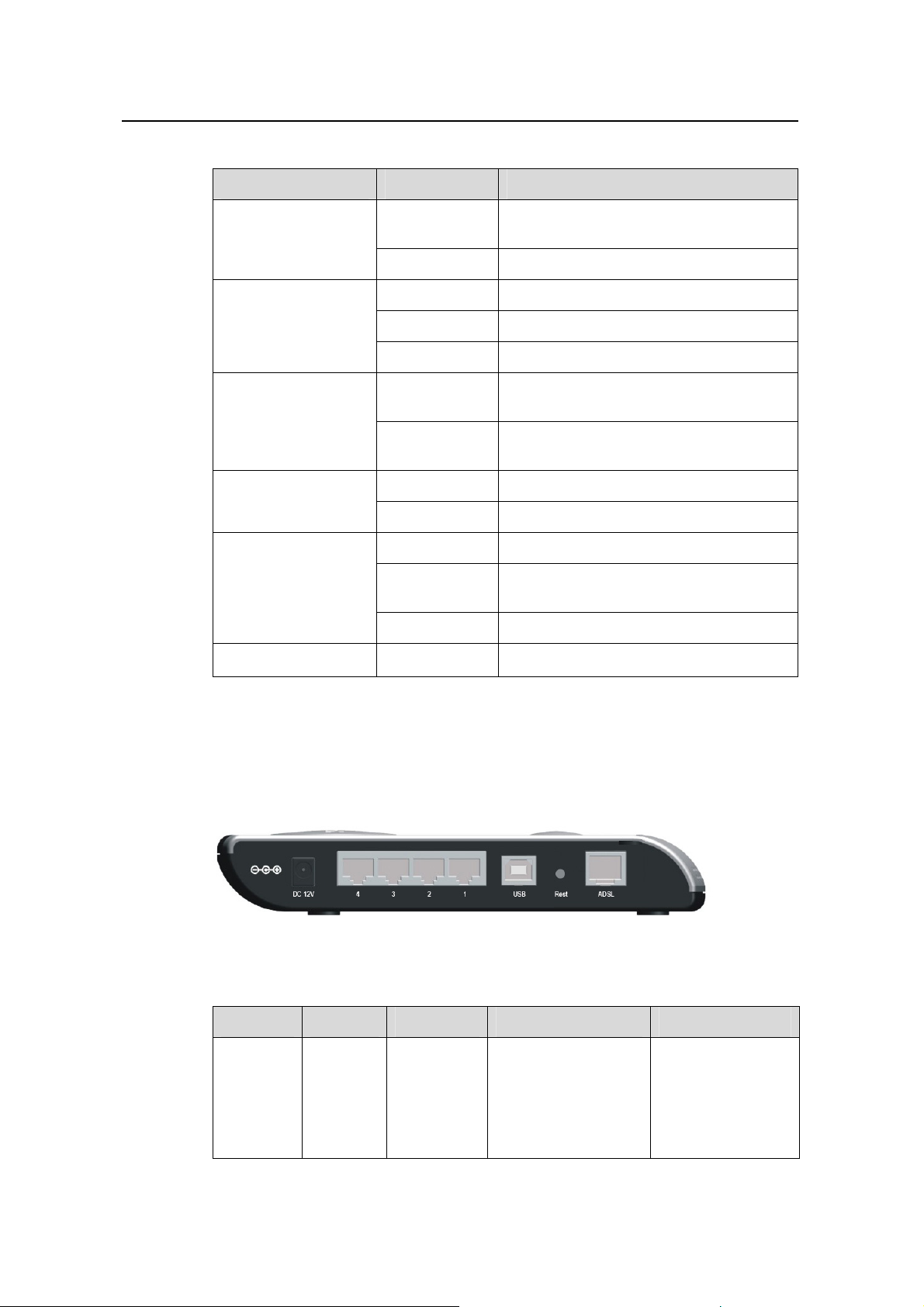
1.2.2 Rear Panel
All ports of the DR814Q, a power port, and a reset button are located on the rear p anel.
Figure 1-2 Rear view
Table 1-2 Description of the ports and reset button
Item Quantity Port Description Usage
Ethernet
port
4 RJ45
10/100Base-TX
10/100 Mbps
auto-negotiation
auto-MDI/MDIX
IEEE802.3/802.3u
Connect with the
Ethernet port of a
PC, Hub or switch.
2
Page 8

User Manual
Aolynk DR814Q ADSL2+ Broadband Router 1 Product Overview
Item Quantity Port Description Usage
USB port 1
ADSL port 1 RJ11
Power
port
Reset
button
1.3 Features
1
1
Series-B
Receptacle
—
—
USB 1.1
ANSI T1.413 Issue 2
ITU G.992.1 AnnexA
G.dmt
ITU G.992.2 G.lite
ITU G.992.3 ADSL2
ITU G.992.5 ADSL2+
—
—
Connect with the
USB port of a PC.
Connect with the
telephone jack on
the wall or the
ADSL port of a
splitter.
Connect with the
power adapter.
Restore factory
default settings
(press and hold
down the button for
at least five
seconds).
DR814Q performs excellent network connection, featuring:
z Asymmetrical data transmission technology with downstream speed of 20 Mbps
and upstream speed of 1 Mbps.
z Binding of an Ethernet port to a PVC, which enables you to access Internet
services through different LAN ports.
z NAT (network address translation) technology that allows all PCs on a network to
access the Internet sharing a single IP address.
z PPPoE dialup connection to the ISP.
z Capability of a DHCP (dynamic host configuration protocol) client to obtain a fixed
IP address from an ISP or a dynamically assi gned IP address.
z Capability of a DHCP server to assign IP addresses to host s in a LAN or configure
clients through the DHCP server.
z DNS relay that allows you to specify the IP address of an Ethernet port on the
DR814Q as a DNS server IP address of a PC.
z DHCP relay that allows one DHCP server available for multiple DHCP clients in
different network segments.
z ZIPB (zero installation PPP bridge), NAT, firewall, and IP filtering that secure your
LAN.
z UPnP (Universal plug-and-play) for LAN users to use all the functions provid ed by
UPnP-supported software (such as MSN) without any further configuration.
z IP routing, DNS (domain name system) configuration, and the services such as
the IP and DSL performance monitoring.
3
Page 9

User Manual
Aolynk DR814Q ADSL2+ Broadband Router 1 Product Overview
z Friendly built-in Web-based graphical user interface for ease of configuration and
management through common Web browsers.
4
Page 10

User Manual
Aolynk DR814Q ADSL2+ Broadband Router 2 Installation
2 Installation
2.1 Pac
On the assumption that you have a
sections describ
e how to set up the DR814Q and configure your PC.
cquired DSL services from your ISP, the following
king List
Unpack the shipping ca
Table 2-1 Packing list
Aolynk DR814Q ADSL2+ Broadband Router 1
Power adapter
Telephone cable
Ethernet cable
USB cable
Set of screw and anchor
Aolynk DR814Q ADSL2+ Broadband Router Quick S tart 1
CD including the user manual and driver
rton carefully and check the following items listed in Table 2-1.
Item Quantity
1
1
1
1
2
1
2.2 Prec
Warranty Card
Certificate of Quality
If anything is b
roken or missing, contact your agent for help.
1
1
autions
To guarantee normal operat ion and longevity of the DR814Q, it s installation site should
t the requirem
mee ents described below:
z Use the DR814Q indoors and keep it far away from the heat sources and
water/liquid.
5
Page 11
User Manual
Aolynk DR814Q ADSL2+ Broadband Router 2 Installation
z Keep the cabinet or desk stable enough to hold the DR814Q. Fix the DR814Q and
power adapt
z Reserve more than 10 cm (4 in.) of clearance around the DR814Q chassis for heat
er well on the wall when wall-mounting it.
dissipation.
z Keep the operation environment clean. Dust buildup on the chassis may result in
static absorption, reducing the life span and causing comm u
z Use an earthing system or lightning protection grounding different from that for the
power supply equipment and keep them as far as poss
z Keep the DR814Q far away from high-power radio launchers, radar launchers,
nication failure.
ible.
and equipment with high-frequency and high-current.
z ble indoors. Outdoor cabling is prohibited, to prevent the signal
Wire the port ca
port from damages that may be caused by overvoltage and overcurrent from
lightning strike.
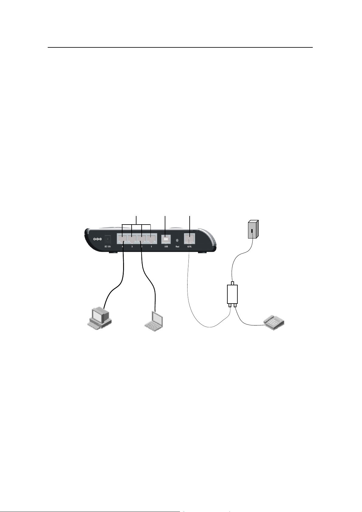
2.3 Device Connection
USB ADSL
LAN
LAN
USB ADSL
Telephone jack
Telephone jack
DR814Q
DR814Q
Line
Line
Splitter
Splitter
ADSL
ADSL
PC Notebook
PC Notebook
Figure 2-1 Connect the DR8
I.
Connect to an ADSL line
To c
onnect the DR814Q to an ADSL line, two options are available:
z end of the telephone cable to the ADSL port (similar to a common
Connect one
14Q
Phone
Phone
Telephone
Telephone
telephone port) on the DR814Q rear panel, and the other end to the telephon e jack
on the wall.
z and the
As shown in Figure 2-1, connect both the ADSL port on the DR814Q
telephone to a splitter, and then con
wall. It allows you to use the
telephone when you access the network.
nect the splitter to the telephone jack on the
6
Page 12
User Manual
Aolynk DR814Q ADSL2+ Broadband Router 2 Installation
II
. Connect to a PC or Ethernet
To conn
z The Ethernet ports of the DR814Q are auto-MDI/MDIX, so you can use the
ect the DR814Q to a PC or Ethernet, two options are available:
crossover or straight-through cable to connect your P
C, Hub, or switch to the
Ethernet port (one among LAN1 through LAN4) of the DR814Q.
Connect your PC to the DR814Q through the USB ports with a USB cable. It is
z
uitable for the PC without NIC to access the Internet.
s
Caution:
To use the USB port on the DR814Q, you must install the USB driver and configure
your PC (refer to section 8 “Appendix - USB Configuration” for detailed information).
I. Connect to the power adapter II
Attach one end of the power adapter to the DR814Q and the other end to the power
outlet. The DR814Q has no power switch, so it is powered on as soon as you plug the
power adapter into the power outlet.
Approximately one minute after the powe
the fr nel should b listed in Table 2-2.
ont pa e those
Table 2-2 Descr the LED state
iption of s
r-on of the DR814Q, the states of the LEDs on
LED State Description
Power Green
Link Green
Blinking eived.
—
—
Data is being transmitted and rec
Act
OFF No data transmission is present.
Green The Ethernet link is established.
LAN
Blinking
Data is being transmitted and received on the
Ethernet port.
7
Page 13

User Manual
Aolynk DR814Q ADSL2+ Broadband Router 3 Getting Started
3 Getting Started
3.1 Prer
I. S stem
II.
III.
The DR814Q offers a serie
can configure the DR814Q as needed. This chapter guides you to be familiar with the
Web configuration pages.
s of Web configuration pages as the way to manage it. You
equisite Tasks for Configuration
To configure the DR814Q thro
as the following.
y requirement s
z An Ethernet NIC (10Base-T
z A Web browser (Microsof
z TCP/IP protocol emplo
IP address of your PC
You must assign an IP address to your PC to make it in the same network segment as
the DR814Q before a
DR814Q Ethernet po
No proxy server
ccessing the configuration page. The default IP address of the
rt is 192.168.1.1. Refer to section 7 “Appendix - TCP/IP Protocol”.
ugh its built-in Web pages, you must configure your PC
or 10/100Base-T/TX) or a USB port
t Internet Explorer 5.5, Netscape 6.0 or later)
yed
3.2 Log
If your PC uses the proxy server to access the Internet, you must disabl
service.
1) Choose [Tool/Internet options] to open the [Internet option
2) Select the [Connections] tab and click <LAN settings…>.
Make sure the Use a proxy server option is not selected.
3)
s] window.
e the proxy
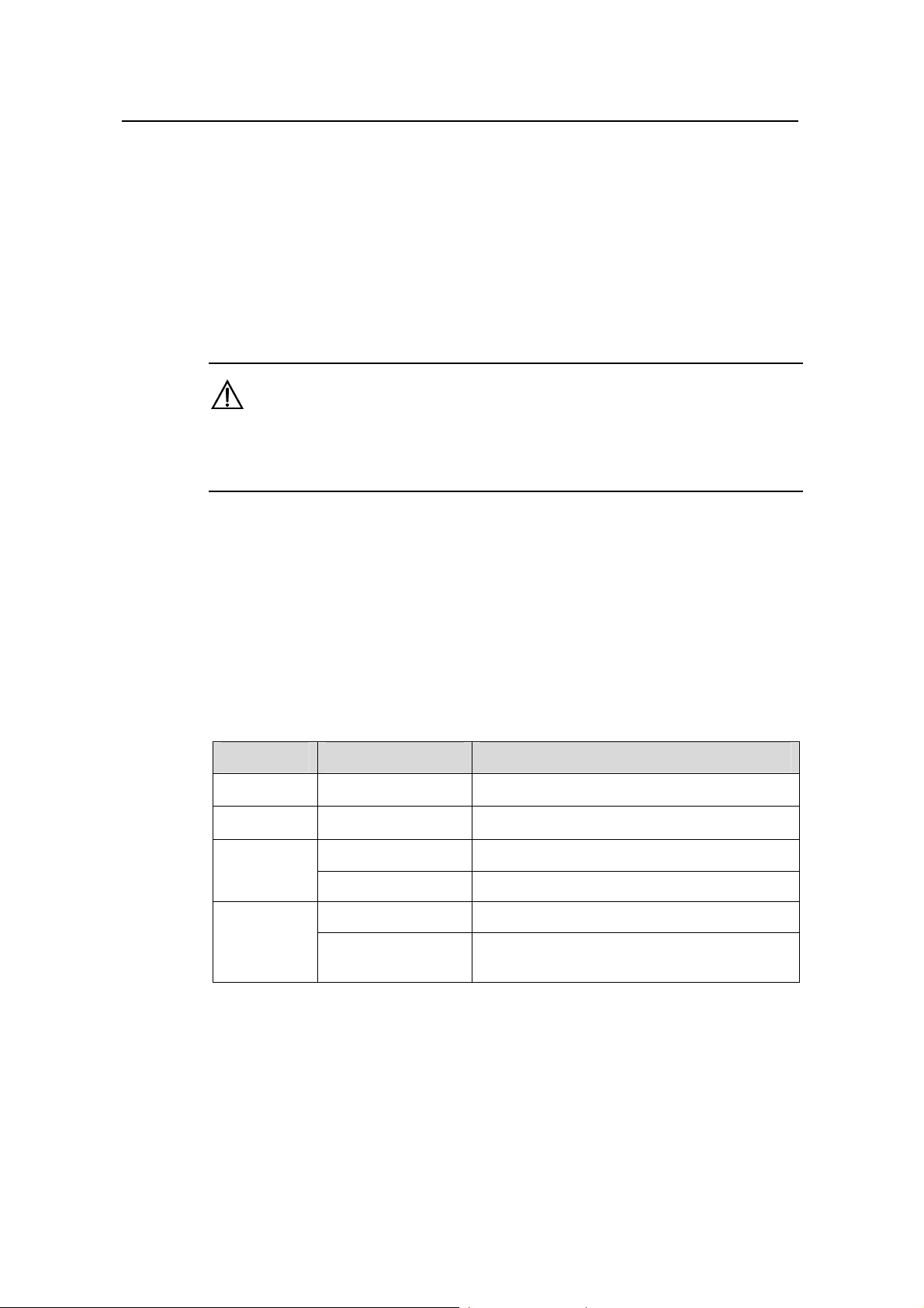
in
Run your Web browser and enter http://192.168.1.1 in the address bar. The login
dialog box appears as shown in Figure 3-1.
8
Page 14
User Manual
Aolynk DR814Q ADSL2+ Broadband Router 3 Getting Started
adminadmin
Figure 3-1 Login dialog box
If this is your first login, type the default user name and password admin, and then click
<OK> to enter the [Welcome] page as shown in Fig ure 3-2.
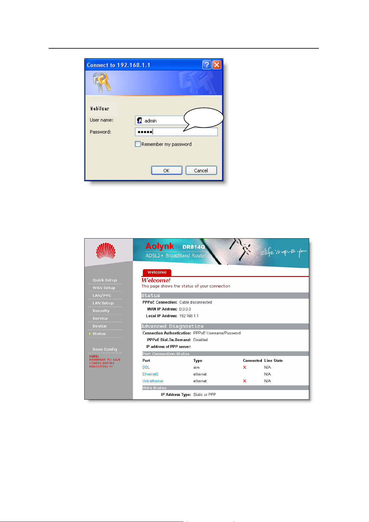
Figure 3-2 Welcome page
The left pane of the Web configuration page is the navigation bar and the right pane is
the parameter setting section, where, when clicking a navigation button in the
navigation bar, the co rresponding parameter settings will appear.
9
Page 15

User Manual
Aolynk DR814Q ADSL2+ Broadband Router 3 Getting Started
Note:
z To change the login password, refer to section 4.4.1 “Password” for detailed
information.
z If you receive an error message or the configuration page cannot be displayed, refer
to section 6.1 “DR814Q Troubleshooting” for detailed instructions.
3.3 Description of the Factory Default Settings
The DR814Q is configured with factory default settings for SOHO users.
The table below lists some of the most important default settings and the subsequent
chapters will cover all the features in detail. If you are familiar with network
configuration, review these settings to verify that they meet the requirements of your
network and follow the instructions to change them if necessary. If not, use the DR814Q
with the default settings.
Table 3-1 Description of the factory default settings
Item
Default settings
Y ou can log into the Web configuration
Administrator:
Default user
name/password
admin/admin
Common user:
user/user
page as an administrator or a common
user. Different operation rights are
available for different login users.
Refer to 4.4.1 “Password” for detailed
information.
IP address of the
LAN port
Assigned static IP
address:
192.168.1.1
Subnet mask:
255.255.255.0
This is the IP address of the DR814Q
LAN port which connects the DR814Q
to your Ethernet network. Generally,
there is no need to change this
address.
The DR814Q provides a pool of
DHCP server
DHCP
(dynamic host
configuration
protocol)
enabled with the
following pool of
addresses:
192.168.1.2 to
192.168.1.51
private IP addresses for dynamic
assignment to PCs in the LAN. To use
this service, you must configure your
PC to obtain an IP address
dynamically. Refer to section 7.2.1
“Specifying to Obtain an IP Address
Automatically”.
Description
NAT (network
address translation)
DSL mode
NAT enabled
Multimode
10
Your PC’s private IP address is
translated to the public IP address
whenever it accesses the Internet.
Refer to section 5.2.1 IV. “NAT
configuration” for detailed information.
Applicable to multiple standard DSL
line modes.
Page 16
User Manual
Aolynk DR814Q ADSL2+ Broadband Router 4 Web-based Basic Configuration
4 Web-based Basic Configuration
4.1 Qui
This chapter describes the ba
to implement its basic functions. For details of advanced configuration, refer to section
5 “Advanced C
onfiguration”.
sic configuration pages of the DR814Q for SOHO users
ck Setup
Click [Quick Setup] in the navigation bar to en
can perform
login type
I. PPPoE
some simple settings to access the Internet quickly. Here, two common
s are available: PPPoE and DHCP.
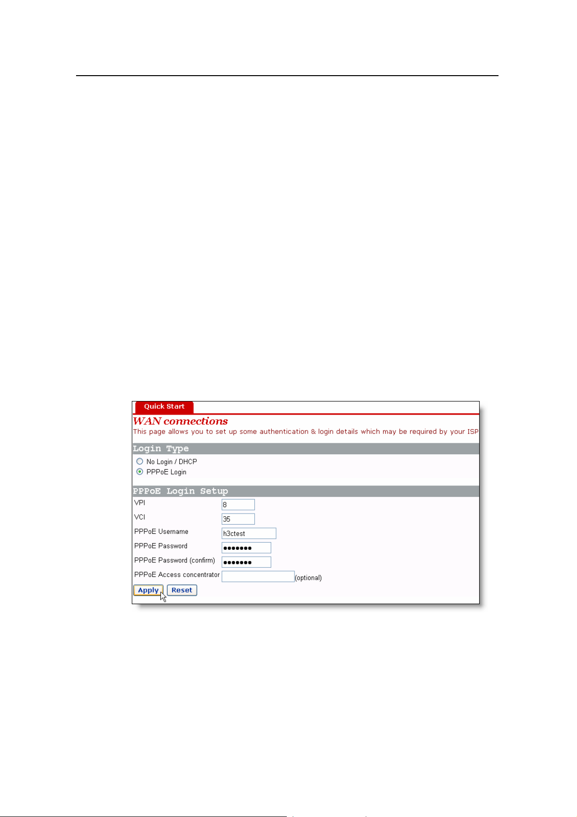
ter the [Quick Start] page on which you
Figure 4-1 Quick Setup – PPPoE Login
The default login type on the page is PPPoE. This type requires you to type in the V
and VCI values, PPPoE user name and PPPoE password specified by your ISP, and
repeat the password for confirmation in the [PPPoE Password (confirm)] text box.
11
PI
Page 17
User Manual
Aolynk DR814Q ADSL2+ Broadband Router 4 Web-based Basic Configuration
When the
server identifier through which the PPPoE client accesses in the [PPPoE Access
concentrator] text box.
Click <Apply> after the configuration is complete.
re are multiple PPPoE servers in the network, you can specify the PPPoE
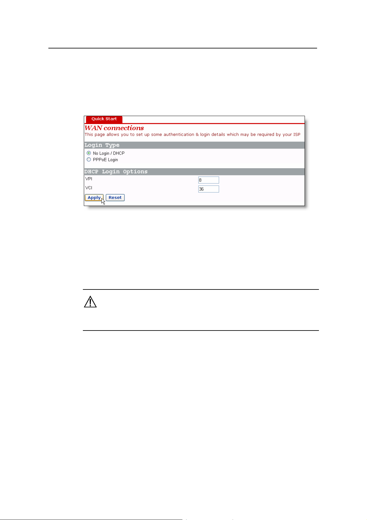
II. DHCP
Figure 4-2 Quick Setup – No Login/DHCP
you can obtain IP addresses from your ISP’s DHCP server automatically, select the
If
No Login/
and VCI values s
Click <Apply> after the configuration is complete.
Do not set the same VPI and VCI values for DHCP and PPPoE login types.
DHCP option on the [Quick Start] page (see Figure 4-1) and type in the VPI
Caution:
4.2 WAN Setup
Click [WAN Setup] in the navigation bar to enter the corresponding pag e on which three
tabs are available: WAN, DNS Relay, and DDNS. Click the desired tab to enter its
configuration page.
4.2.1 WAN
pecified by your ISP on the page (see Figure 4-2).
This page allows you to set WAN connections in detail, or to modify the service
attributes. You can access the Internet normally only when these attributes are set
correctly.
12
Page 18
User Manual
Aolynk DR814Q ADSL2+ Broadband Router 4 Web-based Basic Configuration
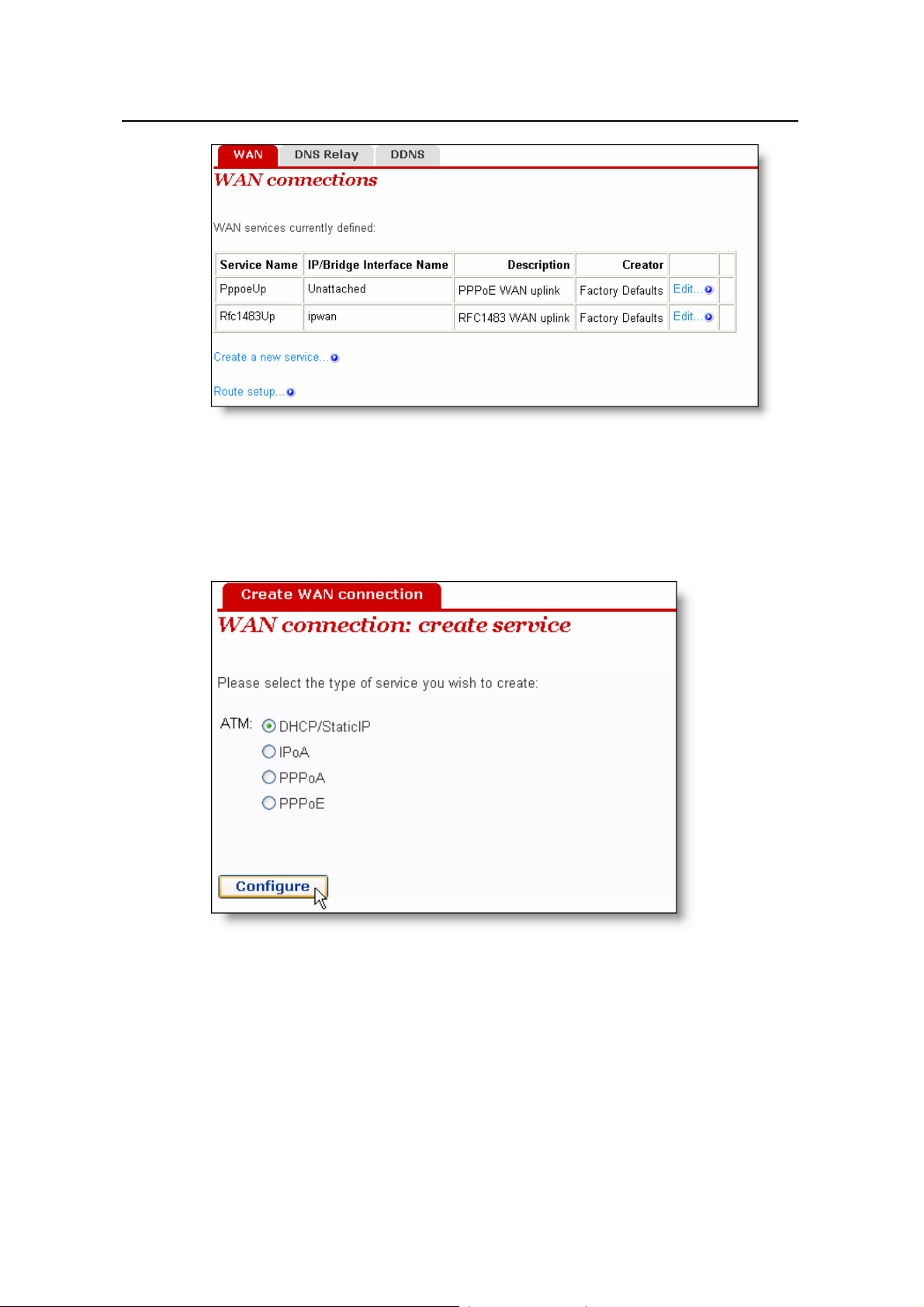
Figure 4-3 WAN
I. Create a new service
To create a new servi ce, click <Create a new se rvice…> to enter the [W A N connection:
create service] page (see Figure 4-4).
Figure 4-4 Create a WAN service
This page provides four modes for WAN connection: DHCP/StaticIP, IPoA, PPPoA and
PPPoE. The following introduces their configurations respectively.
1) DHCP/Static IP
The IP address in this mode can be manually specified or automatically assigned by
your ISP. The former requires you to manually specify the DNS server address on the
[DNS Relay] page. For details, refer to section 4.2.2 “DNS Relay”.
13
Page 19
User Manual
Aolynk DR814Q ADSL2+ Broadband Router 4 Web-based Basic Configuration
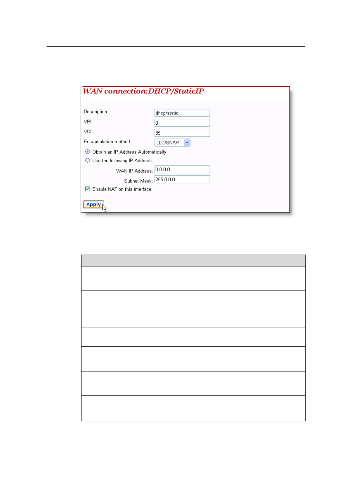
To create a DHCP/S tatic IP W AN connection, select the DHCP/StaticIP option from the
ATM mode list (see Figure 4-4), and then click <Configure> to enter the page (see
Figure 4-5).
Figure 4-5 DHCP/Static IP
Table 4-1 Description of the DHCP/Static IP items
Item Description
Description Type in the distinct ive description on this service.
VPI Type in the VPI value provided by your ISP.
VCI Type in the VCI value provided by your ISP.
Encapsulation
method
Obtain an IP Address
Automatically
Use the following IP
Address
Select the packet encapsulation method according to your
ISP, LLC/SNAP or VcMux, from the drop-down lastly/SNAP
is usually selected.
Select this option to obtain an IP address from your ISP’s
DHCP server automatically.
Select this option if you have the static IP address provided
by your ISP. You need also provide the IP address and
subnet mask.
WAN IP Address Type in the static IP address provided by your ISP.
Subnet Mask Type in the subnet mask provided by your ISP.
Enable NAT on this
interface
Select this check box to enable NAT. With it, SOHO users
can make multiple hosts access network via a public IP
address.
Click <Apply> after the configuration is complete.
14
Page 20
User Manual
Aolynk DR814Q ADSL2+ Broadband Router 4 Web-based Basic Configuration
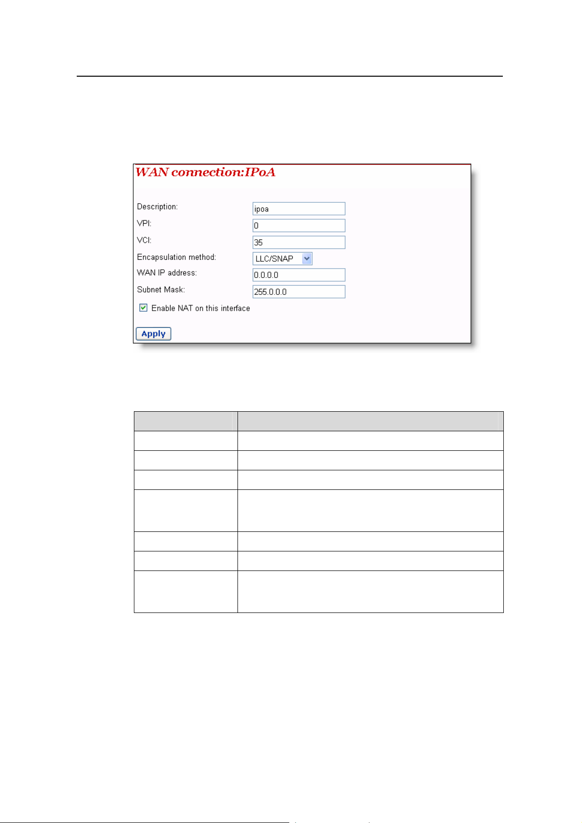
2) IPoA
IPoA allows IP packets directly over the ADSL physical link at high tran smission rate.
T o create a n IPoA WA N connection, select the IPoA option from the ATM mode list (see
Figure 4-4), and then click <Configure> to enter the page as below.
Figure 4-6 IPoA
Table 4-2 Description of the IPoA items
Item Description
Description Type in the distinct ive description on this service.
VPI Type in the VPI value provided by your ISP.
VCI Type in the VCI value provided by your ISP.
Encapsulation
method
Select the packet encapsulation method according to your
ISP, LLC/SNAP or VcMux, from the drop-down lastly/SNAP
is usually selected.
WAN IP Address Type in the static IP address provided by your ISP.
Subnet Mask Type in the subnet mask provided by your ISP.
Enable NAT on this
interface
Select this check box to enable NAT. With it, SOHO users
can make multiple hosts access network via a public IP
address.
Click <Apply> after the configuration is complete.
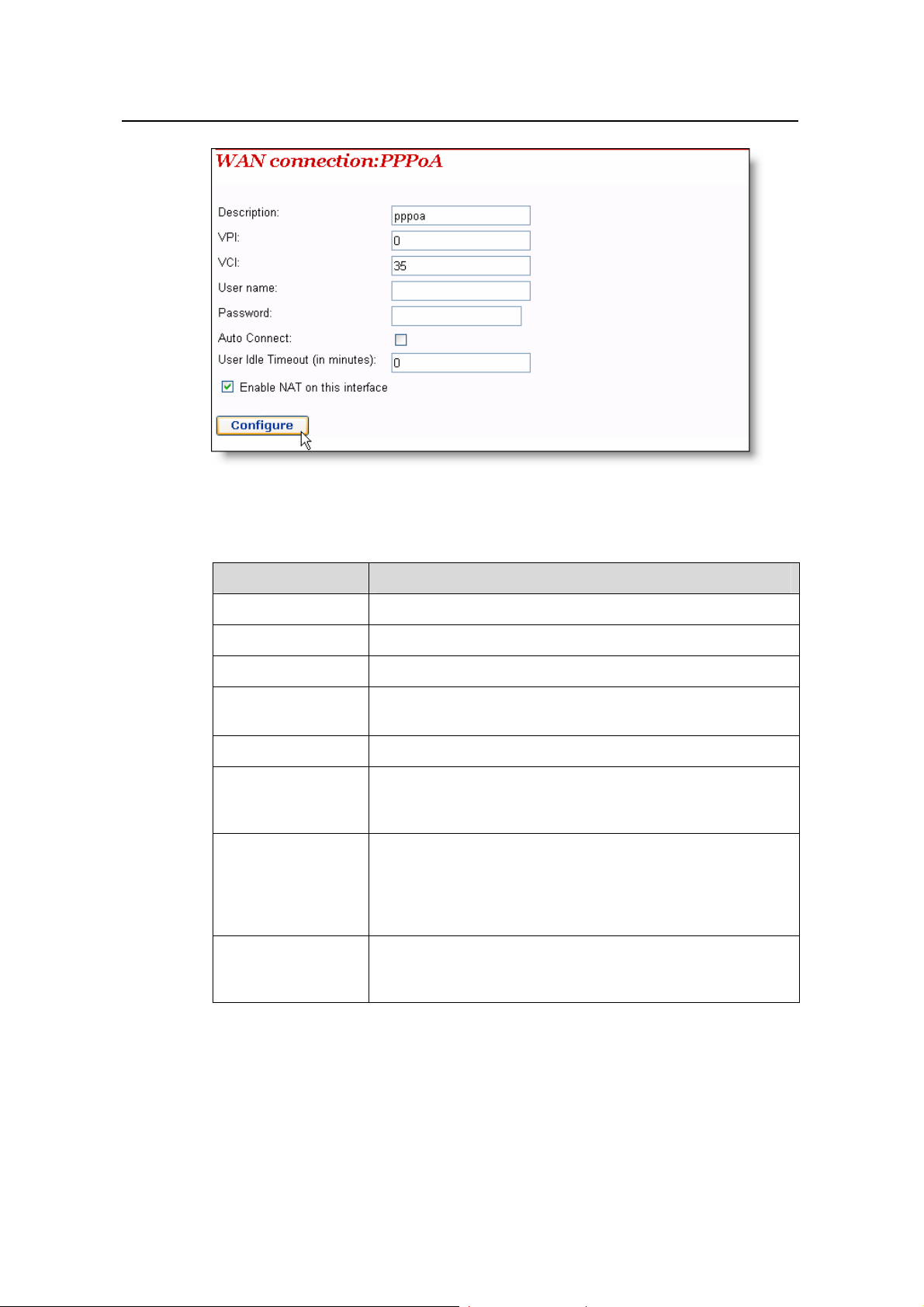
3) PPPoA
To create a PPPoA WAN connection, select the PPPoA option from the ATM mode list
(see Figure 4-4), and then click <Configure> to enter the page as belo w.
15
Page 21
User Manual
Aolynk DR814Q ADSL2+ Broadband Router 4 Web-based Basic Configuration
Figure 4-7 PPPoA
Table 4-3 Description of PPPoA items
Item Description
Description Type in the distinct ive description on this service.
VPI Type in the VPI value provided by your ISP.
VCI Type in the VCI value provided by your ISP.
User nameUser
name
Type in the user name prov ided by your ISP.
Password Type in the password provided by your ISP.
If this check box is selected, the device automatically
Auto Connect
performs the dialup connection again in response to a LAN
access request when the network is disconnected.
Type in the auto-disconnect idle time. Network connection is
disconnected automatically in the case of no data
User Idle Timeout
transmission within the set time. This is suitable for
time-based network accounting. If the time is set to 0, it
indicates that the connection is never disconnected.
Enable NAT on this
interface
Select this check box to enable NAT. With it, SOHO users
can make multiple hosts access network via a public IP
address.
Click <Configure> after the configuration is complete.
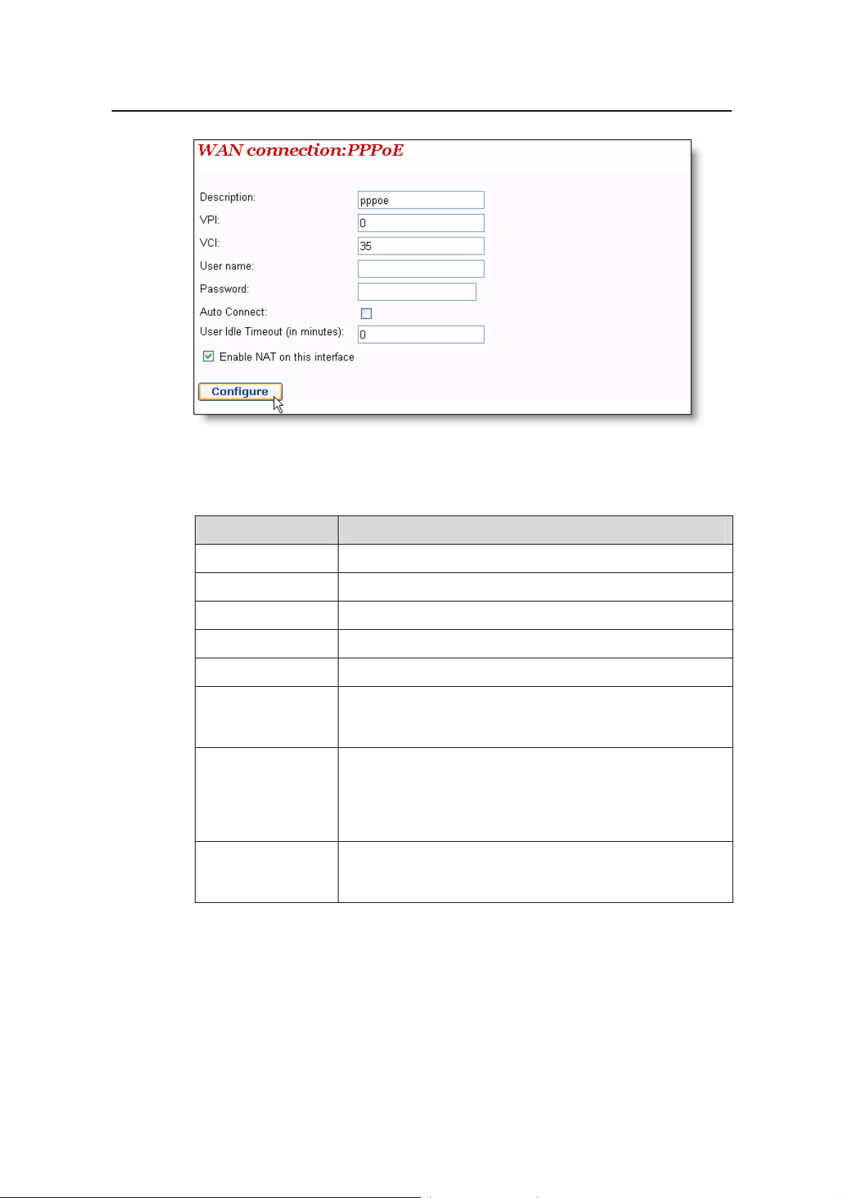
4) PPPoE
To create a PPPoA WAN connection, select the PPPoA option from the ATM mode list
(see Figure 4-4), and then click <Configure> to enter the page as belo w.
16
Page 22
User Manual
Aolynk DR814Q ADSL2+ Broadband Router 4 Web-based Basic Configuration
Figure 4-8 PPPoE
Table 4-4 Description of PPPoE items
Item Description
Description Type in the distinct ive description on this service.
VPI Type in the VPI value provided by your ISP.
VCI Type in the VCI value provided by your ISP.
User name Type in the user name pro v ided by your ISP.
Password Type in the password provided by your ISP.
If this check box is selected, the device automatically
Auto Connect
performs the dialup connection again in response to a LAN
access request when the network is disconnected.
Type in the auto-disconnect idle time. Network connection is
disconnected automatically in the case of no data
User Idle Timeout
transmission within the set time. This is suitable for
time-based network accounting. If the time is set to 0, it
indicates that the connection is never disconnected.
Enable NAT on this
interface
Select this check box to enable NAT. With it, SOHO users
can make multiple hosts access network via a public IP
address.
Click <Configure> after the configuration is complete.
17
Page 23
User Manual
Aolynk DR814Q ADSL2+ Broadband Router 4 Web-based Basic Configuration
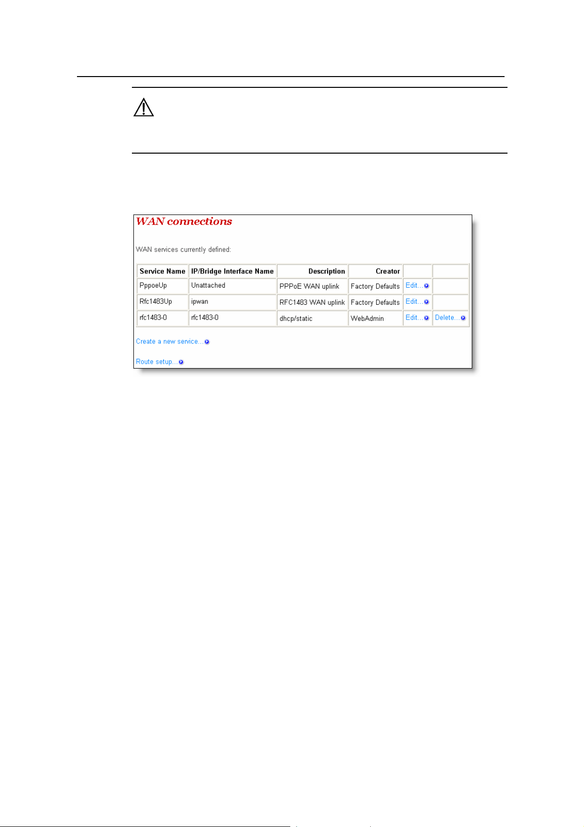
Caution:
Do not set the same VPI and VCI values for all services.
As shown in Figure 4-9, the service set up successfully will be added into the WAN
service list.
Figure 4-9 WAN service list
II. Edit a WAN service
To modify a service or perform advanced configuration, click the corresponding
<Edit…> to enter the page. If necessary, modify the related values and then click
<Change>.For details of the ATM Channel parameter configuration, refer to section 5.1
II. “QoS configuration”.
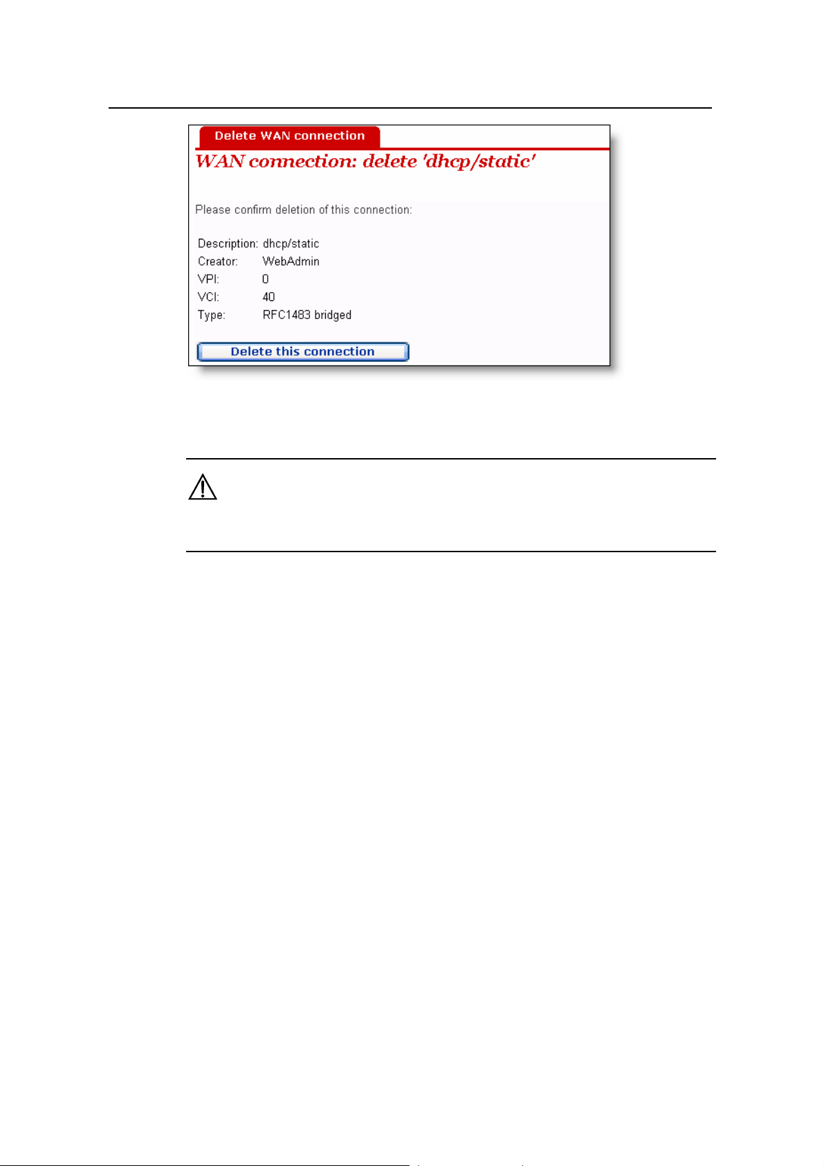
III. Delete a WAN service
To delete an existing WAN service, click the corresponding <Delete…> button to enter
the page, and then click <Delete this connection>.
18
Page 24
User Manual
Aolynk DR814Q ADSL2+ Broadband Router 4 Web-based Basic Configuration
Figure 4-10 Delete a WAN connection
Caution:
The first two items in the WAN service list are default services and cannot be deleted.
4.2.2 DNS Relay
The DR814Q has the DNS relay function. Generally, the DNS server addre ss obt ained
by your PC through DHCP is the IP address of the LAN port. You can also specify the
DNS server address on your PC as the IP address of the LAN port. The DR814Q
forwards the DNS query sent by your PC to the DNS server set on the DR814Q.
The configuration pages below are used to set the DNS server list. The DNS que ry sent
by your PC is forwarded to the DNS server in the existing list. When your ISP cha nge s
the DNS server or you modify the connected ISP, there is no need to modify the IP
address of the DNS server on your PC.
19
Page 25
User Manual
Aolynk DR814Q ADSL2+ Broadband Router 4 Web-based Basic Configuration
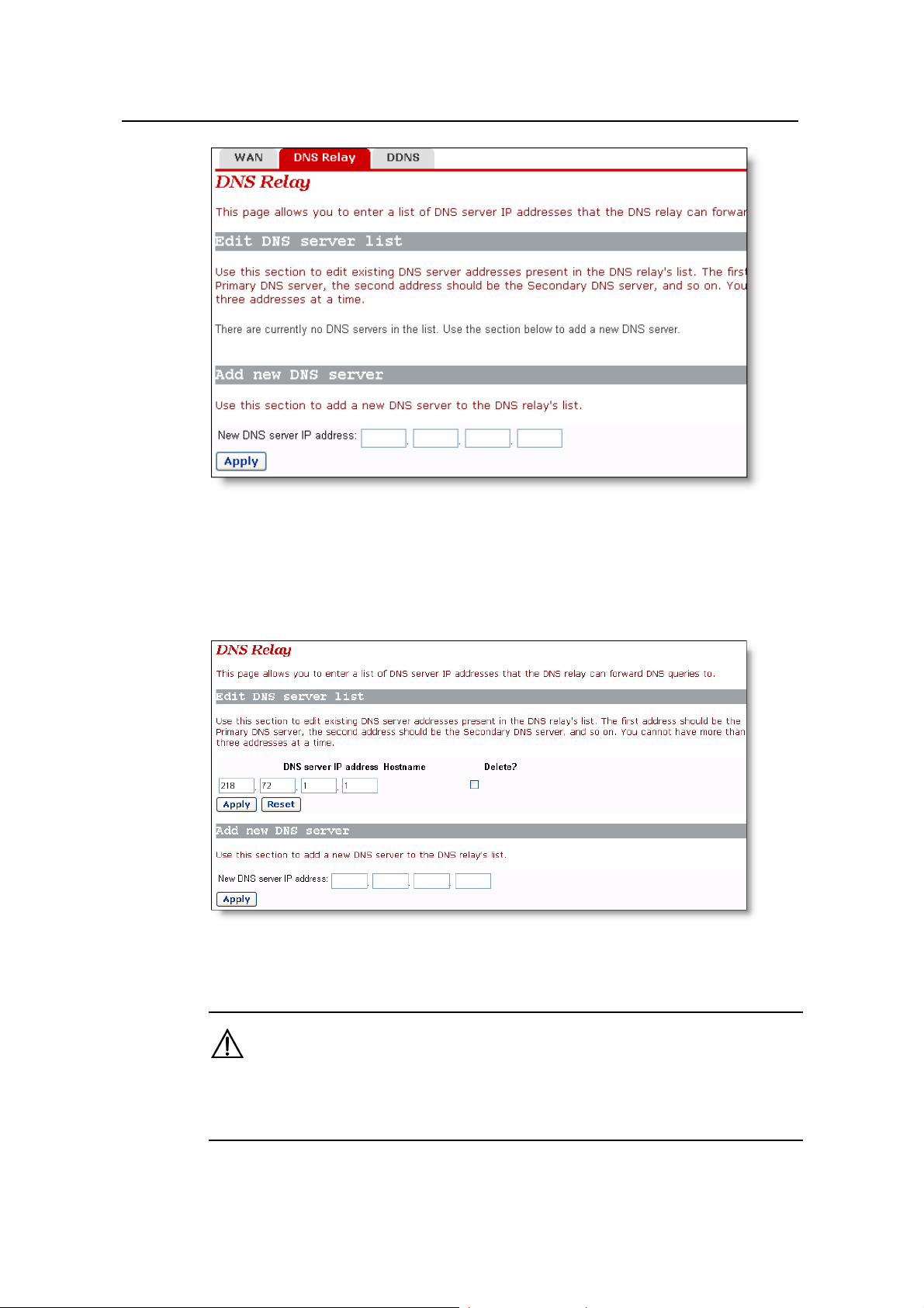
Figure 4-11 DNS Relay (1)
To create a new DNS server, type in its IP address, suppose 218.72.1.1, in the [New
DNS server IP address] field, and then click <Apply>. This address will be added to the
list of the DNS server IP address (see Figure 4-12).
Figure 4-12 DNS Relay (2)
Caution:
In the list of DNS server IP addresses, the first address should be for the primary DNS
server, the secon d for the seco ndary DNS server, and so on.
20
Page 26
User Manual
Aolynk DR814Q ADSL2+ Broadband Router 4 Web-based Basic Configuration
To modify the IP address of the DNS server in the list, modify it directly in the field and
then click <Apply>.
To delete the existing DNS server, select the corresponding [Delete?] check box and
then click <Apply>.
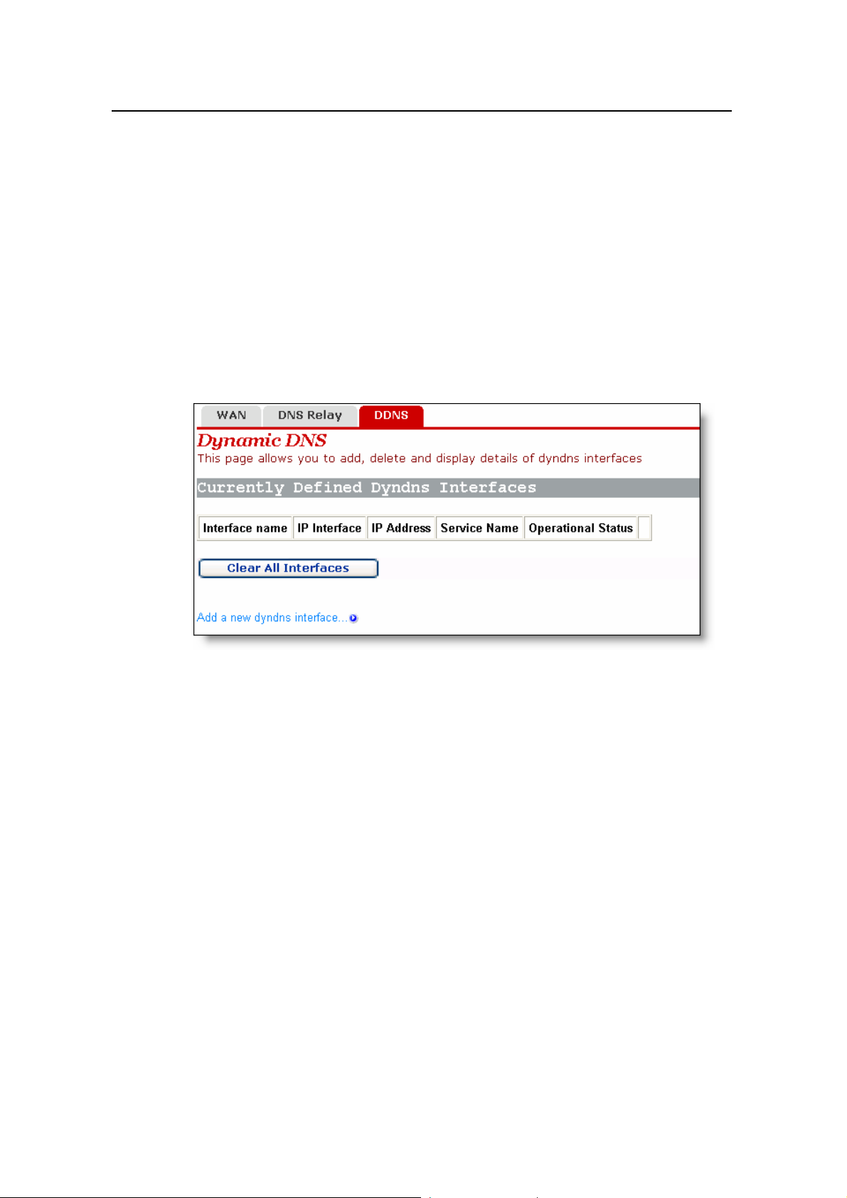
4.2.3 DDNS
Dynamic Domain Name Service (DDNS). By way of PPPoE or static IP, the IP address
that the WAN port obtained is unfixed, making it inconvenient for the Internet users to
access the LAN server. DDNS solves this problem. After you set the DDNS function,
the DR814Q update the mapping between the domain name and the IP address
automatically , ensuring the Internet users to access the LAN through the domai n name.
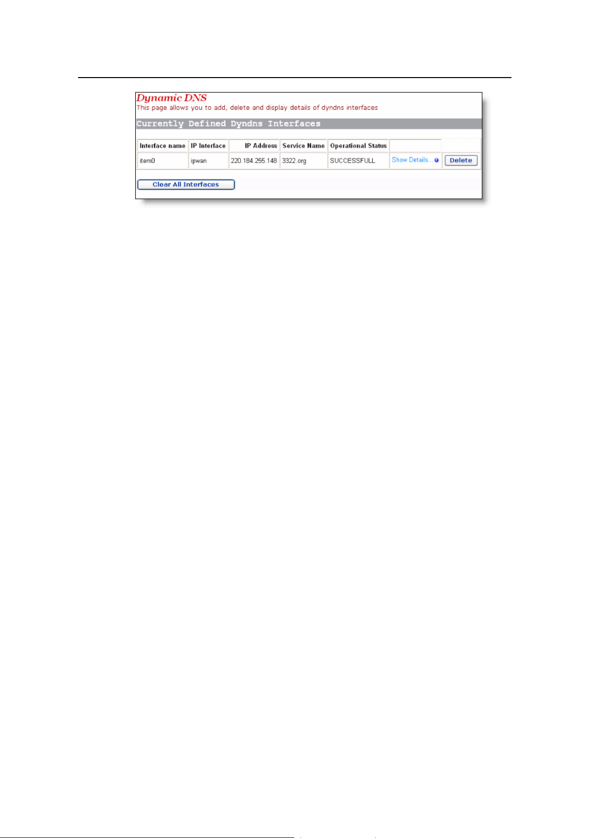
Figure 4-13 Dynamic DNS configuration (1)
Click <Add a new dyndns interface…> to enter the DDNS configuration page (see
Figure 4-14).
21
Page 27
User Manual
Aolynk DR814Q ADSL2+ Broadband Router 4 Web-based Basic Configuration
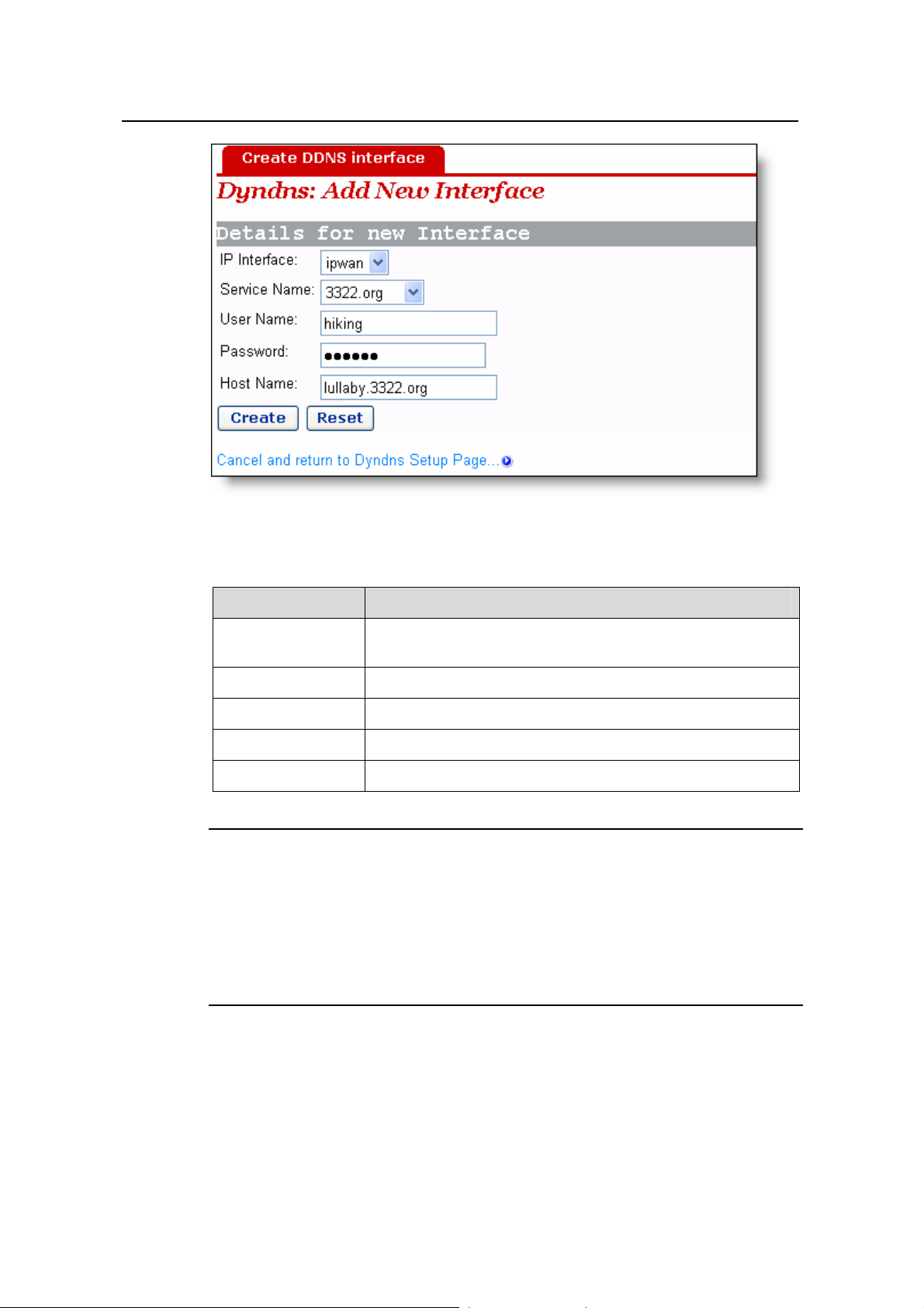
Figure 4-14 Dynamic DNS configuration (2)
Table 4-5 Description of the DDNS items
Item Description
IP interface
Service Name Select the web site where to obtain the DDNS service.
User Name Type in the user name you register with the DDNS server.
Password Type in the password you register with the DDNS server.
Host Name Type in the domain name you apply from the DDNS server.
Select the interface on which you want to enable the DDNS
function.
Note:
As the client tool of the DDNS service, the DDNS function must cooperate with the
DDNS server. Visit www.3322.org, www.dyndns.org or www.tzo.com to apply for a
domain name before you enable the DDNS function. After you complete the DDNS
settings on the DR814Q, the mapping between the domain name and the IP address of
the WAN port is established.
Example: If you have applied for the domain name lullaby from www.3322.org, see
Figure 4-14 for the settings to make the mapping between the domain name and the IP
address of the WAN port o n the DR81 4Q. C lick <Create> a nd you can vie w the DDNS
configurations as below .
22
Page 28
User Manual
Aolynk DR814Q ADSL2+ Broadband Router 4 Web-based Basic Configuration
Figure 4-15 DDNS configuration succeeds
To delete the DDNS configuration, click <Delete >. To clear all the DDNS configuration,
click <Clear All Interfaces>. To view the detailed configuration of the current DDNS
interface, click <Show Details…>.
4.3 LAN Setup
Click [LAN Setup] in the navigation bar to enter the corresponding page where three
tabs are available: LAN, DHCP Server, and DHCP Relay. Click any tab to enter your
desired configuration page.
4.3.1 LAN
This page allows you to set attribute values for the Ethernet port and to configure virtual
interfaces.
23
Page 29
User Manual
Aolynk DR814Q ADSL2+ Broadband Router 4 Web-based Basic Configuration
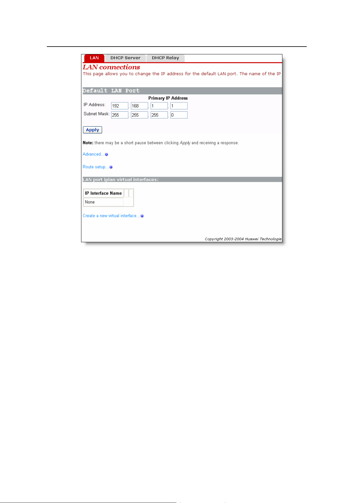
Figure 4-16 LAN connections
I. Set a LAN port
To change the IP address of the LAN port, type in the IP address and/or subnet mask
directly in the corresponding field, and then click <Ap ply>.For related introduction to the
IP address, refer to section 9 “Appendix - IP Address and Subnet Mask”
To perform advanced configuration on th e attribute of LAN port, click <Advanced…> to
enter the [Edit iplan] page as shown in Figure 4-17.If necessary, modify the values of
options and click <Change>.
24
Page 30
User Manual
Aolynk DR814Q ADSL2+ Broadband Router 4 Web-based Basic Configuration
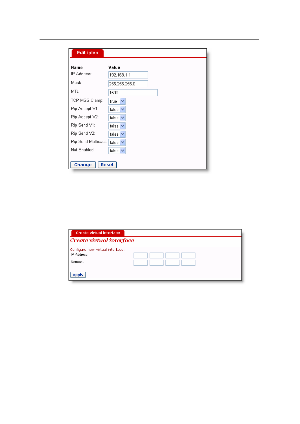
Figure 4-17 Modify the iplan interface
II. Create a new virtual interface
To create a new virtual interface, click <Create a new virtual interface…> on the [LAN
connections] page (see Figure 4-16) to enter the page as below.
Figure 4-18 Create a virtual interface
Type in the IP address and subnet mask (you cannot configure the IP address of the
virtual interface and that of the LAN port to be in the same subnet) and click <Apply>.
The information on this virtual interface is displayed on the page as below.
25
Page 31

User Manual
Aolynk DR814Q ADSL2+ Broadband Router 4 Web-based Basic Configuration
Figure 4-19 Virtual interface
The created virtual interface can be used for DMZ configuration. For details, refer to
section 5.3 "DMZ Configuration”.
To modify the information on the current virtual interface or perform advanced
configuration, click the corresponding <Edit…> button to enter the page. If necessary,
modify the values of options and click <Change>.
To delete the current virtual interface, click the corresponding <Delete…> button to
enter the page, and then click <Delete this connection…>.
4.3.2 DHCP Server
The DR814Q can act as a DHCP server to automatically assign IP addresses within a
certain range to any PC running in the LAN.
Figure 4-20 DHCP Server
I. Enable/disable the DHCP server
If the DHCP server is disabled currently, you can click <Enable> to enable it.
Conversely, you can also click <Disable> to disable the DHCP server.
26
Page 32

User Manual
Aolynk DR814Q ADSL2+ Broadband Router 4 Web-based Basic Configuration
II. Set a DHCP server
The enabled DHCP server can assign the IP addresses, according to the defined
address range on this page, to the DHCP client sending a request. It is recommended
that you select the [Use a default range] check box to assign a suitable default IP
address pool for the current subnet.
If necessary, you can also set the DHCP address range manually. In this case, do not
select the [Use a default range] check box (by removi ng t he ti ck). Type in the st a rt and
end IP addresses in the corresponding fields, and the n click <OK>.
If necessary , you ca n type in commonly used DNS suf fixes such as google.com in the
[Local domain name] text box. Thus, you can access the Google homepage by entering
http://www/ in the Web browser. Small and medium-sized enterprises can also set
their own DNS suffixes here while home users need not.
4.3.3 DHCP Relay
The DR814Q has the DHCP relay function to transmit packets between the DHCP
client and server in different network segments, thereby making the DHCP client on
multiple networks use the DHCP server across these segments.
27
Page 33
User Manual
Aolynk DR814Q ADSL2+ Broadband Router 4 Web-based Basic Configuration
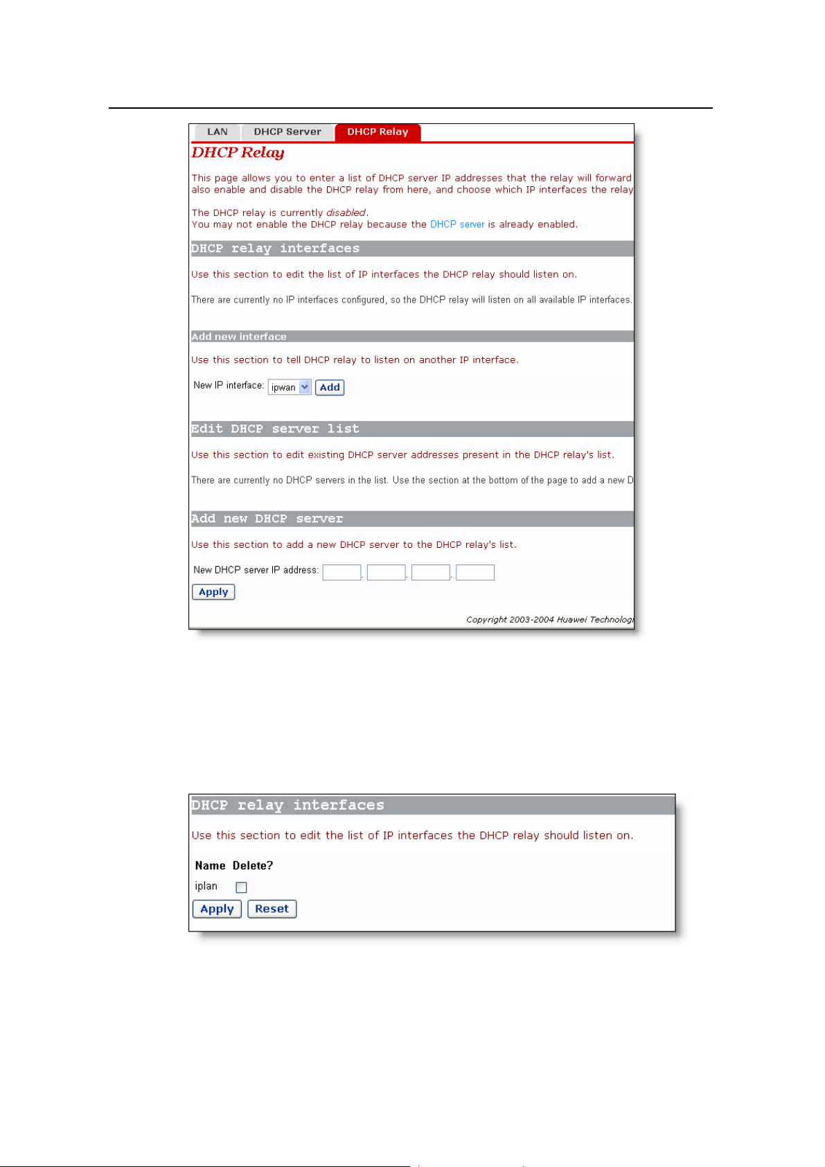
Figure 4-21 DHCP Relay page
I. Specify a DHCP relay interface
On the [DHCP Relay] page (see Figure 4-21), select an interface (suppo se iplan) from
the [New IP interface] drop-down list to apply the DHCP relay function, and then click
<Add>. This interface will appear on the page as below.
Figure 4-22 New IP interface
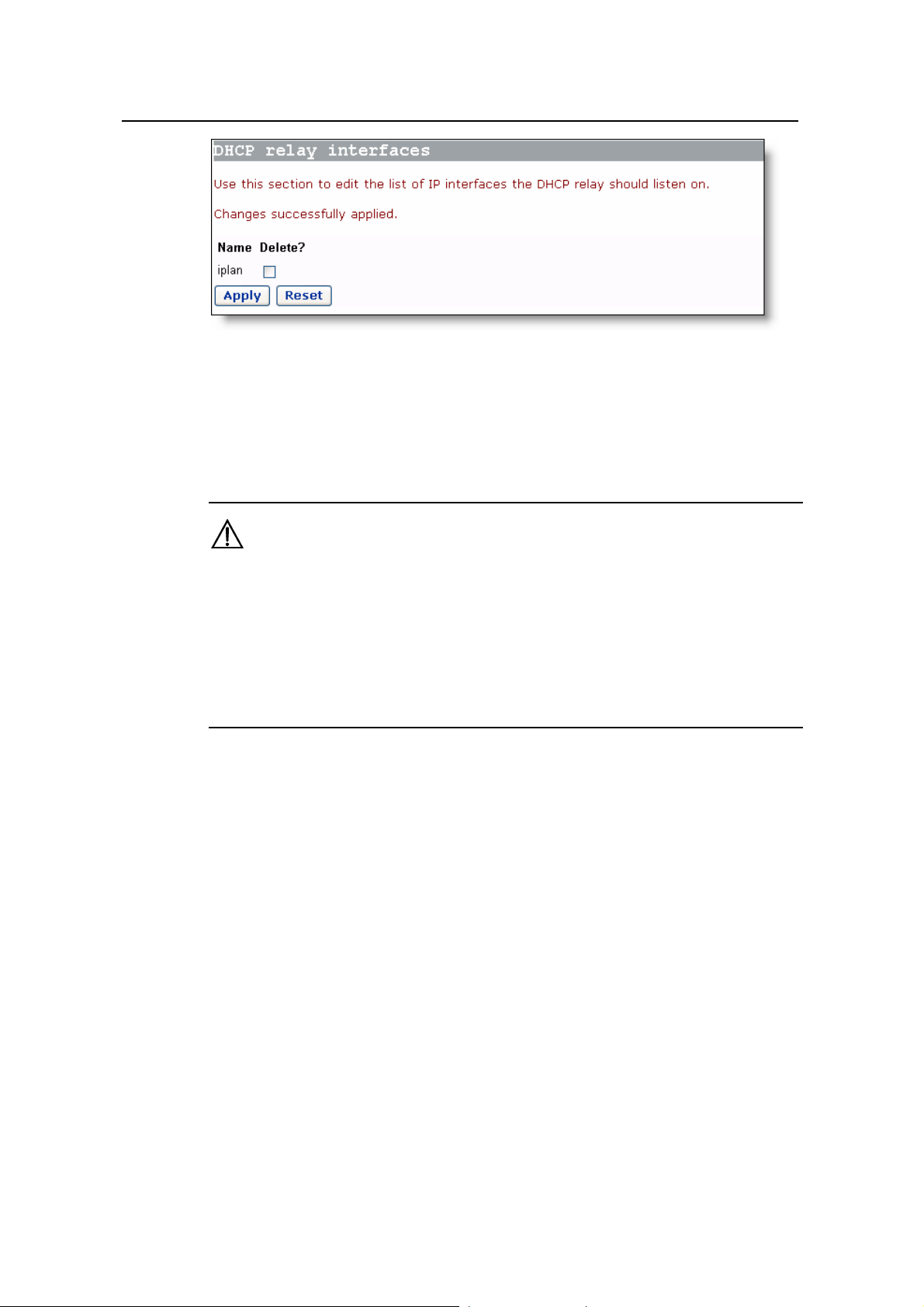
Click <Apply> in Figure 4-22 to apply this configuration, and the “Changes successfully
applied” information appear on the page as below.
28
Page 34
User Manual
Aolynk DR814Q ADSL2+ Broadband Router 4 Web-based Basic Configuration
Figure 4-23 The applied new IP interface
Follow the above instructions to specify other interfaces.
To delete this interface, select the corresponding [Delete?] check box and click
<Apply>.
Caution:
z You should configure two interfaces (sending and receiving packets respectively) of
DHCP relay in pair. For example, to set the host connected to the LAN port to
communicate with the DHCP server on the WAN side, you need to configure the
iplan and ipwan to be the DHCP relay interfaces concurrently.
z If no interface is specified, the DR814Q enables the DHCP relay function on all
interfaces by default.
II. Set a DHCP server
T o add a DHCP server , type in the IP address (suppose 20.2.0.100) of the DHCP server
in the [New DHCP server IP address] field (see Figure 4-21). This address will be
added to the list of DHCP server IP addresses as below.
29
Page 35

User Manual
Aolynk DR814Q ADSL2+ Broadband Router 4 Web-based Basic Configuration
Figure 4-24 Set a DHCP server
To modify the IP addre ss of the DHCP server in the list, modify it directly in the field and
then click <Apply>.
To delete the existing DHCP server, select the corresponding [Delete?] check box and
then click <Apply>.
III. Enable/disable DHCP relay
You need to enable the DHCP relay function after the configuration is complete. The
functions of DHCP server and DHCP relay of the DR814Q cannot be enabled
concurrently . By default, you cannot enable the DHCP relay because the DHCP server
is already enabled. The prompt is display as shown in Figure 4-21.
Click <DHCP Server> on the above page (see Figure 4-24) to enter the DHCP server
page, click <Disable> and thus <Enable> appea rs on the pag e (see Figure 4-25). If the
DHCP relay is disabled currently, you can click <Enable> to enable it. Conversely, click
<Disable> to disable it.
Figure 4-25 Enable/disable the DHCP relay
30
Page 36

User Manual
Aolynk DR814Q ADSL2+ Broadband Router 4 Web-based Basic Configuration
Caution:
To ensure the DHCP relay to be effective, you need to disable NAT between the
specified interface and the interface corresponding to the network where the DHCP
server resides. For example, to specify the host connected to the LAN port to
communicate with the DHCP server on the ipwan interface, you must disable NAT
between the internal interface (iplan) and the external interface (ipwan).
4.4 Device
Click [Device] in the navigation bar to enter the corresponding page whe re five tabs are
available: Password, Remote, Restart, Backup and Upgrade. Click any tab to enter
your desired configuration page.
4.4.1 Password
You can access log into the Web configuration page of DR814Q via two user name:
admin and user. The administrato r has the maximum rights while the common user can
only access part of the configuration pages. Only the administrator can enter the
following [Password] page to change the login passwords for two users. The common
user can only change its own password.
Figure 4-26 Change the password
By default, admin and user are the passwords for administrator and common user
respectively.
31
Page 37
User Manual
Aolynk DR814Q ADSL2+ Broadband Router 4 Web-based Basic Configuration
To change the password, type in the related information in the [Old Password], [New
Password] and [Confirm Password] text boxes, and then click <Apply>.
4.4.2 Remote Access
If remote access is enabled, you can view the current configuration page and manage
the DR814Q remotely.
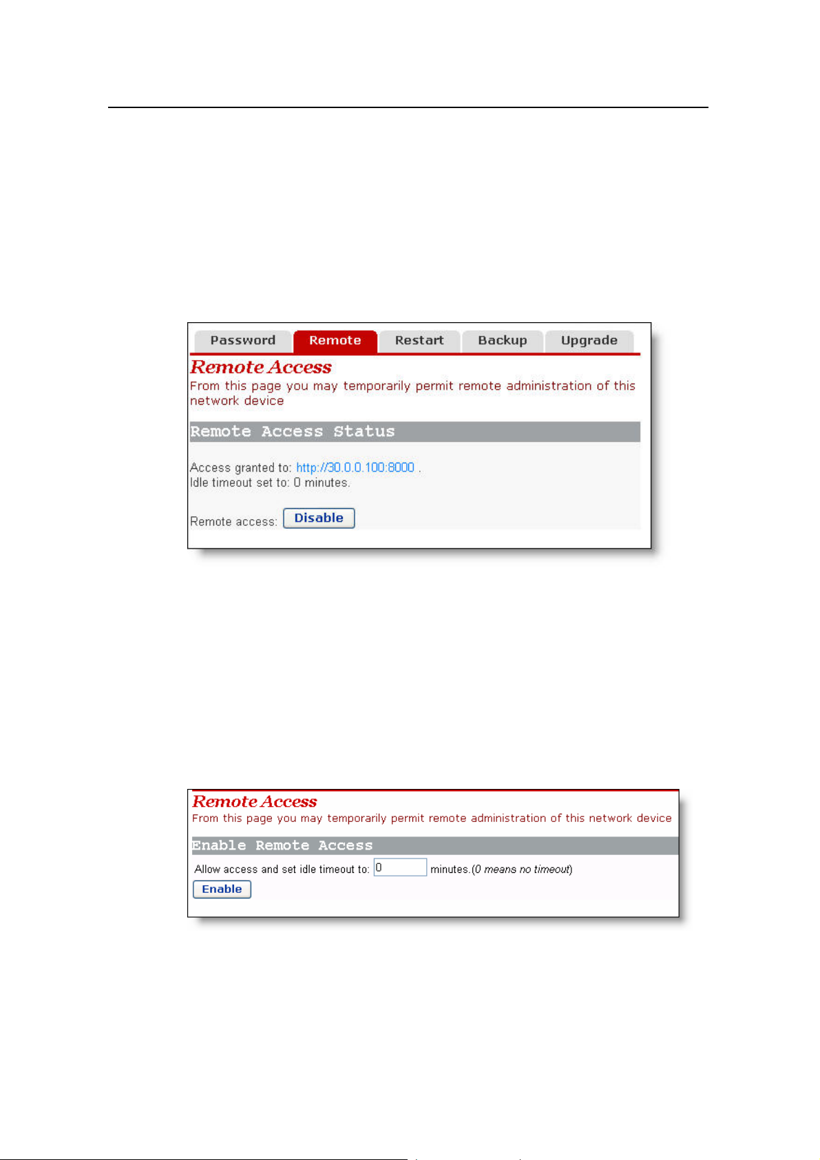
By default, the remote access is enabled and the idle timeout time is set to 0 (see
Figure 4-27). In this case, remote access is kept alive.
Figure 4-27 Remote access page – remote access enabled
Figure 4-27 indicates the port for remote management is 8000, so you can manage the
DR814Q remotely by entering http://xxx.xxx.xxx.xxx:8000 in your Web browse r. The
xxx.xxx.xxx.xxx is the IP address of the WAN port on the DR814Q. If multiple WAN
services are configured and all of them obtain the IP addresses, the IP address of any
service can be used for remote access.
To disable the remote access, click <Disable> on the [Remote Access] page to open
the page as below.
Figure 4-28 Remote access page – remote access disabled
In this case, you can set the idle timeout time to a desired value other than 0 in the text
box on the page. Thus, when you click <Enable> to enable the remo te access next time,
32
Page 38

User Manual
Aolynk DR814Q ADSL2+ Broadband Router 4 Web-based Basic Configuration
the DR814Q tracks the elapsed idle time and terminates the remote connection to
avoid remote attacks when the elapsed idle time exceeds the set idle time.
Caution:
A remote connectio n is maintained only when the idle timeout time is set to 0. If you set
the timeout time to another value, remote access is disabled automatically whenever
the DR814Q restarts.
Because remote access is enabled by default, you need to configure the password to
prevent network invasion by the Internet users.
4.4.3 Restarting/Restoring Factory Default Settings
This page allows you to restart the DR814Q, or reset all configurations to factory default
settings.
Figure 4-29 Restart Router page
To restart the DR814 Q, click <Restart>.
To reset all configurations to the factory default settings, select the [Reset to factory
default settings] check box and click <Restart>.
Caution:
It may take several seconds to restart the DR814Q.
33
Page 39

User Manual
Aolynk DR814Q ADSL2+ Broadband Router 4 Web-based Basic Configuration
4.4.4 Backing Up/Restoring Configuration
This page allows you to back up the current configuration to your PC, or restore the
configuration from a previously saved file.
Figure 4-30 Backup/Restore Configuration page
I. Back up the current configuration
Click <Backup> to open the [File Download] dialog box as below.
Figure 4-31 File Download dialog box
Click <Save> to open the [Save As] win dow as below.
34
Page 40
User Manual
Aolynk DR814Q ADSL2+ Broadband Router 4 Web-based Basic Configuration
Figure 4-32 Save the configuration file
Select a directory to save the file and type in a valid file name (with the .icf suffix), and
then click <Save> to back up the current configuration to the file.
II. Use the file to restore the configuration
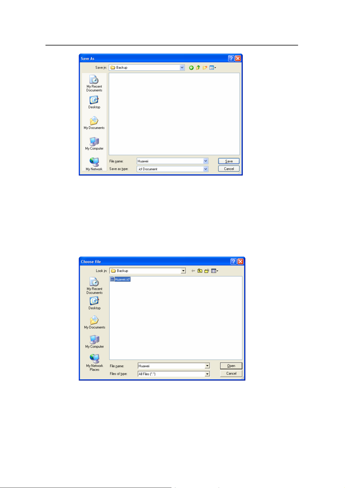
To use the previously saved file to restore the configuration, click <Bro wse…> in Figure
4-30 to open the [Choose file] window as below.
Figure 4-33 Choose the backup file
Find the configuration file and then click <Open> to open the page as below. Click
<Restore> to use the file to restore the configuration.
35
Page 41

User Manual
Aolynk DR814Q ADSL2+ Broadband Router 4 Web-based Basic Configuration
Figure 4-34 Restore the configuration
4.4.5 Upgrade
Figure 4-35 Software upgrade
This page allows you to upgrade the software of the DR814Q.Type in the local path of
the software update file downloaded from Huawei technical support website, or click
<Browse…> to select this file on your PC and then click <Update>.
During the update, a progress bar appears on the page as below.
36
Page 42
User Manual
Aolynk DR814Q ADSL2+ Broadband Router 4 Web-based Basic Configuration
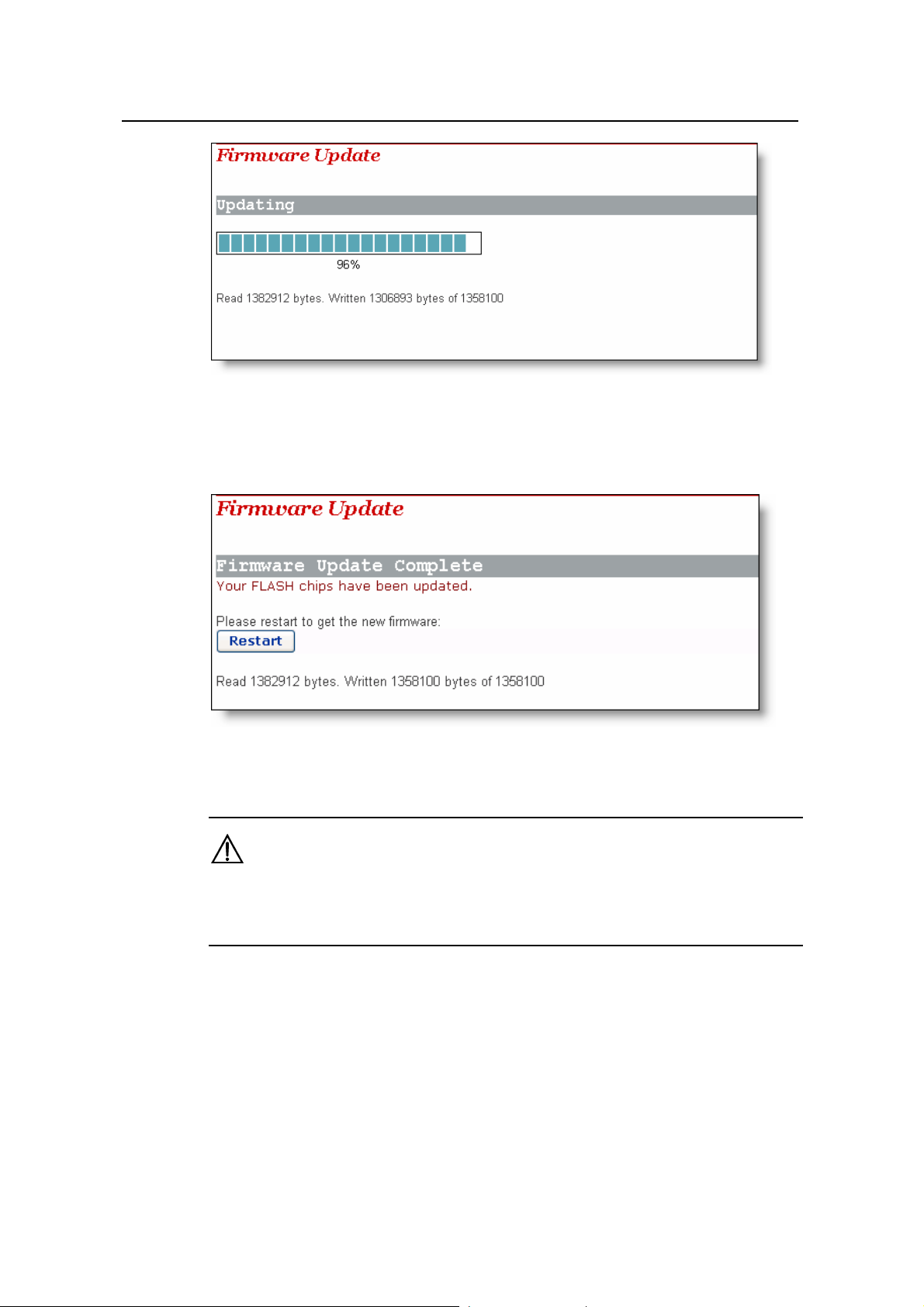
Figure 4-36 Update progress
Figure 4-37 shows that the update is complete. Now, you need to restart the DR814Q
by clicking <Restart>.
Figure 4-37 Complete the update
After the upgrade and restart, you need to restore fa ctory default settings to ensure the
normal configuration.
Click <Huawei> to access Huawei technical support website to obtain the latest
software version.
4.5 Status
Click [Status] in the navigation bar to enter the corresponding page where three tabs
are available: Status, Log, and Search Service. Click any tab to enter your desired
configuration page.
Caution:
37
Page 43

User Manual
Aolynk DR814Q ADSL2+ Broadband Router 4 Web-based Basic Configuration
4.5.1 Status
Figure 4-38 Status configuration page
This page displays useful information about the configuration of the DR814Q,
including:
z Details of network connection
z Some important system information (hardware and version information)
z Routing table
z Connection status of current DSL, Ethernet and USB port
z WAN port status
z LAN port status
z Statistics on all interfaces
38
Page 44

User Manual
Aolynk DR814Q ADSL2+ Broadband Router 4 Web-based Basic Configuration
4.5.2 Log
This page records all types of events occurring during the running of the DR811/814.
Figure 4-39 Log
The drop-down list in the [Select events to view] section includes the options as shown
in the figure below. Select an event type to view the corresponding event informa t ion.
Click <Clear these entries> to clear the currently displayed events.
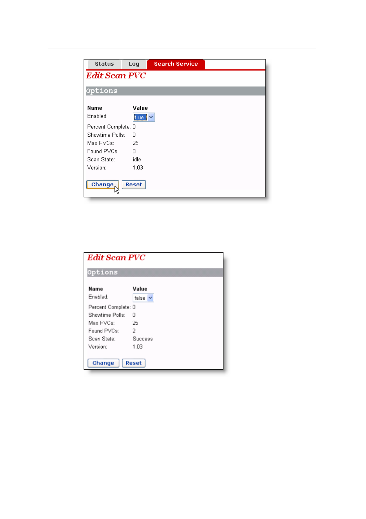
4.5.3 PVC Search
The [Edit Scan PVC] page allows you to search the currently unused PVC settings. If
your ISP has configured PVC services within the searchable range, after the search,
these PVC services will be automatically configured to the service list on the [WAN
Connections] page until the number of services reaches eight in this list.
39
Page 45
User Manual
Aolynk DR814Q ADSL2+ Broadband Router 4 Web-based Basic Configuration
Figure 4-40 PVC Scan page
Select the true option from the drop-down list in Figure 4-40, and then click <Change>
to start the search. It may take about five minutes.
Figure 4-41 Search PVC
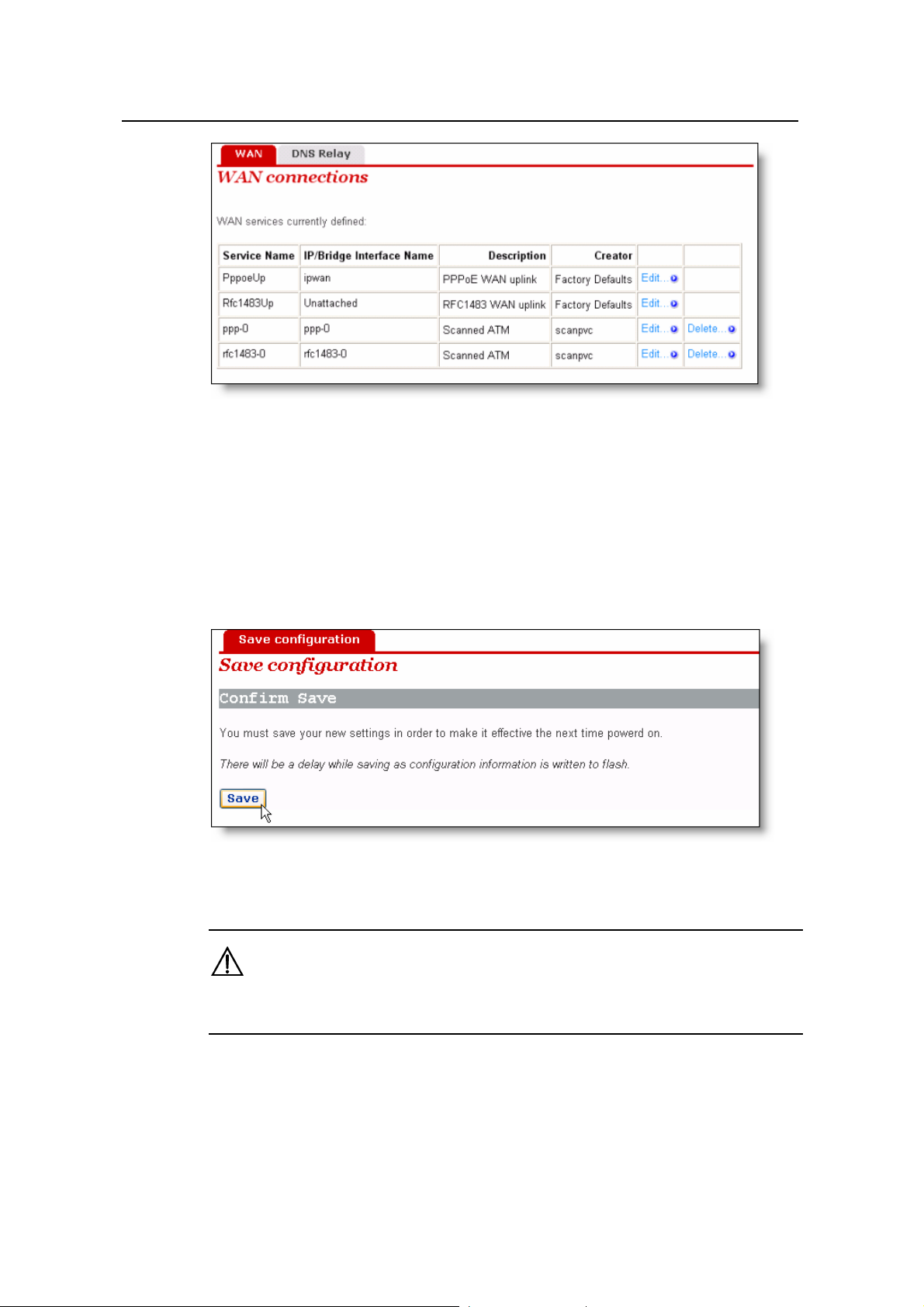
As shown in Figure 4-41, two PVCs are found. Click [WAN Setup] in the navigation bar ,
you will find that two services found by the DR814Q are automatically added to the
WAN service list as below.
40
Page 46
User Manual
Aolynk DR814Q ADSL2+ Broadband Router 4 Web-based Basic Configuration
Figure 4-42 Add the found services automatically
If the PPPoE or PPPoA service is found, you need to edit these automatically added
services by typing in a user name and a password.
4.6 Save the Configuration
Enter the [Save configuration] page after all the configurations are complete. Click
<Save> to save your configurations so that they take effect when the DR814Q rest arts.
Figure 4-43 Save the configuration
Caution:
Do save your settings, otherwise, they will be lost after the DR814Q restarts.
41
Page 47

User Manual
Aolynk DR814Q ADSL2+ Broadband Router 5 Advanced Configuration
5 Advanced Configuration
After you complete the proceeding configuration correctly, the DR814Q can access all
Internet services. This c
the DR814Q to enhance the performances, thereby satisfying various demands on
network configuration.
hapter introduces how to configure the advanced functions of
5.1 Bind
I.
ing LAN Ports to PVCs
Click [LAN/PVC] to enter the [Att
to a PVC and set the corre
PVC Binding Settings
With the PVC binding function, you can bind any of the four Ethernet ports (LAN ports)
to any of the four upstream PVCs. Each PVC bridges data from the bound Ethernet port
to the broadband access server (BAS) to accommodate different Internet services
through different Ethernet ports. Services such as the Internet
video-on-demand (VOD), and IPTV carried out by different access servers improve
security and stability of the system and ease the load of BASs remarkably.
Y ou can also configure an Ethernet port as a management port to manage devi ces. Y ou
can access the configuratio
connected to the management port. By default, the four LAN ports of the DR814Q are
all the management ports.
achment Setting] page. You can bind the Ethernet port
sponding QoS parameters for PVC.
accessing,
n management page of your DR814Q through a host that is
42
Page 48

User Manual
Aolynk DR814Q ADSL2+ Broadband Router 5 Advanced Configuration
Figure 5-1 PVC Binding Settings
As Figure 5-1 shows, there are five options for each Ethernet port (LAN1 to LAN4) in
the drop-down list: Attached to PVC1/2/3/4 and Attached to Router (Default).
Upon the configuration of these LAN ports, you need to click <Apply> to save your
configuration and have it take effect. Then in the [PVC Setting] section set VPIs/VCIs
for the corresponding PVCs. V alues of VPI/VCI are provided by your ISP. Click <Apply>
in this section to save your configuration.
Caution:
z You can manage your DR814Q only through the PC connected to the management
port or the USB port.
z If all the four Ethernet ports are configured to be bound to PVCs, you can still access
the configuration management page through the USB port. Refer to section 8
“Appendix - USB Configuration” for more information about the USB port.
z The VPI/VCI values of different PVCs cannot be identical with each other or the
same as those on the other configuration pages.
The following example illustrates the configuration upon the assumption:
z Bind a LAN port to PVC 0/35 to access the IPTV Website that your ISP set up. The
Website uses DHCP to assign IP addresses dynamically.
43
Page 49

User Manual
Aolynk DR814Q ADSL2+ Broadband Router 5 Advanced Configuration
z Bind other two LAN ports to PVC 0/100, and the PCs connecting to these ports
access the Internet through PPPoE dial-up connections.
z Route the last LAN port to access the Internet and apply NAT-enabled PPPoE
service on this port. Bind it to PVC 8/35. The user name and password your ISP
assigns are username and myPassword respectively.
Follow these steps to achieve the settings on your DR814Q.
1) On the [Ethernet Port Attachment Setting] page (see Figure 5-2), select the
Attached to PVC1 option from the LAN1 drop-down list to bind LAN1 to PVC1
and bind LAN2 and LAN3 to PVC2 in the same way. Leave the LAN4 default
setting Attached to Router untouched. Click the <Apply> to save your
configuration.
2) In the [PVC Setting] section, set 0/35 as the VPI/VCI value of PVC1, 0/100 as that
of PVC2.Click <Apply> in the [PVC Setting] section to save your settings. Since
you do not use PVC3 and PVC4 here, there is no need to specify VPI/VCI values
for them.
Figure 5-2 Actual configuration on the Attachment Setting page
3) Click <Quick Setup> in the navigation bar and select the PPPoE Login option on
the [WAN Connections] page. Set the values of VPI and VCI to 8 and 35
respectively, type userName, myPassword, and myPassword in the PPPoE
Username, PPPoE Password, and PPPoE Password (confirm) text boxes
respectively and then click <Apply> to save your settings.
44
Page 50

User Manual
Aolynk DR814Q ADSL2+ Broadband Router 5 Advanced Configuration
Figure 5-3 Set the PPPoE authentication information
4) It takes about two minutes for your settings to take effect. Figure 5-4 depicts these
settings. Actual configuration on the WAN connection s page Cli ck <Status> in t he
navigation bar to bring up the [Status] page as shown in Figure 4-38. You can find
that the WAN IP Address item is a public IP address instead of the original one
0.0.0.0. Then you can access the Internet through a PC connected to the LAN4
port.
Figure 5-4 Actual settings on the Status page
5) Verify the binding of the LAN ports to the PVCs. Connect a PC which is configured
to obtain an IP address automatically to the LAN1 port. You can then access the
IPTV Website of your ISP. Similarly, connect PCs to the LAN2 and LAN3 ports and
access the Internet by PPPoE connection. After you enter the user name and
password, the PC can obtain an IP address quickly and set up a connection with
the Website.
45
Page 51

User Manual
Aolynk DR814Q ADSL2+ Broadband Router 5 Advanced Configuration
II. QoS configuration
For the upstream packets over an ADSL line, your DR814Q supports multiple
asynchronous transfer mode (ATM) services, such as CBR, VBR-rt, VBR, UBR, and
ABR. DR814Q provides different measures, caching space, scheduling priorities, and
service shaping to allocate appropriate bandwidth to ATM services of different types.
This ensures high-performance QoS.
Click <QoS Setting…> in the [PVC Setting] section as shown in Figure 5-1 to enter the
[QoS Config] page of a corresponding PVC as below.
Figure 5-5 QoS Config page
You can set different ATM service types for specified PVCs from the ATM Traffic Class
drop-down list and configure QoS parameters for the selected service type. For more
information, refer to Table 5-1.
Table 5-1 Description of commonly used ATM service types
Service type Description
Suitable for services that are not real-time-critical and with large
burst traffic. UBR demands best-effect services on the network
UBR
(unspecified
bit rate)
side. When applying for services, you are not required to set QoS
parameters except for PCR, which limits the upper rate. The
network side does not guarantee QoS for UBR services. UBR cells
will be discarded first in a network congestion. Error correction is
carried out by upper-layer protocols. Typical applications are FTP
and E-mail.
Suitable for services that require static bandwidth and demand the
CBR
(constant bit
rate)
highest priority. This type of service can provide stable traffic with
the minimum burst. Only PCR parameter is needed for CBR service
application. The source can transmit cells at a negotiated PCR or a
rate lower than it. Typical applications are circuit and emulated
voice.
46
Page 52

User Manual
Aolynk DR814Q ADSL2+ Broadband Router 5 Advanced Configuration
Service type Description
Sensitive to delay and jitter of data flow . Similar to CB R except that
VBR-rt
(real-time
variable bit
rate)
they are delay- and jitter-sensitive. VBR-rt services allow limited
burst. The transmission rate on source side can be different at
different time. The parameters required for VBR-rt service
application include PCR, SCR, and MBS or BT. Typical VBR-rt
applications are voice and interactive video services and IPTV.
Suitable for bursting non-real-time services. Compared to VBR-rt, a
VBR
(non-real-time
variable bit
rate)
distinct feature of VBR services is that demands of real-time are not
so crucial, and the priority for service data processed on the
network side is also lower than that of VBR-tithe parameters
required by VBR services include PCR, SCR, and MBS (or BT), the
same as that of VBR-rt.
Keep 0 unchanged for those options unrelated to the configuration. As shown in Figure
5-5, if VBR-rt is selected from the ATM Traffic Class drop-down list, you need to set
values for Peak Cell Rate, Max Burst Size, and Sustainable Cell Rate and leave 0 in the
Burst Tolerance and Minimum Cell Rate text boxes.
An example is taken to explain how to configure ATM QoS parameters. You must
configure to meet the following requirements for the ATM QoS parameters of your
DR814Q to take effect:
z The digital subscriber line access multiplexer (DSLAM) has a relax control or even
no control over the LAN port and PVC upstream rates, entirely depending on the
ADSL line. The actual upstream rate of ADSL can be 896 Kbps at most if DSLAM
supports ADSL only .
z Multiple PVCs are configured on a single ADSL line.
Suppose that:
The downstream rate of each PVC is strictly specified by the central office (CO),
whereas the upstream rates of the PVCs are all configured to 896 Kbps.PVC1 and
PVC2 are configured on each ADSL line, among which you use PVC1 to access the
Internet and PVC2 to provide video chatting service.
Analysis:
Although an upstream rate of 896 Kbps is configured to PVC1 and PVC2 respectively
at the CO, audio and video services carried out over them may still be interfered. For
example, an uploading service, which consumes a bandwidth lager than 500 Kbps,
bursts on PVC1 when a video conference, which requires a minim um bandwidth of 384
Kbps for both upstream and downstream rates, is carried out over PVC2. This result s in
the available bandwidth for PVC2 less than 384 Kbps, thus causing the audio a nd video
service interrupted.
To avoid this, configure the QoS param eters as follo ws:
1) Click <QoS Setting…> in the [PVC Setting] section as shown in Figure 5-1 to enter
the [QoS Config] page of PVC2.
47
Page 53

User Manual
Aolynk DR814Q ADSL2+ Broadband Router 5 Advanced Configuration
2) Select the VBR-rt option from the ATM Traffic Class drop-down list.
3) Set Peak Cell Rate to 2000 (approximately 800 Kbps), Max Burst Size to 6000,
and Sustainable Cell Rate to 1000 (approximately 400 Kbps).
4) Click <Apply> to save your settings.
Figure 5-6 QoS configuration
For PVC1, keep the default UBR settings unchanged. Thus, PVC1 can occupy all the
upstream bandwidth when there is no traffic on PVC2, and PVC2 can always be
guaranteed with an average bandwidth of 400 Kbps for audio and video service s over it.
This ensures normal upload over PVC1 and non-interrupted real-time communication
over PVC2.
5.2 Security
Click [Security] in the navigation bar to enter the corresponding page where four tabs
are available: Interface, Policy, Trigger and IDS. Click any tab to enter your desired
configuration page.
5.2.1 Interface
Every firewall policy is intended for access between security interfaces. This page
allows you to enable the security function and configure security interfaces.
48
Page 54

User Manual
Aolynk DR814Q ADSL2+ Broadband Router 5 Advanced Configuration
Figure 5-7 Add a security interface
I. Security state
To enable/disable the security function, select the corresponding Enabled/Disabled
option, and then click <Change State>.
Likewise, such operation can also be used to enable/disable the firewall and intrusion
detection.
Caution:
z You can enable the firewall, intrusion detection and NAT only when the security
function is enabled.
z If the security function is disabled, the firewall, intrusion detection and NAT are also
necessarily disabled.
II. Security level
After the firewall is enabled, the [Security Level] drop-down list appears in the [Security
Level] section as below .
49
Page 55

User Manual
Aolynk DR814Q ADSL2+ Broadband Router 5 Advanced Configuration
Figure 5-8 Security Level drop-down list
This drop-down list includes the following options:
z none: (default setting) Indicates that the external and internal users have no
access right.
z high: Indicates that the internal users have some access rights and the external
users have no access right.
z medium: Indicates that the external and internal users have more access rights.
z low: Indicates that the external and internal users have the maximum access
rights.
z default: Indicates that the internal users can access all the Internet services, the
external users are prevented to access the internal network
To set the corresponding security level, select an option from the drop-down list, and
then click <Change Level>.
50
Page 56
User Manual
Aolynk DR814Q ADSL2+ Broadband Router 5 Advanced Configuration
Caution:
z By default, the none security level is not configured with port filtering policies. In this
case, internal users cannot access all the Internet services, and the internal network
cannot be accessed from the outside, either. To enable the access right to a service ,
you need to configure the corresponding port policy.For details, refer to section
5.2.2 “Policy”.
z The default port filtering policies are configured to the security levels except none.
After a security level is set, the corresponding policy appears on the port filtering
page.You can also configure a policy manually as needed.For details, refer to
section 5.2.2 “Policy”.
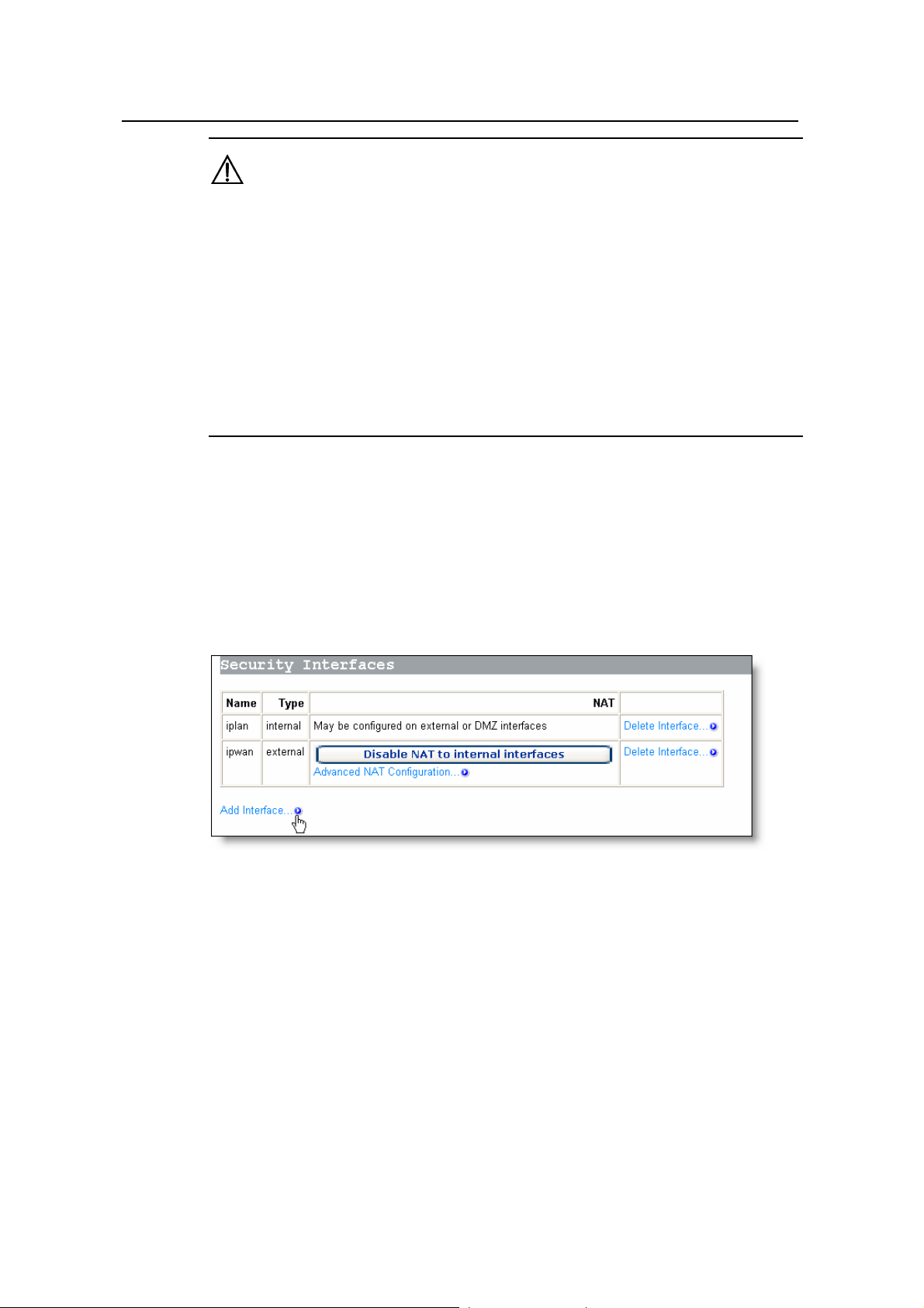
III. Security interface
You can establish the corresponding firewall policy between a group of security
interfaces. The security interface table lists the information about existing security
interfaces. By default, the DR814Q defines all interfaces as security ones and you
cannot create a new security interface any more. If you have created a virtual interface
(refer to section 4.3.1 “LAN”), <Add Interface…> appear on the page as below.
Figure 5-9 Security interface
In this case, you can add a security interface by clicking <Add Interface…> to enter th e
page as below.
51
Page 57

User Manual
Aolynk DR814Q ADSL2+ Broadband Router 5 Advanced Configuration
Figure 5-10 Security – add an interface
Select an interface type, external, internal or DMZ from the [Interface Type]
drop-down list, and then click <Apply>.The configured interface has been added to the
security interface table on the [Security Interfaces] section as below.
Figure 5-11 Security interface table
To delete a security interface, click the co rresponding <Delete Interface…> button, and
then click <Delete> on the [Delete Interface] page.
52
Page 58

User Manual
Aolynk DR814Q ADSL2+ Broadband Router 5 Advanced Configuration
Figure 5-12 Delete a security interface
IV. NAT configuration
The NAT technology can translate an internal private address into a valid public IP
address, and thus PCs in the LAN can share a public IP addre ss for network access.
You can click the three buttons on the page as shown in Figure 5-11 to enable/disable
NAT between the three types of interfaces. After the NAT is enabled, you can perform
advanced NAT configuration. Click <Advanced NAT Configuration…> to enter the
configuration page as below.
Figure 5-13 Advanced NAT configuration
1) Global address pool
This page allows you to add a public IP address obtained from your ISP to the global
address pool. After NAT is enabled, internal addresses are randomly translated to an
unused address in this pool.
53
Page 59

User Manual
Aolynk DR814Q ADSL2+ Broadband Router 5 Advanced Configuration
To add a public IP address or an address pool, click <Add Global Address Pool…> to
enter the configuration page as below.
Figure 5-14 Add a global IP address pool
Table 5-2 Description on the items of the global IP address pool
Item Description
Interface Type
Select the interface type corresponding to a public IP address from
the drop-down list.
Select the method to specify the address from the drop-down list.
Use Subnet
Configuration
The Use Subnet Mask option indicates to specify a network
segment. The Use IP Address Range option indicates to specify a
range of the IP address.
Type in the IP address of a segment if the Use Subnet Mask
IP Address
Subnet
Mask/IP
Address2
option is selected. Type in the start IP address if the Use IP
Address Range option is selected.
Type in the subnet mask of the segment if the Use Subnet Mask
option is selected. Type in the end IP address if the Use IP
Address Range option is selected.
Click <Add Global Address Pool> after the configuration is complete. This IP address
will be added to the address pool.
2) Virtual server
After NAT is enabled, the internal network devices cannot be accessed from the
Internet. To provide public services such as Web se rver , Email and FTP for the outside,
a virtual server needs to be configured to make the network computer with private static
IP address provide these services. Although the internal service address cannot be
accessed by external users directly, the DR814Q can identify service requests through
port number and forward them to the virtual server.
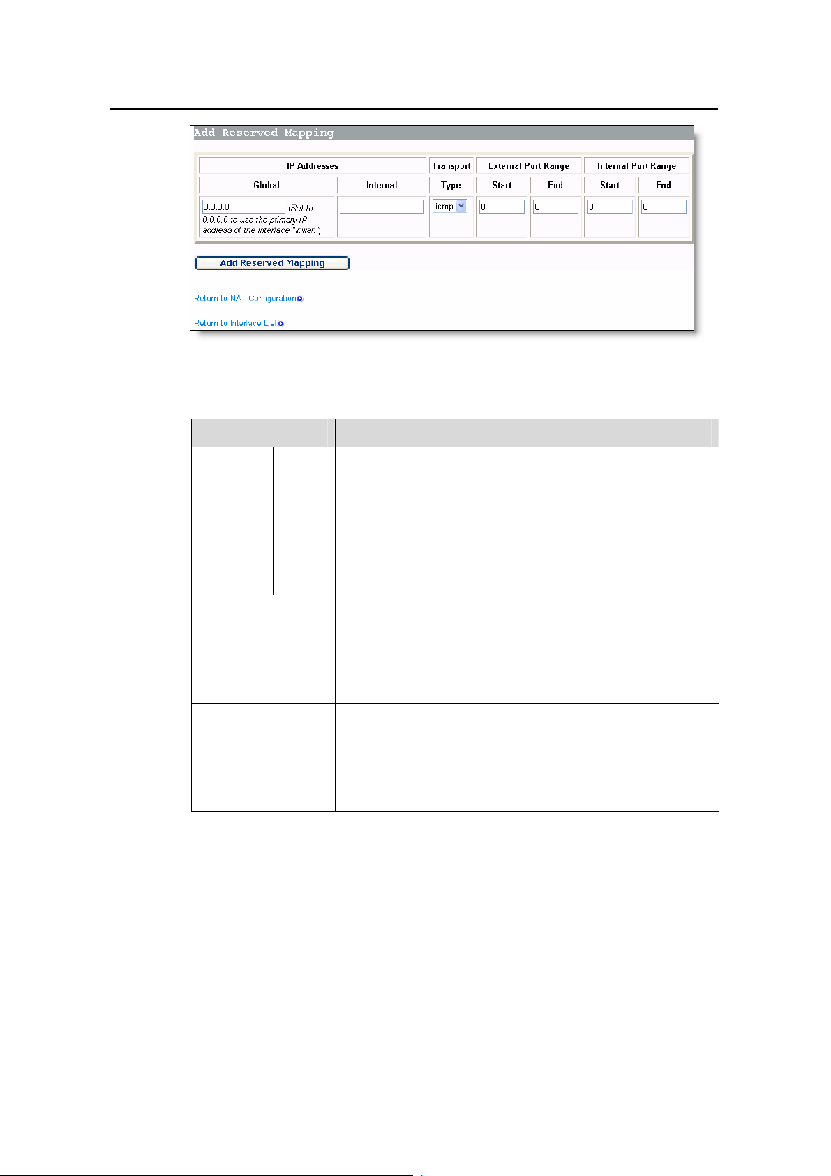
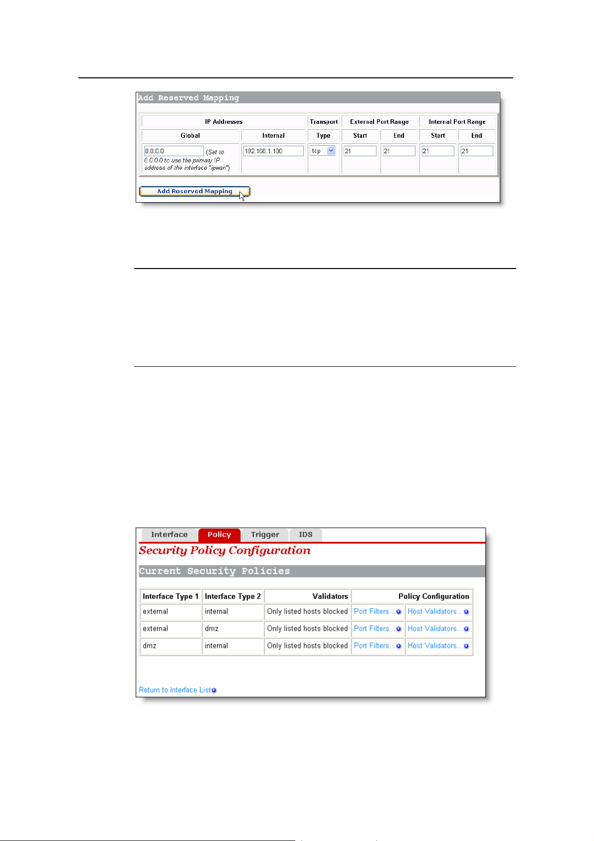
To configure a virtual server, click <Add Reserved Mapping…> in the [Reserved
Mappings] section (see Figure 5-13) to enter the page as below.
54
Page 60
User Manual
Aolynk DR814Q ADSL2+ Broadband Router 5 Advanced Configuration
Figure 5-15 Virtual server configuration page
Table 5-3 Description on the items of the virtual server
Item Description
The default address, 0.0.0.0, can be reserved which means
IP
Global
that the address obtained from the W AN port is used. Or you
can type in the address from the global address pool.
Address
Internal
Type in the IP address of internal PC providing application
services.
Transport Type
Select the protocol type for the application service from the
drop-down list.
Most application services forward inbound and outbound
packets through the same port. In this case, you can just
External Port Range
configure Start and End as this port number. But some
application services forward inbound and outbound packets
respectively through different ports. In thi s case, you need to
type in the port range used by the inbound packets.
Most application services forward inbound and outbound
packets through the same port. In this case, you can just
Internal Port Range
configure Start and End as this port number. But some
application services forward inbound and outbound packets
respectively through different ports. In thi s case, you need to
type in the port range used by the outbound packets.
Click <Add Reserved Mapping> after the configuration is complete .
Example: To configure the PC with the address 192.168.1.100 as a virtual server to
provide an FTP service for the outside (with the port number 21), refer to the
configuration in Figure 5-16. Thus, all FTP requests from the Internet users will be
forwarded to the PC (server) with the fixed IP address 192.168.1.100.
55
Page 61
User Manual
Aolynk DR814Q ADSL2+ Broadband Router 5 Advanced Configuration
Figure 5-16 Example of the virtual server configuration
Note:
NAT can work between:
z External interface and internal interface
z External interface and DMZ
z DMZ and internal interface.
5.2.2 Policy
Security policy is a rule set to limit inbound and outbound data between differen t types
of interfaces. The DR814Q provides a powerful security module to support the firewall
policies configured between external and internal interfaces, between external
interface and DMZ, and between DMZ and internal interface respectively, thereby
satisfying various demands on network security. The firewall must be enabled before
the creation of a policy.
Figure 5-17 Security policy configuration
56
Page 62

User Manual
Aolynk DR814Q ADSL2+ Broadband Router 5 Advanced Configuration
I. Port filter
You can configure the port filtering policy to limit the data transmission of a protocol
type.
To configure a group of interfaces (suppose external interface and internal interface)
with the port filtering policy, click the corresponding <P ort Filters… > button to enter the
page as below.
Figure 5-18 Firewall port filter
This page lists the currently configured policies. Select dif ferent firewall security level to
display the corresponding port filtering policies. Other types of packet requests not
configured with the policies will be blocked by the firewall.
To delete a policy, click the corresponding <Delete> button, and then click <Delete> to
confirm on the popup page.
To add a policy for the port number of the protocol, click <Add TCP or UDP Filter> to
enter the page as below.
57
Page 63

User Manual
Aolynk DR814Q ADSL2+ Broadband Router 5 Advanced Configuration
Figure 5-19 TCP/UDP port filtering policy
Table 5-4 Description on the items of TCP/UDP port filter
Item Description
Source
address
Destination
address
Protocol
Source
port
Destination
port
Direction
IP
Address
Mask
IP
Address
Mask
Range
Start-End
Range
Start-End
Inbound
Outbound
Type in the source IP address. The default address
0.0.0.0 indicates any node on the network.
Type in the subnet mask of the source. The default mask
0.0.0.0 indicates any node on the network.
Type in the destination IP address. The default address
0.0.0.0 indicates any node on the network and is usually
reserved.
Type in the subnet mask of the destination. The default
mask 0.0.0.0 indicates any node on the network and is
usually reserved.
Select a protocol type (TCP or UDP) from the drop-down
list and apply the filtering policy to the packets of this
type.
Type in the port range of the source. The default range
from 0 to 65535 indicates any node and is usually
reserved.
Type in the port range of the destination. Generally, this
parameter needs to be set. For example, to control Web
services, type in the corresponding port number 80. To
control FTP services, type in the port number 21.
The direction of inbound data. Select Allow to permit
external hosts to access internal hosts. Select Block to
forbid external hosts to access internal hosts.
The direction of outbound data. Select Allow to permit
internal hosts to access external hosts. Select Block to
forbid internal hosts to access external hosts.
Click <Apply> after the configuration is complete. This policy will be added to the list of
port filtering policies.
58
Page 64

User Manual
Aolynk DR814Q ADSL2+ Broadband Router 5 Advanced Configuration
Example: If you want the internal users to access the external HTTP server (with the
port number 80), but do not want the external users to access the int ernal HTTP serv er ,
you can perform the configuration as below.
Figure 5-20 Example of the port filtering configuration
To add a policy for a protocol, click <Add Raw IP Filter> in Figure 5-18 to enter the p age
as below.
Figure 5-21 Filtering policy based on the protocol type
Table 5-5 Description on the items of the filtering policy
Item Description
Source
address
Destination
address
IP
Address
Mask
IP
Address
Mask
Type in the source IP address. The default address
0.0.0.0 indicates any node on the network.
Type in the subnet ma sk of the source. The default mask
0.0.0.0 indicates any node on the network.
Type in the destination IP address. The default address
0.0.0.0 indicates any node on the network and is usually
reserved.
Type in the subnet mask of the destination. The default
mask 0.0.0.0 indicates any node on the network and is
usually reserved.
59
Page 65

User Manual
Aolynk DR814Q ADSL2+ Broadband Router 5 Advanced Configuration
Item Description
Type in a protocol name or number and apply this
filtering policy to the packets of this type. The protocol
name can be TCP, UDP or ICMP. For other protocols,
you need to type in their protocol numbers. For example,
type in 2 for IGMP, and 46 for RSVP.
IP Protocol
Number or
name
The direction of inbound data. Select Allow to permit
Inbound
external hosts to access internal hosts. Select Block to
forbid external hosts to access internal hosts.
Direction
The direction of outbound data. Select Allow to permit
Outbound
internal hosts to access external hosts. Select Block to
forbid internal hosts to access external hosts.
Click <Apply> after the configuration is complete. This policy will be added to the list of
port filtering policies.
Example: By default, the external hosts are not allowed to ping the WAN port even if the
security level is set to low. To allow the internal hosts and external hosts to ping each
other, you can perform the configuration as below.
Figure 5-22 Example of the filtering policy for a protocol (2)
II. Host validators
By specifying the IP address and configuring the corresponding policy, you can restrict
the access right of a host or hosts on a network seg m ent.
To configure host validators to a group of interfaces, click the corresponding <Host
V alidators…> button in the [Current Security Policies] section (see Figure 5-17) to enter
the page as below.
60
Page 66

User Manual
Aolynk DR814Q ADSL2+ Broadband Router 5 Advanced Configuration
Figure 5-23 Host validators page
To add a host validator policy, click <Add Host Validator…> to enter the page as below.
Figure 5-24 Configure a host validator
Table 5-6 Description on the items of the host validator
Item Description
Host IP Address
Host Subnet
Mask
Type in the IP address of the host or network segment to be
restricted.
Type in the subnet mask of the host or network segment to be
restricted.
Select the direction of data transmission. Select inbound to
Direction
block the inbound data only. Select outbound to block the
outbound data only. Select both to block both inbound data and
outbound data.
Example: To block a host with the IP address 192.168.1.10 in the LAN to access an
external network, and permit the external users to access this host, you can perform
the configuration as below, and then click <Apply>.
61
Page 67

User Manual
Aolynk DR814Q ADSL2+ Broadband Router 5 Advanced Configuration
Figure 5-25 Example of the host validator configuration (1)
Example: If you find a suspicious host (with the IP address 10.1.1.2) in an external
network, you can set the host validator policy as below to block its att ack on the internal
host.
Figure 5-26 Example of the host validator configuration (2)
As shown in Figure 5-26, inbound is selected from the [Direction] drop-down list, and
thus the device only block the data from the address 10.1.1.2 to the internal host while
the internal host can still send data to the address 10.1.1.2.
Caution:
z The host validator can be used to limit the data stream between the WAN and LAN
ports.
z The security policy takes effect only when the firewall is enabled.
62
Page 68

User Manual
Aolynk DR814Q ADSL2+ Broadband Router 5 Advanced Configuration
5.2.3 Trigger
A security trigger is used to deal with application protocols that set up separate
sessions. Some application protocols, such as NetMeeting, open t he p rimary se ssion s
and secondary connections at the same time during the normal operations. The trigger
tells the security mechanism to handle these secondary sessions and instruct it how to
handle them. The trigger handles the situation dynamically, allowing the secondary
sessions only when appropriate. These newly triggered sessions are not restricted by
the firewall.
Figure 5-27 Security trigger
This page allows you to:
z View the information in the current security trigger list.
z Create a new security trigger and add it to the current security trigger list.
z Delete an existing security trigger.
To create a new security trigger, click <New Trigger> to enter the page as below.
Figure 5-28 Add a security trigger
63
Page 69

User Manual
Aolynk DR814Q ADSL2+ Broadband Router 5 Advanced Configuration
Table 5-7 Description on the items of the security trigger
Item Description
Transport Type
Port Number St art
Port Number End
Secondary Port
Number Start
Secondary Port
Number End
Allow Multiple
Hosts
Max Activity
Interval
Enable Session
Chaining
Enable UDP
Session Chaining
From the drop-down list, select a transport type (TCP or UDP)
to which the newly added trigger is specified.
Type in the start of the trigger port range that the primary
session uses.
Type in the end of the trigger port range that the primary
session uses.
Type in the start of the trigger port range that the secondary
session uses.
Type in the end of the trigger port range that the secondary
session uses.
Select Allow if you want a secondary session to be initiated by
different remote hosts. Select Block if you want a secondary
session to be initiated only by one remote host.
Type in the maximum activity interval (in milliseconds) for
secondary port sessions after the primary session starts.
Select Allow or Block to determine whether the multi-level
TCP session chaining is accepted or not.
Select Allow or Block to determine whether the multi-level
UDP session chaining is ac cepted or not. Before this, you mu st
enable the session chaining.
Binary Address
Replacement
Address
Translation Type
Select Allow or Block to determine whether to use the binary
address replacement on the current trigger or not.
Specify the address replacement type on a trigger. Before this,
you must set the binary address replacement to Allow.
Click <Apply> after the configuration is complete. The [Security Trigger Configuration]
page is displayed, containing det ails of the trigger that you have just configured.
To delete an existing security trigger, click the corresponding <Delete> button in Figure
5-27 and then click <Delete>.
64
Page 70

User Manual
Aolynk DR814Q ADSL2+ Broadband Router 5 Advanced Configuration
Figure 5-29 Delete a security trigger
In fact, the DR814Q has provided an Application Level Gateway (ALG) for NetM eeting.
NetMeeting applications can be also normal even if the port trigger is not configured.
The following example is taken to show how to configure a port trigger if the DR814Q
does not provide the ALG for NetMeeting.
Suppose your PC is connected to the LAN interface of the DR814Q, and you want to
use NetMeeting to have an audio/video chat with Internet users, and to apply
whiteboard and program sharing.
Analysis:
A NetMeeting call is established on the TCP 1720 port. After the connection is
established, NetMeeting needs to re-enable the TCP 1503 port to use whiteboard and
program sharing. NetMeeting also needs to enable any port of TCP and UDP protocols
within the range of 1024 to 65535 to transmit audio and video signals. Af ter the firewall
is enabled, you can configure the port filtering policies and virtual servers of TCP and
UDP protocols to all ports within the range. In this way, Internet users can actively call a
LAN user during the use of NetMeeting. However, possible omission in configuring the
filtering policy and virtual server may cause the failure of the audio/video chat
establishment. Moreover, the virtual server configuration exposes almost all the LAN
host ports to the Internet, resulting in the insecurity of the host.
To solve these problems, you can perfo rm the configuration as below to make the TCP
1720 port trigger TCP/UDP port within the range of 10 24 to 65535.
Figure 5-30 Example of the trigger configuration
65
Page 71
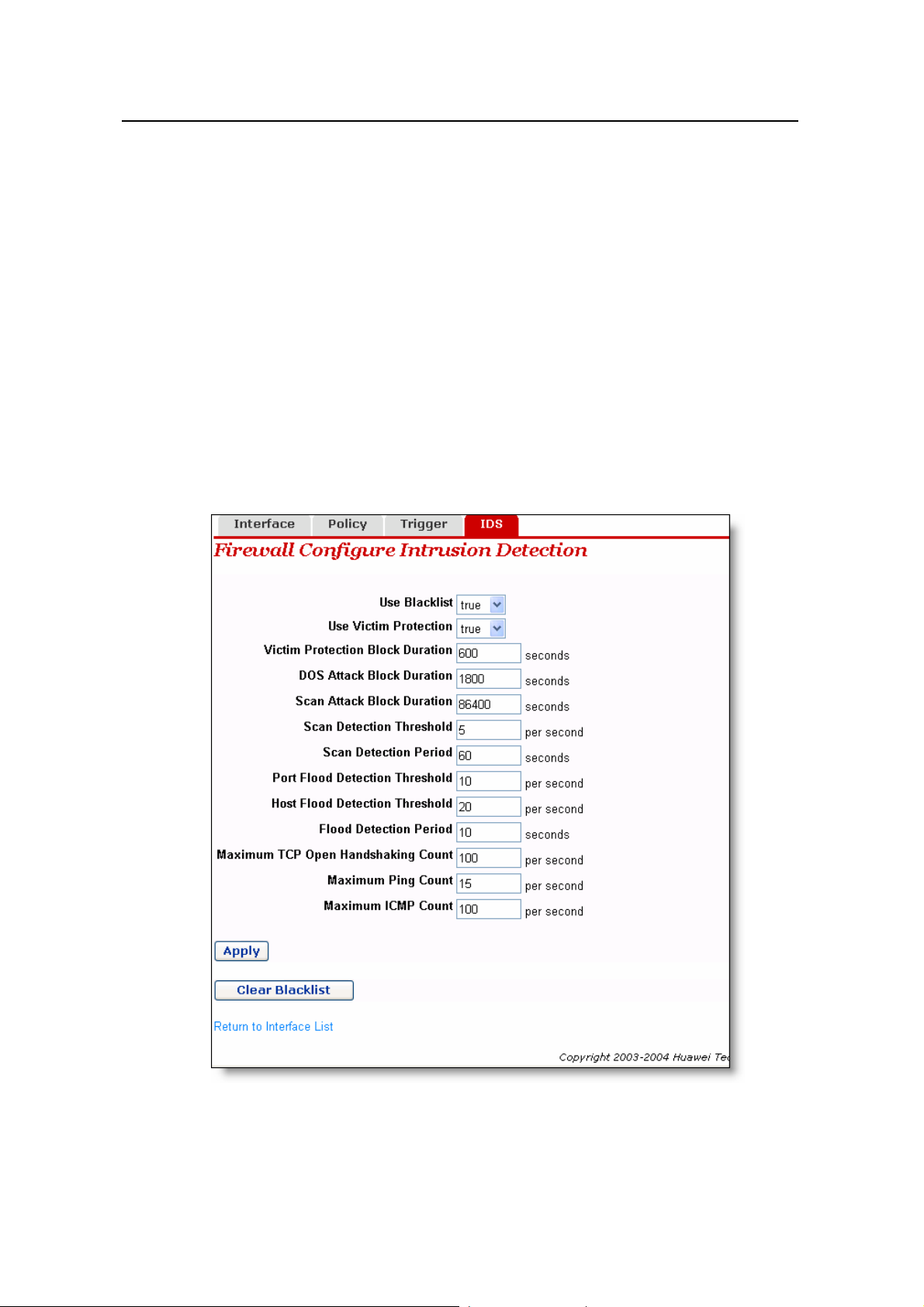
User Manual
Aolynk DR814Q ADSL2+ Broadband Router 5 Advanced Configuration
In this way, all applications provided by NetMeeting can be used normally after a LAN
user calls the Internet user and you can just add the access policy suitable for packet s
on the TCP 1720 port on the corresponding page (see Figure 5-19).To make the
Internet users call LAN users and use NetMeeting normally, you can just configure the
virtual server on the TCP 1720 port on the corresponding page (see Figure 5-15) and
combine it with the port trigger mentioned previously.
5.2.4 IDS
IDS protects the current network from the following attacks:
z Denial of Service (DoS).
z Port scanning.
z Web spoofing.
IDS also implements the blacklist function. It stops external hosts that try to invade the
network from accessing the DR814Q within a specific time limit.
Figure 5-31 IDS configuration
66
Page 72

User Manual
Aolynk DR814Q ADSL2+ Broadband Router 5 Advanced Configuration
Table 5-8 Description of the IDS configuration items
Item Description
Select true or false to enable or disable the blacklist function.
When the external host attacks (Ascend Kill, Echo Scan,
Use Blacklist
WinNuke, Xmas Tree Scan, IMAP SYN/FIN Scan, SMURF,
TCP SYN Flood, Net Bus Scan and Back Orifice Scan) are
found, these hosts are put into the blacklist and their packets
are filtered out within the set time limit.
Select true or false to enable or disable the Smurf protection
which protects the DR814Q against attacks caused by pings
with a broadcast address. The attacker may broadcast pings
Use Victim
Protection
with the victim’s MAC address as the source MAC address.
Without this protection, hosts in LAN will send response
packets to the victim when receiving these packets, and even
cause the collapse of the victim. With this protection, the
DR814Q will detect and drop ICMP packets sent by the attacker
and continue to do so within a specific time limit.
Block duration of Web Spoofing (Smurf) attacks on the host. If
Victim Protection
Block Duration
the device detects these attacks, it will filter all the ICMP
packets that attack the host and continue to do so within a
specific time limit. The default value is 10 minutes.
DOS Attack Block
Duration
Scan Attack Block
Duration
Scan Detection
Threshold
Scan Detection
Period
Block duration of DoS attacks on the host. If the DR814Q
detects these attacks, it will filter all the packets that attack the
host and continue to do so within a specific time limit. The
default value is 30 minutes.
DoS attacks will prevent legitimate users from accessing
normal Internet services. The DoS attacks that the device can
detect include Smurf Att ack, SY N/FIN/RST Flood, ICMP Flood,
Ping Flood, Ascend Kill, WinNuke Attack and Echo Chargen.
Block duration of port scanning attacks on the host. If the
DR814Q detects these attacks, it will filter all the packets that
attack the host and continue to do so within a specific time limit.
The default value is 24 hours.
Threshold of port scanning packet s. When the DR814Q detects
port scanning packets (such as SYN/ACK, FIN or RS T) sent by
a host per second and the number of packets reaches the
threshold, the device regards them as port scanning attacks.
The port scanning attacks that the device can detect include
Echo scan, Xmas Tree scan, IMAP scan, TCP SYN ACK scan,
TCP FIN RST scan, NetBus scan, Back Orifice scan and
SubSeven.Most of port scanning attacks are the Trojan Horse
attack.
Statistics duration of port scanning. When the device detects
that port scanning continues to reach the set time, the device
will block all the packets that att ack the host and co ntinue to d o
so within the time limit set in the [Scan Attack Block Duration]
text box.
The default value is 60 seconds.
67
Page 73

User Manual
Aolynk DR814Q ADSL2+ Broadband Router 5 Advanced Configuration
Item Description
When the device detects that TCP SYNC packets sent by a
host per second to a fixed port exceed this threshold, the devi ce
Port Flood
Detection
Threshold
will time the Flood attack. If the timing reaches the limit set in
the [Flood Detection Period] text box, the DR814Q concludes
that the host is making a port flood attack, and starts blocking
the packets sent by the host.
The default value is 10.
When the device detects that TCP SYNC packets sent by a
host per second exceed this threshold, the device will time the
Host Flood
Detection
Threshold
Flood attack. If the timing reaches the limit set in the [Flood
Detection Period] text box, the DR814Q concludes that the host
is making a port flood attack, and starts blocking the packets
sent by the host.
The default value is 20.
When the DR814Q detects that the duration of Flood attack by
Flood Detection
Period
a host reaches the set detection period, the device starts
blocking the packets sent by the host.
The default value is 10 seconds.
Maximum TCP
Open
Handshaking
Count
When the open handshaking count that the DR814Q receives
per second from a host exceeds the set value, the device
concludes that the SYN/ACK attack is detected.
The default value is 100.
The attacker may send a number of ping packets to a network.
These packets consume too much bandwid th and make normal
Maximum Ping
Count
network services unavailable. When the device detect s that the
count of ping packets sent by a host per second exceeds the
set value, the device concludes that the ping flood attack is
detected.
The default value is 15.
The attacker may send a number of ICMP (non -Echo Req uest)
packets to a network. These packets consume too much
Maximum ICMP
Count
bandwidth and make normal network services unavailable.
When the device detects that the count of ICMP packets sent
by a host per second exceeds the set value, the device
concludes that the ICMP Flood attack is detected.
The default value is 100.
To modify the current IDS configuration, type in the relevant values of IDS options, and
then click <Apply>.
To clear the blac klist, click <Clear Blacklist>.
68
Page 74

User Manual
Aolynk DR814Q ADSL2+ Broadband Router 5 Advanced Configuration
Caution:
By default, the security mode is enabled.
5.3 DMZ Configuration
The Demilitarized Zones (DMZ) feature of DR814Q allows you to configure a DMZ in a
LAN. The hosts that are configured on the same segment with this DMZ can perform
bi-directional communication with other Internet users or servers. At the same tim e, you
can enable NAT and configure a firewall policy between DMZ interface and internal
interface, and between DMZ interface and external interface. This not only provides a
security shelter for the hosts in the DMZ, but also satisfies the needs of server
installation in LANs by small and medium-size d enterprises to provide services su ch as
FTP and Web for bi-directional communication with users.
The following figure depicts the steps to configure DMZ:
WDR854gDR814QWDR854gDR814Q
Figure 5-32 DMZ configuration
I. Create a virtual interface
To create a virtual interface, refer to section 4.3.1 “LAN”.
Type in the following parameters on the [Create virtual interface] page as below, and
then click <Apply>.
69
Page 75

User Manual
Aolynk DR814Q ADSL2+ Broadband Router 5 Advanced Configuration
Figure 5-33 Create a virtual interface
The result appears on the [LAN connections] page (see Figure 4-16), showing that a
virtual interface named item0 has been added into the list.
II. Add an security interface
Refer to section 5.2.1 III. “Security interface” to add a security interface.
Perform the configuration on the [Add Interface] page as below , and then click <Apply>.
Figure 5-34 Add a security interface
Here, item0 is the virtual interface added previously.
III. Configure the port filtering policy for external-dmz and external-internal
interfaces respectively
To configure port filtering policy for external-dmz and external-internal interfaces
respectively, refer to section I. “Port filter".
Enter the [Firewall Port Filters: external-dmz] page to configure a policy, ensuring that
users can access the Internet services (such as HTTP, FTP, and Telnet) specified by
the DMZ zone through the external interface. Meanwhile, enter th e [Firewall Port Filters:
external-internal] page to configure the port filtering policy, ensuring to disable users
under the external interface to access the host services under the internal interface.
70
Page 76

User Manual
Aolynk DR814Q ADSL2+ Broadband Router 5 Advanced Configuration
IV. Configure a DMZ host in the same segment with a DMZ zone
Make sure that the IP address of the DMZ host is in the same segment as that of the
above configured virtual interface. For example, configure the IP address to
172.16.1.100, the mask to 255.255.0.0, and enable the correspondi ng Internet service,
and then connect this DMZ host to the LAN port of the DR814Q.
V. Configure the corresponding virtual server
To configure the corresponding virtual server, refer to section 5.2.1 IV. 2) ”Virtual
server”.
Configure the DMZ host as a virtual server to provide the Internet services, such as http,
ftp and telnet.
Thus, the entire DMZ is configured completely and securely.
5.4 Route Configuration
The static route configuration makes the DR814Q to communicate with PCs on
different network segments. This option allows you to create static IP routes to
destination addresses by an IP interface name or a gateway address.
To access the DR814Q configuration page, follow either of these steps:
z Click [WAN Setup] in the navigation bar to enter the [WAN Conne ctions] page, and
then click <Route setup…>.
z Click [LAN Setup] in the navigation bar to enter the [LAN Connections] page, and
then click <Route setup…>.
z Click [Status] in the navigation bar to enter the [Status] page, and then click
<Route setup…>.
Figure 5-35 Route configuration
This page allows you to:
z View the information about existing routes
z Modify the route information in the route list
z Add a new route
71
Page 77

User Manual
Aolynk DR814Q ADSL2+ Broadband Router 5 Advanced Configuration
z Delete an existing route
This page also allows you to view the following information about existing routes:
z Whether the route is valid or invalid
z Destination IP address (Destination)
z Gateway address (Gateway)
z Network mask (Netmask)
z Whether the route is advertised via RIP (true or false)
To change the destination address, gateway address, netmask and advertise status of
a route, change the settings in the relevant text boxes, and then click <Apply>.
To modify the cost or interface settings for the route, click <Advanced Options…> to
enter the [Advanced Settings] page. Change the related value, and then click <OK>.
Figure 5-36 Advanced Settings page
T o delete a n existing route, select the corresponding [Delete?] check box in Fi gure 5-35
and click <Apply>.
To add a new route, click <Create new Ip V4Route…> in Figure 5-35 to enter the [IP
V4Route] page. Type in the related values of route options, and then click <OK>.Click
<Cancel> to cancel the settings and return to the route configuration page.
72
Page 78

User Manual
Aolynk DR814Q ADSL2+ Broadband Router 5 Advanced Configuration
Figure 5-37 Create a route
Caution:
For DHCP or S tatic IP services, you must type in the next hop addre ss in the [Gateway]
filed (you cannot leave it blank), while you can set the [Interface] drop-down list to the
default (None) or other value.
For other services (IPoA, PPPoA, and PPPoE), you can specify a value of either the
interface or the gateway. If both of them are specified, only the interface value takes
effect.
Example: Figure 5-38 illustrates a physical connection that requires st atic routes.
73
Page 79

User Manual
Aolynk DR814Q ADSL2+ Broadband Router 5 Advanced Configuration
DSLAM
LAN1:192.168.1.0/24
LAN1:192.168.1.0/24
WAN:192.200.200.10/24
WAN:192.200.200.10/24
DR814Q
DR814Q
DSLAM
192.200.200. 1/24
192.200.200. 1/24
Switch
Switch
LAN2:16.0.0.0/4
LAN2:16.0.0.0/4
BAS
BAS
WAN:192.200.200.81/24
WAN:192.200.200.81/24
Router
Router
Figure 5-38 Network diagram for the static route configuration
In Figure 5-38, suppose that a DHCP service is configured for the DR814Q, the
gateway address is 192.200.200.1, and there is a default route to broadband access
server (BAS).A router is connected to another network segment, LAN2 (16.0.0.0/4), on
the WAN side, and the IP address of the W A N port is 192.200.2 00.81.To make hosts in
LAN1 access hosts in LAN2 normally, you need to create a route as below so that the
DR814Q can choose routes for packets correctly.
Figure 5-39 Example of the static route configuration
5.5 Service
Two tabs, SNTP and ZIPB, are available on the [Service] page. Click any tab to enter
the corresponding configuration page.
74
Page 80

User Manual
Aolynk DR814Q ADSL2+ Broadband Router 5 Advanced Configuration
5.5.1 SNTP
Configure the DR814Q as an SNTP client and thus you can obtain accurate time/date
information from the corresponding SNTP server. If your router is not connected to the
SNTP server, you can set the time/date on the DR814Q instead.
Figure 5-40 SNTP configuration
This page allows you to:
z View the current system time configuration
z Set the time zone
z Configure the NTP server on the Internet to make the clock of the DR814Q
synchronize its internal clock.
To synchronize the local time of the router with the SNTP server, click <Synchronize>.
To set the time zone, select a desired option from the corresponding drop-down list and
then click <Set Timezone>.
T o add an NT P server , type in the IP Address or the do main name of the SNTP server in
the [NTP servers:] field, and then click <Add>.
To delete an existing NTP server, click the co rresponding <Delete> button.
75
Page 81

User Manual
Aolynk DR814Q ADSL2+ Broadband Router 5 Advanced Configuration
5.5.2 ZIPB
ZZIPB (zero installation PPP bridge) can ensure that a SOHO u ser can obtain a public
IP address through the router, and to resolve the problem that all SOHO routers with
NAT enabled cause part of the application unable to function normally.
Figure 5-41 ZIPB configuration
This page allows you to:
z Enable/disable the ZIPB mode
z Specify the ZIPB host
z Perform advanced ZIPB configuration.
If the ZIPB is currently disabled, click <Enable> to enable it. If enabled, click <Disable>
to disable it.
Select the PC that will use the public IP address in the current LA N from the drop-down
list, and then click <Apply>.
To perform advanced ZIPB configuration, follow these steps:
z Select the LAN interface on which ZIPB will run from the [LAN interface]
drop-down list.
z Select the WAN interface on which ZIPB will run from the [WAN interface]
drop-down list.
Click <OK> after the ZIPB configuration is complete.
76
Page 82

User Manual
Aolynk DR814Q ADSL2+ Broadband Router 5 Advanced Configuration
Caution:
z Make ensure that ZIPB is disabled before you change the ZIPB configuration.
Change the configuration, and then click <OK>. The new configuration will take
effect after you enable ZIPB.Any change on the configuration takes no effect when
the ZIPB is enabled.
z Configuration changes on ZIPB will not be saved, and so you need to reconfigure it
whenever the router restarts. That is, make the previous ZIPB host obtain the IP
address again through DHCP, and then specify a new ZIPB host from the
drop-down list
z You can enable ZIPB only for two WAN services: PPPoE and PPPoA.
5.5.3 SNMP
The DR814Q supports simple network management protocol (SNMP) proxy function,
exchanging SNMP information with the network management sites through SNMP.
Figure 5-42 SNMP Client Setting page
You can create an SNMP community in Figure 5-42 and this community will be
displayed in the community list. The DR814Q authenticates the SNMP packets
according to the defined information in the list.
77
Page 83

User Manual
Aolynk DR814Q ADSL2+ Broadband Router 5 Advanced Configuration
To add a community, refer to the following information to perform the settings, and then
click <Add>.
z community: Type in the community name, uniquely identifying an SNMP
community. The packets mismatching the community name are discarded.
z WriteEnable: Specify the access right for the community. If Read-Only is selected,
this community can only view the DR814Q information; if Read-Write is selected,
this community can view or modify the DR814Q information.
z ServIP: Specify the IP address of the management site sendi ng SNMP packets. It
is recommended that you keep the default setting 0.0.0.0, which indicates the
source IP address sending the SNMP packets is not restricted.
To delete the current community, click the corresponding <Delete>.
78
Page 84

User Manual
Aolynk DR814Q ADSL2+ Broadband Router 6 Troubleshooting
6 Troubleshooting
This chapter gives solutions to problems you may encounter when installing or using
the DR814Q, and provides instructions for using several IP utilities to diagnose
problems. Contact Customer Suppor
t if these suggestions do not resolve the problems.
6.1 DR8
14Q Troubleshooting
mpt
Sy om 1: The power LED does not illuminate.
Solution: Check whether:
z The power adapter that comes with the DR814Q is used.
z The powe
Symptom 2: The ADSL2+ Link LED does not illuminate after the telephone cable is
connected.
Solution: Check whether the telephone cable is securely connected to the ADSL port
and the telephone port.
mpt uminate after the Ethernet cable is connected.
Sy om 3: The LAN LED does not ill
Solution: Check whether:
z The power connection is good.
The Ethernet cable is securely connected to the port.
z
The correct cable is used. To check this, connect two ends of the cable to the LAN
z
ports of the DR814Q, observe whether
change the cable and follow the steps desc
Connection” to set up the connection
z The PC has an Ethernet NIC installed correctly.
r adapter is securely connected to the DR814Q and the power socket.
the corresponding LED illuminates. If not,
ribed in section 2.3 “Device
.
Symptom 4: You forget your password.
Solution: If you have not changed the password, use the default user name (admin)
and passwo
d
efault settings on the DR814Q.Then you can use the default user name and
password.
rd (admin).Press the Reset button for at least five seconds to restore the
79
Page 85

User Manual
Aolynk DR814Q ADSL2+ Broadband Router 6 Troubleshooting
Caution:
Resetting the DR814Q removes all the customized settings and restores the default
ones.
Symptom 5: Fail to access the Web configuration page.
Solution: Follow the procedures to check whether:
1) The version of the Internet Explorer is Microsoft Internet Explorer 5.5 or Netscape
6.0 or later.
2) PC and the DR814Q are in the same network segment.
3) Use the ping command in an MS-DOS window to ch eck the network connectivit y:
z Ping 127.0.0.1 to see if the TCP/IP protocol is installed.
z Ping 192.168.1.1 (the default IP address of the gateway) to check for the
connection between the PC and DR814Q in the LAN.
4) If the physical connections are normal, but you still cannot access the Web
configuration pages of the DR814Q, make sure the proxy server and the dialup
connection are disabled.
Symptom 6: Fail to access the Internet with your PC.
Solution: Follow the procedure:
5) Check whether the ADSL2+ Link LED is solid ON. If not, check the ADSL line
connection.
6) Check whether the IP address is obtained and you can ping the IP address of the
DR814Q’s LAN port if you configure the PC to obtain the IP addre sses of the ho st
and the DNS server automatically (recommended). Refer to section 6.2.1 “Ping”
for instructions on how to use the ping utility. If you cannot ping the port, check if
the Ethernet cable is correct.
7) When the current PC is specified with a private IP address, make sure that: The
PC resides in the same segment as that of the DR814Q’s LAN port. The IP
address of the gateway is specified as that of the DDR814Q’s LAN port. The IP
address of the DNS is specified as that of the DR814Q’s LAN port or the DNS
Server the ISP allocates. The host is able to ping the IP address of the DR814Q’s
LAN port.
8) When the host can communicate with the DR814Q normally, but cannot connect
to the Internet, log into the [Status] page of the DR814Q (refer to section 4.5
“Status”) first, and check to see if the WAN port of the DR814Q has obtained the
Internet IP address and if the default route exists.
Symptom 7: You cannot access the Web p ages through the PC in the LAN.
Solution: Follow the procedure to check:
80
Page 86

User Manual
Aolynk DR814Q ADSL2+ Broadband Router 6 Troubleshooting
9) The DNS server IP address specified on the PC is correct. If you specify the PC to
obtain the DNS server address dynamically, verify with your ISP that the address
configured on the DR814Q is correct, and then you can use the ping utility to test
the connectivity with your ISP’s DNS server.
10) Generally, if a host can ping the Internet IP address, but cannot open the Web
pages, the DNS server of the ISP is experiencing a failure temporarily. In this case,
you can choose either of the following to solve the problem: Manually change you r
PC’s DNS IP address to the address of a normally functioning DNS server. Log
into the Web page of the DR814Q and manually modify the configuration for DNS
Relay (refer to section 4.2.2 “DNS Relay"), and then check by the nslookup
command as instructed in section 6.2.2 “Nslookup”.
Symptom 8: Fail to save the changes made on the Web configuration pages.
Solution: Make sure that you click <Apply> to confirm every change you have made.
After completing all the settings, enter the [Save Configuration] page to save them, thus
making them take effect when the DR814Q is po wered on next time.
Symptom 9: Y ou can access most of th e websites, but sometimes conne ction to some
websites times out. When you set the DR814Q to operate in the bridge mode and your
PC to establish a dialup connection, you can access the websites normally. How does
this problem come?
Solution: This problem is due to the MTU value from the client to the DR814Q. It is set
too large. To solve the problem, enter the specific editing page (refer to section 4.2.1
“WAN”) to change the MTU value to a smaller one, such as 1440, and then sele ct true
from the [TCP MSS Clamp] drop-down list.
In addition, if you fail to send an E-mail in the LAN, but succeed when you change an
SMTP server, or you fail to transfer files by the point-to-point communication software,
but succeed in transferring photos with other friends, this may be caused by the
settings of the MTU for the LAN interface if you are sure the server functions well. Enter
the [LAN Connections] tab page (refer to se ction 4.3.1 “LAN”) to change the MTU value
to a smaller one, such as 1440, and then select true from the [TCP MSS Clamp]
drop-down list.
Symptom 10: Some services are unavailable once the firewall is enabled.
Solution: As the firewall rules of the DR814Q are very strict, it is recommended
someone familiar with the WAN services and router configuration enable the firewall
and configure the firewall rules. Before the creation of firewall rules, you must be clear
about the Internet service deployment. It is recommended that you disable the firewall.
81
Page 87

User Manual
Aolynk DR814Q ADSL2+ Broadband Router 6 Troubleshooting
6.2 Diagnosis Tools
6.2.1 Ping
Use the Ping command to check whether your PC can recognize other computers on
the network. A ping command sends messages to the specified computer. If the
computer receives the messages, it replies with the response message. Before using
the command, you must know the IP addre ss of the destination host with which your PC
is trying to communicate.
At the DOS prompt, enter the following command:
ping 192.168.1.1
If the destination host receives the packet, the command prompt window displays the
contents as shown in Figure 6-1.
Figure 6-1 Use the ping command – the ping succeeds
If the destination PC is not reachable, the Request timed out message is displayed as
follows:
Figure 6-2 Use the ping command – the ping fails
To check the connectivity with the DR814Q, use the Ping command with the d efault IP
address of the LAN port (192.168.1.1) or the address you assign.
82
Page 88

User Manual
Aolynk DR814Q ADSL2+ Broadband Router 6 Troubleshooting
To check the connectivity with the Internet, enter an Internet domain name, such as
www.yahoo.com (216.115.108.243).If you want to look up the IP address of a website,
use the nslookup command as instructed in section 6.2.2 “Nslookup” for details.
For other operating systems running the IP protocol, you can enter the same ping
command at a command prompt or through a system administration utility.
6.2.2 Nslookup
The nslookup command is used to query the IP address associated with a domain
name. You can specify the common domain nam e and use the nslookup command to
look up in the DNS server (usually located though your ISP).If that name is not in your
ISP’s DNS table, the request is then sent to a higher-le vel server until the name is found.
The server then returns the associated IP address.
On Windows-based computer , you can execute the nslookup command from the [S tart]
menu. Choose [St art/Run] and in the open text box type the following:
nslookup
Click <OK> and a command prompt window appears. The [Command Prompt –
nslookup] window is displayed with a bracket prompt (>).At the prompt, type the domain
name of the desired Website, for example www.microsoft.com.
The window displays the associated IP addre ss as shown below.
Figure 6-3 Use the nslookup command
Some websites with heavy traffic use multiple servers to carry the same information. So
it is common to have several IP addresses associated with one Internet domain name.
To exit from the nslookup utility, enter exit.
83
Page 89

User Manual
Aolynk DR814Q ADSL2+ Broadband Router 7 Appendix - TCP/IP Protocol
7 Appendix - TCP/IP Protocol
7.1 Inst
alling TCP/IP
he PC through which you configure your DR814Q must have the TCP/IP installed. If
T
you are not sure whether TCP/IP is installed, follow these steps.
Caution:
By default, TCP/IP is installed on Windows 2000/XP. The following steps are described
r the Windows 98/ME/NT. fo
Choose [Start/Settings/Control Panel]. 1)
2) Double-click the Network Connection icon to open the [Network] dialog box and
select the [Configuration] tab (see Figure 7-1).
3)
Check the list on the [Configuration] tab page to see if the item that contains both
the TCP/IP and the name of the NIC you are currently using exists. If not, click
<Add> to open the [Select Network Component Type] dialog box (see Figure 7-1 ).
84
Page 90

User Manual
Aolynk DR814Q ADSL2+ Broadband Router 7 Appendix - TCP/IP Protocol
Figure 7-1 Network dialog box
4) Double-click Protocol from the list of [Select Network Component Type] dialog
box (or click Protocol and then click <Add…>) to open the [Select Network
Protocol] dialog box (see Figure 7-2).
Figure 7-2 Select Network Component Type dialog box
5) Select Microsoft from the Manufacturers list in the [Select Network Protocol]
dialog box, double-click TCP/IP in the Network Protocols list (or click TCP/IP, and
then click <OK>) to return to the [Network] dialog box. Then you can see the
TCP/IP item in the section listing the installed network components.
85
Page 91

User Manual
Aolynk DR814Q ADSL2+ Broadband Router 7 Appendix - TCP/IP Protocol
Figure 7-3 Select Network Protocol dialog box
6) Click <Properties> in the [Network] dialog box to open the [TCP/IP Properties]
dialog box (see Figure 7-4).Select the [IP address] tab and select the Obtain an IP
address automatically option. Click <OK> and restart your PC to complete the
TCP/IP installation.
Figure 7-4 TCP/IP Properties dialog box
86
Page 92
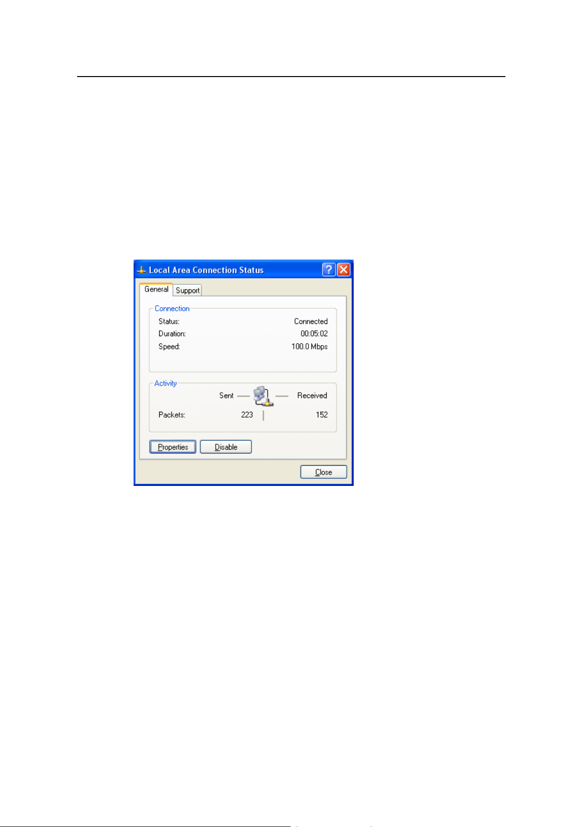
User Manual
Aolynk DR814Q ADSL2+ Broadband Router 7 Appendix - TCP/IP Protocol
7.2 Configuring TCP/IP
7.2.1 Specifying to Obtain an IP Address Automatically
If you are running Windows 98/ME/NT, refer to those described in section Figure 7-3 to
specify to obtain an IP address automatically. If yo u are running Windows 2000/XP,
perform the following operation.
1) Choose [Start/Settings/Control Panel] to open the [Control Panel] dialog box.
Double-click the Network Connection icon to open the [Network Connection]
dialog box and then double-click the Local Connection icon to open the [Local
Area Connection Status] dialog box (see Figure 7-5).
Figure 7-5 Local Area Connection Status dialog box
2) Click <Properties> to open the [Local Area Connection Properties] dialog box (see
Figure 7-6). Select the [General] tab and select Internet Protocol (TCP/IP) in the
[This connection uses the following items:] section, and then click <Properties> to
open the [Internet Protocol (TCP/IP) Properties] dialog box as shown in Figure
7-7.
87
Page 93
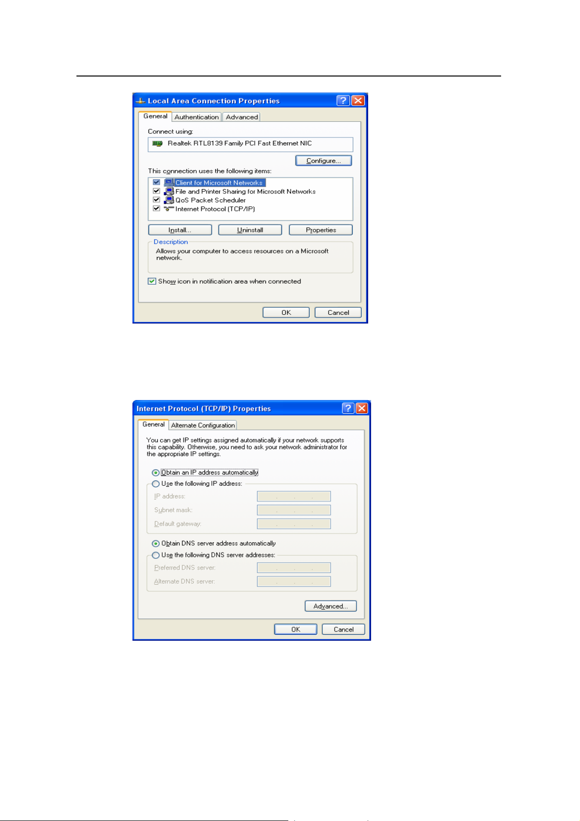
User Manual
Aolynk DR814Q ADSL2+ Broadband Router 7 Appendix - TCP/IP Protocol
Figure 7-6 Local Area Connection Properties
3) On the [General] tab page of the [Internet Protocol (TCP/IP) Properties] dialog box
select the Obtain an IP address automatically option and click <OK>.
Figure 7-7 Internet Protocol (TCP/IP) Properties dialog box
7.2.2 Specifying a Fixed IP Address
Since the DR814Q enables the DHCP by default, the PCs in the LAN can obtain related
information dynamically, thus there is no need to assign static IP addresses for PCs in
88
Page 94

User Manual
Aolynk DR814Q ADSL2+ Broadband Router 7 Appendix - TCP/IP Protocol
the LAN. But in some cases you still need to configure network settings for some or
even all the PCs on a network.
By default, the IP address of the Ethernet port of DR814Q is 192.168.1.1. Choose any
from 192.168.1.2 to 192.168.1.254 to make your PC in the same segment with
192.168.1.1/24. Follow the procedure suitable for your operating system to specify IP
addresses.
1) Specify the IP address of your PC.
z Windows 98/ME/NT: In the [TCP/IP Properties] dialog box (see Figure 7-4), select
the [IP Address] tab and select the Specify an IP address option.
z Windows 2000/XP: In the [Internet Protocol (TCP/IP) Properties] dialog box (see
Figure 7-7) select the [General] tab, and then the Use the following IP address
option. Type in the IP address and subnet mask in the corresponding fields and
click <OK>.
2) Specify the IP address of the gateway.
z Windows 98/ME/NT: In the [TCP/IP Properties] dialog box (see Figure 7-4) select
the [Gateway] tab. T ype in the default IP address of your DR814Q (192.168.1.1) i n
the [New gateway] text box and click <Add>.
z Windows 2000/XP: In the [Internet Protocol (TCP/IP) Properties] dialog box (see
Figure 7-7), select the [General] tab. Type in the default IP address of your
DR814Q (192.168.1.1) in the [Default gateway] text box and click <OK>.
3) Specify the IP address of the DNS server.
z Windows 98/ME/NT: In the [TCP/IP Properties] dialog box (see Figure 7-4), select
the [DNS configuration] tab and type in the default IP address of your DR814Q
(192.168.1.1) as the DNS server IP address in the corresponding field.
z Windows 2000/XP: In the [Internet Protocol (TCP/IP) Properties] dialog box (see
Figure 7-7) click <Advanced…> to open the [Advanced TCP/IP Configuration]
dialog box. Select the [DNS] tab and click <Add…>. T ype in the default IP address
of the DR814Q (192.168.1.1) in the [DNS server] field and click <Add>.
4) Making the settings take effect.
z Windows 98/ME/NT : Click <OK> and rest art your PC for the above settings to take
effect.
z Windows 2000/XP: Click <OK> to make the above settings to take effect.
89
Page 95

User Manual
Aolynk DR814Q ADSL2+ Broadband Router 8 Appendix - USB Configuration
8 Appendix - USB Configuration
8.1 Inst
alling USB Driver
Make sure the USB function of your PC operates properly.
The Microsoft Windows
installation procedure is based on Windows XP. Use it for refe
other operating system.
I.
Insert the driver CD into the CD-ROM of your PC.
The CD that comes with the DR814Q contains the USB driver.
II.
Plug one end of the USB cable into the USB port of the DR814Q, and the
other into the USB port of your PC.
The USB c
connector on the other end. Conn
DR814Q.
To ADSLEthernet router
able has a rectangular Type A connector on one end and a square Type B
98/98 SE/ME/2000/XP supports USB driver. The following
rence when running any
ect the Type A to your PC and the Type B to the
To PC
Figure 8-1 USB cable connector
90
Page 96

User Manual
Aolynk DR814Q ADSL2+ Broadband Router 8 Appendix - USB Configuration
III. The [Found New Hardware Wizard] dialog box appears (see Figure 8-2).
Select the Install the software automatically (Recommended) option and
click <Next> to proceed.
Figure 8-2 Find new hardware
IV. The PC searches the CD for the driver configuration file.When this file is
found, the PC begins to install the driver.
Figure 8-3 Install software
91
Page 97

User Manual
Aolynk DR814Q ADSL2+ Broadband Router 8 Appendix - USB Configuration
The dialog box (see Figure 8-4) appears during installation, warning that the device is
not compatible with Windows XP. Just click <Continue Anyway> to proceed. Microsoft
logo test
Figure 8-4 Microsoft logo test
V. The dialog box (see Figure 8-5) indicates the installation is complete. Click
<Finish> to exit the installation.
Figure 8-5 Complete the installation
8.2 Configuring IP Properties
After the USB driver installation is complete, you must configure the PC to place it in the
same subnet as the DR814Q USB port. Two options are available to configure the IP
properties:
92
Page 98

User Manual
Aolynk DR814Q ADSL2+ Broadband Router 8 Appendix - USB Configuration
z Your DR814Q can be a DHCP server to assign IP addresses to PCs in the LAN, so
you can specify your PC to obtain IP addre ss automati cally. Refer to section 7.2.1
“Specifying to Obtain an IP Address Automatically” for detailed information.
z If you want to specify a fixed IP address to the PC, follow the instructions in section
7.2.2 “Specifying a Fixed IP Address” a nd use the following information..
The USB port on the DR814Q is preconfigured with these properties:
IP address: 192.168.1.1
Subnet mask: 255.255.255.0
Therefore, your PC should be configured as the following:
IP address: 192.168.1.n (n is an integer ranging from 2 to 254)
Subnet mask: 255.255.255.0
93
Page 99

User Manual
Aolynk DR814Q ADSL2+ Broadband Router 9 Appendix - IP Address and Subnet Mask
9 Appendix - IP Addres
9.1 IP Address
Note:
z This section refers to the IP address of IPv4 (version 4 of the Internet Protocol) only
and the IP address of IPv6 is not covered.
This section describes the basic knowledge of binary numbers, bits, and bytes. z
An IP address, like the telephone number on the Internet, is used to identify the
individual node (a PC or network device) on the Internet. Every IP address contains
fou
r sets of numbers, each from 0 to 255 and separated by dots, for example
20.56.0.21 1.These numbers are called, from lef t to right, field 1, field 2, field 3, and field
4.
s and
Subnet Mask
9.1.1 Stru
The representation of four sets of digits separated by dots for IP address is called
dotted decimal notation.
cture of the IP Address
Like a telephone number, the IP address contains two components. For instan
first three digits of a seven-digit telephone number
telephone lines, whil
Similarly, an IP address contains two components:
z Network ID
Identify a specific network segment on the Intern
z Host ID
Identify a specific PC or device on the segment.
e the last four digits identify a specific line in this group.
94
identify a group with thousands of
et or the intranet.
ce, the
Page 100

User Manual
Aolynk DR814Q ADSL2+ Broadband Router 9 Appendix - IP Address and Subnet Mask
The starting part of every IP address i
length network I ds on th f the net er to se .2
of the
“Classe Addresses”). escri cture of the IP addre
T re of the IP address
s of IP
able 9-1 Structu
D depen
Table 9-1 d
s the network ID and the rest is the host Dither
e class o
bes the stru
work (ref ction 9.1
ss.
Class Field 1 Field 2 Field 3 Field 4
Class A Network ID Host ID
Class B Network ID Host ID
Class C Network ID Host ID
The following are some valid IP address examples:
Class A: 10.30.6.125 (network ID = 10, host ID= 30.6.125)
Class B: 129.88.16.49 (netwo
Class C: 192.60.201.11 (network ID = 192.60.201, host ID = 11)
9.1.2 Classes of IP Addresses
Three common IP addresses are of Cass A, B, and C. (Class D is for special use and is
beyond the scope of this discussion.) These classes have different uses and
characteristics.
The class A network is the largest on the Internet. This allows at least 16 million
per network. Such 126 class A networks can hold at least two billion PCs. These
enormous networks are quite suitable for the LAN or Internet fundamental
organizations such as Internet service provider (ISP).
The class B network is relatively smaller than the class A network, but it still allows
16,384 class B networks and 65,000 hosts in each class B network. This kind of
network is suitable for the large organization
The class C network is the smallest one. It allows o
ss
cla C networks and 254 hosts in each class C network. The LANs connecting to the
Inter lly of this class networks.
net are usua
rk ID = 129.88, host ID = 16.49)
hosts
s such as enterprises and governments.
ver two million (2,097,152 exactly)
Follo dress:
wing are the key points about the IP ad
z an IP address is to look at its number in
The easiest way to determine the class of
the field 1:
Class A: The number is from 1 to 126.
Class B: The number is from 128 to 191.
Class C: The
number is from 192 to 223.
(The numbers for special use are not given here.)
95
 Loading...