

Page 1

HUAWEI
Aolynk DR811/DR814 ADSL2+Broadband Router
User Manual
Page 2

Aolynk DR811/DR814 ADSL2+Broadband Router
User Manual
Manual Version
BOM
Huawei Technologies Co., Ltd. provides customers with comprehensive technical support
and service. If you purchase the products from the sales agent of Huawei Technologies Co.,
Ltd., please contact our sales agent. If you purchase the products from Huawei
Technologies Co., Ltd. directly, please feel free to contact our local office, customer care
center or company headquarters.
Huawei Technologies Co., Ltd.
Address: East of Liuhe Road, Zhijiang Science Park,
Hangzhou, P. R. China
Website: http://www.huawei-3com.com
T2-080127-20050126-C-1.00
3101A027
Email: soho@huawei-3com.com
Page 3

Copyright © 2005 Huawei Technologies Co., Ltd.
All Rights Reserved
No part of this manual may be reproduced or transmitted in any form or by any
means without prior written consent of Huawei Technologies Co., Ltd.
Trademarks
, HUAWEI, C&C08, EAST8000, HONET, , ViewPoint, INtess, ETS, DMC,
TELLIN, InfoLink, Netkey, Quidway, SYNLOCK, Radium, M900/M1800,
TELESIGHT, Quidview, Musa, Airbridge, Tellwin, Inmedia, VRP, DOPRA, iTELLIN,
HUAWEI OptiX, C&C08 iNET, NETENGINE, OptiX, iSite, U-SYS, iMUSE, OpenEye,
Lansway, SmartAX, infoX, TopEng are trademarks of Huawei Technologies Co.,
Ltd.
All other trademarks mentioned in this manual are the property of their respective
holders.
Notice
The information in this manual is subject to change without notice. Every effort has
been made in the preparation of this manual to ensure accuracy of the contents, but
all statements, information, and recommendations in this manual do not constitute
the warranty of any kind, express or implied.
Page 4

User Manual
Aolynk DR811/DR814 ADSL2+Broadband Router Table of Contents
Table of Contents
1 Introductions.............................................................................................................................3
1.1 Product Overview..............................................................................................................3
1.2 Appearance......................................................................................................................4
1.2.1 Front View..............................................................................................................4
1.2.2 Rear View...............................................................................................................5
1.3 Features...........................................................................................................................5
1.4 Parts Check......................................................................................................................6
2 Connecting Your Device...........................................................................................................7
2.1 Overview...........................................................................................................................7
2.2 Steps................................................................................................................................7
2.3 Finish................................................................................................................................8
3 Getting Started with the Web Pages........................................................................................9
3.1 Accessing the Web Pages.................................................................................................9
3.2 Web Page Layout...........................................................................................................11
3.3 Commonly Used Buttons.................................................................................................12
3.4 Testing Your Setup.........................................................................................................13
3.5 Default Device Settings...................................................................................................14
4 Web-based Management.........................................................................................................15
4.1 Quick Setup....................................................................................................................15
4.2 WAN Setting...................................................................................................................16
4.3 DNS Relay......................................................................................................................18
4.4 LAN Setting.....................................................................................................................19
4.5 DHCP.............................................................................................................................21
4.6 Route..............................................................................................................................22
4.7 Security Interface............................................................................................................25
4.8 DMZ Configuration..........................................................................................................28
4.9 Security Policy................................................................................................................30
4.10 Trigger..........................................................................................................................31
4.11 IDS...............................................................................................................................34
4.12 SNTP............................................................................................................................35
4.13 ZIPB.............................................................................................................................36
4.14 Password......................................................................................................................38
4.15 Remote Access.............................................................................................................38
4.16 Restart Router...............................................................................................................39
4.17 Configuration Backup/Restore.......................................................................................40
4.18 Upgrade........................................................................................................................42
4.19 Status...........................................................................................................................43
i
Page 5

User Manual
Aolynk DR811/DR814 ADSL2+Broadband Router Table of Contents
4.20 Log...............................................................................................................................45
4.21 PVC Scan.....................................................................................................................46
4.22 Save Configure.............................................................................................................47
5 Configuring Your Computers.................................................................................................48
5.1 Configuring Ethernet PCs................................................................................................48
5.1.1 Before You Begin..................................................................................................48
5.1.2 Windows® XP PCs...............................................................................................48
5.1.3 Windows 2000 PCs...............................................................................................49
5.1.4 Windows Me PCs..................................................................................................50
5.1.5 Windows 95, 98 PCs.............................................................................................50
5.1.6 Windows NT 4.0 Workstations..............................................................................51
5.1.7 Assigning Static Internet Information to Your PCs.................................................52
5.2 Configuring a PC Connected by USB Port.......................................................................53
5.2.1 Connecting a Computer to the USB Port by a USB cable......................................53
5.2.2 Installing the USB Driver.......................................................................................53
5.2.3 Configuring IP Properties on PC Connected by USB Port......................................56
6 IP Addresses, Network Masks, and Subnets.........................................................................57
6.1 IP Addresses..................................................................................................................57
6.1.1 Structure of an IP Address....................................................................................57
6.1.2 Network Classes...................................................................................................58
6.2 Subnet Masks.................................................................................................................58
7 Service Configuration.............................................................................................................60
7.1 Configuration Overview...................................................................................................60
7.2 PureBridge......................................................................................................................61
7.3 DHCP/StaticIP................................................................................................................62
7.4 IPoA................................................................................................................................62
7.5 PPPoA............................................................................................................................63
7.6 PPPoE............................................................................................................................63
8 Troubleshooting......................................................................................................................65
8.1 Troubleshooting Suggestions..........................................................................................65
8.2 Diagnosing Problem Using IP Utilities..............................................................................67
8.2.1 ping......................................................................................................................67
8.2.2 nslookup...............................................................................................................68
9 Appendix - Glossary................................................................................................................69
ii
Page 6

User Manual
Aolynk DR811/DR814 ADSL2+Broadband Router 1 Introductions
1 Introductions
1.1 Product Overview
DSL (Digital Subscriber Line) refers to a technology used to increase the data capacity
of standard twisted-pair wires that are generally used to connect most households to
the telephone network. In addition, this technology allows simultaneous voice and
high-speed data transmission over a single pair of telephone wires.
ADSL (Asymmetric Digital Subscriber Line), as its name indicates, is an asymmetrical
data transmission technology with higher traffic rates downstream and lower traffic
rates upstream. It is suitable for Internet users because information is usually
downloaded more often than uploaded, such as when surfing the web or downloading
files.
The Aolynk ADSL2+ router with embedded ADSL2+ technology brings up high-speed
internet access and remote connection features, which make it an ideal solution for
small businesses and SOHO users.
DR811/DR814 uses the ATM over ADSL2+ technology to communicate with the central
office providing the ADSL2+ service. As ATM PVC supports connections of various
types such as PPPoE, PPPoA, IPoA and bridge, Aolynk DR811/DR814 delivers great
networking flexibility and accommodates diversified requirements.
This type of router falls into 4 models as below.
Table 1-1 DR series of routers
Model Difference
DR814 ADSL2+ over POTS, 4 Ethernet ports
DR814I ADSL2+ over ISDN, 4 Ethernet ports
DR811 ADSL2+ over POTS, 1 Ethernet port
DR811I ADSL2+ over ISDN, 1 Ethernet port
3
Page 7
User Manual
Aolynk DR811/DR814 ADSL2+Broadband Router 1 Introductions
1.2 Appearance
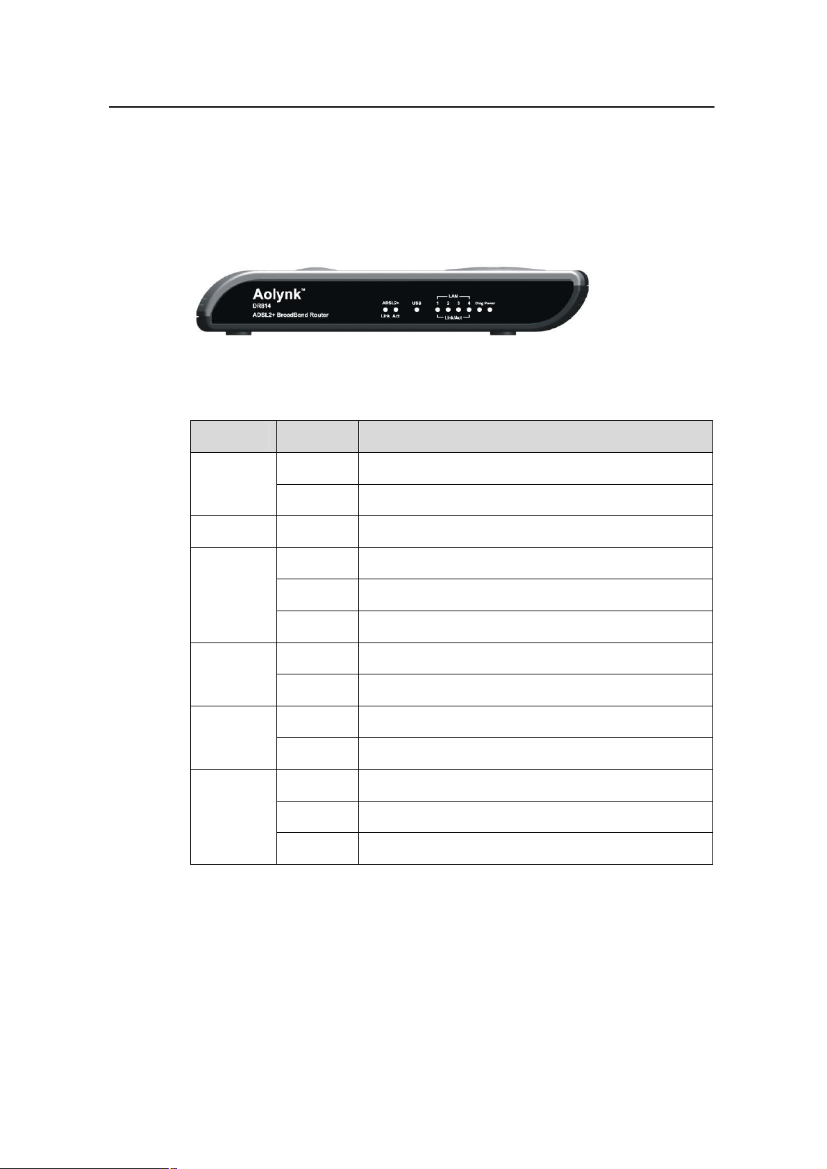
1.2.1 Front View
The front panel contains lights called LEDs that indicate the status of the unit.
Figure 1-1 Front panel
Table 1-2 LED description
LED Status Description
ON Power has been switched on and is working normally
Power
OFF Power is switched off or fails
Diag - For factory test only
ON ADSL loop is brought UP
Link
Act
USB
LAN1/2/3/4
(Only one
for DR811)
Blinking Starting up
OFF ADSL loop is down
Blinking Data is being transmitted or received through ADSL
OFF No data transmission activities present on the link
ON USB connection established
OFF No USB cable connected
ON Ethernet link is up
Blinking Ethernet interface is transmitting or receiving data
OFF No link is up
4
Page 8

User Manual
Aolynk DR811/DR814 ADSL2+Broadband Router 1 Introductions
1.2.2 Rear View
All cable connections to the ADSL router are made at the rear panel. A factory reset
button is located here as well.
Figure 1-2 Rear panel connections
Table 1-3 Port description
Interface Quantity Connector
Ethernet
USB 1
ADSL 1 RJ11
Reset 1 -
1.3 Features
1 (DR811)
4 (DR814)
RJ45
Series-B
Receptacle
Description
10/100Base-TX
10/100 Mbps auto-negotiation
MDI/MDIX auto-sensing
Compatible with IEEE802.3/802.3u
USB 1.1
ANSI T1.413 Issue 2
ITU G.992.1 AnnexA G.dmt
ITU G.992.2 G.lite
ITU G.992.3 ADSL2
ITU G.992.5 ADSL2+
Restoring to factory default settings (For
this purpose, you are required to hold
down the button for at least 5 seconds.)
The list below contains the main features of the device which make it excellent for
network connections.
Features include:
l Internal DSL modem for high-speed Internet access.
l Data rates up to 20Mbps for downstream and 1Mbps for upstream.
l Uses NAT to allow your entire network’s PCs to connect to the Internet using only
one (purchased) IP Address.
l Supports PPPoE that enables users to seamlessly connect to ISPs via the familiar
“dial-up” connection interface.
5
Page 9

User Manual
Aolynk DR811/DR814 ADSL2+Broadband Router 1 Introductions
l Built-in firewall for protecting your PCs from outside intruders.
l Supports DHCP client to acquire either a dynamic IP Address or a fixed IP
Address from the ISP.
l Built-in DHCP server for automatically assigning and managing LAN IP
addresses.
l USB port for connecting a USB-enabled PC.
l Zero Installation PPP Bridge (ZIPB), Network address translation (NAT), Firewall,
and IP filtering functions to provide security for your LAN.
l Network configuration through DHCP Server and DHCP Client.
l Services including IP route and DNS configuration and IP and DSL performance
monitoring.
l Allows multiple users to access the Internet at the same time by providing
maximum Internet utilization to multiple users sharing a single public IP Address.
l Allows users on Ethernet LAN to transfer data to each other.
l Friendly built-in web-based graphical user interface for easy configuration and
management through common web browsers.
1.4 Parts Check
Please check the arrived shipment against the following packing list, making sure all
the items are included and in good condition:
Table 1-4 Packing list
Aolynk ADSL2+ Broadband Router 1
Power adaptor 1
Telephone cables 1
Ethernet cable 1
USB cable 1
Screw and anchor 2
Quick Start manual 1
Driver & Manual CD 1
Interface Quantity
Quality card 1
6
Page 10
User Manual
Aolynk DR811/DR814 ADSL2+Broadband Router 2 Connecting Your Device
2 Connecting Your Device
2.1 Overview
This chapter provides basic instructions for connecting the ADSL router to a computer
or LAN.
This chapter assumes that you have already established a DSL service with your
Internet service provider (ISP). These instructions provide a basic configuration that
should be compatible with your home or small office network setup. Refer to the
subsequent chapters for additional configuration instructions.
When selecting a location for the ADSL router, allow ample clearance to access the
connections on the rear panel. For convenience, try to place the ADSL router near your
computer so you can monitor the LED indicators. Allow some space above the ADSL
router for ventilation to avoid problems with overheating.
The diagram below illustrates the hardware connections. Refer to the steps that follow
for specific instructions.
Aolynk ADSL2+ Router
Internet Wall plug
LINE
Splitter
ADSL PHONE
Desktop PC
Figure 2-1 Hardware connections
NoteBook
Telephone
2.2 Steps
1) Connect the DSL cable and optional telephone
7
Page 11

User Manual
Aolynk DR811/DR814 ADSL2+Broadband Router 2 Connecting Your Device
Two options are available for connecting the ADSL cable:
Option 1: Connect the ADSL port (same as a regular telephone port) on the rear panel
of DR811/DR814 to the wall jack of telephone line using the telephone cable.
Option 2: Connect the ADSL port on DR811/DR814 and a telephone set to a splitter,
and then the splitter to the wall jack of telephone line. Thus you may place phone calls
when accessing the Internet.
2) Connect the Ethernet cable
You can choose one of the following two options:
l If you are connecting a LAN hub to the ADSL router, attach one end of the
provided Ethernet cable to a regular hub port and the other to the one of the
Ethernet ports on the device.
l If you are connecting a single Ethernet computer to the ADSL router, attach it
directly to the one of the Ethernet ports on the device via an Ethernet cable.
3) Attach the power connector
Connect the power adapter to the Power connector on the back of the device and plug
the adapter into a wall outlet or power strip. DR811/DR814 has no power switch; so it is
powered on soon after the power cable is connected to the power jacket.
4) Configure your Ethernet PCs
You must also configure the Internet properties on your Ethernet PCs. Refer to ”5.1
Configuring Ethernet PCs”.
5) Install USB software and connect the USB cable
Only include this step if you want users to use the USB port.
You can attach a single computer to the device using a USB cable. The USB port is
useful if you have a USB-enabled PC that does not have a network interface card for
attaching to your Ethernet network.
Before attaching the USB cable, you must install a USB driver on your PC and
configure the computer. For complete instructions, refer to “5.2 Configuring a PC
Connected by USB Port.”
2.3 Finish
After setting up and configuring the device and PCs, you can log on to the device by
following the instructions in “ 3 Getting Started with
the Web Pages”.
8
Page 12

User Manual
Aolynk DR811/DR814 ADSL2+Broadband Router
3 Getting Started with
The ADSL router provides a series of web pages that function as an interface for
managing the device. These web pages enable you to configure the device to meet the
needs of your network. You can access them through your web browser from any PC
connected to the device via the LAN or USB port.
3 Getting Started with
the Web Pages
the Web Pages
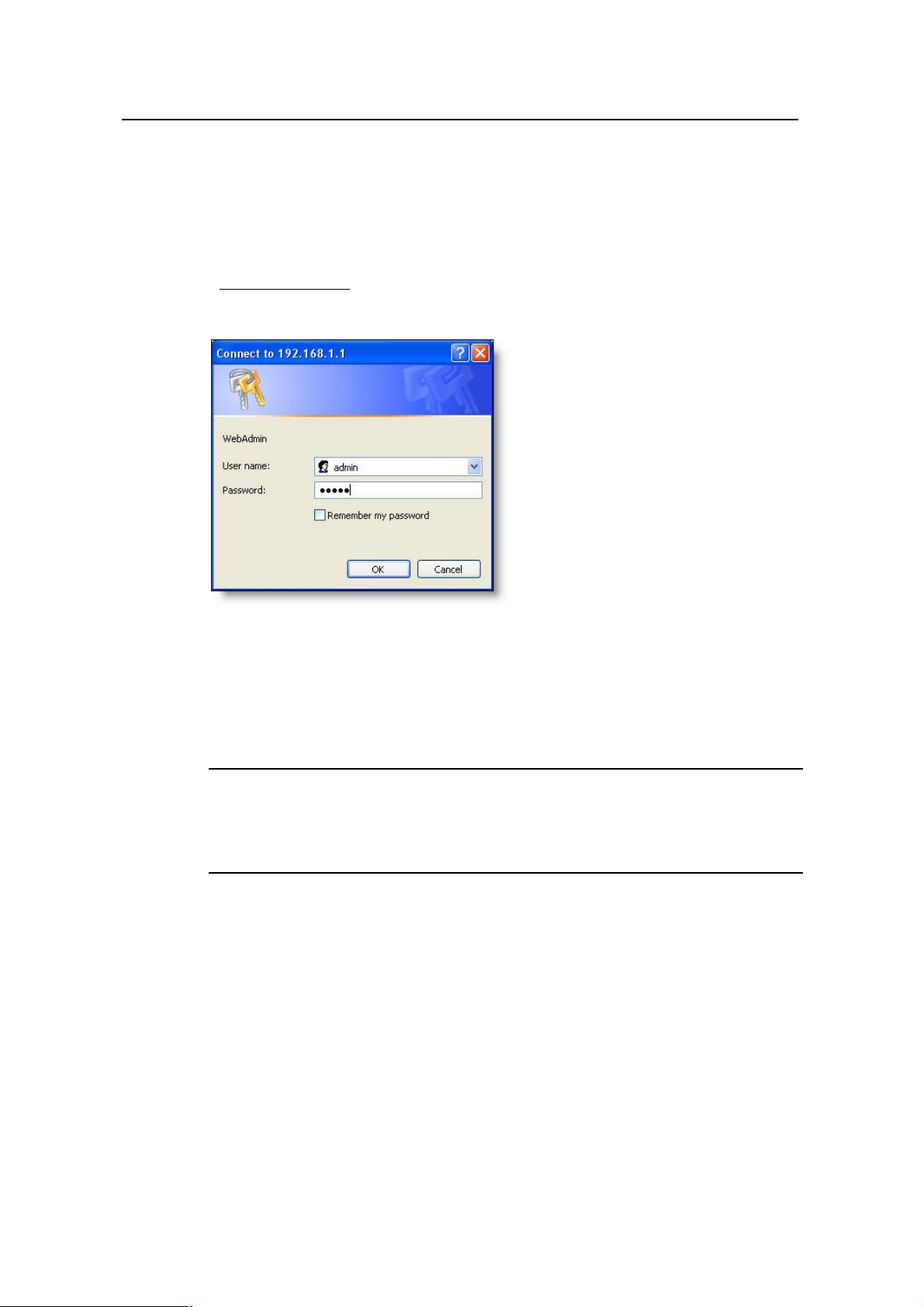
3.1 Accessing the Web Pages
To access the web pages, you need the following:
l A PC or laptop connected to the LAN or USB port on the device.
l A web browser installed on the PC. The minimum browser version requirement is
Internet Explorer v5.0 or Netscape v4. For the best display quality, use Internet
Explorer v6, or Netscape v6.1.
1. The default IP settings for the ADSL router are as follows:
IP address: 192.168.1.1
Subnet mask: 255.255.255.0
Before performing the above configurations on the ADSL router, first have the computer
set in the same subnet with the router. To do so, first install and enable the TCP/IP
protocol (refer to 5.1 Configuring Ethernet PCs), and then set an IP address and a
subnet mask, for example, 192.168.1.100 and 255.255.255.0. Make sure the IP
settings place the computer in the same subnet as the router.
2. If the browser software on the computer you are using is configured to use
a proxy server for Internet access, it is necessary to first disable the proxy
connection.
In Windows Internet Explorer, you can check if a proxy server is enabled using the
following procedure:
l In the Explorer Window, select and click on Tools->Internet Options to enter the
Internet Options window.
9
Page 13
User Manual
Aolynk DR811/DR814 ADSL2+Broadband Router
l In the Internet Options window, click the Connections tab and then click on the
LAN Settings button.
l Verify that the Use proxy server option is NOT checked. If it is checked, click in
the checked box to deselect the option and then click OK.
3. From any of the LAN computers, open the web browser, type
“http://192.168.1.1" in the web address (or location) box, and press [Enter]. A
login screen is displayed:
3 Getting Started with
the Web Pages
Figure 3-1 Login screen
4. Enter your user name and password. The first time you log into the program,
use the default user ID and password (admin and admin)
& Note:
You can change the password at any time. For the default user ID, admin, only the
password can be changed. Refer to 4.14 Password.
10
Page 14
User Manual
Aolynk DR811/DR814 ADSL2+Broadband Router
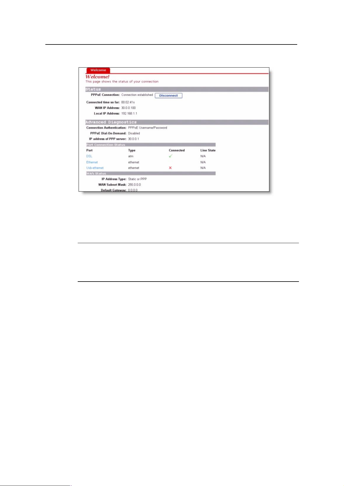
5. Click OK. The Welcome page is displayed:
3 Getting Started with
the Web Pages
Figure 3-2 The welcome page
This is the first page that is displayed each time you log in to the web pages.
& Note:
If you receive an error message or the Welcome page is not displayed, refer to “8.1
Troubleshooting Suggestions”.
3.2 Web Page Layout
The web pages provide information that allows you to configure your device. Links to
configuration pages are listed in the Main Menu on the left-hand side of the screen.
Click on an individual menu entry to display a page in the Main Frame, which is in the
white area.
11
Page 15
User Manual
Aolynk DR811/DR814 ADSL2+Broadband Router
Figure 3-3 The page layout
3 Getting Started with
the Web Pages
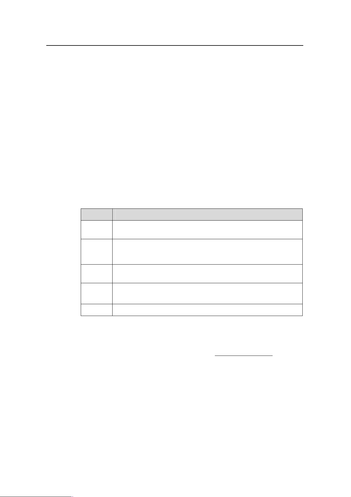
3.3 Commonly Used Buttons
The following buttons are used throughout the web pages:
Table 3-1 Buttons in the web pages
Button Function
These buttons appear at the end of a series of
configuration pages. Click on these buttons to confirm
and save the changes you have made.
This button appears on configuration pages. Click on
this button to restore the original settings.
This button appears on some pop-up configuration
pages. Click on this button to cancel the configurations
you have made, close the page, and return to the Main
Frame.
Radio buttons, which appear on many configuration
pages. Sometimes it may be necessary to select one
radio button from two or more available. You cannot
select more than one radio button at a time.
Drop-down list buttons, which appear on many
configuration pages. Click to select one.
12
Page 16
User Manual
Aolynk DR811/DR814 ADSL2+Broadband Router
The following terms are used throughout this guide in association with these buttons:
l Click – Position the cursor over a button, menu entry or link on the screen and click
the left mouse button. This performs an action, such as displaying a new page.
l Select – Usually used when describing which radio button to select from a list, or
which entry to select from a drop-down list. Position the cursor over the entry and
left-click to select it. This does not perform an action – you will also be required to
click on a button, menu entry or link in order to proceed.
3.4 Testing Your Setup
Once you have connected your hardware and configured your PCs, any computer on
your LAN should be able to use the device’s DSL connection to access the Internet.
To test the connection, connect a single Ethernet computer to the ADSL router, plug the
power cable to POWER socket of the device, wait for 1 minute and then verify that the
LEDs are illuminating as follows:
Table 3-2 Router LEDs
3 Getting Started with
the Web Pages
LED Behavior
Power Solid green to indicate that the power has been switched on. If this light
is not on, check the power cable attachment.
Link Flashing on/off while the ADSL line of the device is being activated.
After about 20-30 seconds, solid green to indicate that the device is
now communicating normally with the central office.
Act Flashing on/off while data is being transmitted. Going off indicates that
no data transmission happens.
LAN Solid green to indicate that the Ethernet link is up.
Flashing on/off while Ethernet interface is transmitting or receiving data.
USB Solid green to indicate that the USB connection is operational.
If the LEDs illuminate as expected, test your Internet connection from the LAN
computer (and from the USB computer, if applicable): Open your web browser, and
type the URL of any external website (such as http://www.yahoo.com). The LED
labeled ADSL Act should be blinking rapidly and may appear solid as the device
connects to the site.
If the LEDs do not illuminate as expected, you may need to configure your Internet
access settings using the information provided by your ISP. For details, refer to”4.2
WAN Setting”. If the LEDs still do not illuminate as expected, or the web page is not
displayed, refer to “8.1 Troubleshooting Suggestions”, or contact your ISP for
assistance.
13
Page 17

User Manual
Aolynk DR811/DR814 ADSL2+Broadband Router
3.5 Default Device Settings
In addition to handling the DSL connection to your ISP, the ADSL router can provide a
variety of services to your network. The device is pre-configured with default settings
for use with a typical home or small office network.
The table below lists some of the most important default settings; these and other
features are described fully in the subsequent chapters. If you are familiar with network
configuration, review these settings to verify that they meet the needs of your network.
Follow the instructions to change them if necessary. If you are unfamiliar with these
settings, try using the device without modification, or contact your ISP for assistance.
We strongly recommend that you contact your ISP prior to changing the default
configuration.
Table 3-3 Default settings
Option Default Setting Explanation/Instruction
3 Getting Started with
the Web Pages
DSL Port IP
Address
LAN Port IP
Address
DHCP
(Dynamic
Host
Configuratio
n Protocol)
NAT
(Network
Address
Translation)
Unnumbered
interface:
0.0.0.0
Subnet mask:
0.0.0.0
Assigned static IP
address:
192.168.1.1
Subnet mask:
255.255.255.0
DHCP server
enabled
following pool of
addresses:
192.168.1.2
to192.168.1.21
NAT enabled Your computers’ private IP addresses (refer to
with the
This is the temporary public IP address of the
WAN port on the device. It is an unnumbered
interface that is replaced as soon as your ISP
assigns a ‘real’ IP address. Refer to 7 Service
Configuration.
This is the IP address of the LAN port on the
device. The LAN port connects the device to
your Ethernet network. Typically, you will not
need to change this address. Refer to 6 IP
Addresses, Network Masks, and Subnets.
The ADSL router maintains a pool of private IP
addresses for dynamic assignment to your
LAN computers. To use this service, you must
have set up your computers to accept IP
information dynamically, as described in 5.1
Configuring Ethernet PCs.
DHCP above) will be translated to your public
IP address whenever they access the Internet.
Refer to 4.7 Security Interface.
DSL mode MultiMode Can be configured to multiple standard DSL
line modes.
Default
Username:P
assword
admin:admin
Use this account to login web-based setup
pages.
14
Page 18
User Manual
Aolynk DR811/DR814 ADSL2+Broadband Router 4 Web-based Management
4 Web-based Management
This chapter tells you how to use the web-based configuration and management
software to configure the ADSL router. It is organized basing on the order of the items in
the navigation tree to describe the functions of the ADSL router and their configuration
procedures.
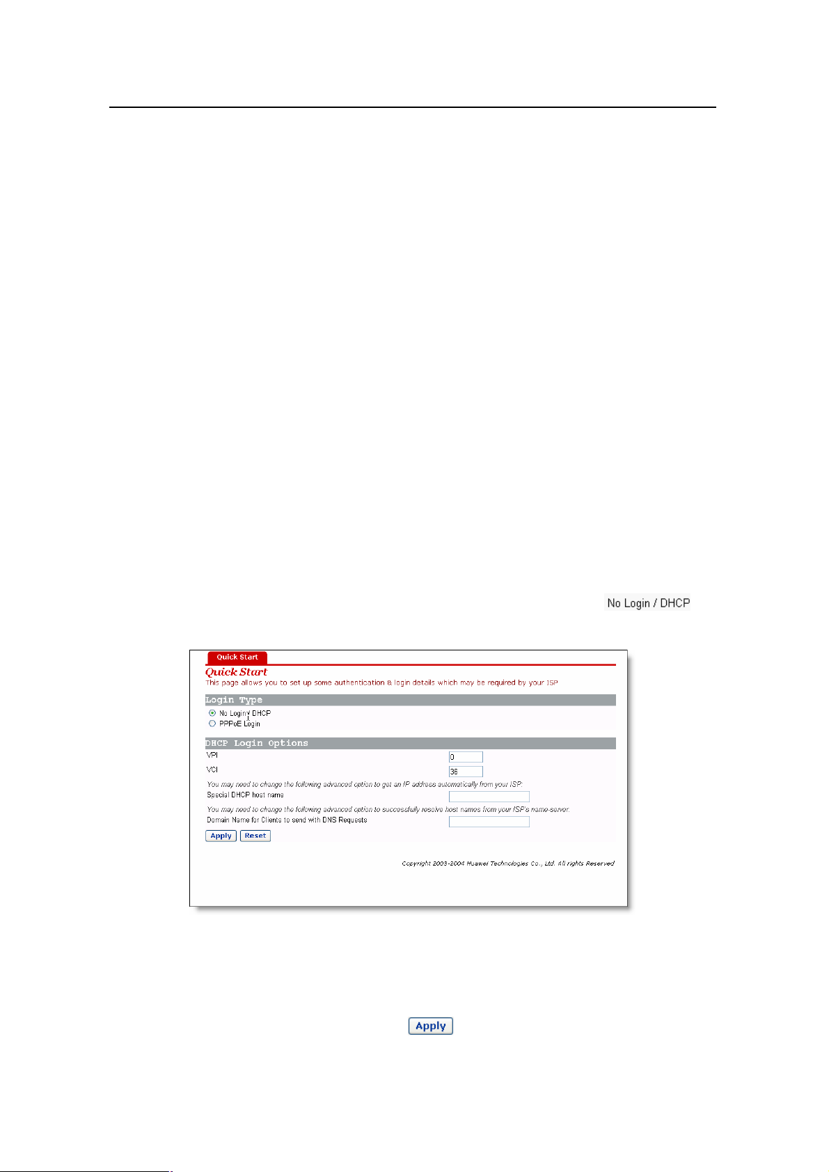
4.1 Quick Setup
Click Quick setup in the Main menu to open the Quick Start page.
This page allows you to:
l Choose the login type.
l Set up authentication & login details which may be required by your ISP.
To configure DHCP Login Options, click the radio button labeled , the
following page is displayed:
Figure 4-1 Quick setup page – no login
Enter VCI and VPI values as specified by your ISP; specify the Special DHCP host
name and/or Domain Name for Clients to send with DNS Requests, if needed
(usually not needed); then click the button.
15
Page 19
User Manual
Aolynk DR811/DR814 ADSL2+Broadband Router 4 Web-based Management
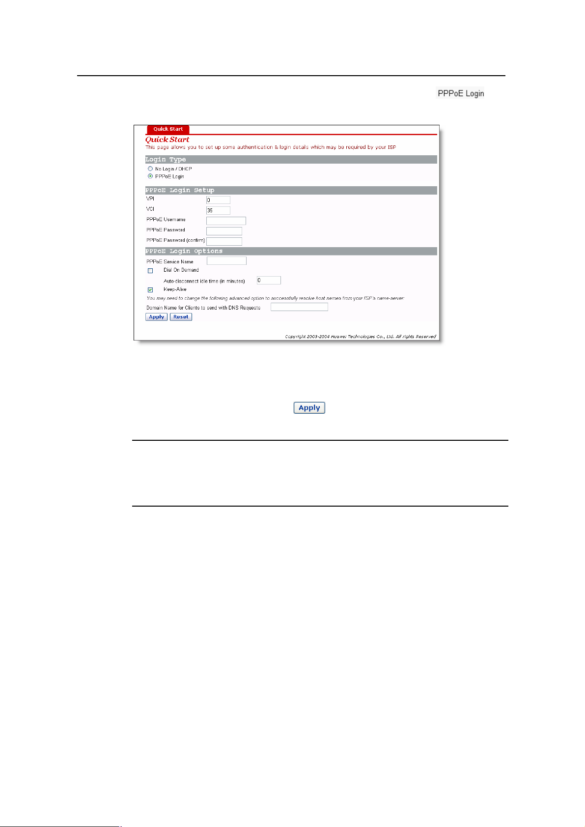
To configure PPPoE Login Options, click the radio button labeled , the
following page is displayed:
Figure 4-2 Quick setup page – PPPoE
Enter VCI and VPI values as specified by your ISP, the PPPoE login authentication info
and configuration, and then click the button.
& Note:
Avoid using the same pair of VPI and VCI values for configuring DHCP and PPPoE
login options.
4.2 WAN Setting
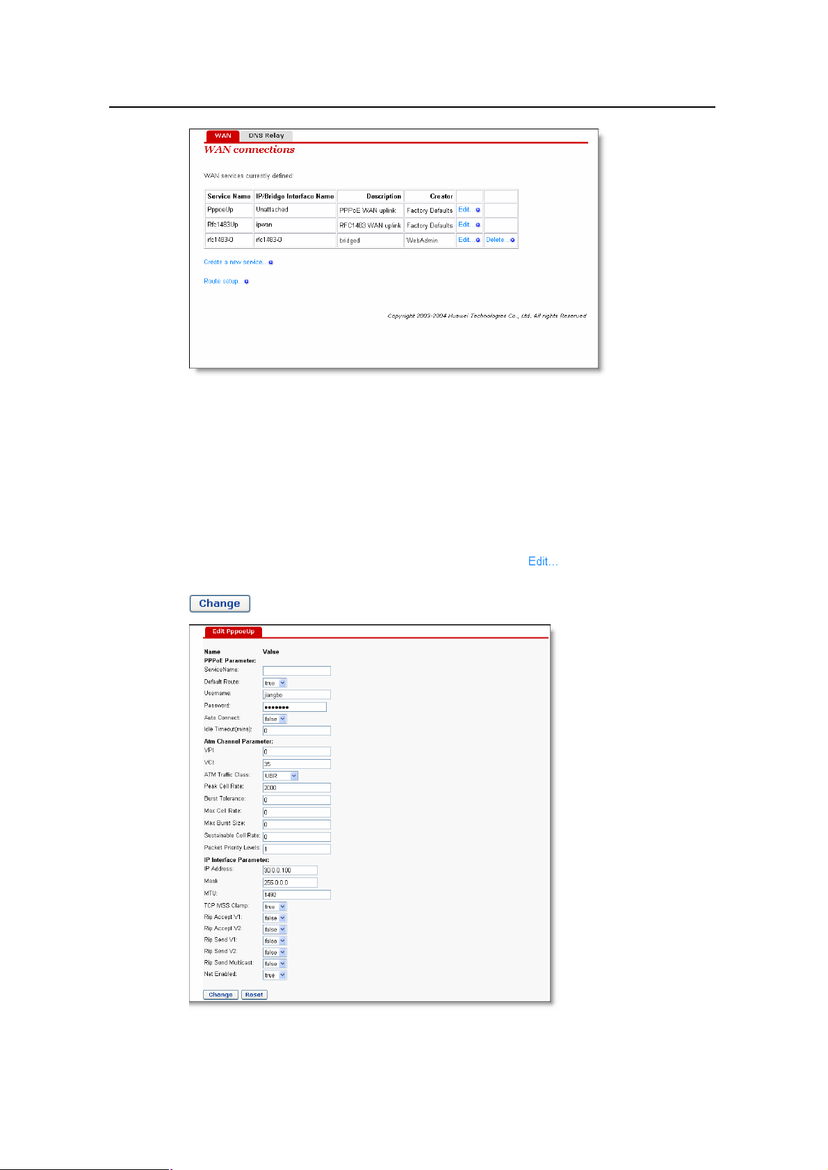
Click WAN Setup in the Main menu and choose the WAN tab in the Main Frame to
open the WAN Connection Configuration page.
16
Page 20
User Manual
Aolynk DR811/DR814 ADSL2+Broadband Router 4 Web-based Management
Figure 4-3 WAN setting
This page allows you to:
l Edit an existing WAN service present in the WAN service list.
l Delete a WAN service present in the WAN service list.
l Add a new WAN service to the WAN service list.
l Edit a route.
To edit a present WAN service, click the corresponding label to see the edit page
as the following one. If needed, change the values of the service options then click the
button.
Figure 4-4 Edit WAN settings
17
Page 21
User Manual
Aolynk DR811/DR814 ADSL2+Broadband Router 4 Web-based Management
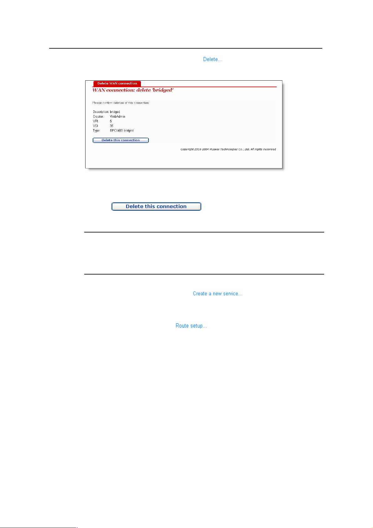
To delete a present WAN service, click the label that corresponds to this item to
open the web page Delete WAN connection.
Figure 4-5 Delete WAN settings
Click the button to delete the service.
& Note:
Only services created by the user can be edited. The first two items in the WAN service
list are default services.
To add a new WAN service, click the label to open the web page
WAN Connection: create service. To add a new service, refer to 7 Service
Configuration.
To configure the routes, click the label to open the route configuration page.
To edit routes, refer to 4.6 Route.
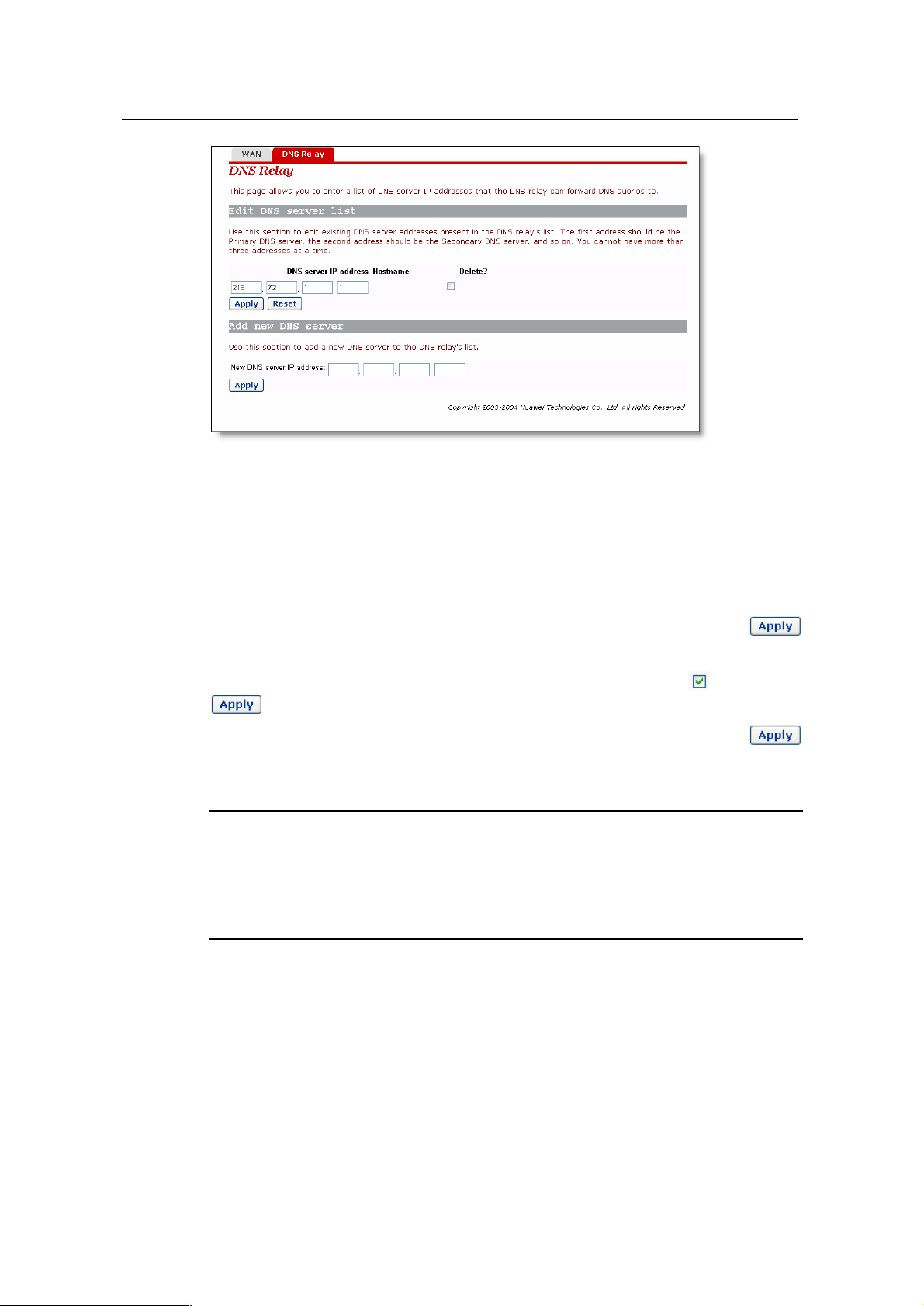
4.3 DNS Relay
A DNS relay server forwards the requests received from the PCs on the LAN to the
actual DNS servers. When the unit is configured as a DNS relay server, users will not
need to change the DNS server IP address on their PC whenever their ISP changes
DNS servers, or when the user connects to a different ISP.
Click WAN Setup in the Main menu and choose the DNS Relay tab in the Main Frame
to open the DNS configuration page.
18
Page 22
User Manual
Aolynk DR811/DR814 ADSL2+Broadband Router 4 Web-based Management
Figure 4-6 DNS relay
This page allows you to:
l Edit a DNS server address present in the DNS relay list.
l Add a new DNS server to the DNS relay list.
l Delete a present DSN server.
To edit a present DNS server item, modify the server’s IP address and click the
button.
To delete a present DNS server, check the corresponding check box and click the
button.
To add a new DNS server, enter the server’s IP address, and then click the
button. For more details about IP address, refer to 6.1 IP Addresses.
& Note:
In DNS Server list, the first address should correspond to the Primary DNS server; the
second address should correspond to the Secondary DNS server, and so on. You
cannot have more than three addresses at a time.
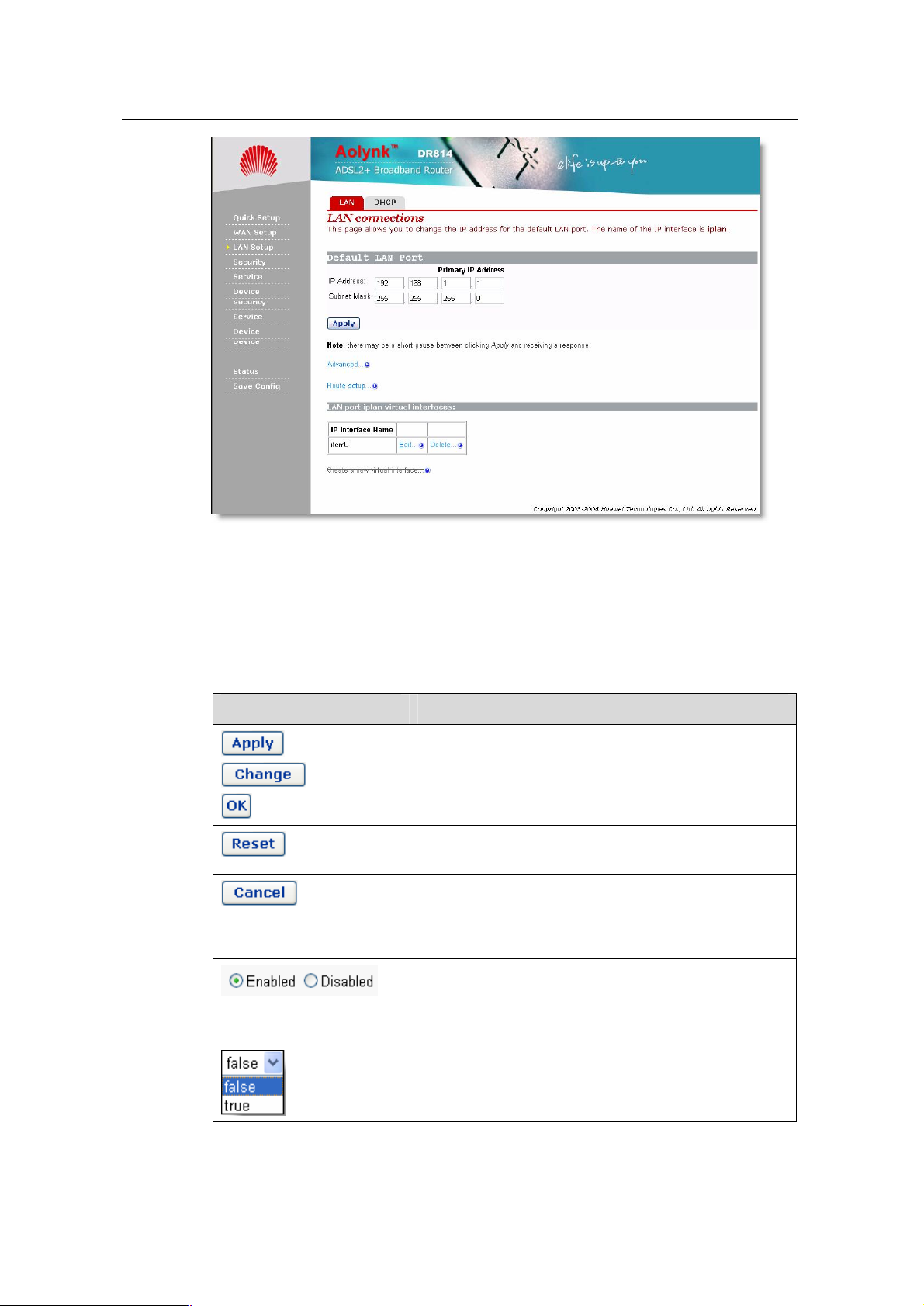
4.4 LAN Setting
Click LAN Setup in the Main menu and choose the LAN tab in the Main Frame to open
the LAN configuration page.
19
Page 23

User Manual
Aolynk DR811/DR814 ADSL2+Broadband Router 4 Web-based Management
Figure 4-7 LAN setting
This page allows you to:
l View and modify the LAN IP address and subnet mask.
l Advanced configuration about LAN setting.
l Edit a route.
l Create a virtual interface.
l Edit the current virtual interface.
l Delete the current virtual interface.
To modify the LAN IP address and subnet mask, enter the IP address and/or subnet
mask, and then click the button. For more details about IP address, refer to 6.1
IP Addresses.
To configure the advanced attributes about LAN settings, click the label to
open the web page Edit iplan. If needed, change the values of options, and then click
the button.
20
Page 24

User Manual
Aolynk DR811/DR814 ADSL2+Broadband Router 4 Web-based Management
Figure 4-8 Edit iplan interface
To configure the routes, click the label to open the route configuration page.
To edit routes, refer to 4.6 Route.
To create a new virtual interface, click Create a new virtual interface to enter the
Create virtual interface page. Input an IP address for the virtual interface and/or a
subnet (Note that the IP address of the virtual interface must not belong to the same
subnet as that of the LAN interface), and then press Apply to enable it. Refer to 6.1 IP
Addresses for more information about IP address. The virtual interface created here
can be used for DMZ configuration. Refer to 4.8 DMZ Configuration for more
information.
To edit the current virtual interface, click <Edit…>. Then in the new page, change the
settings if necessary, and press <change> to confirm your changes.
To delete the current virtual interface, click <Delete…>. Then in the new page, click
<Delete this connection…> to confirm your deletion.
& Note:
Only after the user has created a virtual interface can you create a new security
interface in Security Interface Configuration page, refer to 4.7 Security Interface for
more information.
4.5 DHCP
As a DHCP server, the unit maintains a pool of IP addresses and distributes them to
LAN hosts whenever those hosts are switched on.
21
Page 25

User Manual
Aolynk DR811/DR814 ADSL2+Broadband Router 4 Web-based Management
Click LAN Setup in the Main menu and choose the DHCP tab in the Main Frame to
open the DHCP configuration page.
Figure 4-9 DHCP setting
This page allows you to:
l Enable/disable the DHCP server.
l Assign the DHCP server address pool.
If the DHCP server is currently disabled, you may click the button to enable it.
If the DHCP server is currently enabled, you may click the button to disable
it.
The DHCP server (if enabled) will use the address pool defined in this page to provide
IP addresses to requesting DHCP clients. You may check the Use the default range
box to assign a suitable default IP address pool on this subnet (recommended). If
needed, you can change the DHCP address pool manually, but you must uncheck the
Use the default range box in the meantime.
To change the DHCP address pool manually, enter the start IP address and/or end IP
address, and then click the button. For more details about IP address, refer to 6.1
IP Addresses.
Enter a DNS suffix in the Local domain name box as needed. This option is usually
used for small- to moderate-sized enterprises. Common home users do not need to set
it.
4.6 Route
This option allows you to create static IP routes to destination addresses via an IP
interface name or a gateway address.
To access the route configuration page, follow anyone of these steps:
22
Page 26

User Manual
Aolynk DR811/DR814 ADSL2+Broadband Router 4 Web-based Management
l Click WAN Setup in the Main menu and choose the WAN tab in the Main Frame
to open the WAN connection configuration page, and then click the
label to open the route configuration page.
l Click LAN Setup in the Main menu and choose the LAN tab in the Main Frame to
open the LAN configuration page, and then click the label to open the
route configuration page.
l Click Status in the Main menu and choose the Status tab in the Main Frame to
open the status page, and then click the label to open the route
configuration page.
Figure 4-10 Routes configuration
This page allows you to:
l View the information about existing routes.
l Edit a route present in the route list.
l Add a new route to the DNS relay's list.
l Delete a present route.
This page lists the following information about existing routes:
l Whether the route is valid or invalid .
l Destination IP address.
l Gateway address.
l Netmask.
l Whether the route is advertised via RIP (true or false)
To edit the destination address, gateway address, netmask and advertise status of a
route, click in the relevant text box, update the information then click the button.
To edit the cost or interface settings for the route, click the label to
open the web page advanced setting.
23
Page 27

User Manual
Aolynk DR811/DR814 ADSL2+Broadband Router 4 Web-based Management
Figure 4-11 Advanced setting of routes
Update the relevant values of route options, and then click the button.
To delete an existing route item, check the corresponding check box and click the
button.
To add a new route item, click the label to open the web page IP
V4Route. Enter the values of route options, and then click the button. Click the
button to abort this action and return to the route configuration page.
Figure 4-12 Create routes
24
Page 28

User Manual
Aolynk DR811/DR814 ADSL2+Broadband Router 4 Web-based Management
& Note:
For DHCP or fixed IP service, the address of the next hop must be entered in the
Gateway box (the box must not be left blank), while Interface can be the default None
or any other value. For other services (i.e. IPoA, PPPoA, PPPoE), either Interface or
Gateway must be specified with a value; if both of them are configured, only Interface
takes effect.
4.7 Security Interface
Click Security in the Main menu and select the Interface tab in the Main Frame to
open the Security Interface Configuration page.
Figure 4-13 Security interface
This page allows you to:
l Enable/disable the security.
l Enable/disable the firewall.
l Enable/disable the intrusion detection.
l Assign the security level.
l Add/delete a security interface.
l Enable/disable NAT to internal interfaces.
l NAT configuration.
To enable/disable the firewall, click the radio button labeled Enabled/Disabled
corresponding to Firewall, then click the button.
To enable/disable the intrusion detection, click the radio button labeled
Enabled/Disabled corresponding to Intrusion Detection, then click the
button.
25
Page 29

User Manual
Aolynk DR811/DR814 ADSL2+Broadband Router 4 Web-based Management
To enable/disable the security, click the radio button labeled Enabled/Disabled
corresponding to Security, then click the button.
& Note:
Firewall, intrusion detection and NAT can only be enabled if security is enabled.
Firewall, intrusion detection and NAT must be disabled if security is disabled.
The security level drop-down list contains entries defined as below, in which None level
indicates that Internet users are not allowed to access the intranet, High level indicates
that Internet users have part of the intranet services-access authority, medium level
indicates even higher authority, and Low level indicates the highest authority. To set the
proper security level, position the cursor over the entry and left-click to select it, and
then click the button.
& Note:
Firewall must be enabled before security level can be configured.
To add a new security interface, click the label to open the web page Add
Interface. Make sure that you have created a virtual interface before doing so. Refer to
4.4 LAN Setting for the way to create a virtual interface.
Figure 4-14 Security – add interface
26
Page 30

User Manual
Aolynk DR811/DR814 ADSL2+Broadband Router 4 Web-based Management
Click on the Name drop-down list and select the LAN service that you want to base
your security interface on. Only IP interfaces that have not been assigned a security
type are displayed.
Click on the Interface Type drop-down list and specify what kind of interface it is
depending on, that is, how it connects to the network: external, internal or DMZ.
Click the button. The Security page is displayed, The Security Interfaces table
displays information about each existing security interface, including the interface that
you have just configured.
To delete a present security interface, click the corresponding label to
open the web page Delete Interface, and click the button.
Figure 4-15 Security – delete interface
If the NAT is currently disabled, you may click the
button to enable it. If the NAT is currently
enabled, you may click the button to
disable it.
To perform advanced NAT configuration, click the label to
open the web page Advanced NAT Configuration. If needed, modify the Global
Address Pools and Reserved Mappings configurations.
27
Page 31

User Manual
Aolynk DR811/DR814 ADSL2+Broadband Router 4 Web-based Management
Figure 4-16 Advanced NAT configuration
& Note:
NAT can only be configured when at least one of the following pairs of interface types
are defined:
l external and internal
l external and DMZ
l DMZ and internal
& Note:
l Advanced NAT configuration can only be performed when the NAT to internal
interfaces is enabled.
l Security must be enabled to configure NAT.
4.8 DMZ Configuration
The DMZ feature that DR series routers provide allows hosts in a DMZ zone to perform
unlimited bi-directional communication with other Internet users or servers. This not
only provides a security shelter for internal hosts to normally access the Internet, but
also satisfies the needs to install servers in LANs for services such as FTP and web to
fulfill two-way communication that small- to moderate-sized enterprises call for.
Follow these steps to configure DMZ:
28
Page 32

User Manual
Aolynk DR811/DR814 ADSL2+Broadband Router 4 Web-based Management
Figure 4-17 DMZ configuration
l Create a virtual interface as instructed in 4.4 LAN Setting, enter the following
parameters in the corresponding items and click the <Apply> button:
Figure 4-18 Create a virtual interface
The result will appear in a web page, showing that a virtual interface with the name of
item0 has been added into the list.
l Add a security interface as instructed in 4.7 Security Interface, make settings
according to the following figure, and then click the <Apply> button:
Figure 4-19 Add a security interface
29
Page 33

User Manual
Aolynk DR811/DR814 ADSL2+Broadband Router 4 Web-based Management
Where item0 is the virtual interface added at the last step.
l Then, enter the Port Filters page of external-dmz (refer to 4.9 Security Policy),
configure to ensure that users under the external interface can access the Internet
services the DMZ zone specifies such as http, ftp, telnet, and so on. Meanwhile,
configure port filtering policies for external-internal to disable users under the
external interface from accessing host services under the internal interface.
l Finally, configure to allow DMZ hosts to access DMZ zone. Make sure the IP
address of the DMZ host is in the same segment as that of the above configured
virtual interface (for example, configure the IP address as 172.16.1.100, the mask
as 255.255.0.0), enable the corresponding Internet service, and then connect the
host to the LAN port of the router, and configure the corresponding virtual server.
As such, DMZ is completely and securely configured.
4.9 Security Policy
A policy is the collective term for the rules that apply to incoming and outgoing traffic
between two interface types. Firewall must be enabled before you can create policies.
Click Security in the Main menu and choose the Policy tab in the Main Frame to open
the Security Policy Configuration page.
Figure 4-20 Security policy configuration
This page allows you to:
l Edit a security policy present in the Current Security Policies list.
To edit an existing security policy, click the label to open the web page Port
Filter to configure the port filter rules, and/or click the label to open the
web page Host Validators to configure the host validator rules.
30
Page 34

User Manual
Aolynk DR811/DR814 ADSL2+Broadband Router 4 Web-based Management
Figure 4-21 Firewall port
Figure 4-22 Host validator
& Definition:
A host validator can be used to restrict data streams from a WAN interface to a LAN
interface or from a LAN interface to a WAN interface.
& Note:
Security policies take effect only after the firewall starts.
4.10 Trigger
Security triggers are used to deal with application protocols that create separate
sessions. Some application protocols, such as Netmeeting, open secondary
connections during normal operations. Triggers tell the security mechanism to expect
31
Page 35

User Manual
Aolynk DR811/DR814 ADSL2+Broadband Router 4 Web-based Management
these secondary sessions and instruct it how to handle them. Triggers handle the
situation dynamically, allowing the secondary sessions only when appropriate.
Click Security in the Main menu and choose the Trigger tab in the Main Frame to open
the Security Trigger Configuration page.
Figure 4-23 Security trigger
This page allows you to:
l View security triggers present in the current security trigger list.
l Create a new trigger and add it to the current security trigger list.
l Delete an existing security trigger.
To create a new security trigger, click the label to open the web page Add
Trigger.
Figure 4-24 Add trigger
Configure the trigger as follows:
32
Page 36

User Manual
Aolynk DR811/DR814 ADSL2+Broadband Router 4 Web-based Management
l Transport Type: select a transport type from the drop-down list, depending on
whether you are adding a trigger for a TCP or a UDP application.
l Port Number Start: type the start of the trigger port range that the primary session
uses.
l Port Number End: type the end of the trigger port range that the primary session
uses.
l Secondary Port Number Start: type the start of the trigger port range that the
secondary session uses.
l Secondary Port Number End: type the end of the trigger port range that the
secondary session uses.
l Allow Multiple Hosts: select Allow if you want a secondary session to be
initiated to/from different remote hosts. Select Block if you want a secondary
session to be initiated only to/from the same remote host.
l Max Activity Interval: type the maximum interval time (in milliseconds) between
the use of secondary port sessions.
l Enable Session Chaining: select Allow or Block depending on whether you
want to allow multi-level TCP session chaining.
l Enable UDP Session Chaining: select Allow or Block depending on whether
you want to allow multi-level UDP and TCP session chaining. Enable Session
Chaining must be set to Allow for this option to work.
l Binary Address Replacement: select Allow or Block depending on whether you
want to use binary address replacement on an existing trigger.
l Address Translation Type: specify what type of address replacement is set on a
trigger. Binary Address Replacement must be set to Allow for this option to
work.
Once you have configured the trigger, click the button. The Security Trigger
Configuration page is displayed, containing details of the trigger that you have just
configured.
To delete an existing security trigger, click the corresponding label to open the
web page Delete Triggers.
33
Page 37

User Manual
Aolynk DR811/DR814 ADSL2+Broadband Router 4 Web-based Management
Figure 4-25 Delete trigger
Click the button to delete this trigger.
4.11 IDS
The IDS Settings protect your network from the following kinds of attacks:
l DOS (Denial of Service).
l Port Scanning.
l Web Spoofing.
IDS also implements blacklisting. This stops external hosts that try to attack the
network from accessing your device for a specific time limit.
Click Security in the Main menu and choose the IDS tab in the Main Frame to open the
Firewall Configure Intrusion Detection page.
34
Page 38

User Manual
Aolynk DR811/DR814 ADSL2+Broadband Router 4 Web-based Management
Figure 4-26 IDS setting
This page allows you to:
l Modify the current IDS configurations.
l Clear the blacklist.
To change the current IDS configurations, enter the relevant values of IDS options, and
then click the button.
To clear the blacklist, click the button.
& Note:
By default, the Security module is enabled.
4.12 SNTP
Configuring your device as an SNTP client allows you to obtain accurate time/date
information from an associated SNTP server. If you are not attached to an SNTP server,
you can set the time/date on your own device instead.
Click Service in the Main menu and choose the SNTP tab in the Main Frame to open
the SNTP configuration page.
35
Page 39

User Manual
Aolynk DR811/DR814 ADSL2+Broadband Router 4 Web-based Management
Figure 4-27 SNTP setting
This page allows you to:
l View the current status about system time configuration.
l Configure NTP servers on the Internet to which the ADSL router is able to
To synchronize the local time with the SNTP server, go to the top of the page and click
the button.
To add a NTP Server, enter the IP Address or the domain name of the SNTP server at
the SNTP Server Configuration Parameters section of the page and click on the
button.
To delete an existing NTP Server, click the corresponding button.
To set the timezone, position the cursor over the relevant entry from the timezone
drop-down list and left-click to select it, and then click the button.
4.13 ZIPB
ZIPB stands for "Zero Installation PPP Bridge". It is a way to ensure that a home user
can be assigned a public IP address through the router, and to resolve the problem that
all SOHO routers with NAT enabled cause part of the application unable to function
normally.
synchronize its internal clock.
Click Service in the Main menu and choose the ZIPB tab in the Main Frame to open the
ZIPB configuration page.
36
Page 40

User Manual
Aolynk DR811/DR814 ADSL2+Broadband Router 4 Web-based Management
Figure 4-28 ZIPB setting
This page allows you to:
l Enable/disable the ZIPB mode.
l Perform advanced ZIPB configurations.
If the ZIPB is currently disabled, you may click the button to enable it. If the
ZIPB is currently enabled, you may click the button to disable it.
To select which of your LAN computers will use the public IP address, click on the
drop-down list below Choose which computer will use the public IP address,
position the cursor over the entry and left-click to select a LAN computer, and then click
the button.
To perform advanced ZIPB configurations, proceed according to the following steps:
l Select the LAN interface that ZIPB will run on: click on the LAN interface drop
down list and select an interface.
l Select the WAN interface that ZIPB will run on: click on the WAN interface drop
down list and select an interface.
Once you have configured ZIPB, click the button.
& Note:
Make ensure that ZIPB is disabled before you configure ZIPB. Edit the configurations
and click OK, the new configuration will take effect after you enable ZIPB.
Configuration changes on ZIPB will not be kept permanently, so you need to configure
it again whenever the Router is restarted. In this way, remember to renew the IP
address of the ZIPB host first.
37
Page 41

User Manual
Aolynk DR811/DR814 ADSL2+Broadband Router 4 Web-based Management
4.14 Password
You can restrict access to your device’s web pages using password protection. With
password protection enabled, users must enter a username and a password before
gaining access to the web pages.
By default, the username and password are set as follows:
Username: admin
Password: admin
For more information, refer to 3 Getting Started with
the Web Pages.
& Note:
For the default user ID admin, only the password can be changed.
Non-authorized users may try to guess your username and password. They will find it
easier to guess the default username and password than to guess your own unique
username and password. We recommend that you change the default password to
your own unique setting.
Click Device in the Main menu and choose the Password tab in the Main Frame to
open the password configuration page.
Figure 4-29 Modify password
This page allows you to:
l Change the password of the default user: admin.
To change the password, enter the new password, and then click the button.
4.15 Remote Access
Click Device in the Main menu and choose the Remote tab in the Main Frame to open
the remote administration configuration page.
This page allows you to:
38
Page 42

User Manual
Aolynk DR811/DR814 ADSL2+Broadband Router 4 Web-based Management
l Enable/disable the remote administration.
l Set the value of idle timeout (if enabled).
If the remote administration is currently disabled, the following page is displayed .To
enable the remote access, enter the idle timeout then click the button.
Figure 4-30 Remote access
If the remote administration is currently enabled, the following page is displayed.
Whenever the remote administration is enabled, the system starts for timing; as soon
the timer reaches the set timeout time, the remote connection is taken down. To disable
the remote access, click the button.
Figure 4-31 Disable remote access
4.16 Restart Router
Click Device in the Main menu and choose the Restart tab in the Main Frame to open
the restart page.
Figure 4-32 Restart
39
Page 43

User Manual
Aolynk DR811/DR814 ADSL2+Broadband Router 4 Web-based Management
This page allows you to:
l Restart the ADSL router.
l Reset all configurations to default settings and restart the ADSL router.
If you would like to reset all configurations to default settings, check the Restart to
factory default setting box . Click the button to restart the ADSL router.
& Note:
After clicking the restart button, wait for several seconds to let the system restart.
4.17 Configuration Backup/Restore
Click Device in the Main menu and choose the Backup tab in the Main Frame to open
the configuration management page.
Figure 4-33 Backup/restore configuration
This page allows you to:
l Backup the current configuration to a file on your computer.
l Restore configuration from a previously saved file.
To backup the current configuration, click the button, the following page is
displayed.
40
Page 44

User Manual
Aolynk DR811/DR814 ADSL2+Broadband Router 4 Web-based Management
Figure 4-34 Download configuration file
Click the button to pop up the following window:
Figure 4-35 Save configuration file
Enter a proper filename, and then click the button to backup the current
configuration to the file.
To restore configuration from a previously saved file, click the
button to pop up the Choose file window.
41
Page 45

User Manual
Aolynk DR811/DR814 ADSL2+Broadband Router 4 Web-based Management
Figure 4-36 Select backup file
Click the button to open the selected configuration file, the following page is
displayed. Click the button to restore configuration from the selected file.
Figure 4-37 Restore configuration
4.18 Upgrade
Click Device in the Main menu and choose the Upgrade tab in the Main Frame to open
the firmware upgrade page.
42
Page 46

User Manual
Aolynk DR811/DR814 ADSL2+Broadband Router 4 Web-based Management
Figure 4-38 Firmware upgrade
This page allows you to update the system software on your network device from an
image file which may be obtained from Huawei support website.
Enter the path to the image file location in the text box or click the
button to locate the image file.
Click the button to open the selected firmware image file.
Click the button to update the system software on the ADSL router with the
selected image file.
& Note:
The upgrade process takes about 2 minutes to complete, and the ADSL router will
reboot.
After the router reboots, restore the configuration to the factory settings at first to make
sure that the current configuration file matches!
Click the “Huawei” hyperlink to visit the support web site from where the update image
file may be obtained.
4.19 Status
Click Status in the Main menu and choose the Status tab in the Main Frame to open
the Status page.
43
Page 47

User Manual
Aolynk DR811/DR814 ADSL2+Broadband Router 4 Web-based Management
Figure 4-39 Status page
The Status page displays useful information about the setup of the ADSL router,
including:
l Details of the ADSL router’s Internet access settings
l Some important system information (hardware information, version information)
l Routing table
l Current DSL state and Ethernet connection information
l WAN Status
l LAN Status
l All interfaces’ status
This page allows you to:
44
Page 48

User Manual
Aolynk DR811/DR814 ADSL2+Broadband Router 4 Web-based Management
l View the current status of the ADSL router.
l Configure the port connection (DSL, Ethernet).
To configure the DSL port connection, click the label in Port Connection Status
region to open the web page DSL.
Figure 4-40 DSL port configuration
The DSL page displays basic attribute information about the DSL port configuration.
To configure the basic attributes of DSL port, enter the proper values of attributes, then
click the button.
To configure the Ethernet port and USB port, follow the same step above.
4.20 Log
Click Status in the Main menu and choose the Log tab in the Main Frame to open the
Event log page.
This page allows you to:
l Clear the event entries according to the selected event type.
l View the activity on the ADSL router since power-on according to the selected
event type.
45
Page 49

User Manual
Aolynk DR811/DR814 ADSL2+Broadband Router 4 Web-based Management
Figure 4-41 Log
The event type drop-down list contains entries defined as below. To select the proper
event type, position the cursor over the entry and left-click to select it, and then click the
button.
Click the button to clear the selected event entries.
4.21 PVC Scan
Click Status in the Main menu and choose the Search Service tab in the Main Frame
to open the PVC scan page.
Figure 4-42 Search service
46
Page 50

User Manual
Aolynk DR811/DR814 ADSL2+Broadband Router 4 Web-based Management
This page can be used to search for PVC settings not used currently. If the ISP has
configured these PVCs, the device will automatically add the information about these
PVCs into the WAN service list on the WAN setting page after the search. For PPPoE
or PPPoA service, it is also necessary for the users to edit the automatically added
services and to enter the username and password. The search takes over 5 minutes.
4.22 Save Configure
Click Save Configure in the Main menu to open the Save configuration page.
Figure 4-43 Save configuration
Click the button to write the current configuration to the flash memory.
& Note:
You must save your new settings for them to take effect the next time the device is
powered on.
There will be a delay while configuration information is written to the flash memory.
47
Page 51

User Manual
Aolynk DR811/DR814 ADSL2+Broadband Router 5 Configuring Your Computers
5 Configuring Your Computers
This chapter provides instructions for configuring the Internet settings on your
computers to work with the DR811/DR814 ADSL router.
5.1 Configuring Ethernet PCs
5.1.1 Before You Begin
By default, the ADSL router automatically assigns all required Internet settings to your
PCs. You need only to configure the PCs to accept the information assigned.
& Note:
In some cases, you may want to assign Internet information manually to some or all of
your computers rather than allow the ADSL router to do so. Refer to “ 5.1.7 Assigning
Static Internet Information to Your PCs” for instructions.
l If you have connected your LAN PCs via Ethernet to the ADSL router, follow the
instructions for the operating system installed on your PC:
l Windows® XP PCs
l Windows 2000 PCs
l Windows Me PCs
l Windows 95, 98 PCs
l Windows NT 4.0 workstations
l If you have connected a PC via the USB port, refer to 5.2 Configuring a PC
Connected by USB Port
5.1.2 Windows® XP PCs
1) In the Windows task bar, click the Start button, and then click Control Panel.
2) Double-click the Network Connections icon.
3) In the LAN or High-Speed Internet window, right-click on the icon corresponding to
your network interface card (NIC) and select Properties. (Often, this icon is labeled
48
Page 52

User Manual
Aolynk DR811/DR814 ADSL2+Broadband Router 5 Configuring Your Computers
Local Area Connection).The Local Area Connection dialog box is displayed with a
list of currently installed network items.
4) Ensure that the check box to the left of the item labeled Internet Protocol TCP/IP is
checked and click Properties.
5) In the Internet Protocol (TCP/IP) Properties dialog box, click the radio button
labeled Obtain an IP address automatically. Also click the radio button labeled
Obtain DNS server address automatically.
6) Click OK twice to confirm and save your changes, and then close the Control
Panel.
5.1.3 Windows 2000 PCs
First, check for the IP protocol and, if necessary, install it:
1) In the Windows task bar, click the Start button, point to Settings, and then click
Control Panel.
2) Double-click the Network and Dial-up Connections icon.
3) In the Network and Dial-up Connections window, right-click the Local Area
Connection icon, and then select Properties. The Local Area Connection
Properties dialog box is displayed with a list of currently installed network
components. If the list includes Internet Protocol (TCP/IP), then the protocol has
already been enabled. Skip to step 10.
4) If Internet Protocol (TCP/IP) is not displayed as an installed component, click
Install….
5) In the Select Network Component Type dialog box, select Protocol, and then click
Add….
6) Select Internet Protocol (TCP/IP) in the Network Protocols list, and then click OK.
You may be prompted to install files from your Windows 2000 installation CD or
other media. Follow the instructions to install the files.
7) If prompted, click OK to restart your computer with the new settings.
Next, configure the PCs to accept IP information assigned by the ADSL router:
8) In the Control Panel, double-click the Network and Dial-up Connections icon.
9) In Network and Dial-up Connections window, right-click the Local Area Connection
icon, and then select Properties.
10) In the Local Area Connection Properties dialog box, select Internet Protocol
(TCP/IP), and then click Properties.
11) In the Internet Protocol (TCP/IP) Properties dialog box, click the radio button
labeled Obtain an IP address automatically. Also click the radio button labeled
Obtain DNS server address automatically.
12) Click OK twice to confirm and save your changes, and then close the Control
Panel.
49
Page 53

User Manual
Aolynk DR811/DR814 ADSL2+Broadband Router 5 Configuring Your Computers
5.1.4 Windows Me PCs
1) In the Windows task bar, click the Start button, point to Settings, and then click
Control Panel.
2) Double-click the Network and Dial-up Connections icon.
3) In the Network and Dial-up Connections window, right-click the Network icon, and
then select Properties. The Network Properties dialog box is displayed with a list of
currently installed network components. If the list includes Internet Protocol
(TCP/IP), then the protocol has already been enabled. Skip to step 11.
4) If Internet Protocol (TCP/IP) is not displayed as an installed component, click
Add….
5) In the Select Network Component Type dialog box, select Protocol, and then click
Add….
6) Select Microsoft in the Manufacturers box.
7) Select Internet Protocol (TCP/IP) in the Network Protocols list, and then click OK.
You may be prompted to install files from your Windows Me installation CD or
other media. Follow the instructions to install the files.
8) If prompted, click OK to restart your computer with the new settings. Next,
configure the PCs to accept IP information assigned by the ADSL router:
9) In the Control Panel, double-click the Network and Dial-up Connections icon.
10) In Network and Dial-up Connections window, right-click the Network icon, and
then select Properties.
11) In the Network Properties dialog box, select TCP/IP, and then click Properties.
12) In the TCP/IP Settings dialog box, click the radio button labeled Server assigned
IP address. Also click the radio button labeled Server assigned name server
address.
13) Click OK twice to confirm and save your changes, and then close the Control
Panel.
5.1.5 Windows 95, 98 PCs
First, check for the IP protocol and, if necessary, install it:
1) In the Windows task bar, click the Start button, point to Settings, and then click
Control Panel.
2) Double-click the Network icon.
3) The Network dialog box is displayed with a list of currently installed network
components. If the list includes TCP/IP, then the protocol has already been
enabled. Skip to step 9.
4) If TCP/IP is not displayed as an installed component, click Add…The Select
Network Component Type dialog box appears.
5) Select Protocol, and then click Add…. The Select Network Protocol dialog box
appears.
50
Page 54

User Manual
Aolynk DR811/DR814 ADSL2+Broadband Router 5 Configuring Your Computers
6) Click on Microsoft in the Manufacturers list box, and then click TCP/IP in the
Network Protocols list box.
7) Click OK to return to the Network dialog box, and then click OK again. You may be
prompted to install files from your Windows 95/98 installation CD. Follow the
instructions to install the files.
8) Click OK to restart the PC and complete the TCP/IP installation. Next, configure
the PCs to accept IP information assigned by the ADSL router:
9) Open the Control Panel window, and then click the Network icon.
10) Select the network component labeled TCP/IP, and then click Properties. If you
have multiple TCP/IP listings, select the listing associated with your network card
or adapter.
11) In the TCP/IP Properties dialog box, click the IP Address tab.
12) Click the radio button labeled Obtain an IP address automatically.
13) Click the DNS Configuration tab, and then click the radio button labeled Obtain an
IP address automatically.
14) Click OK twice to confirm and save your changes. You will be prompted to restart
Windows.
15) Click Yes.
5.1.6 Windows NT 4.0 Workstations
First, check for the IP protocol and, if necessary, install it:
1) In the Windows NT task bar, click the Start button, point to Settings, and then click
Control Panel.
2) In the Control Panel window, double click the Network icon.
3) In the Network dialog box, click the Protocols tab.
The Protocols tab is displayed with a list of currently installed network protocols. If
the list includes TCP/IP, then the protocol has already been enabled. Skip to step
9.
4) If TCP/IP is not displayed as an installed component, click Add….
5) In the Select Network Protocol dialog box, select TCP/IP, and then click OK.
You may be prompted to install files from your Windows NT installation CD or other
media. Follow the instructions to install the files.
After all files are installed, a window appears to inform you that a TCP/IP service
called DHCP can be set up to dynamically assign IP information.
6) Click Yes to continue, and then click OK if prompted to restart your computer.
Next, configure the PCs to accept IP information assigned by the ADSL router:
7) Open the Control Panel window, and then double-click the Network icon.
8) In the Network dialog box, click the Protocols tab.
9) In the Protocols tab, select TCP/IP, and then click Properties.
10) In the Microsoft TCP/IP Properties dialog box, click the radio button labeled Obtain
an IP address from a DHCP server.
51
Page 55

User Manual
Aolynk DR811/DR814 ADSL2+Broadband Router 5 Configuring Your Computers
11) Click OK twice to confirm and save your changes, and then close the Control
Panel.
5.1.7 Assigning Static Internet Information to Your PCs
If you are like most users, you will not need to assign static Internet information to your
LAN PCs. This information is automatically assigned by your ISP.
In some cases, however, you may want to assign Internet information to some or all of
your PCs directly (often called “statically”), rather than allowing the ADSL router to do
so. This option may be desirable (but not required) if:
l You have obtained one or more public IP addresses that you want to always
associate with specific computers (for example, if you are using a computer as a
server providing network services to the outside).
l You maintain different subnets on your LAN (subnets are described in ”9
Appendix - Glossary”).
Before you begin, be sure to have the following information on hand, or contact your
ISP if you do not know it:
l The IP address and subnet mask to be assigned to each PC to which you are
assigning static IP information.
l The IP address of the default gateway for your LAN. In most cases, this is the
address assigned to the LAN port on the ADSL router. By default, the LAN port is
assigned this IP address: 192.168.1.1. (You can change this address, or acquire
another address from your ISP. Refer to “6 IP Addresses, Network Masks, and
Subnets” for more information.)
l The IP address of your ISP’s Domain Name System (DNS) server.
On each PC to which you want to assign static information, follow the instructions
described previously relating only to checking for and/or installing the IP protocol to see
if the IP protocol is stalled and install it in case it is not. Once it is installed, continue to
follow the instructions for displaying each of the Internet Protocol (TCP/IP) properties.
Instead of enabling dynamic assignment of the IP addresses for the computer, DNS
server and default gateway, click the radio buttons that enable you to enter the
information manually.
& Note:
Your PCs must have IP addresses that place them in the same subnet as the ADSL
router’s LAN port. If you manually assign IP information to all your LAN PCs, you can
follow the instructions in “6 IP Addresses, Network Masks, and Subnets” to change the
LAN port IP address accordingly.
52
Page 56

User Manual
Aolynk DR811/DR814 ADSL2+Broadband Router 5 Configuring Your Computers
5.2 Configuring a PC Connected by USB Port
5.2.1 Connecting a Computer to the USB Port by a USB cable
If you use the ADSL router’s USB port to connect to a PC, you must install the provided
USB driver on the PC. The driver enables Ethernet-over-USB communication with the
ADSL router.
5.2.2 Installing the USB Driver
Ensure that the USB function of your PC is OK.
The Microsoft Windows 98, 98 SE, ME, 2000, and XP support this driver. The following
installation instruction is based on Windows XP; you may refer to it when operating on
other operating systems.
1. Insert the driver CD to your CDROM.
The CD shipped with the ADSL router contains the USB drivers. Insert it into your PC’s
CDROM.
2. Plug the USB cable from the device into the USB port of the PC.
The USB cable provided has a flat connector on one end (called Type A) and a square
connector on the other (Type B). Connect the flat connector to your PC and the square
connector to the ADSL router.
To ADSLEthernet router
Figure 5-1 USB port outline
Plug the USB cable from the device into the USB port of the PC. The PC will detect the
newly-attached device and display the Found New Hardware Wizard dialog box:
To PC
53
Page 57

User Manual
Aolynk DR811/DR814 ADSL2+Broadband Router 5 Configuring Your Computers
Figure 5-2 Found new hardware
3. Click on Next>. The PC will search the disc for the driver configuration file.
When this file is found, the PC will begin installing the drivers for the device:
Figure 5-3 Install software
The following window is displayed warning that the device is not compatible with
Windows XP:
Figure 5-4 Driver warning
54
Page 58

User Manual
Aolynk DR811/DR814 ADSL2+Broadband Router 5 Configuring Your Computers
Click on Continue Anyway to proceed.
4. When the driver has been installed, the Found New Hardware Wizard
confirms that the installation is complete for your device:
Figure 5-5 Install completed
5. Click on Finish. The toolbar will display the following message, confirming
that the device has been installed correctly:
New hardware installed and ready to use
In the Windows XP Network Connections dialog box, the device is shown as a new LAN
device called Aolynk USB Remote NDIS Network Device.
For example:
Figure 5-6 Windows XP device properties for the installed device
You have now finished installing the driver. You do not need to restart your computer.
55
Page 59

User Manual
Aolynk DR811/DR814 ADSL2+Broadband Router 5 Configuring Your Computers
5.2.3 Configuring IP Properties on PC Connected by USB Port
After the USB driver installation is complete, you must configure the PC so that its IP
properties place it in the same subnet as the ADSL router’s USB port. There are two
ways to do this:
l Configure the ADSL router so that it assigns an appropriate IP address to the PC.
If you want to use this automatic assignment feature called DHCP server, you
must configure the PC to accept dynamically assigned IP information. Follow the
instructions in “5.1 Configuring Ethernet PCs” for the operating system installed
on your PC.
l If you want to assign a static IP address to the PC, follow the instructions
described in “5.1.7 Assigning Static Internet Information to Your PCs” and use the
following information:
In the Network Connections window, be sure to select the icon that corresponds to your
new USB connection (not the one that corresponds to your Ethernet NIC). When you
display properties for the icon, the following text should appear in the Connect Using
text box:
Aolynk USB Remote NDIS Network Device
The USB port on the ADSL router is preconfigured with these properties:
USB port IP address: 192.168.1.1
USB port subnet mask: 255.255.255.0
Therefore, your PC must be configured as follows:
IP address: 192.168.1.n where n is a number from 2 to 254 that does not conflict
with the DHCP address range.
Subnet mask: 255.255.255.0
56
Page 60

User Manual
Aolynk DR811/DR814 ADSL2+Broadband Router 6 IP Addresses, Network Masks, and Subnets
6 IP Addresses, Network Masks,
and Subnets
6.1 IP Addresses
& Note:
This section refers only to IP addresses for IPv4 (version 4 of the Internet Protocol).
IPv6 addresses are not covered.
This section assumes basic knowledge of binary numbers, bits, and bytes.
IP addresses, the Internet version of telephone numbers, are used to identify individual
nodes (computers or devices) on the Internet. Every IP address contains four numbers,
each from 0 to 255 and separated by dots (periods), e.g. 20.56.0.211. These numbers
are called, from left to right, field1, field2, field3, and field4.
This style of writing IP addresses as decimal numbers separated by dots is called
dotted decimal notation. The IP address 20.56.0.211 is read "twenty dot fifty-six dot
zero dot two-eleven."
6.1.1 Structure of an IP Address
IP addresses have a hierarchical design similar to that of telephone numbers. For
example, a 7-digit telephone number starts with a 3-digit prefix that identifies a group of
thousands of telephone lines, and ends with four digits that identify one specific line in
that group.
Similarly, IP addresses contain two kinds of information.
l Network ID: Identifies a particular network within the Internet or intranet
l Host ID: Identifies a particular computer or device on the network
The first part of every IP address contains the network ID, and the rest of the address
contains the host ID. The length of the network ID depends on the network's class (refer
to the following section). Table 7-1 shows the structure of an IP address.
57
Page 61

User Manual
Aolynk DR811/DR814 ADSL2+Broadband Router 6 IP Addresses, Network Masks, and Subnets
Table 6-1 IP Address structure
Class Field1 Field2 Field3 Field4
Class A Network ID Host ID
Class B Network ID Host ID
Class C Network ID Host ID
Here are some examples of valid IP addresses:
Class A: 10.30.6.125 (network = 10, host = 30.6.125)
Class B: 129.88.16.49 (network = 129.88, host = 16.49)
Class C: 192.60.201.11 (network = 192.60.201, host = 11)
6.1.2 Network Classes
The three commonly used network classes are A, B, and C. (There is also a class D but
it has a special use beyond the scope of this discussion.) These classes have different
uses and characteristics.
Class A networks are the Internet's largest networks, each with room for over 16 million
hosts. Up to 126 of these huge networks can exist, for a total of over 2 billion hosts.
Because of their huge size, these networks are used for WANs and by organizations at
the infrastructure level of the Internet, such as your ISP.
Class B networks are smaller but still quite large, each able to hold over 65,000 hosts.
There can be up to 16,384 class B networks in existence. A class B network might be
appropriate for a large organization such as a business or government agency.
Class C networks are the smallest, only able to hold 254 hosts at most, but the total
possible number of class C networks exceeds 2 million (2,097,152 to be exact). LANs
connected to the Internet are usually class C networks.
Here are some important notes regarding IP addresses:
l The class can be determined easily from field1:
field1 = 1-126: Class A
field1 = 128-191: Class B
field1 = 192-223: Class C
(field1 values not shown are reserved for special uses)
l A host ID can have any value except all fields set to 0 or all fields set to 255, as
those values are reserved for special uses.
6.2 Subnet Masks
58
Page 62

User Manual
Aolynk DR811/DR814 ADSL2+Broadband Router 6 IP Addresses, Network Masks, and Subnets
& Note:
A mask looks like a regular IP address, but contains a pattern of bits that tells what
parts of an IP address are the network ID and what parts are the host ID: a bit set to 1
means "this bit is part of the network ID" and a bit set to 0 means "this bit is part of the
host ID."
Subnet masks are used to define subnets (what you get after dividing a network into
smaller pieces). A subnet's network ID is created by "borrowing" one or more bits from
the host ID portion of the address. The subnet mask identifies these host ID bits.
For example, consider a class C network 192.168.1. To split this into two subnets, you
would use the subnet mask:
255.255.255.128
It's easier to see what's happening if we write this in binary:
11111111.11111111.11111111.10000000
As with any class C address, all of the bits in field1 through field 3 are part of the
network ID, but note how the mask specifies that the first bit in field 4 is also included.
Since this extra bit has only two values (0 and 1), this means there are two subnets.
Each subnet uses the remaining 7 bits in field4 for its host IDs, which range from 1 to
126 hosts (instead of the usual 0 to 255 for a class C address).
Similarly, to split a class C network into four subnets, the mask is:
255.255.255.192 or 11111111.11111111.11111111.11000000
The two extra bits in field4 can have four values (00, 01, 10, and 11), so there are four
subnets. Each subnet uses the remaining six bits in field4 for its host IDs, ranging from
1 to 62.
& Note:
Sometimes a subnet mask does not specify any additional network ID bits, and thus no
subnets. Such a mask is called a default subnet mask. These masks are:
l Class A: 255.0.0.0
l Class B: 255.255.0.0
l Class C: 255.255.255.0
These are called default because they are used when a network is initially configured,
at which time it has no subnets.
59
Page 63

User Manual
Aolynk DR811/DR814 ADSL2+Broadband Router 7 Service Configuration
7 Service Configuration
7.1 Configuration Overview
ATM is a connection oriented packet switching technology using fixed size packets,
called cells. These cells consist of a header and a payload and are switched through a
public or private ATM network depending on the contents of the header. End-to-end
connections are formed by cross-connecting individual ATM segments in ATM
switches.
Each ATM cell carries two labels called Virtual Path Identifier (VPI) and Virtual Channel
Identifier (VCI) as part of its header. An ATM channel, commonly referred to as virtual
channel, is fully identified by these two labels. Therefore, multiple ATM channels can
reside on your DSL line. All ATM connections are static, i.e. of type permanent virtual
channel (PVC).
Following are 5 modes of ATM setting:
l PureBridge
l DHCP/StaticIP
l PPPoA
l IPoA
l PPPoE
Click WAN Setting in the Main menu and choose the WAN tab in the Main Frame to
open the WAN connection configuration page.
60
Page 64

User Manual
Aolynk DR811/DR814 ADSL2+Broadband Router 7 Service Configuration
Figure 7-1 WAN connections
To add a new WAN service, click the label to open the web page
WAN Connection: create service.
Figure 7-2 Create a new connection
7.2 PureBridge
To create a PureBridge WAN connection, click the radio button labeled PureBridge,
then click the button to open the web page WAN
Connection:PureBridge.
Enter the proper values of connection options, and then click the button.
61
Page 65

User Manual
Aolynk DR811/DR814 ADSL2+Broadband Router 7 Service Configuration
Figure 7-3 Pure bridge
7.3 DHCP/StaticIP
To create a DHCP/StaticIP WAN connection, click the radio button labeled
DHCP/StaticIP, then click the button to open the web page WAN
Connection:DHCP/StaticIP.
Figure 7-4 DHCP/StaticIP
Enter the proper values of connection options, and then click the button.
7.4 IPoA
To create an IPoA WAN connection, click the radio button labeled IPoA, then click
the button to open the web page WAN Connection:IPoA.
62
Page 66

User Manual
Aolynk DR811/DR814 ADSL2+Broadband Router 7 Service Configuration
Figure 7-5 IPoA
Enter the proper values of connection options, and then click the button.
7.5 PPPoA
To create a PPPoA WAN connection, click the radio button labeled PPPoA, then
click the button to open the web page WAN Connection: PPPoA.
Figure 7-6 PPPoA
Enter the proper values of connection options, and then click the button.
7.6 PPPoE
To create a PPPoE WAN connection, click the radio button labeled PPPoE, then
click the button to open the web page WAN Connection:PPPoE.
63
Page 67

User Manual
Aolynk DR811/DR814 ADSL2+Broadband Router 7 Service Configuration
Figure 7-7 PPPoE
Enter the proper values of connection options, and then click the button.
& Note:
l Supply the Service name parameter for a PPPoE interface when it is required by
the ISP. The ISP uses this to identify the type of connection to use for the interface.
l Each PPPoE interface is IP-enabled, i.e. it has an associated IP address. You may
specify this IP address in the WAN IP address if the address is allocated statically by
the ISP. If the IP address is obtained dynamically, specify this IP address as
“0.0.0.0”.
64
Page 68

User Manual
Aolynk DR811/DR814 ADSL2+Broadband Router 8 Troubleshooting
8 Troubleshooting
This chapter suggests solutions to problems you may encounter in installing or using
the ADSL router, and provides instructions for using several IP utilities to diagnose
problems.
Contact Customer Support if these suggestions do not resolve the problem.
8.1 Troubleshooting Suggestions
Table 8-1 Troubleshooting suggestions
Problem Troubleshooting Suggestion
LEDs
Power LED
does not
illuminate
Link LED does
not illuminate
after phone
cable is
attached.
LINK LAN LED
does not
illuminate after
Ethernet cable
is attached.
Verify that you are using the power cable provided with the device
and that it is securely connected to the ADSL router and a wall
socket/power strip.
Verify that a standard telephone cable (called an RJ-11 cable) like
the one provided is securely connected to the DSL port and your
wall phone port.
Verify that the Ethernet cable is securely connected to your LAN
hub or PC and to the ADSL router. Make sure the PC and/or hub
is turned on.
Verify that you are using a straight-through Ethernet cable to the
uplink port on a hub or a cross-over cable to a stand-alone PC. If
you connect the device to an ordinary hub port (not uplink), you
must use a straight-through cable. (To check: hold the connectors
at each end of the cable side-by-side with the plastic spring facing
down. Looking at the wires from left to right, if the first, second,
third, and sixth wires are in the same color on the two connectors,
then it is a straight-through cable. For a cross-over cable, wire 1
on one connector should be in the same color as wire 3 on the
other. The same is true with wires 2 and 6.)
Verify that your cable is sufficient for your network requirements.
A 100 Mbps network (10BaseTx) should use cables labeled CAT
5. A 10Mbps network may tolerate lower quality cables.
Internet Access
65
Page 69

User Manual
4.3
Aolynk DR811/DR814 ADSL2+Broadband Router 8 Troubleshooting
Problem Troubleshooting Suggestion
Firstly, check to see if ADSL Link LED is solid on; if it is not, check
to see if the ADSL line is connected correctly.
If the method for acquiring the IP and DNS of the host is set to
Auto (Auto is recommended strongly), check to see if the IP
address has already been obtained correctly, and if you can ping
the IP address of the device’s LAN interface (192.168.1.1 by
default; refer to 8.2.1 ping to use the ping utility to check it out). If
you cannot ping the interface, check to see if the Ethernet cable is
OK.
My PC cannot
access Internet
If the current computer is specified with a private IP address,
make sure that it resides in the same segment as that of the
device’s LAN interface, the gateway is specified as the IP address
of the device’s LAN interface, and the DNS is specified as the IP
address of the device’s LAN interface or the DNS Server the ISP
allocates. Similarly, the host should be able to ping the IP address
of the device’s LAN interface.
If the host can communicate with the device normally but cannot
connect to the Internet, login to the web page of the device (refer
to Figure 4-39Status page) at first, and check to see if the WAN
interface of the device has acquired the Internet IP address.
My LAN PCs
cannot display
web pages on
the Internet.
Web pages
I forgot/lost my
password.
I cannot
access the
web pages
from my
browser.
Verify that the DNS server IP address specified on the PCs is
correct for your ISP, as discussed in the above item. If you specify
that the DNS server be assigned dynamically from a server, then
verify with your ISP that the address configured on the ADSL
router is correct, and then you can use the ping utility to test
connectivity with your ISP’s DNS server.
G
enerally, if a host can ping the Internet IP address, but cannot
open the web pages, the DNS server of the ISP may be
experiencing a failure for the time being. In this case, you can
manually change the host’s DNS to the IP address of a normally
functioning DNS server, or login to the web page of the device
and manually modify the configuration for DNS Relay (refer to
DNS Relay), and then check by using the nslookup command as
instructed in 8.2.2 nslookup.
If you have not changed the default password, try using “admin”
as both the user ID and password. Otherwise, you can reset the
device to the default configuration by pressing the Reset Default
button on the rear panel of the device for at least 5 seconds. Then
connect to the web page again, type the default User ID and
password shown above.
Warning:
Resetting the device removes
any custom settings and returns all settings to their default values.
Use the ping utility, discussed in the following section, to check
whether your PC can communicate with the device’s LAN IP
address (192.168.1.1 by default). If it cannot, check the Ethernet
cabling.
Verify that you are using Internet Explorer v5.0 or later, or
Netscape Navigator v4.61 or later.
Verify that the IP address defined for the PC is in the same subnet
as the IP address assigned to the LAN port on the ADSL router.
66
Page 70

User Manual
Aolynk DR811/DR814 ADSL2+Broadband Router 8 Troubleshooting
Problem Troubleshooting Suggestion
My changes to
the web pages
are not being
retained.
Be sure to confirm all changes by clicking the <Apply> button, and
to enter the
after completing all settings for them to take effect when the router
is powered on again.
Save Configuration
page and save the changes
8.2 Diagnosing Problem Using IP Utilities
8.2.1 ping
Ping is a command you can use to check whether your PC can recognize other
computers on your network and the Internet. A ping command sends messages to the
computer you specify. If the computer receives the messages, it sends messages in
reply. To use the command, you must know the IP address of the computer with which
you are trying to communicate.
On Windows-based computers, you can execute a ping command from the Start menu.
Click the Start button, and then click Run. In the Open text box, type a statement such
as the following:
ping 192.168.1.1
Click OK. You can substitute any private IP address on your LAN or a public IP address
for an Internet site, if known.
If the target computer receives the messages, a Command Prompt window is
displayed:
Figure 8-1 Using the ping utility
If the target computer cannot be located, you will receive the message Request timed
out.
Using the ping command, you can test whether the path to the ADSL router is working
(using the preconfigured default LAN IP address 192.168.1.1) or another address you
assigned.
You can also test whether access to the Internet is working by typing an external
address, such as that for www.yahoo.com (216.115.108.243). If you do not know the IP
67
Page 71

User Manual
Aolynk DR811/DR814 ADSL2+Broadband Router 8 Troubleshooting
address of a particular Internet location, you can use the nslookup command, as
explained in the following section.
For most other IP-enabled operating systems, you can execute the same command at
a command prompt or through a system administration utility.
8.2.2 nslookup
You can use the nslookup command to determine the IP address associated with an
Internet site name. You specify the common name, and the nslookup command looks
up the name in your DNS server (usually located with your ISP). If that name is not an
entry in your ISP’s DNS table, the request is then referred to another higher-level server,
and so on, until the entry is found. The server then returns the associated IP address.
On Windows-based computers, you can execute the nslookup command from the Start
menu. Click the Start button, and then click Run. In the Open text box, type the
following:
Nslookup
Click OK. A Command Prompt window is displayed with a bracket prompt (>). At the
prompt, type the name of the Internet address that you are interested in, such as
www.microsoft.com.
The window will display the associate IP address, if known, as shown below:
Figure 8-2 Using the nslookup utility
There may be several addresses associated with an Internet name. This is common for
web sites that receive heavy traffic; they use multiple, redundant servers to carry the
same information.
To exit from the nslookup utility, type exit and press [Enter] at the command prompt.
68
Page 72

User Manual
Aolynk DR811/DR814 ADSL2+Broadband Router 9 Appendix - Glossary
9 Appendix - Glossary
10BASE-T
100BASE-T
ADSL
ATM
authenticate
binary
A designation for the type of wiring used by Ethernet networks
with a data rate of 10 Mbps. Also known as Category 3 (CAT 3)
wiring. See also data rate, Ethernet.
A designation for the type of wiring used by Ethernet networks
with a data rate of 100 Mbps. Also known as Category 5 (CAT 5)
wiring.
Asymmetric
Digital
Subscriber
Line
Asynchrono
us Transfer
Mode
To verify a user’s identity, such as by prompting for a password.
The "base two" system of numbers, which uses only two digits, 0
The most commonly deployed "flavor" of DSL for home users is
asymmetrical DSL. The term asymmetrical refers to its unequal
data rates for downloading and uploading (the download rate is
higher than the upload rate). The asymmetrical rates benefit
home users because they typically download much more data
from the Internet than they upload.
A standard for high-speed transmission of data, text, voice, and
video, widely used within the Internet. ATM data rates range
from 45 Mbps to 2.5 Gbps.
and 1, to represent all numbers. In binary, the number 1 is
written as 1, 2 as 10, 3 as 11, 4 as 100, etc. Although expressed
as decimal numbers for convenience, IP addresses in actual
use are binary numbers; e.g., the IP address 209.191.4.240 is
11010001.10111111.00000100.11110000 in binary.
bit, IP address, network mask
See also data rate, Ethernet
See also data rate
.
.
.
See also
bit
bps
bridging
broadband
broadcast
Short for "binary digit," a bit is a number that can have two
values, 0 or 1.
bits per second
Passing data from your network to your ISP and vice versa
using the hardware addresses of the devices at each location.
Bridging contrasts with routing, which can add more intelligence
to data transfers by using network addresses instead. The
ADSL router can perform both routing and bridging. Typically,
when both functions are enabled, the device routes IP data and
bridges all other types of data. See also
A telecommunications technology that can send different types
of data over the same medium. DSL is a broadband technology.
To send data to all computers on a network.
See also binary
69
.
routing
.
Page 73

User Manual
Aolynk DR811/DR814 ADSL2+Broadband Router 9 Appendix - Glossary
DHCP
Dynamic
Host
Configuratio
n Protocol
DHCP automates address assignment and management. When
a computer connects to the LAN, DHCP assigns it an IP address
from a shared pool of IP addresses; after a specified time limit,
DHCP returns the address to the pool.
DHCP server
DNS
domain
name
download
DSL
Dynamic
Host
A DHCP server is a computer that is responsible for assigning IP
addresses to the computers on a LAN.
See DHCP
.
Configuratio
n Protocol
server
Domain
Name
System
The DNS maps domain names into IP addresses. DNS
information is distributed hierarchically throughout the Internet
among computers called DNS servers. For example,
www.yahoo.com
is the domain name associated with IP
address 216.115.108.243. When you start to access a web site,
a DNS server looks up the requested domain name to find its
corresponding IP address. If the DNS server cannot find the IP
address, it communicates with higher-level DNS servers to
determine the IP address.
See also domain name.
A domain name is a user-friendly name used in place of its
associated IP address. Domain names must be unique; their
assignment is controlled by the Internet Corporation for
Assigned Names and Numbers (ICANN). A domain name is a
key element of a URL, which identifies a specific file at a web
See also DNS.
site.
To transfer data in the downstream direction, i.e. from the
Internet to the user.
Digital
Subscriber
A technology that allows both digital data and analog voice
signals to travel over existing copper telephone lines.
Line
Ethernet
firewall
FTP
Gbps
The most commonly installed computer network technology,
usually using twisted pair wiring. Ethernet data rates are 10
Mbps and 100 Mbps.
twisted pair
.
See also 10BASE-T, 100BASE-T, and
A firewall is a method for protecting your computer or LAN from
attacks and other unwelcome or malicious accesses from the
outside (i.e. the Internet). Unauthorized users may attempt to
attack your network in order to prevent you or others on your
LAN from using.
You can protect your network by blocking certain types of IP
traffic commonly used by ‘hackers’ to transport attacks from the
Internet to your LAN (incoming traffic). Similarly, you can restrict
the types of IP traffic sent from your network to the Internet
(outgoing traffic). Some firewall protection can be provided by
packet filtering and Network Address Translation services.
File Transfer
Protocol
A program used to transfer files between computers connected
to the Internet. Common uses include uploading new or updated
files to a web server, and downloading files from a web server.
Abbreviation for Gigabits (“GIG-uh-bits”) per second, or one
billion bits per second. Internet data rates are often expressed in
Gbps.
70
Page 74

User Manual
Aolynk DR811/DR814 ADSL2+Broadband Router 9 Appendix - Glossary
host
A device (usually a computer) connected to a network.
HTTP
Hub
ICMP
IEEE
Internet
intranet
IP
Hyper-Text
Transfer
Protocol
HTTP is the main protocol used to transfer data from web sites
so that it can be displayed by web browsers.
browser, web site
.
See also web
A hub is a place of convergence where data arrives from one or
more directions and is forwarded out in one or more directions. It
usually includes a switch of some kind. It connects an Ethernet
bridge/router to a group of PCs on a LAN and allows
communication to pass between the networked devices.
Internet
Control
Message
An Internet protocol used to report errors and other
network-related information. The ping command makes use of
ICMP.
Protocol
The Institute of Electrical and Electronics Engineers is a
technical professional society that fosters the development of
standards that often become national and international
standards.
The global collection of interconnected networks used for both
private and business communications.
A private, company-internal network that looks like part of the
Internet (users access information using web browsers), but is
accessible only by employees.
See TCP/IP
.
IP address
ISP
LAN
LED
MAC
address
mask
Internet
Protocol
address
Internet
Service
Provider
Local Area
Network
Light
Emitting
Diode
Media
Access
Control
address
The address of a host (computer) on the Internet, consisting of
four numbers, each from 0 to 255, separated by periods, e.g.,
209.191.4.240. An IP address consists of a
identifies the particular network the host belongs to, and a
ID
uniquely identifying the host itself on that network. A network
network ID
that
host
mask is used to define the network ID and the host ID. Because
IP addresses are difficult to remember, they usually have an
associated domain name that can be specified instead.
domain name, network mask
.
See also
A company that provides Internet access to its customers,
usually for a fee.
A network limited to a small geographic area, such as a home,
office, or small building.
An electronic light-emitting device. The indicator lights on the
front of the ADSL router are LEDs.
The permanent hardware address of a device, assigned by its
manufacturer. MAC addresses are expressed as six pairs of hex
characters, with each pair separated by colons. For example,
NN:NN:NN:NN:NN:NN
See network mask
.
.
Mbps
Abbreviation for Megabits per second, or one million bits per
second. Network data rates are often expressed in Mbps.
71
Page 75

User Manual
Aolynk DR811/DR814 ADSL2+Broadband Router 9 Appendix - Glossary
NAT
Network
Address
Translation
A service performed by many routers that translates your
network’s publicly known IP address into a
private
IP address for
each computer on your LAN. Only your router and your LAN
know these addresses; the outside world sees only the public IP
address when talking to a computer on your LAN.
network
network
mask
NIC
packet
ping
A group of computers that are connected together, allowing
them to communicate with each other and share resources,
such as software, files, etc. A network can be small, such as a
LAN
, or very large, such as the
Internet
.
A network mask is a sequence of bits applied to an IP address to
select the network ID while ignoring the host ID. A bits set to 1
means "select this bit" while a bit set to 0 means "ignore this bit."
For example, if the network mask 255.255.255.0 is applied to
the IP address 100.10.50.1, the network ID is 100.10.50, and
See also binary, IP address, subnet, "IP
.
See Ethernet, RJ-45
.
Network
Interface
Card
the host ID is 1.
Addresses Explained" section
An adapter card that plugs into your computer and provides the
physical interface to your network cabling, which for Ethernet
NICs is typically an RJ-45 connector.
Data transmitted on a network consists of units called packets.
Each packet contains a payload (the data), plus overhead
information such as where it comes from (source address) and
where it should go (destination address).
Packet
Internet (or
Inter-Networ
A program used to verify whether the host associated with an IP
address is online. It can also be used to reveal the IP address for
a given domain name.
k) Groper
port
PPP
PPPoA
PPPoE
protocol
remote
RJ-11
A physical access point to a device such as a computer or
router, through which data flows into and out of the device.
Point-to-Poi
nt Protocol
A protocol for serial data transmission that is used to carry IP
(and other protocol) data between your ISP and your computer.
The WAN interface on the ADSL router uses two forms of PPP
See also PPPoA, PPPoE
.
Point-to-Poi
nt Protocol
over ATM
Point-to-Poi
nt Protocol
over
called PPPoA and PPPoE.
One of the two types of PPP interfaces you can define for a
Virtual Circuit (VC), the other type being PPPoE. You can define
only one PPPoA interface per VC.
One of the two types of PPP interfaces you can define for a
Virtual Circuit (VC), the other type being PPPoA. You can define
one or more PPPoE interfaces per VC.
Ethernet
A set of rules governing the transmission of data. In order for a
data transmission to work, both ends of the connection have to
follow the rules of the protocol.
In a physically separate location. For example, an employee
away on travel who logs in to the company’s intranet is a remote
user.
Registered
Jack
Standard-11
The standard plug used to connect telephones, fax machines,
modems, etc. to a telephone port. It is a 6-pin connector usually
containing four wires.
72
Page 76

User Manual
Aolynk DR811/DR814 ADSL2+Broadband Router 9 Appendix - Glossary
RJ-45
Registered
Jack
The 8-pin plug used in transmitting data over phone lines.
Ethernet cabling usually uses this type of connector.
Standard-45
routing
subnet
subnet mask
TCP
TCP/IP
Telnet
Forwarding data between your network and the Internet on the
most efficient route, based on the data’s destination IP address
and current network conditions. A device that performs routing is
called a router.
A subnet is a portion of a network. The subnet is distinguished
from the larger network by a
subnet mask
that selects some of
the computers of the network and excludes all others. The
subnet's computers remain physically connected to the rest of
the parent network, but they are treated as though they were on
a separate network.
A mask that defines a subnet.
Transmissio
n Control
Protocol/Inte
rnet Protocol
See TCP/IP
.
The basic protocols used on the Internet. TCP is responsible for
dividing data up into packets for delivery and reassembling them
at the destination, while IP is responsible for delivering the
packets from source to destination. When TCP and IP are
See also network mask
See also network mask
.
.
bundled with higher-level applications such as HTTP, FTP,
Telnet, etc., TCP/IP refers to this whole suite of protocols.
An interactive, character-based program used to access a
remote computer. While HTTP (the web protocol) and FTP only
allow you to download files from a remote computer, Telnet
allows you to log into and use a computer from a remote
location.
TFTP
twisted pair
upstream
USB
VC
VCI
Trivial File
Transfer
A protocol for file transfers. TFTP is easier to use than File
Transfer Protocol (FTP) but not as capable or secure.
Protocol
The ordinary copper telephone wiring long used by telephone
companies. It contains one or more wire pairs twisted together
to reduce inductance and noise. Each telephone line uses one
pair. In homes, it is most often installed with two pairs. For
Ethernet LANs, a higher grade called Category 3 (CAT 3) is
used for 10BASE-T networks, and an even higher grade called
Category 5 (CAT 5) is used for 100BASE-T networks.
10BASE-T, 100BASE-T, Ethernet
.
See also
The direction of data transmission from the user to the Internet.
Universal
Serial Bus
A serial interface that lets you connect devices such as printers,
scanners, etc. to your computer by simply plugging them in. The
ADSL router is equipped with a USB interface for connecting to
a stand-alone PC.
Virtual
A connection from your DSL router to your ISP.
Circuit
Virtual
Circuit
Identifier
Together with the Virtual Path Identifier (VPI), the VCI uniquely
identifies a VC. Your ISP will tell you the VCI for each VC they
provide.
See also VC
.
73
Page 77

User Manual
Aolynk DR811/DR814 ADSL2+Broadband Router 9 Appendix - Glossary
VPI
Virtual Path
Identifier
Together with the Virtual Circuit Identifier (VCI), the VPI uniquely
identifies a VC. Your ISP will tell you the VPI for each VC they
provide.
See also VC
.
WAN
Web browser
Web page
Web site
WWW
ZIPB
Wide Area
Network
Any network spread over a large geographical area, such as a
country or continent. With respect to the ADSL router, WAN
refers to the Internet.
A software program that uses Hyper-Text Transfer Protocol
(HTTP) to download information from (and upload to) web sites,
and displays the information, which may consist of text, graphic
images, audio, or video, to the user. Web browsers use
Hyper-Text Transfer Protocol (HTTP). Popular web browsers
include Netscape Navigator and Microsoft Internet Explorer.
See also HTTP, web site, WWW
.
A web site file typically containing text, graphics and hyperlinks
(cross-references) to the other pages on that web site, as well
as to pages on other web sites. When a user accesses a web
site, the first page that is displayed is called the
also hyperlink, web site
.
home page. See
A computer on the Internet that distributes information to (and
gets information from) remote users through web browsers. A
web site typically consists of web pages that contain text,
See also hyperlink, web page
.
Collective term for all web sites anywhere
World Wide
Web
Zero
Installation
PPP Bridge
graphics, and hyperlinks.
Also called
(the) Web.
in the world that can be accessed via the Internet.
It is a way to ensure that a home user can be assigned a public
IP address through the modem, and can then access the
Internet without having to configure NAT on the modem, or
install PPP software on the home computer. ZIPB mode
becomes active when it has been enabled, IPCP negotiation
has completed over the WAN PPP link, and a DHCPDISCOVER
has been received on the modem LAN interface.
74
 Loading...