

Page 1

Wonderful Communication, Mobile Life.
Welcome to HUAWEI D105 Wi-Fi/LAN Adapter
HUAWEI D105 Wi-Fi/LAN Adapter
User Guide
Page 2

This page is left in blank for note or memo use!
Page 3

Copyright © Huawei Technologies Co., Ltd. 2009. All
Notice
rights reserved.
No part of this document may be reproduced or transmit-ted
in any form or by any means without prior written consent of
Huawei Technologies Co., Ltd.
The product described in this manual may include
copy-righted software of Huawei Technologies Co., Ltd and
possible licensors. Customers shall not in any manner
reproduce, distribute, modify, decompile, disassemble,
decrypt, extract, reverse engineer, lease, assign, or
sub-license the said software, unless such restrictions are
prohibited by applicable laws or such actions are approved by
respective copyright holders under licenses.
Trademarks and Permissions
HUAWEI, and are trademarks or registered trademarks
of Huawei Technologies Co., Ltd.
Other trademarks, product, service and company names
mentioned are the property of their respective owners.
Notice
Some features of the product and its accessories described
herein rely on the software installed, capacities and settings
of local network, and may not be activated or may be limited
by local network operators or network service providers, thus
the descriptions herein may not exactly match the product or
its accessories you purchase.
Huawei Technologies Co., Ltd reserves the right to change or
modify any information or specifications contained in this
manual without prior notice or obligation.
NO WARRANTY
THE CONTENTS OF THIS MANUAL ARE PROVIDED “AS IS”. EXCEPT
AS REQUIRED BY APPLICABLE LAWS, NO WARRANTIES OF ANY
KIND, EITHER EXPRESS OR IMPLIED, INCLUDING BUT NOT LIMITED
TO, THE IMPLIED WARRANTIES OF MERCHANTABILITY AND
FITNESS FOR A PARTICULAR PURPOSE, ARE MADE IN RELATION
TO THE ACCURACY, RELIABILITY OR CONTENTS OF THIS MANUAL.
TO THE MAXIMUM EXTENT PERMITTED BY APPLICABLE LAW, IN NO
CASE SHALL HUAWEI TECHNOLOGIES CO., LTD BE LIABLE FOR
ANY SPECIAL, INCIDENTAL, INDIRECT, OR CONSEQUENTIAL
DAMAGES, OR LOST PROFITS, BUSINESS, REVENUE, DATA,
GOODWILL OR ANTICIPATED SAVINGS.
Import and Export Regulations
Customers shall comply with all applicable export or import
laws and regulations and will obtain all necessary
governmental permits and licenses in order to export,
re-export or import the product mentioned in this manual
including the software and technical data therein.
Page 4
Do not switch on your device when the
device use is prohibited or when the device
use may cause interference or danger.
Do not use your device while driving.
Follow the rules or regulations in hospitals
and health care facilities. Switch off your
device near medical apparatus.
Switch off your device in an aircraft. The
device may cause interference to control
signals of the aircraft.
Switch off your device near high-precision
electronic devices. The device may affect
the performance of these devices.
Do not attempt to disassemble your device
or its accessories. Only qualified personnel
are allowed to service or repair the device.
Do not place your device or its accessories
in containers with strong electromagnetic
field.
Do not place magnetic storage media near
your device. Radiation from the device may
erase the information stored on them.
Do not put your device in a
high-temperature place or use it in a place
with flammable gas such as a gas station.
Keep your device and its accessories away
from children. Do not allow children to use
your device without guidance.
Use approved accessories only to avoid
explosion.
Observe the laws or regulations on device
use. Respect others’ privacy and legal
rights when using your device.
Safety Precautions
Read the safety precautions carefully to ensure the
correct and safe use of your wireless device.
Page 5

Table of Contents
Quick Start 1
Appearance………………………………………………..1
PC Configuration Requirements……………………….. 1
Installation………………………………………………….2
Dial-up Access……………………………………………. 3
Restoring the Factory Defaults…………………………..4
Using the Management Page 5
Management Page Overview…………………………….5
Viewing Status Info………………………………………..5
Configuring Your Computer 7
Wireless Configuration……………………………………7
Configuring the PC Network……………………………...8
Basic Settings 9
Network Settings…………………………………………..9
Internet Settings………………………………………….10
Wireless Settings 12
Basic Settings…………………………………………….12
Security Settings…………………………………………14
Advanced Settings……………………………………….16
Security & NAT 18
Firewall Settings………………………………………….18
MAC/IP/Port Filtering……………………………………18
Port Forwarding………………………………………….18
DMZ……………………………………………………….19
Administration 20
Management……………………………………………..20
Log………………………………………………………..20
System……………………………………………………21
Advance 22
Advanced Routing……………………………………….22
UPnP……………………………………………………...22
Troubleshooting 23
Abbreviations 25
Warnings and Precautions 26
Page 6

Page 7
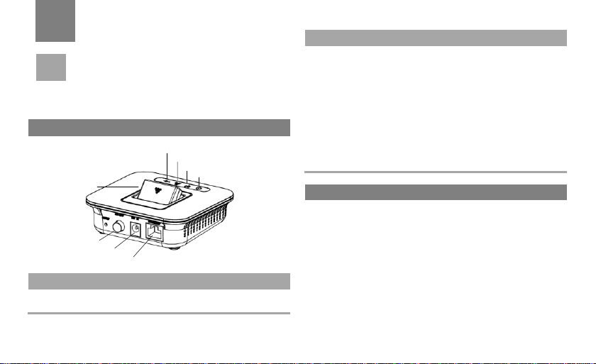
Appearance
Indicator
Status
Power
Steady on and in red: The device is switched
on successfully.
Indicator
Status
LAN
Powered device connected to the
associated port and the Ethernet interface
is ready to work.
Blinking in yellow green: Data is being
transmitted.
WLAN
Steady on and in yellow green: The WLAN
is enabled.
Blinking in yellow green: Data is being
transmitted.
USB
Steady on and in yellow green: The USB
interface is ready to work.
PC Configuration Requirements
Quick Start
1
Note
USB Interface
Power On/Off
Power Interface
Ethernet Interface
Power Indicator
WLAN Indicator
LAN Indicator
USB Indicator
The supported functions and actual appearance
are subject to your product purchased. The
following pictures are displayed for illustration
purpose only. For details of your product selection,
consult your service provider.
The recommended PC configurations for using the device
are as follows:
CPU: Pentium 500 MHz or above
Memory: 128 MB RAM or above
Hard disk: 100 MB or above available space
Operating System: Windows 2000, Windows XP,
Windows Vista or Windows 7
LCD resolution: 800*600 pixel or above, recommended
1024*768 pixel
1
Page 8
Interface: standard USB interface
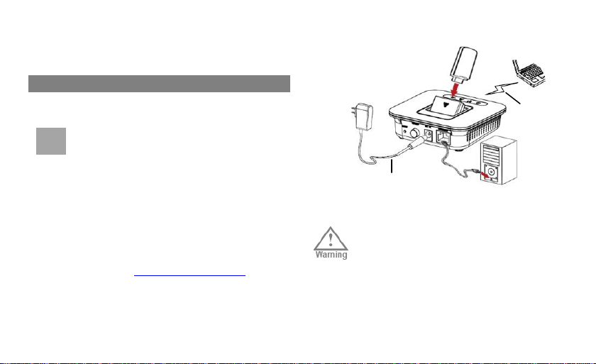
Installation
Use a power adapter that is compatible with
the device; otherwise, the device may be
damaged.
Please use the AC/DC power supply
defined in the specifications of the charger.
An improper power voltage can cause fire
or malfunction of the charger.
Note
WLAN
Power Adapter
Internet Browser: Internet Explorer 6.0 or Internet
Explorer 7.0, Firefox 1.5 or Firefox 2.0, Safari 3.0
Step 1: Connect with the data card through
the USB interface.
Use the specified data card to connect with the
device.
Step 2: Connect to a PC through an Ethernet
cable or WLAN.
If the indicator of the Ethernet interface connecting with
a network cable is on, the PC lineate connection is
successful. The Ethernet cable cannot be longer than
100 meters (328 feet). To achieve better effect, use the
shielded cable.
Whether the PC wireless connection is successful,
please check your PC connected through WLAN. For
details, please see “Configuring Your Computer”.
If connect your device to one PC with the Ethernet cable
and other PCs with WLAN simultaneously, you have
constructed a LAN and can share the local resources.
2
Step 3: Connect to the power adapter.
Page 9

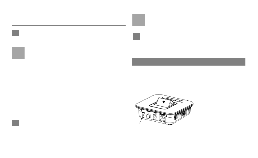
Step 4: Place the device.
To prevent electrical devices from being
interfered by wireless signals, place
electrical devices one meter away from the
device.
Do not put the data card in the slot and
please turn the USB interface connected
with the data card upright when the device
is running.
Dial-up Access
Logging In to the Management Page
1
Note
2
Note
The device can be placed horizontally or vertically on a
table. Place the device on a higher place or near the
window, so it can receive stronger signals.
Step 5: Power On/Off.
Press the Power key to switch on the device; press and
hold the Power key to switch off the device.
By default, the device dials up to access the Internet as
required. You can directly use the network services such
as web browsing, and receiving or sending emails.
Make sure that the data card is connected to the
device, or else you cannot use the Internet service
and some management pages are unavailable.
Start the Internet browser and enter the address
http://192.168.1.1 in the address bar.
Enter the Account and Password, and then click Apply.
The default value is admin.
To avoid the configuration conflict, only one user is
allowed to log in to the management page at a
time.
3
Page 10
Accessing the Internet
Click Basic Settings > Internet Settings,
Restoring the Factory Defaults
1
Note
2
Note
3
Reset
choose 3.5G Client.
If you are required to enter the PIN code, enter the
correct one. If you fail to enter the correct PIN or
PUK code, the network-related functions are
unavailable.
The SIM card is supplied by the service provider.
For details, contact your service provider.
When the Save PIN Code check box is selected,
the Auto validation is enabled.
If Auto validation is enabled, the PIN code is
recorded and automatically validated after each
restart.
If PPP Connection is Manual, click Connect/
Disconnect to connect to or disconnect from the
network.
4
If PPP Connection is Auto or On Demand, refresh
the page to view the current network connection
status.
Wait for several minutes. If you are notified that
the connection is successful, you can start the
browser and enter the website address to access
the Internet.
If you need to reconstruct the network or you forget the
changes of some parameters, you can choose to restore
factory defaults and reconfigure the device.
Reset: Press and hold
it for 2 seconds to
restore the factory
defaults.
Note: After this
operation, all
restored to the defaults.
configurations are
Page 11

Management Page Overview
Management Page Overview
Item
Description
Status
Displays the parameter configuration
status of the device.
Basic Settings
Configures the LAN/WAN interface.
Wireless
Configures the wireless settings.
Security&NAT
Configures the firewall-related settings
and other Network Address Translation
services.
Administration
Configures the administration-related
settings.
Advanced
Configures the routing and UPnP settings.
Logout
Log out of the management page.
Viewing Status Info
Overview
2
Using the Management Page
1 2 3
4
The following table shows the main operations in the
management page.
On the configuration page, you can view the current
parameter configuration information and the network
connection status.
Click Status.
Click Overview to view the device status, such
as the summary information of System, 3.5G
Status, WAN/LAN interface and wireless.
Click Active DHCP Leases to check the DHCP
clients. Click Update button to refresh the page
and update the CHCP clients, and Back button to
return to the Overview page.
Click Association List to check stations which
associated to this AP here.
5
Page 12

6
Statistics
1
2
3
Click Status.
Click Statistics to view the summary for the
device statistics, such as the memory size and
WAN/LAN traffic statistics.
Click Update button to refresh the page and reset
the statistics.
Page 13

Wireless Configuration
Configuration Requirements
Configuring the Wireless Network
3
Configuring Your Computer
1 2 3
4
5
This takes the Windows XP operating system (OS) as
an example to describe how to configure your computer.
For other OSs, the configurations may be different and
you need to configure them as required.
The wireless configuration allows your PC to connect to the
device through the wireless network. If you need only the
Ethernet to connect your PC, you can skip this part.
To set up wireless network connection, your PC must be
configured with the WLAN adapter that supports the IEEE
802.11 b/g protocol.
If the encryption function is enabled, you need to ensure
that all PCs connecting to the device use the same key as
that of the device.
For the use of WLAN adapter, refer to the WLAN adapter
user guide provided by the manufacturer.
For the encryption configurations, see "Security Setting >
Security Policy".
For SSID parameters configuration, see "Wireless
Settings > Basic Settings > Wireless Network".
Choose Start > Control Panel > Network
Connections > Wireless Network Connection.
Click Show Wireless Networks to display the
wireless network connection list.
Select the network connection that the SSID is the
same as that of the device, and then click Connect.
If the encryption parameter is set for the device, the
Wireless Network Connection dialog box is
displayed and requires the network key and
confirmation. The value you entered must be the
same as the WPA Pre-Shared Key or Network Key
of the device.
Wait for a while after you enter the correct network
key. The wireless connection icon displays in the
7
Page 14

status area in the lower right corner of the screen.
Configuring the PC Network
Configuring the Network Connection
Disabling Proxy Settings
1
2 3 4 1 2
3
Then, your PC can automatically connect to the
device.
The recommended configurations of the PC are as
follows:
Obtain an IP address automatically.
Deselect Use a proxy server for your LAN.
Choose My Network Places > Properties > Local
Area Connection.
Right-click the Local Area Connection icon and
select Properties.
In the Local Area Connection Properties dialog
box, select Internet Protocol (TCP/IP) in the This
connection uses the following items list box, and
then click Properties.
8
In the Internet Protocol (TCP/IP) Properties dialog
box, select Obtain an IP address automatically
and Obtain DNS server address automatically,
and then click OK.
Start the Internet browser, and then choose Tools >
Internet Options.
Select the Connections tab, and then click LAN
Settings.
In the LAN Settings dialog box, deselect Use a
proxy server for your LAN.
Page 15

Network Settings
IP Address Reservation
4
Basic Settings
Note
Click Basic Settings, you can configure network and
internet settings.
Click Network Settings to go to LAN Interface
configuration page; such as LAN IP and DHCP Server.
All the settings will also apply o wireless LAN interface.
IP Address: The default IP address of the device is
192.168.1.1.
Subnet Mask: The combination of the subnet mask and
IP address enables the flexible sub netting. By default,
the subnet mask is 255.255.255.0.
DHCP Server: It is used to assign IP addresses
dynamically. If the DHCP server is Enabled, it can
automatically assign IP addresses for PCs. It is
recommended to select Enabled for the DHCP server.
DHCP Lease Time: The DHCP server automatically
assigns an IP address to each device connected to the
network. When the leased time expires, the DHCP
server checks whether the device is connected to the
network. If the device is disconnected from the network,
the server assigns the IP address to another device.
Thus, the IP address is not wasted.
IP Pool Range: It is used to define the IP address range
that the host can use during the IP address assignment.
For example, in the network segment 192.168.1.0/24,
the default IP address of the device is 192.168.1.1. The
host IP address can range from 192.168.1.2 to
192.168.1.254. The minimum range is a single IP
address.
The Start IP Address must be smaller than or
equal to the End IP Address.
If the DHCP Server is Enabled, the
configurations of Start IP Address, End IP
address, and DHCP Lease Time are valid;
otherwise, you cannot configure them.
Click Edit Address Reservation to configure IP
address for specific LAN client by the MAC address.
Please input the MAC address of the LAN client PC, and
then specify the IP address that will be assigned to the client;
click Apply after checking the Enable box.
9
Page 16

Internet Settings
Click Internet Settings to go to WAN Interface
Gateway
3.5G Client
configuration page for the device mode settings.
Choose Gateway as the Device Mode and then
configure the gateway releated settings in the
corresponding fields.
DHCP Client: Set DUT to get IP address dynamically
from the local DHCP server.
Use MAC Clone: Click Clone button to use the local PC
MAC as the device MAC address.
PPPoE Client: Input the username and password
according to the local PPPoE server to be permitted to
connect to the server and get IP address dynamically
from the PPPoE server.
Connection Mode: Select the PPPoE access mode.
Keep Alive: The device automatically connects to the
Internet and does not disconnect when no data is
transmitted.
10
Connect on Demand: The device automatically connects
to the PPPoE server when data transmission exists. When
the duration of no data transmission exceeds the
maximum idle time, the device disconnects the
connection.
Manual Connect: The device connects to the PPPoE
server after you click Connect on the connection page.
Static Config: Input the connection information
according to the local server in these fields.
Choose 3.5G Cilent as the Device Mode and then
configure the PPP 3.5G client related settings in the
corresponding fields.
APN Service(APN): If the service provider provides the
relevant parameters, select Static and enter the APN
value. Otherwise, select Dynamic and the device
automatically obtains the APN value.
Username/Password Service: Select Enable and enter
the username/password value if the internet service
provider (ISP) provides the relevant parameters.
Otherwise, select Disable. The user name and
password is used to obtain the service authorization
Page 17

provided by the ISP.
Note
Service Number: Input the dial-up number which is
used to initiate the network call.
Connection Mode: Select the dial-up access mode.
Keep Alive: The device automatically connects to the
Internet and does not disconnect when no data is
transmitted.
Connect on Demand: The device automatically connects
to the Internet when data transmission exists. When the
duration of no data transmission exceeds the maximum
idle time, the device disconnects the Internet connection.
Manual Connect: The device connects to the Internet
after you click Connect on the connection page. For details,
see "Accessing the Internet".
PIN Code Service: Click PIN Code Config button to go
to the configuration page.
PIN Code Operation: Select Disable/Modify to disable or
modify the PIN Code. Please input the new PIN Code and
then confirm the PIN Code in the corresponding field if
Modify is selected.
PIN Code: Input the effective PIN code to validate the
configuration of the PIN Code.
New PIN Code/ Reconfirm new PIN Code: Input the new
PIN code and input it again for confirmation.
Please be noted that the maximum number of
times of PIN input will be 3, so PUK code will be
needed to unlock the PIN code input.
11
Page 18

Basic Settings
Wireless Network
Mode
Description
11b only
The device can only work in the low
performance 802.11b standard network
mode.
Mode
Description
11g only
The device can only work in the low
performance 802.11g standard network
mode.
11b/g mixed
mode
The device can work in 802.11b/g
standard network mode at the same time.
11b/g/n mixed
mode
The device can work in 802.11b/g/n
standard network mode at the same time.
5
Wireless Settings
Click Wireless, you can configure wireless-related
settings.
Click Basic Settings to configrue the basic wireless
settings, such as Network Name (SSID) and Channel,
etc., You also can disable/enable wireless function in
this page.
Enabling or Disabling the WLAN (Radio On/Off)
Click RADIO OFF to disable the wireless service; or RADIO
ON to enable it.
Configuring the 802.11 Mode (Network Mode)
12
Network Name (SSID)
Entering a name (SSID) for your WLAN.
The service set identifier (SSID) is used to identify a WLAN. A
PC and the wireless device can perform normal data
communication only when they have the same SSIDs. To
ensure the WLAN security, do not use the default SSID. You
can enter a character string as the SSID, such as MyHome.
Broadcast SSID
Enabling or Disabling the SSID Broadcast.
Enabled: The device broadcasts the SSID of the WLAN and
users can easily access the WLAN. In this case,
unauthorized users can also try to access the WLAN because
the SSID is broadcasted.
Page 19

Disabled: The device does not broadcast the SSID of the
WDS
Note Note
WLAN. Before accessing the WLAN, a user must obtain the
SSID of the WLAN. In this case, the WLAN security is
improved.
For the convenience of users accessing the
WLAN, you can select Enabled for SSID
Broadcast when you configure the WLAN
setting. After the setting, you can select
Disabled to improve the WLAN security.
Selecting a WLAN Channel
Channel: It refers to the channel that the device works with. If
you do not know which channel to select, select Auto Select
and the device can automatically search for the channel.
WDS Mode
Disable: Disable all WDS function.
Lazy Mode: Turn on WDS function; DUT will learn
automatically from WDS packet.
Bridge Mode: Turn on WDS function, the peer WDS APs are
listed in the "AP MAC Address" field below. In this mode, AP
will not send beacon out and will not deal with probe request
packets, therefore STA will not be possible to connect with it.
Repeater Mode: Turn on WDS function, the peer WDS APs
are listed in the "AP MAC Address" field below.
Phy Mode
CCK: Modulation method used for 802.11b, g, n mode.
OFDM: Modulation method used for 802.11g, 802.11b/g
mixed mode.
HTMIX: Modulation method used for 802.11b/g/n mixed
mode.
GREENFIELD: Modulation method used for 802.11/n mode.
Encryption Mode
None: Encryption service is disabled.
WEP: Please configure the WEP encryption key in the
Wireless > Security Setting section.
TKIP: Input the WPA encryption key.
AES: Input the WPA encryption key.
In the WEP mode, devices should keep the
same security settings to make the WDS work.
In the TKIP/AES mode, the key in the WDS key
field should keep the same value to make the
WDS work.
13
Page 20

HT Physical Mode
Security Settings
Security Policy
This service is only available for 802.11b/g/n mixed
mode.
Operation Mode
Mixed Mode: Downward compatible for 802.11b/g mode.
Green Field: Only works for 802.11n mode.
Channel Bandwidth
20: Only the availble channel can be used.
20/40: More channels can be selected for use if the
bandwidth reaches 40.
Extension Channel
Only availabe if 20/40 is selected in the Channel Bandwidth
option.
Select from the drop-down list the other channel for use if the
bandwidth the device monitors is 40.
14
Click Security Settings to set up the wireless security
and encryption to prevent from unauthorized access and
monitoring.
To access the WLAN, you must set the wireless security
key on your PC to be the same as that of the wireless
device. A security key can protect your WLAN from
illegal data attacking. The security key of your wireless
device must be consistent with that of the PC.
Disabled
The wireless security service is disabled.
OPEN
Open system authentication. A user accessing the WLAN
can only use WEP as the Encryption Type.
Page 21

SHARED
Access Policy
Policy
Description
Disable
The MAC address filter function is
disabled.
Allow
The clients with addresses in the MAC
Addresses list are allowed to connect
with the device through the WLAN.
Reject
The clients with addresses in the MAC
Addresses list are not allowed to
connect with the device through the
WLAN.
Shared key authentication. It can only use WEP. The user
accessing the WLAN must use the WEP to authenticate.
WEP
Wireless Equivalent Privacy (WEP) is a 64-bit or 128-bit data
encryption method. The 128-bit WEP encryption provides
higher security level.
WEP Key 1~4 : You can enter 5 ASCII characters or
10-character hexadecimal numeral to form a 64-bit key. You
can also enter 13 ASCII characters or 26-character
hexadecimal numeral to form a 128-bit key.
Default Key: Select from the drop-down list the WEP key
which will be in use.
WPA-PSK/WPA2-PSK
WPA-PSK: It is a 256-bit data encryption method that can
automatically change the key.
WPA2-PSK: It is a more secure version of WPA-PSK and it
supports the IEEE 802.11i standard.
WPA Algorithm: TKIP, AES, TKIP+AES.
WPA Pre-Shared Key (Pass Phrase): You can enter a
64-character hexadecimal value or 8-63-character ASCII
value as the key. The ASCII value contains all characters that
can be entered through the PC keyboard, and the
hexadecimal value contains numbers of 0-9 and characters
of A-F. For example, you can enter the ASCII value of
1234abcde as the key.
Key Renewal Interval: It is used to set how long a network
key is dynamically changed. By default, it is 3600.
Also known as WLAN MAC Filter function. You can
control and manage the clients accessing the WLAN,
and improve the WLAN security performance.
Policy
The following table shows the Policy type:
15
Page 22

Add a station MAC
Advanced Settings
Enter MAC addresses in the list. The device can perform the
access control over the clients whose MAC addresses are in
the list.
Click Advanced Settings to make detailed settings for
the Wireless. Advanced Setup includes items that are
not available from the Basic Settings page, such as
Beacon Interval, Control Tx Rates and Basic Data
Rates.
BG Protection Mode
Default value is Auto. You can select the other options
including On and Off. The BG protection technology is
CTS-To-Self. It will try to reserve the throughput for 11g
clients from 11b clients connecting to the device as AP mode.
Beacon Interval
Beacons are the packets sending by Access point to
synchronize the wireless network. The beacon interval is the
time interval between beacons sending by this unit in AP or
AP+WDS mode. The default and recommended beacon
interval is 100 milliseconds.
16
Data Beacon Rate (DTIM)
This is the Delivery Traffic Indication Map. It is used to alert
the clients that multicast and broadcast packets buffered at
the AP will be transmitted immediately after the transmission
of this beacon frame. You can change the value from 1 to 255.
The AP will check the buffered data according to this value.
For example, selecting “1” means to check the buffered
data at every beacon.
Fragment Threshold
The fragmentation threshold determines the size at which
packets are fragmented (sent as several pieces instead of as
one block). Use a low setting in areas where communication
is poor or where there is a great deal of radio interference.
This function will help you to improve the network
performance.
RTS Threshold
The RTS threshold determines the packet size at which the
radio issues a request to send (RTS) before sending the
packet. A low RTS Threshold setting can be useful in areas
where many client devices are associating with the device, or
in areas where the clients are far apart and can detect only
the device and not each other. You can enter a setting
ranging from 0 to 2347 bytes.
TX Power
The default TX power is 100%. In case of shortening the
Page 23

distance and the coverage of the wireless network, input a
smaller value to reduce the radio transmission power. For
example, input 80 to apply 80% Tx power.
Country Code
y It is used to identify the country or district. Different countries
or districts have different standards on channel usage.
Choose None to make maximum number of channel
available for use
y Channel selection must be limited for devices marketed in the
US/Canada to channel 1 ~ 11.
y Country code selection feature must be disabled (firmware)
for devices marketed to the US/Canada
Station List
Click Station List to monitor stations which associated
to this AP.
17
Page 24

Firewall Settings
MAC/IP/Port Filtering
Port Forwarding
6
Security & NAT
1
1 2 3
Click Security & NAT to configure firewall and
NAT-releated settings.
Click Firewall Settings to configure firewall related
functions.
SPI Firewall
By default, SPI Firewall is Enabled. Choose Disable and
click Apply to disable the firewall function; but please be
noted that the firewall protection will be lost, and any packet
inspections and filtering features won’t take effect.
Ping from WAN Filter
By default, it is Enabled. Choose Disable and click Apply to
enable the ping from WAN.
Click MAC/IP/Port Filtering to set up filtering fules for
protection against virus, worm and malicious activity on
the Internet.
18
Choose Always to activate the configuration of
filtering services. The default value is Never and no
filering rules can be added in this page.
Enter the following values as required:
Source MAC Address: To specify the MAC address from
which to deny data transmission.
Destination/Source IP Address: To specify IP address to
deny data transmission.
Protocol: Here provides three default policies for security
levels for you to choose.
Dest/Source Port Range: The port range is from 0 to 65535.
Please key in the start point and end point for the Filtering.
Click Apply to create the filtering rule; or Cancel to give
up the previous settings; or Delete Selected after
selecting specific entry to delete the filtering rule.
Click Port Forwarding to configure the virtual serve to
Page 25

enable external computers to access WWW, FTP, or
DMZ
2
3 4 1 1 2
3
other services provided by the LAN.
Choose Enable from the drop-down to activate the
configuration of the virtual server. This value is
Disable by default.
Select from the pre-defined services list for the
virtual server. Otherwise please select the Protocol
the user-defined services will use; and then input the
start/end port value in the Port Range field.
Input the Internal IP Address of the LAN client PC
that wil provide the virtual server service.
Click Add to create the virtual server; or Cancel to
give up the previous settings; or Delete Selected
after selecting specific entry to delete the virtual
server.
Click DMZ to configure DMZ IP address.
If your PC cannot run network applications through the
device, you can set the computer to access the Internet
unlimitedly by configuring the IP address of the
computer in the demilitarized zone (DMZ).
However, the DMZ computer is not protected by the
firewall. It is vulnerable to attack and may also put other
computers in the home network at risk.
Select Enable/Disable for DMZ Status to enable or
disable the DMZ service.
Enter the local IP address of the computer that is
specified as a DMZ host.
Click Apply button to confirm the setting; or Cancel
to give up the previous settings.
19
Page 26

Management
Administrator Settings
Remote Management
Log
7
Administration
1 2 3 1 2 3 1
2
3
Click Administration to configure administration-related
functions for the device.
Click Management to configure adminstration settings,
such as Account modification and Remote Access
Management.
Select Enable/Disable to enable or disable the
HTTP Remote Access service.
Keep the default value or enter the Remote Port if
the service is enabled.
Click Apply to save the configuration; or Cancel to
give up the previous settings.
Modify the Account name and Password if
necessary.
Enter the new password again in the Re-enter
Password field.
Click Apply to save the configuration; or Cancel to
give up the previous settings.
20
Click Log to configure system log inforamtion service.
Select Enable/Disable to enable or disable the
system log information service.
Click Apply to save the configuration.
If Log service is enabled, you can click Refresh
button to update the log information; or Clear button
to clear the log information; or Save button to save
Page 27

the log information to the local PC; or Debug button
System
Firmware Upgrade
Restore Factory Defaults
Reboot System
System Language
1
2 31
2
1
2
to save the debug information to the local PC.
Click System to configure system configuration services,
such as firmware upgrade, restore factory default and
reboot system.
Click Browse button to locate the new firmware for
upgrade.
Click Upgrade button to start the process.
Please wait until the upgrade completes and log in
again.
Click Factory Defaults button to restore the device
to default values.
Please wait until the process completes and log in
again.
Click Reboot button to start the process.
Please wait until the process completes and log in
again.
Choose from the drop-down list the language for the
GUI page.
21
Page 28

Advanced Routing
UPnP
8
Advance
1 2 1
2
Click Advance to configue Advanced Routing and
UPnP function.
Click Advanced Routing to configure routing table. A
Static IP Routing is a manually defined path, which
determines the data transmitting route. If your local
network is composed of multiple subnets, you may want
to specify a routing path to the routing table.
Enter the following values as required:
Destination: Display the IP address that the data packets are
to be sent.
Host/Net: Choose Host to specify the host IP in the
Destination field that the data packets are to be sent;
otherwise choose Net to specify network IP in the Destination
field that the data packets are to be sent and then also input
the Subnet Mask value.
Subnet Mask: Input the value in this field if Net is chosen in
22
the Host/Net field.
Gateway: Specify the gateway information that the
transmitting data will pass through.
Interface: Specify the interface information that the
transmitting data will pass through.
Click Apply to confirm to add the static routing; or
Cancel to give up the previous settings; or Delete
Selected after selecting specific entry to delete the
static routing.
The Universal Plug and Play (UPnP) service allows
other network users to control your device’s network
features to realize the intelligent interconnection.
Select Enabled/Disabled for UPnP Status to enable
or disable the UPnP service.
Click Apply.
Page 29

9
Troubleshooting
1
2
3
4
5
6
7 8 9 1 2
What to do if a PC in the LAN cannot access the
Internet?
If the Power indicator is off, you need to check whether
the power adapter is normally connected
If the USB indicator if off, you need to check whether the
data card is connected normally.
If the signal strength indicator in the page is off, you need
to check whether the area is covered by the network.
If the area is covered by the network, you need to check
the indicator of the Ethernet interface.
If the indicator of the Ethernet interface blinks, the
corresponding Ethernet interface is normally connected.
If the indicator is off, you need to check and ensure that
the related Ethernet connection is normal.
You must configure the correct PPP user name and PPP
password when you access the Internet through the
device. Check whether they are correct, and see "3.5G
Client " for details.
If the DHCP service is disabled and the PC obtains the
IP address dynamically, the PC also cannot access the
Internet. You can change the mode to manually assign
an IP address. See "Configuring the Network
Connection".
Check whether the driver of the network adapter is
correctly installed.
If the preceding methods cannot solve the problem,
please consult your service provider.
What to do if a PC in the WLAN cannot access
the WLAN?
If interferences or shields near the device exist, you can
adjust the position of the device. When the signal
strength is strong, you can move to the next step.
Check and record the following data on the network
adapter of your PC: SSID, Encryption type, and key.
23
Page 30

Check and record the following data on the device: SSID,
3 4 1 2 1 2 3 4 5 6 7
8
Encryption type, and key.
Compare the recorded data, the SSID on the network
adapter should be ANY or be the same as that on the
device. The WEP type and key on the network adapter
and device should be the same. Otherwise, you need to
change the data on the network adapter.
What to do if bridging between two devices is
unsuccessful?
Make sure that the two devices work on the same
channel. For details, see "Selecting a WLAN Channel".
Make sure that the MAC address of one device is in the
peer MAC address list of the other device. For details,
see "WDS".
When the signal strength is normal, what to do if
the downloading rate is low?
In this case, you need to set the value in the registry as
24
follows:
Choose Start > Run.
Enter regedit in the Open text box and then click OK.
Select parameters in the following directory:
\HKEY_LOCAL_MACHINE\SYSTEM\CurrentControlS
et\Services\Tcpip.
Choose Edit > New > DWORD Value.
Rename New Value #1 to TcpWindowSize.
Right-click TcpWindowSize and then select Modify.
Select Decimal and enter 65535 in the Value data text
box, and then click OK.
For the DWORD Value of DefaultRcvWindow, do the
same operations as that of TcpWindowSize.
Page 31

3G
The Third Generation
AP
Access Point
APN
Access Point Name
CDMA
Code Division Mutiple Access
DHCP
Dynamic Host Configuration Protocol
DNS
Domain Name Server
EDGE
Enhanced Data rates for GSM
Evolution
GSM
Global System for Mobile
communications
GPRS
General Packet Radio Service
HSPA
High Speed Packet Access
HSDPA
High Speed Downlink Packet Access
IP
Internet Protocol
LAN
Local Area Network
LED
Light Emitting Diode
NAT
Network Address Translation
POTS
Plain Old Telephone Service
VoIP
Voice over IP
UMTS
Universal Mobile
Telecommunications System
10
Abbreviations
25
Page 32

Electronic Device
11
Warnings and Precautions
Turn off your device near high-precision electronic devices.
The wireless device may affect the performance of these
devices.
Such devices include hearing aids, pacemakers, fire alarm
systems, automatic gates, and other automatic-control
devices can be affected. If you are using an electronic
medical device, consult the device manufacturer to confirm
whether the radio wave affects the operation of this device.
Notice
The information in this manual is subject to change
without notice. Every effort has been made in the
preparation of this manual to ensure accuracy of the
contents, but all statements, information, and
recommendations in this manual do not constitute the
warranty of any kind, expressed or implied.
CE statements:
Please observe the national local regulations in the
location where product is to be used. This product may
be restricted for use in some or all countries of
European Union.
Warning: This is a radio frequency device! The
26
spectrum usage is regulated on a country base, by the
spectrum authorities. National restrictions may apply!
Please read the user manual carefully and check the
local regulation before importing this product to any
particular country.
Warning: When carrying or using the wireless device,
keep the antenna at least 25 centimeters away from
your body, to avoid negative impact on your health
caused by radio frequency leakage.
Warning: Do not go closer that 20 cm to the device
while in operation.
Warning: this product is restricted to indoor use only!
The User must observe local regulations before putting
the WLAN Adaptor into use.
Hereby, Huawei Technologies Co., Ltd., declares that
this product is in compliance with the essential
requirements and other relevant provisions of Directive
1999/5/EC.
The declaration of conformity may be consulted at
www.huaweidevice.com/certification.
Page 33

Federal Communications Commission (FCC)
Hospital
Statement
This device complies with Part 15 of the FCC Rules,
Operation is subject to the following two conditions:
this device may not cause harmful interference, and
this device must accept any interference received,
including interference that may cause undesired
operation.
Changes or modifications made to this equipment not
expressly approved by Huawei Technologies Co., Ltd.
may void the FCC authorization to operate this
equipment.
This equipment has been tested and found to comply with
the limits for a Class B digital device, pursuant to Part 15 of
the FCC Rules. These limits are designed to provide
reasonable protection against harmful interference in a
residential installation. This equipment generates, uses and
can radiate radio frequency energy and, if not installed and
used in accordance with the instructions, may cause harmful
interference to radio communications. However, there is no
guarantee that interference will not occur in a particular
installation. If this equipment does cause harmful
interference to radio or television reception, which can be
determined by turning the equipment off and on, the user is
encouraged to try to correct the interference by one or more
of the following measures:
Reorient or relocate the receiving antenna.
Increase the separation between the equipment and
receiver.
Connect the equipment into an outlet on a circuit different
from that to which the receiver is connected.
Consult the dealer or an experienced radio/TV technician
for help.
RF Exposure Information
This device meets the government’s requirements for
exposure to radio waves.
This device is designed and manufactured not to exceed the
emission limits for exposure to radio frequency (RF) energy
set by the Federal Communications Commission of the U.S.
Government.
This device complies with FCC radiation exposure limits set
forth for an uncontrolled environment. In order to avoid the
possibility of exceeding the FCC radio frequency exposure
limits, human proximity to the antenna shall not be less than
20cm (8 inches) during normal operation.
Pay attention to the following points in hospitals or health
care facilities:
Do not take your wireless device into the operating room
(OR), intensive care unit (ICU), or coronary care unit
27
Page 34

(CCU).
Traffic Safety
Storage Environment
Children Safety
Do not use your wireless device at places for medical
treatment where wireless device use is prohibited.
Please observe local laws and regulations on wireless
device use. Do not use your wireless device while driving
to avoid traffic accident.
Secure the wireless device on its holder. Do not place the
wireless device on the seat or other places where it can
get loose in a sudden stop or collision.
Use the wireless device after the vehicle stops at a safe
place.
Do not place the wireless device over the air bag or in the
air bag outspread area. Otherwise, the wireless device
may hurt you owing to the strong force when the air bag
inflates.
Observe the rules and regulations of airline companies.
When boarding or approaching a plane, turn off the
wireless device. In areas where wireless device use is
prohibited, turn off the wireless device. Otherwise, the
radio signal of the wireless device may disturb the plane
control signals. Turn off your wireless device before
boarding an aircraft.
28
Do not place magnetic storage media such as magnetic
cards and floppy disks near the wireless device.
Radiation from the wireless device may erase the
information stored on them.
Do not put your wireless device, and other accessories in
containers with strong magnetic field, such as an
induction cooker and a microwave oven. Otherwise,
circuit failure, fire, or explosion may occur.
Do not leave your wireless device, and other accessories
in a very hot or cold place. Otherwise, malfunction of the
products, fire, or explosion may occur.
Do not place sharp metal objects such as pins near the
earpiece. The earpiece may attract these objects and hurt
you when you are using the wireless device.
Do not subject your wireless device, and other
accessories to serious collision or shock. Otherwise,
wireless device malfunction, overheat, fire, or explosion
may occur.
Do not put your wireless device in the back pocket of your
trousers or skirt to avoid wireless device damage while
seated.
Put your wireless device, and other accessories in places
beyond the reach of children. Do not allow children to use
the wireless device, or other accessories without
guidance.
Page 35

Do not allow children to touch the small fittings. Otherwise,
Operation Environment
Cleaning and Maintenance
suffocation or gullet jam can be caused if children
swallow the small fittings.
The wireless device, and other accessories are not
water-resistant. Keep them dry. Protect the wireless
device, or other accessories from water or vapor. Do not
touch the wireless device with a wet hand. Otherwise,
short-circuit and malfunction of the product or electric
shock may occur.
Do not use the wireless device in dusty, damp and dirty
places or places with magnetic field. Otherwise,
malfunction of the circuit may occur.
When carrying or using the wireless device, keep the
wireless device at least 20 centimeters away from your
body, to avoid negative impact on your health caused by
radio frequency leakage.
On a thunder stormy day, do not use your wireless device
outdoors or when it is being charged.
The wireless device may interfere with nearby TV sets,
radios and PCs.
In accordance with international standards for radio
frequency and radiation, use wireless device accessories
approved by the manufacturer only.
The antenna(s) used for this transmitter must be installed
to provide a separation distance of at least 20cm from all
persons.
Before you clean or maintain the wireless device, turn off
it and disconnect it from the power adapter. Otherwise,
electric shock or short-circuit may occur.
Do not use any chemical detergent, powder, or other
chemical agent (such as alcohol and benzene) to clean
the wireless device and the other accessories. Otherwise,
part damage or a fire can be caused. You can clean the
wireless device and the other accessories with a piece of
soft antistatic cloth that is a little wet.
Do not scratch the shell of the wireless device. Otherwise,
the shed coating may cause skin allergy. Once it happens,
stop using the wireless device at once and go to see a
doctor.
If the wireless device or any of its fittings does not work,
turn to the local authorize service center for help.
29
 Loading...