

Page 1

HP ZBook 17 G2 Mobile Workstation
Maintenance and Service Guide
Page 2

© Copyright 2014 Hewlett-Packard
Development Company, L.P.
Bluetooth is a trademark owned by its
proprietor and used by Hewlett-Packard
Company under license. Intel and Core are
trademarks or registered trademarks of Intel
Corporation in the United States and other
countries. Microsoft and Windows are U.S.
registered trademarks of Microsoft
Corporation. SD Logo is a trademark of its
proprietor.
The information contained herein is subject to
change without notice. The only warranties for
HP products and services are set forth in the
express warranty statements accompanying
such products and services. Nothing herein
should be construed as constituting an
additional warranty. HP shall not be liable for
technical or editorial errors or omissions
contained herein.
First Edition: September 2014
Document Part number: 774963-001
Product notice
This guide describes features that are common
to most models. Some features may not be
available on your computer.
Not all features are available in all editions of
Windows 8. Your computer may require
upgraded and/or separately purchased
hardware, drivers, and/or software to take full
advantage of Windows 8 functionality. See
http://www.microsoft.com for details.
Page 3

Important Notice about Customer Self-Repair Parts
CAUTION: The computer includes Customer Self-Repair parts and parts that should only be accessed by an
authorized service provider. See Chapter 5, "Removal and replacement procedures for Customer Self-Repair
parts," for details. Accessing parts described in Chapter 6, "Removal and replacement procedures for
Authorized Service Provider only parts," can damage the computer or void the computer warranty.
iii
Page 4

iv Important Notice about Customer Self-Repair Parts
Page 5

Safety warning notice
WARNING! To reduce the possibility of heat-related injuries or of overheating the computer, do not place
the computer directly on your lap or obstruct the computer air vents. Use the computer only on a hard, flat
surface. Do not allow another hard surface, such as an adjoining optional printer, or a soft surface, such as
pillows or rugs or clothing, to block airflow. Also, do not allow the AC adapter to contact the skin or a soft
surface, such as pillows or rugs or clothing, during operation. The computer and the AC adapter comply with
the user-accessible surface temperature limits defined by the International Standard for Safety of
Information Technology Equipment (IEC 60950).
v
Page 6

vi Safety warning notice
Page 7

Table of contents
1 Product description ....................................................................................................................................... 1
2 External component identification ................................................................................................................. 7
Display ................................................................................................................................................................... 7
Buttons and speakers ............................................................................................................................................ 8
Keys ...................................................................................................................................................................... 10
Lights ................................................................................................................................................................... 11
TouchPad ............................................................................................................................................................. 12
Front ..................................................................................................................................................................... 13
Left ....................................................................................................................................................................... 14
Right ..................................................................................................................................................................... 15
Rear ...................................................................................................................................................................... 16
Bottom ................................................................................................................................................................. 17
3 Illustrated parts catalog .............................................................................................................................. 19
Service tag ........................................................................................................................................................... 19
PCID label ............................................................................................................................................................. 20
Windows 8 models ............................................................................................................................ 20
Non-Windows 8 models .................................................................................................................... 21
Computer major components ............................................................................................................................. 22
Display assembly components ........................................................................................................................... 27
Bracket Kit ........................................................................................................................................................... 29
Cable Kit ............................................................................................................................................................... 30
Plastics Kit ........................................................................................................................................................... 31
Mass storage devices .......................................................................................................................................... 32
Miscellaneous parts ............................................................................................................................................. 33
Sequential part number listing ........................................................................................................................... 34
4 Removal and replacement procedures preliminary requirements .................................................................... 41
Tools required ...................................................................................................................................................... 41
Service considerations ........................................................................................................................................ 41
Plastic parts ....................................................................................................................................... 41
Cables and and pointing stick connectors ........................................................................................ 41
Drive handling ................................................................................................................................... 42
Grounding guidelines ........................................................................................................................................... 42
Electrostatic discharge damage ....................................................................................................... 42
vii
Page 8

Packaging and transporting guidelines ......................................................................... 43
Workstation guidelines ................................................................................................... 43
Equipment guidelines ..................................................................................................... 44
5 Removal and replacement procedures for Customer Self-Repair parts ............................................................. 45
Component replacement procedures ................................................................................................................. 45
Battery ............................................................................................................................................... 45
SIM card ............................................................................................................................................. 46
Service cover ..................................................................................................................................... 47
Hard drives, primary and secondary ................................................................................................. 48
Solid-state drive ................................................................................................................................ 50
WLAN module .................................................................................................................................... 51
WWAN module ................................................................................................................................... 53
RTC battery ........................................................................................................................................ 55
Optical drive ...................................................................................................................................... 56
Upgrade Bay hard drive ..................................................................................................................... 58
Expansion memory module .............................................................................................................. 60
Keyboard ........................................................................................................................................... 61
Primary memory module .................................................................................................................. 64
6 Removal and replacement procedures for Authorized Service Provider parts ................................................... 66
Component replacement procedures ................................................................................................................. 66
Display bezel ..................................................................................................................................... 66
Display panel ..................................................................................................................................... 68
Webcam/microphone module .......................................................................................................... 70
Top cover ........................................................................................................................................... 71
Multifunction board ........................................................................................................................... 75
Speakers ............................................................................................................................................ 77
Fingerprint reader ............................................................................................................................. 78
Power button board .......................................................................................................................... 79
Display assembly .............................................................................................................................. 81
ExpressCard assembly ...................................................................................................................... 87
Smart Card reader ............................................................................................................................. 88
Audio/USB board ............................................................................................................................... 89
Processor heat sink ........................................................................................................................... 91
Processor ........................................................................................................................................... 94
Graphics subsystem heat sink .......................................................................................................... 96
Graphics board .................................................................................................................................. 99
Power connector cable ................................................................................................................... 101
System board .................................................................................................................................. 102
viii
Page 9

7 Computer Setup (BIOS), MultiBoot, and System Diagnostics in Windows 8 ...................................................... 106
Using Computer Setup ....................................................................................................................................... 106
Starting Computer Setup ................................................................................................................ 106
Navigating and selecting in Computer Setup ................................................................................. 106
Restoring default settings in Computer Setup ............................................................................... 107
Updating the BIOS ........................................................................................................................... 107
Determining the BIOS version ...................................................................................... 107
Downloading a BIOS update ......................................................................................... 109
Using MultiBoot ................................................................................................................................................. 109
About the boot device order ........................................................................................................... 109
Choosing MultiBoot preferences .................................................................................................... 110
Setting a new boot order in Computer Setup .............................................................. 110
Dynamically choosing a boot device using the f9 prompt ........................................... 110
Setting a MultiBoot Express prompt ............................................................................ 111
Entering MultiBoot Express preferences ..................................................................... 111
Using System Diagnostics ................................................................................................................................. 111
8 Computer Setup (BIOS), MultiBoot, and UEFI in Windows 7 ............................................................................ 113
Using Computer Setup ....................................................................................................................................... 113
Starting Computer Setup ................................................................................................................ 113
Navigating and selecting in Computer Setup ................................................................................. 113
Restoring default settings in Computer Setup ............................................................................... 114
Updating the BIOS ........................................................................................................................... 114
Determining the BIOS version ...................................................................................... 115
Downloading a BIOS update ......................................................................................... 115
Using MultiBoot ................................................................................................................................................. 117
About the boot device order ........................................................................................................... 117
Choosing MultiBoot preferences .................................................................................................... 117
Setting a new boot order in Computer Setup .............................................................. 117
Dynamically choosing a boot device using the f9 prompt ........................................... 118
Setting a MultiBoot Express prompt ............................................................................ 118
Entering MultiBoot Express preferences ..................................................................... 118
Using HP PC Hardware Diagnostics (UEFI) (select models only) ...................................................................... 118
Downloading HP PC Hardware Diagnostics (UEFI) to a USB device ............................................... 119
9 Computer Setup (BIOS) and Advanced System Diagnostics in SUSE Linux ........................................................ 120
Starting Computer Setup .................................................................................................................................. 120
Using Computer Setup ....................................................................................................................................... 120
Navigating and selecting in Computer Setup ................................................................................. 120
Restoring default settings in Computer Setup ............................................................................... 122
ix
Page 10

Updating the BIOS .............................................................................................................................................. 122
Determining the BIOS version ......................................................................................................... 122
Downloading a BIOS update ........................................................................................................... 123
Using Advanced System Diagnostics ................................................................................................................ 123
10 Specifications .......................................................................................................................................... 125
Computer specifications .................................................................................................................................... 125
11 Backup and recovery in Windows 8 ............................................................................................................ 126
Backing up your information ............................................................................................................................. 126
Performing a system recovery .......................................................................................................................... 127
Using f11 recovery tools ................................................................................................................. 127
Using Windows 8 operating system media (purchased separately) ............................................. 128
Using Windows Refresh for quick and easy recovery .................................................................... 129
Remove everything and reinstall Windows .................................................................................... 129
Using HP Software Setup ................................................................................................................ 130
12 Backup and recovery in Windows 7 ............................................................................................................ 131
Creating recovery media and backups .............................................................................................................. 131
Guidelines ........................................................................................................................................ 131
Creating recovery media with HP Recovery Disc Creator ............................................................... 131
Creating recovery media .............................................................................................. 132
Backing up your information .......................................................................................................... 132
Performing a system recovery .......................................................................................................................... 133
Using the Windows recovery tools ................................................................................................. 133
Using f11 recovery tools (select models only) ............................................................................... 135
Using Windows 7 operating system media .................................................................................... 135
13 Backup and Recovery in SUSE Linux ........................................................................................................... 137
Creating backups ............................................................................................................................................... 137
Creating restore media ...................................................................................................................................... 137
Backing up your information ............................................................................................................................. 137
Performing a system recovery .......................................................................................................................... 138
Remove everything and reinstall SLED ............................................................................................................. 139
14 Statement of memory volatility ................................................................................................................ 140
Nonvolatile memory usage ............................................................................................................................... 141
Questions and answers ..................................................................................................................................... 143
Using HP Sure Start (select models only) ......................................................................................................... 145
x
Page 11

15 Power cord set requirements .................................................................................................................... 146
Requirements for all countries ......................................................................................................................... 146
Requirements for specific countries and regions ............................................................................................. 146
16 Recycling ................................................................................................................................................ 148
Index ........................................................................................................................................................... 149
xi
Page 12

xii
Page 13

1 Product description
Category Description
Product Name HP ZBook 17 G2 Mobile Workstation
Processors
●
Intel® Core™ i7-4940MX 3.10-GHz (SC turbo up to 4.00-GHz) processor (1600-MHz FSB, 8.0-MB L3
cache, quad core, 8 threads, 57-W)
●
Intel Core i7-4910MQ 2.90-GHz (SC turbo up to 3.90-GHz) processor (1600-MHz FSB, 8.0-MB L3
cache, quad core, 8 threads, 47-W)
●
Intel Core i7-4810MQ 2.80-GHz (SC turbo up to 3.80-GHz) processor (1600-MHz FSB, 6.0-MB L3
cache, quad core, 8 threads, 47-W)
●
Intel Core i7-4710MQ 2.50-GHz (SC turbo up to 3.50-GHz) processor (1600-MHz FSB, 6.0-MB L3
cache, quad core, 8 threads, 47-W)
●
Intel Core i7-4610M 3.00-GHz (SC turbo up to 3.70-GHz) processor (1600-MHz FSB, 4.0-MB L3 cache,
dual core, 4 threads, 37-W)
●
Intel Core i5-4340M 2.90-GHz (SC turbo up to 3.60-GHz) processor (1600-MHz FSB, 3.0-MB L3 cache,
dual core, 4 threads, 37-W)
●
Intel Core i5-4210M 2.60-GHz (SC turbo up to 3.20-GHz) processor (1600-MHz FSB, 3.0-MB L3 cache,
dual core, 4 threads, 37-W)
Chipset Mobile Intel QM87 chipset
Graphics Support for the following graphics subsystem boards (all feature OpenGL driver support, hybrid
(switchable) graphics, DisplayPort 1.2, up to 4 total displays (through APR), and NVIDIA Mosaic
Technology):
●
NVIDIA Quadro K610M, N15E-Q2, 1 GB dedicated GDDR5 video memory
●
NVIDIA Quadro K3100M, N15E-Q1, 4 GB dedicated GDDR5 video memory
●
NVIDIA Quadro K4100M, N15E-Q3, 4 GB dedicated GDDR5 video memory
●
NVIDIA Quadro K5100M, N15E-Q5, 8 GB dedicated GDDR5 video memory
Display All displays are 16:9 aspect ratio, 7.2-mm, wedge design, low-voltage differential signalling (LVDS) panels
●
17.3-in, high definition plus (HD+), 1600×900, Anti-Glare (AG), light-emitting diode (LED), SVA, with
or without webcam
●
17.3-in, full high definition (FHD), 1920×1080, AG, LED, WVA, with or without webcam
Memory 4 customer-accessible/upgradable memory module slots
Supports dual-channel memory
Supports up to 32,768 MB of system RAM
DDR3L 1600-MHz PC3-12800 SODIMMs
Supports the following configurations:
●
2048 MB total system memory (2048 × 1)
●
4096 MB total system memory (2048 × 2)
●
4096 MB total system memory (4096 × 1)
Memory (continued) Supports the following configurations:
1
Page 14

Category Description
●
8192 MB total system memory (8192 × 1)
●
8192 MB total system memory (4096 × 2)
●
12288 MB total system memory (8192 + 4096)
●
16384 MB total system memory (8192 x 2)
●
16384 MB total system memory (4096 x 4); only available on computer models equipped with a
quad-core processor
●
32768 MB total system memory (8192 x 4); only available on computer models equipped with a
quad-core processor
Flash cache 32 GB MLC mSATA module
Support for “No flash cache” option
Dedicated mini-card slot
Intel SRT (Smart Response Technology)
Not available with SSD or SED drives
Not available with Linux
Fast Flash Standby not supported
Not available if primary and secondary and Upgrade bay hard drive is selected
Mini card SSD 128 GB
Primary storage Supports 7.0 mm (0.28 in) or 9.5 mm (0.37 in), 6.35 cm (2.5 in) hard drives and 6.35 cm (2.5 in) solid-state
drive for primary and secondary storage.
Supports 3D DriveGuard
Supports toolless remove mechanism
Supports the following Serial ATA (SATA) drives:
●
1-TB, 7200-RPM, SATA, 9.5-mm
●
1-TB, 5400-RPM, SATA, 7.0-mm
●
750-GB, 7200-RPM, SATA, 7.0-mm
●
500-GB, 7200-RPM, SATA, 7.0-mm
●
500-GB, 7200-RPM, self-encrypting drive (SED), 7.0-mm
●
500-GB, 5400-RPM, SATA, FIPS, 7.0-mm
Supports the following 6.35 cm (2.5 in), solid-state drives (SSD):
●
512 GB, SATA-3
●
256 GB, SATA-3, SED, Opal2
●
256 GB, SATA-3, SED, Opal1
●
256 GB, SATA-3
●
240 GB, SATA-3
●
180 GB, SATA-3
●
128 GB, SATA-3
Secondary storage Supports 7.0 mm (0.28 in) or 9.5 mm (0.37 in), 6.35 cm (2.5 in) hard drives and 6.35 cm (2.5 in) solid-state
drive for primary and secondary storage.
2 Chapter 1 Product description
Page 15

Category Description
Supports the following SATA drives:
●
1-TB, 7200-RPM, SATA, 9.5-mm
●
1-TB, 5400-RPM, SATA, 7.0-mm
●
750-GB, 7200-RPM, SATA, 7.0-mm
●
500-GB, 7200-RPM, SATA, 7.0-mm
●
500-GB, 7200-RPM, SED, 7.0-mm
●
500-GB, 5400-RPM, SATA, FIPS, 7.0-mm
Supports the following 6.35 cm (2.5 in), solid-state drives (SSD):
●
512 GB, SATA-3
●
256 GB, SATA-3, SED, Opal2
●
256 GB, SATA-3, SED, Opal1
●
256 GB, SATA-3
●
240 GB, SATA-3
●
180 GB, SATA-3
●
128 GB, SATA-3
Upgrade bay Support for RAID 0/1/5
Supports 7.0 mm (0.28 in) or 9.5 mm (0.37 in) hard drives:
●
750 GB, 5400 rpm
●
512 GB SATA III SSD
●
256 GB SATA III SSD, SED
Supports the following 9.5 mm (0.37 in) SATA optical drives:
●
Blu-ray R/RE DVD±RW SuperMulti Double-Layer Drive
●
Blu-ray ROM DVD±RW SuperMulti Double-Layer Drive
●
DVD±RW SuperMulti Double-Layer Drive
Supports no drive option
Audio and video Integrated dual-array microphone
High-definition (HD) audio with DTS Studio Sound
2 stereo speakers
Integrated 720p HD webcam
Supports no camera option
Ethernet Intel I217-LM Gigabit Network Connection
Power optimizer support
Intel Stable Image Platform Program (SIPP)
Ethernet cable not included
Wireless Integrated wireless local area network (WLAN) options by way of the following wireless modules:
●
WLAN Intel Dual Band Wireless-AC 7260 802.11 ac 2×2 WiFi + Bluetooth 4.0 Combo Adapter
3
Page 16

Category Description
●
WLAN Intel Dual Band Wireless-N 7260AN 802.11 a/b/g/n 2×2 WiFi + Bluetooth 4.0 Combo Adapter
●
WLAN Intel Dual Band Wireless-N 7260AN 802.11 a/b/g/n 2×2 WiFi + Bluetooth 4.0 Combo Adapter
●
WLAN Intel Dual Band Wireless-N 7260NB 802.11 a/b/g/n 2×2 WiFi adapter
WLAN antennas (2) built into display assembly
Support for no WLAN option
Integrated wireless wide area network (WWAN) options by way of the following wireless modules: (not
available on computer models with Dream Color displays)
●
HP hs3110 HSPA+ Mobile Broadband Module
●
HP lt4111 LTE/EV-DO/HSPA+ Mobile Broadband Module
●
HP lt4112 LTE/HSPA+ Mobile Broadband Module
Support for no WWAN option
Security provided by subscriber identify module (SIM) card
External media card One ExpressCard slot, 54 mm
Integrated SD UHS-II flash media slot
Supports next generation SD (Secure Digital). Backward compatible with SDHC, SDXC.
Ports Multi-pin AC port
Combo mic-in/Stereo headphone jack
DisplayPort 1.2
Mini DisplayPort with pass through DP 1.2 support
Docking connector
Secondary battery connector
RJ-45 (Ethernet, includes link and activity lights)
USB 3.0 (3)
USB 2.0 (1)
USB 3.0 charging port (1)
VGA (Dsub 15-pin) supporting 1920 × 1200 external resolution at 75 GHz (hot plug/unplug with autodetect)
Docking Supports the following docking stations:
●
HP Docking Station
●
HP Advanced Docking Station
Keyboard/pointing
devices
Full sized, backlit or non-backlit, chiclet (island-style) keyboard with separate numeric keypad:
Spill-resistant with drain
Keyboard/pointing
devices (continued)
Dura Keys
Touchpad includes DuraPad coating; glass with chemical etched surface; image sensor
Gestures enabled by default - 2 finger scrolling, 2 finger zoom (pinch)
4 Chapter 1 Product description
Page 17

Category Description
Touchpad supports two-way scroll with legend
Taps enabled as default
Power requirements Supports the following AC adapters with localized cable plug support:
●
230W HP Smart AC adapter
●
200W HP Smart AC adapter
●
3-wire plug (with ground pin)
Support for the following batteries:
●
8-cell, 2.80-AHr, 83-WHr, Li-ion battery
●
8-cell, 2.80-AHr, 75-WHr, Li-ion battery
Security Integrated fingerprint reader
Integrated Smart Card reader
Preboot authentication (password, Smart Card)
Supports security lock
Trusted platform module (TPM) v.1.2 and TPM enhanced drive lock
Operating system Preinstalled operating systems:
●
Windows 8 Professional 64
●
Windows 8 Professional 64 Product Key (DPK) with Windows 7 Professional 64 image (not supported
in the People’s Republic of China)
●
Windows 8 Emerging Markets (EM) 64
●
Windows 8 Multi-language (ML) 64
●
Windows 8 China (CH) 64 (only supported in the People’s Republic of China)
●
Windows 7 Professional 64
●
FreeDOS 2.0
●
Novell™: SuSE Linux™ – SLED 11, 64-bit, SP2 (not available in models with WWAN or Blu ray drives)
Restore media:
DRDVD:
●
DRDVD Windows 7
●
DRDVD Windows 8
●
SRDVD SuSE Linux Enterprise (SLED) SP2 64-bit
OSDVD:
●
Windows 7 Professional 64-bit
●
Windows 8 Professional 64-bit
Operating system
(continued)
Restore media:
OSDVD:
●
Windows 8 64-bit
●
Windows 8 Country Specific 64-bit
●
Windows 8 Emerging Market 64-bit
5
Page 18

Category Description
Certified:
●
Microsoft WHQL
●
SuSE Linux Enterprise (SLED) SP2 64-bit
Web-only support:
●
Windows 8 Enterprise 64
●
Windows 8.1 Professional 64
●
Windows 8.1 Enterprise 64
●
Windows 8.1 Emerging Markets 64
●
Windows 8.1 Chinese Markets 64
●
Win 8.1 Professional 32
●
Win 8.1 Professional 64
●
Windows 7 Professional 32
●
Windows 7 Ultimate 64
●
Windows 7 Ultimate 32
●
Windows 7 Enterprise 64
●
Windows 7 Enterprise 32
●
SuSE Linux Enterprise (SLED) SP2 64-bit
Serviceability End-user replaceable parts:
●
Memory module
●
Optical drive
●
Hard drive/SSD
●
Battery
●
AC adapter
●
Keyboard
●
WLAN module
●
WWAN module
●
mSATA
6 Chapter 1 Product description
Page 19
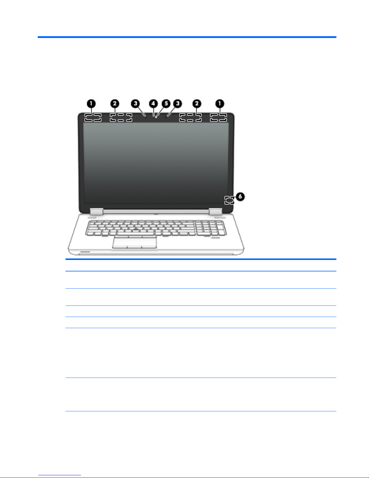
2 External component identification
Display
Component Description
(1) WLAN antennas (2)* (select models only) Send and receive wireless signals to communicate with wireless
local area networks (WLAN).
(2) WWAN antennas (2)* (select Windows
models only)
Send and receive wireless signals to communicate with wireless
wide area networks (WWAN).
(3) Internal microphones (2) Record sound.
(4) Webcam light (select models only) On: The webcam is in use.
(5) Webcam (select models only) Records video and captures still photographs.
For information on using the webcam in Windows 8, access HP
Support Assistant. To access HP Support Assistant on the Start
screen, select the HP Support Assistant app.
For information on using the webcam in Windows 7, select Start >
All Programs > Communication and Chat > HP WebCam.
(6) Internal display switch Turns off the display or initiates Sleep (Windows)/Suspend (Linux) if
the display is closed while the power is on.
NOTE: The display switch is not visible on the outside of the
computer.
*The antennas are not visible on the outside of the computer. For optimal transmission, keep the areas immediately around the
antennas free from obstructions. To see wireless regulatory notices, see the section of the Regulatory, Safety, and Environmental
Display 7
Page 20
Component Description
Notices that applies to your country or region. To access the user guides, select the HP Support Assistant app on the Start screen,
select My computer, and then select User guides.
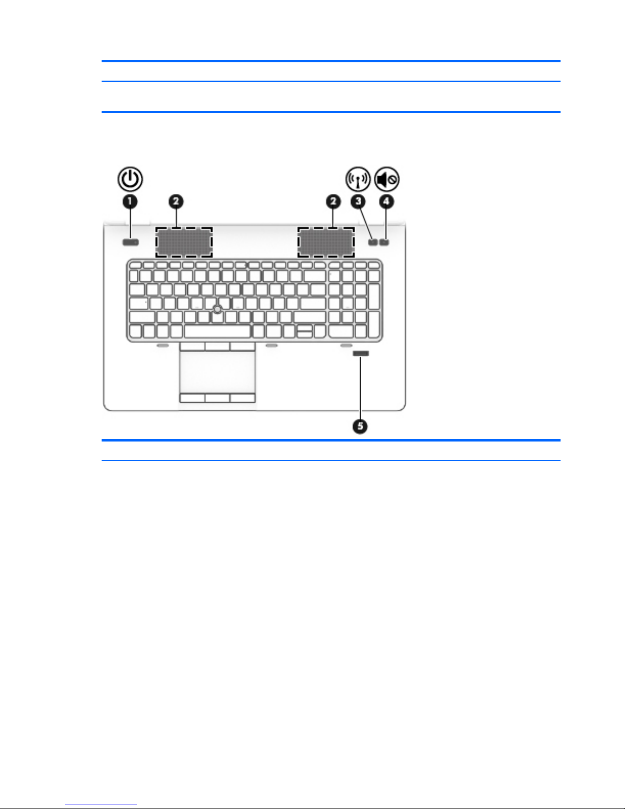
Buttons and speakers
Component Description
(1) Power button
●
When the computer is off, press the button to turn on the
computer.
●
When the computer is on, press the button briefly to initiate
Sleep (Windows)/Suspend (Linux).
●
When the computer is in the Sleep state, press the button
briefly to exit Sleep (Windows)/Suspend (Linux).
●
When the computer is in Hibernation, press the button briefly
to exit Hibernation.
CAUTION: Pressing and holding down the power button will result
in the loss of unsaved information.
If the computer has stopped responding and operating system
shutdown procedures are ineffective, press and hold the power
button for at least 5 seconds to turn off the computer.
To learn more about your power settings:
Windows 8:
See your power options. From the Start screen, type power, select
Settings, and then select Power Options
Windows 7:
8 Chapter 2 External component identification
Page 21

Component Description
See your power options. Select Start > Control Panel > System and
Settings > Power Options.
Linux:
1. Select Computer > Control Center.
2. In the left pane, click System, and then click Power
Management in the right pane.
(2) Speakers (2) Produce sound.
(3) Wireless button Turns the wireless feature on or off but does not establish a
wireless connection.
(4) Volume mute button Mutes and restores speaker sound.
(5) Fingerprint reader Allows a fingerprint logon to the operating system, instead of a
password logon.
Buttons and speakers 9
Page 22
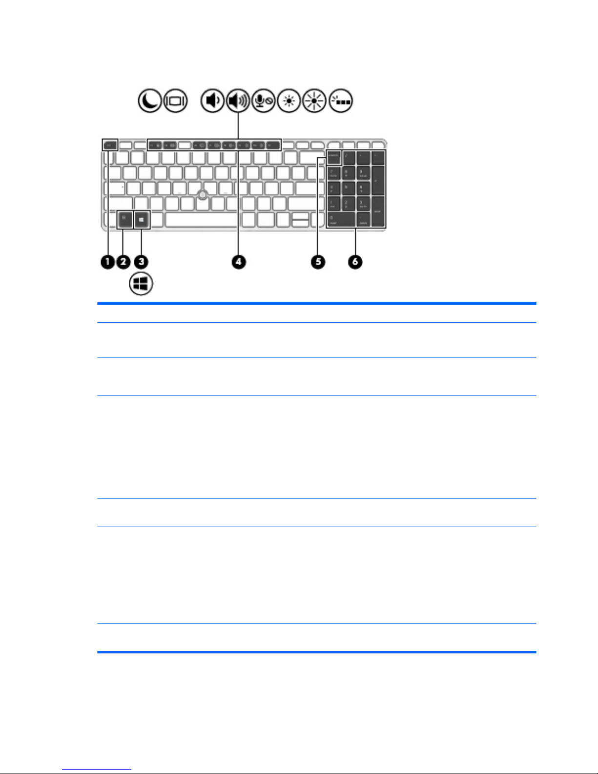
Keys
Component Description
(1) esc key
NOTE: Windows models only.
Displays system information when pressed in combination with the
fn key.
(2) fn key Executes frequently used system functions when pressed in
combination with a function key, the num lk key, the esc key, or the
b key.
(3) Windows button
NOTE: Windows models only.
Windows 8:
Returns you to the Start screen from an open app or the Windows
desktop.
NOTE: Pressing the Windows button again will return you to the
previous screen.
Windows 7:
Displays the Windows Start menu.
(4) Function keys Execute frequently used system functions when pressed in
combination with the fn key.
(5) num lk key Windows 8:
Turns the embedded numeric keypad on and off when pressed in
combination with the fn key. Alternates between the navigational
and numeric functions on the integrated numeric keypad.
Windows 7 and Linux:
Alternates between the navigational and numeric functions on the
integrated numeric keypad.
(6) Integrated numeric keypad When num lk has been enabled, it can be used like an external
numeric keypad.
10 Chapter 2 External component identification
Page 23
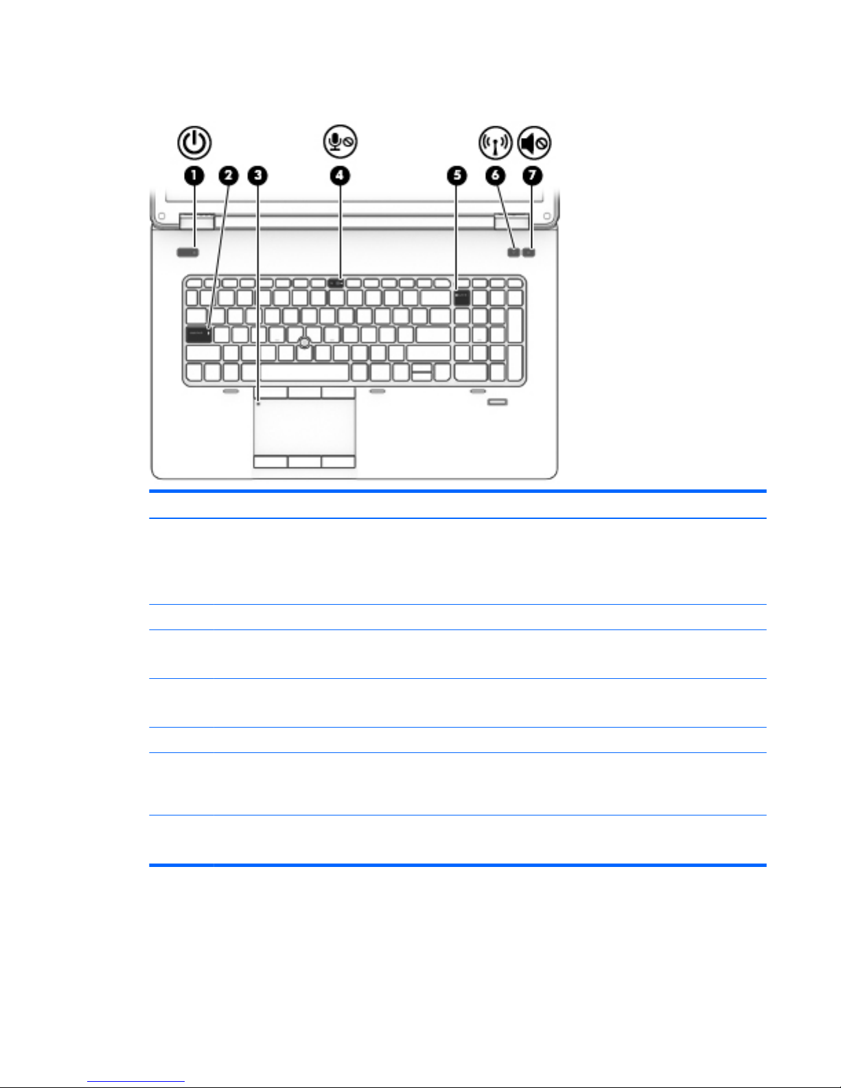
Lights
Component Description
(1) Power light
●
On: The computer is on.
●
Blinking: The computer is in the Sleep state (Windows) or
Suspend state (Linux).
●
Off: The computer is off.
(2) Caps lock light On: Caps lock is on.
(3) TouchPad light
●
Amber: The TouchPad is off.
●
Off: The TouchPad is on.
(4) Microphone mute light
●
Amber: microphone sound is off.
●
Off: microphone sound is on.
(5) Num lock light On: Num lock is on.
(6) Wireless light
●
White: An integrated wireless device, such as a wireless local
area network (WLAN) device and/or a Bluetooth® device, is on.
●
Amber: All wireless devices are off.
(7) Mute light
●
Amber: Computer sound is off.
●
Off: Computer sound is on.
Lights 11
Page 24
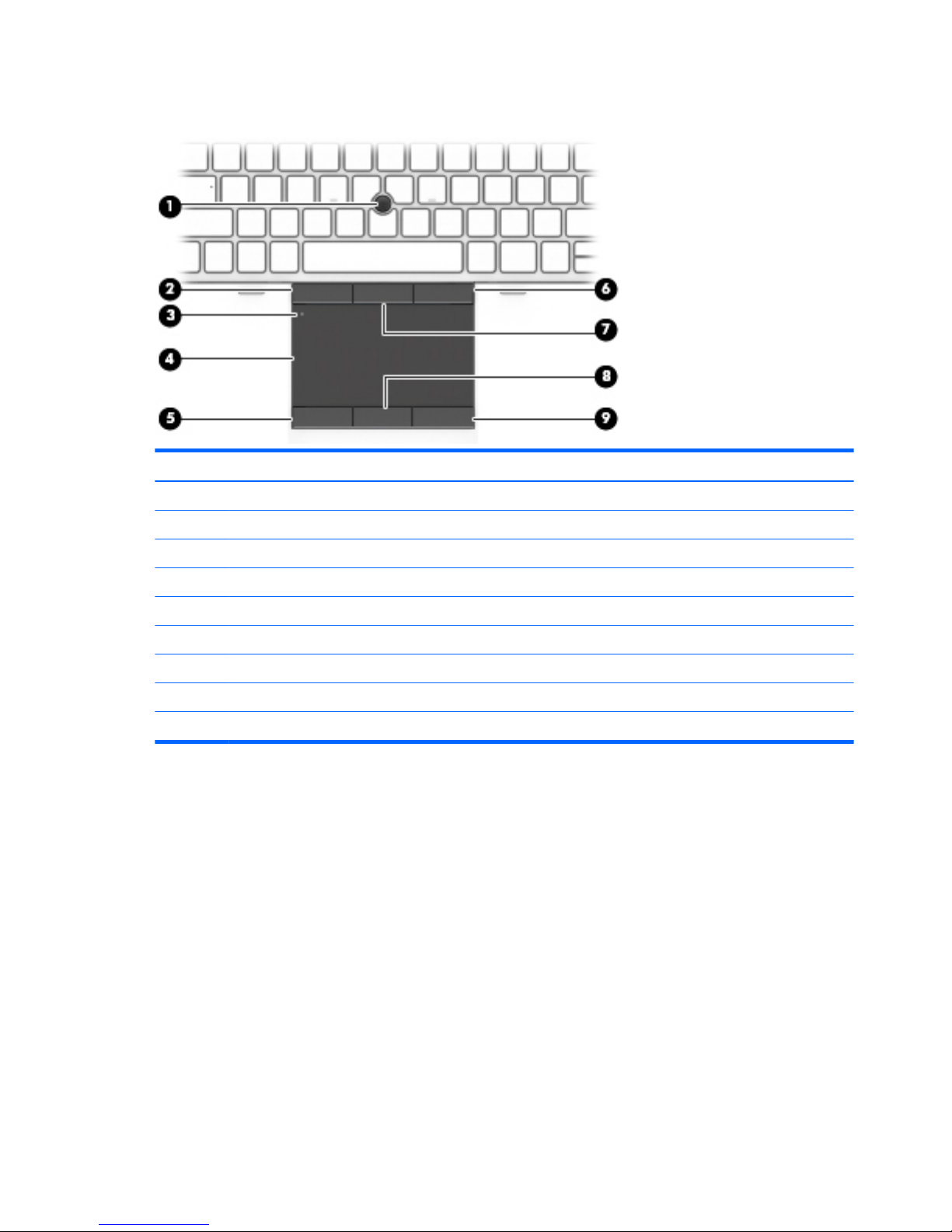
TouchPad
Component Description
(1) Pointing stick Moves the pointer and selects or activates items on the screen.
(2) Left pointing stick button Functions like the left button on an external mouse.
(3) Touchpad on/off button Turns the Touchpad on and off.
(4) Touchpad zone Moves the pointer and selects or activates items on the screen.
(5) Left TouchPad button Functions like the left button on an external mouse.
(6) Right pointing stick button Functions like the right button on an external mouse.
(7) Center pointing stick button Functions like the center button on an external mouse.
(8) Center TouchPad button Functions like the center button on an external mouse
(9) Right TouchPad button Functions like the right button on an external mouse.
12 Chapter 2 External component identification
Page 25
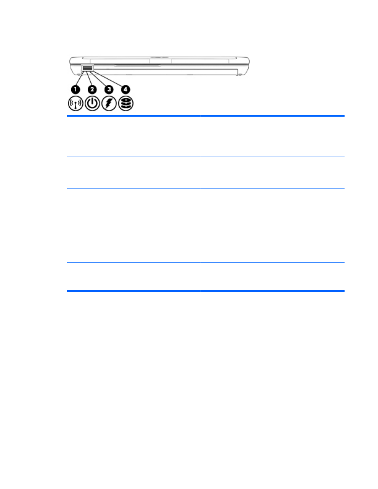
Front
Component Description
(1) Wireless light
●
White: An integrated device, such as a wireless local area
network (WLAN) device and/or a Bluetooth device, is on.
●
Amber: All wireless devices are off.
(2) Power light
●
On: The computer is on.
●
Blinking: The computer is in the Sleep state.
●
Off: The computer is off.
(3) AC adapter/Battery light
●
White: The computer is connected to external power and the
battery is charged from 90 to 99 percent.
●
Amber: The computer is connected to external power and the
battery is charged from 0 to 90 percent.
●
Blinking amber: A battery that is the only available power
source has reached a low battery level. When the battery
reaches a critical battery level, the battery light begins blinking
rapidly.
●
Off: The battery is fully charged.
(4) Hard drive light
●
Blinking white: The hard drive is being accessed.
●
Amber: HP 3D DriveGuard has temporarily parked the hard
drive.
Front 13
Page 26
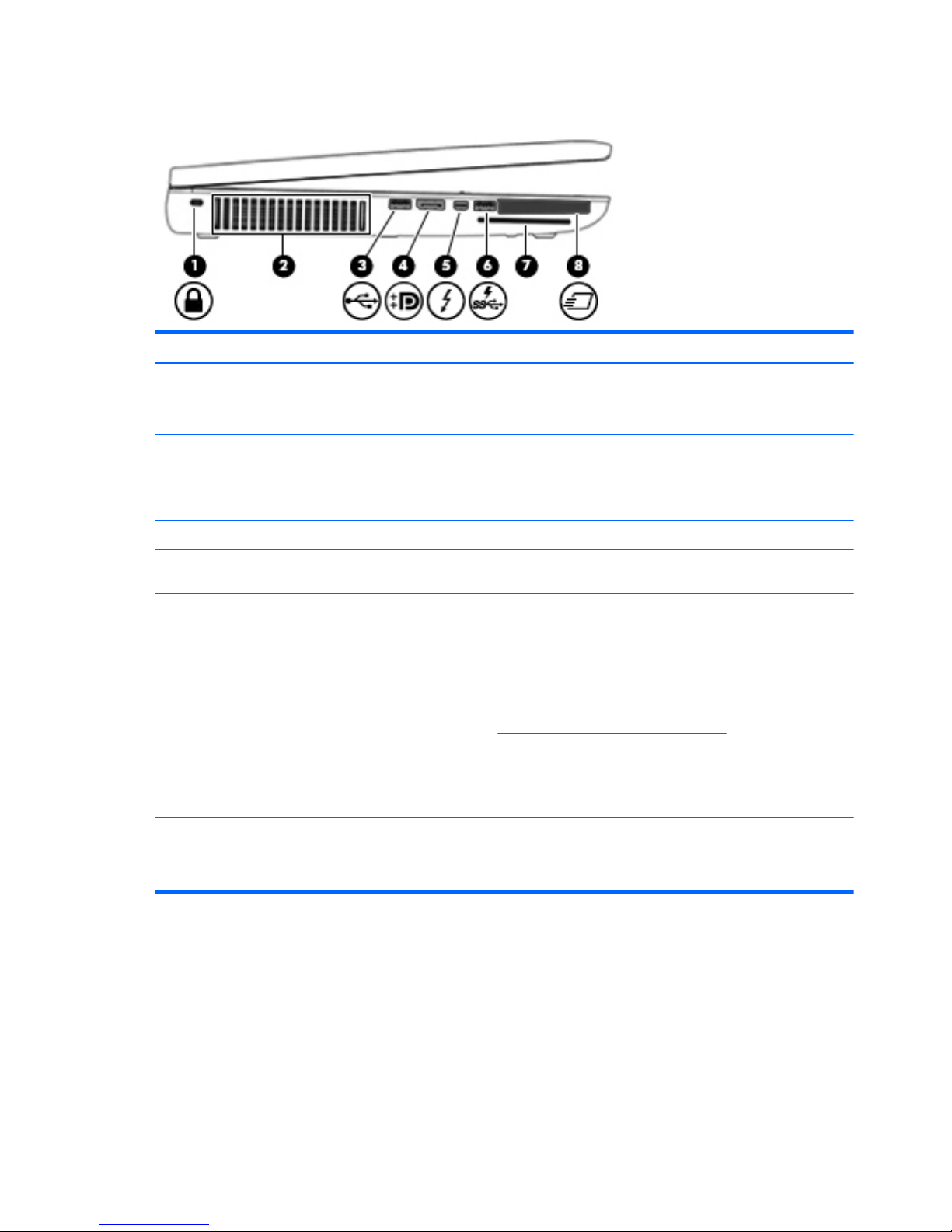
Left
Component Description
(1) Security cable slot Attaches an optional security cable to the computer.
NOTE: The security cable is designed to act as a deterrent, but it
may not prevent the computer from being mishandled or stolen.
(2) Vent Enables airflow to cool internal components.
NOTE: The computer fan starts up automatically to cool internal
components and prevent overheating. It is normal for the internal
fan to cycle on and off during routine operation.
(3) USB 2.0 port Connects an optional USB device.
(4) DisplayPort Connects an optional digital display device, such as a high-
performance monitor or projector.
(5) Thunderbolt port
NOTE: Windows models only.
Connects an optional high-resolution display device or a highperformance data device.
NOTE: Thunderbolt is new technology. Install all the latest drivers
for your Thunderbolt device before connecting the device to the
Thunderbolt port. Thunderbolt cable and Thunderbolt device (sold
separately) must be compatible with Windows. To determine
whether your device is Thunderbolt Certified for Windows, see
https://thunderbolttechnology.net/products.
(6) USB 3.0 charging port Connects optional USB 3.0 devices and provides enhanced USB
power performance. The USB charging port can also charge select
models of cell phones and MP3 players, even when the computer is
off.
(7) Smart card Support optional smart cards.
(8) ExpressCard slot or smart card reader
(depending on the configuration)
Supports optional ExpressCards or smart cards.
14 Chapter 2 External component identification
Page 27
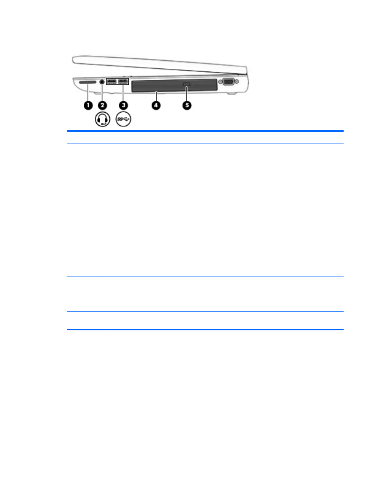
Right
Component Description
(1) Memory card reader Reads data from and writes data to memory cards such as Secure
Digital (SD).
(2) Audio-out (headphone) jack/Audio-in
(microphone) jack
Produces sound when connected to optional powered stereo
speakers, headphones, earbuds, a headset, or television audio. Also
connects an optional headset microphone.
WARNING! To reduce the risk of personal injury, adjust the volume
before putting on headphones, earbuds, or a headset. For additional
safety information, see the Regulatory, Safety, and Environmental
Notices. To access the user guides in Windows 8, select the HP
Support Assistant app on the Start screen, select My computer, and
then select User guides. To access the user guides in Windows 7,
select the HP Support Assistant app on the Start screen, select My
computer, and then select User guides.
NOTE: When a device is connected to the jack, the computer
speakers are disabled.
NOTE: Be sure that the device cable has a 4-conductor connector
that supports both audio-out (headphone) and audio-in
(microphone).
(3) USB 3.0 ports (2) Connect optional USB 3.0 devices and provide enhanced USB power
performance.
(4) Optical drive (select models only) Reads and/or writes, depending on your computer model, to an
optical disc.
(5) Optical drive eject button (select models
only)
Releases the optical drive disc tray.
Right 15
Page 28

Rear
Component Description
(1) RJ-45 (network) jack Connects a network cable.
(2) Vents (2) Enable airflow to cool internal components.
NOTE: The computer fan starts up automatically to cool internal
components and prevent overheating. It is normal for the internal
fan to cycle on and off during routine operation.
(3) Power connector Connects an AC adapter.
(4) AC adapter
●
White: The computer is connected to external power.
●
Off: The computer is not connected to external power.
16 Chapter 2 External component identification
Page 29
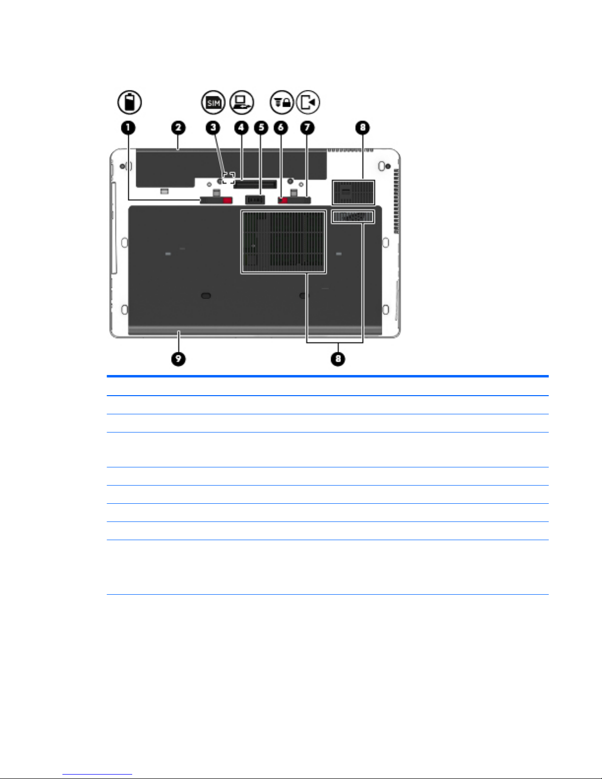
Bottom
Component Description
(1) Battery release latch Releases the battery.
(2) Battery bay Holds the battery.
(3) SIM slot
NOTE: Select Windows models only.
Supports a wireless subscriber identity module (SIM). The SIM slot is
located inside the battery bay.
(4) Docking connector Connects an optional docking device.
(5) Accessory battery connector Connects an optional accessory battery.
(6) Service door release lock Locks service door.
(7) Service door release latch Releases the service door on the computer.
(8) Vents (3) Enable airflow to cool internal components.
NOTE: The computer fan starts up automatically to cool internal
components and prevent overheating. It is normal for the internal
fan to cycle on and off during routine operation.
(9) Service door Provides access to the hard drive bay, the wireless LAN (WLAN)
module slot, the WWAN module slot, and the memory module slots.
Bottom 17
Page 30

Component Description
CAUTION: To prevent an unresponsive system, replace the
wireless module only with a wireless module authorized for use in
the computer by the governmental agency that regulates wireless
devices in your country or region. If you replace the module and then
receive a warning message, remove the module to restore computer
functionality, and then contact support through HP Support
Assistant. To access HP Support Assistant in Windows 8, on the Start
screen, select the HP Support Assistant app. To access Help and
Support in Windows 7, select Start > Help and Support.
18 Chapter 2 External component identification
Page 31
3 Illustrated parts catalog
NOTE: HP continually improves and changes product parts. For complete and current information on
supported parts for your computer, go to http://partsurfer.hp.com, select your country or region, and then
follow the on-screen instructions.
Service tag
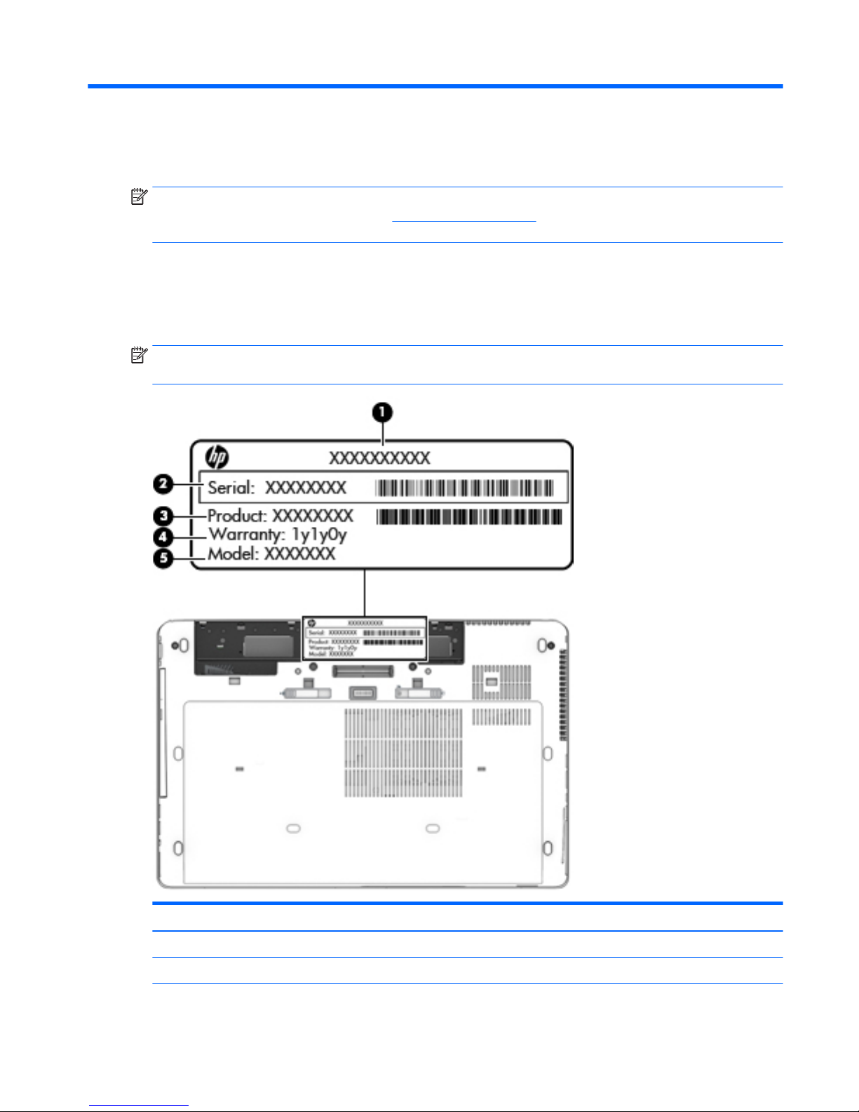
When ordering parts or requesting information, provide the computer serial number and model number
provided on the service tag.
NOTE: The computer service labels will resemble one of the examples shown in this section. Refer to the
illustration that most closely matches the service label on the computer.
Item Component Description
(1) Product name This is the product name affixed to the front of the computer.
(2) Serial number (s/n) This is an alphanumeric identifier that is unique to each product.
Service tag 19
Page 32
Item Component Description
(3) Product number (p/n) This number provides specific information about the product’s
hardware components. The part number helps a service technician
determine what components and parts are needed.
(4) Warranty period This number describes the duration of the warranty period for the
computer.
(5) Model number (select models only) This is the alphanumeric identifier needed to locate documents,
drivers, and support for the computer.
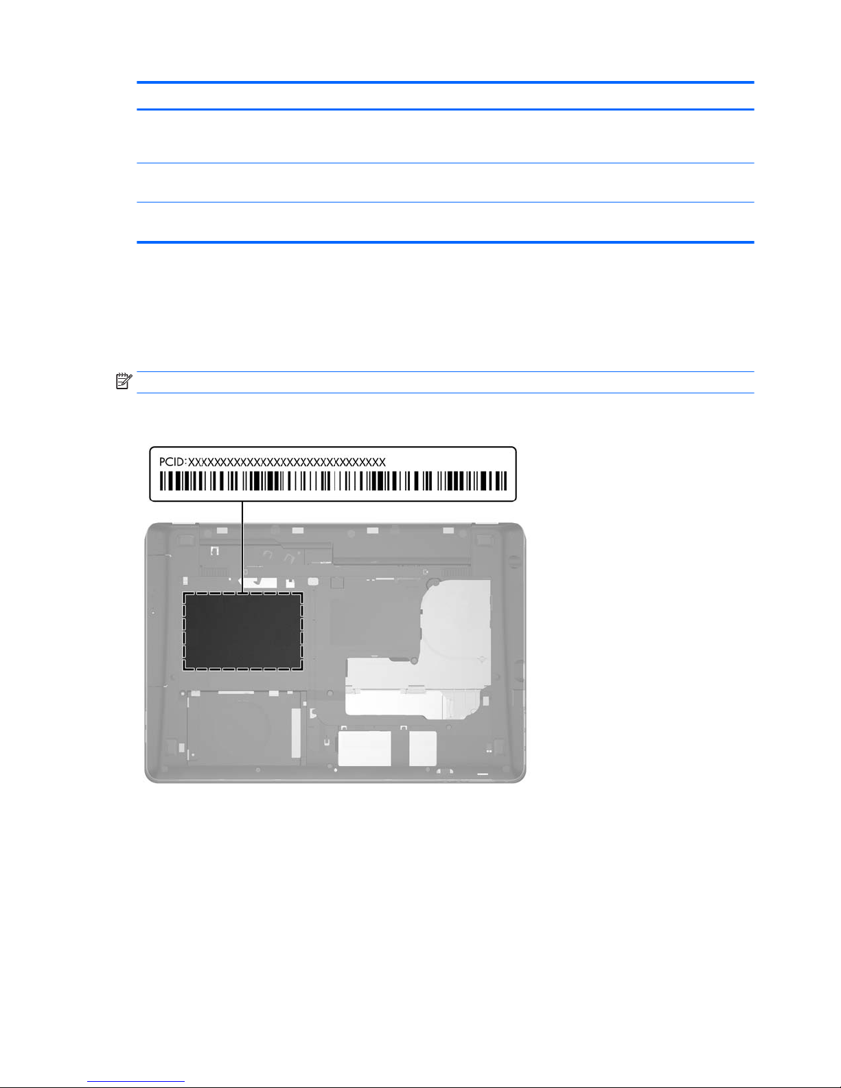
PCID label
The PCID label provides the information required to properly reset the notebook firmware (BIOS) back to
factory shipped specifications when replacing the system board. The label may have a different number of
characters depending on the operating system on the computer.
NOTE: Computer details may vary from images.
Windows 8 models
20 Chapter 3 Illustrated parts catalog
Page 33
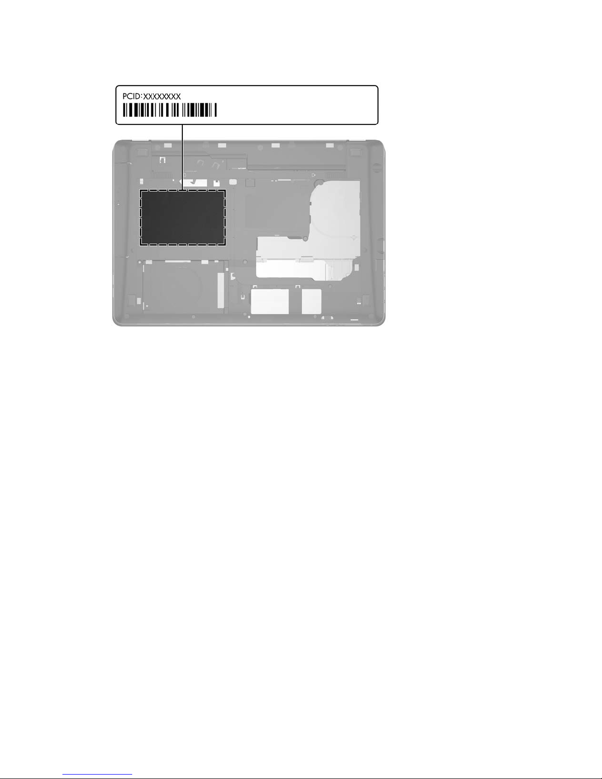
Non-Windows 8 models
PCID label 21
Page 34
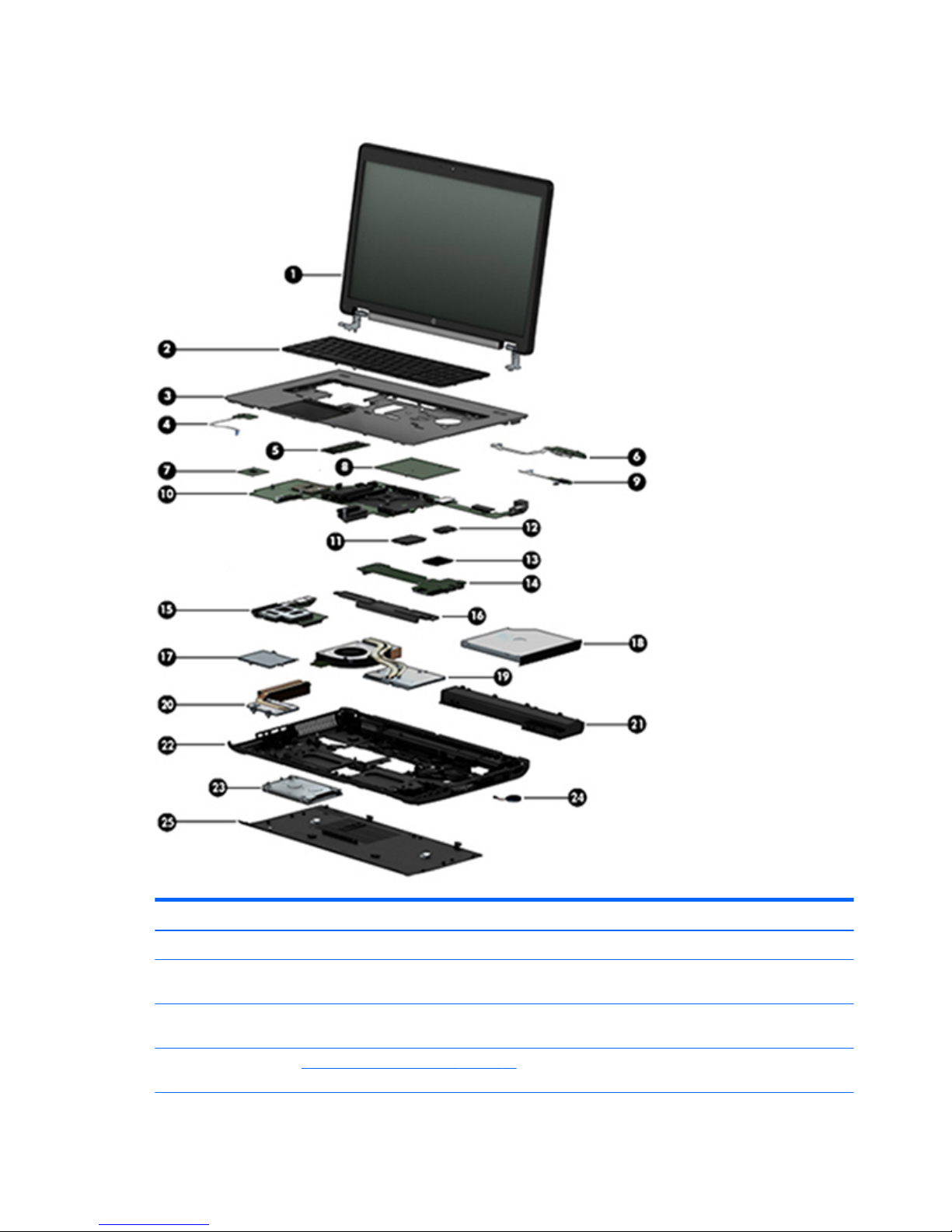
Computer major components
Item Description Spare part number
(1) Display assembly (includes microphone and wireless antenna cables):
17.3-in, AG, FHD, LED, UWVA display assembly for use on computer models equipped with a
webcam
784207-001
17.3-in, AG, FHD, LED, UWVA display assembly for use on computer models not equipped with
a webcam
784206-001
NOTE: See Display assembly components on page 27 for more display component information and spare part
numbers.
22 Chapter 3 Illustrated parts catalog
Page 35

Item Description Spare part number
(2) Keyboard with backlight and TouchPad (includes backlight, keyboard, and pointing stick cables):
For use in Belgium 733688-A41
For use in Brazil 733688-201
For use in Bulgaria 733688-261
For use in Canada 733688-DB1
For use in the Czech Republic and Slovakia 733688-FL1
For use in Denmark 733688-081
For use in France 733688-051
For use in Germany 733688-041
For use in Greece 733688-151
For use in Hungary 733688-211
For use in Iceland 733688-DD1
For use in India 733688-D61
For use in Israel 733688-BB1
For use in Italy 733688-061
For use in Japan 733688-291
For use in Latin America 733688-161
For use in the Netherlands 733688-B31
For use in Northwest Africa 733688-FP1
For use in Norway 733688-091
For use in Portugal 733688-131
For use in Romania 733688-271
For use in Russia 733688-251
For use in Saudi Arabia 733688-171
For use in Slovenia 733688-BA1
For use in South Korea 733688-AD1
For use in Spain 733688-071
For use in Sweden and Finland 733688-B71
For use in Switzerland 733688-BG1
For use in Taiwan 733688-AB1
For use in Thailand 733688-281
For use in Turkey 733688-141
For use in the United Kingdom and Singapore 733688-031
For use in the United States 733688-001
Computer major components 23
Page 36

Item Description Spare part number
(3) Top cover 735587-001
(4) Power button board (includes cable) 733636-001
(5) Memory modules (PC3L-12800, 1600-MHz, DDR3L):
8.0-GB 693374-001
4.0-GB 691740-001
(6) Fingerprint reader board (includes cable)
NOTE: The fingerprint reader board spare part kit does not include the fingerprint reader
board bracket. The fingerprint reader board bracket is included in the Bracket Kit, spare part
number 733637-001.
737730-001
(7) Processor (includes replacement thermal material):
Intel Core i7-4940MX 3.10-GHz (SC turbo up to 4.00-GHz) processor (1600-MHz FSB, 8.0-MB L3
cache, quad core, 8 threads, 57-W)
778694-001
Intel Core i7-4910MQ 2.90-GHz (SC turbo up to 3.90-GHz) processor (1600-MHz FSB, 8.0-MB L3
cache, quad core, 8 threads, 47-W)
778693-001
Intel Core i7-4810MQ 2.80-GHz (SC turbo up to 3.80-GHz) processor (1600-MHz FSB, 6.0-MB L3
cache, quad core, 8 threads, 47-W)
778692-001
Intel Core i7-4710MQ 2.50-GHz (SC turbo up to 3.50-GHz) processor (1600-MHz FSB, 6.0-MB L3
cache, quad core, 8 threads, 47-W)
773212-001
Intel Core i7-4610M 3.00-GHz (SC turbo up to 3.70-GHz) processor (1600-MHz FSB, 4.0-MB L3
cache, dual core, 4 threads, 37-W)
765141-001
Intel Core i5-4340M 2.90-GHz (SC turbo up to 3.60-GHz) processor (1600-MHz FSB, 3.0-MB L3
cache, dual core, 4 threads, 37-W)
765142-001
Intel Core i5-4210M 2.60-GHz (SC turbo up to 3.20-GHz) processor (1600-MHz FSB, 3.0-MB L3
cache, dual core, 4 threads, 37-W)
768420-001
(8) Graphics board (includes replacement thermal material):
AMD FirePro W6170M 786689-001
NVIDIA K1100M N15P-Q1 785214-001
NVIDIA Quadro K5100M 781701-001
NVIDIA Quadro K4100M 781702-001
NVIDIA Quadro K3100M 781703-001
NVIDIA Quadro K2200M 786688-001
(9) Multifunction board (includes LED light pipe) 733639-001
(10) System board (includes replacement thermal material):
For use only on computer models equipped with a quad core processor and the Windows 8
Professional operating system
784213-601
For use only on computer models equipped with a quad core processor and the Windows 8
Standard operating system
784213-501
For use only on computer models equipped with a quad core processor and a non-Windows 8
operating system
784213-001
24 Chapter 3 Illustrated parts catalog
Page 37

Item Description Spare part number
For use only on computer models equipped with a dual core processor and the Windows 8
Professional operating system
784212-601
For use only on computer models equipped with a dual core processor and the Windows 8
Standard operating system
784212-501
For use only on computer models equipped with a dual core processor and a non-Windows 8
operating system
784212-001
(11) Solid-state drive:
512 GB, SATA-3 795969-001
256 GB, SATA-3, SED, Opal2 795968-001
256 GB, SATA-3, SED, Opal1 795967-001
256 GB, SATA-3 795966-001
240 GB, SATA-3 795965-001
180 GB, SATA-3 795964-001
128 GB, SATA-3 795963-001
(12) WWAN module:
HP lt4111 LTE/EV-DO/HSPA+ Mobile Broadband Module 748021-001
HP lt4112 LTE/HSPA+ Mobile Broadband Module 740011-001
HP hs3110 HSPA+ Mobile Broadband Module 748599-001
(13) WLAN module:
WLAN Intel Dual Band Wireless-AC 7260 802.11 ac 2×2 WiFi + Bluetooth 4.0 Combo Adapter 710663-001
WLAN Intel Dual Band Wireless-N 7260AN 802.11 a/b/g/n 2×2 WiFi + Bluetooth 4.0
Combo Adapter
717379-001
WLAN Intel Dual Band Wireless-N 7260AN 802.11 a/b/g/n 2×2 WiFi + Bluetooth 4.0
Combo Adapter
747833-001
WLAN Intel Dual Band Wireless-N 7260NB 802.11 a/b/g/n 2×2 WiFi adapter 717380-001
(14) Audio/USB board (includes audio jack and USB port) 737732-001
(15) ExpressCard assembly 794578-001
(16) Speakers (include left and right speakers and cables) 733638-001
(17) Smart Card reader (includes cable) 742159-001
(18) Optical drive for use in Upgrade Bay (includes bezel and bracket):
Blu-ray R/RE DVD±RW SuperMulti Double-Layer Drive 735600-001
Blu-ray ROM DVD±RW SuperMulti Double-Layer Drive 735599-001
DVD±RW SuperMulti Double-Layer Drive 735602-001
Upgrade Bay hard drive carrier 734298-001
(19) Graphics subsystem heat sink (includes replacement thermal material):
For use only on computer models equipped with the NVIDIA Quadro K5100M graphics board 735373-001
Computer major components 25
Page 38

Item Description Spare part number
For use only on computer models equipped with the NVIDIA Quadro K4100M or K3100M
graphics board
735374-001
For use only on computer models equipped with the NVIDIA Quadro K610M graphics board 735375-001
For use only on computer models equipped with the MXM-Emerald graphics board 786687-001
For use only on computer models equipped with the MXM-N15P-15 graphics board 786686-001
For use only on computer models equipped with the MXM-N15P-Q1 graphics board (includes
fan)
768730-001
(20) Processor heat sink (includes replacement thermal material):
For use only on computer models equipped with a quad core processor 735372-001
For use only on computer models equipped with a dual core processor 735371-001
(21) Battery:
8-cell, 2.80-AHr, 83-WHr, Li-ion 708456-001
8-cell, 2.80-AHr, 75-WHr, Li-ion 708455-001
(22) Base enclosure (includes latches) 785211-001
(23) Hard drive:
NOTE: The hard drive spare part kit does not include the hard drive bracket, cover, or screws. The hard drive bracket,
cover, and screws are included in the Hard Drive Hardware Kit, spare part number 734280-001.
1-TB, 7200-RPM, SATA, 9.5-mm 766644-001
1-TB, 5400-RPM, SATA, 7.0-mm 778192-001
750-GB, 7200-RPM, SATA, 7.0-mm 778191-001
500-GB, 7200-RPM, SATA, 7.0-mm 703267-001
500-GB, 7200-RPM, SED, 7.0-mm 703268-001
500-GB, 5400-RPM, SATA, FIPS, 7.0-mm 730946-001
(24) RTC battery (includes cable and double-sided adhesive) 734300-001
(25) Service cover 733635-001
26 Chapter 3 Illustrated parts catalog
Page 39
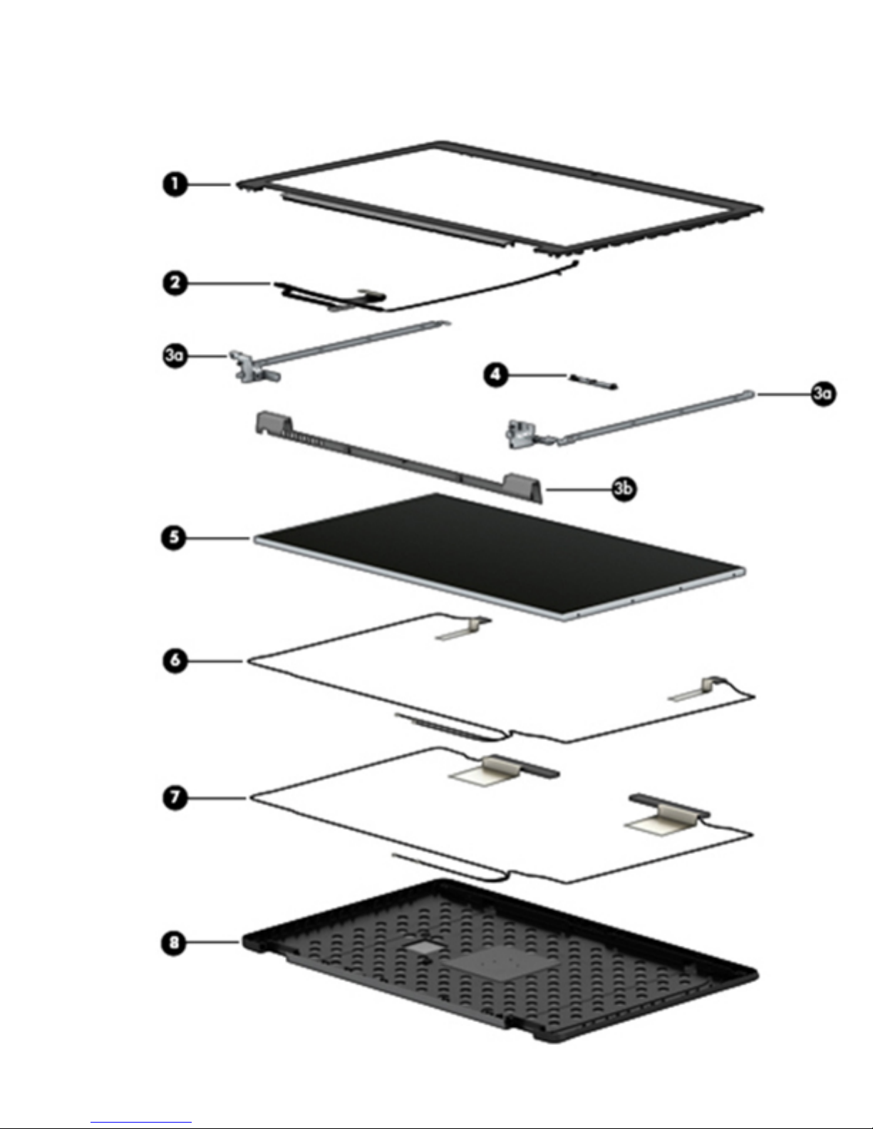
Display assembly components
Display assembly components 27
Page 40

Item Description Spare part number
(1) Display bezel:
For use only on computer models equipped with a webcam 733633-001
For use only on computer models not equipped a webcam 735589-001
(2) Display panel cable: Included in the Cable Kit, spare part number 785212-001 (includes webcam module cable)
Display Hinge Kit, includes: 733634-001
(3a) Left and right hinges
(3b) Hinge cover
Hinge brackets (not illustrated)
(4) Webcam/microphone module 784208-001
Microphone module (not illustrated) 735370-001
(5) Display panel:
17.3-in, FHD, AG, LED, WVA display panel 735367-001
17.3-in, HD, AG, LED, WVA display panel 735366-001
Display Panel Support Kit, includes: 784211-001
(6) WLAN antenna cables and transceivers
(7) WWAN antenna cables and transceivers
(8) Display enclosure (also available using spare part number 740477-001)
Low-voltage differential signalling board (not illustrated) 741282-001
28 Chapter 3 Illustrated parts catalog
Page 41
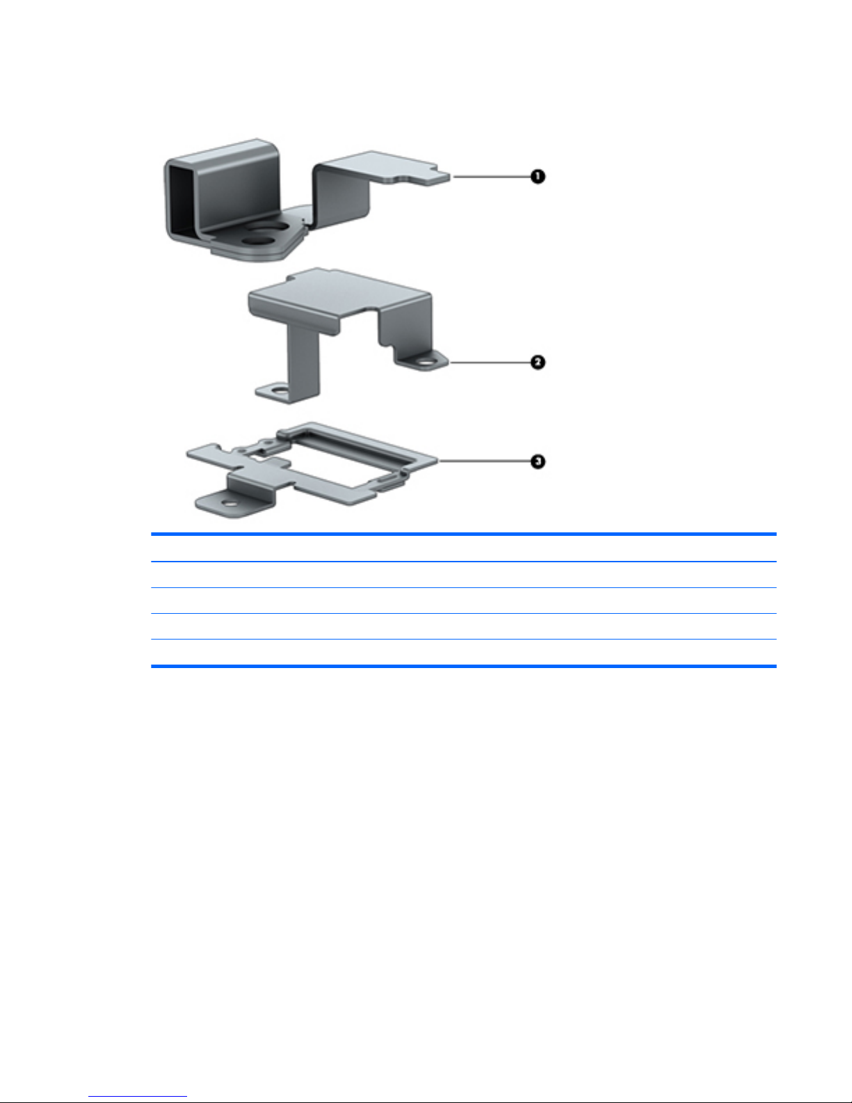
Bracket Kit
Item Description Spare part number
Bracket Kit 737734-001
(1) Power connector/security lock bracket
(2) RJ-45 bracket
(3) Fingerprint reader bracket
Bracket Kit 29
Page 42
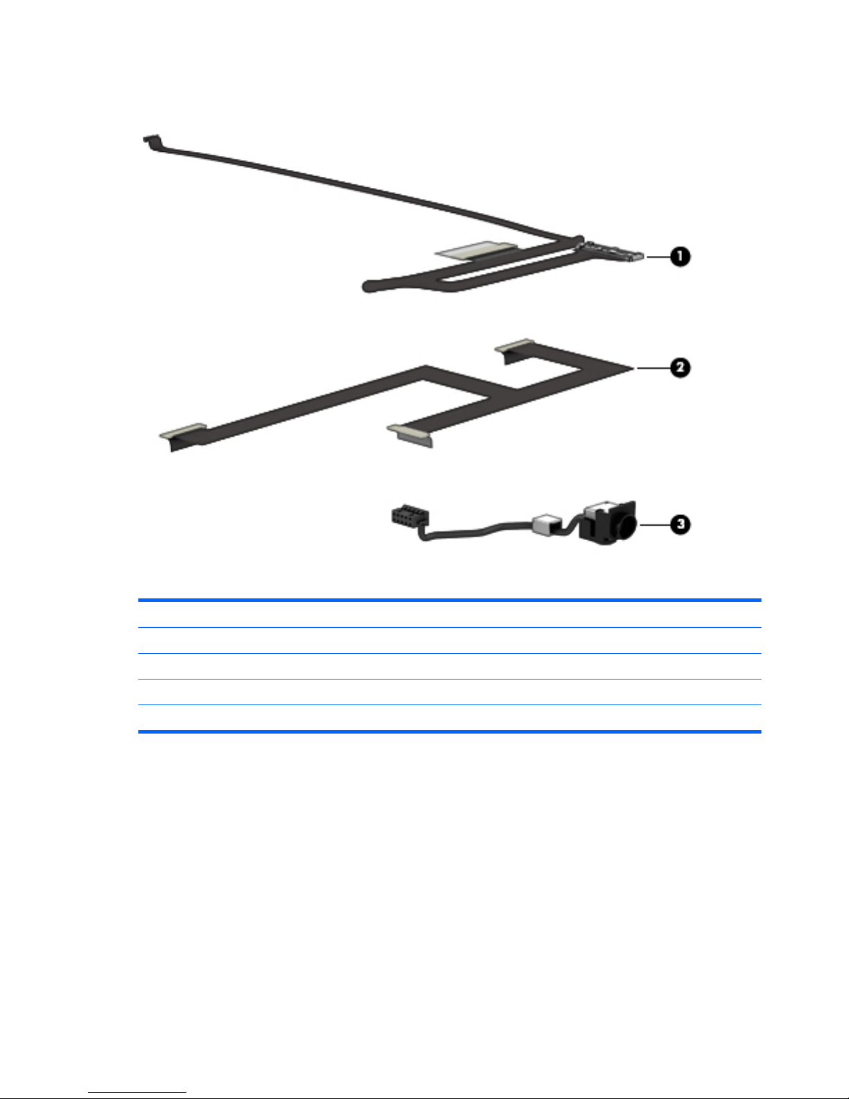
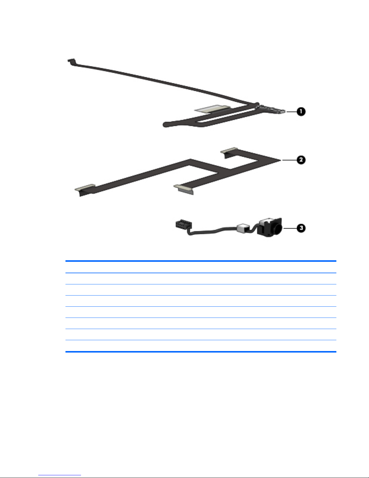
Cable Kit
Item Description Spare part number
Cable Kit 785212-001
(1) Display panel cable (includes webcam/microphone module cable)
(2) Low-voltage differential signalling board cable
(3) Power connector cable
30 Chapter 3 Illustrated parts catalog
Page 43
Plastics Kit
Item Description Spare part number
Plastics Kit 733637-001
(1) Rear corner cover/right
(2) Rear corner cover/left
(3) Fingerprint reader bezel
(4) SD Card reader bezel
(5) ExpressCard bezel
Fingerprint reader cover (not illustrated)
Plastics Kit 31
Page 44
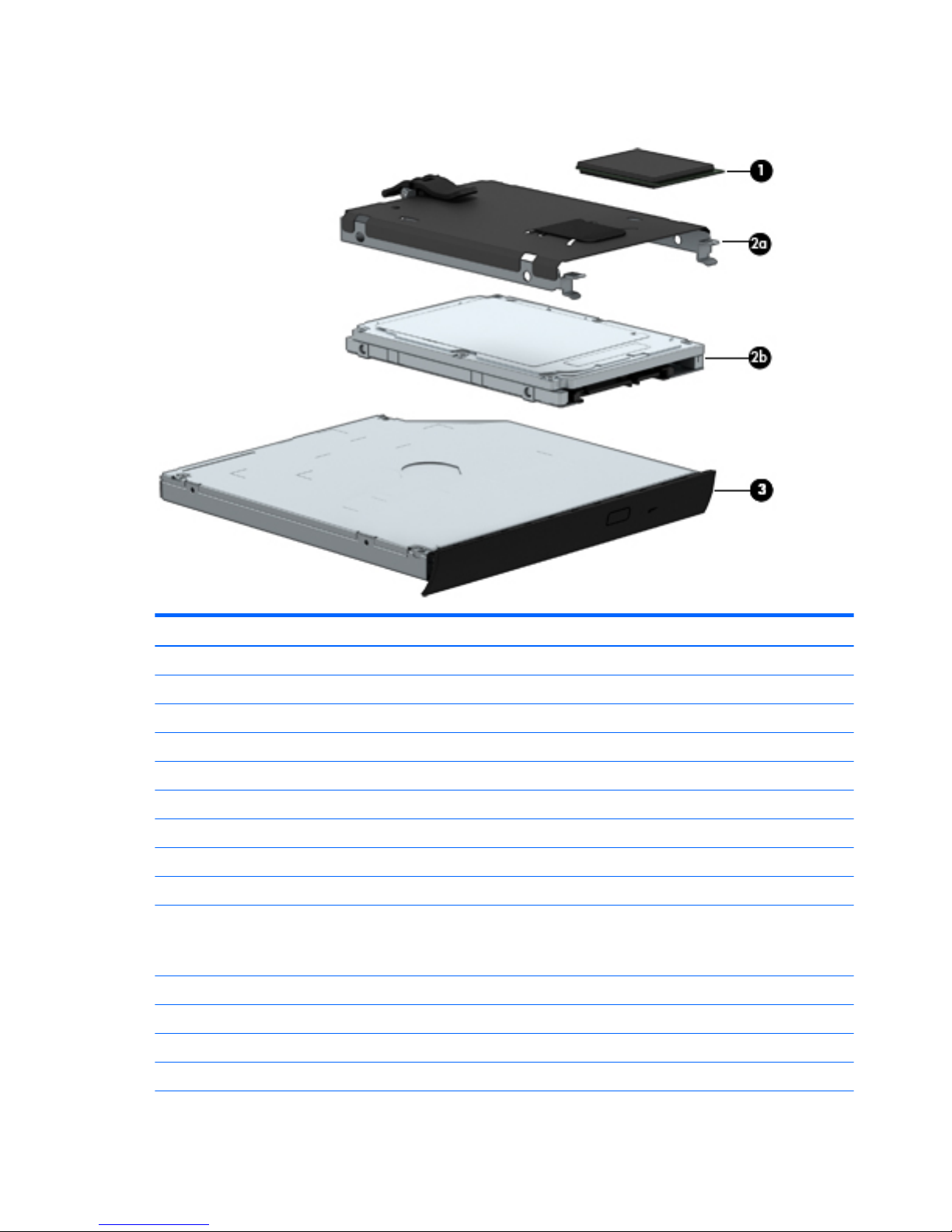
Mass storage devices
Item Description Spare part number
(1) Solid-state drive:
512 GB, SATA-3 795969-001
256 GB, SATA-3, SED, Opal2 795968-001
256 GB, SATA-3, SED, Opal1 795967-001
256 GB, SATA-3 795966-001
240 GB, SATA-3 795965-001
180 GB, SATA-3 795964-001
128 GB, SATA-3 795963-001
(2a) Hard Drive Hardware Kit (includes hard drive bracket, cover, and screws) 734280-001
(2b) Hard drive:
NOTE: The hard drive spare part kit does not include the hard drive bracket, cover, or screws. The hard drive bracket,
cover, and screws are included in the Hard Drive Hardware Kit, spare part number 734280-001.
1-TB, 7200-RPM, SATA, 9.5-mm 766644-001
1-TB, 5400-RPM, SATA, 7.0-mm 778192-001
750-GB, 7200-RPM, SATA, 7.0-mm 778191-001
500-GB, 7200-RPM, SATA, 7.0-mm 703267-001
32 Chapter 3 Illustrated parts catalog
Page 45

Item Description Spare part number
500-GB, 7200-RPM, SED, 7.0-mm 703268-001
500-GB, 5400-RPM, SATA, FIPS, 7.0-mm 730946-001
(3) Optical drive for use in Upgrade Bay (includes bezel and bracket):
Blu-ray R/RE DVD±RW SuperMulti Double-Layer Drive 735600-001
Blu-ray ROM DVD±RW SuperMulti Double-Layer Drive 735599-001
DVD±RW SuperMulti Double-Layer Drive 735602-001
Upgrade Bay hard drive carrier (not illustrated) 734298-001
Miscellaneous parts
Description Spare part number
AC Adapter:
230-W HP Smart AC adapter (PFC) 693706-001
200-W HP Smart AC adapter (PFC) 693708-001
HP professional slim top-load carrying case 703888-001
HP DisplayPort-to-HDMI adapter 749288-001
Upgrade Bay hard drive carrier 734298-001
HP cable lock for use on the docking station 575921-001
HP Ultraslim keyed cable lock 703372-001
HP USB laser mouse 674318-001
Power cord (3-pin, black,1.83-m):
For use in Asia Pacific countries and regions 491683-D91
For use in Argentina 491683-D01
For use in Australia 491683-011
For use in Belgium 491683-A41
For use in Brazil 491683-202
For use in the Czech Republic and Slovakia 491683-221
For use in Denmark 491683-081
For use in Europe 491683-021
For use in France 491683-051
For use in Germany 491683-041
For use in Greece 491683-151
For use in India 491683-D61
For use in Israel 491683-BB1
Miscellaneous parts 33
Page 46

Description Spare part number
For use in Italy 491683-061
For use in Japan 491683-291
For use in North America 491683-001
For use in the Netherlands 491683-B91
For use in North Africa 491683-DE1
For use in Norway 491683-091
For use in Portugal 491683-131
For use in the People's Republic of China 491683-AA1
For use in Saudi Arabia 491683-171
For use in Singapore 491683-AF1
For use in South Korea 491683-AD1
For use in Sweden and Finland 491683-101
For use in Switzerland 491683-111
For use in Taiwan 491683-AB1
For use in Thailand 491683-201
For use in Turkey 491683-141
For use in the United Kingdom 491683-031
Screw Kit 741619-001
Sequential part number listing
Spare part number Description
491683-001 Power cord for use in North America (3-pin, black, 1.83-m)
491683-011 Power cord for use in Australia (3-pin, black, 1.83-m)
491683-021 Power cord for use in Europe (3-pin, black, 1.83-m)
491683-031 Power cord for use in the United Kingdom (3-pin, black, 1.83-m)
491683-041 Power cord for use in Germany (3-pin, black, 1.83-m)
491683-051 Power cord for use in France (3-pin, black, 1.83-m)
491683-061 Power cord for use in Italy (3-pin, black, 1.83-m)
491683-081 Power cord for use in Denmark (3-pin, black, 1.83-m)
491683-091 Power cord for use in Norway (3-pin, black, 1.83-m)
491683-101 Power cord for use in Sweden and Finland (3-pin, black, 1.83-m)
491683-111 Power cord for use in Switzerland (3-pin, black, 1.83-m)
491683-131 Power cord for use in Portugal (3-pin, black, 1.83-m)
34 Chapter 3 Illustrated parts catalog
Page 47

Spare part number Description
491683-141 Power cord for use in Turkey (3-pin, black, 1.83-m)
491683-151 Power cord for use in Latin America (3-pin, black, 1.83-m)
491683-171 Power cord for use in Saudi Arabia (3-pin, black, 1.83-m)
491683-201 Power cord for use in Thailand (3-pin, black, 1.83-m)
491683-202 Power cord for use in Brazil (3-pin, black, 1.83-m)
491683-221 Power cord for use in the Czech Republic and Slovakia (3-pin, black, 1.83-m)
491683-291 Power cord for use in Japan (3-pin, black, 1.83-m)
491683-A41 Power cord for use in Belgium (3-pin, black, 1.83-m)
491683-AA1 Power cord for use in the People's Republic of China (3-pin, black, 1.83-m)
491683-AB1 Power cord for use in Taiwan (3-pin, black, 1.83-m)
491683-AD1 Power cord for use in South Korea (3-pin, black, 1.83-m)
491683-AF1 Power cord for use in Singapore (3-pin, black, 1.83-m)
491683-B91 Power cord for use in the Netherlands (3-pin, black, 1.83-m)
491683-BB1 Power cord for use in Israel (3-pin, black, 1.83-m)
491683-D01 Power cord for use in Argentina (3-pin, black, 1.83-m)
491683-D61 Power cord for use in India (3-pin, black, 1.83-m)
491683-D91 Power cord for use in Asia Pacific countries and regions (3-pin, black, 1.83-m)
491683-DE1 Power cord for use in Northwest Africa (3-pin, black, 1.83-m)
575921-001 HP cable lock for use on the docking station
674318-001 HP USB laser mouse
691740-001 4.0-GB memory module (PC3L-12800, 1600 MHz)
693374-001 8.0-GB memory module (PC3L-12800, 1600 MHz)
693706-001 230-W HP Smart AC adapter (PFC)
693708-001 200-W HP Smart AC adapter (PFC)
703267-001 500-GB, 7200-rpm, 7.0-mm, SATA hard drive (does not include hard drive bracket, cover, or screws)
NOTE: The hard drive bracket, cover, and screws are included in the Hard Drive Hardware Kit, spare part
number 734280-001.
703268-001 500-GB, 7200-rpm, 7.0-mm, SED hard drive (does not include hard drive bracket, cover, or screws)
NOTE: The hard drive bracket, cover, and screws are included in the Hard Drive Hardware Kit, spare part
number 734280-001.
703372-001 HP Ultraslim keyed cable lock
703888-001 HP professional slim top-load carrying case
708455-001 Battery, 8-cell, 2.8-AHr, 75-WHr, Li-ion
708456-001 Battery, 8-cell, 2.8-AHr, 83-WHr, Li-ion
710663-001 Intel Dual Band Wireless-AC 7260 802.11 ac 2×2 WiFi + Bluetooth 4.0 Combo Adapter
Sequential part number listing 35
Page 48

Spare part number Description
717379-001 Intel Dual Band Wireless-N 7260AN 802.11 a/b/g/n 2×2 WiFi + Bluetooth 4.0 Combo Adapter
717380-001 Intel Dual Band Wireless-N 7260NB 802.11 a/b/g/n 2×2 WiFi adapter
730946-001 500-GB, 5400-rpm, 7.0-mm, SATA, FIPS hard drive (does not include hard drive bracket, cover, or screws)
NOTE: The hard drive bracket, cover, and screws are included in the Hard Drive Hardware Kit, spare part
number 734280-001.
733633-001 Display bezel for use on computer models equipped with a webcam
733634-001 Display Hinge Kit (includes left and right hinges, hinge cover, and bracket)
733635-001 Service cover
733636-001 Power button board (includes cable)
733637-001 Plastics Kit (includes ExpressCard bezel, fingerprint reader bracket, fingerprint reader insert, rear corner cover/
left, rear corner cover/right, and SD card reader bezel).
NOTE: See Plastics Kit on page 31 for more Plastics Kit information.
733638-001 Speakers (include left and right speakers and cables)
733639-001 Multifunction board (includes LED light pipe)
733688-001 Keyboard with backlight and TouchPad for use in the United States (includes backlight, keyboard, and pointing
stick cables)
733688-031 Keyboard with backlight and TouchPad for use in the United Kingdom and Singapore (includes backlight,
keyboard, and pointing stick cables)
733688-041 Keyboard with backlight and TouchPad for use in Germany (includes backlight, keyboard, and pointing stick
cables)
733688-051 Keyboard with backlight and TouchPad for use in France (includes backlight, keyboard, and pointing stick
cables)
733688-061 Keyboard with backlight and TouchPad for use in Italy (includes backlight, keyboard, and pointing stick cables)
733688-071 Keyboard with backlight and TouchPad for use in Spain (includes backlight, keyboard, and pointing stick
cables)
733688-081 Keyboard with backlight and TouchPad for use in Denmark (includes backlight, keyboard, and pointing stick
cables)
733688-091 Keyboard with backlight and TouchPad for use in Norway (includes backlight, keyboard, and pointing stick
cables)
733688-131 Keyboard with backlight and TouchPad for use in Portugal (includes backlight, keyboard, and pointing stick
cables)
733688-141 Keyboard with backlight and TouchPad for use in Turkey (includes backlight, keyboard, and pointing stick
cables)
733688-151 Keyboard with backlight and TouchPad for use in Greece (includes backlight, keyboard, and pointing stick
cables)
733688-161 Keyboard with backlight and TouchPad for use in Latin America (includes backlight, keyboard, and pointing
stick cables)
733688-171 Keyboard with backlight and TouchPad for use in Saudi Arabia (includes backlight, keyboard, and pointing stick
cables)
733688-201 Keyboard with backlight and TouchPad for use in Brazil (includes backlight, keyboard, and pointing stick
cables)
36 Chapter 3 Illustrated parts catalog
Page 49

Spare part number Description
733688-211 Keyboard with backlight and TouchPad for use in Hungary(includes backlight, keyboard, and pointing stick
cables)
733688-251 Keyboard with backlight and TouchPad for use in Russia (includes backlight, keyboard, and pointing stick
cables)
733688-261 Keyboard with backlight and TouchPad for use in Bulgaria (includes backlight, keyboard, and pointing stick
cables)
733688-271 Keyboard with backlight and TouchPad for use in Romania (includes backlight, keyboard, and pointing stick
cables)
733688-281 Keyboard with backlight and TouchPad for use in Thailand (includes backlight, keyboard, and pointing stick
cables)
733688-291 Keyboard with backlight and TouchPad for use in Japan (includes backlight, keyboard, and pointing stick
cables)
733688-A41 Keyboard with backlight and TouchPad for use in Belgium (includes backlight, keyboard, and pointing stick
cables)
733688-AB1 Keyboard with backlight and TouchPad for use in Taiwan (includes backlight, keyboard, and pointing stick
cables)
733688-AD1 Keyboard with backlight and TouchPad for use in South Korea (includes backlight, keyboard, and pointing stick
cables)
733688-B31 Keyboard with backlight and TouchPad for use in the Netherlands (includes backlight, keyboard, and pointing
stick cables)
733688-B71 Keyboard with backlight and TouchPad for use in Sweden and Finland (includes backlight, keyboard, and
pointing stick cables)
733688-BA1 Keyboard with backlight and TouchPad for use in Slovenia (includes backlight, keyboard, and pointing stick
cables)
733688-BB1 Keyboard with backlight and TouchPad for use in Israel (includes backlight, keyboard, and pointing stick
cables)
733688-BG1 Keyboard with backlight and TouchPad for use in Switzerland (includes backlight, keyboard, and pointing stick
cables)
733688-D61 Keyboard with backlight and TouchPad for use in India (includes backlight, keyboard, and pointing stick cables)
733688-DB1 Keyboard with backlight and TouchPad for use in Canada (includes backlight, keyboard, and pointing stick
cables)
733688-DD1 Keyboard with backlight and TouchPad for use in Iceland (includes backlight, keyboard, and pointing stick
cables)
733688-FL1 Keyboard with backlight and TouchPad for use in the Czech Republic and Slovakia (includes backlight,
keyboard, and pointing stick cables)
733688-FP1 Keyboard with backlight and TouchPad for use in Northwest Africa (includes backlight, keyboard, and pointing
stick cables)
734280-001 Hard Drive Hardware Kit (includes the hard drive bracket, cover, and screws)
734298-001 Upgrade Bay hard drive carrier
734300-001 RTC battery (includes cable and double-sided adhesive)
735366-001 Display panel (17.3-in, HD+, AG, LED, WVA)
735367-001 Display panel (17.3-in, FHD, AG, LED, WVA)
Sequential part number listing 37
Page 50

Spare part number Description
735370-001 Microphone module (includes double-sided adhesive)
735371-001 Processor heat sink for use only on computer models equipped with a dual core processor (includes
replacement thermal material)
735372-001 Processor heat sink for use only on computer models equipped with a quad core processor (includes
replacement thermal material)
735373-001 Graphics subsystem heat sink for use only on computer models equipped with the NVIDIA Quadro K5100M
graphics board (includes replacement thermal material)
735374-001 Graphics subsystem heat sink for use only on computer models equipped with the NVIDIA Quadro K4100M or
K3100M graphics board (includes replacement thermal material)
735375-001 Graphics subsystem heat sink for use only on computer models equipped with a 50-W graphics subsystem
(includes replacement thermal material)
735587-001 Top cover
735589-001 Display bezel for use only on computer models not equipped with a webcam
735599-001 Blu-ray ROM DVD±RW SuperMulti Double-Layer Drive (includes bezel and bracket)
735600-001 Blu-ray R/RE DVD±RW SuperMulti Double-Layer Drive (includes bezel and bracket)
735602-001 DVD±RW SuperMulti Double-Layer Drive (includes bezel and bracket)
737730-001 Fingerprint reader board (includes cable)
737732-001 Audio/USB board (includes audio jack and USB port)
737734-001 Bracket Kit (includes fingerprint reader bracket, RJ-45 bracket, power connector bracket/security lock)
NOTE: See Bracket Kit on page 29 for more Bracket Kit information.
740011-001 HP lt4112 LTE/HSPA+ Mobile Broadband Module
740477-001 Display enclosure
NOTE: The display enclosure is also available in the Display Panel Support Kit, spare part number
784211-001.
741282-001 Display low-voltage differential signalling board
741619-001 Screw Kit
742159-001 Smart Card reader (includes cable)
747833-001 Intel Dual Band Wireless-N 7260AN 802.11 a/b/g/n 2×2 WiFi + Bluetooth 4.0 Combo Adapter
748021-001 HP lt4111 LTE/EV-DO/HSPA+ Mobile Broadband Module
748599-001 HP hs3110 HSPA+ Mobile Broadband Module
749288-001 HP DisplayPort-to-HDMI adapter
765141-001 Intel Core i7-4610M 3.00-GHz (SC turbo up to 3.70-GHz) processor (1600-MHz FSB, 4.0-MB L3 cache, dual core,
4 threads, 37-W; includes replacement thermal material)
765142-001 Intel Core i5-4340M 2.90-GHz (SC turbo up to 3.60-GHz) processor (1600-MHz FSB, 3.0-MB L3 cache, dual core,
4 threads, 37-W; includes replacement thermal material)
766644-001 1-TB, 7200-rpm, 9.5-mm, SATA hard drive (does not include hard drive bracket, cover, or screws)
NOTE: The hard drive bracket, cover, and screws are included in the Hard Drive Hardware Kit, spare part
number 734280-001.
38 Chapter 3 Illustrated parts catalog
Page 51

Spare part number Description
768420-001 Intel Core i5-4210M 2.60-GHz (SC turbo up to 3.20-GHz) processor (1600-MHz FSB, 3.0-MB L3 cache, dual core,
4 threads, 37-W; includes replacement thermal material)
768730-001 Graphics subsystem heat sink with fan for use only on computer models equipped with the N15P-Q1
graphics board (includes replacement thermal material)
773212-001 Intel Core i7-4710MQ 2.50-GHz (SC turbo up to 3.50-GHz) processor (1600-MHz FSB, 6.0-MB L3 cache, quad
core, 8 threads, 47-W; includes replacement thermal material)
778191-001 750-GB, 7200-rpm, 7.0-mm, SATA hard drive (does not include hard drive bracket, cover, or screws)
NOTE: The hard drive bracket, cover, and screws are included in the Hard Drive Hardware Kit, spare part
number 734280-001.
778192-001 1-TB, 5400-rpm, 7.0-mm, SATA hard drive (does not include hard drive bracket, cover, or screws)
NOTE: The hard drive bracket, cover, and screws are included in the Hard Drive Hardware Kit, spare part
number 734280-001.
778692-001 Intel Core i7-4810MQ 2.80-GHz (SC turbo up to 3.80-GHz) processor (1600-MHz FSB, 6.0-MB L3 cache, quad
core, 8 threads, 47-W; includes replacement thermal material)
778693-001 Intel Core i7-4910MQ 2.90-GHz (SC turbo up to 3.90-GHz) processor (1600-MHz FSB, 8.0-MB L3 cache, quad
core, 8 threads, 47-W; includes replacement thermal material)
778694-001 Intel Core i7-4940MX 3.10-GHz (SC turbo up to 4.00-GHz) processor (1600-MHz FSB, 8.0-MB L3 cache, quad
core, 8 threads, 57-W; includes replacement thermal material)
781701-001 NVIDIA Quadro K5100M graphics board (includes replacement thermal material)
781702-001 NVIDIA Quadro K4100M graphics board (includes replacement thermal material)
781703-001 NVIDIA Quadro K3100M graphics board (includes replacement thermal material)
784206-001 17.3-in, AG, FHD, LED, UWVA display assembly for use on computer models not equipped with a webcam
(includes microphone and wireless antenna cables)
784207-001 17.3-in, AG, FHD, LED, UWVA display assembly for use on computer models equipped with a webcam (includes
microphone, webcam, and wireless antenna cables)
784208-001 Webcam/microphone module (includes double-sided adhesive)
784211-001 Display Panel Support Kit (includes the display enclosure, screw covers, WLAN antenna cables and
transceivers, and WWAN antenna cables and transceivers)
784212-001 System board for use only on computer models equipped with a dual core processor and a non-Windows 8
operating system (includes replacement thermal material)
784212-501 System board for use only on computer models equipped with a dual core processor and the Windows 8
Standard operating system (includes replacement thermal material)
784212-601 System board for use only on computer models equipped with a dual core processor and the Windows 8
Professional operating system (includes replacement thermal material)
784213-001 System board for use only on computer models equipped with a quad core processor and a non-Windows 8
operating system (includes replacement thermal material)
784213-501 System board for use only on computer models equipped with a quad core processor and the Windows 8
Standard operating system (includes replacement thermal material)
784213-601 System board for use only on computer models equipped with a quad core processor and the Windows 8
Professional operating system (includes replacement thermal material)
785211-001 Base enclosure (includes latches)
785212-001 Cable Kit (includes the display panel/webcam cable, low-voltage differential signalling board cable, and the
power connector cable)
Sequential part number listing 39
Page 52

Spare part number Description
NOTE: See Cable Kit on page 30 for more Cable Kit information.
785214-001 NVIDIA K1100M N15P-Q1 graphics board
786686-001 Graphics subsystem heat sink for use on computer models equipped with the MXM-N15P-Q5 graphics board
786687-001 Graphics subsystem heat sink for use on computer models equipped with the MXM-Emerald graphics board
786688-001 NVIDIA Quadro K2200M graphics board
786689-001 AMD FirePro W6170M graphics board
794578-001 ExpressCard assembly
794731-001 256-GB solid-state drive, M2
795963-001 128-GB solid-state drive, SATA-3
795964-001 180-GB solid-state drive, SATA-3
795965-001 240-GB solid-state drive, SATA-3
795966-001 256-GB solid-state drive, SATA-3
795967-001 256-GB solid-state drive, SATA-3, SED, Opal1
795968-001 256-GB solid-state drive, SATA-3, SED, Opal2
795969-001 512-GB solid-state drive, SATA-3
40 Chapter 3 Illustrated parts catalog
Page 53

4 Removal and replacement procedures
preliminary requirements
Tools required
You will need the following tools to complete the removal and replacement procedures:
●
Flat-bladed screwdriver
●
Magnetic screwdriver
●
Phillips P0 and P1 screwdrivers
●
Torx T8 screwdriver
●
5.0 mm hex socket driver
Service considerations
The following sections include some of the considerations that you must keep in mind during disassembly
and assembly procedures.
NOTE: As you remove each subassembly from the computer, place the subassembly (and all accompanying
screws) away from the work area to prevent damage.
Plastic parts
Using excessive force during disassembly and reassembly can damage plastic parts. Use care when handling
the plastic parts. Apply pressure only at the points designated in the maintenance instructions.
Cables and and pointing stick connectors
CAUTION: When servicing the computer, be sure that cables are placed in their proper locations during the
reassembly process. Improper cable placement can damage the computer.
Cables must be handled with extreme care to avoid damage. Apply only the tension required to unseat or
seat the cables during removal and insertion. Handle cables by the connector whenever possible. In all cases,
avoid bending, twisting, or tearing cables. Be sure that cables are routed in such a way that they cannot be
caught or snagged by parts being removed or replaced. Handle flex cables with extreme care; these cables
tear easily.
Tools required 41
Page 54

Drive handling
CAUTION: Drives are fragile components that must be handled with care. To prevent damage to the
computer, damage to a drive, or loss of information, observe these precautions:
Before removing or inserting a hard drive, shut down the computer. If you are unsure whether the computer
is off or in Hibernation, turn the computer on, and then shut it down through the operating system.
Before handling a drive, be sure that you are discharged of static electricity. While handling a drive, avoid
touching the connector.
Before removing a diskette drive or optical drive, be sure that a diskette or disc is not in the drive and be sure
that the optical drive tray is closed.
Handle drives on surfaces covered with at least one inch of shock-proof foam.
Avoid dropping drives from any height onto any surface.
After removing a hard drive, an optical drive, or a diskette drive, place it in a static-proof bag.
Avoid exposing a hard drive to products that have magnetic fields, such as monitors or speakers.
Avoid exposing a drive to temperature extremes or liquids.
If a drive must be mailed, place the drive in a bubble pack mailer or other suitable form of protective
packaging and label the package “FRAGILE.”
Grounding guidelines
Electrostatic discharge damage
Electronic components are sensitive to electrostatic discharge (ESD). Circuitry design and structure
determine the degree of sensitivity. Networks built into many integrated and pointing stick circuits provide
some protection, but in many cases, ESD contains enough power to alter device parameters or melt
silicon junctions.
A discharge of static electricity from a finger or other conductor can destroy static-sensitive devices or
microcircuitry. Even if the spark is neither felt nor heard, damage may have occurred.
An electronic device exposed to ESD may not be affected at all and and pointing stick can work perfectly
throughout a normal cycle. Or the device may function normally for a while, then degrade in the internal
layers, reducing its life expectancy.
CAUTION: To prevent damage to the computer when you are removing or installing internal components,
observe these precautions:
Keep components in their electrostatic-safe containers until you area ready to install them.
Use nonmagnetic tools.
Before touching an electronic component, discharge static electricity by using the guidelines described in this
section.
Avoid touching pins, leads, and pointing stick circuitry. Handle electronic components as little as possible.
If you remove a component, place it in an electrostatic-safe container.
The following table shows how humidity affects the electrostatic voltage levels generated by different
activities.
CAUTION: A product can be degraded by as little as 700 V.
42 Chapter 4 Removal and replacement procedures preliminary requirements
Page 55

Typical electrostatic voltage levels
Relative humidity
Event 10% 40% 55%
Walking across carpet 35,000 V 15,000 V 7,500 V
Walking across vinyl floor 12,000 V 5,000 V 3,000 V
Motions of bench worker 6,000 V 800 V 400 V
Removing DIPS from plastic tube 2,000 V 700 V 400 V
Removing DIPS from vinyl tray 11,500 V 4,000 V 2,000 V
Removing DIPS from Styrofoam 14,500 V 5,000 V 3,500 V
Removing bubble pack from PCB 26,500 V 20,000 V 7,000 V
Packing PCBs in foam-lined box 21,000 V 11,000 V 5,000 V
Packaging and transporting guidelines
Follow these grounding guidelines when packaging and transporting equipment:
●
To avoid hand and pointing stick contact, transport products in static-safe tubes, bags, or boxes.
●
Protect ESD-sensitive parts and assemblies with conductive or approved and pointing stick containers
or packaging.
●
Keep ESD-sensitive parts in their containers until the parts arrive at static-free workstations.
●
Place items on a grounded surface before removing items from their containers.
●
Always be properly grounded when touching a component or assembly.
●
Store reusable ESD-sensitive parts from assemblies in protective packaging or nonconductive foam.
●
Use transporters and pointing stick conveyors made of antistatic belts and roller bushings. Be sure that
mechanized equipment used for moving materials is wired to ground and that proper materials are
selected to avoid static charging. When grounding is not possible, use an ionizer to dissipate electric
charges.
Workstation guidelines
Follow these grounding workstation guidelines:
●
Cover the workstation with approved static-shielding material.
●
Use a wrist strap connected to a properly grounded work surface and use properly grounded tools and
equipment.
●
Use conductive field service tools, such as cutters, screwdrivers, and vacuums.
●
When fixtures must directly contact dissipative surfaces, use fixtures made only of static-safe
materials.
●
Keep the work area free of non conductive materials, such as ordinary plastic assembly aids and
Styrofoam.
●
Handle ESD-sensitive components, parts, and assemblies by the case or PCM laminate. Handle these
items only at static-free workstations.
Grounding guidelines 43
Page 56

●
Avoid and pointing stick contact with pins, leads, or circuitry.
●
Turn off power and input signals before inserting or removing connectors or test equipment.
Equipment guidelines
Grounding equipment must include either a wrist strap or a foot strap at a grounded workstation.
●
When seated, wear a wrist strap connected to a grounded system. Wrist straps are flexible straps with a
minimum of one megohm ±10% resistance in the ground and pointing stick cords. To provide proper
ground, wear a strap snugly against the skin at all times. On grounded mats with banana-plug
connectors, use alligator clips to connect a wrist strap.
●
When standing, use foot straps and a grounded floor mat. Foot straps (heel, toe, or boot straps) can be
used at standing workstations and are compatible with most types of shoes or boots. On conductive
floors or dissipative floor mats, use foot straps on both feet with a minimum of one megohm resistance
between the operator and ground. To be effective, the conductive strips must be worn in contact with
the skin.
The following grounding equipment is recommended to prevent electrostatic damage:
●
Antistatic tape
●
Antistatic smocks, aprons, and sleeve protectors
●
Conductive bins and other assembly or soldering aids
●
Nonconductive foam
●
Conductive tabletop workstations with ground and pointing stick cords of one megohm resistance
●
Static-dissipative tables or floor mats with hard ties to the ground
●
Field service kits
●
Static awareness labels
●
Material-handling packages
●
Non conductive plastic bags, tubes, or boxes
●
Metal tote boxes
●
Electrostatic voltage levels and protective materials
The following table lists the shielding protection provided by antistatic bags and floor mats.
Material Use Voltage protection level
Antistatic plastic Bags 1,500 V
Carbon-loaded plastic Floor mats 7,500 V
Metallized laminate Floor mats 5,000 V
44 Chapter 4 Removal and replacement procedures preliminary requirements
Page 57
5 Removal and replacement procedures for
Customer Self-Repair parts
CAUTION: The Customer Self-Repair program is not available in all locations. Installing a part not
supported by the Customer Self-Repair program may void your warranty. Check your warranty to determine
if Customer Self-Repair is supported in your location.
Component replacement procedures
This chapter provides removal and replacement procedures for Customer Self-Repair parts.
There are as many as 29 screws that must be removed, replaced, or loosened when servicing Customer SelfRepair parts. Make special note of each screw size and location during removal and replacement.
Battery
Description Spare part number
8-cell, 2.80-AHr, 83-WHr, Li-ion battery 708456-001
8-cell, 2.80-AHr, 75-WHr, Li-ion battery 708455-001
Before disassembling the computer, follow these steps:
1. Shut down the computer. If you are unsure whether the computer is off or in Hibernation, turn the
computer on, and then shut it down through the operating system.
2. Disconnect all external devices connected to the computer.
3. Disconnect the power from the computer by first unplugging the power cord from the AC outlet and
then unplugging the AC adapter from the computer.
WARNING! To reduce potential safety issues, use only the battery provided with the tablet, a replacement
battery provided by HP, or a compatible battery purchased from HP.
CAUTION: Removing a battery that is the sole power source for the tablet can cause loss of information. To
prevent loss of information, save your work or shut down the tablet through Windows before removing the
battery.
Remove the battery:
1. Position the computer upside down on a flat surface, with the front toward you.
2. Slide the battery release latch (1) to release the battery.
Component replacement procedures 45
Page 58
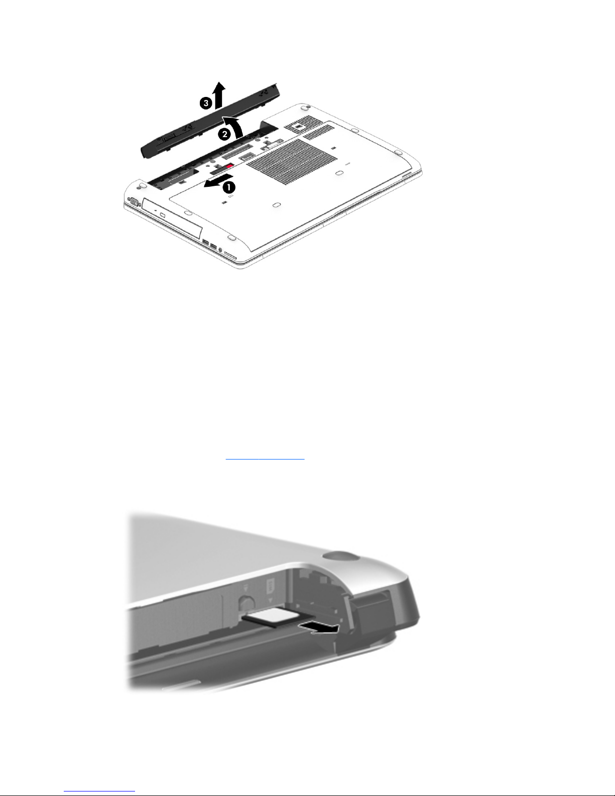
3. Rotate the battery at an angle (2), and then remove the battery from the computer (3).
Install the battery by inserting it into the battery bay until you hear a click.
SIM card
A SIM card slot is located in the battery bay.
Before removing the SIM card, follow these steps:
1. Shut down the computer. If you are unsure whether the computer is off or in Hibernation, turn the
computer on, and then shut it down through the operating system.
2. Disconnect all external devices connected to the computer.
3. Disconnect the power from the computer by first unplugging the power cord from the AC outlet and
then unplugging the AC adapter from the computer.
4. Remove the battery (see Battery on page 45).
Remove the SIM card:
▲
To remove a SIM card, press in on the SIM card, and then remove it from the slot.
Install the SIM card by inserting it into the SIM card slot until you hear a click.
46 Chapter 5 Removal and replacement procedures for Customer Self-Repair parts
Page 59
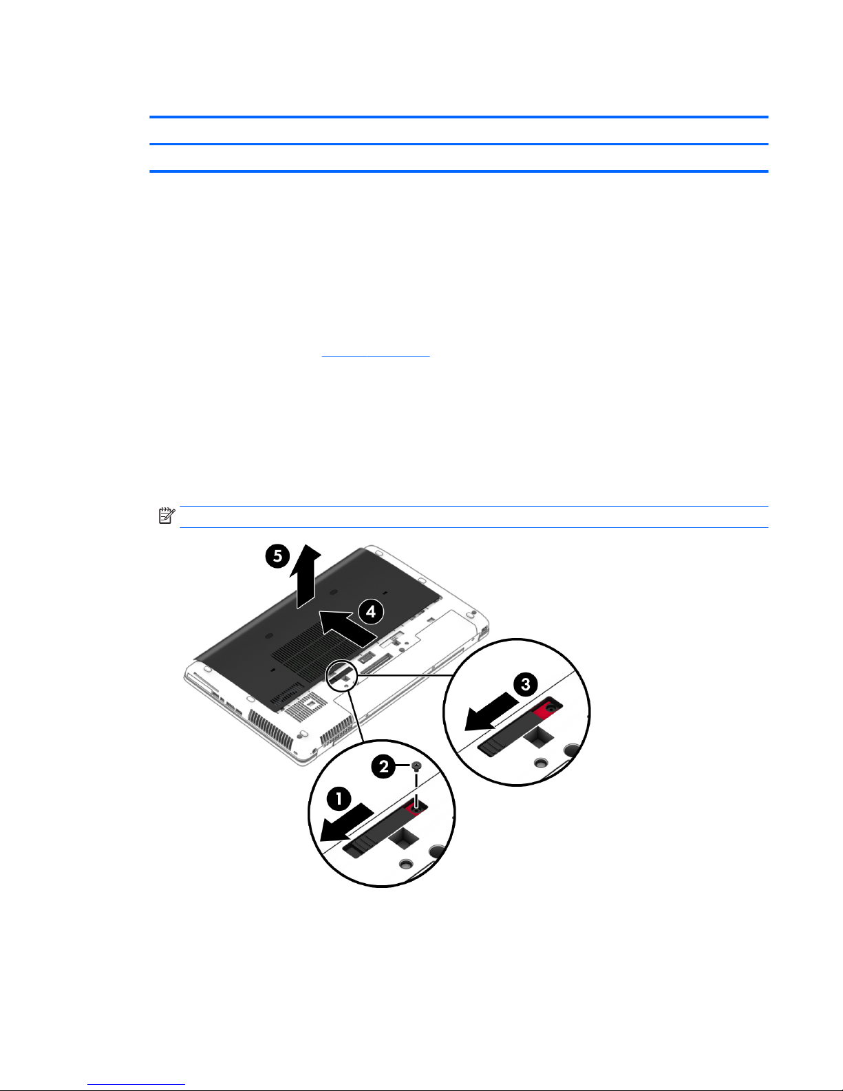
Service cover
Description Spare part number
Service cover 733635-001
Before removing the service cover, follow these steps:
1. Shut down the computer. If you are unsure whether the computer is off or in Hibernation, turn the
computer on, and then shut it down through the operating system.
2. Disconnect all external devices connected to the computer.
3. Disconnect the power from the computer by first unplugging the power cord from the AC outlet and
then unplugging the AC adapter from the computer.
4. Remove the battery (see Battery on page 45).
Remove the service cover:
1. Position the computer upside down on a flat surface with the front toward you.
2. With the battery bay toward you, slide the service cover release latch to the left (1), and then remove
the optional screw (2).
3. Slide the service cover release latch to the left again (3), slide the service cover forward (4), and then lift
to remove the service cover (5).
NOTE: If you do not want to use the optional screw, you can store it inside the service cover.
Reverse this procedure to install the service cover.
Component replacement procedures 47
Page 60
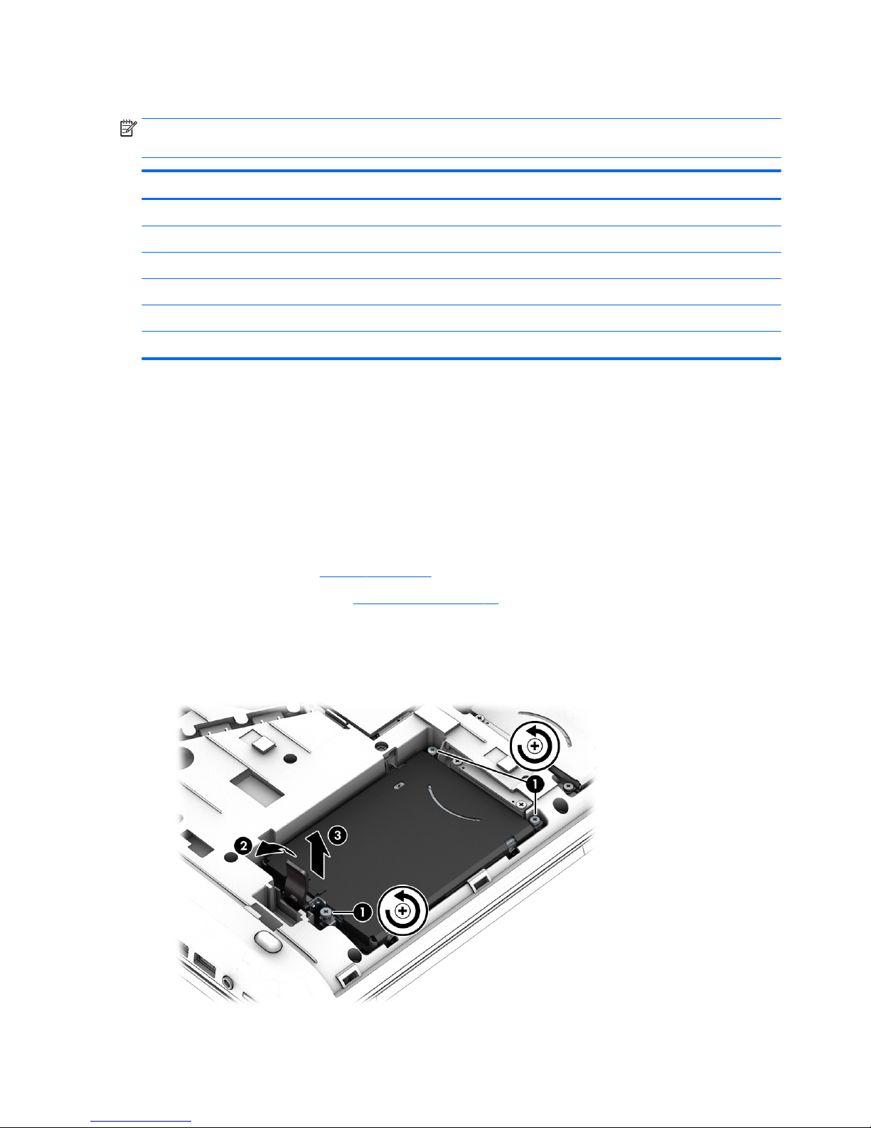
Hard drives, primary and secondary
NOTE: The hard drive spare part kit does not include the hard drive bracket, cover, or screws. The hard drive
bracket, cover, and screws are included in the Hard Drive Hardware Kit, spare part number 734280-001.
Description Spare part number
1-TB, 7200-RPM, SATA, 9.5-mm 766644-001
1-TB, 5400-RPM, SATA, 7.0-mm 778192-001
750-GB, 7200-RPM, SATA, 7.0-mm 778191-001
500-GB, 7200-RPM, SATA, 7.0-mm 703267-001
500-GB, 7200-RPM, SED, 7.0-mm 703268-001
500-GB, 5400-RPM, SATA, FIPS, 7.0-mm 730946-001
Before removing the primary hard drive, follow these steps:
1. Shut down the computer. If you are unsure whether the computer is off or in Hibernation, turn the
computer on, and then shut it down through the operating system.
2. Disconnect all external devices connected to the computer.
3. Disconnect the power from the computer by first unplugging the power cord from the AC outlet and
then unplugging the AC adapter from the computer.
4. Position the computer upside down on a flat surface.
5. Remove the battery (see Battery on page 45).
6. Remove the service cover (see Service cover on page 47).
7. Loosen the 3 captive hard drive screws (1) that secure the hard drive to the computer.
8. Release the hard drive latch (2).
9. Grasp the latch and remove the hard drive (3) from the hard drive bay.
48 Chapter 5 Removal and replacement procedures for Customer Self-Repair parts
Page 61
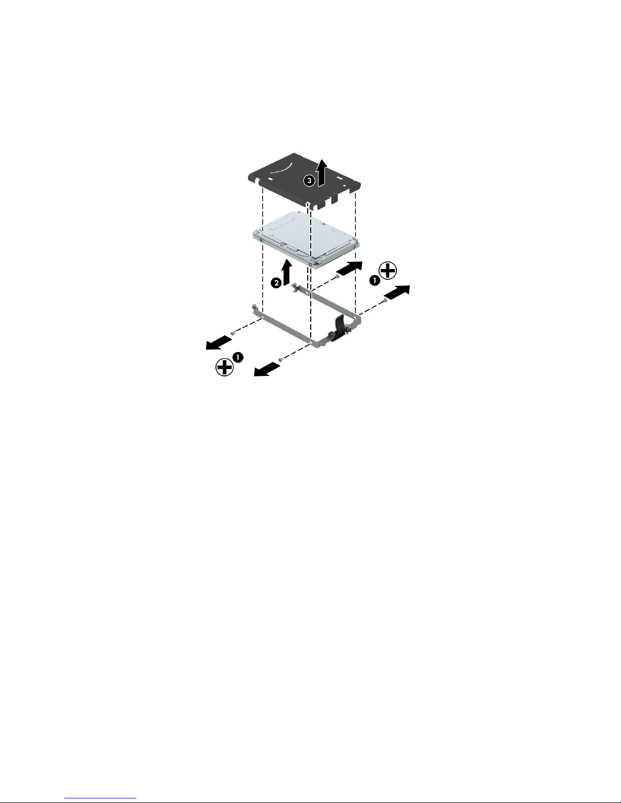
10. If it is necessary to remove the hard drive cover and bracket, follow these steps:
a. Remove the four Phillips M3.0×3.0 screws (1) that secure the hard drive cover and bracket to the
hard drive.
b. Remove the hard drive and cover from the bracket (2).
c. Remove the hard drive cover from the hard drive (3).
Reverse this procedure to reassemble and install the hard drive.
Component replacement procedures 49
Page 62

Solid-state drive
Description Spare part number
512 GB, SATA-3 795969-001
256 GB, SATA-3, SED, Opal2 795968-001
256 GB, SATA-3, SED, Opal1 795967-001
256 GB, SATA-3 795966-001
240 GB, SATA-3 795965-001
180 GB, SATA-3 795964-001
128 GB, SATA-3 795963-001
Before removing the solid-state drive, follow these steps:
1. Shut down the computer. If you are unsure whether the computer is off or in Hibernation, turn the
computer on, and then shut it down through the operating system.
2. Disconnect all external devices connected to the computer.
3. Disconnect the power from the computer by first unplugging the power cord from the AC outlet and
then unplugging the AC adapter from the computer.
4. Remove the battery (see Battery on page 45).
5. Remove the service cover (see Service cover on page 47).
Remove the solid-state drive:
1. Remove the two Phillips PM2.0×3.0 screws (1) that secure the solid-state drive to the computer. (The
solid-state drive tilts up.)
50 Chapter 5 Removal and replacement procedures for Customer Self-Repair parts
Page 63
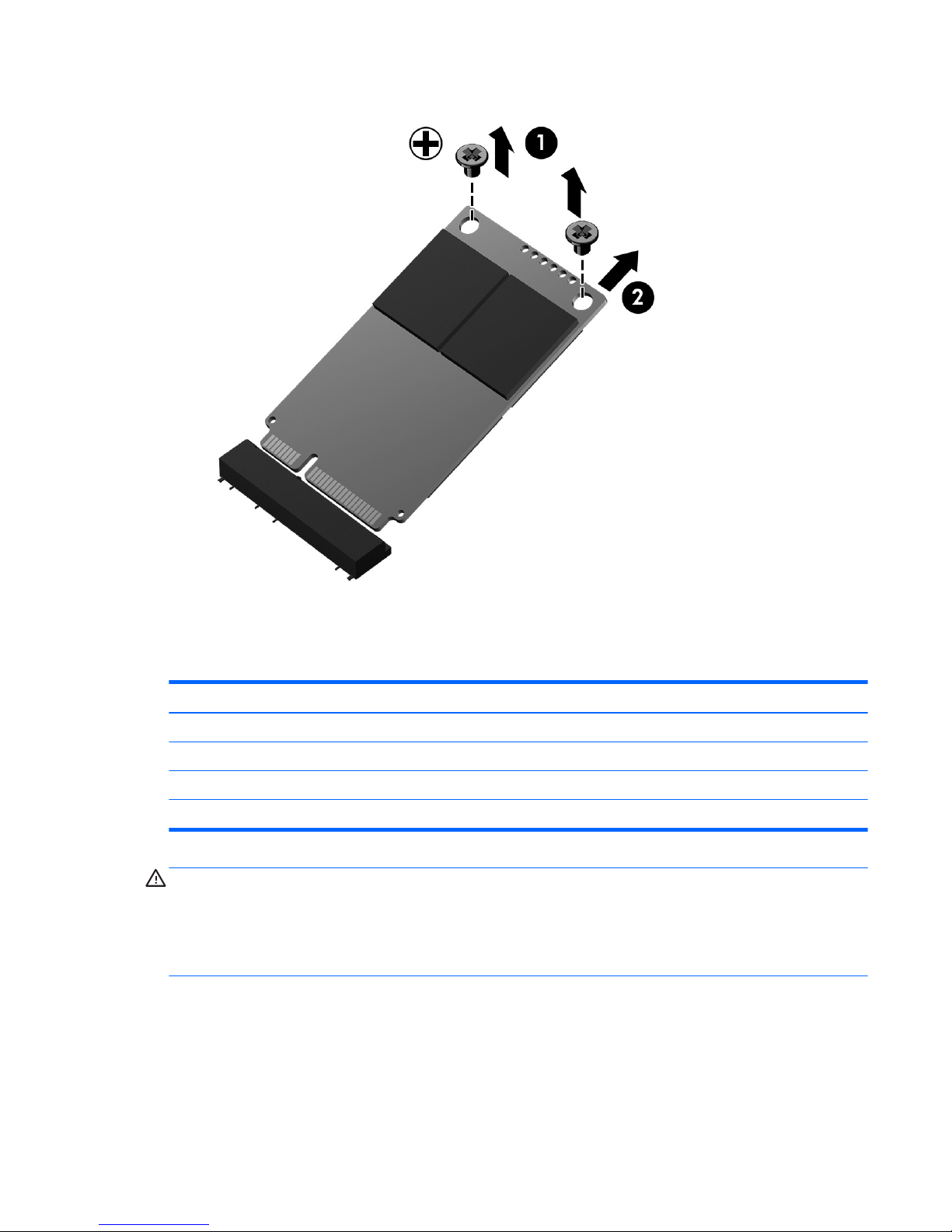
2. Slide the solid-state drive away to remove it from the socket (2).
Reverse this procedure to install the solid-state drive.
WLAN module
Description Spare part number
WLAN Intel Dual Band Wireless-AC 7260 802.11 ac 2×2 WiFi + Bluetooth 4.0 Combo Adapter 710663-001
WLAN Intel Dual Band Wireless-N 7260AN 802.11 a/b/g/n 2×2 WiFi + Bluetooth 4.0 Combo Adapter 717379-001
WLAN Intel Dual Band Wireless-N 7260AN 802.11 a/b/g/n 2×2 WiFi + Bluetooth 4.0 Combo Adapter 747833-001
WLAN Intel Dual Band Wireless-N 7260NB 802.11 a/b/g/n 2×2 WiFi adapter 717380-001
CAUTION: The WLAN module and the WWAN module are not interchangeable.
To prevent an unresponsive system, replace the wireless module only with a wireless module authorized for
use in the computer by the governmental agency that regulates wireless devices in your country or region. If
you replace the module and then receive a warning message, remove the module to restore device
functionality, and then contact technical support.
Before removing the WLAN module, follow these steps:
1. Shut down the computer. If you are unsure whether the computer is off or in Hibernation, turn the
computer on, and then shut it down through the operating system.
2. Disconnect all external devices connected to the computer.
Component replacement procedures 51
Page 64
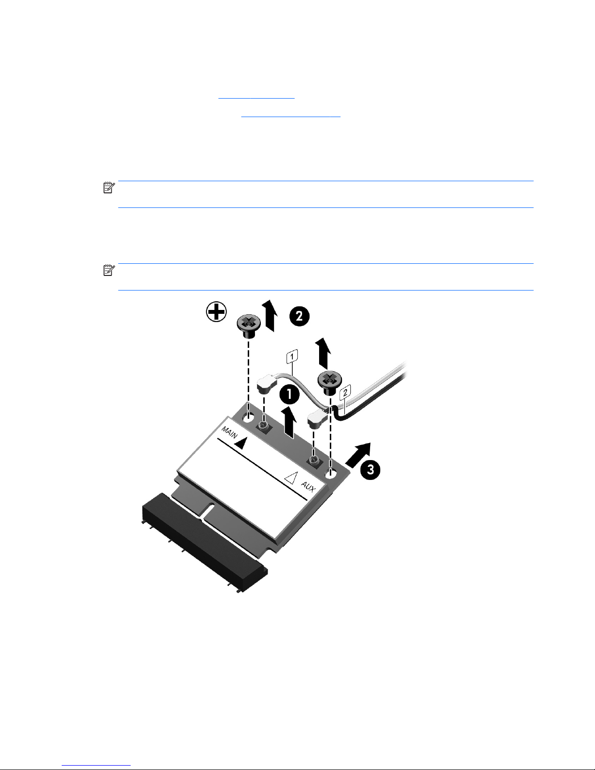
3. Disconnect the power from the computer by first unplugging the power cord from the AC outlet and
then unplugging the AC adapter from the computer.
4. Remove the battery (see Battery on page 45).
5. Remove the service cover (see Service cover on page 47).
Remove the WLAN module:
1. Position the computer with the front toward you.
2. Disconnect the WLAN antenna cables (1) from the terminals on the WLAN module.
NOTE: The WLAN antenna cable labeled “1/Main” connects to the WLAN module “1/Main” terminal.
The WLAN antenna cable labeled “2/Aux” connects to the WLAN module “2/Aux” terminal.
3. Remove the two Phillips PM2.0×3.0 screws (2) that secure the WLAN module to the system board. (The
WLAN module tilts up.)
4. Remove the WLAN module (3) by pulling the module away from the slot at an angle.
NOTE: WLAN modules are designed with a notch to prevent incorrect insertion of the WLAN module
into the WLAN module slot.
Reverse this procedure to install the WLAN module.
52 Chapter 5 Removal and replacement procedures for Customer Self-Repair parts
Page 65

WWAN module
Description Spare part number
HP IT4211 LTE/EV-DO/HSPA+ 4G WWAN module 748021-001
ME906E LT4112 LTE/HPSA+ WWAN module 740011-001
MU736 HS3110 GEN HSPA+ M.2 WWAN module 748599-001
CAUTION: The WWAN module and the WLAN module are not interchangeable.
To prevent an unresponsive system, replace the wireless module only with a wireless module authorized for
use in the computer by the governmental agency that regulates wireless devices in your country or region. If
you replace the module and then receive a warning message, remove the module to restore device
functionality, and then contact technical support.
Before removing the WWAN module, follow these steps:
1. Shut down the computer. If you are unsure whether the computer is off or in Hibernation, turn the
computer on, and then shut it down through the operating system.
2. Disconnect all external devices connected to the computer.
3. Disconnect the power from the computer by first unplugging the power cord from the AC outlet and
then unplugging the AC adapter from the computer.
4. Remove the battery (see Battery on page 45).
5. Remove the service cover (see Service cover on page 47).
Remove the WWAN module:
1. Disconnect the WWAN antenna cables (1) from the terminals on the WWAN module.
NOTE: The red WWAN antenna cable connects to the WWAN module “5/Main” terminal. The blue
WWAN antenna cable connects to the WWAN module “6/Aux” terminal.
2. Remove the Phillips PM2.0×3.0 screw (2) that secures the WWAN module to the system board. (The
WWAN module tilts up.)
Component replacement procedures 53
Page 66
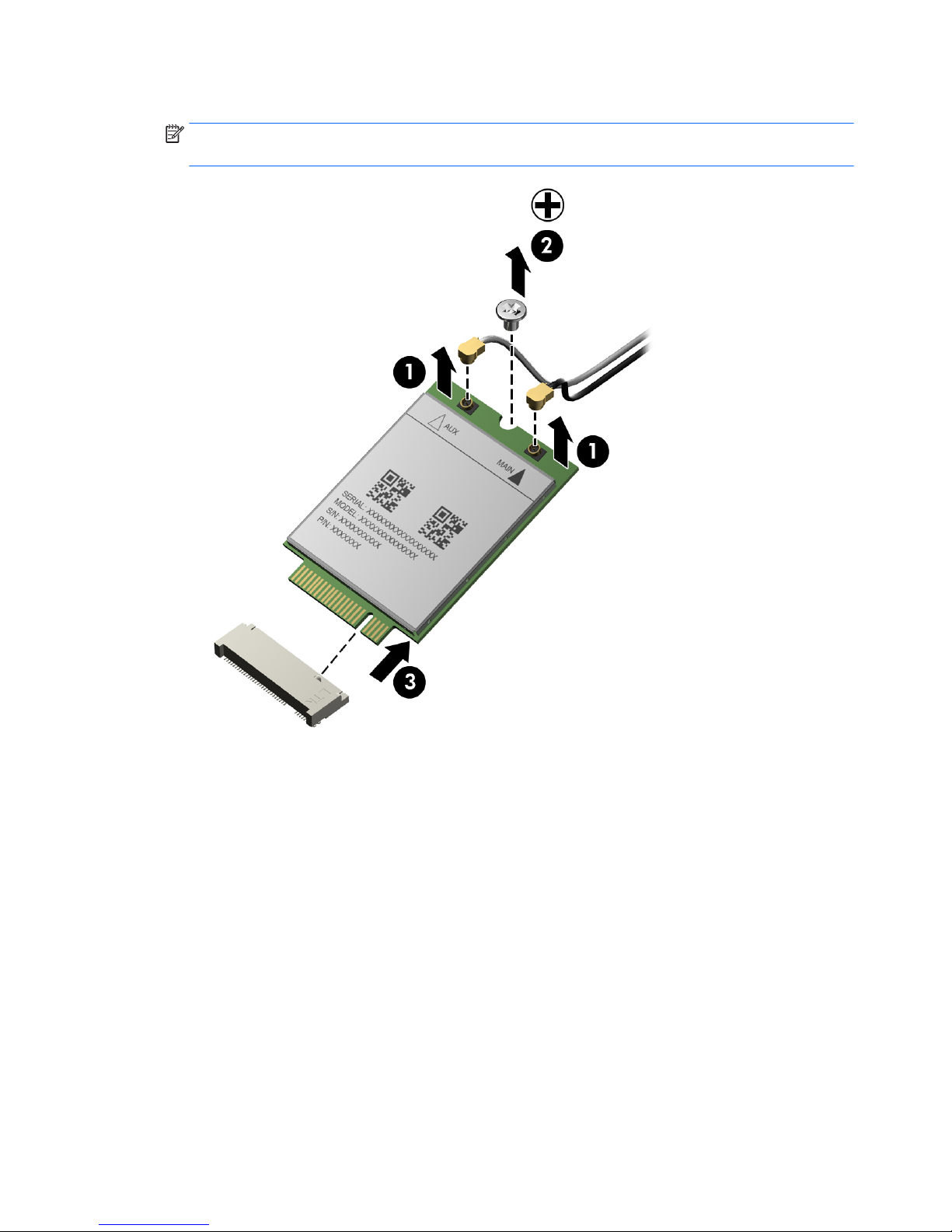
3. Remove the WWAN module (3) by pulling the module away from the slot at an angle.
NOTE: WWAN modules are designed with a notch to prevent incorrect insertion of the WWAN module
into the WWAN module slot.
Reverse this procedure to install the WWAN module.
54 Chapter 5 Removal and replacement procedures for Customer Self-Repair parts
Page 67
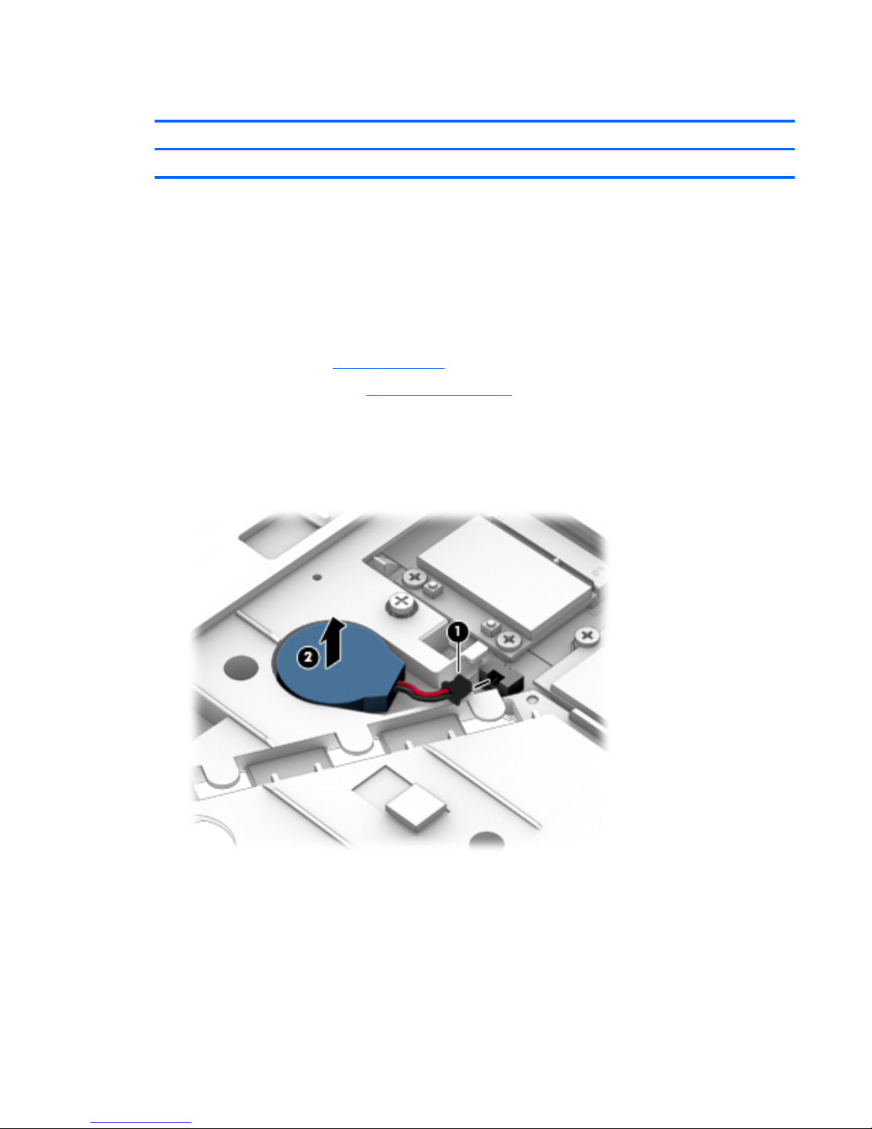
RTC battery
Description Spare part number
RTC battery (includes cable and double-sided adhesive) 734300-001
Before removing the RTC battery, follow these steps:
1. Shut down the computer. If you are unsure whether the computer is off or in Hibernation, turn the
computer on, and then shut it down through the operating system.
2. Disconnect all external devices connected to the computer.
3. Disconnect the power from the computer by first unplugging the power cord from the AC outlet and
then unplugging the AC adapter from the computer.
4. Remove the battery (see Battery on page 45).
5. Remove the service cover (see Service cover on page 47).
Remove the RTC battery:
1. Disconnect the RTC battery cable (1) from the system board.
2. Detach the RTC battery (2) from the base enclosure. (The RTC battery is attached to the base enclosure
with double-sided adhesive.)
3. Remove the RTC battery.
Reverse this procedure to install the RTC battery.
Component replacement procedures 55
Page 68

Optical drive
NOTE: The Upgrade Bay supports both optical drives and hard drives. If you switch from a hard drive to an
optical drive in the Upgrade Bay, you will need to remove four additional screws that secure the hard drive
carrier.
NOTE: All optical drive spare part kits include bezel, bracket, and screws.
Description Spare part number
Blu-ray R/RE DVD±RW SuperMulti Double-Layer Drive 735600-001
Blu-ray ROM DVD±RW SuperMulti Double-Layer Drive 735599-001
DVD±RW SuperMulti Double-Layer Drive 735602-001
Before removing the optical drive, follow these steps:
1. Shut down the computer. If you are unsure whether the computer is off or in Hibernation, turn the
computer on, and then shut it down through the operating system.
2. Disconnect all external devices connected to the computer.
3. Disconnect the power from the computer by first unplugging the power cord from the AC outlet and
then unplugging the AC adapter from the computer.
4. Remove the battery (see Battery on page 45).
5. Remove the service cover (see Service cover on page 47).
Remove the optical drive:
1. Position the computer with the front toward you.
2. Loosen the Phillips captive screw (1) that secures the optical drive to the computer.
3. Insert a flat-bladed screwdriver or similar tool into the optical drive tab access (2) and press the tab to
the left to release the optical drive from the computer.
56 Chapter 5 Removal and replacement procedures for Customer Self-Repair parts
Page 69
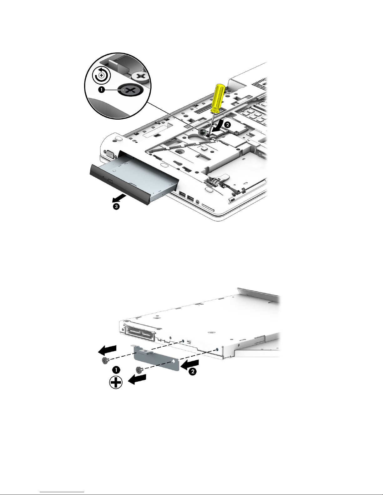
4. Remove the optical drive (3).
5. If it is necessary to replace the optical drive bracket:
a. Position the optical drive with the rear toward you.
b. Remove the two Phillips M2.0×3.0 screws (1) that secure the optical drive bracket to the optical
drive.
c. Remove the optical drive bracket (2).
Reverse this procedure to reassemble and install the optical drive.
Component replacement procedures 57
Page 70
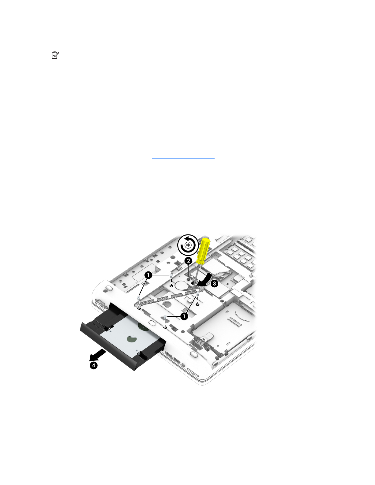
Upgrade Bay hard drive
NOTE: The Upgrade Bay hard drive must be installed in the Upgrade Bay hard drive carrier before it can be
installed in the computer. The Upgrade Bay hard drive carrier is available using spare part number
734298-001.
Before removing the Upgrade Bay hard drive, follow these steps:
1. Shut down the computer. If you are unsure whether the computer is off or in Hibernation, turn the
computer on, and then shut it down through the operating system.
2. Disconnect all external devices connected to the computer.
3. Disconnect the power from the computer by first unplugging the power cord from the AC outlet and
then unplugging the AC adapter from the computer.
4. Remove the battery (see Battery on page 45).
5. Remove the service cover (see Service cover on page 47).
Remove the Upgrade Bay hard drive:
1. Position the computer with the front toward you.
2. Remove the four Phillips PM3.0×5.0 screws (1) that secure the Upgrade Bay hard drive carrier to the
computer.
3. Loosen the captive Phillips screw (2) that secures the Upgrade Bay hard drive carrier to the computer,
and then insert a flat-bladed screwdriver or similar tool into the Upgrade Bay hard drive tab access (3)
and press the tab to the left to release the Upgrade Bay hard drive carrier from the computer (4).
58 Chapter 5 Removal and replacement procedures for Customer Self-Repair parts
Page 71
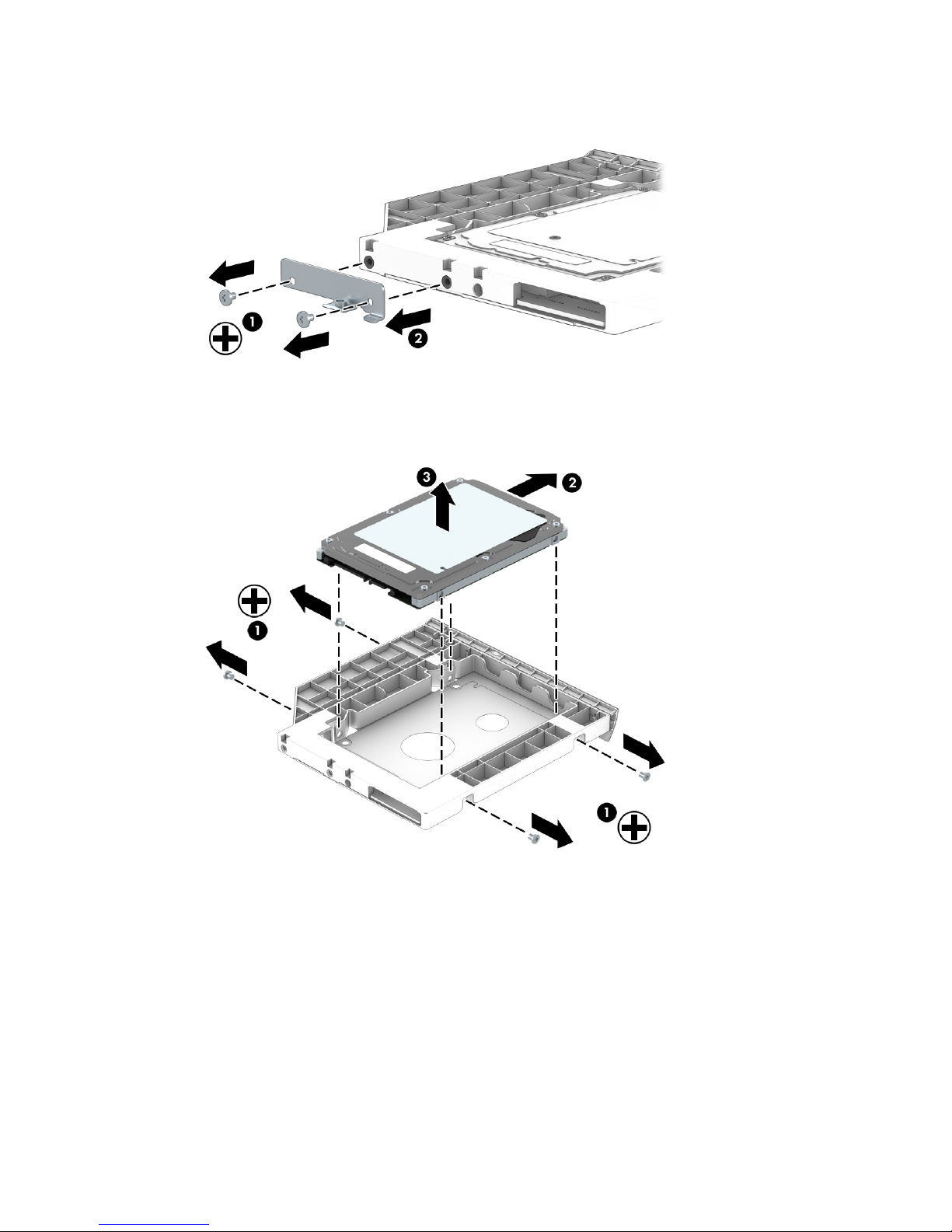
4. Remove the two Phillips PM2.0×5.0 screws (1) that secure the top bracket to the hard drive carrier, and
then remove the bracket from the carrier (2).
5. Remove the four Phillips PM2.5×3.0 screws (1) that secure the hard drive to the carrier, and then pull
the hard drive away from the connector (2) to disengage it.
6. Remove the hard drive (3).
Reverse this procedure to reassemble and install the Upgrade Bay hard drive and Upgrade Bay hard drive
carrier.
Component replacement procedures 59
Page 72
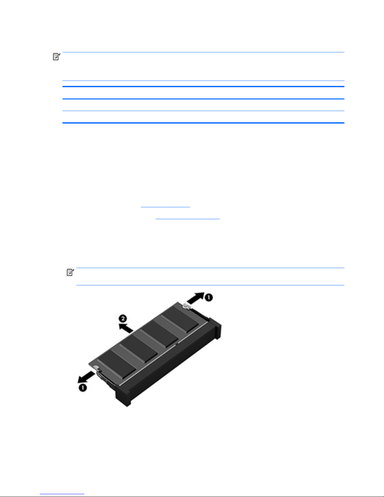
Expansion memory module
NOTE: The computer has four memory slots. Expansion memory slots are located in a compartment on the
bottom of the computer. Primary memory slots are located under the keyboard.
When you add or replace memory modules, slot 1 must be populated before slot 2 is populated.
Description Spare part number
8.0-MB memory module (PC3L-12800, 1600 MHz, DDR3L) 693374-001
4.0-MB memory module (PC3L-12800, 1600 MHz, DDR3L) 691740-001
Before removing an expansion memory module, follow these steps:
1. Shut down the computer. If you are unsure whether the computer is off or in Hibernation, turn the
computer on, and then shut it down through the operating system.
2. Disconnect all external devices connected to the computer.
3. Disconnect the power from the computer by first unplugging the power cord from the AC outlet and
then unplugging the AC adapter from the computer.
4. Remove the battery (see Battery on page 45).
5. Remove the service cover (see Service cover on page 47).
Remove an expansion memory module:
1. Spread the retention tabs (1) on each side of the expansion memory module slot to release the
expansion memory module. (The edge of the module opposite the slot rises away from the computer.)
2. Remove the expansion memory module (2) by pulling the module away from the slot at an angle.
NOTE: Memory modules are designed with a notch to prevent incorrect installation into the expansion
memory module slots.
Reverse this procedure to install an expansion memory module.
60 Chapter 5 Removal and replacement procedures for Customer Self-Repair parts
Page 73

Keyboard
NOTE: The keyboard spare part kit includes a backlight and cable, pointing stick and cable, TouchPad and
cable, and the keyboard cable.
For use in country or region Spare part number For use in country or region Spare part number
For use in Belgium 733688-A41 For use in Northwest Africa 733688-FP1
For use in Brazil 733688-201 For use in Norway 733688-091
For use in Bulgaria 733688-261 For use in Portugal 733688-131
For use in Canada 733688-DB1 For use in Romania 733688-271
For use in the Czech Republic and Slovakia 733688-FL1 For use in Russia 733688-251
For use in Denmark 733688-081 For use in Saudi Arabia 733688-171
For use in France 733688-051 For use in Slovenia 733688-BA1
For use in Germany 733688-041 For use in South Korea 733688-AD1
For use in Greece 733688-151 For use in Spain 733688-071
For use in Hungary 733688-211 For use in Sweden and Finland 733688-B71
For use in Iceland 733688-DD1 For use in Switzerland 733688-BG1
For use in India 733688-D61 For use in Taiwan 733688-AB1
For use in Israel 733688-BB1 For use in Thailand 733688-281
For use in Italy 733688-061 For use in Turkey 733688-141
For use in Japan 733688-291 For use in the United Kingdom
and Singapore
733688-031
For use in Latin America 733688-161 For use in the United States 733688-001
For use in the Netherlands 733688-B31
Before removing the keyboard, follow these steps:
1. Shut down the computer. If you are unsure whether the computer is off or in Hibernation, turn the
computer on, and then shut it down through the operating system.
2. Disconnect all external devices connected to the computer.
3. Disconnect the power from the computer by first unplugging the power cord from the AC outlet and
then unplugging the AC adapter from the computer.
4. Remove the battery (see Battery on page 45).
5. Remove the service cover (see Service cover on page 47).
6. Remove the optical drive (see Optical drive on page 56) or Upgrade Bay hard drive (see Upgrade Bay
hard drive on page 58).
Remove the keyboard:
1. Turn the computer upside down the front toward you.
Component replacement procedures 61
Page 74
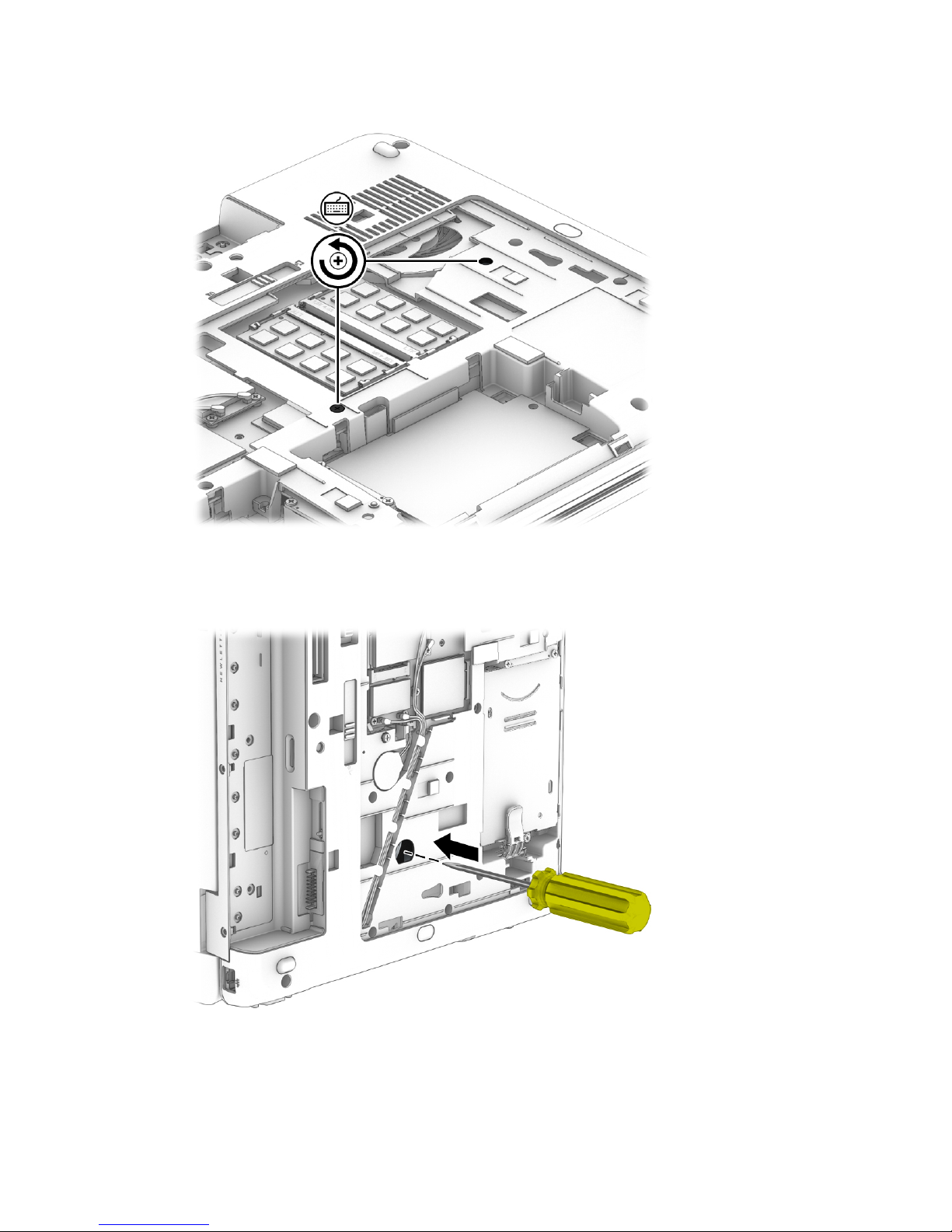
2. Loosen the two Phillips captive screws that secure the keyboard to the computer.
3. Position the computer on its side with the display open at a 90-degree angle.
4. Insert a screw driver or similar thin tool into the keyboard release opening in the optical drive bay, and
then press on the back of the keyboard until the keyboard disengages from the computer.
5. Turn the computer right side up with the front toward you.
6. Open the computer as far as it will open.
62 Chapter 5 Removal and replacement procedures for Customer Self-Repair parts
Page 75
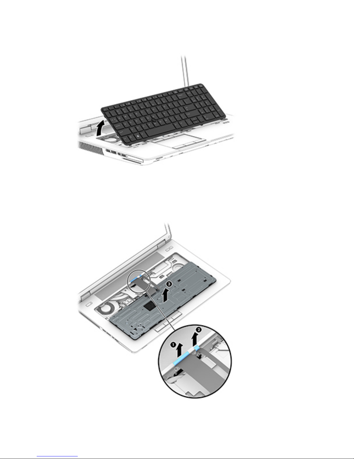
7. Lift the rear edge of the keyboard, and then swing it up and forward until it rests upside down on the
palm rest.
8. Release the zero insertion force (ZIF) connector (1) to which the keyboard cable is attached, and then
disconnect the keyboard cable from the system board.
9. Release the ZIF connector (2) to which the pointing stick cable is attached, and then disconnect the
pointing stick cable (2) from the system board.
10. Remove the keyboard (3).
Reverse this procedure to install the keyboard.
Component replacement procedures 63
Page 76
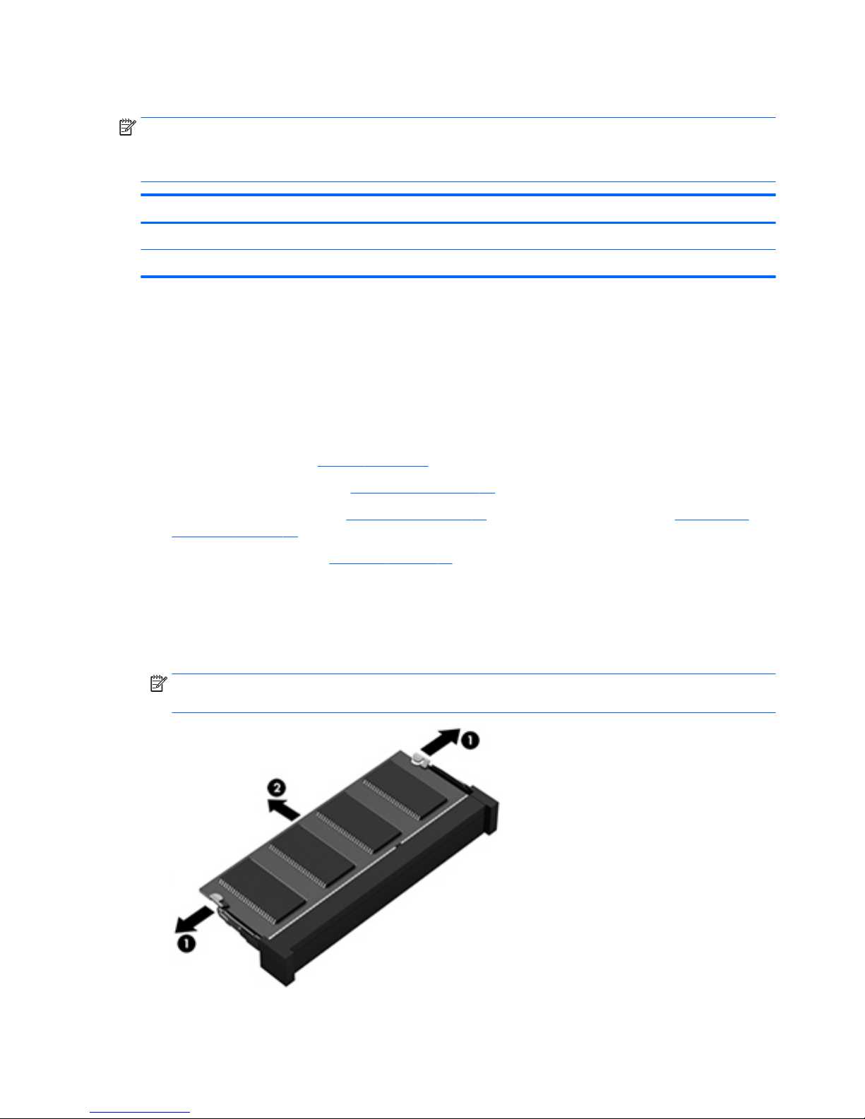
Primary memory module
NOTE: The computer has four memory slots. Expansion memory slots are located in a compartment on the
bottom of the computer. Primary memory slots are located under the keyboard.
When you add or replace the primary memory modules, populate the bottom slot before the top slot.
Description Spare part number
8.0-MB memory module (PC3L-12800, 1600 MHz, DDR3L) 693374-001
4.0-MB memory module (PC3L-12800, 1600 MHz, DDR3L) 691740-001
Before removing a primary memory module, follow these steps:
1. Shut down the computer. If you are unsure whether the computer is off or in Hibernation, turn the
computer on, and then shut it down through the operating system.
2. Disconnect all external devices connected to the computer.
3. Disconnect the power from the computer by first unplugging the power cord from the AC outlet and
then unplugging the AC adapter from the computer.
4. Remove the battery (see Battery on page 45).
5. Remove the service cover (see Service cover on page 47)
6. Remove the optical drive (see Optical drive on page 56) or Upgrade Bay hard drive (see Upgrade Bay
hard drive on page 58).
7. Remove the keyboard (see Keyboard on page 61).
Remove the primary memory module:
1. Spread the retetntion tabs (1) on each side of the primary memory module slot to release the primary
memory module. (The edge of the module opposite the slot rises away from the computer.)
2. Remove the primary memory module (2) by pulling the module away from the slot at an angle.
NOTE: Memory modules are designed with a notch to prevent incorrect installation into the primary
memory module slots.
64 Chapter 5 Removal and replacement procedures for Customer Self-Repair parts
Page 77

Reverse this procedure to install a primary memory module.
Component replacement procedures 65
Page 78

6 Removal and replacement procedures for
Authorized Service Provider parts
CAUTION: Components described in this chapter should only be accessed by an authorized service provider.
Accessing these parts can damage the computer or void the warranty.
Component replacement procedures
This chapter provides removal and replacement procedures for Authorized Service Provider only parts.
There are as many as 91 screws that must be removed, replaced, or loosened when servicing Authorized
Service Provider only parts. Make special note of each screw size and location during removal and
replacement.
Display bezel
NOTE: The display bezel, webcam/microphone module, microphone module, and display panel can be
removed without removing the display assembly from the computer.
Description Spare part number
For use only on computer models equipped with a webcam 733633-001
For use only on computer models not equipped a webcam 735589-001
Before removing the display bezel, follow these steps:
1. Shut down the computer. If you are unsure whether the computer is off or in Hibernation, turn the
computer on, and then shut it down through the operating system.
2. Disconnect all external devices connected to the computer.
3. Disconnect the power from the computer by first unplugging the power cord from the AC outlet and
then unplugging the AC adapter from the computer.
4. Remove the battery (see Battery on page 45).
Remove the display bezel:
1. Turn the computer right side up with the front toward you.
2. Open the computer as far as it will open.
66 Chapter 6 Removal and replacement procedures for Authorized Service Provider parts
Page 79
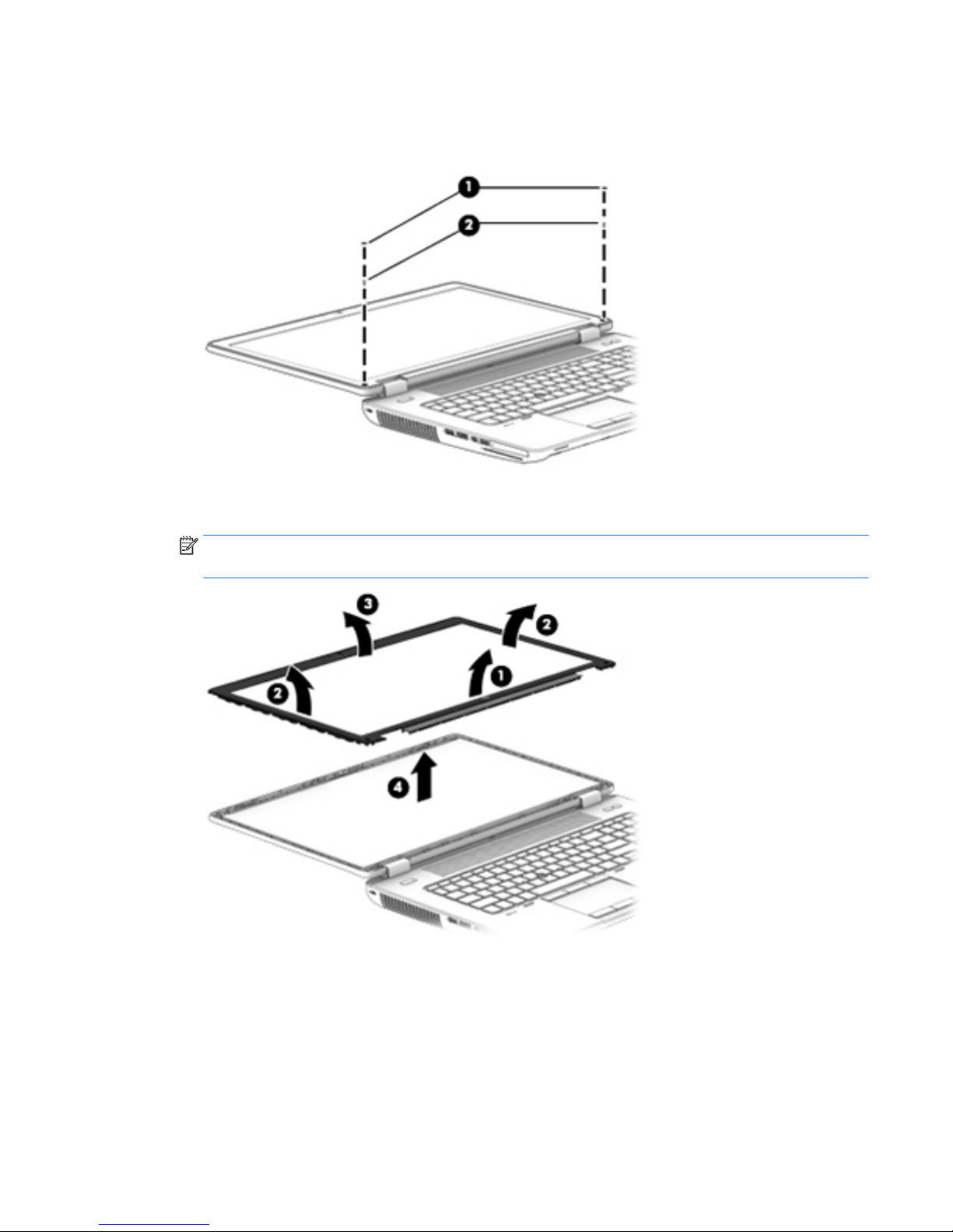
3. Remove the screw covers (1) and the two Phillips PM2.0x7.0 screws (2) that secure the display bezel to
the display enclosure.
The screw covers are available in the Display Panel Support Kit, spare part number 784211-001.
4. Flex the inside edges of the bottom edge (1), the left and right sides (2), and the top edge (3) of the
display bezel until the bezel disengages from the display enclosure and then remove the bezel (4).
NOTE: The top edge of the display bezel contains double-sided adhesive. Additional pressure may be
needed to detach the top edge of the display bezel from the display enclosure.
Reverse this procedure to install the display bezel.
Component replacement procedures 67
Page 80
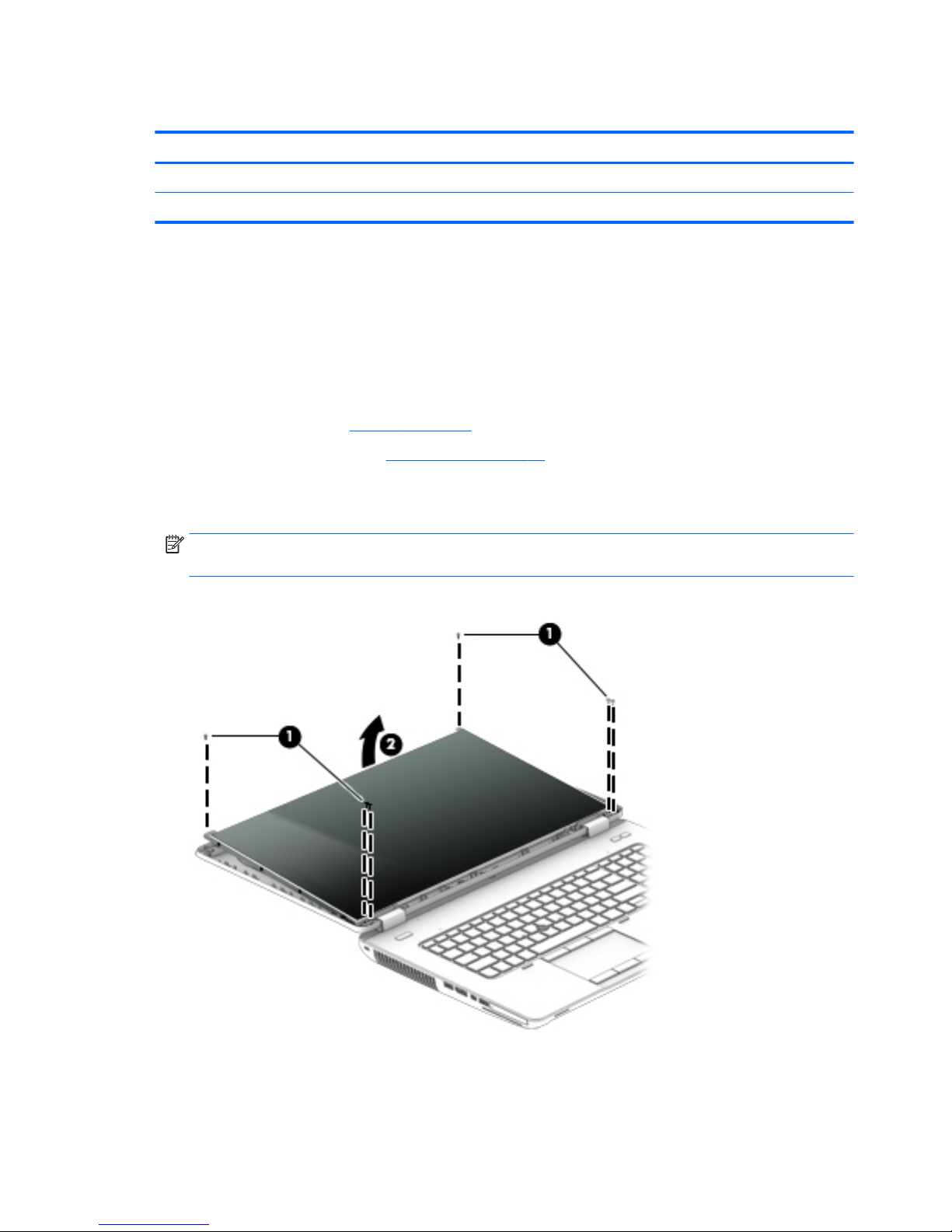
Display panel
Description Spare part number
17.3-in, FHD, AG, LED, WVA display panel 735367-001
17.3-in, HD, AG, LED, WVA display panel 735366-001
Before removing the display panel, follow these steps:
1. Shut down the computer. If you are unsure whether the computer is off or in Hibernation, turn the
computer on, and then shut it down through the operating system.
2. Disconnect all external devices connected to the computer.
3. Disconnect the power from the computer by first unplugging the power cord from the AC outlet and
then unplugging the AC adapter from the computer.
4. Remove the battery (see Battery on page 45).
5. Remove the display bezel (see Display bezel on page 66).
Remove the display panel:
1. Release the top edge of the display panel from the display enclosure (1).
NOTE: If grounding tape secures the top edge of the display panel to the display enclosure, release
the tape to disengage the panel from the enclosure.
2. Remove the six Torx T8M2.5×7.0 screws (2) that secure the display panel to the display enclosure.
68 Chapter 6 Removal and replacement procedures for Authorized Service Provider parts
Page 81
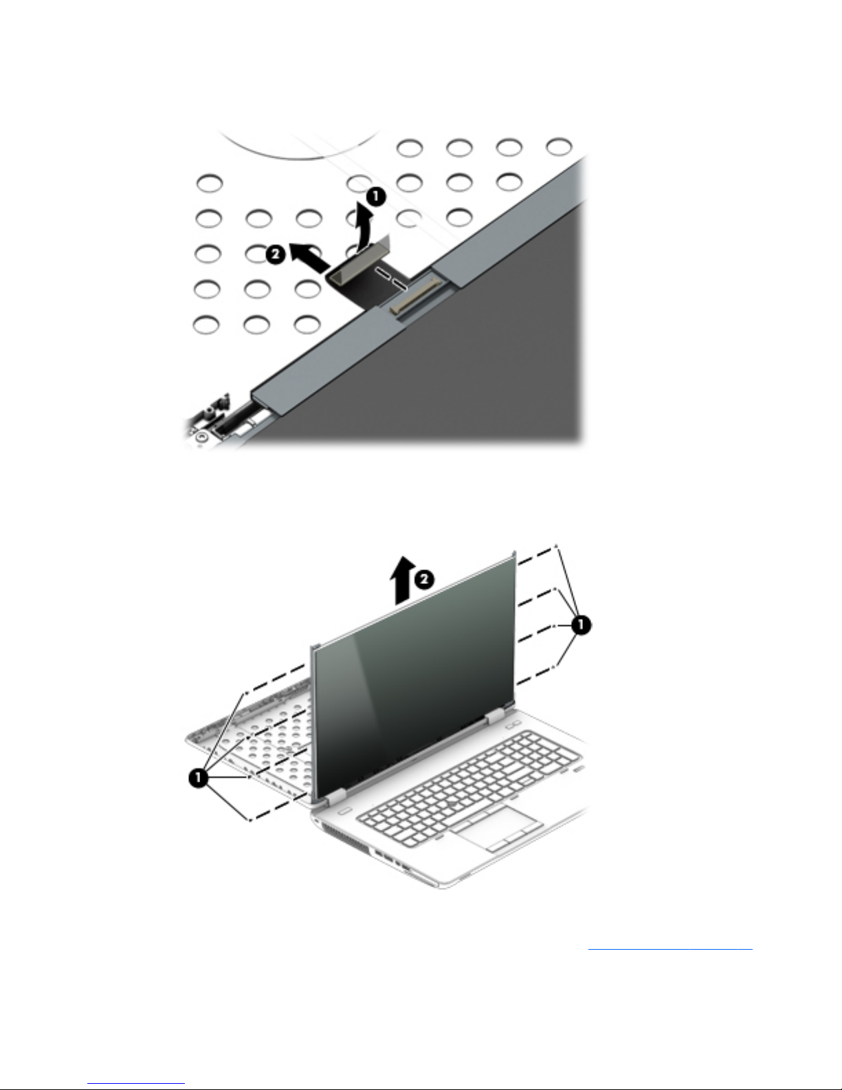
3. Lift the tape that covers the connector on the back of display panel (1), and then disconnect the display
panel cable (2).
4. Remove the eight Phillips PM2.0×3.0 screws (1) that secure the display panel to the display hinge
brackets.
5. Slide the display panel up and out of the display hinge brackets (2).
To replace the remaining display assembly components, remove the display assembly from the computer.
Reverse this procedure to install the display panel. For more information, see Display assembly on page 81.
Component replacement procedures 69
Page 82
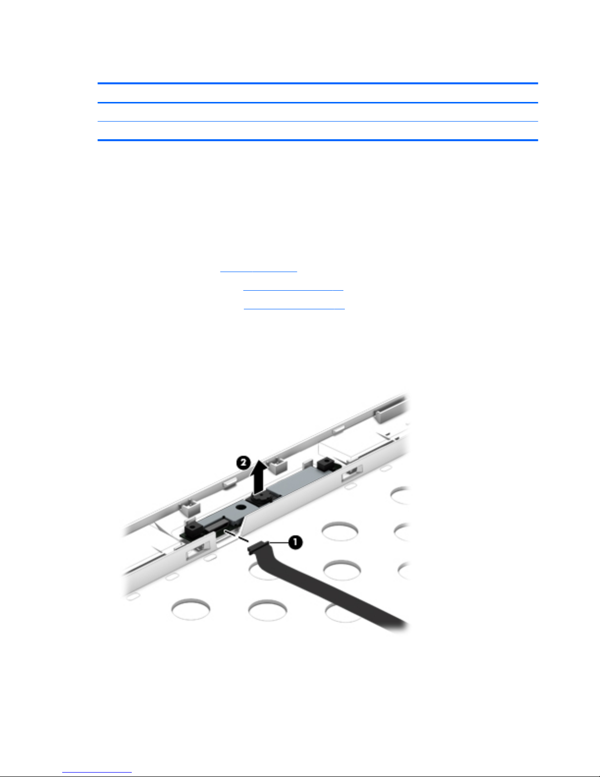
Webcam/microphone module
Description Spare part number
Webcam/microphone module (includes double-sided adhesive) 784208-001
Microphone module (includes double-sided adhesive) 735370-001
Before removing the webcam/microphone module, follow these steps:
1. Shut down the computer. If you are unsure whether the computer is off or in Hibernation, turn the
computer on, and then shut it down through the operating system.
2. Disconnect all external devices connected to the computer.
3. Disconnect the power from the computer by first unplugging the power cord from the AC outlet and
then unplugging the AC adapter from the computer.
4. Remove the battery (see Battery on page 45).
5. Remove the display bezel (see Display bezel on page 66).
6. Remove the display panel (see Display panel on page 68).
Remove the webcam/microphone module:
1. Disconnect the cable from the webcam/microphone module (1).
2. Detach the webcam/microphone module (2) from the display enclosure. (The webcam/microphone
module is attached to the display enclosure with double-sided tape.)
Reverse this procedure to install the webcam/microphone module.
70 Chapter 6 Removal and replacement procedures for Authorized Service Provider parts
Page 83

Top cover
Description Spare part number
Top cover 735587-001
Before removing the top cover, follow these steps:
1. Shut down the computer. If you are unsure whether the computer is off or in Hibernation, turn the
computer on, and then shut it down through the operating system.
2. Disconnect all external devices connected to the computer.
3. Disconnect the power from the computer by first unplugging the power cord from the AC outlet and
then unplugging the AC adapter from the computer.
4. Remove the battery (see Battery on page 45).
5. Remove the service cover (see Service cover on page 47).
6. Remove the optical drive (see Optical drive on page 56) or upgrade bay hard drive (see Upgrade Bay
hard drive on page 58).
7. Remove the keyboard (see Keyboard on page 61).
NOTE: When replacing the top cover, be sure that the following components are removed from the
defective top cover and installed on the replacement top cover:
●
Multifunction board (see Multifunction board on page 75)
●
Speakers (see Speakers on page 77)
●
Fingerprint reader (see Fingerprint reader on page 78)
●
Power button board (see Power button board on page 79)
Remove the top cover:
1. Close the computer.
2. Turn the computer upside with the front toward you.
Component replacement procedures 71
Page 84
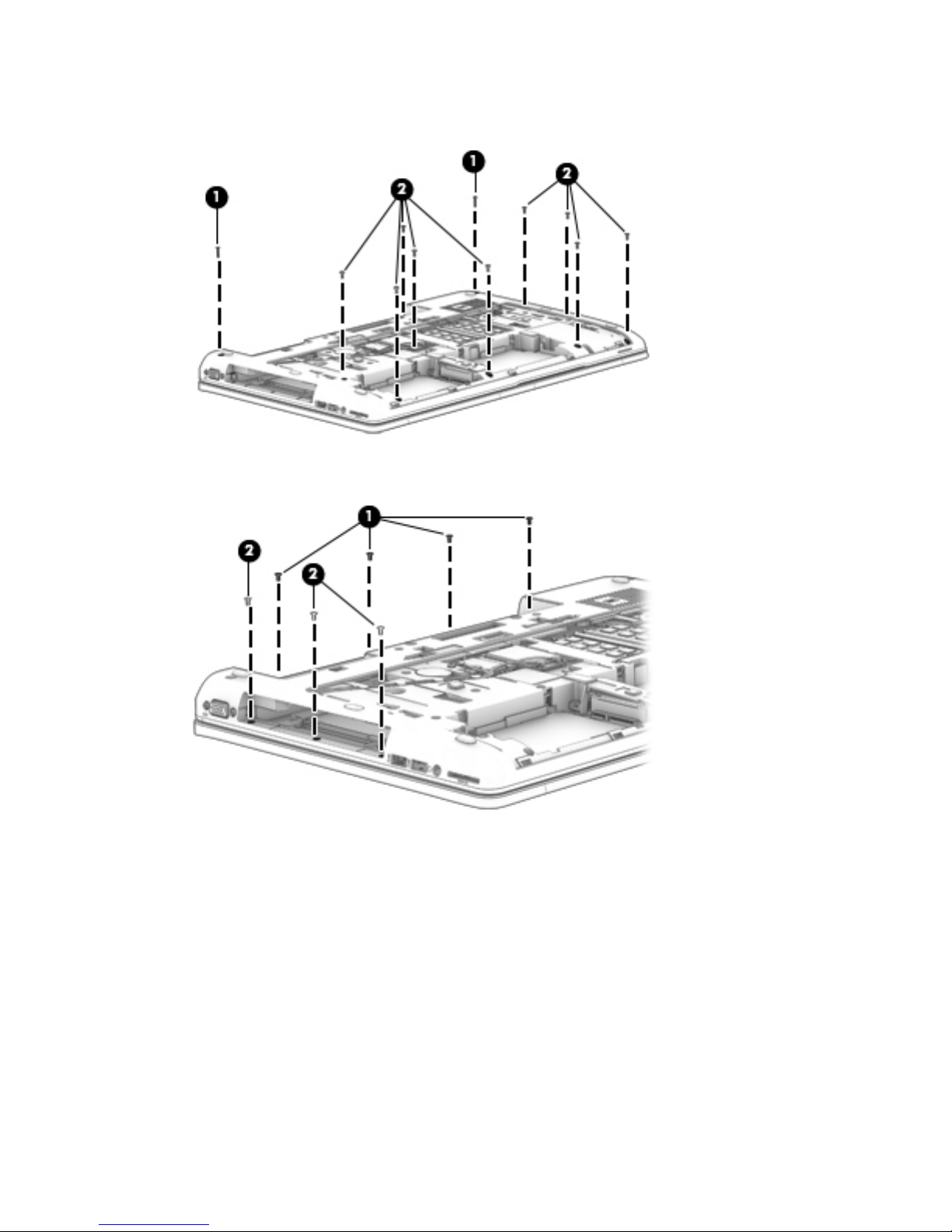
3. Remove the two Torx T8M2.5x11.0 screws (1) and the nine Torx T8M2.5x6.0 screws (2) that secure the
base enclosure to the top cover.
4. Remove the four Torx T8M2.5x5.0 screws inside the battery bay (1) and the three Torx T8M2.5x5.0
screws in the optical drive/upgrade drive bay (2).
5. Turn the computer right side up with the front toward you.
6. Open the computer as far as it will open.
72 Chapter 6 Removal and replacement procedures for Authorized Service Provider parts
Page 85
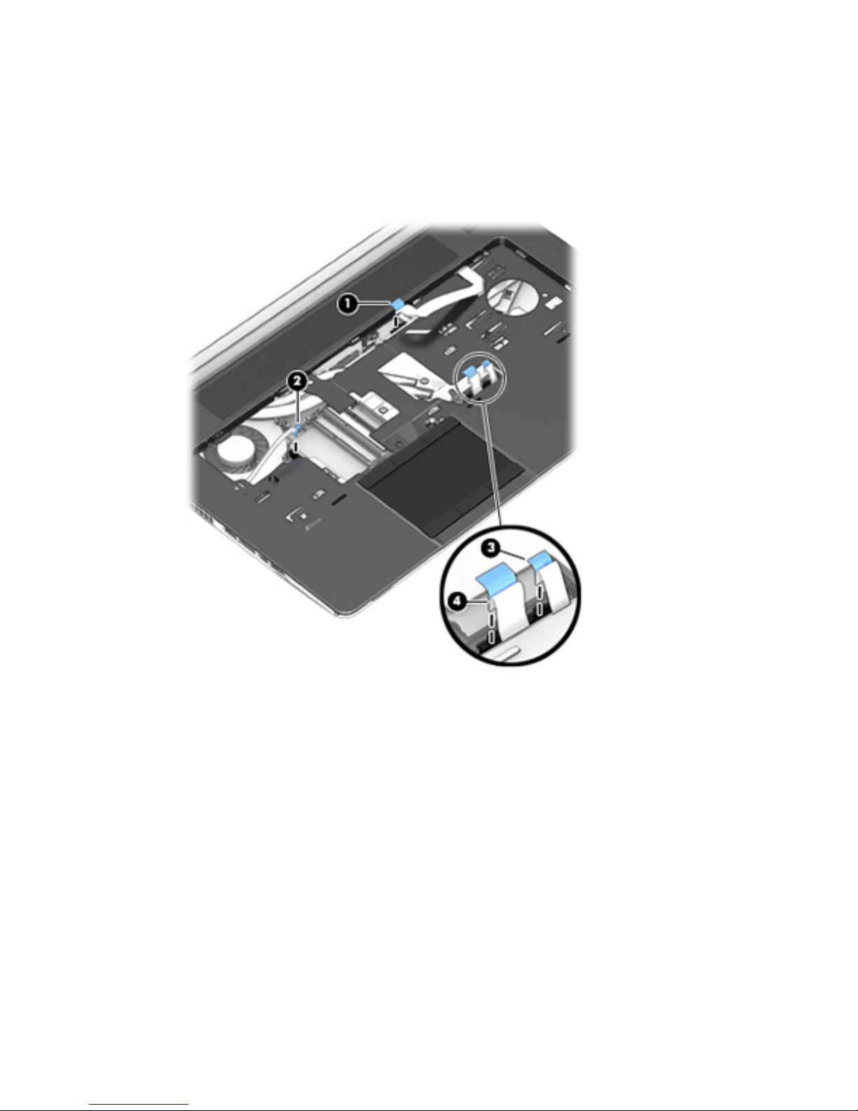
7. Disconnect the following cables:
(1) Function board ZIF connector cable
(2) Power button board ZIF connector cable
(3) TouchPad ZIF connector cable
(4) Fingerprint reader board ZIF connector cable
8. Starting at the top right, release the top cover from the base enclosure (1).
Component replacement procedures 73
Page 86
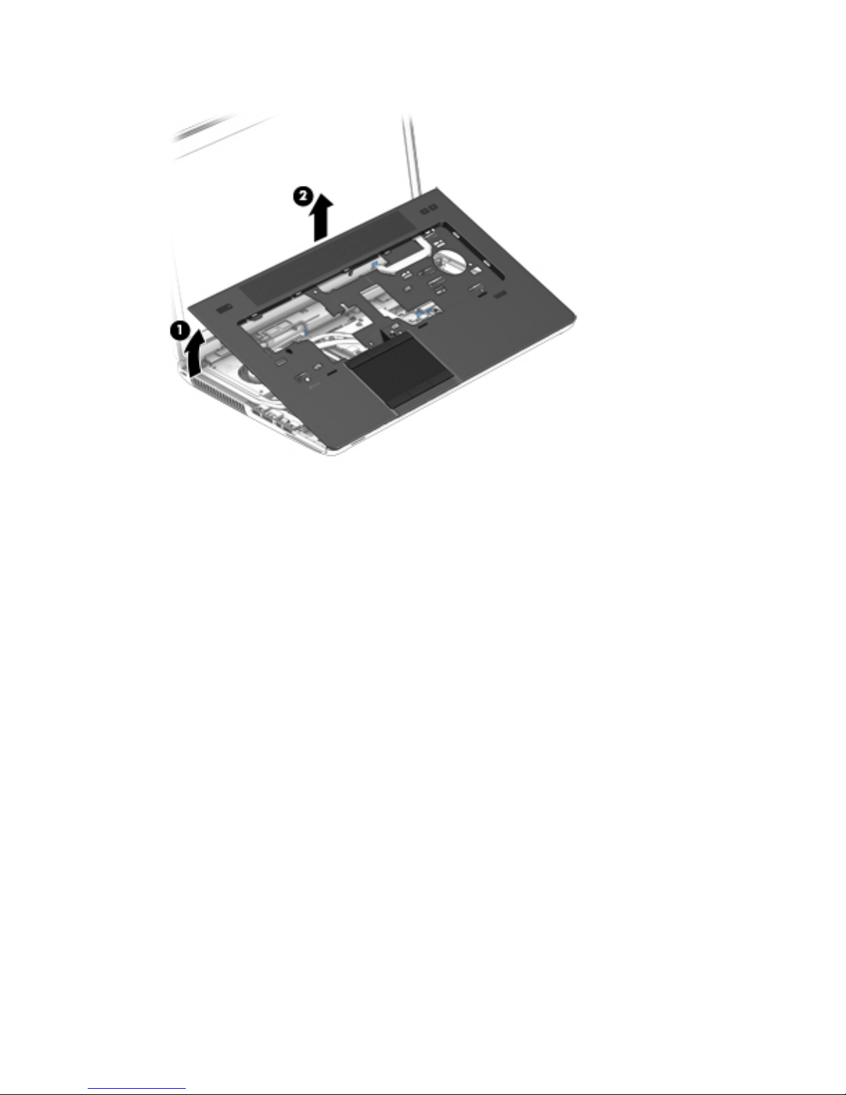
9. Remove the top cover from the base enclosure (2).
Reverse this procedure to install the top cover.
74 Chapter 6 Removal and replacement procedures for Authorized Service Provider parts
Page 87
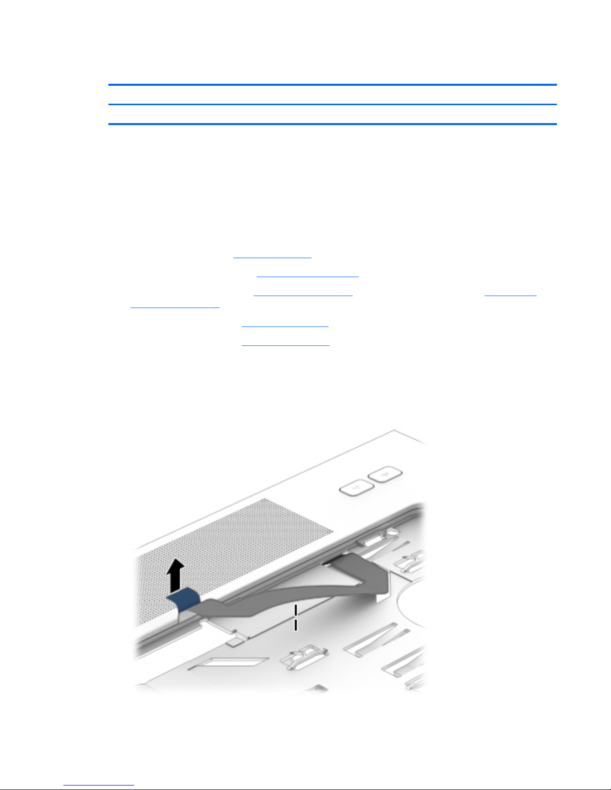
Multifunction board
Description Spare part number
Multifunction board (includes LED light pipe) 733639-001
Before removing the multifunction board, follow these steps:
1. Shut down the computer. If you are unsure whether the computer is off or in Hibernation, turn the
computer on, and then shut it down through the operating system.
2. Disconnect all external devices connected to the computer.
3. Disconnect the power from the computer by first unplugging the power cord from the AC outlet and
then unplugging the AC adapter from the computer.
4. Remove the battery (see Battery on page 45).
5. Remove the service cover (see Service cover on page 47).
6. Remove the optical drive (see Optical drive on page 56) or upgrade bay hard drive (see Upgrade Bay
hard drive on page 58).
7. Remove the keyboard (see Keyboard on page 61).
8. Remove the top cover (see Top cover on page 71).
Remove the multifunction board:
1. Turn the top cover right side up with the front toward you.
2. Detach the multifunction board cable (2) from the top cover. (The multifunction board cable is attached
to the top cover with double-sided tape.)
Component replacement procedures 75
Page 88
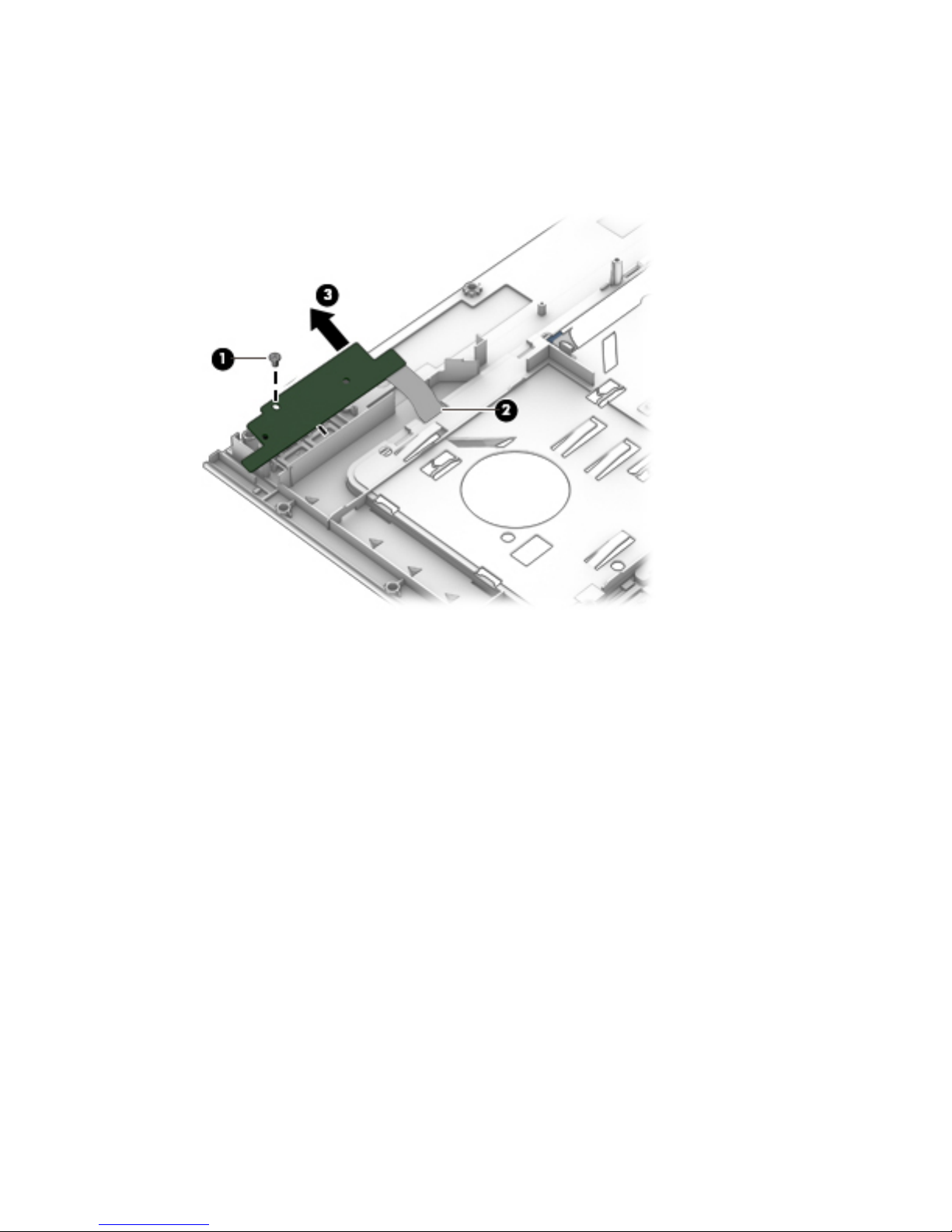
3. Turn the top cover upside down with the front toward you.
4. Remove the Phillips PM2.0×3.0 screw (1) that secures the multifunction board to the top cover.
5. Slide the multifunction board cable through the opening in top cover (2).
6. Remove the multifunction board and cable (3).
Reverse this procedure to install the multifunction board.
76 Chapter 6 Removal and replacement procedures for Authorized Service Provider parts
Page 89
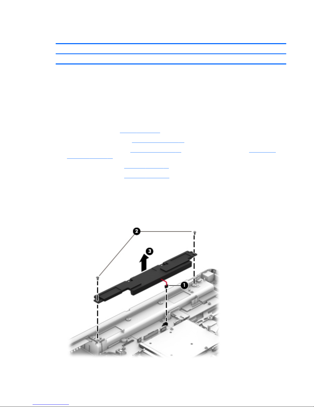
Speakers
Description Spare part number
Speakers 733638-001
Before removing the speaker assembly, follow these steps:
1. Shut down the computer. If you are unsure whether the computer is off or in Hibernation, turn the
computer on, and then shut it down through the operating system.
2. Disconnect all external devices connected to the computer.
3. Disconnect the power from the computer by first unplugging the power cord from the AC outlet and
then unplugging the AC adapter from the computer.
4. Remove the battery (see Battery on page 45).
5. Remove the service cover (see Service cover on page 47).
6. Remove the optical drive (see Optical drive on page 56) or upgrade bay hard drive (see Upgrade Bay
hard drive on page 58).
7. Remove the keyboard (see Keyboard on page 61).
8. Remove the top cover (see Top cover on page 71).
Remove the speakers:
1. Disconnect the speaker cable from the system board (1).
2. Remove the two Torx T8M2.5×4.0 screws (2) that secure the speakers to the base enclosure.
3. Remove the speakers (3).
Component replacement procedures 77
Page 90

Reverse this procedure to install the speakers.
Fingerprint reader
Description Spare part number
Fingerprint reader (includes cable) 737730-001
Before removing the fingerprint reader, follow these steps:
1. Shut down the computer. If you are unsure whether the computer is off or in Hibernation, turn the
computer on, and then shut it down through the operating system.
2. Disconnect all external devices connected to the computer.
3. Disconnect the power from the computer by first unplugging the power cord from the AC outlet and
then unplugging the AC adapter from the computer.
4. Remove the battery (see Battery on page 45)
5. Remove the service cover (see Service cover on page 47).
6. Remove the optical drive (see Optical drive on page 56) or upgrade bay hard drive (see Upgrade Bay
hard drive on page 58).
7. Remove the keyboard (see Keyboard on page 61).
8. Remove the top cover (see Top cover on page 71).
Remove the fingerprint reader:
1. Turn the top cover upside down with the front toward you.
2. Remove the Phillips PM2.0×3.0 screw (1) that secures the fingerprint reader to the top cover.
3. Remove the fingerprint reader bracket (2).
The fingerprint reader bracket is available in the Bracket Kit using spare part number 733637-001.
4. Detach the fingerprint reader cable (3) from the top cover. (The fingerprint reader cable is attached to
the top cover with double-sided tape.)
78 Chapter 6 Removal and replacement procedures for Authorized Service Provider parts
Page 91
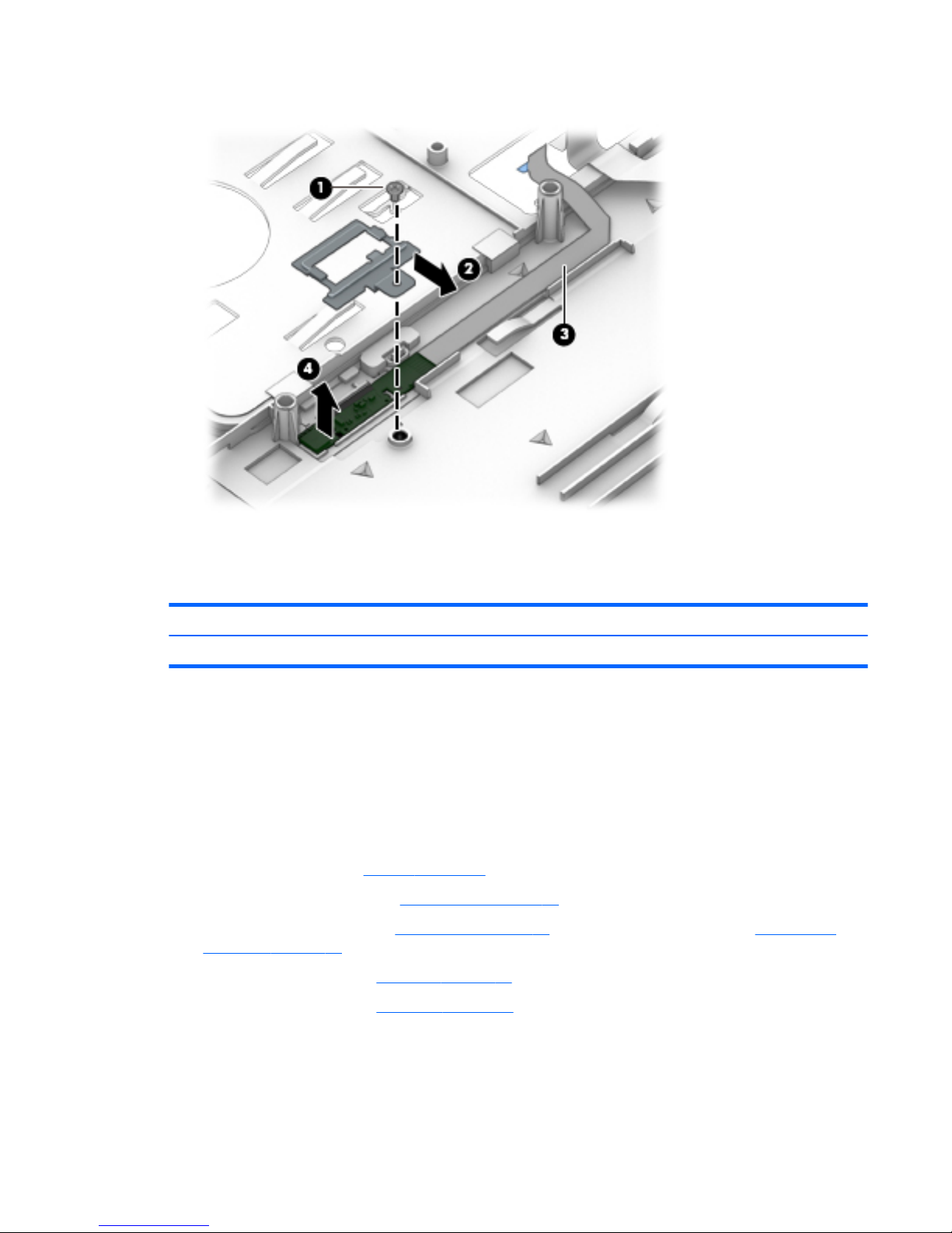
5. Remove the fingerprint reader (4).
Reverse this procedure to install the fingerprint reader.
Power button board
Description Spare part number
Power button board (includes cable) 733636-001
Before removing the power button board, follow these steps:
1. Shut down the computer. If you are unsure whether the computer is off or in Hibernation, turn the
computer on, and then shut it down through the operating system.
2. Disconnect all external devices connected to the computer.
3. Disconnect the power from the computer by first unplugging the power cord from the AC outlet and
then unplugging the AC adapter from the computer.
4. Remove the battery (see Battery on page 45)
5. Remove the service cover (see Service cover on page 47).
6. Remove the optical drive (see Optical drive on page 56) or upgrade bay hard drive (see Upgrade Bay
hard drive on page 58).
7. Remove the keyboard (see Keyboard on page 61).
8. Remove the top cover (see Top cover on page 71).
Remove the power button board:
1. Turn the top cover upside down with the front toward you.
2. Release the power button board cable through the opening in top cover (1).
Component replacement procedures 79
Page 92
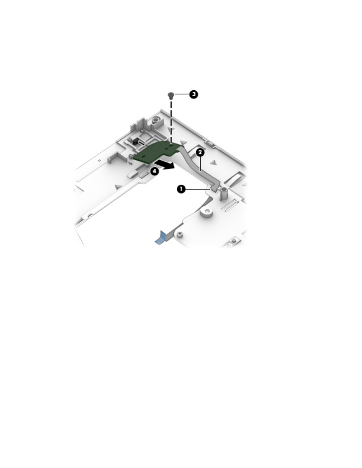
3. Detach the power button board cable (2) from the top cover. (The power button board cable is attached
to the top cover with double-sided tape.)
4. Remove the Phillips PM2.0×3.0 screw (3) that secures the power button board to the top cover.
5. Lift the bottom edge of the power button board, and then remove the power button board by sliding it
up and away at an angle from the tab that secures it in place (4).
Reverse this procedure to install the power button board.
80 Chapter 6 Removal and replacement procedures for Authorized Service Provider parts
Page 93

Display assembly
The display bezel, webcam/microphone module, microphone module, and display panel can be removed
without removing the entire display assembly. See Display bezel on page 66, Webcam/microphone module
on page 70, and Display panel on page 68 for more information.
Description Spare part number
17.3-in, AG, FHD, LED, UWVA display assembly for use on computer models equipped with a webcam 784207-001
17.3-in, AG, FHD, LED, UWVA display assembly for use on computer models not equipped with a webcam 784206-001
Before removing the display assembly, follow these steps:
1. Shut down the computer. If you are unsure whether the computer is off or in Hibernation, turn the
computer on, and then shut it down through the operating system.
2. Disconnect all external devices connected to the computer.
3. Disconnect the power from the computer by first unplugging the power cord from the AC outlet and
then unplugging the AC adapter from the computer.
4. Remove the battery (see Battery on page 45).
5. Remove the service cover (see Service cover on page 47).
6. Remove the optical drive (see Optical drive on page 56) or upgrade bay hard drive (see Upgrade Bay
hard drive on page 58).
7. Remove the keyboard (see Keyboard on page 61).
8. Remove the top cover (see Top cover on page 71).
Remove the display assembly:
1. Turn the computer upside down with the front toward you.
Component replacement procedures 81
Page 94
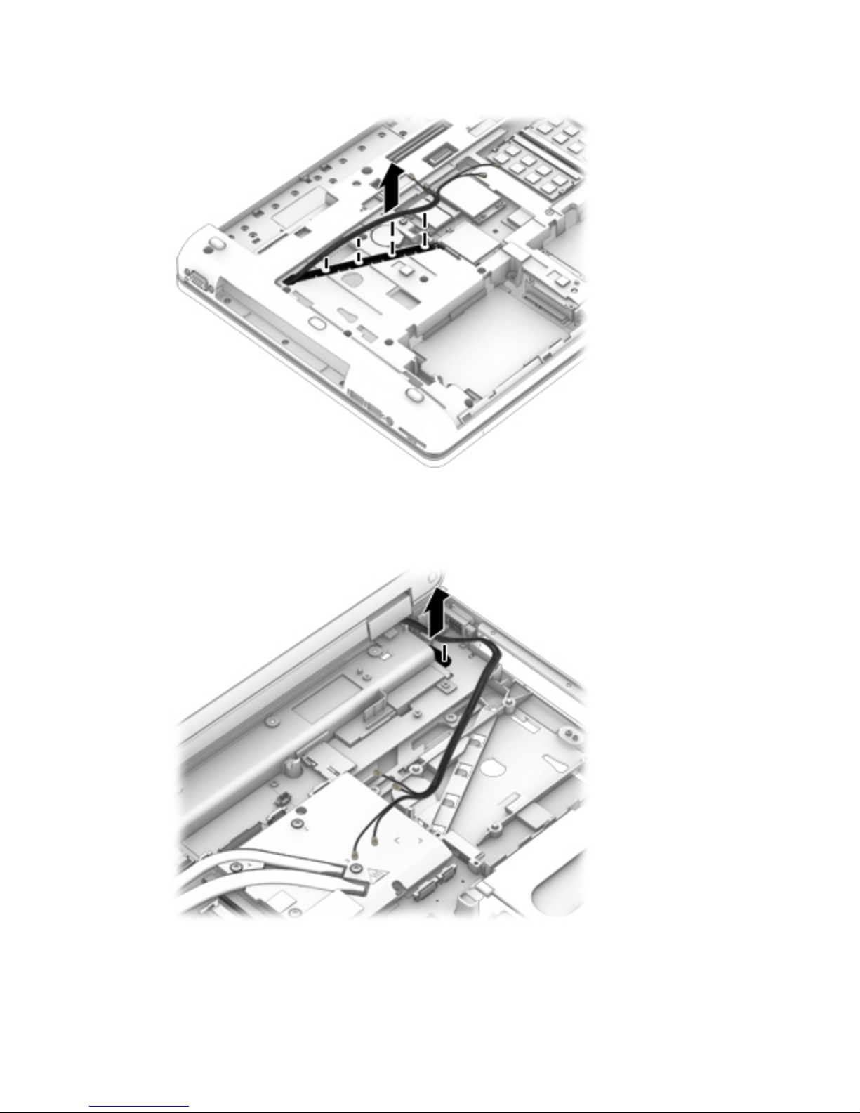
2. Release the WLAN and WWAN antenna cables from the routing channel built into the base enclosure.
3. Turn the computer right side up with the front toward you.
4. Open the computer as far as it will open.
5. Release the WLAN and WWAN antenna cables through the opening in the base enclosure.
6. Close the computer.
7. Position the computer with the rear toward you.
8. Remove the four Torx T8M2.5×3.0 screws (1) that secure the hinge cover to the computer.
82 Chapter 6 Removal and replacement procedures for Authorized Service Provider parts
Page 95
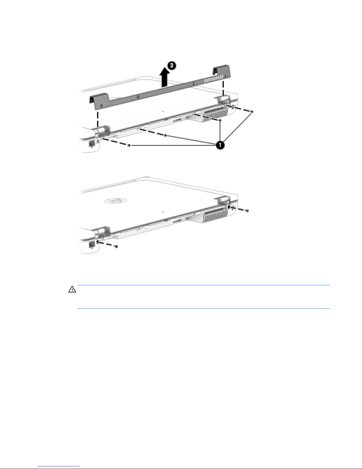
9. Remove the hinge cover (2).
The hinge cover is available using spare part number 733634-001.
10. Remove the two Torx T8M2.5×7.0 screws that secure the display assembly to the computer.
11. Position the computer with the front toward you.
12. Open the computer as far as it will open.
CAUTION: Support the display assembly when removing the display assembly screws in the following
steps. Failure to support the display assembly can result in damage to the display assembly and other
components.
13. Remove the two Torx T8M2.0×5.0 screws (1) that secure the display panel cable to the system board.
14. Remove the display panel cable bracket (2).
15. Detach the display panel cable (3) from the base enclosure. (The display panel cable is attached to the
base enclosure with double-sided tape.)
Component replacement procedures 83
Page 96
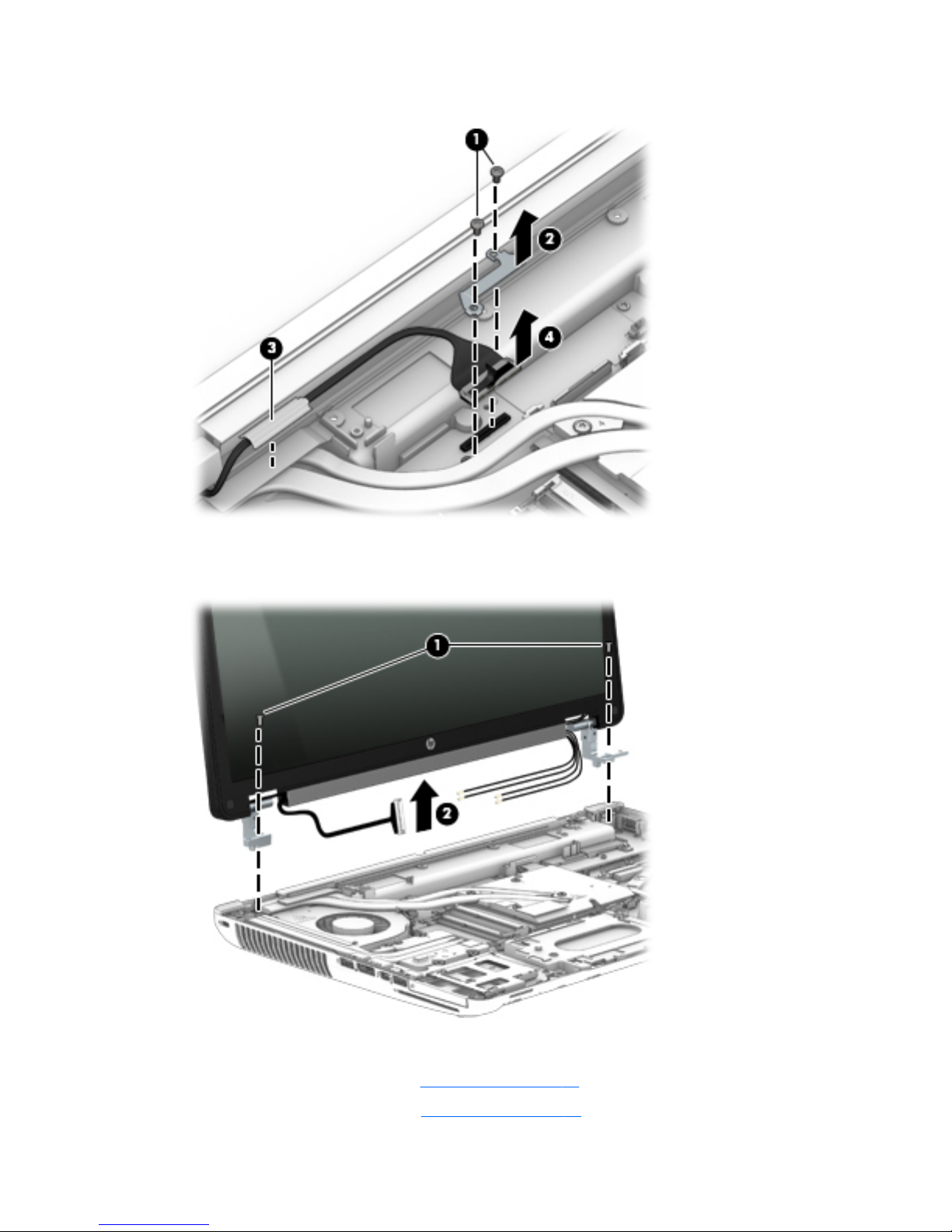
16. Disconnect the display panel cable from the system board (4).
17. Remove the two Torx T8M2.5×7.0 screws (1) that secure the display assembly to the computer.
18. Remove the display assembly (2).
19. If it is necessary to replace the display hinges:
●
Remove the display bezel (see Display bezel on page 66)
●
Remove the display panel (see Display panel on page 68)
84 Chapter 6 Removal and replacement procedures for Authorized Service Provider parts
Page 97
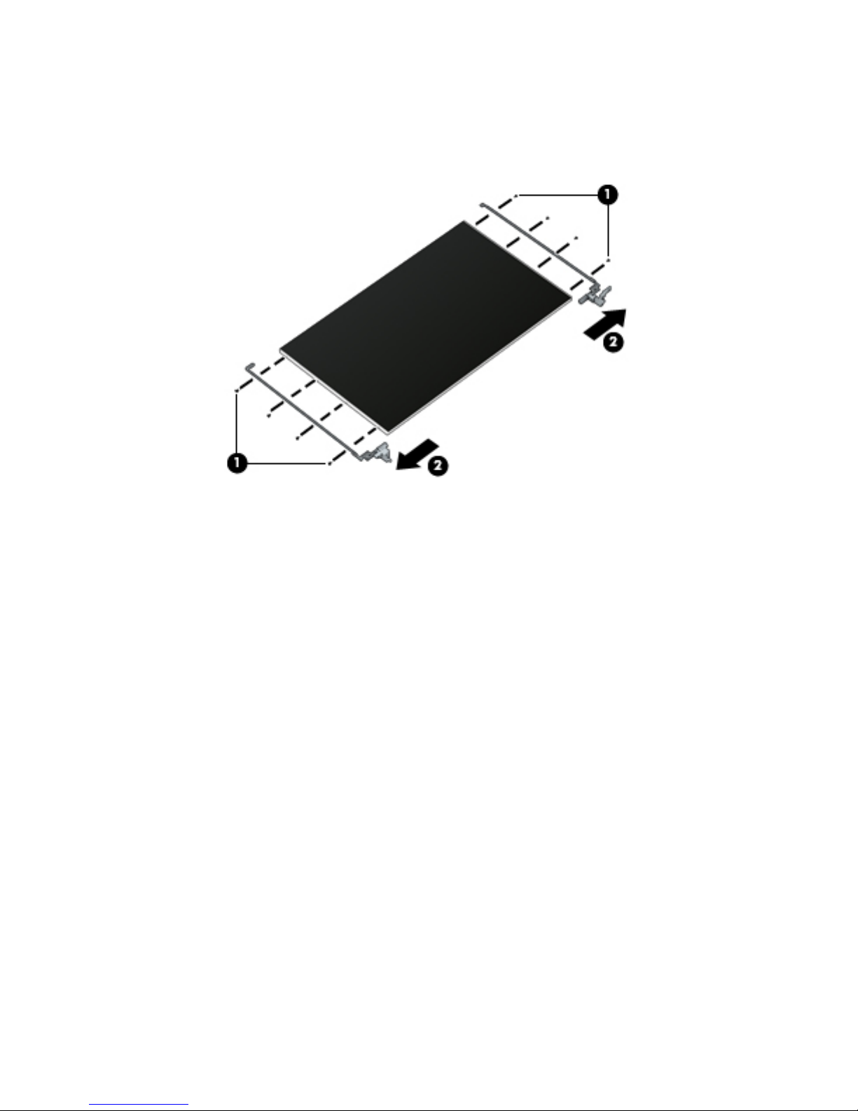
a. Remove the eight Phillips PM2.0×3.0 screws (1) that secure the hinge assemblies to the
display panel.
b. Remove the hinge assemblies (2).
The hinge assemblies are available in the Display Hinge Kit using spare part number 733634-001.
20. If it is necessary to remove the LVDS board:
a. Disconnect the display panel cable (1) from the display panel.
b. Disconnect the LVDS board cable (2) from the display panel.
c. Remove the two Phillips PM1.5×3.0 screws (3) that secure the LVDS board to the display panel.
Component replacement procedures 85
Page 98
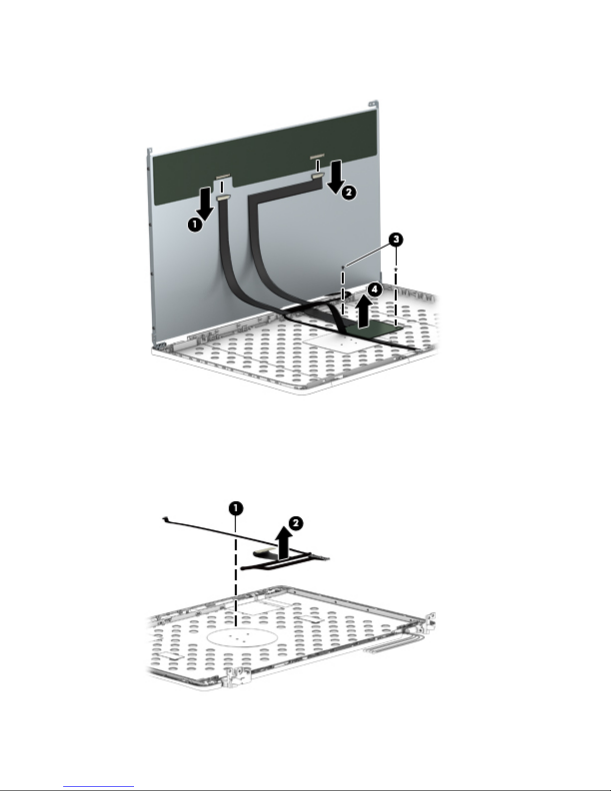
d. Remove the LVDS board (4).
The LVDS board is available using spare part number 741282-001.
21. If it is necessary to replace the display panel cable:
a. Detach the display panel cable (2) from the display enclosure. (The display panel cable is attached
to the display enclosure with double-sided tape.)
b. Remove the display panel cable (2).
The display panel cable is available in the Cable Kit, 785212-001.
Reverse this procedure to install the display assembly.
86 Chapter 6 Removal and replacement procedures for Authorized Service Provider parts
Page 99

ExpressCard assembly
Description Spare part number
ExpressCard assembly 794578-001
Before removing the ExpressCard assembly, follow these steps:
1. Shut down the computer. If you are unsure whether the computer is off or in Hibernation, turn the
computer on, and then shut it down through the operating system.
2. Disconnect all external devices connected to the computer.
3. Disconnect the power from the computer by first unplugging the power cord from the AC outlet and
then unplugging the AC adapter from the computer.
4. Remove the battery (see Battery on page 45).
5. Remove the service cover (see Service cover on page 47).
6. Remove the optical drive (see Optical drive on page 56) or upgrade bay hard drive (see Upgrade Bay
hard drive on page 58).
7. Remove the keyboard (see Keyboard on page 61).
8. Remove the top cover (see Top cover on page 71).
Remove the ExpressCard assembly:
1. Remove the Torx T8M2.5×4.0 screw (1) that secures the light pipe to the computer.
2. Remove the light pipe (2).
3. Remove the four Torx T8M2.5×4.0 screws (3) that secure the ExpressCard assembly to the system
board.
4. Lift up on the right side (4) of the ExpressCard assembly to disconnect it from the
system board connector.
Component replacement procedures 87
Page 100
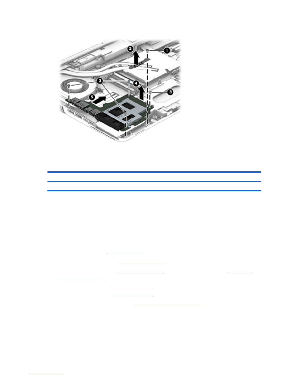
5. Remove the ExpressCard assembly (5) by sliding it up and to the right at an angle.
Reverse this procedure to install the ExpressCard assembly.
Smart Card reader
Description Spare part number
Smart Card reader (includes cable) 742159-001
Before removing the Smart Card reader, follow these steps:
1. Shut down the computer. If you are unsure whether the computer is off or in Hibernation, turn the
computer on, and then shut it down through the operating system.
2. Disconnect all external devices connected to the computer.
3. Disconnect the power from the computer by first unplugging the power cord from the AC outlet and
then unplugging the AC adapter from the computer.
4. Remove the battery (see Battery on page 45).
5. Remove the service cover (see Service cover on page 47).
6. Remove the optical drive (see Optical drive on page 56) or upgrade bay hard drive (see Upgrade Bay
hard drive on page 58).
7. Remove the keyboard (see Keyboard on page 61).
8. Remove the top cover (see Top cover on page 71).
9. Remove the ExpressCard assembly (see ExpressCard assembly on page 87).
Remove the Smart Card:
1. Remove the three Phillips PM2.5×4.0 screws (1) that secure the Smart Card reader to the system board.
2. Lift the Smart Card reader slightly upward and toward the left (2).
88 Chapter 6 Removal and replacement procedures for Authorized Service Provider parts
 Loading...