

Page 1

Edit the Document Title Variable
AUTODESK®
LUSTRE
®
2007
A Discreet® Systems product
HP xw8400 WORKSTATION
Hardware Setup Guide
Page 2

Autodesk® Lustre® 2007
© 2000-2006 Autodesk Canada Co./Autodesk, Inc. and/or its licensors. All rights reserved.
All user documentation ("User Documentation") contains proprietary and confidential information of Autodesk Canada Co./Autodesk, Inc. and/or its licensors. The User
Documentation is protected by national and international intellectual property laws and treaties. All rights reserved. Use of the Documentation is subject to the terms of the
software license agreement that governs the use of the software product to which the User Documentation pertains ("Software").
This publication, or parts thereof, may not be reproduced in any form, by any method, for any purpose.
Autodesk Canada Co./Autodesk, Inc., reserves the right to revise and improve its products as it sees fit. This publication describes the state of this product at the time of its
publication, and may not reflect the product at all times in the future.
AUTODESK CANADA CO./AUTODESK, INC., MAKES NO WARRANTY, EITHER EXPRESS OR IMPLIED, INCLUDING BUT NOT LIMITED TO ANY IMPLIED
WARRANTIES OF MERCHANTABILITY OR FITNESS FOR A PARTICULAR PURPOSE REGARDING THESE MATERIALS, AND MAKES SUCH MATERIALS
AVAILABLE SOLELY ON AN "AS-IS" BASIS.
IN NO EVENT SHALL AUTODESK CANADA CO./AUTODESK, INC., BE LIABLE TO ANYONE FOR SPECIAL, COLLATERAL, INCIDENTAL, OR CONSEQUENTIAL
DAMAGES IN CONNECTION WITH OR ARISING OUT OF PURCHASE OR USE OF THESE MATERIALS. THE SOLE AND EXCLUSIVE LIABILITY TO AUTODESK
CANADA CO./AUTODESK, INC., REGARDLESS OF THE FORM OF ACTION, SHALL NOT EXCEED THE PURCHASE PRICE OF THE MATERIALS DESCRIBED
HEREIN.
Autodesk Trademarks
The following are registered trademarks or trademarks of Autodesk, Inc., in the USA and other countries: 3DEC (design/logo), 3December, 3December.com, 3ds Max, ActiveS hapes, Actrix,
ADI, Alias, Alias (swirl design/logo), AliasStudio Alias|Wavefront (design/logo), ATC, AUGI, AutoCAD, AutoCAD Learning Assistance, AutoCAD LT, AutoCAD Simulator, AutoCAD SQL
Extension, AutoCAD SQL Interface, Autodesk, Autodesk Envision, Autodesk Insight, Autodesk Intent, Autodesk Inventor, Autodesk Map, Autodesk MapGuide, Autodesk Streamline,
AutoLISP, AutoSnap, AutoSketch, AutoTrack, Backdraft, Built with ObjectARX (logo), Burn, Buzzsaw, CAiCE, Can You Imagine, Character Studio, Cinestream, Civil 3D, Cleaner, Cleaner
Central, ClearScale, Colour Warper, Combustion, Communication Specification, Constructware, Content Explorer, Create>what’s>Next (design/logo), Dancing Baby (image), DesignCenter,
Design Doctor, Designer's Toolkit, DesignKids, DesignProf, DesignServer, DesignStudio, Desi gn|Studio (design/logo), Design Your World, Design Your World (design/logo), DWF, DWG,
DWG Linking, DWG (logo), DWG Tru eConvert, DWG TrueView, DXF, EditDV, Education by Design, Extending the Design Team, FBX, Filmbox, GDX Driver, Gmax, Heads-up Design,
Heidi, HOOPS, HumanIK, i-drop, iMOUT, Incinerator, IntroDV, Kaydara, Kaydara (design/logo), LocationLogic, Lustre, Maya, Mechanical Desktop, MotionBuilder, ObjectARX,
ObjectDBX, Open Reality, PolarSnap, PortfolioWall, Powered with Autodesk Technology, Productstream, ProjectPoint, Re actor, RealDWG, Real-time Roto, Render Queue, Revit, ShowCase,
SketchBook, StudioTools, Topobase, Toxik, Visual, Visual Bridge, Visual Constr uction, Visual Drainage, Visual Hydro, Visual Landscape, Visual Roads, Visual Survey, Visual Syllabus, Visual
Toolbox, Visual Tugboat, Visual LISP, Voice Reality, Volo, and Wiretap.
Autodesk Canada Co. Trademarks
The following are registered trademarks of Autodesk Canada Co. in the US A and/or Canada and other countries: Discreet, Fire, Flame, Flint, Frost, Inferno, River, Smoke, Sparks, Stone, Wire.
The following are trademarks of Autodesk Canada Co., in the USA, Canada, and/or other countries: Backburner, Multi-Master Editing.
Third-Party Trademarks
All other brand names, product names, or trademarks belong to their respective holders.
GOVERNMENT USE
Use, duplication, or disclosure by the U.S. Government is subject to restrictions as set forth in FAR 12.212 (Commercial Computer Software-Restricted Rights) and DFAR
227.7202 (Rights in Technical Data and Computer Software), as applicable. Manufacturer is Autodesk Canada Co./Autodesk, Inc., 10 Duke Street, Montreal, Quebec, Canada,
H3C 2 L7.
.
Third-Party Copyright Notices
Portions relating to Copyright © 2003 NetGroup, Poliecnico di Torino. All rights reserved.
Title: Hardware Setup Guide for HP xw8400 Workstations
Document Version: 2
Date: February 9, 2007
Page 3

contents
Contents
1 Introduction 1
Summary . . . . . . . . . . . . . . . . . . . . . . . . . . . . . . . . . . . . . . . . . . . . . . . . . . . . . . . . . . . . . . . 1
About This Guide . . . . . . . . . . . . . . . . . . . . . . . . . . . . . . . . . . . . . . . . . . . . . . . . . . . . . . . . 1
Revision History . . . . . . . . . . . . . . . . . . . . . . . . . . . . . . . . . . . . . . . . . . . . . . . . . . . . . . . . . 2
The Lustre Workgroup . . . . . . . . . . . . . . . . . . . . . . . . . . . . . . . . . . . . . . . . . . . . . . . . . . . 2
Optional Lustre Components . . . . . . . . . . . . . . . . . . . . . . . . . . . . . . . . . . . . . . . . . . . . . . 3
Typical Configuration Overview . . . . . . . . . . . . . . . . . . . . . . . . . . . . . . . . . . . . . . . . . . . 4
Workflow for Hardware Setup and Application Installation . . . . . . . . . . . . . . . . . . . 5
Related Documentation. . . . . . . . . . . . . . . . . . . . . . . . . . . . . . . . . . . . . . . . . . . . . . . . . . . 6
Hardware Configuration Guidelines . . . . . . . . . . . . . . . . . . . . . . . . . . . . . . . . . . . . . . . . 7
Notation Conventions . . . . . . . . . . . . . . . . . . . . . . . . . . . . . . . . . . . . . . . . . . . . . . . . . . . . 12
Contacting Customer Support . . . . . . . . . . . . . . . . . . . . . . . . . . . . . . . . . . . . . . . . . . . . . 13
2Connecting Peripherals 15
Summary . . . . . . . . . . . . . . . . . . . . . . . . . . . . . . . . . . . . . . . . . . . . . . . . . . . . . . . . . . . . . . . 15
Workflow for Connecting Peripherals . . . . . . . . . . . . . . . . . . . . . . . . . . . . . . . . . . . . . . 15
Connection Diagram for the HP xw8400 . . . . . . . . . . . . . . . . . . . . . . . . . . . . . . . . . . . . 16
Connecting the Monitor . . . . . . . . . . . . . . . . . . . . . . . . . . . . . . . . . . . . . . . . . . . . . . . . . . 17
Connecting the Keyboard, Mouse, and Monitor Calibration Device . . . . . . . . . . . . 18
Connecting Storage . . . . . . . . . . . . . . . . . . . . . . . . . . . . . . . . . . . . . . . . . . . . . . . . . . . . . . 18
Network Connections . . . . . . . . . . . . . . . . . . . . . . . . . . . . . . . . . . . . . . . . . . . . . . . . . . . . 19
3 Connecting System Components 21
Summary . . . . . . . . . . . . . . . . . . . . . . . . . . . . . . . . . . . . . . . . . . . . . . . . . . . . . . . . . . . . . . . 21
iii
Page 4

Con
tents
Workflow for Connecting System Components in the Lustre Workgroup . . . . . . . 21
Connecting the Autodesk Control Surface. . . . . . . . . . . . . . . . . . . . . . . . . . . . . . . . . . . 22
Assigning an IP Address to the Autodesk Control Surface . . . . . . . . . . . . . . . . . . . . . 25
Configuring Lustre to Connect to the Autodesk Control Surface . . . . . . . . . . . . . . . 27
Connecting a Stand-Alone Tablet . . . . . . . . . . . . . . . . . . . . . . . . . . . . . . . . . . . . . . . . . . 27
Connecting the Slave Renderer to a Lustre Workstation. . . . . . . . . . . . . . . . . . . . . . . 28
Connecting Video I/O to a Master or HD Station. . . . . . . . . . . . . . . . . . . . . . . . . . . . . 30
Connecting to a High-Speed Data Link Device (HSDL) . . . . . . . . . . . . . . . . . . . . . . . 32
Index 35
iv
Page 5

Summary
About This Guide . . . . . . . . . . . . . . . . . . . . . . . . . . . . . . . . . . . . . . . . . . . . . . . . . . . . . . . . . 1
Revision History . . . . . . . . . . . . . . . . . . . . . . . . . . . . . . . . . . . . . . . . . . . . . . . . . . . . . . . . . . 2
The Lustre Workgroup . . . . . . . . . . . . . . . . . . . . . . . . . . . . . . . . . . . . . . . . . . . . . . . . . . . . 2
Optional Lustre Components . . . . . . . . . . . . . . . . . . . . . . . . . . . . . . . . . . . . . . . . . . . . . 3
Typical Configuration Overview . . . . . . . . . . . . . . . . . . . . . . . . . . . . . . . . . . . . . . . . . . 4
Workflow for Hardware Setup and Application Installation . . . . . . . . . . . . . . . . 5
Related Documentation . . . . . . . . . . . . . . . . . . . . . . . . . . . . . . . . . . . . . . . . . . . . . . . . . . 6
Hardware Configuration Guidelines . . . . . . . . . . . . . . . . . . . . . . . . . . . . . . . . . . . . . . 7
Notation Conventions . . . . . . . . . . . . . . . . . . . . . . . . . . . . . . . . . . . . . . . . . . . . . . . . . . . 12
Contacting Customer Support . . . . . . . . . . . . . . . . . . . . . . . . . . . . . . . . . . . . . . . . . . . 13
About This Guide
This guide describes how to set up the HP xw8400 workstation and the other hardware
components of your Autodesk® Lustre® 2007 workgroup. The HP xw8400 workstation is
available for Lustre systems on Windows®, as well as for Autodesk Incinerator™ Lustre systems
on Linux®. To install and configure hardware and software components, use this guide in
conjunction with the following documents: the Autodesk Lustre Software Installation Guide for
Windows Workstations, the Autodesk Incinerator 2007 Installation and User’s Guide for Lustre
with Incinerator, and the Stone Direct Configuration Guide for this release.
Introduction
N
OTE
:
In most cases, both hardware setup and application installation are done on delivery by an
authorized technician, so you may not need to perform some of the procedures in these guides.
The latest versions of a ll guides are available in PDF format from t he Web at www.autodesk.com/
discreet-documentation. For best results viewing and printing these PDF files, use Adobe®
Acrobat® Reader™ 6 or later, or Xpdf viewer.
1
Page 6
1
Introduction
N
OTE
:
If you do not have Acrobat Reader, you can download a free copy from the Adobe Web site
(
www.adobe.com
Web site (
www.foolabs.com/xpdf/
Revision History
This document is updated as necessary throughout the life cycle of the release. This section
describes all additions and modifications made to this document since its initial publication.
N
OTE
:
Minor changes that do not have an impact on the technical content of this guide, such as
typographical errors or changes to section names, are not included in the revision history.
Modification Item Page Released At
Added
Updated
Updated
Updated
Updated
Updated
Updated
Updated
Updated
). If you do not have Xpdf viewer, you can download a free copy from the Xpdf
).
Revision History
Contacting Customer Support; Japan
Linux-Based Connection Diagram for the HP xw8400
Connecting the Monitor (EIZO 24-inch LCD)
Monitor Calibration Device on Linux Workstations
Connecting the Autodesk Control Surface
Configuring the Autodesk Control Surface on Linux
Connecting the Slave Renderer
Connecting Video I/O to a Master or HD Station
22007
13 2007
16 2007
17 2007
18 2007
22 2007
25 2007
28 2007
30 2007
The Lustre Workgroup
Lustre is a modular system that you can configure and expand to suit your needs. The features
you purchase determine the hardware included with your system.
Central to any system is the Master Station or HD Station. The Master Station is a high-end
Windows- or Linux-based PC designed to accommodate real-time interactivity in a clientattended or supervised session. You can add a Lustre Station to improve the efficiency of your
pipeline.
Master Station —
where the colorist works together with the cinematographer. Contains an extensive creative
toolset for more elaborate visual design and grading using up to 4K resolution and 16-bit files
and for completing tasks like dust busting, conforming, rotoscoping and capture/playout.
HD Station —
mastering short-form and long-form HDTV projects, as well as HD film projects. Input up to
10-bit 2K and output HD and SD.
2
Includes the full Lustre toolset and is designed for GPU-accelerated sessions
Cost-effective GPU workstation for conforming, preparing, grading and
Page 7

Optional Lustre Components
Lustre Station —
Tasks that do not require the direct intervention or supervision of the
colorist can be efficiently handled by a Lustre Station. Multiple Lustre Stations can work in
parallel to increase throughput and can be used for tasks such as dust-busting, preparatory
work, fine-tuning creative sessions, conforming data from EDLs, updating editorial changes
using change lists, and mastering to different formats using the real-time deliverables function.
Lustre Workstation Features
The following table describes the features available to each Lustre workstation.
N
OTE
:
The features of Lustre 2007 may vary based on your hardware platform. Consult the
Notes
for your release for specific system information.
Station Configuration
Master Station
Lustre HD Station
Lustre Station
Default —
HSDL video formats and the DI Pack, which consists of infrared channel
dust removal and support for all standard input and output resolutions
and bit-depths. Certain features require add-on licensing.
Add-Ons —
configuration: the Slave Renderer and up to three panels for the Autodesk
control surface. The Slave Renderer requires a separate license.
Default —
Station description). File input is limited to 2K resolution. File output is
limited to HD resolution, 10-bit. Certain features require add-on licensing.
Add-Ons —
configuration: SD and HD I/O, dual link and HSDL video formats, the Slave
Renderer, and up to three panels for the Autodesk control surface. The
Slave Renderer requires a separate license.
Default —
colour grading. The DI Pack (see the Master Station description) is also
included, along with full dust removal functionality, and the ability to
create geometries and masks.
With Primary Colour Correction —
option as well as primary colour grading.
Add-Ons —
configuration or the With Primary Colour Correction configuration, and
require an additional license: SD and HD I/O, dual link and HSDL video
formats, and up to three panels for the Autodesk control surface.
The Slave Renderer requires a separate license.
All features are available including SD and HD I/O, dual link and
The following features can be added to the Default
Includes all features except for the DI Pack (see the Master
The following features can be added to the Default
All features are available except for primary and secondary
Includes all features of the default
The following features are available for either the Default
Release
Optional Lustre Components
You can expand the features of your Lustre system and improve the efficiency of your workflow
by adding any of the following components.
3
Page 8

1
Introduction
Control Surface —
The Autodesk control surface provides improved interactiv ity when colour
grading film and video footage. You can perform many of the same tasks you do in the Lustre
user interface using the control surface.
Video I/O —
Video I/O is provided by the DVS Centaurus® board, which consists of an HD/
SD board and a breakout box. This configuration provides real-time SDI input and output of
uncompressed 8- or 10-bit HD or SD video in both YUV (4:2:2) and RGB formats (4:4:4 or
4:2:2).
For a list of supported video formats, see the Autodesk Lustre 2007 User’s Guide.
Slave Renderer —
The Slave Renderer is a rack-mounted server that is connected directly to
the Lustre workstation. It frees system resources by off-loading render tasks on an ‘as-needed’
basis, thus ensuring real-time interaction on the Lustre system.
Background Renderer —
Background rendering frees up Lustre workstations for colour
grading. You can use up to eight background rendering machines to process your final frames.
N
OTE
:
For a list of Incinerator system components, refer to the
Installation and User’s Guide
Typical Configuration Overview
The following illustration shows a typical configuration, including the Master Station, Lustre
Station, and other optional components.
Autodesk Incinerator 2007
4
Page 9
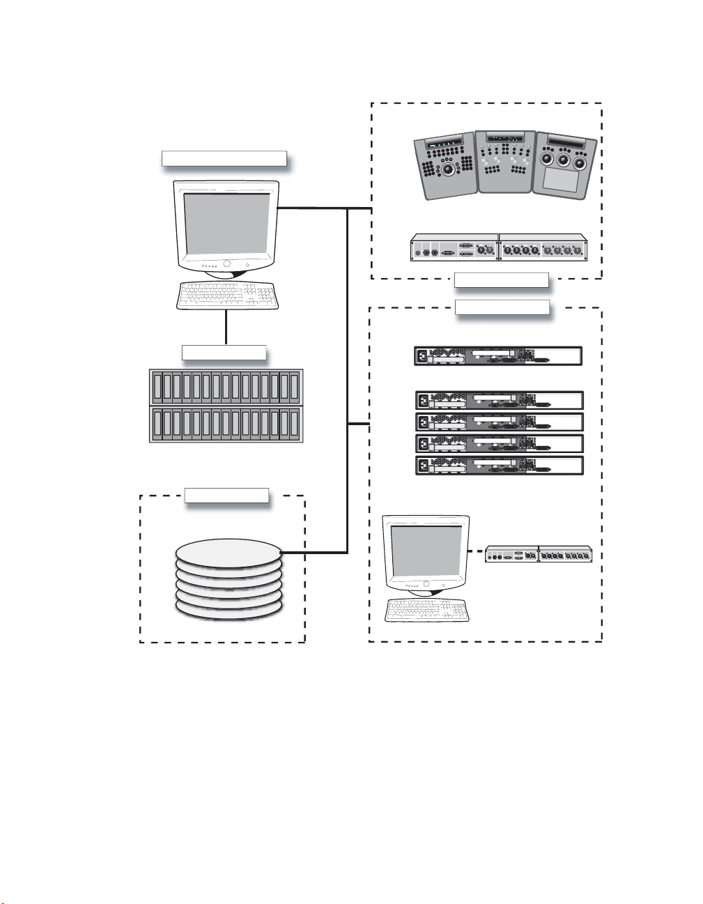
Lustre Master Workstation
Workflow for Hardware Setup and Application Installation
Control Surface
Sh Mid
High
R G B
BrightBright
Hue Brightness Saturation
+
G+ B+R+
G - B -R -
Proxy
Sp
li
t
e
p
Wi
Multi
ll
ti
S
O/P
Matte
Out
In
LTC
-
A
T
L
1/2
3/4 5/6 7/8 1/2 3/4 5/6 7/8
In
Shadow Contrast Brightnes
F
2
F
1
F
3
s
F
5
F
4
F
6
F
8
F
7
F
9
Out
9
1
0
0
0
.0
1
0
0
0
#
c
is
M
S
&
e
P
id
s
t
u
m
O
o
e
e
G
sid
y
In
e
K
e
urv
C
e
d
a
r
r
G
tP
u
O
r
P
In
E
R
O
CM
S
I
M
S
&
P
M
O
E
G
Y
E
K
S
E
V
R
EO
U
R
C
O
M
E
D
A
R
G
T
U
IN
9
8
7
6
5
4
O
D
DO
E
R
O
D
N
U
T
R
E
V
E
R
OR
RS
U
C
OFFSET
L
L
CA
E
R
A
P
I
CL
3
2
1
P
M
O
C
.
0
+/-
GRADE
R
E
T
N
E
CUE
/B
T
L
A
Video I/O (DVS Centaurus + Break out box)
OutOut
RS422A
RS422BGPICVBSWclkAudio
Peripheral Options
Lustre Storage
SAN access
Lustre Station
Storage Volume
N
OTE
:
For an Incinerator system configuration overview, refer to the
Installation and User’s Guide
Network Options
Slave Renderer
Background Rendering (burn)
In Out
OutOut
RS422A
RS422BGPICVBSWclkAudio
LTC
Video I/O
Autodesk Incinerator 2007
1/2
3/4 5/6 7/8 1/2 3/4 5/6 7/8
In
Out
Workflow for Hardware Setup and Application Installation
The following procedure provides the general workflow for installing Lustre on an HP xw8400
workstation running Windows.
5
Page 10

1
Introduction
For workflow information related to the HP xw8400 running on Linux for Incinerator, refer to
the Autodesk Incinerator Installation and User’s Guide.
To install Lustre on an HP xw8400 workstation:
1. Review the guidelines for working with hardware components. See “Hardware
Configuration Guidelines” on page 7.
2. Connect all peripherals (mouse, keyboard, graphics monitor, storage, etc.) to each
workstation in your workgroup, and connect each workstation to the network. See Chapter
2, “Connecting Peripherals,” on page 15.
3. Connect your workstation to Autodesk Stone® Direct storage. See the Stone Direct
Configuration Guide.
4. Connect your Master or HD Station to a Slave Renderer, a control surface, tablet, and video
I/O components. See Chapter 3, “Connecting System Components,”
N
OTE
:
The Slave Renderer is not used in Incinerator configurations.
5. Perform the procedures in the Autodesk Lustre 2007 Software Installation Guide or the
on page 21.
Autodesk Incinerator 2007 Installation and User’s Guide to install and license Lustre and
Incinerator.
Related Documentation
The following table describes the documentation associated with your application. For a
detailed list of the latest documentation, see your release notes.
User Guides Provides
Autodesk Lustre 2007 User’s Guide
Autodesk Control Surface User’s Guide
Autodesk Lustre 2007 What’s New
Autodesk Lustre 2007 Hot Keys Card
Autodesk Lustre (and Incinerator) Release
Notes
(for this release)
Autodesk Lustre (and Incinerator) Fixed
and Known Bug List
(for this release)
6
Detailed instructions on using the software.
Detailed instructions on using the Autodesk
control surface and the Tangent CP100.
A list of the new features for this release.
A list of the most frequently used hot keys.
A complete list of documentation and information
on late-breaking features.
A complete list of fixed and known bugs for this
release.
Page 11

Hardware Configuration Guidelines
Installation and Configuration Guides Provides
Hardware Setup Guide
(for your workstation)
Stone Direct Configuration Guide
(for this release)
Autodesk Lustre 2007 Software Installation
Guide
(for your operating system)
Stone and Wire Filesystem and Networking
Guide
(for this release)
Other Guides Provides
Autodesk Lustre Sparks API Reference
Guide
Autodesk Backburner 2007 Installation and
User’s Guide
Information on how to set up your workstation
and video I/O peripherals.
Provides detailed connectivity diagrams and
configuration procedures for your Stone storage
arrays.
Information about installing and licensing your
Autodesk Lustre software.
Note: For Lustre and Incinerator, see the Autodesk
Incinerator Installation and User’s Guide.
Procedures for configuring your Wiretap™
services.
Instructions for developing Sparks® plugins for
Lustre.
Information on how to install, set up, and use
Backburner™.
Consult the Autodesk Web site at www.autodesk.com/discreet-documentation for the latest
version of guides, release notes, and fixed and known bugs documents.
Hardware Configuration Guidelines
In most cases, hardware integration and application installation is done on delivery by an
authori zed technician, and some of the pro cedures in this guide may not be necessary. Still, it is
a good idea to read through all chapters to familiarize yourself with the configuration
procedures for the following reasons:
• Many suspected problems with your Lustre system may be due to loosened connections or
improperly configured devices. This guide helps you troubleshoot problems by providing
information about properly configured systems.
• If you need to call Customer Support, familiarity with this guide puts you in a better position
to provide diagnostic information.
• If you want to move your Lustre system at any time , or upgr ade ce rtain hardware components ,
information in this guide is crucial.
Although this guide, in conjunction with the Autodesk Stone Direct Configuration Guide,
provides complete inform ation regardi ng hardware comp onent configu ration, it s hould only b e
undertaken by an experienced hardware integrator. This individual should be familiar with the
7
Page 12

1
Introduction
Windows or Linux operating systems, HP xw8400 workstations, and peripherals associated
with professional high-performance video and post production of film.
Your Lustre system consists of high-performance hardware that must be configured in an
environment suited to its operational needs. Other considerations include minimizing the risk
of damage due to static discharge and ensuring all components are properly grounded.
Verifying and Updating The System BIOS Version
System configuration is performed by an authorized te chnici an p rior to delivery. As such, some
of the procedures here may not be necessary. Workstation BIOS settings are provided for
informational purposes.
The system BIOS on your workstation must correspond to the certified version required by
your software version. If the BIOS version on your system does not correspond to the table
below, you must update to the certified version.
Product Version Certified BIOS Version
2007 1.15
The BIOS version installed on your system appears onscreen while booting the workstation.
The following procedures describe how to update the BIOS on your workstation.
W
ARNING
:
You should only update the BIOS if you find that it is not at the version listed in this
guide, or if your are advised to do so by Customer Support. Do not update the BIOS with a more
recent version published by the hardware vendor, if it has not been certified by Autodesk
Customer Support.
To update the BIOS on a Windows workstation:
1. Get the BIOS upgrade utility and burn it to a CD.
2. Insert the CD into the CD-ROM drive
3. Reboot the workstation and press F10 to enter BIOS.
4. Select a language.
5. From the File menu, select Flash System ROM.
The Select a Drive menu appears.
6. Click Optical Drive.
The Select a Drive confirmation menu appears.
7. Press F10 to confirm.
8. Select the 7D5_0115.bin file.
8
Page 13

Hardware Configuration Guidelines
The Flash System ROM confirmation menu appears.
9. Press F10 to confirm.
10. Press any key.
System ROM Flash was successful appears.
11. Verify system BIOS settings. See “Verifying BIOS Settings” on page 10.
12. From the File menu, select Save Changes and Exit.
To update the BIOS on a Linux workstation:
1. Load the DKU CD in the DVD-ROM drive on the workstation.
2. Open a terminal.
3. Ty p e :
cd /mnt/cdrom/Utils/BIOS/
Each supported platform has its own directory that contains an .iso file.
N
OTE
:
For more information about updating the BIOS on your workstation, refer to the
README file located in your platform’s directory.
4. Ty p e :
cd ./<platform>
5. Burn the .iso file for your platform onto a CD-ROM and place it in the DVD-ROM drive on
the workstation.
6. Reboot the workstation and press F10 to enter BIOS.
7. Select a language.
8. From the File menu, select Flash System ROM.
The Select a Drive menu appears.
9. Click Optical Drive.
The Select a Drive confirmation menu appears.
10. Press F10 to confirm.
11. Select the 7D5_0115.bin file.
The Flash System ROM confirmation menu appears.
12. Press F10 to confirm.
13. Press any key.
9
Page 14

1
Introduction
System ROM Flash was successful appears.
14. Verify system BIOS settings. See “Verifying BIOS Settings” on page 10.
15. From the File menu, select Save Changes and Exit.
Verifying BIOS Settings
You do not normally need to adjust BIOS settings on your workstation. BIOS settings for the
workstation are provided here for informational purposes only.
To enter the system BIOS, press F10 while booting the workstation.
W
ARNING
:
Before installing Red Hat Linux, it is recommended that you verify the workstation’s
BIOS settings. If the storage SATA emulation option is not set correctly (to Separate IDE Controller),
you must redo Red Hat Linux installation.
The following table lists the proper Autodesk certified BIOS settings. Items not listed are set to
their default factory settings.
BIOS Menu Item Value
Storage, Storage options SATA Emulation Separate IDE
Controller
Storage Boot Order Optical Drive
USB Device
Hard Drive,
Integrated SATA
Hard Drive,
Integrated IDE
Storage, Power, OS Power Management Runtime Power
Management
Storage, Power, OS Power Management Idle Power Savings Normal
Storage, Power, OS Power Management ACPI S3 Support Disabled
Storage, Advanced, Device Options S5 Wake on LAN Disabled
Advanced Slot5 - PCI 133 Slot5 speed
Disabled
100Mhz PCI-x m1
10
Restoring BIOS to Default Factory Settings
The following procedure restores the default factory BIOS settings.
To restore default factory BIOS settings:
1. Press F10 while booting the workstation to enter the system BIOS.
2. From the File menu select Default setup | Restore Factory Settings as
Default.
Page 15

Hardware Configuration Guidelines
3. Press F10 to accept the changes.
4. Select Apply Defaults and Exit.
This restores the original factory system defaults.
Ensuring Proper Environmental Conditions
You should consider the following environmental guidelines for all hardware configuration:
• Make sure the rack in which hardware components are installed is open or ventilated. Follow
the ventilation specifications that apply to your system.
• Place all components in an air-conditioned environment. All hardware components generate
heat and must be kept cool. See “Power and Air Conditioning Requirements”
• Keep all hardware components in a clean, dust-free location.
• Minimize vibration and humidity.
• Do not block the vents on the component housing.
• Do not drape anything, such as a jacket or a blanket, over hardware components.
• Minimize electromagnetic noise by separating digital data and power cables from analog
audio cables and running them in different cable ducts.
on page 11.
Power and Air Conditioning Requirements
The values for power consumption and heat output were recorded on an Autodesk certified
system with all of the required peripheral and certified components.
N
OTE
:
These values can fluctuate if uncertified hardware components or third-party applications
are added to your system. The use of uncertified hardware components or third-party applications
is not supported. Please consult the manufacturer’s documentation for standardized minimum
and maximum values.
The following table summarizes the power consumed by the HP xw8400 system and the heat it
generates under the maximum processing load produced by your Lustre application. For
detailed specifications, including noise output, see the documentation provided by the
manufacturer.
Component Quantity Startup Amps
(120V / 240V)
HP xw8400 1 3.5 / 1.8 2.8 / 1.4 336 1146.4
You must be able to meet the startup power requirement and have a climate control system with
the capacity to maintain the temperature of this component under the maximum processing
11
Max. Amps
(120V / 240V)
Watts Heat
(BTUs)
Page 16

1
Introduction
load. Refer to the following table for standard conversion benchmarks and an example of how
they are used to establish climate control requirements.
Unit Conversion Example
1 Watt = 3.413 BTU 480 Watts = 1638 BTU
12000 BTU = 1 Ton of air conditioning 1638 BTU = 0.137 Ton of air conditioning
Avoiding Damage from Static Electricity
When installing any hardware equipment, take the following precautions to prevent damage to
sensitive components from static discharge:
• Make sure power is turned off on the component you are working on. It is a good idea to
unplug components until all other connections are configured.
• Always wear a grounded static wrist strap. Attach the strap’s alligator clip to any grounded
metal surface on the component’s chassis that you are working on. Place the wristband around
your wrist.
• Do not handle any components unnecessarily, particularly boards and cards that slide in and
out of slots on their parent hardware components.
Grounding Hardware Components
It is important to properly ground any audio components used with Lustre to avoid ground
loops and humming. To ensure audio components are properly grounded, use the XLR-3
cables. Using any other cables may cause humming in the system.
Receiving Your Lustre System
When you receive the shipment containing your Lustre, check all the boxes for dents or other
markings that may indicate damage during transport. If you suspect a component is damaged,
carefully inspect it before setting up the system. If you receive a damaged component, call
Customer Support.
Use the enclosed packing checklist to ensure you received all parts.
Notation Conventions
A number of style conventions are used throughout this guide. These conventions and examples
of their use are shown as follows.
12
Page 17

Convention Example
Text that you enter in a command line or shell appears in
Courier bold. You must press the Enter key after each
command.
Variable names appear in Courier, enclosed in angle brackets.
No spaces are allowed in variable names.
Variables that appear enclosed in square brackets are
optional.
Feedback from the command line or shell appears in Courier.
Directory names, filenames, URLs, and command line utilities
appear in italics.
Contacting Customer Support
You can contact Autodesk Media and Entertainment Customer Support at www.autodesk.com/
support or through one of the following ways:
Location: Contact Information:
Within the Americas: Hotline (North America): 1-800-925-6442
Direct dial: 415-507-5256 (Country code = 1)
8 AM to 8 PM EST Monday to Friday, excluding holidays
me.support@autodesk.com
Contacting Customer Support
rpm -qa
<variable_name>
[<filename>]
limit coredumpsize
/usr/discreet
Within Europe, Middle-East and
Africa:
Within Asia Pacific:
(Excluding India, China, Australia,
New Zealand and Japan)
Within India: Hotline (from Mumbai): +91-22-6695-2244
Within Japan: Hotline (from Tokyo): 0120-107-290
13
Hotline (from London, UK): +44-207-851-8080
9 AM to 5:30 PM (local time)
Monday to Friday, excluding holidays
me.emea.support@autodesk.com
Hotline (from Singapore): +65-6555-0399
9 AM to 6 PM (local time)
Monday to Friday, excluding holidays
me.support.singapore@autodesk.com
9:30 AM to 6:30 PM (local time)
Monday to Friday, excluding holidays
me.support.india@autodesk.com
Direct dial: +81-3-6221-1810
10 AM to 6 PM (local time)
Monday to Friday, excluding holidays
med-sys-support-jp@autodesk.com
Page 18

1
Introduction
Location: Contact Information:
Within China: Direct dial: +86-10-6505-6848
9 AM to 6 PM (local time)
Monday to Friday, excluding holidays
me.support.china@autodesk.com
Within Australia and New Zealand: Hotline (from Melbourne): +1-300-36-8355
Direct dial: +61-3-9876-8355
8 AM to 6 PM AEST
Monday to Friday, excluding holidays
me.support.anz@autodesk.com
Customer support is also available through your Autodesk reseller. To find a reseller near you,
consult the reseller look-up database on the Autodesk web site at www.autodesk.com/resellers.
14
Page 19

Connecting Peripherals
Summary
Workflow for Connecting Peripherals
Connection Diagram for the HP xw8400
Connecting the Monitor
Connecting the Keyboard, Mouse, and Monitor Calibration Device
Connecting Storage
Network Connections
. . . . . . . . . . . . . . . . . . . . . . . . . . . . . . . . . . . . . . . . . . . . . . . . . . 17
. . . . . . . . . . . . . . . . . . . . . . . . . . . . . . . . . . . . . . . . . . . . . . . . . . . . . . 18
. . . . . . . . . . . . . . . . . . . . . . . . . . . . . . . . . . . . . . . . . . . . . . . . . . . . 19
Workflow for Connecting Peripherals
You must connect peripherals (monitor, keyboard, mouse, storage, and network) to each Lustre
workstation before you connect the workstations to video I/O, a control surface, or to other
components in the workgroup.
Connect all hardware peripherals before you boot your workstation.
See the following table for a summary of the steps necessary to connect peripherals to your
Lustre workstation.
. . . . . . . . . . . . . . . . . . . . . . . . . . . . . . . . . . . . . 15
. . . . . . . . . . . . . . . . . . . . . . . . . . . . . . . . . . 16
. . . . . . . . . 18
Step: Refer to:
1. Review the connection diagram for your workstation.
2. Connect a monitor to the workstation.
3. Connect a keyboard, mouse, and calibration device to
your workstation.
4. Connect the workstation to storage.
15
“Connection Diagram for the HP
xw8400”
“Connecting the Monitor”
17.
“Connecting the Keyboard, Mouse,
and Monitor Calibration Device”
page 18.
“Connecting Storage”
on page 16.
on page
on
on page 18.
Page 20

2
T
:4
Connecting Peripherals
Step: Refer to:
5. Connect the workstation to your network.
6. After you connect all the peripherals to your Lustre
workstations, you can connect the workgroup
components together.
Connection Diagram for the HP xw8400
The following diagrams show the connections for the HP xw8400 workstation.
N
OTE
:
These diagrams provide an overview of video I/O connections. For more details, see
“Connecting Video I/O to a Master or HD Station”
HP xw8400 Workstation
(Windows Configuration)
on page 30.
“Network Connections”
on page
19.
Chapter 3, “Connecting System
Components,”
HD-SDI (V2) Out
0:2:2/4:0:0 to 4:4:4
display device or VTR
HD-SDI (V1) Out 4:2:2 to 4:2:2 or 4:4
display device or VTR
on page 21.
Ref In from sync gen
Connect to second
o USB extender for mouse,
keyboar, monitor calibrator
To Slave Renderer
To DVS BOB
To GFX monitor
To storage
1, 4 to SAN; 2, 3 to Stone
Ref In from sync gen
0 to control surface,
1 to LAN, 3 to SAN
16
DVI out on the
main FX5500 card
HD-SDI Out (B) to
4:4:4 VTR
(dual link 0:2:2)
HD-SDI In (B) from
4:4:4 VTR
(dual link 0:2:2)
DVI2 Out to FX5500
SDI daughter card
HD-SDI Out (A) to 4:2:2
VTR (or 4:4:4 dual link)
HD-SDI In (A) from 4:2:2
VTR (or 4:4:4 dual link)
Page 21

T
o USB extender for mouse,
:4
VTR (or 4:4:4 dual link)
keyboar, monitor calibrator
To Incinerator
GigE switch
To DVS BOB
To GFX monitor
To InfiniBand
switch
Ref In from sync gen
0 to control surface,
1 to LAN, 3 to SAN
Connecting the Monitor
HP xw8400 Workstation
(Linux - Incinerator only)
HD-SDI (V2) Out
0:2:2/4:0:0 to 4:4:4
display device or VTR
HD-SDI (V1) Out 4:2:2 to 4:2:2 or 4:4
display device or VTR
Ref In from sync gen
Connect to second
DVI out on the
main FX5500 card
HD-SDI Out (B) to
4:4:4 VTR
(dual link 0:2:2)
HD-SDI In (B) from
4:4:4 VTR
(dual link 0:2:2)
DVI2 Out to FX5500
SDI daughter card
HD-SDI Out (A) to 4:2:2
VTR (or 4:4:4 dual link)
HD-SDI In (A) from 4:2:2
N
OTE
:
The Slave Renderer option is not available for Lustre with Incinerator.
Connecting the Monitor
Connect the monitor to the DVI connection on the Lustre workstation’s graphics card. You can
use the DVI extender cable (DL.CAB-HDTV-FO-82-MM) to extend the cable to a machine
room.
To connect the monitor:
h Use the DVI cable to connect the DVI OUT1 port of the NVIDIA® Quadro® FX5500
graphics card to the DVI-D IN port of the monitor.
N
OTE
:
Although the DVI fiber cable connectors are identical, their functions are different.
Ensure that the connector labeled Send is connected to the Lustre workstation, and that the
17
connector labeled Receive is connected to the monitor.
Page 22

2
Connecting Peripherals
Connecting the Keyboard, Mouse, and Monitor Calibration Device
Connect the mouse, keyboard, and monitor calibration device to the workstation via the 4-port
USB extender (TP.USB-EXT-400).
To connect the keyboard and mouse:
1. Connect the USB keyboard to port 2 on the remote unit of the USB extender.
2. Connect the USB mouse to port 3 on the remote unit of the USB extender.
3. Connect the monitor calibration device (TP.MON-CAL-LCDCRT) to port 4 on the remote
unit of the USB extender.
4. Use an RJ-45 cable to connect the remote unit of the USB extender to the local unit of the
USB extender.
5. Connect the local unit of the USB extender to USB1 port on the workstation.
To enable the Eye-One calibration utility driver:
h Do one of the following:
•
For Windows-based workstations, if the driver is not already installed, you will be prompted
to install the monitor calibration device driver when you restart the workstation. The driver is
available from the
Driver
directory.
• For Linux workstations, once the software installation has been completed, start the
eyeone27 daemon on the workstation. Type: /etc/init.d/eyeone27 start
C:\Program Files\discreet\lustre3.0\Utils\Calibration\Eye-One USB
Connecting Storage
The storage connections for your system depend on whether you are running Lustre on the
Windows or Linux operating system.
Storage for Windows-Based Workstations
Your workstation is configured with a 4-port ATTO Celerity FC-44ES fibre channel adapter.
Consult the “Connection Diagram for the HP xw8400”
channel adapter location and connections.
18
on page 16 as a reference for the fibre
Page 23

You can connect your workstation to two types of storage:
• One or more Stone Direct disk arrays that provide storage to individual workstations. Refer to
the Stone Direct 2007 Configuration Guide for information on connecting disk arrays to your
workstation.
• A Storage Area Network (SAN) that provides shared storage for multiple workstations. Refer
to the Autodesk Stone Shared Installation and Configuration Guide for information on
connecting your workstation to a SAN.
Storage for Linux-Based Workstations
Lustre systems on Linux are used in conjunction with Incinerator 2007 and do not require local
storage. Instead, your workstation is configured with an Infiniband 9000 DDR dual port HCA,
which allows it to connect to the Incinerator high-speed Infiniband network.
Refer to the Autodesk Incinerator 2007 Installation and User’s Guide for information on how to
connect your workstation to the Incinerator high-speed Infiniband network.
Network Connections
Your workstation is configured with a 4-port Broadcom network card, and an integrated
network port.
Network Connections
4-Port Broadcom Adapter
Connect the workstation to your facility’s network to access background rendering nodes,
other Lustre Stations, and the facility’s NAS or SAN centralized storage (if applicable). You
connect the ports on the Broadcom card as follows:
• Connect Port 0 to the Autodesk control surface hub or the control surface itself.
• Connect Port 1 to your house network.
• Connect Port 2 to a SAN private network (optional).
For more details about configuring the Autodesk control surface, see “Connecting the
Autodesk Control Surface” on page 22.
Integrated Network Adapter
For Windows-based workstations, connect the integrated network port to the Slave Renderer.
For more details about configuring the Autodesk control surface, see “Connecting the Slave
Renderer to a Lustre Workstation” on page 28.
19
Page 24

2
Connecting Peripherals
For Linux-based workstations, connect the integrated network port to the Incinerator private
port. Refer to the Incinerator Installation and User’s Guide for information on how to connect
your workstation to the Incinerator private network.
20
Page 25

Connecting System Components
Summary
Workflow for Connecting System Components in the Lustre Workgroup
Connecting the Autodesk Control Surface
Assigning an IP Address to the Autodesk Control Surface
Configuring Lustre to Connect to the Autodesk Control Surface
Connecting a Stand-Alone Tablet
Connecting the Slave Renderer to a Lustre Workstation
Connecting Video I/O to a Master or HD Station
Connecting to a High-Speed Data Link Device (HSDL)
. . . . . . . . . . . . . . . . . . . . . . . . . . . . . . . . . . . . . . . . . 27
. . . . . . . . . . . . . . . . . . . . . . . . . . . . . . . . . 22
. . . . . . . . . . . . . . . . . . . 25
. . . . . . . . . . . . 27
. . . . . . . . . . . . . . . . . . . . 28
. . . . . . . . . . . . . . . . . . . . . . . . . . . 30
. . . . . . . . . . . . . . . . . . . . . 32
Workflow for Connecting System Components in the Lustre
Workgroup
After you have connected peripherals to your workstation, you are ready to connect it to the
Autodesk control surface, to video I/O hardware, and to a Slave Renderer.
. . . . 21
See the following table for a summary of the steps necessary to connect components in your
workgroup.
Step: Refer to:
1. Connect the control surface to your
workstation.
2. If necessary, connect a tablet to your
workstation.
3. Connect a Slave Renderer to the Lustre
workstation (Windows only).
21
For the Autodesk control surface:
the Autodesk Control Surface”
“Assigning an IP Address to the Autodesk Control
Surface”
on page 25, and
Connect to the Autodesk Control Surface”
page 27.
“Connecting a Stand-Alone Tablet”
“Connecting the Slave Renderer to a Lustre
Workstation”
on page 28.
“Configuring Lustre to
“Connecting
on page 22,
on
on page 27.
Page 26

3
Connecting System Components
Step: Refer to:
4. Connect the workstation to video I/O
components.
5. Connect the workstation to a high-speed
data link device.
“Connecting Video I/O to a Master or HD Station”
on page 30.
“Connecting to a High-Speed Data Link Device
(HSDL)”
on page 32.
Connecting the Autodesk Control Surface
The Autodesk control surface consists of three panels. You can use any combination of one or
all of them. If using more than one panel, you must use the network switch included with your
shipment to cross-connect them.
Refer to the Autodesk Control Surface User’s Guide for information on how to use the control
surface with Lustre.
N
OTE
:
The illustrations in this procedure only show the central module, i.e. the colour grading
panel. This is the only panel that has a USB connection for the integrated tablet, and a network
port. The other two panels only have a network port which you connect to the network switch.
22
Page 27

Connecting the Autodesk Control Surface
To connect the Autodesk control surface:
1. Use the AC power adapter cables to connect each panel to a power supply.
2. Use a network cable to connect port 0 (the far right port) of the Broadcom network card on
your workstation to port 1 on the Netgear ProSafe FS108 network switch.
HP xw8400 Workstation
To USB extender
Network switch
Ports 3 and 4 to
additional panels
NETGEAR
PWR
1345678
2
To port 1 on USB Extender
Autodesk Control Surface
Power
5V DC 4A Ethernet
-
+
Link
System
23
Activity
Autodesk
Tab le t
Page 28

3
Connecting System Components
If you are using only one panel, you can connect that panel directly to the workstation,
instead of using the switch.
HP xw8400 Workstation
To USB extender
24
Autodesk Control Surface
To port 1 on USB Extender
Power
5V DC 4A Ethernet
-
+
Link
System
Activity
3. If you are using more than one panel, use network cables to connect each of the panels to the
network switch.
4. If you are using the panel that includes the tablet, use a USB cable to connect the panel to a
USB port on the back of your workstation.
Autodesk
Tab le t
Page 29

Assigning an IP Address to the Autodesk Control Surface
N
OTE
:
The above diagrams represent a Windows-based configuration. Components may differ
slightly for the Linux configuration but the control surface connections are identical.
Assigning an IP Address to the Autodesk Control Surface
After you have connected the Autodesk control surface, you must assign it an IP address.
To configure the Autodesk control surface on Windows-based workstations:
1. Click Start | Settings | Network Connections.
N
OTE
:
You can also access Network Connections from the Control Panel.
2. Right-click the port that the control surface switch or panel is connected to and choose
Properties.
3. In the Local Area Connections Properties dialog box, select Internet Protocol (TCP/IP) and
click Properties.
The Internet Protocol (TCP/IP) Properties dialog box opens.
25
Page 30

3
Connecting System Components
4. Select the Use the following IP address option.
5. Set a static IP and Subnet mask address for the port. Select values that do not conflict with
any other machine on your network. Consider using the following values:
26
• IP address: 192.168.125.10
• Subnet mask: 255.255.255.0
W
ARNING
:
The last digits of the IP address must not conflict with the panel IDs included in the
lustre.config
6. Click OK twice.
To configure the Autodesk control surface on Linux-based workstations:
h On the Lustre workstation, use a text editor such as nedit to configure the network port
connected to the control surface with an unrelated static IP address that does not interfere
with any of the IP addresses on the network. Also assign an appropriate subnet mask. Type:
nedit /etc/sysconfig/network-scripts/ifcfg-eth<port#>
Modify the IPADDR and NETMASK values. For example:
IPADDR=192.168.125.10
NETMASK=255.255.255.0
file.
Page 31

Configuring Lustre to Connect to the Autodesk Control Surface
W
ARNING
:
The last digits of the IP address must not conflict with the panel IDs included in the
lustre.config
file.
Configuring Lustre to Connect to the Autodesk Control Surface
After you have configured the IP address of the control surface, you must configure Lustre to
use the control surface.
To configure Lustre to use the Autodesk control surface on Windows- or Linux-based
workstations:
1. Turn the power on for each of the modules and look at the top display panel on the module.
It should display the panel name and ID.
2. After you install Lustre 2007, you must manually edit the lustre.config file for each project
and the init.config file in the application home directory. See the Autodesk Lustre 2007 User’s
Guide.
3. Enter the following keywords for each of the panels you want to enable.
Uncomment Keyword: To enable:
AutodeskPanels
Panel-BT <panel_ID>
Panel-K <panel_ID>
Panel-T <panel_ID>
The Autodesk control surface
The Colour Grading panel
The Function panel
The Navigation panel
N
OTE
:
The above keywords are not present by default in the
4. After each panel keyword, enter the panel ID.
lustre.config
and
init.cfg
files.
The keyword section should look similar to the following example.
AutodeskPanels
Panel-BT 1
Panel-K 2
Panel-T 3
5. Start Lustre. The following message should appear in the Console:
Panel #<panel_ID> is detected
This confirms that the Autodesk control surface is enabled.
Connecting a Stand-Alone Tablet
If you do not have the modular Autodesk control surface panel that includes the tablet, you can
connect a stand-alone tablet.
27
Page 32

3
Connecting System Components
To connect a stand-alone tablet, connect the tablet to USB Out 1 on the USB extender.
N
OTE
:
On Windows-based workstations you may need to restart Windows for the tablet to be
recognized. On Linux-based workstations, re-starting the Xserver prompts tablet recognition.
Press
CTRL+ALT+BACKSPACE
to start the Xserver.
Connecting the Slave Renderer to a Lustre Workstation
The Slave Renderer is available for the Master Station, the Lustre Station, and the Lustre HD
Station, all of which must be running on a Windows-based workstation. The Slave Renderer is
is not available for the Linux-based version of Lustre since it uses Incinerator to obtain real-time
rendering and playback.
Although the Slave Renderer is connected using a network connection, a higher Category 6
grade cable is needed to accommodate the data that is transmitted. For information on
configuring the IP addresses of the network ports that connect the two workstations, see the
Autodesk Lustre 2007 Software Installation Guide for Windows Workstations.
To connect the Slave Renderer to a Windows-based workstation:
1. Connect the Category 6 crossover cable to the on-board network port at the back of the
Lustre workstation.
28
2. Connect the other end of the cable to the network port 1 of the Slave Renderer machine.
The Slave Renderer should be connected as shown in the following diagram:
Page 33

Connecting the Slave Renderer to a Lustre Workstation
HP xw8400 Workstation
(Windows-based)
Slave Render Station (HP DL140 G3)
Port 1
29
Page 34

3
Connecting System Components
Connecting Video I/O to a Master or HD Station
You use the video components to set up video I/O and a broadcast monitor. The only video
hardware you must provide are: a sync generator, a VTR, and an SD or HD SDI broadcast
monitor. The following components are included in your hardware shipment.
DVS Centaurus board and DVS Breakout Box II —
The DVS Centaurus board provides
video I/O. Use the DVS Breakout Box II for serial control of a VTR or other slave device and LTC
output to an audio device.
NVIDIA Quadro FX5500 graphics board —
The NVIDIA Quadro FX graphics board
provides output to your computer monitor, to the broadcast monitor, and to a VTR (for realtime deliverables).
EIZO® 24-inch or Sony™ 21-inch wide screen LCD graphics monitor —
The EIZO and
Sony LCD graphics monitors provide a 16:9 widescreen aspect ratio for film or HD projects.
With these monitors, the application runs at a maximum resolution of 1920x1200. For
instructions on connecting the graphics monitor, see “Connecting the Monitor”
Altinex® DA1804NT video distribution amplifier —
The Altinex video distribution
on page 17.
amplifier can serve a bi-level (SD) or tri-level (HD) sync signal to up four video hardware
devices from a single sync source/generator. It serves the sync signal to the NVIDIA graphics
board and the DVS Centaurus board.
Video I/O for Real-Time Deliverables
The following diagram describes the video I/O wiring for the Real-time deliverables
configuration, which allows Lustre to play out to a VTR directly through the NVIDIA graphics
board.
N
OTE
:
The backplanes depicted here represent a Windows-based configuration, but it is also
accurate for a Linux-based configuration, where the ATTO fibre-channel adapter is replaced by the
Infiniband HCA.
30
Page 35

HP xw8400 Workstation
Real-Time Deliverables*
Video 1 Out to (HD) SDI VTR Input 1
or 4:2:2 on Display Device*
Video 2 Out to (HD) SDI VTR Input 2
or 0:2:2/4 :0:0 gfx feed on Display Device*
From Altinex Comp Sync
Connecting Video I/O to a Master or HD Station
VTR Control
RS-422
GPI
AUDIO
WClk CVBS
DVS Centaurus Breakout Box
RS 422A
RS.422B
AES/EBU AUDIO
RS 422C
RS.422D
To LTC on VTR
or other slave device
IN OUT
1/2 3/4 7/85/6 1/2 3/4 5/6 7/8
LTC
Graphics Monitor
From HD or SD Analog
Sync Generator
VIDEO
INPUT
Altinex
Distribution
amplifier
ALTINEX
Video Distribution Amplifier (Computer/ntsc/pal)
DA1804NT
OUT 1 OUT 2
OUT 3 OUT 4
Altinex Out 1 to
FX5500 Comp Sync
POWER
9V 600NA
Altinex Out 2 to
Centaurus Ref In
DIGITAL AUDIO
AES/EBU AUDIO
OUT
(Front)
(Back)
IN
SYSTEM
(HD) SDI Out A to VTR (4:2:2)
(HD) SDI In A from VTR (4:2:2)
Video I/O without Real-Time Deliverables
The following illustration shows the video I/O wiring for a configuration that does not support
playout to a VTR through the NVIDIA board (Real-time deliverables).
31
Page 36

3
Connecting System Components
HD/SDI Display Device
4:2:2 gfx feed
0:0:2/4:0:0 gfx feed
From Altinex Comp Sync
(HD) SDI In B from VTR (4:4:4)*
(HD) SDI Out B to VTR (4:4:4)*
HP xw8400 Workstation
No Real-Time Deliverables*
HD/SDI out (V1)
HD/SDI out (V2)
Used in 4:4:4
mode only
VTR Control
RS-422
RS 422A
GPI
AUDIO
WClk CVBS
DVS Centaurus Breakout Box
RS.422B
AES/EBU AUDIO
RS 422C
RS.422D
To LTC on VTR
or other slave device
IN OUT
LTC
Graphics Monitor
From HD or SD Analog
Sync Generator
POWER
OUT 1 OUT 2
OUT 3 OUT 4
9V 600NA
VIDEO
INPUT
Altinex
Distribution
amplifier
(HD) SDI Out A to VTR (4:2:2)
(HD) SDI In A from VTR (4:2:2)
ALTINEX
Video Distribution Amplifier (Computer/ntsc/pal)
DA1804NT
1/2 3/4 7/85/6 1/2 3/4 5/6 7/8
DIGITAL AUDIO
AES/EBU AUDIO
OUT
(Front)
(Back)
IN
SYSTEM
Altinex Out 1 to
FX5500 Comp Sync
Altinex Out 2 to
Centaurus Ref In
Connecting to a High-Speed Data Link Device (HSDL)
If you have purchased an HSDL license, you can connect to an HSDL device through the DVS
Centaurus.
32
Page 37

Connecting to a High-Speed Data Link Device (HSDL)
Connect both the A and B in/out ports on the DVS main board and daughter card to your HSDL
device.
33
Page 38

3
Connecting System Components
34
Page 39

inde x
Index
A
air conditioning
requirements
Autodesk control surface
assigning an IP address 25
configuration file 27
connecting 22
B
BIOS settings
HP xw8400
breakout box
connecting 30
broadcast monitor
connecting 30
C
configuration guidelines
grounding hardware 12
connecting peripherals
workflow 15
connecting system components
workflow
connection diagram
HP xw8400 16
control surface
Autodesk control surface, connecting 22
conventions, in guide 12
D
documentation
set of guides
DVS I/O
11
10
21
6
connecting 30
G
graphics monitor
connecting 30
grounding hardware 12
guide
conventions 12
H
hardware
breakout box 30
DVS board 30
graphics monitor 30
HD/SDI monitor 30
HSDL device 32
Slave Renderer 28
video distributor amplifier 30
VTR 30
hardware configuration guidelines 7
HSDL device
connecting 32
I
installation
overview
K
keyboard
connecting 18
M
monitor
2
35
Page 40

Index
connecting 17
mouse
connecting
18
N
network
connection
19
P
peripherals
monitor 17
mouse and keyboard 18
network 19
tablet 27
power
requirements
11
R
real-time deliverables
wiring 30
S
SAN
Stone Shared 18
Slave Renderer
connecting 28
Stone Direct
connecting
Stone Shared
connecting 18
storage
connecting 18
18
W
workflow
hardware setup and software installation
8
T
tablet
connecting
27
V
video distributor amplifier
connecting 30
video IO connections
31
wiring
wiring for real-time deliverables 30
VTR
connecting
36
30
 Loading...