


HP Workstation xw4200
Service and Technical Reference Guide

Copyright Information
© 2004 Hewlett-Packard Development Company, L.P.
Part number: 361757-001
First Edition: May /2004
Warranty
Hewlett-Packard Company shall not be liable for technical or editorial errors or omissions contained herein or for incidental or consequential
damages in connection with the furnishing, performance, or use of this material. The information in this document is provided “as is” without
warranty of any kind, including, but not limited to, the implied warranties of merchantability and fitness for a particular purpose, and is subject to
change without notice. The warranties for HP products are set forth in the express limited warranty statements accompanying such products.
Nothing herein should be construed as constituting and additional warranty.
This document contains proprietary information that is protected by copyright. No part of this document may be photocopied, reproduced, or
translated to another language without the prior written consent of Hewlett-Packard Company.
Trademark Credits
HP, Hewlett Packard, the Hewlett-Packard logo, and Insight Manager are trademarks of Hewlett-Packard Company in the U.S. and other
countries.
Microsoft and Windows are trademarks of Microsoft Corporation in the U.S. and other countries.
Red Hat is a registered trademark of Red Hat, Inc.
Linux is a registered trademark of Linus Torvalds.
Intel is a registered trademark of Intel Corporation in the U.S. and other countries and are used under license.
Acrobat and Acrobat Reader are trademarks of Adobe Systems Incorporated.
ENERGY STAR is U.S. registered mark of the United States Environmental Protection Agency.

Table of Contents
Preface
Important Safety Warnings . . . . . . . . . . . . . . . . . . . . . . . . . . . . . . . . . . . . . . . . . . . . . . . . . . . . . . . . . . vii
Updating BIOS, Drivers, and Software . . . . . . . . . . . . . . . . . . . . . . . . . . . . . . . . . . . . . . . . . . . . . . . . . . ix
Finding Information . . . . . . . . . . . . . . . . . . . . . . . . . . . . . . . . . . . . . . . . . . . . . . . . . . . . . . . . . . . . . . . . . ix
E-Support . . . . . . . . . . . . . . . . . . . . . . . . . . . . . . . . . . . . . . . . . . . . . . . . . . . . . . . . . . . . . . . . ix
Additional Documentation . . . . . . . . . . . . . . . . . . . . . . . . . . . . . . . . . . . . . . . . . . . . . . . . . . . x
Helpful links . . . . . . . . . . . . . . . . . . . . . . . . . . . . . . . . . . . . . . . . . . . . . . . . . . . . . . . . . . . . . . x
Using the Documentation Library CD . . . . . . . . . . . . . . . . . . . . . . . . . . . . . . . . . . . . . . . . . . x
Locating Regulatory Information . . . . . . . . . . . . . . . . . . . . . . . . . . . . . . . . . . . . . . . . . . . . . . xi
Parts and Accessories . . . . . . . . . . . . . . . . . . . . . . . . . . . . . . . . . . . . . . . . . . . . . . . . . . . . . . xi
Subscriber’s Choice . . . . . . . . . . . . . . . . . . . . . . . . . . . . . . . . . . . . . . . . . . . . . . . . . . . . . . . . xi
1 Product Overview
Product Features . . . . . . . . . . . . . . . . . . . . . . . . . . . . . . . . . . . . . . . . . . . . . . . . . . . . . . . . . . . . . . . . . 14
Exploded View . . . . . . . . . . . . . . . . . . . . . . . . . . . . . . . . . . . . . . . . . . . . . . . . . . . . . . . . . . . 14
Front Panel Components . . . . . . . . . . . . . . . . . . . . . . . . . . . . . . . . . . . . . . . . . . . . . . . . . . . 15
Rear Panel Components . . . . . . . . . . . . . . . . . . . . . . . . . . . . . . . . . . . . . . . . . . . . . . . . . . . 16
System Board Components . . . . . . . . . . . . . . . . . . . . . . . . . . . . . . . . . . . . . . . . . . . . . . . . . 17
Serial Number and COA Label Location . . . . . . . . . . . . . . . . . . . . . . . . . . . . . . . . . . . . . . . 19
Product Specifications . . . . . . . . . . . . . . . . . . . . . . . . . . . . . . . . . . . . . . . . . . . . . . . . . . . . . . . . . . . . . 20
Physical Specifications . . . . . . . . . . . . . . . . . . . . . . . . . . . . . . . . . . . . . . . . . . . . . . . . . . . . 20
Environmental Specifications . . . . . . . . . . . . . . . . . . . . . . . . . . . . . . . . . . . . . . . . . . . . . . . . 20
Graphics and PCI Express Slot Power Specifications . . . . . . . . . . . . . . . . . . . . . . . . . . . . . 21
Power Supply and Cooling . . . . . . . . . . . . . . . . . . . . . . . . . . . . . . . . . . . . . . . . . . . . . . . . . . . . . . . . . . 22
Power Consumption and Cooling . . . . . . . . . . . . . . . . . . . . . . . . . . . . . . . . . . . . . . . . . . . . 23
System Fans and Airflow . . . . . . . . . . . . . . . . . . . . . . . . . . . . . . . . . . . . . . . . . . . . . . . . . . . 23
Resetting the Power Supply . . . . . . . . . . . . . . . . . . . . . . . . . . . . . . . . . . . . . . . . . . . . . . . . . 23
ENERGY STAR . . . . . . . . . . . . . . . . . . . . . . . . . . . . . . . . . . . . . . . . . . . . . . . . . . . . . . . . . . . . . . . . . . 24
ENERGY STAR Compliance . . . . . . . . . . . . . . . . . . . . . . . . . . . . . . . . . . . . . . . . . . . . . . . . 25
Hyper-Threading Technology . . . . . . . . . . . . . . . . . . . . . . . . . . . . . . . . . . . . . . . . . . . . . . . . . . . . . . . . 25
2 Installing or Restoring the Operating System
Installing the Operating System and Software . . . . . . . . . . . . . . . . . . . . . . . . . . . . . . . . . . . . . . . . .
Microsoft Windows XP Professional . . . . . . . . . . . . . . . . . . . . . . . . . . . . . . . . . . . . . . . . . . 28
Linux-Preinstalled Workstations . . . . . . . . . . . . . . . . . . . . . . . . . . . . . . . . . . . . . . . . . . . . . . 28
Linux-Enabled Workstations . . . . . . . . . . . . . . . . . . . . . . . . . . . . . . . . . . . . . . . . . . . . . . . . 30
HP Software . . . . . . . . . . . . . . . . . . . . . . . . . . . . . . . . . . . . . . . . . . . . . . . . . . . . . . . . . . . . . 31
Restoring the Operating System . . . . . . . . . . . . . . . . . . . . . . . . . . . . . . . . . . . . . . . . . . . . . . . . . . . . . 31
Protecting the Software . . . . . . . . . . . . . . . . . . . . . . . . . . . . . . . . . . . . . . . . . . . . . . . . . . . . . . . . . . . . 31
Ordering Backup Software . . . . . . . . . . . . . . . . . . . . . . . . . . . . . . . . . . . . . . . . . . . . . . . . . . . . . . . . . . 32
Table of Contents
. . 28
III

3 System Management
Computer Setup (F10) . . . . . . . . . . . . . . . . . . . . . . . . . . . . . . . . . . . . . . . . . . . . . . . . . . . . . . . . . . . . . 34
BIOS ROM . . . . . . . . . . . . . . . . . . . . . . . . . . . . . . . . . . . . . . . . . . . . . . . . . . . . . . . . . . . . . . 35
Using Computer Setup (F10) . . . . . . . . . . . . . . . . . . . . . . . . . . . . . . . . . . . . . . . . . . . . . . . . 36
Desktop Management . . . . . . . . . . . . . . . . . . . . . . . . . . . . . . . . . . . . . . . . . . . . . . . . . . . . . . . . . . . . . 44
Initial Configuration and Deployment . . . . . . . . . . . . . . . . . . . . . . . . . . . . . . . . . . . . . . . . . . 44
Remote System Installation . . . . . . . . . . . . . . . . . . . . . . . . . . . . . . . . . . . . . . . . . . . . . . . . . 44
Software Updating and Management . . . . . . . . . . . . . . . . . . . . . . . . . . . . . . . . . . . . . . . . . 45
ROM Flash . . . . . . . . . . . . . . . . . . . . . . . . . . . . . . . . . . . . . . . . . . . . . . . . . . . . . . . . . . . . . . 47
Asset Tracking and Security . . . . . . . . . . . . . . . . . . . . . . . . . . . . . . . . . . . . . . . . . . . . . . . . 52
Fault Notification and Recovery . . . . . . . . . . . . . . . . . . . . . . . . . . . . . . . . . . . . . . . . . . . . . . 65
4 Removal and Replacement
Service Considerations . . . . . . . . . . . . . . . . . . . . . . . . . . . . . . . . . . . . . . . . . . . . . . . . . . . . . . . . . . . . . 68
Read Cautions, Warnings, and Safety Precautions . . . . . . . . . . . . . . . . . . . . . . . . . . . . . . . 68
Electrostatic Discharge Information . . . . . . . . . . . . . . . . . . . . . . . . . . . . . . . . . . . . . . . . . . . 68
Tools and Software Requirements . . . . . . . . . . . . . . . . . . . . . . . . . . . . . . . . . . . . . . . . . . . . 70
Screws . . . . . . . . . . . . . . . . . . . . . . . . . . . . . . . . . . . . . . . . . . . . . . . . . . . . . . . . . . . . . . . . . 70
Special Handling of Components . . . . . . . . . . . . . . . . . . . . . . . . . . . . . . . . . . . . . . . . . . . . . 71
Pre-Disassembly Procedures . . . . . . . . . . . . . . . . . . . . . . . . . . . . . . . . . . . . . . . . . . . . . . . . . . . . . . . . 73
Removal and Replacement of Components . . . . . . . . . . . . . . . . . . . . . . . . . . . . . . . . . . . . . . . . . . . . . 73
Disassembly Order . . . . . . . . . . . . . . . . . . . . . . . . . . . . . . . . . . . . . . . . . . . . . . . . . . . . . . . 74
Security Padlock (Optional) . . . . . . . . . . . . . . . . . . . . . . . . . . . . . . . . . . . . . . . . . . . . . . . . . 75
Cable Lock (Optional) . . . . . . . . . . . . . . . . . . . . . . . . . . . . . . . . . . . . . . . . . . . . . . . . . . . . . 75
Universal Chassis Clamp Lock (Optional) . . . . . . . . . . . . . . . . . . . . . . . . . . . . . . . . . . . . . . 76
Access Panel . . . . . . . . . . . . . . . . . . . . . . . . . . . . . . . . . . . . . . . . . . . . . . . . . . . . . . . . . . . . 77
Access Panel (Hood) Sensor (Optional) . . . . . . . . . . . . . . . . . . . . . . . . . . . . . . . . . . . . . . . 78
Solenoid Hood (Smart Cover) Lock (Optional) . . . . . . . . . . . . . . . . . . . . . . . . . . . . . . . . . . 79
Front Bezel . . . . . . . . . . . . . . . . . . . . . . . . . . . . . . . . . . . . . . . . . . . . . . . . . . . . . . . . . . . . . . 80
Bezel Blanks . . . . . . . . . . . . . . . . . . . . . . . . . . . . . . . . . . . . . . . . . . . . . . . . . . . . . . . . . . . . 80
Chassis Feet . . . . . . . . . . . . . . . . . . . . . . . . . . . . . . . . . . . . . . . . . . . . . . . . . . . . . . . . . . . . 81
IEEE-1394 (Optional) . . . . . . . . . . . . . . . . . . . . . . . . . . . . . . . . . . . . . . . . . . . . . . . . . . . . .
Front Panel I/O Assembly . . . . . . . . . . . . . . . . . . . . . . . . . . . . . . . . . . . . . . . . . . . . . . . . . . 83
Power Button Assembly . . . . . . . . . . . . . . . . . . . . . . . . . . . . . . . . . . . . . . . . . . . . . . . . . . . . 84
Power Supply . . . . . . . . . . . . . . . . . . . . . . . . . . . . . . . . . . . . . . . . . . . . . . . . . . . . . . . . . . . . 85
System Fan . . . . . . . . . . . . . . . . . . . . . . . . . . . . . . . . . . . . . . . . . . . . . . . . . . . . . . . . . . . . . 86
System Speaker . . . . . . . . . . . . . . . . . . . . . . . . . . . . . . . . . . . . . . . . . . . . . . . . . . . . . . . . . . 87
Processor Heatsink . . . . . . . . . . . . . . . . . . . . . . . . . . . . . . . . . . . . . . . . . . . . . . . . . . . . . . . 88
Processor . . . . . . . . . . . . . . . . . . . . . . . . . . . . . . . . . . . . . . . . . . . . . . . . . . . . . . . . . . . . . . . 91
Memory . . . . . . . . . . . . . . . . . . . . . . . . . . . . . . . . . . . . . . . . . . . . . . . . . . . . . . . . . . . . . . . . 93
PCI Express . . . . . . . . . . . . . . . . . . . . . . . . . . . . . . . . . . . . . . . . . . . . . . . . . . . . . . . . . . . . . 97
Battery . . . . . . . . . . . . . . . . . . . . . . . . . . . . . . . . . . . . . . . . . . . . . . . . . . . . . . . . . . . . . . . . 100
Power Connections to Drives . . . . . . . . . . . . . . . . . . . . . . . . . . . . . . . . . . . . . . . . . . . . . . . 101
Optical Drive (Minitower Position) . . . . . . . . . . . . . . . . . . . . . . . . . . . . . . . . . . . . . . . . . . . 102
Optical Drive (Desktop Position) . . . . . . . . . . . . . . . . . . . . . . . . . . . . . . . . . . . . . . . . . . . . 104
Diskette Drive (Optional) . . . . . . . . . . . . . . . . . . . . . . . . . . . . . . . . . . . . . . . . . . . . . . . . . . 106
Hard Drive . . . . . . . . . . . . . . . . . . . . . . . . . . . . . . . . . . . . . . . . . . . . . . . . . . . . . . . . . . . . . 107
System Board . . . . . . . . . . . . . . . . . . . . . . . . . . . . . . . . . . . . . . . . . . . . . . . . . . . . . . . . . . 114
. 82
IV TABLE OF CONTENTS

5 System Diagnostics and Troubleshooting
Help & Support Center (HSC) and E-Support . . . . . . . . . . . . . . . . . . . . . . . . . . . . . . . . . . . . . . . . . . 116
Troubleshooting Checklist . . . . . . . . . . . . . . . . . . . . . . . . . . . . . . . . . . . . . . . . . . . . . . . . . . . . . . . . . 116
LED Color Definitions . . . . . . . . . . . . . . . . . . . . . . . . . . . . . . . . . . . . . . . . . . . . . . . . . . . . . . . . . . . . . 117
HP Insight Diagnostics Offline Edition . . . . . . . . . . . . . . . . . . . . . . . . . . . . . . . . . . . . . . . . . . . . . . . . 117
Key Features and Benefits . . . . . . . . . . . . . . . . . . . . . . . . . . . . . . . . . . . . . . . . . . . . . . . . . 117
Theory of Operation . . . . . . . . . . . . . . . . . . . . . . . . . . . . . . . . . . . . . . . . . . . . . . . . . . . . . . 117
Diagnostic Utility on CD . . . . . . . . . . . . . . . . . . . . . . . . . . . . . . . . . . . . . . . . . . . . . . . . . . . 118
Download the ISO Image . . . . . . . . . . . . . . . . . . . . . . . . . . . . . . . . . . . . . . . . . . . . . . . . . . 118
User Interface . . . . . . . . . . . . . . . . . . . . . . . . . . . . . . . . . . . . . . . . . . . . . . . . . . . . . . . . . . 119
Troubleshooting Using HP Intelligent Manageability Features . . . . . . . . . . . . . . . . . . . . . . . . . . . . . . 122
Diagnostic Error Codes . . . . . . . . . . . . . . . . . . . . . . . . . . . . . . . . . . . . . . . . . . . . . . . . . . . . . . . . . . . 123
Diagnostic Light Codes . . . . . . . . . . . . . . . . . . . . . . . . . . . . . . . . . . . . . . . . . . . . . . . . . . . 123
Troubleshooting Scenarios and Solutions . . . . . . . . . . . . . . . . . . . . . . . . . . . . . . . . . . . . . . . . . . . . . 125
Solving Minor Problems . . . . . . . . . . . . . . . . . . . . . . . . . . . . . . . . . . . . . . . . . . . . . . . . . . . 125
Solving Power Supply Problems . . . . . . . . . . . . . . . . . . . . . . . . . . . . . . . . . . . . . . . . . . . . 127
Solving Diskette Problems . . . . . . . . . . . . . . . . . . . . . . . . . . . . . . . . . . . . . . . . . . . . . . . . . 129
Solving Hard Drive Problems . . . . . . . . . . . . . . . . . . . . . . . . . . . . . . . . . . . . . . . . . . . . . . . 131
Solving Display Problems . . . . . . . . . . . . . . . . . . . . . . . . . . . . . . . . . . . . . . . . . . . . . . . . . 132
Solving Audio Problems . . . . . . . . . . . . . . . . . . . . . . . . . . . . . . . . . . . . . . . . . . . . . . . . . . . 135
Solving Printer Problems . . . . . . . . . . . . . . . . . . . . . . . . . . . . . . . . . . . . . . . . . . . . . . . . . . 136
Solving Keyboard and Mouse Problems . . . . . . . . . . . . . . . . . . . . . . . . . . . . . . . . . . . . . . 137
Solving Front Panel Component Problems . . . . . . . . . . . . . . . . . . . . . . . . . . . . . . . . . . . . 138
Solving Hardware Installation Problems . . . . . . . . . . . . . . . . . . . . . . . . . . . . . . . . . . . . . . 139
Solving Network Problems . . . . . . . . . . . . . . . . . . . . . . . . . . . . . . . . . . . . . . . . . . . . . . . . . 141
Solving Memory Problems . . . . . . . . . . . . . . . . . . . . . . . . . . . . . . . . . . . . . . . . . . . . . . . . . 143
Solving Processor Problems . . . . . . . . . . . . . . . . . . . . . . . . . . . . . . . . . . . . . . . . . . . . . . . 144
Solving CD-ROM and DVD Problems . . . . . . . . . . . . . . . . . . . . . . . . . . . . . . . . . . . . . . . . 144
Solving Internet Access Problems . . . . . . . . . . . . . . . . . . . . . . . . . . . . . . . . . . . . . . . . . . . 146
POST and Error Messages . . . . . . . . . . . . . . . . . . . . . . . . . . . . . . . . . . . . . . . . . . . . . . . . . . . . . . . . 148
A SCSI Devices
SCSI Guidelines . . . . . . . . . . . . . . . . . . . . . . . . . . . . . . . . . . . . . . . . . . . . . . . . . . . . . . . .
Using SCSISelect with SCSI Devices . . . . . . . . . . . . . . . . . . . . . . . . . . . . . . . . . . . . . . . . . . . . . . . . 154
SMART . . . . . . . . . . . . . . . . . . . . . . . . . . . . . . . . . . . . . . . . . . . . . . . . . . . . . . . . . . . . . . . . . . . . . . . . 155
Jumpers . . . . . . . . . . . . . . . . . . . . . . . . . . . . . . . . . . . . . . . . . . . . . . . . . . . . . . . . . . . . . . . . . . . . . . . 155
B SATA Devices
SATA Guidelines . . . . . . . . . . . . . . . . . . . . . . . . . . . . . . . . . . . . . . . . . . . . . . . . . . . . . . . . . . . . . . . . 157
Boot Order . . . . . . . . . . . . . . . . . . . . . . . . . . . . . . . . . . . . . . . . . . . . . . . . . . . . . . . . . . . . . . . . . . . . . 158
Hard Drive Configurations . . . . . . . . . . . . . . . . . . . . . . . . . . . . . . . . . . . . . . . . . . . . . . . . . . . . . . . . . 158
SATA Raid Configurations . . . . . . . . . . . . . . . . . . . . . . . . . . . . . . . . . . . . . . . . . . . . . . . . . . . . . . . . . 158
C Ultra ATA Devices
Ultra ATA Jumpers . . . . . . . . . . . . . . . . . . . . . . . . . . . . . . . . . . . . . . . . . . . . . . . . . . . . . . . . . . . . . . . 160
Ultra ATA Cables . . . . . . . . . . . . . . . . . . . . . . . . . . . . . . . . . . . . . . . . . . . . . . . . . . . . . . . . . . . . . . . . 160
Drive Installation Guidelines . . . . . . . . . . . . . . . . . . . . . . . . . . . . . . . . . . . . . . . . . . . . . . . . . . . . . . . . 160
Device Classes . . . . . . . . . . . . . . . . . . . . . . . . . . . . . . . . . . . . . . . . . . . . . . . . . . . . . . . . . 161
Attach Sequence Rules by Class Priority . . . . . . . . . . . . . . . . . . . . . . . . . . . . . . . . . . . . . 161
Additional Drive Application Notes . . . . . . . . . . . . . . . . . . . . . . . . . . . . . . . . . . . . . . . . . . . 161
Table of Contents
. . . . . . . . . 154
V

SMART . . . . . . . . . . . . . . . . . . . . . . . . . . . . . . . . . . . . . . . . . . . . . . . . . . . . . . . . . . . . . . . . . . . . . . . . 162
Jumpers . . . . . . . . . . . . . . . . . . . . . . . . . . . . . . . . . . . . . . . . . . . . . . . . . . . . . . . . . . . . . . . . . . . . . . . 162
CD-ROM or DVD-ROM Drive . . . . . . . . . . . . . . . . . . . . . . . . . . . . . . . . . . . . . . . . . . . . . . 162
D Connector Pins
Enhanced Keyboard . . . . . . . . . . . . . . . . . . . . . . . . . . . . . . . . . . . . . . . . . . . . . . . . . . . . . . . . . . . . . . 164
Mouse . . . . . . . . . . . . . . . . . . . . . . . . . . . . . . . . . . . . . . . . . . . . . . . . . . . . . . . . . . . . . . . . . . . . . . . . . 164
Ethernet RJ-45 . . . . . . . . . . . . . . . . . . . . . . . . . . . . . . . . . . . . . . . . . . . . . . . . . . . . . . . . . . . . . . . . . . 164
Parallel Interface . . . . . . . . . . . . . . . . . . . . . . . . . . . . . . . . . . . . . . . . . . . . . . . . . . . . . . . . . . . . . . . . . 165
Serial Interface . . . . . . . . . . . . . . . . . . . . . . . . . . . . . . . . . . . . . . . . . . . . . . . . . . . . . . . . . . . . . . . . . . 165
USB . . . . . . . . . . . . . . . . . . . . . . . . . . . . . . . . . . . . . . . . . . . . . . . . . . . . . . . . . . . . . . . . . . . . . . . . . . 165
Microphone . . . . . . . . . . . . . . . . . . . . . . . . . . . . . . . . . . . . . . . . . . . . . . . . . . . . . . . . . . . . . . . . . . . . . 166
Headphone . . . . . . . . . . . . . . . . . . . . . . . . . . . . . . . . . . . . . . . . . . . . . . . . . . . . . . . . . . . . . . . . . . . . . 166
Line-In Audio . . . . . . . . . . . . . . . . . . . . . . . . . . . . . . . . . . . . . . . . . . . . . . . . . . . . . . . . . . . . . . . . . . . 166
Line-Out Audio . . . . . . . . . . . . . . . . . . . . . . . . . . . . . . . . . . . . . . . . . . . . . . . . . . . . . . . . . . . . . . . . . . 166
Ultra SCSI . . . . . . . . . . . . . . . . . . . . . . . . . . . . . . . . . . . . . . . . . . . . . . . . . . . . . . . . . . . . . . . . . . . . . . 167
SATA . . . . . . . . . . . . . . . . . . . . . . . . . . . . . . . . . . . . . . . . . . . . . . . . . . . . . . . . . . . . . . . . . . . . . . . . . 167
Monitor . . . . . . . . . . . . . . . . . . . . . . . . . . . . . . . . . . . . . . . . . . . . . . . . . . . . . . . . . . . . . . . . . . . . . . . . 168
ATA/ATAPI (IDE) Standard Drive Cable . . . . . . . . . . . . . . . . . . . . . . . . . . . . . . . . . . . . . . . . . . . . . . 168
24-Pin Power . . . . . . . . . . . . . . . . . . . . . . . . . . . . . . . . . . . . . . . . . . . . . . . . . . . . . . . . . . . . . . . . . . . 169
4-Pin Power (for CPU) . . . . . . . . . . . . . . . . . . . . . . . . . . . . . . . . . . . . . . . . . . . . . . . . . . . . . . . . . . . . 169
6-Pin PCI Express . . . . . . . . . . . . . . . . . . . . . . . . . . . . . . . . . . . . . . . . . . . . . . . . . . . . . . . . . . . . . . . 169
DVI-I Signals . . . . . . . . . . . . . . . . . . . . . . . . . . . . . . . . . . . . . . . . . . . . . . . . . . . . . . . . . . . . . . . . . . . . 170
E System Board Designators
F Power Cord Set Requirements
GRoutine Care
General Cleaning Safety Precautions . . . . . . . . . . . . . . . . . . . . . . . . . . . . . . . . . . . . . . . . . . . . . . . . 176
Maximizing the Airflow . . . . . . . . . . . . . . . . . . . . . . . . . . . . . . . . . . . . . . . . . . . . . . . . . . . . . . . . . . . . 176
Cleaning the Workstation Case . . . . . . . . . . . . . . . . . . . . . . . . . . . . . . . . . . . . . . . . . . . . . . . . . . . . . 176
Cleaning the Keyboard . . . . . . . . . . . . . . . . . . . . . . . . . . . . . . . . . . . . . . . . . . . . . . . . . . . . .
Cleaning the Monitor . . . . . . . . . . . . . . . . . . . . . . . . . . . . . . . . . . . . . . . . . . . . . . . . . . . . . . . . . . . . . 177
Cleaning the Mouse . . . . . . . . . . . . . . . . . . . . . . . . . . . . . . . . . . . . . . . . . . . . . . . . . . . . . . . . . . . . . . 177
H Additional Password Security and Resetting CMOS
Resetting the Password Jumper . . . . . . . . . . . . . . . . . . . . . . . . . . . . . . . . . . . . . . . . . . . . . . . . . . . . . 180
Clearing and Resetting the CMOS . . . . . . . . . . . . . . . . . . . . . . . . . . . . . . . . . . . . . . . . . . . . . . . . . . . 181
Using the CMOS Button . . . . . . . . . . . . . . . . . . . . . . . . . . . . . . . . . . . . . . . . . . . . . . . . . . . 181
Using Computer Setup to Reset CMOS . . . . . . . . . . . . . . . . . . . . . . . . . . . . . . . . . . . . . . 182
I Quick Troubleshooting Flows
Initial Troubleshooting . . . . . . . . . . . . . . . . . . . . . . . . . . . . . . . . . . . . . . . . . . . . . . . . . . . . . . . . . . . . 184
No Power . . . . . . . . . . . . . . . . . . . . . . . . . . . . . . . . . . . . . . . . . . . . . . . . . . . . . . . . . . . . . . . . . . . . . . 185
No Video . . . . . . . . . . . . . . . . . . . . . . . . . . . . . . . . . . . . . . . . . . . . . . . . . . . . . . . . . . . . . . . . . . . . . . . 188
Error Messages . . . . . . . . . . . . . . . . . . . . . . . . . . . . . . . . . . . . . . . . . . . . . . . . . . . . . . . . . . . . . . . . . 191
No OS Loading . . . . . . . . . . . . . . . . . . . . . . . . . . . . . . . . . . . . . . . . . . . . . . . . . . . . . . . . . . . . . . . . . . 194
No OS Loading from Hard Drive . . . . . . . . . . . . . . . . . . . . . . . . . . . . . . . . . . . . . . . . . . . . . . . . . . . . . 195
No OS Loading from Diskette Drive . . . . . . . . . . . . . . . . . . . . . . . . . . . . . . . . . . . . . . . . . . . . . . . . . . 198
No OS Loading from CD-ROM Drive . . . . . . . . . . . . . . . . . . . . . . . . . . . . . . . . . . . . . . . . . . . . . . . . . 199
No OS Loading from Network . . . . . . . . . . . . . . . . . . . . . . . . . . . . . . . . . . . . . . . . . . . . . . . . . . . . . . . 200
Non-Functioning Device . . . . . . . . . . . . . . . . . . . . . . . . . . . . . . . . . . . . . . . . . . . . . . . . . . . . . . . . . . . 201
Index
. . . . . . . 177
VI TABLE OF CONTENTS

Preface
Important Safety Warnings
WARNING!
are no user-serviceable parts inside.
To avoid electrical shock and harm to your eyes by laser light, do not open the DVD laser module. The
laser module should be serviced by service personnel only. Do not attempt to make any adjustment to
the laser unit. Refer to the label on the DVD for power requirements and wavelength. This product is a
class I laser product.
WARNING!
wall outlet. Always use a power cord with a properly grounded plug, such as the one provided with the
equipment, or one in compliance with your national safety standards. This equipment can be
disconnected from the power by removing the power cord from the power outlet. This means the
equipment must be located close to an easily accessible power outlet.
WARNING!
card in your system, always turn the volume down before connecting the headphones or speakers. This
prevents discomfort from unexpected noise or static. Listening to loud sounds for prolonged periods of
time may permanently damage your hearing. Before putting on headphones, place them around your
neck and turn the volume down. When you put on the headphones, slowly increase the volume until you
find a comfortable listening level. When you can hear comfortably and clearly, without distortion, leave
the volume in that position.
Avoid Electrical Shocks.
Grounding your Equipment.
Protecting your Ears.
To avoid electrical shock, do not open the power supplies. There
If your system is a multimedia model, or if you have installed a sound
For your safety always connect the equipment to a grounded
Preface
WARNING!
without first disconnecting the power cord from the power outlet and removing any connection to a
telecommunications network. If a Power Protection Device is fitted to your system, you must shut down
your computer using its on/off switch, then remove the power cord before removing the system’s side
cover. Remove the Power Protection Device cables before any servicing operation. Always replace the
side cover before switching the system on again.
Removing and Replacing the Cover.
For your safety, never remove the system side cover
IMPORTANT SAFETY WARNINGS VII

WARNING!
Battery Safety Information.
There is a danger of explosion if the battery is incorrectly
installed. For your safety, never attempt to recharge, disassemble, or burn an old battery. Replace the
battery with the same or equivalent type, as recommended by the manufacturer.
The battery in this system is a lithium battery that does not contain any heavy metals. However, to
protect the environment, do not dispose of batteries in household waste. Return used batteries either to
the shop from which you bought them, to the dealer from whom you purchased your system, or to HP so
that they can either be recycled or disposed of in the correct way. Returned batteries will be accepted
free of charge.
WARNING! Metallic particulates can be especially harmful around electronic equipment. This type of
contamination may enter the data center environment from a variety of sources, including, but not limited
to, raised floor tiles, worn air conditioning parts, heating ducts, rotor brushes in vacuum cleaners or
printer component wear. Because metallic particulates conduct electricity, they have an increased
potential for creating short circuits in electronic equipment. This problem is exaggerated by the
increasingly dense circuitry of any electronic equipment.
Over time, very fine whiskers of pure metal can form on electroplated zinc, cadmium, or tin surfaces. If
these whiskers are disturbed, they may break off and become airborne, possibly causing failures or
operational interruptions. For over 50 years, the electronics industry has been aware of the relatively
rare, but possible, threat posed by metallic particulate contamination. During recent years, a growing
concern has developed in computer rooms where these conductive contaminants are formed on the
bottom of some raised floor tiles.
Although this problem is relatively rare, it may be an issue within your computer room. Since metallic
contamination can cause permanent or intermittent failures on your electronic equipment, HewlettPackard strongly recommends that your site be evaluated for metallic particulate contamination before
installation of electronic equipment.
WARNING!
Avoid Burn Injuries.
Some parts inside the computer will be hot. Turn off and unplug the
system, then wait approximately three to five minutes for them to cool down before opening the system
access panels or touching internal components.
WARNING! If you have a modem: Do not attempt to connect this product to the phone line during a
lightning storm. Never install telephone jacks in wet locations unless the telephone line has been
disconnected at the network interface. Never touch uninsulated telephone wires or terminals unless the
telephone line has been disconnected at the network interface. Use caution when installing or modifying
telephone lines. Avoid using a telephone (other than a cordless type) during an lightning storm. There
may be a risk from lightning.
Do not use the telephone to report a gas leak in the vicinity of the leak.
Never touch or remove the communications board without first removing the connection to the telephone
network.
VIII PREFACE

CAUTION
equipment and disconnect the power cable before installing an accessory card. Do not let your clothes
touch any accessory card. Handle the card as little as possible and with care.
Avoid Static Electricity.
Static electricity can damage electronic components. Turn OFF all
CAUTION
information in the Safety and Comfort Guide on the Documentation Library CD before using your system.
You can access more extensive ergonomics information at: http://www.hp.com/ergo.
NOTE
has been designed to respect the environment as much as possible. HP can also take back your old
system for recycling when it reaches the end of its useful life. HP has a product take-back program in
several countries. The collected equipment is sent to an HP recycling facilities in Europe or the U.S.A.
As many parts as possible are reused. The remainder is recycled. Special care is taken for batteries and
other potential toxic substances, these are reduced into non-harmful components through special
chemical processes. If you require more details about the HP product take-back program, contact your
local dealer or your nearest HP Sales Office.
Information on Ergonomic Issues.
Recycling Your System.
HP has a strong commitment toward the environment. Your HP system
It is strongly recommended that you read the ergonomics
Updating BIOS, Drivers, and Software
HP continually strives to implement new enhancements that will increase functionality, performance, and
reliability of your HP Workstation. To ensure that your workstation takes advantage of the latest
enhancements, HP recommends that you install the latest BIOS, driver, and software updates on a
regular basis.
Preface
To download available updates from the HP Web site:
Go to www.hp.com/go/bizsupport
Or
Click Start>Help & Support Center. Then, click the HP Software & Drivers Download icon, select
your operating system, and review or select available updates.
Finding Information
E-Support
For online access to technical support information and tools, go to http://www.hp.com/support. Support
resources include web-based troubleshooting tools, technical knowledge databases, driver and patch
downloads, online communities, and proactive notification services.
The following sites are also available to you.
http://www.hp.com
http://www.hp.com/support/workstation_manuals
http://welcome.hp.com/country/us/eng/wwcontact.html
support phone numbers.
—Provides useful product information.
.
—Provides the latest online documentation.
—Provides a listing of the worldwide technical
UPDATING BIOS, DRIVERS, AND SOFTWARE IX

Additional Documentation
Refer to the
contains the following:
Getting Started
Helps you set up hardware and factory-provided software; also includes basic troubleshooting
information should you encounter any problems during initial startup.
Safety and Comfort Guide
Provides safety and ergonomic information to assist you in setting up a safe and comfortable
workstation environment.
Safety & Regulatory Information Guide
Provides safety and regulatory information that ensures compliance with U.S., Canadian, and various
international regulations.
Documentation Library
(available in print and PDF on library CD)
(PDF on library CD)
CD for additional product information in PDF format. The CD
(PDF on library CD)
Helpful links
The following links can also be accessed for additional information:
Product Bulletin—The product bulletin contains the QuickSpecs and is available at:
http://h18000.www1.hp.com/products/quickspecs/productbulletin.html
For information about the Microsoft® Windows® operating system:
http://www.microsoft.com
For information about the Linux operating system:
http://www.redhat.com
Additional product information is available from the HP Web site at http://www.hp.com/go/workstations.
Using the Documentation Library CD
To access the contents of the
workstation.
Windows-Based Workstations
Insert the CD into the CD-ROM drive. The CD Autorun feature begins.
If there is no CD-ROM drive activity for two minutes or more, the Autorun feature might not be enabled
on the workstation. To run the CD:
1 Click Start>Run.
2 In the text box, enter:
X:\index.htm
(where X is the drive letter designator for the CD-ROM drive)
3 Click OK.
Linux-Based Workstations
If the workstation is running a Linux operating system, browse the CD and click the index.htm file to
launch the CD interface. To view the documents on the CD, download and install Adobe® Acrobat®
Reader for Linux from http://www.adobe.com
Documentation Library
.
CD follow the steps that are applicable to your
X PREFACE

Locating Regulatory Information
Refer to the
information. You can also refer to the label on the rear of the chassis.
Safety & Regulatory Information
guide on the
Documentation Library
CD for product class
Parts and Accessories
For complete and current information on supported accessories and components, visit http://
partsurfer.hp.com.
Subscriber’s Choice
Subscriber’s Choice, an HP program, allows you to sign up to receive driver and software alerts,
proactive change notifications (PCNs), the HP newsletter, and more. Sign up today at http://
www.hp.com/go/subscriberschoice.
Preface
FINDING INFORMATION XI

XII PREFACE

Chapter 1 Product Overview
This chapter presents an overview of the hardware components of the HP Workstation xw4200. For a
more detailed overview of all the hardware components and spare part numbers, visit
http://partsurfer.hp.com
“Product Features” on page 14
“Product Specifications” on page 20
“ENERGY STAR” on page 24
“Hyper-Threading Technology” on page 25
. This chapter includes the following sections:
Chapter 1
13
Product Features
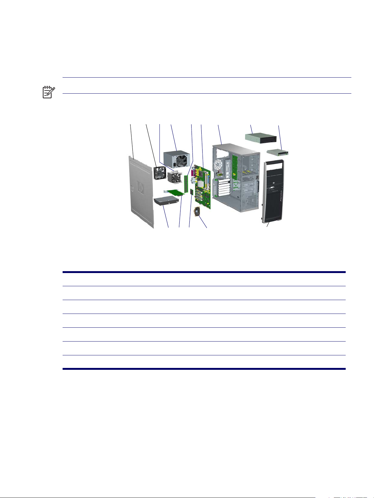
Exploded View
The following illustration shows an exploded view of the HP Workstation xw4200.
NOTE Drive configurations can vary.
1234 56 7 8 9
Figure 1-1 Exploded View
1 Access panel 8 Optical drive
2 System fan 9 Diskette drive
3 Processor heatsink 10 Bezel
4 Power supply 11 System speaker
5 Memory 12 Processor
6 System board 13 PCI Express Card
7 Chassis 14 Hard drive
1011121314
14 PRODUCT OVERVIEW

Front Panel Components
The following illustration shows a typical HP Workstation xw4200. Drive configurations might vary
depending on the configuration that was purchased.
1
2
7
3
4
8
9
10
5
6
11
12
13
14
Figure 1-2
1 Optical Drive* (optional) 6 Diskette Eject Button 11 Universal Serial Bus (USB) Ports
2 Optical Drive Activity Lights 7 Optical Drive Eject Button 12 Headphone Connector
3 5.25 inch drive bays 8 Power On Light 13 Microphone Connector
4 Diskette Drive (optional) 9 Power Button 14 IEEE-1394 Connector**
5 Diskette Drive Activity Light 10 Hard Drive Activity Light
Front Panel Components
Chapter 1
*An optical drive is a CD-ROM, CD-R/RW, DVD-ROM, DVD+R/RW, or CD-RW/DVD combo drive.
**IEEE-1394 is an optional feature. If the workstation was purchased without this option, then this connector will be covered.
PRODUCT FEATURES 15
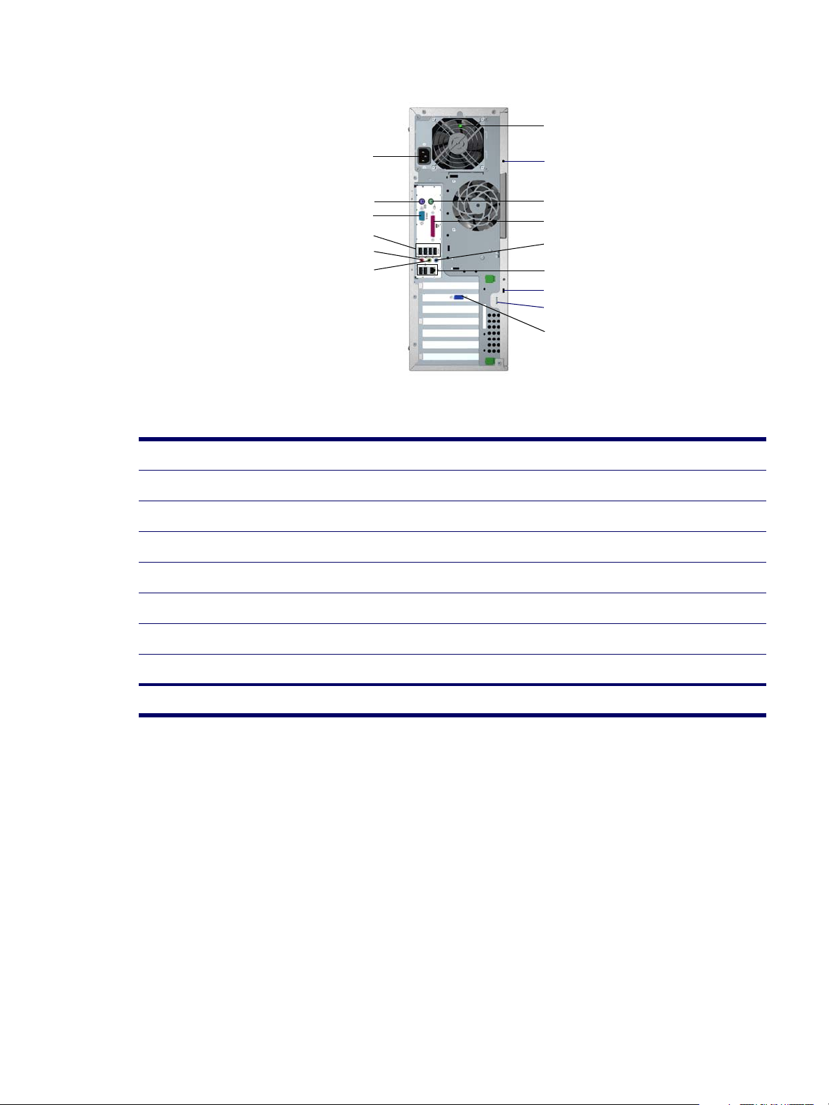
Rear Panel Components
7
1
2
3
4
5
6
8
9
10
11
12
13
14
15
Figure 1-3 Rear Panel Components
1 Power Cord Connector 9 PS/2 Mouse Connector (green)
2 PS/2 Keyboard Connector (purple) 10 Parallel Connector (burgundy)
3 Serial Connector (teal) 11 Audio Line-In Connector (light blue)
4 USB 12 RJ-45 Network Connector and two USB connectors
5 Microphone Connector (pink) 13 Cable Lock Slot
6 Audio Line-Out Connector (lime) 14 Padlock Loop
7 Built In Self Test (BIST) LED (green) 15 Graphics Adapter
8 Universal Chassis Clamp Lock
NOTE: The rear panel connectors are labeled with industry-standard icons to assist you in connecting your peripheral devices.
16 PRODUCT OVERVIEW
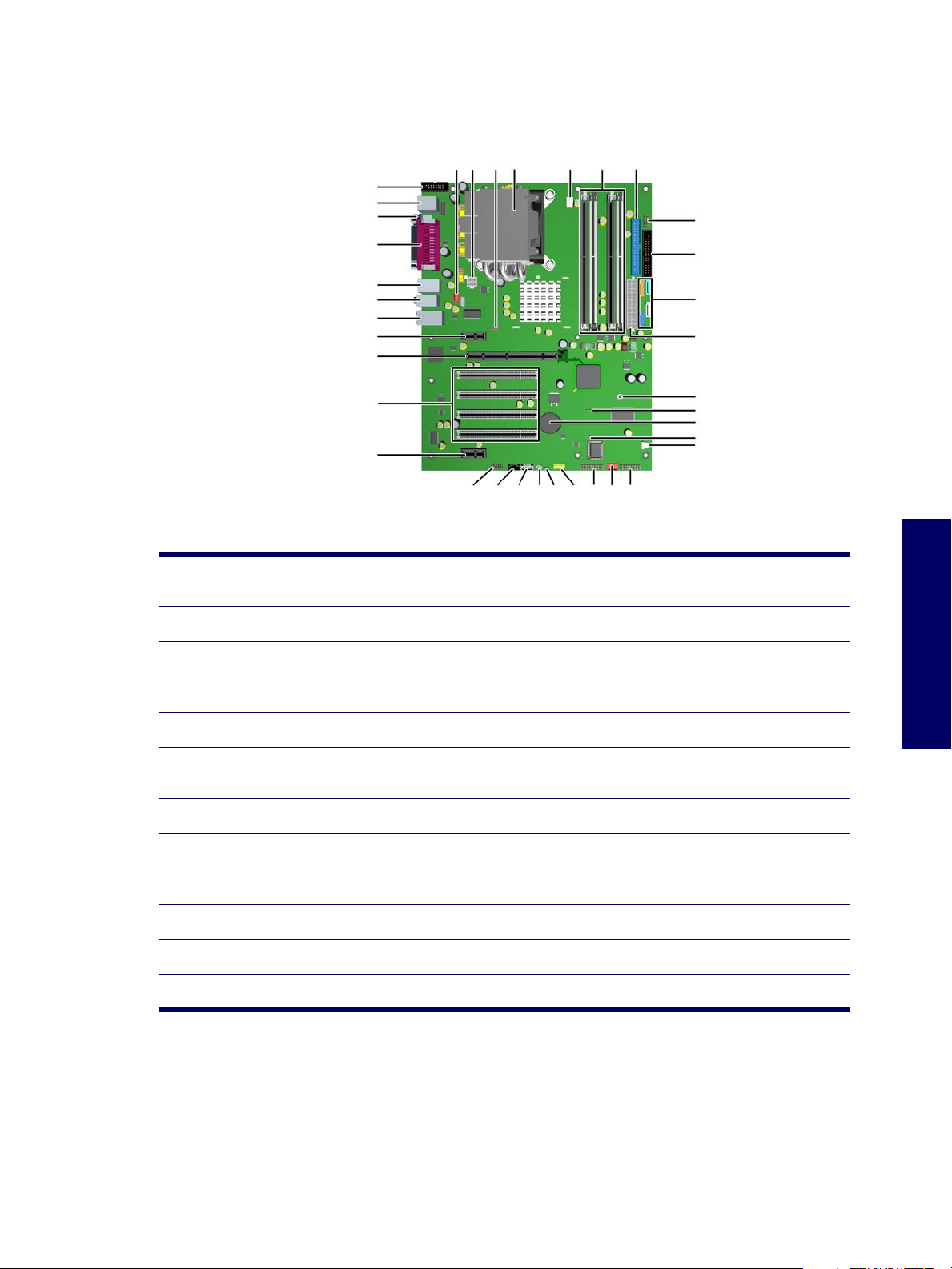
System Board Components
The following illustration shows the system board connectors and sockets on the HP Workstation
xw4200.
3433 32 31 30
3536
1
2
3
4
5
6
7
8
9
29
28
27
26
10
25
24
23
22
11
21
12 13 14 15 16 17 1819 20
Figure 1-4
1 Second serial port connector
(optional)
2 Keyboard/mouse 14 Auxiliary audio 26 Main power
3 Serial 15 Chassis speaker 27 Serial ATA
4 Parallel 16 Hard disk activity LED 28 Diskette drive
5 USB 17 Front USB 29 MultiBay
6 Audio 18 Trusted Platform Module
7 Network/USB 19 Front chassis fan (optional) 31 Memory modules sockets
8 PCI Express x1 20 Front control panel 32 Processor fan
System Board Components
13 CD-ROM audio 25 Clear CMOS button
30 IDE
connector
Chapter 1
9 PCI Express x16 21 Hood sensor 33 Processor
10 PCI 22 Boot block jumper 34 Solenoid hood lock
11 PCI Express x1 23 Battery 35 Processor power
12 Front audio 24 Password jumper 36 Rear chassis fan
PRODUCT FEATURES 17
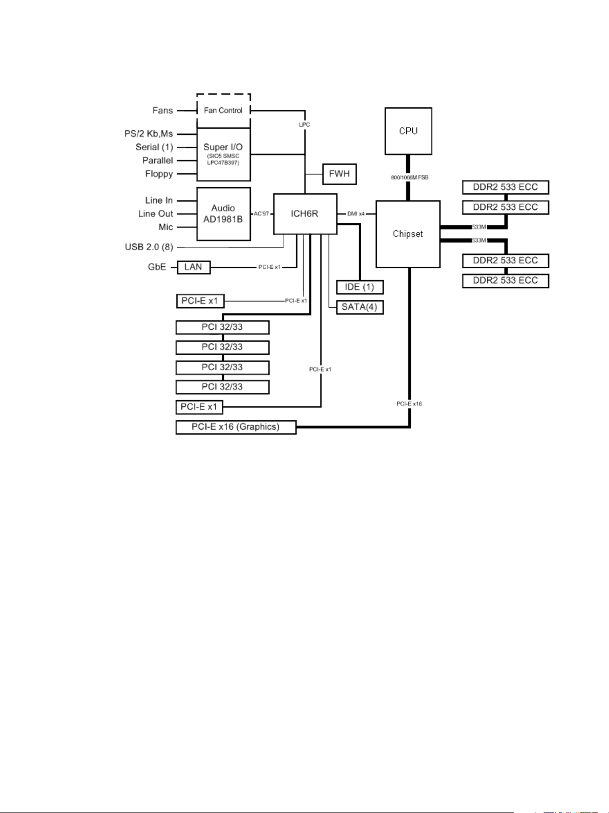
The following illustration shows the HP Workstation xw4200 block diagram.
Figure 1-5
HP Workstation xw4200 Block Diagram
18 PRODUCT OVERVIEW
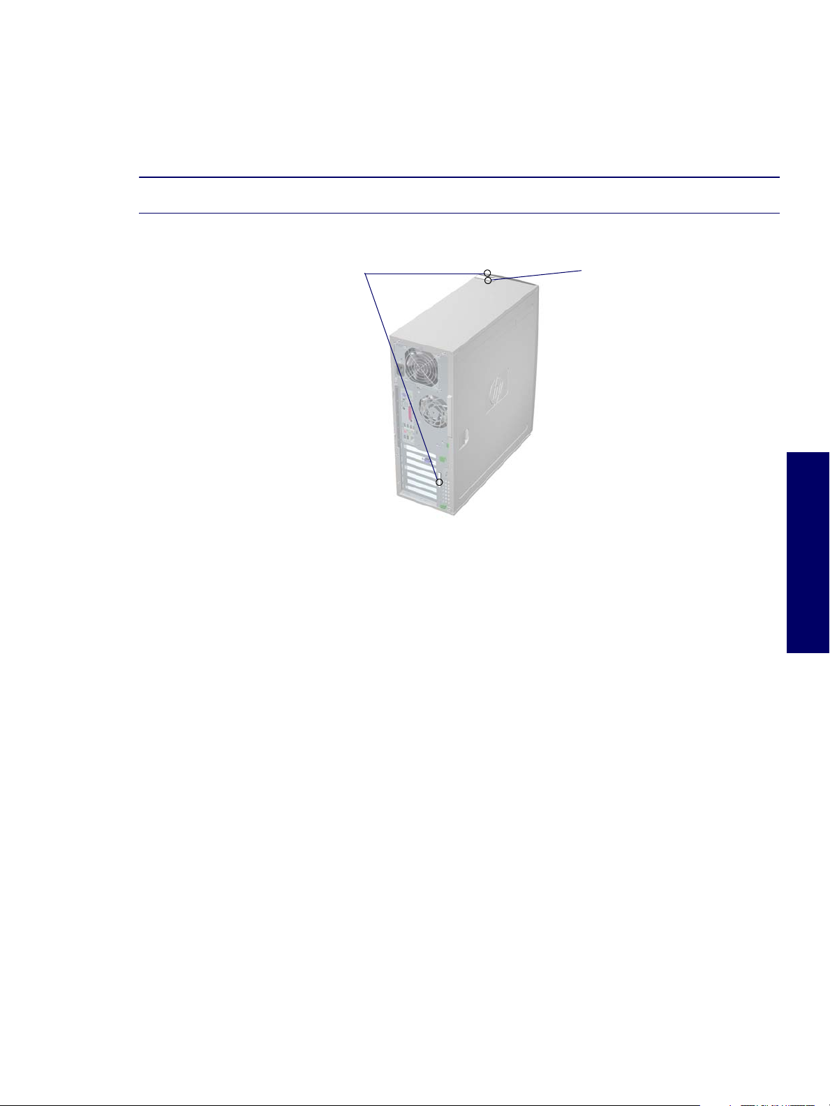
Serial Number and COA Label Location
Each workstation has two unique serial number labels 1 and a certificate of authentication (COA) label 2.
The serial number labels are located on the top (in a minitower configuration) of the unit and on the rear
panel. Keep this number available when contacting customer service for assistance. The COA label is
located on the top panel (in a minitower configuration).
NOTE The COA label is only if you have a Microsoft XP preinstalled system.
\
12
Chapter 1
PRODUCT FEATURES 19

Product Specifications
This section describes the physical, environmental, and graphical and PCI Express specifications for the
HP Workstation xw4200. For more specification information, visit http://www.hp.com
QuickSpecs for this product.
Physical Specifications
The following table shows the physical characteristics of the HP Workstation xw4200.
and search for the
Tabl e 1 -1
Weight 16 kg/35 lb (typical configuration)
Tower Dimensions 45.0 cm (17.7 in) high
Maximum Altitude
(Non-pressurized)
HP Workstation xw4200 Physical Characteristics
16.8 cm (6.6 in) wide
45.6 cm (17.9 in) deep
Operating: 3,000 m (10,000 ft)
Non-operating: 9,100 m (30,000 ft)
Environmental Specifications
The following table shows the HP Workstation xw4200 environmental specifications.
Tabl e 1 -2 HP Workstation xw4200 Environmental Specifications
Temperature Operating: 5 to 35°C (40 to 95°F)
Humidity Operating: 8 to 85%RH, non-condensing
Altitude Operating: 0 to 10,000 ft (3048m)
Non-operating: -40 to 60°C (-40 to 140°F)
Non-operating: 8 to 90%RH, non-condensing
Non-operating: 0 to 30,000 ft (9144m)
Shock Operating ½-sine: 40g, 2-3ms
Vibration Operating Random: 0.5g (rms), 5-300 Hz
20 PRODUCT OVERVIEW
Non-operating:
½-sine: 160 cm/s, 2-3ms, (~100g)·
square: 422 cm/s, 20g
Non-Operating:
random: 2.0 g (rms), 10-500 Hz·

Graphics and PCI Express Slot Power Specifications
Your workstation contains four PCI slots, two PCI Express x1 slots, and a single PCI Express x16 highend graphics slot. The following table describes the slots, card types, and maximum slot power.
Tabl e 1 -3
Slot# Card Type Slot Power (Maximum)
1 PCI Express x1 half-length 10 W*
2 PCI Express x16 graphics 75 W*
3-6 PCI 25 W*
7 PCI Express x1 full-length 25 W*
* In addition to these slot power specifications, the overall power consumption of the system (including I/O
cards, processor, and memory) must not exceed the maximum ratings of the system power supply.
HP Workstation xw4200 Graphics and PCI Express Slot Power Specifications
NOTE For hardware specifications of other system components, such as graphics cards or optical
drives, visit the Web site of the specific manufacturer.
Chapter 1
PRODUCT SPECIFICATIONS 21

Power Supply and Cooling
The following table shows the power supply specifications of the HP Workstation xw4200.
Tabl e 1 -4
Full Ranging Input (No Line Select Switch) Yes
Active Power Factor Correction (APFC)
(Input Current is nearly 1/2 a non-APFC PS)
Passive Power Factor Correction (PFC) No
Operating Voltage Range 90 to 264 VAC/118 VAC
Rated Voltage Range 100 to 240 VAC
Rated Line Frequency 50 to 60 Hz/400 Hz
Operating Line Frequency Range 47 to 66 Hz/393 to 407 Hz
Rated Input Current 6.4A/6.4A
Maximum Rated Power 410 W
Heat Dissipation Typical 737.1 btu/hr
Power Supply Fan 92mm variable speed
Power Supply Dimensions 9.76 cm (3.843 in) wide
HP Workstation xw4200 Power Supply Specifications
Yes
Maximum 2152.8 (410W)
15 cm (5.906 in) high
15.371 cm (6.052 in) deep
ENERGY STAR Compliant Yes
FEMP Standby Power Compliant
(<2W in S5–Power Off)
Power Consumption in ES Mode–Suspend to RAM (S3)
(Instantly Available PC)
Built-in Self Test LED Yes
Surge Tolerant Full Ranging Power Supply Withstands power surges up to 2000 V
No
2.5 W
22 PRODUCT OVERVIEW

Power Consumption and Cooling
The following table shows the power consumption for a typical configuration based on primary power
consumptions:
One processor (1 x 3.4 GHz Pentium 4 Processor with HT Technology)
One GB memory (2 x 512 MB)
Two hard drives (2 x SATA 40 GB)
CD-ROM drive
PCI-Express Graphics Card (Quadro FX 1300)
One diskette
Monitor
Tabl e 1 -5
Input Power Consumption 120 VAC/60Hz
Typical operating mode (system busy) 216 W/737.1 btu/hr
Windows XP Idle 138 W/470.9 btu/hr
Standby mode (S3) 2.5 W/8.53 btu/hr
Hibernate mode (S4) 2.1 W/7.166 btu/hr
Power Off (S5) 7.166 btu/hr
HP Workstation xw4200 Power Consumption and Cooling
NOTE When you turn off your workstation with the power button on the front panel, the power
consumption falls below 10 W. To reach zero power consumption, either unplug the workstation from the
power outlet or use a power strip with a switch. However, removing all power to the workstation might
reduce the life of the real-time clock battery.
For more information on power-saving features, refer to your operating system documentation.
System Fans and Airflow
Chapter 1
The workstation includes a rear system fan, one processor heatsink fan, plus an optional front system
fan.
Resetting the Power Supply
If an overload triggers the power supply overload protection, all power is immediately cut. To reset the
power supply unit:
1 Disconnect the power cord.
2 Determine what caused the overload, and fix the problem.
3 Reconnect the power cord and reboot the workstation.
POWER SUPPLY AND COOLING 23

ENERGY STAR
The ENERGY STAR® program, a government-backed initiative, promotes energy efficiency by
identifying ways to reduce energy consumption. Select HP workstations participate in the ENERGY
STAR program.
NOTE ENERGY STAR is not supported on Linux-based workstations.
For those workstations that support ENERGY STAR and have it enabled, the power management
features will be set as follows:
Monitor—goes into Sleep mode after 20 minutes of inactivity.
System—goes into Standby mode after 20 minutes of inactivity.
Hard Drive—goes into Power Savings mode after the system goes into Standby mode.
NOTE If you must restore the operating system, reset the ENERGY STAR settings (if applicable).
To verify the factory default power settings for your product:
From the Windows 2000 or Windows XP Classic Start menu, select Start>Settings>Control
Panel>Power Options.
From the Windows XP standard Start menu, select Start>Control Panel>Performance and
Maintenance>Power Options.
24 PRODUCT OVERVIEW

ENERGY STAR Compliance
HP products purchased with the ENERGY STAR configuration are compliant with the U.S.
Environmental Protection Agency (EPA) ENERGY STAR Computers Program. The EPA ENERGY STAR
configuration does not imply endorsement by the EPA. As an ENERGY STAR Partner, HP has
determined that products with the ENERGY STAR configuration meet the ENERGY STAR guidelines
for energy efficiency.
The ENERGY STAR Computers Program was created by the EPA to promote energy efficiency and
reduce air pollution through more energy-efficient equipment in homes, offices, and factories. HP
products achieve this by reducing the power consumption when not being used.
ENERGY STAR on HP Workstations uses ACPI power management. The system can wake as a result
of a user action (keyboard or mouse) or from the network or a modem.
The Power Management feature, when used in conjunction with an external ENERGY STAR-compliant
monitor, will support the power-down features of the monitor. The Power Management feature allows an
external monitor to go into low-power mode when the energy save timeout occurs.
CAUTION Using the Energy Save Monitor feature with non-ENERGY STAR compliant monitors might
cause video distortion when the Energy Save timeout occurs.
Hyper-Threading Technology
Hyper-Threading Technology is a high-performance technology, developed by Intel®, that enables a
single processor to execute multiple threads of instructions simultaneously. Hyper-Threading Technology
enables the processor to utilize its execution resources more efficiently, delivering performance
increases and improving user productivity. Not all systems benefit from the Hyper-Threading Technology.
To see if Hyper-Threading Technology can benefit you, test your system by turning the feature on.
Computer Setup (F10) can be used to turn this feature on. To do this, run F10 Setup during boot up and
select Advanced>Device Options>Hyper-Threading, and enable the Hyper-Threading Technology.
NOTE If your workstation does not support Hyper-Threading Technology, the Hyper-Threading menu
item will not be available on the Computer Setup menu.
NOTE The Hyper-Threading Technology is recommended for use with Windows XP systems. This
technology is detected by the system and is turned on in the operating system after it is enabled in the
system BIOS.
Chapter 1
NOTE Red Hat Enterprise Linux WS 3 supports Hyper-Threading Technology. An SMP-capable kernel
must be installed on your system before this technology can be utilized.
For more information about the Hyper-Threading Technology, visit the Intel Web site at
http://www.intel.com
.
HYPER-THREADING TECHNOLOGY 25

26 PRODUCT OVERVIEW

Chapter 2 Installing or Restoring the Operating System
This chapter discusses installation and restoration of the operating system. This chapter includes the
following sections:
“Installing the Operating System and Software” on page 28
“Restoring the Operating System” on page 31
“Protecting the Software” on page 31
“Ordering Backup Software” on page 32
If the workstation was shipped with a preinstalled OS, it is configured automatically the first time the
workstation is turned on.
CAUTION Do not add optional hardware devices to your workstation until the operating system is
successfully installed. Doing so can cause errors and might prevent the operating system from installing
properly.
CAUTION When the automatic installation has begun, DO NOT TURN OFF THE WORKSTATION
UNTIL THE PROCESS IS COMPLETE. Turning off the workstation during the installation process might
damage the software that runs the workstation.
Chapter 2
27

Installing the Operating System and Software
The following section discusses the operating system and HP software installation procedures.
Microsoft Windows XP Professional
The first time you turn on your workstation, you will be prompted to select a language for the operating
system. After selecting the language, read and follow the on-screen instructions to complete the
installation of the operating system. This takes approximately 10 minutes, depending on the system
hardware configuration. During the process, do not turn off your workstation unless you are directed to
do so.
Installing or Upgrading Device Drivers
To install hardware devices, such as a printer, a display adapter, or network adapter after the operating
system installation is completed, make sure that the operating system has access to the appropriate
software drivers for the devices. Device drivers are usually provided on a CD supplied with the peripheral
device.
Some existing peripheral devices might not have been shipped with drivers developed for Windows XP.
To locate the most current device drivers, visit http://www.hp.com
Creating a Restore Diskette
To create a restore diskette for Windows XP, go to Start>All Programs>Accessories>System
Tools>System Restore, and follow the on-screen instructions.
.
Linux-Preinstalled Workstations
If you have a Linux-preinstalled workstation, follow the instructions in this section to set up your OS and
software.
After the boot process completes, you can view additional HP Linux documentation by simply opening
your Internet browser (the browser is automatically set to use the local HP documentation page as its
default). You can also access Linux Web links for Red Hat (Internet access required) by using your
Internet browser.
NOTE For additional information concerning the setup of Linux-preinstalled or Linux-enabled
workstations, refer to the
linux_user_manual.
For more information about HP and Linux, visit http://www.hp.com/linux.
Starting Up the Linux Operating System
The first time the workstation is booted, the Red Hat First Boot utility displays. This program enables you
to enter your password, network, graphics, time, and keyboard settings for your workstation.
HP User Manual for Linux
, located at http://www.hp.com/support/
CAUTION When the automatic installation has begun, DO NOT TURN OFF THE WORKSTATION
UNTIL THE PROCESS IS COMPLETE. Turning off the workstation during the installation process might
damage the software that runs the workstation or prevent its proper installation.
28 INSTALLING OR RESTORING THE OPERATING SYSTEM

NOTE When you enable the YPBind feature in the Network tab of the Linux Setup Tool, you might get a
blank screen for about 15–30 seconds after you have selected and saved all of your settings and have
exited the utility. This is normal. The boot process continues its execution after the screen returns.
Restoring the Linux Operating System
NOTE To restore the Linux OS, the HP Driver CD and Red Hat box set are required.
Download the latest HP Driver CD to get any new enhancements.
NOTE Linux does not support mixed hard disk drive types for manufacturing preload. When restoring
the operating system, mixed hard disk drive types can be handled with the restoring media.
DOWNLOADING THE LATEST HP DRIVER CD
To download the latest HP Driver CD:
1 Download the ISO image to a local hard drive from the HP support Web site for the appropriate
workstation platform (such as http://www.hp.com/support/xw4200
).
a Click the download drivers and software link.
b Select the Linux OS that matches your box set.
c Select the latest version from the Utility Tools section.
d Download and unpack it (tar zxvf
2 Copy the ISO image to CD-R bootable media. On another Linux workstation, use the cdrecord utility.
Identify the device address for the CD burner (cdrecord --scanbus).
The default is usually 2, 0, 0.
Example:
cdrecord -v -eject dev=2,0,0 CD0_golden.iso
INSTALLING WITH THE HP DRIVER CD
To install with the HP Driver CD:
1 Boot the workstation from the Red Hat box set Binary CD 1.
2 Insert the Linux operating system CDs from the Red Hat box set as prompted.
3 Continue following the prompts until the operating system is successfully installed.
4 Configure the X server to start on reboot.
filename
.tgz).
Chapter 2
5 Reboot the workstation.
6 Follow the prompts to set up your system with the Red Hat First Boot utility.
7 When prompted in First Boot to add additional CDs, insert the HP Driver CD into the CD-ROM tray of
the workstation.
INSTALLING THE OPERATING SYSTEM AND SOFTWARE 29

8 Click Install next to “Additional CDs.”
The HP Driver CD window opens.
9 Click Press to begin install...
10 When the install is done, you will have two options, “Reboot now...” on the left side and “Press to
continue, reboot later...” on the right side. Click Reboot now...
Upgrading Device Drivers
If you must upgrade a Linux device driver, visit the HP Web site at http://www.hp.com/go/
workstationsupport.
Linux-Enabled Workstations
Linux-enabled workstations are not pre-installed with Linux. They require the HP Installer Kit for Linux
and the purchase of a Red Hat box set. The Installer kit includes the HP CDs necessary to complete the
installation of all versions of the Red Hat box set which have been verified to work on HP workstation
hardware.
Verifying Hardware Compatibility
To see which Linux versions have been verified to work on HP workstation hardware:
1 Go to http://www.hp.com/support/workstation_manuals
2 Select your HP workstation model.
3 Click the Hardware Support Matrix for Linux link.
.
Installing the Linux Operating System
To install the Linux operating system on your Linux-enabled system:
1 Follow the instructions for “Restoring the Linux Operating System” in the previous section.
2 Follow the instructions for “Starting Up the Linux Operating System” in the previous section.
NOTE For more information concerning the setup of Linux-preinstalled or Linux-enabled workstations,
refer to the
For more information about HP and Linux, visit http://www.hp.com/linux
HP User Manual for Linux
, located at http://www.hp.com/support/linux_user_manual.
.
Upgrading Device Drivers
If you must upgrade a Linux device driver, visit the HP Web site at http://www.hp.com/go/
workstationsupport.
30 INSTALLING OR RESTORING THE OPERATING SYSTEM

HP Software
The following HP software will also be installed the first time the workstation is turned on:
Computer Setup (F10) Utilities and diagnostic features
HP Support Software including device drivers
HP Client Manager Software (available for download from http://www.hp.com/go/EasyDeploy
System Software Manager (available for download from http://www.hp.com/go/ssm
Power Management Setup with energy saver features (not supported for Linux)
Security Management tools
Software Support Management tools
Certain drivers and utilities are available only in selected languages. You can obtain the latest version of
these files, in English and selected other languages, in one of the following ways:
Support Software CD
HP Web site at http://www.hp.com
Restore Plus!
HP Workstations Driver for Red Hat Enterprise Linux 3
workstations
NOTE Additional HP software might be required in certain situations.
CD, which is supplied with Windows-based workstations
CD, which is supplied with Linux-based
)
)
Restoring the Operating System
Restore the original Microsoft Windows XP Professional operating and factory-installed software by
using the
instructions provided with the
For more information about restoring the Linux OS or software, see “Restoring the Linux Operating
System” on page 29.
Restore Plus!
CD and the OS CD that came with the workstation. Carefully read and follow the
Restore Plus!
CD.
Protecting the Software
To protect software from loss or damage, you should keep a backup copy of all system software,
applications, and related files stored on the hard drive. Refer to the operating system or backup utility
documentation for instructions on making backup copies of data files.
Chapter 2
RESTORING THE OPERATING SYSTEM 31

Ordering Backup Software
All software that shipped with the workstation, including the
as a single set, or you can order the various software packages separately.
NOTE Before calling HP to order the software, be sure to have the serial number of the workstation
available. This number is necessary for all diskette orders. See the “Serial Number and COA Label
Location” on page 19 for the location of the serial number on the workstation.
Restore Plus!
CD, can be ordered from HP
32 INSTALLING OR RESTORING THE OPERATING SYSTEM

Chapter 3 System Management
This chapter discusses the various tools and utilities that allow for the system management of the HP
Workstation xw4200. This chapter includes the following sections:
“Computer Setup (F10)” on page 34
“Desktop Management” on page 44
Chapter 3
33

Computer Setup (F10)
The Computer Setup (F10) utilities enable you to perform the following tasks:
Change factory default settings and to set or change the system configuration, which might be
necessary when you add or remove hardware.
Determine if all of the devices installed on the workstation are recognized by the system and
functioning properly.
Determine information about the operating environment of the workstation.
Solve system configuration errors detected but not automatically fixed during the Power-On Self-Test
(POST).
Establish and manage passwords and other security features.
Establish and manage energy-saving timeouts (not supported for Linux platforms).
Modify or restore factory default settings.
Set the system date and time.
Set, view, change, or verify the system configuration including settings for processor, graphics,
memory, audio, storage, communications, and input devices.
Modify the boot order of bootable devices, such as hard drives, diskette drives, optical drives, or LS-
120 drives.
Configure the boot priority of SATA, IDE (ATA) and SCSI hard drive controllers.
Enable Quick Boot which is faster than Full Boot, but does not run all of the diagnostic tests run
during a Full Boot. You can set your system to:
always Quick Boot (default)
periodically Full Boot (from every 1–30 days)
always Full Boot
Enable or disable Network Server Mode, which allows the workstation to boot the operating system
when the power-on password is enabled with or without a keyboard or mouse attached. When
attached to the system, the keyboard and mouse remain locked until the power-on password is
entered.
Select POST Messages Enabled or Disabled to change the display status of POST messages. POST
Messages Disabled suppresses most POST messages, such as memory count, product name, and
other non-error text messages. If a POST error occurs, the error is displayed regardless of the mode
selected. To manually switch to POST Messages Enabled during POST, press any key (except F1
through F12).
Establish an Ownership Tag, the text of which is displayed each time the system is turned on or
restarted.
Enter the Asset Tag or property identification number assigned by your company to this workstation.
Enable power-on password prompting during system restarts (warm boots) as well as during power-
on.
Secure the integrated I/O functionality, including the serial, USB, or parallel ports, audio, or
embedded NIC, so that they cannot be used until they are unsecured.
Enable or disable Master Boot Record (MBR) Security.
34 SYSTEM MANAGEMENT

Enable or disable removable media boot ability.
Enable or disable removable media write ability (when supported by hardware).
Replicate your system setup by saving system configuration information on diskette and restoring it
on one or more workstations.
Execute self-tests on a specified SATA or IDE (ATA) hard drive (when supported by the drive).
NOTE All features identified in this chapter might not be available on all HP products.
BIOS ROM
The Basic Input/Output System (BIOS) of the workstation is a collection of machine language programs
stored as firmware in read-only memory (ROM). The BIOS ROM includes such functions as POST, PCI
device initialization, Plug 'n Play support, power management activities, and the Setup utility. The
firmware contained in the BIOS ROM supports the following systems and specifications:
Microsoft WHQL
Alert-On-LAN (AOL) and Wake-On-LAN (WOL)
ACPI 1.0 and OnNow
SMBIOS 2.3.5
PC98/99/00 and NetPC
PXE boot ROM for the integrated LAN controller
BIOS Boot Specification 1.01
Enhanced Disk Drive Specification 3.0
“El Torito” Bootable CD-ROM Format Specification 1.0
ATAPI Removable Media Device BIOS Specification 1.0
MPS Specification 1.4 (for booting Linux SMP)
The BIOS ROM is a 512-KB Firmware Hub (or Firmware Hub-compatible) part. The runtime portion of
the BIOS resides in a 128-K block from E0000h to FFFFFh.
COMPUTER SETUP (F10) 35
Chapter 3

Using Computer Setup (F10)
Computer Setup can be accessed only by turning on the workstation or restarting the system. To access
the Computer Setup Utilities menu:
1 Turn on or restart the workstation. If you are in Windows, click Start>Shut Down>Restart the
Computer.
2 Wait for the
F10=Setup prompt to appear on the lower right corner of the screen. Once you see the
prompt, press the F10 key to enter the F10 setup utility.
NOTE If you do not press the F10 key at the appropriate time, you must try again. Turn the workstation
off, then on again, and press the F10 key again to access the utility.
3 Select your language from the list and press Enter. A choice of four headings appears in the
Computer Setup Utilities menu: File, Storage, Security, and Advanced.
4 Use the arrow (left and right) keys to select the appropriate heading. Use the arrow (up and down)
keys to select the option you want, then press Enter.
5 To apply and save changes, select File>Save Changes and Exit.
If you have made changes that you do not want applied, select Ignore Changes and Exit.
To reset to factory settings, select Set Defaults and Exit. This option will restore the original
factory system defaults.
CAUTION Do NOT turn the workstation power OFF while the ROM is saving your Computer Setup F10
changes because the CMOS could become corrupted. It is safe to turn off all power to the workstation
after you exit the F10 Setup screen.
NOTE This menu can change with new firmware releases, so it might be consistent with what is
presented in the following table.
36 SYSTEM MANAGEMENT

Tab l e 3-1 Computer Setup Menu
Heading Option Description
File System Information Lists product name, processor type/speed/stepping, cache size (L1/L2), system ROM family
and version, installed memory size, chassis serial number, integrated MAC for enabled or
embedded NIC (if applicable), and asset tracking number.
About Displays copyright information.
Set Time and Date Allows you to set system time and date.
Replicated Setup Save to Removable Media
Default Setup Save Current Settings as Default
Apply Defaults and Exit Restores factory default settings which includes clearing any established passwords.
Ignore Changes and Exit Exits Computer Setup without applying or saving any changes.
Save Changes and Exit Saves changes to system configuration and exits Computer Setup.
Saves system configuration, including CMOS, to a formatted blank 1.44-MB diskette in file
CPQsetup.txt.
Restore to Removable Media
Restores system configuration from a diskette.
Saves the current settings as default settings for the next operation.
Restore Factory Settings as Default
Restores the factory settings as the default settings for the next operation.
COMPUTER SETUP (F10) 37
Chapter 3

Tab l e 3-1 Computer Setup Menu (Continued)
Heading Option Description
Storage Device Configuration Lists all installed non-SCSI storage devices.
SCSI storage drives will not be listed in Computer Setup (F10).
When a device is selected, detailed information and options are displayed. The following
options might be presented:
Diskette Type
Identifies the highest capacity media type accepted by the diskette drive. Options are 3.5" 1.44
MB, 5.25" 1.2 MB, and Not Installed.
Drive Emulation
Allows you to select a drive emulation type for a storage device. (For example, a Zip drive can
be made bootable by selecting disk emulation.)
Drive Type Emulation Options
ATAPI Zip drive None (treated as Other).
IDE Hard disk None (treated as Other).
Legacy diskette No emulation options available.
IDE CD-ROM No emulation options available.
ATAPI LS-120 No emulation options available.
Transfer Mode
Specifies the active data transfer mode. Options (subject to device capabilities) are PIO 0, Max
PIO, Enhanced DMA, Ultra DMA 0, and Max UDMA.
(for legacy diskette drives only)
(IDE devices only)
Diskette (treated as diskette drive).
Disk (treated as hard drive).
Disk (treated as hard drive).
(IDE devices only)
Translation Mode
Lets you select the translation mode to be used for the device. This enables the BIOS to
access disks partitioned and formatted on other systems and may be necessary for users of
older versions of UNIX (for example, SCO UNIX version 3.2). Options are Bit-Shift, LBA
Assisted, User, and None.
CAUTION: A new Automatic option has been added to allow for BIOS to automatically
determine the translation mode used to configure a previously formatted IDE, SATA, or USB
mass storage device. This prevents you from having to know how the mass storage device was
previously formatted.
Ordinarily, the translation mode selected automatically by the BIOS should not be changed. If
the selected translation mode is not compatible with the translation mode that was active when
the disk was partitioned and formatted, the data on the disk will be inaccessible.
Translation Parameters
Allows you to specify the parameters (logical cylinders, heads, and sectors per track) used by
the BIOS to translate disk I/O requests (from the operating system or an application) into terms
the hard drive can accept. Logical cylinders cannot exceed 1024. The number of heads cannot
exceed 256. The number of sectors per track cannot exceed 63. These fields are only visible
and changeable when the drive translation mode is set to User.
Multisector Transfers
Specifies how many sectors are transferred per multi-sector PIO operation. Options (subject to
device capabilities) are Disabled, 8, and 16.
(IDE disks only)
(IDE disks only)
(IDE disks only)
38 SYSTEM MANAGEMENT

Tab l e 3-1 Computer Setup Menu (Continued)
Heading Option Description
Storage
(continued)
Options Removable Media Boot
Enables/disables ability to boot the system from removable media.
Legacy Diskette Write
Enables/disables ability to write data to removable media.
NOTE: This feature applies only to legacy diskette, (IDE/ATA) LS-120 Superdisk, (IDE/ATA)
LS-240 Superdisk, and (IDE/ATA) PD-optical drives.
NOTE: After saving changes to Removable Media Boot, the workstation will restart. Manually,
turn the workstation off, then on.
BIOS DMA Data Transfers
Allows you to enable or disable the BIOS use of DMA for IDE data transfers.
IDE Controller
Allows you to enable or disable the primary IDE/ATA controller.
SATA Emulation
Enables the SATA to emulate the RAID controller, combined controllers, or a separate
controller.
SATA Primary Controller
Allows you to disable the SATA primary controller ports.
SATA Secondary Controller
Allows you to disable the SATA secondary controller ports.
Diskette MBR Validation
Allows you to enable or disable strict validation of the diskette MBR.
NOTE: If you use a bootable diskette image that you know to be valid, and it does not boot with
Diskette MBR Validation enabled, you might need to disable this option to use the diskette.
IDE DPS Self-Test Allows you to execute self-tests on IDE hard drives capable of performing the Drive Protection
Controller Order* Allows you to specify the order of the attached hard drive controllers. The first hard drive
Boot Order Allows you to configure the boot, diskette drive, and hard drive orders by physically reordering
*Available on select models.
System (DPS) self-tests.
NOTE: This selection will only appear when at least one drive capable of performing the IDE
DPS self-tests is attached to the system.
controller in the order will have priority in the boot sequence and will be recognized as drive C
(if any devices are attached).
NOTE: The selection will not appear if all hard drives are attached to the embedded IDE
controllers.
the menu entries. Each device on the list can be individually excluded from or included for
consideration as a bootable operating system source.
NOTE: MS-DOS drive lettering assignments might not apply after a non-MS-DOS operating
system has started.
Shortcut to Temporarily Override Boot Order
To boot one time from a device other than the default device specified in Boot Order, restart
the workstation and press F9 when the F10=Setup message appears on the screen. After
POST is completed, a list of bootable devices is displayed. Use the arrow keys to select the
preferred bootable device and press Enter. The workstation then boots from the selected nondefault device for this one time.
COMPUTER SETUP (F10) 39
Chapter 3

Tab l e 3-1 Computer Setup Menu (Continued)
Heading Option Description
Security Setup Password Allows you to set and enables setup (administrator) password.
NOTE: If the setup password is set, it is required to change Computer Setup options, flash the
ROM, and make changes to certain Plug ‘n Play settings under Windows.
Power-On Password Allows you to set and enable power-on password.
Device Security* Enables/disables serial ports A and B, parallel port, front USB ports, all USB ports, system
Network Service Boot Enables/disables the workstation’s ability to boot from an operating system installed on a
Password Options (This
selection will appear
only if a power-on
password is set.)
Hood sensor* Allows you to enable/disable solenoid hood (Smart Cover) lock.
DriveLock* Allows you to assign or modify a master or user password for certain hard drives. When
Master Boot Record
Security*
audio, network controllers (some models), and SCSI controllers (some models).
network server. (Feature available on NIC models only; the network controller must reside on
the PCI bus or be embedded on the system board.)
Allows you to specify whether the password is required for warm boot (CTRL+ALT+DEL).
NOTE:
Notify User
removed.
if the sensor detects that the cover has been removed.
This feature is supported on select models only.
enabled, the user is prompted to provide one of the DriveLock passwords during POST. If
neither is successfully entered, the hard drive will remain inaccessible until one of the
passwords is successfully provided during a subsequent cold-boot sequence.
This selection will only appear when at least one drive that supports the DriveLock feature is
attached to the system.
Allows you to enable or disable MBR Security.
When enabled, the BIOS rejects all requests to write to the MBR on the current bootable disk.
Each time the workstation is powered on or rebooted, the BIOS compares the MBR of the
bootable disk to the previously saved MBR. If changes are detected, you are given the option
of saving the MBR on the current bootable disk, restoring the previously saved MBR, or
disabling MBR security. You must know the setup password if one is set.
NOTE: Disable MBR Security before intentionally changing the formatting or partitioning of the
current bootable disk. Several disk utilities (such as FDISK and FORMAT) attempt to update
the MBR.
Setup Password
alerts the user that the sensor has detected that the cover has been
requires that the setup password be entered to boot the workstation
Save Master Boot
Record*
System IDs Allows you to set:
*Available on select models
40 SYSTEM MANAGEMENT
If MBR Security is enabled and disk accesses are being serviced by the BIOS, write requests
to the MBR are rejected, causing the utilities to report errors.
If MBR Security is enabled and disk accesses are being serviced by the operating system, any
MBR change will be detected by the BIOS during the next reboot, and an MBR Security
warning message will be displayed.
Saves a backup copy of the Master Boot Record of the current bootable disk.
NOTE: Only appears if MBR Security is enabled.
- Asset tag (18-byte identifier) and ownership Tag (80-byte identifier displayed during POST).
- Chassis serial number or Universal Unique Identifier (UUID) number. The UUID can only be
updated if the current chassis serial number is invalid. (These ID numbers are normally set in
the factory and are used to uniquely identify the system.)
- Keyboard locale setting (for example, English or German) for System ID entry.

Tab l e 3-1 Computer Setup Menu (Continued)
Heading Option Description
Security
(continued)
Power OS Power Management Allows you to enable PCI Express ASPM support.
Restore Master Boot
Record*
Smarter Allows you to use Smarter authentication for the Pre-Boot process.
Embedded Security
Device
Device Security SMBUS Controller was added to embedded devices capable of being hidden or available
Thermal Allows you set the fan idle mode.
Restores the backup Master Boot Record to the current bootable disk.
NOTE: Only appears if all of the following conditions are true:
- MBR Security is enabled.
- A backup copy of the MBR has been previously saved.
- The current bootable disk is the same disk from which the backup copy of the MBR was
saved.
NOTE: Restoring a previously saved MBR after a disk utility or operating system has modified
the MBR might cause the data on the disk to become inaccessible. Only restore a previously
saved MBR if you are confident that the current bootable disk’s MBR has been corrupted or
infected with a virus.
Embedded Security Device
Allows you to activate the Trusted Platform Module.
Setup password must be established before this menu item can be selected.
Reset to Factory Settings
Allows you to clear all encryption keys stored into the Trusted Platform Module.
Setup password must be established before this menu item can be selected.
during a refresh of the BIOS.
*Available on select models.
COMPUTER SETUP (F10) 41
Chapter 3

Tab l e 3-1 Computer Setup Menu (Continued)
Heading Option Description
Advanced** Power-On Options Allows you to set:
- POST mode (QuickBoot, FullBoot, or FullBoot every 1–30 days).
- POST messages (enable/disable).
- Safe POST* (enable/disable). Enabling this feature allows the ROM to monitor add-in cards
during boot. If an add-in card does not work or initialize correctly, then on the next boot all cards
will be skipped during POST.
- F9 prompt (enable/disable). Enabling this feature will display the text F9=Boot Menu during
POST. Disabling this feature prevents the text from being displayed but pressing F9 will still
access the Shortcut Boot (Order) Menu screen. Refer to Storage>Boot Order for more
information.
- F10 prompt (enable/disable). Enabling this feature will display the text F10=Setup during
POST. Disabling this feature prevents the text from being displayed but pressing F10 will
still access the Setup screen.
- F12 prompt (enable/disable). Enabling this feature will display the text F12=Network
Service Boot during POST. Disabling this feature prevents the text from being displayed
but pressing F12 will still force the system to attempt booting from the network.
- Option ROM* prompt (enable/disable). Enabling this feature will cause the system to display a
message before loading options ROMs.
- Remote wakeup boot source (remote server/local hard drive).
- Fan Idle Mode: Allows you set the fan idle mode.
- After Power Loss (off/on/previous state): After power loss, if you connect your workstation to
an electric power strip and would like to turn on power to the workstation using the switch on
the power strip, set this option to ON. The previous state will set the power loss setting to
whatever the unit status was before the power loss.
- If you turn off power to your workstation using the switch on a power strip, you will not be able
to use the suspend/sleep feature or the Remote Management features.
- POST Delay (in seconds) (enable/disable). Enabling this feature will add a user-specified
delay to the POST process. This delay is sometimes needed for hard disks on some PCI cards
that spin up very slowly; so slowly that they are not ready to boot by the time POST is finished.
The POST delay also gives you more time to select F10 to enter Computer Setup (F10).
- I/O APIC Mode (enable/disable). Enabling this feature will allow Microsoft Windows Operating
system to run optimally. This feature must be disabled for certain non-Microsoft Operating
Systems to work properly.
- ACPI/USB Buffers @ Top of Memory (enable/disable). Enabling this feature places USB
memory buffers at the top of memory. The advantage of remapping is that it allows space in the
DOS Compatibility Hole range, below 1-MB, to be made available for additional PCI plug-in
cards that need option ROM space.
BIOS Power-On Allows you to select week days and a specific time to automatically power the unit on from the
power-off state.
Onboard Devices Allows you to set resources for or disable onboard system devices (serial port, parallel port, or
PCI Devices Lists currently installed PCI devices and their IRQ settings.
Bus Options* Allows you to enable or disable:
*Available on select models.
**These options should be used by advanced users only.
diskette controller).
Allows you to reconfigure IRQ settings for these devices or to disable them entirely. These
settings have no effect under an APIC-based operating system.
- PCI bus mastering, which allows a PCI device to take control of the PCI bus.
- PCI VGA palette snooping, which sets the VGA palette snooping bit in PCI configuration
space; only needed when more than one graphics controller is installed.
- PCI SERR# generation.
- ECC support allows hardware-based error correction for ECC-capable memories.
42 SYSTEM MANAGEMENT

Tab l e 3-1 Computer Setup Menu (Continued)
Heading Option Description
Advanced**
(continued)
Device options Allows you to set:
- Printer mode (bi-directional, EPP+ECP, output only).
- Num Lock state at power-on (off/on).
- Power management event (PME) wakeup events (enable/disable).
- Processor cache (enable/disable).
- Hyper-Threading* (enable/disable).
- ACPI S3* support (enable/disable). S3 is an advanced configuration and power interface
(ACPI) sleep state that some add-in hardware options might not support.
- ACPI S3 selections are supported on select models only. If the ACPI S3 support option is not
presented, the other ACPI S3 options (ACPI S3 Video REPOST, ACPI S3 Hard disk Reset, and
ACPI S3 PS2 Mouse Wakeup) will not be available.
- ACPI S3 Video REPOST* (enable/disable). This feature reruns the video option ROM on a
boot from the S3 state.
- ACPI S3 Hard Disk Reset* (enable/disable). Resets the hard disk on a boot from the S3 sleep
state.
- ACPI S3 PS2 Mouse Wakeup* (enable/disable). Allows the mouse to wake the system from
the S3 sleep state.
- Aperture size*. Allows you to specify the amount of system memory reserved for use by your
graphics controller.
- Monitor Tracking (enable/disable). Allows ROM to save monitor asset information.
- Unique Sleep State Blink Patterns*. Allows you to choose a LED blink pattern that uniquely
identifies each sleep state.
- Frame Buffer Size*. Allows you to specify amount of system memory dedicated to the
embedded graphics frame buffer. The AUTO setting attempts to optimize the frame buffer size
depending on the amount of total system memory.
- PCI Slot x Option ROM Download. Allows you to enable/disable the downloading of the PCI
slot option ROM. “X.” can be a value of 1, 2, 3, 4, or 5.
- NIC PXE (enable/disable). The BIOS contains an embedded NIC option ROM to allow the unit
to boot through the network to a PXE server. This is typically used to download a corporate
image to a hard drive. The NIC option ROM takes up memory space below 1-MB commonly
referred to as DOS Compatibility Hole (DCH) space. This space is limited. The F10 option
allows you to disable the downloading of the embedded NIC option ROM, giving more DCH
space for other PCI cards which might need option ROM space. The default setting for the NIC
option ROM is “enabled.”
PCI VGA Configuration Displayed only if there are multiple PCI video adapters in the system. Allows you to specify
which VGA controller will be the “boot” or primary VGA controller.
*Available on select models.
**These options should be used by advanced users only.
Chapter 3
COMPUTER SETUP (F10) 43

Desktop Management
HP Client Management Solutions (available for download from http://www.hp.com/go/
workstationsupport) provides standards-based solutions for managing and controlling workstations in a
networked environment. This section summarizes the capabilities and features of the key components of
desktop management:
Initial Configuration and Deployment
Remote System Installation
Software Updating and Management
ROM Flash
Asset Tracking and Security
Fault Notification and Recovery
NOTE Support for specific features described in this guide might vary by model or software version.
Initial Configuration and Deployment
The workstation comes with a preinstalled system software image. After a brief software “unbundling”
process, the workstation is ready to use.
You may prefer to replace the preinstalled software image with a customized set of system and
application software. There are several methods for deploying a customized software image. They
include:
Installing additional software applications after unbundling the preinstalled software image.
Using software deployment tools, such as Altiris Deployment Solutions™, to replace the preinstalled
software with a customized software image.
Using a disk cloning process to copy the contents from one hard drive to another.
The best deployment method depends on your information technology environment and processes. The
PC Deployment section of the HP Lifecycle Solutions Web site (http://whp-sp-orig.extweb.hp.com/
country/us/en/solutions.html) provides information to help you select the best deployment method.
The Restore Plus! CD, ROM-based setup, and ACPI hardware provide further assistance with recovery
of system software, configuration management and troubleshooting, and power management.
Remote System Installation
Remote System Installation lets you start and set up your system using the software and configuration
information located on a network server. This feature is usually used as a system setup and
configuration tool, and can be used for the following tasks:
Deploying a software image on one or more new PCs
Formatting a hard drive
Installing application software or drivers
Updating the operating system, application software, or drivers
44 SYSTEM MANAGEMENT

To initiate Remote System Installation, press F12 when the F12=Network Service Boot message
appears in the lower-right corner of the HP logo screen. Follow the on-screen instructions to continue the
process. The default boot order is a BIOS configuration setting that can be changed to always attempt to
PXE boot.
HP and Altiris have partnered to provide tools designed to make the task of corporate PC deployment
and management easier and less time-consuming, ultimately lowering the total cost of ownership and
making HP PCs the most manageable client PCs in the enterprise environment.
Software Updating and Management
HP provides several tools for managing and updating software on desktops and workstations—HP Client
Manager Software, Altiris Client Management Solutions, System Software Manager; Proactive Change
Notification; and Subscriber’s Choice.
HP Client Manager Software
HP Client Manager Software (HP CMS) assists HP customers in managing the hardware aspects of their
client workstations with features that include:
Detailed views of hardware inventory for asset management
PC health check monitoring and diagnostics
Proactive notification of changes in the hardware environment
Web-accessible reporting of business critical details such as machines with thermal warnings,
memory alerts, and more
Remote updating of system software such as device drivers and ROM BIOS
Remote changing of boot order
Configuring the system BIOS settings
For more information on the HP Client Manager, visit http://www.hp.com/go/im.
Altiris Client Management Solutions
HP and Altiris have partnered to provide comprehensive, tightly integrated systems management
solutions to reduce the cost of owning HP client PCs. HP Client Manager Software is the foundation for
additional Altiris Client Management Solutions that address:
Inventory and Asset Management
SW license compliance
PC tracking and reporting
Lease contract, fixing asset tracking
Deployment and Migration
Microsoft Windows XP Professional or Home Edition migration
System deployment
Personality migrations
Chapter 3
DESKTOP MANAGEMENT 45

Help Desk and Problem Resolution
Managing help desk tickets
Remote troubleshooting
Remote problem resolution
Client disaster recovery
Software and Operations Management
Ongoing desktop management
HP system SW deployment
Application self-healing
For more information and details on how to download a fully-functional 30-day evaluation version of the
Altiris solutions, visit http://h18000.www1.hp.com/im/prodinfo.html#deploy
.
System Software Manager
System Software Manager (SSM) is a utility that lets you update system-level software on multiple
systems simultaneously. When executed on a PC client system, SSM detects both hardware and
software versions, then updates the appropriate software from a central repository, also known as a file
store. Driver versions that are supported by SSM are denoted with a special icon on the software, the
driver download Web site, and on the Support Software CD. To download the utility or to obtain more
information on SSM, visit http://www.hp.com/go/ssm
.
Proactive Change Notification
The Proactive Change Notification program uses the Subscriber's Choice Web site in order to
proactively and automatically:
Send you Proactive Change Notification (PCN) e-mails informing you of hardware and software
changes to most commercial workstations and servers, up to 60 days in advance.
Send you e-mail containing Customer Bulletins, Customer Advisories, Customer Notes, Security
Bulletins, and Driver alerts for most commercial workstations and servers.
You create your own profile to ensure that you only receive the information relevant to a specific IT
environment. To learn more about the Proactive Change Notification program and create a custom
profile, visit http://www.hp.com/go/pcn
.
Subscriber’s Choice
Subscriber’s Choice is a client-based service from HP. Based on your profile, HP will supply you with
personalized product tips, feature articles, and/or driver and support alerts/notifications. Subscriber’s
Choice Driver and Support Alerts/Notifications will deliver e-mails notifying you that the information you
subscribed to in your profile is available for review and retrieval. To learn more about Subscriber’s
Choice and create a custom profile, visit http://www.hp.com/go/pcn
.
46 SYSTEM MANAGEMENT

ROM Flash
The workstation comes with a programmable flash ROM (read only memory). By establishing a setup
password in the Computer Setup (F10) Utility, you can protect the ROM from being unintentionally
updated or overwritten. This is important to ensure the operating integrity of the workstation. Should you
need or want to upgrade the ROM, you may:
Order an upgraded ROMPaq diskette from HP.
Download the latest ROMPaq images from HP driver and support page, http://www.hp.com/support/
files.
CAUTION For maximum ROM protection, be sure to establish a setup password. The setup password
prevents unauthorized ROM upgrades. System Software Manager allows the system administrator to set
the setup password on one or more PCs simultaneously. For more information, visit http://www.hp.com/
go/ssm.
Remote ROM Flash
Remote ROM Flash allows the system administrator to safely upgrade the ROM on remote HP
workstations directly from the centralized network management console. Enabling the system
administrator to perform this task remotely, on multiple workstations and personal computers, results in a
consistent deployment of and greater control over HP PC ROM images over the network. It also results
in greater productivity and lower total cost of ownership.
The workstation must be powered on, or turned on through Remote Wakeup, to take advantage of
Remote ROM Flash.
For more information on Remote ROM Flash, refer to the HP Client Manager Software or System
Software Manager at http://h18000.www1.hp.com/im/prodinfo.html
.
HPQFlash
The HPQFlash utility is used to locally update or restore the system ROM on individual PCs through a
Windows operating system.
For more information on HPQFlash, visit http://www.hp.com/support/files
workstation when prompted.
and enter the name of the
FailSafe Boot Block ROM
The FailSafe Boot Block ROM allows for system recovery in the unlikely event of a ROM flash failure, for
example, if a power failure were to occur during a ROM upgrade. The Boot Block is a flash-protected
section of the ROM that checks for a valid system ROM flash when power to the system is turned on.
If the system ROM is valid, the system starts normally.
If the system ROM fails the validation check, the FailSafe Boot Block ROM provides enough support
to start the system from a ROMPaq diskette, which will program the system ROM with a valid image.
NOTE Some models also support recovery from a ROMPaq CD. ISO ROMPaq images are included
with selected models in the downloadable ROM softpaqs.
DESKTOP MANAGEMENT 47
Chapter 3

When the boot block detects an invalid system ROM, the System Power LED blinks RED 8 times, one
every second, followed by a 2-second pause. Also, eight simultaneous beeps will be heard. A Boot Block
recovery mode message is displayed on the screen (some models).
To recover the system after it enters Boot Block recovery mode:
1 If there is a diskette in the diskette drive or a CD in the CD drive, remove the diskette and CD and
turn off the power.
2 Insert a ROMPaq diskette into the diskette drive or, if permitted on this workstation, a ROMPaq CD
into the CD drive.
3 Turn on the workstation.
If no ROMPaq diskette or ROMPaq CD is found, you will be prompted to insert one and restart the
workstation.
If a setup password has been established, the Caps Lock light will turn on and you will be prompted
to enter the password.
4 Enter the setup password.
If the system successfully starts from the diskette and successfully reprograms the ROM, then the
three keyboard lights will turn on. A rising tone series of beeps also signals successful completion.
5 Remove the diskette or CD and turn the power off.
6 Turn the power on again to restart the workstation.
The following table lists the various keyboard light combinations used by the Boot Block ROM (when a
PS/2 keyboard is attached to the workstation), and explains the meaning and action associated with
each combination.
Tabl e 3-2 Keyboard Light Combinations Used by Boot Block ROM
FailSafe Boot
Block Mode
Num Lock On ROMPaq diskette or ROMPaq CD not present, is bad, or drive not ready.
Caps Lock On Enter password.
Num, Caps,
Scroll Lock
Num, Caps,
Scroll Lock
NOTE: Diagnostic lights do not flash on USB keyboards
Keyboard LED Activity State/Message
Blink On in sequence,
one at a time–N,C, SL
On Boot Block ROM Flash successful. Turn power off, then on to reboot.
Keyboard locked in network mode.
48 SYSTEM MANAGEMENT

Replicating the Setup
The following procedures give an administrator the ability to easily copy one setup configuration to other
workstations of the same model. This allows for faster, more consistent configuration of multiple
workstations.
NOTE Both procedures require a diskette drive.
NOTE To collect and replicate BIOS settings on multiple computers, use System Software Manager or
HP Client Manager Software. For more information, visit http://www.hp.com/go/easydeploy.
COPYING TO SINGLE WORKSTATION
CAUTION A setup configuration is model-specific. File system corruption may result if source and target
workstations are not the same model. For example, do not copy the setup configuration from an HP
Workstation xw8200 to an HP Workstation xw4200.
1 Select a setup configuration to copy. Turn off the workstation. If you are in Windows, click Start>Shut
Down>Shut Down.
2 Turn on the workstation.
3 Wait for the
F10=Setup prompt to appear on the lower right corner of the screen. Once you see the
prompt, press the F10 key to enter the F10 setup utility.
NOTE If you do not press the F10 key at the appropriate time, you must restart the workstation and try
again to access the utility.
4 If you are using a a diskette, insert it now.
5 Select File>Replicated Setup>Save to Removable Media. Follow the instructions on the screen to
create the configuration diskette.
6 Turn off the workstation to be configured and insert the configuration diskette.This procedure gives
an administrator the ability to easily copy one setup configuration to other workstations of the same
model. This allows for faster, more consistent configuration of multiple workstations.
7 Turn on the workstation to be configured.
8 Wait for the
F10=Setup prompt to appear on the lower right corner of the screen. Once you see the
prompt, press the F10 key to enter the F10 setup utility.
9 Select File>Replicated Setup>Restore from Removable Media, and follow the instructions on the
screen.
10 Restart the workstation when the configuration is complete.
DESKTOP MANAGEMENT 49
Chapter 3

COPYING TO MULTIPLE WORKSTATIONS
CAUTION A setup configuration is model-specific. File system corruption may result if source and target
workstations are not the same model. For example, do not copy the setup configuration from a xw6200
to a xw4200.
This method takes a little longer to prepare the configuration diskette, but copying the configuration to
target workstations is significantly faster.
NOTE A bootable diskette is required for this procedure. If Windows XP is not available to use to create
a bootable diskette, use the method for copying to a single workstation instead (see “Copying to Single
Workstation” on page 49).
1 Create a bootable diskette.
2 Select a setup configuration to copy. Turn off the workstation. If you are in Windows, click Start>Shut
Down>Shut Down.
3 Turn on the workstation.
4 Wait for the
F10=Setup prompt to appear on the lower right corner of the screen. Once you see the
prompt, press the F10 key to enter the F10 setup utility.
NOTE If you do not press the F10 key at the appropriate time, you must restart the workstation and try
again to access the utility.
5 If you are using a a diskette, insert it now.
6 Select File>Replicated Setup>Save to Removable Media. Follow the instructions on the screen to
create the configuration diskette.
7 Download a BIOS utility for replicating setup (repset.exe) and copy it onto the configuration diskette.
To obtain this utility, go to http://welcome.hp.com/support/files
and enter the model number of the
workstation.
8 On the configuration diskette, create an autoexec.bat file containing the following command:
repset.exe.
9 Turn off the workstation to be configured. Insert the configuration diskette and turn the workstation
on. The configuration utility will run automatically.
10 Restart the workstation when the configuration is complete.
50 SYSTEM MANAGEMENT

Dual-State Power Button
With Advanced Configuration and Power Interface (ACPI) enabled, the power button can function either
as an on/off switch or as a standby button. The stand-by feature does not completely turn off power, but
instead causes the workstation to enter a low-power standby state. This allows you to power down
quickly without closing applications and to return quickly to the same operational state without any data
loss.
To change the power button’s configuration:
1 Click the Start button, then select Control Panel>Power Options.
2 In the Power Options Properties, select the Advanced tab.
3 In the Power Button section, select Stand by.
After configuring the power button to function as a standby button, press the power button to put the
system in a very low power state (standby). Press the button again to quickly bring the system out of
standby to full power status. To completely turn off all power to the system, press and hold the power
button for four seconds.
CAUTION Do not use the power button to turn off the workstation unless the system is not responding;
turning off the power without operating system interaction could cause damage to or loss of data on the
hard drive.
World Wide Web Site
HP engineers rigorously test and debug software developed by HP and third-party suppliers, and
develop operating system specific support software, to ensure performance, compatibility, and reliability
for HP workstations.
When making the transition to new or revised operating systems, it is important to implement the support
software designed for that operating system. If you plan to run a version of Microsoft Windows that is
different from the version included with the workstation, you must install corresponding device drivers
and utilities to ensure that all features are supported and functioning properly.
HP has made the task of locating, accessing, evaluating, and installing the latest support software
easier. You can download the software from http://www.hp.com/support
The Web site contains the latest device drivers, utilities, and flashable ROM images needed to run the
latest Microsoft Windows operating system on the HP workstation.
.
Building Blocks and Partners
HP management solutions integrate with other systems management applications, and are based on
industry standards, such as:
Web-Based Enterprise Management (WBEM)
Windows Management Interface (WMI)
Wake on LAN Technology
ACPI
SMBIOS
Pre-boot Execution (PXE) support
Chapter 3
DESKTOP MANAGEMENT 51

Asset Tracking and Security
Asset tracking features incorporated into the workstation provide key asset tracking data that can be
managed using HP Systems Insight Manager, HP Client Manager Software or other system
management applications. Seamless, automatic integration between asset tracking features and these
products enables you to choose the management tool that is best suited to the environment and to
leverage the investment in existing tools.
HP also offers several solutions for controlling access to valuable components and information.
ProtectTools Embedded Security, if installed, prevents unauthorized access to data and checks system
integrity and authenticates third-party users attempting system access. Security features such as
ProtectTools, the Smart Cover Sensor and the Smart Cover Lock, available on select models, help to
prevent unauthorized access to the internal components of the workstation. By disabling parallel, serial,
or USB ports, or by disabling removable media boot capability, you can protect valuable data assets.
Memory Change and Smart Cover Sensor alerts can be automatically forwarded to system management
applications to deliver proactive notification of tampering with a workstation’s internal components.
NOTE ProtectTools, the Smart Cover Sensor, and the Smart Cover Lock are available as options on
select systems.
Use the following utilities to manage security settings on the HP workstation:
Locally, using the Computer Setup Utilities.
Remotely, using HP Client Manager Software or System Software Manager. This software enables
the secure, consistent deployment and control of security settings from a simple command-line utility.
The following table and sections refer to managing security features of the workstation locally through
the Computer Setup (F10) Utilities.
Tabl e 3-3 Security Features Overview
Feature Purpose How it is Established
Removable Media Boot Control Prevents booting from the removable media
Serial, Parallel, USB, or Infrared
Interface Control
Power-On Password Prevents use of the workstation until the
Setup Password Prevents reconfiguration of the workstation
Network Server Mode Provides unique security features for
drives.
Prevents transfer of data through the
integrated serial, parallel, USB, or infrared
interface.
password is entered. This can apply to both
initial system startup and restarts.
(use of the Setup Utilities) until the password
is entered.
workstations being used as servers.
From the Setup Utilities menu.
From the Setup Utilities menu.
From the Setup Utilities menu.
From the Setup Utilities menu.
From the Setup Utilities menu.
DriveLock Prevents unauthorized access to the data on
52 SYSTEM MANAGEMENT
From the Setup Utilities menu.
specific hard drives.

Tabl e 3-3 Security Features Overview
Feature Purpose How it is Established
Master Boot Record Security Can prevent unintentional or malicious
changes to the MBR of the current
bootable disk and provides a means of
recovering the “last known good” MBR.
Ownership Tag Displays ownership information, as defined
Cable Lock Provision Prevents entire system theft only. 3mm x
Padlock loop Prevents access panel from being removed.
Solenoid Hood (Smart Cover)
Lock (Optional)
Hood Sensor (Optional) Notifies a local or remote user when the
by the system administrator, during system
startup (protected by setup password).
7mm slot at rear of system.
This loop can also be used to secure the unit
to a fixed object.
Prevents removal of the access panel and all
internal components including optical and
diskette drives. Eliminates the need for a
physical key by enabling password-protected
locking & unlocking by a local or remote user.
This feature is sold with the Hood Sensor.
chassis access panel has been opened. This
feature is sold with the Solenoid Hood (Smart
Cover) Lock.
From the Setup Utilities menu.
From the Setup Utilities menu.
Install a cable lock to secure the
workstation to a fixed object, lock the
access panel and secure internal
components.
Install a padlock.
Install a solenoid lock.
Install an intrusion sensor.
Universal Chassis Clamp Lock
(Optional)
Rear Port Controller Cover Clips to the back of the workstation and
NOTE: For more information about Computer Setup, see “Using Computer Setup (F10)” on page 36.
The version without a cable discourages
access panel removal and prevents theft of IO
devices. The version with a cable additionally
prevents entire system theft and allows
multiple systems to be secured with a single
cable.
secures your input-output devices and
prevents any cables at the back of the
workstation from being removed.
Install a chassis clamp lock.
Install a rear port controller cover.
DESKTOP MANAGEMENT 53
Chapter 3

Password Security
The power-on password prevents unauthorized use of the workstation by requiring entry of a password
to access applications or data each time the workstation is turned on or restarted. The setup password
specifically prevents unauthorized access to Computer Setup, and can also be used as an override to
the power-on password. That is, when prompted for the power-on password, entering the setup
password instead will allow access to the workstation.
A network-wide setup password can be established to enable the system administrator to log in to all
network systems to perform maintenance without having to know the power-on password.
NOTE System Software Manager and HP Client Manager Software allow remote management of Setup
Passwords and other BIOS settings in a networked environment. For more information, visit http://
www.hp.com/go/EasyDeploy.
ESTABLISHING A SETUP PASSWORD USING COMPUTER SETUP
Establishing a setup password through Computer Setup prevents reconfiguration of the workstation (use
of the Computer Setup (F10) utility) until the password is entered.
To establish a setup password using workstation setup:
1 Turn on or restart the workstation. If you are in Windows, click Start>Shut Down>Restart.
2 Wait for the
F10=Setup prompt to appear on the lower right corner of the screen. Once you see the
prompt, press the F10 key to enter the F10 setup utility.
NOTE If you do not press the F10 key at the appropriate time, you must restart the workstation and try
again to access the utility.
3 Select Security>Setup Password and follow the on-screen instructions.
4 Before exiting, select File>Save Changes and Exit.
ESTABLISHING A POWER-ON PASSWORD USING WORKSTATION SETUP
Establishing a power-on password through Computer Setup prevents access to the workstation when
power is turned on, unless the password is entered. When a power-on password is set, Computer Setup
presents Password Options under the Security menu. The password options include Network Server
Mode and Password Prompt on Warm Boot.
When Network Server Mode is disabled, the password must be entered each time the workstation is
turned on when the key icon appears on the monitor. When Password Prompt on Warm Boot is enabled,
the password must also be entered each time the workstation is rebooted. When Network Server Mode
is enabled, the password prompt is not presented during POST, but any attached PS/2 keyboard will
remain locked until the user enters the power-on password.
54 SYSTEM MANAGEMENT

To establish a power-on password through workstation setup:
1 Turn on or restart the workstation. If you are in Windows, click Start>Shut Down>Restart.
2 Wait for the
F10=Setup prompt to appear on the lower right corner of the screen. Once you see the
prompt, press the F10 key to enter the F10 setup utility.
NOTE If you do not press the F10 key at the appropriate time, you must restart the workstation and try
again to access the utility.
3 Select Security>Power-On Password and follow the on-screen instructions.
4 Before exiting, select File>Save Changes and Exit.
ENTERING A POWER-ON PASSWORD
To enter a power-on password:
1 Turn on or restart the workstation. If you are in Windows, click Start>Shut Down>Restart the
Computer.
2 When the key icon appears on the monitor, enter the current password, then press Enter.
NOTE Type carefully. For security reasons, the characters you enter do not appear on the screen.
If you enter the password incorrectly, a broken key icon appears. Try again. After three unsuccessful
tries, you must turn off the workstation, then turn it on again before you can continue.
ENTERING A SETUP PASSWORD
If a setup password has been established on the workstation, you will be prompted to enter it each time
you run Computer Setup.
To enter a setup password:
1 Turn on or restart the workstation. If you are in Windows, click Start>Shut Down>Restart the
Computer.
2 Wait for the
F10=Setup prompt to appear on the lower right corner of the screen. Once you see the
prompt, press the F10 key to enter the F10 setup utility.
NOTE If you do not press the F10 key at the appropriate time, you must restart the workstation and try
again to access the utility.
3 When the key icon appears on the monitor, enter the setup password, then press Enter.
NOTE Type carefully. For security reasons, the characters you enter do not appear on the screen.
DESKTOP MANAGEMENT 55
Chapter 3

If you enter the password incorrectly, a broken key icon appears. Try again. After three unsuccessful
tries, you must turn off the workstation, then turn it on again before you can continue.
CHANGING A POWER-ON OR SETUP PASSWORD
To change a power-on or setup password:
1 Turn on or restart the workstation. If you are in Windows, click Start>Shut Down>Restart the
Computer. To change the setup password, run Computer Setup.
2 To change the Power-On password, go to step 3.
To change the Setup password, wait for the
F10=Setup prompt to appear on the lower right corner of
the screen. Once you see the prompt, press the F10 key to enter the F10 setup utility.
NOTE If you do not press the F10 key at the appropriate time, you must restart the workstation and try
again to access the utility.
3 When the key icon appears, type the current password, a slash (/) or alternate delimiter character,
your new password, another slash (/) or alternate delimiter character, and your new password again
as shown:
current password/new password/new password
NOTE Type carefully. For security reasons, the characters you enter do not appear on the screen.
4 Press Enter.
The new password takes effect the next time you turn on the workstation.
NOTE See the “National Keyboard Delimiter Characters” on page 58 for information about the alternate
delimiter characters. The power-on password and setup password can also be changed using the
Security options in Computer Setup.
56 SYSTEM MANAGEMENT

Deleting a Power-On or Setup Password
To delete a power-on or setup password:
1 Turn on or restart the workstation. If you are in Windows, click Start>Shut Down>Restart the
Computer.
2 To delete the Power-On password, go to Step 3.
To delete the Setup Password, wait for the
the screen. Once you see the prompt, press the F10 key to enter the F10 setup utility.
NOTE If you do not press the F10 key at the appropriate time, you must restart the computer and try
again to access the utility.
3 When the key icon appears, enter your current password followed by a slash (/) or alternate delimiter
character as shown:
current password/
4 Press Enter.
NOTE See the “National Keyboard Delimiter Characters” on page 58 section for information about the
alternate delimiter characters. The power-on password and setup password can also be changed using
the Security options in Computer Setup.
F10=Setup prompt to appear on the lower right corner of
DESKTOP MANAGEMENT 57
Chapter 3

NATIONAL KEYBOARD DELIMITER CHARACTERS
Each keyboard is designed to meet country-specific requirements. The syntax and keys that you use for
changing or deleting your password depend on the keyboard that came with your workstation.
Tabl e 3-4 National Keyboard Delimiter Characters
Arabic / Greek - Russian /
Belgian = Hebrew . Slovakian -
BHCSY* - Hungarian - Spanish -
Brazilian / Italian - Swedish/Finnish /
Chinese / Japanese / Swiss -
Czech - Korean / Taiwanese /
Danish - Latin American - Thai /
French ! Norwegian - Turkish .
French Canadian é Polish - U.K. English /
German - Portuguese - U.S. English /
*For Bosnia-Herzegovina, Croatia, Slovenia, and Yugoslavia
CLEARING PASSWORDS
If you forget your password, you cannot access the workstation. See Appendix H, “Additional Password
Security and Resetting CMOS” for instructions on clearing passwords.
DriveLock
DriveLock prevents unauthorized access to the data on MultiBay hard drives. DriveLock has been
implemented as an extension to Computer Setup. It is only available when DriveLock-capable hard
drives are detected.
DriveLock employs a two-password security scheme. One password is intended to be set and used by a
system administrator while the other is typically set and used by the end-user. There is no “back-door”
that can be used to unlock the drive if both passwords are lost. Therefore, DriveLock is most safely used
when the data contained on the hard drive is replicated on a corporate information system or is regularly
backed-up.
CAUTION If both DriveLock passwords are lost, the hard drive is rendered unusable.
58 SYSTEM MANAGEMENT

USING DRIVELOCK
The DriveLock option appears under the Security menu in Computer Setup. The user is presented with
options to set the master password or to enable DriveLock. A user password must be provided to enable
DriveLock. Since the initial configuration of DriveLock is typically performed by a system administrator, a
master password should be set first. HP encourages system administrators to set a master password
whether they plan to enable DriveLock or keep it disabled. This will give the administrator the ability to
modify DriveLock settings if the drive is locked in the future. Once the master password is set, the
system administrator can enable DriveLock or choose to keep it disabled.
If a locked hard drive is present, POST will require a password to unlock the device. If a power-on
password is set and it matches the user password of the device, POST will not prompt the user to reenter the password. Otherwise, the user will be prompted to enter a DriveLock password. Either the
master or the user password can be used. Users will have two attempts to enter a correct password. If
neither attempt succeeds, POST will continue but the data on the drive will remain inaccessible.
DRIVELOCK APPLICATIONS
The most practical use of the DriveLock security feature is in a corporate environment where a system
administrator provides users with MultiBay hard drives for use in some desktop workstations. The
system administrator would be responsible for configuring the MultiBay hard drive which would involve,
among other things, setting the DriveLock master password. In the event that the user forgets the user
password or the equipment is passed on to another employee, the master password can always be used
to reset the user password and regain access to the hard drive.
HP recommends that corporate system administrators who choose to enable DriveLock also establish a
corporate policy for setting and maintaining master passwords. This should be done to prevent a
situation where an employee intentionally or unintentionally sets both DriveLock passwords before
leaving the company. In such a scenario, the hard drive would be rendered unusable and require
replacement. Likewise, by not setting a master password, system administrators might find themselves
locked out of a hard drive and unable to perform routine checks for unauthorized software, other asset
control functions and support.
For users with less stringent security requirements, HP does not recommend enabling DriveLock. Users
in this category include personal users or users who do not maintain sensitive data on their hard drives
as a common practice. For these users, the potential loss of a hard drive resulting from forgetting both
passwords is much greater than the value of the data DriveLock has been designed to protect. Access to
Computer Setup and DriveLock can be restricted through the Setup password. By specifying a Setup
password and not giving it to end users, system administrators are able to restrict users from enabling
DriveLock.
DESKTOP MANAGEMENT 59
Chapter 3

Hood Sensor
The hood sensor is an optional feature that is a combination of hardware and software technology that
can alert you when the workstation access panel has been removed. This option is available as a kit that
includes the solenoid hood (Smart Cover) lock (see the following section). There are three levels of
protection, as described in the following table.
Tabl e 3-5 Hood Sensor Protection Levels
Level Setting Description
Level 0 Disabled Hood sensor is disabled (default).
Level 1 Notify User When the workstation is restarted, the screen displays a message
indicating that the workstation access panel has been removed.
Level 2 Setup Password When the workstation is restarted, the screen displays a message
indicating that the workstation access panel has been removed. You
must enter the setup password to continue.
NOTE: These settings can be changed using Computer Setup.
SETTING THE HOOD SENSOR PROTECTION LEVEL
To set the hood sensor protection level:
1 Turn on or restart the workstation. If you are in Windows, click Start>Shut Down>Restart.
2 Wait for the
F10=Setup prompt to appear on the lower right corner of the screen. Once you see the
prompt, press the F10 key to enter the F10 setup utility.
NOTE If you do not press the F10 key at the appropriate time, you must restart the computer and try
again to access the utility.
3 Select Security>Smart Cover>Cover Removal Sensor, then access panel, and follow the on-
screen instructions.
4 Before exiting, select File>Save Changes and Exit.
Solenoid Hood (Smart Cover) Lock
The solenoid hood lock is available as an option on HP Workstation xw4200 models (this option comes
as a kit that includes the hood sensor). When installed, the solenoid hood lock can prevent unauthorized
access to the internal components.
CAUTION For maximum cover lock security, be sure to establish a setup password. The setup
password prevents unauthorized access to the Computer Setup utility.
60 SYSTEM MANAGEMENT

LOCKING THE SOLENOID HOOD LOCK
To activate and lock the solenoid hood lock:
1 Turn on or restart the workstation. If you are in Windows, click Start>Shut Down>Restart.
2 Wait for the
F10=Setup prompt to appear on the lower right corner of the screen. Once you see the
prompt, press the F10 key to enter the F10 setup utility.
NOTE If you do not press the F10 key at the appropriate time, you must restart the workstation and try
again to access the utility.
3 Select Security>Smart Cover>Cover Lock>Lock option.
4 Before exiting, select File>Save Changes and Exit.
UNLOCKING THE SOLENOID HOOD LOCK
To unlock the solenoid hood lock:
1 Turn on or restart the workstation. If you are in Windows, click Start>Shut Down>Restart.
2 Wait for the
F10=Setup prompt to appear on the lower right corner of the screen. Once you see the
prompt, press the F10 key to enter the F10 setup utility.
NOTE If you do not press the F10 key at the appropriate time, you must restart the workstation and try
again to access the utility.
3 Select Security>Smart Cover>Cover Lock>Unlock.
4 Before exiting, select File>Save Changes and Exit.
USING THE ACCESS PANEL FAILSAFE KEY
If you enable the solenoid hood lock and cannot enter your password to disable the lock, you will need a
access panel FailSafe Key to open the workstation access panel. You will need the key in any of the
following circumstances:
Power outage
Startup failure
PC component failure (such as processor or power supply)
Forgotten password
CAUTION The access panel FailSafe Key is a specialized tool available from HP. Be prepared; order
this key before you need one.
Chapter 3
DESKTOP MANAGEMENT 61

To obtain the FailSafe Key, complete any one of the following tasks:
Contact your authorized HP reseller or service provider.
Visit the HP Web site (http://www.hp.com
Visit the Contact HP Worldwide Web site (http://welcome.hp.com/country/us/en/wwcontact.html
) for ordering information.
) for
contact information.
Master Boot Record Security
The MBR contains information needed to successfully boot from a disk and to access the data stored on
the disk. Master Boot Record Security detects and reports unintentional or malicious changes to the
MBR, such as those caused by some workstation viruses or by the incorrect use of certain disk utilities. It
also allows you to recover the “last known good” MBR, should changes to the MBR be detected when
the system is restarted.
To enable MBR Security:
1 Turn on or restart the workstation. If you are in Windows, click Start>Shut Down>Restart.
2 Wait for the
prompt, press the F10 key to enter the F10 setup utility.
NOTE If you do not press the F10 key at the appropriate time, you must restart the workstation and try
again to access the utility.
F10=Setup prompt to appear on the lower right corner of the screen. Once you see the
3 Select Security>Master Boot Record Security>Enabled.
4 Select Security>Save Master Boot Record.
5 Before exiting, select File>Save Changes and Exit.
When MBR Security is enabled, the BIOS prevents any changes being made to the MBR of the current
bootable disk while in MS-DOS or Windows Safe Mode.
NOTE Most operating systems control access to the MBR of the current bootable disk; the BIOS cannot
prevent changes that might occur while the operating system is running.
62 SYSTEM MANAGEMENT

Each time the workstation is turned on or restarted, the BIOS compares the MBR of the current bootable
disk to the previously saved MBR. If changes are detected and if the current bootable disk is the same
disk from which the MBR was previously saved, the following message is displayed:
1999 - Master Boot Record has changed.
Press any key to enter Setup to configure MBR Security.
Upon entering Computer Setup, you must perform one of the following tasks:
Save the MBR of the current bootable disk
Restore the previously saved MBR
Disable the MBR Security feature
You must know the setup password, if one exists.
If changes are detected and if the current bootable disk is not the same disk from which the MBR was
previously saved, the following message is displayed:
2000 - Master Boot Record Hard Drive has changed.
Press any key to enter Setup to configure MBR Security.
Upon entering Computer Setup, you must perform one of the following tasks:
Save the MBR of the current bootable disk
Disable the MBR Security feature
You must know the setup password, if one exists.
In the unlikely event that the previously saved MBR has been corrupted, the following message is
displayed:
1998 - Master Boot Record has been lost.
Press any key to enter Setup to configure MBR Security.
Upon entering Computer Setup, you must perform one of the following tasks:
Save the MBR of the current bootable disk
Disable the MBR Security feature
You must know the setup password, if one exists.
Before You Partition or Format the Current Bootable Disk
Before you partition or format the current bootable disk, ensure that MBR Security is disabled before you
change partitioning or formatting of the current bootable disk. Some disk utilities, such as FDISK and
FORMAT, attempt to update the MBR. If MBR Security is enabled when you change partitioning or
formatting of the disk, you might receive error messages from the disk utility or a warning from MBR
Security the next time the workstation is turned on or restarted.
DESKTOP MANAGEMENT 63
Chapter 3

To disable MBR Security:
1 Turn on or restart the workstation. If you are in Windows, click Start>Shut Down>Restart the
Computer.
2 Wait for the
prompt, press the F10 key to enter the F10 setup utility.
NOTE If you do not press F10 key at the appropriate time, you must restart the workstation and try again
to access the utility.
3 Select Security>Master Boot Record Security>Disabled.
4 Before exiting, select File>Save Changes and Exit.
F10=Setup prompt to appear on the lower right corner of the screen. Once you see the
Cable Lock Slot
The rear panel of the chassis can accommodate a cable lock accessory that allows the workstation to be
physically secured to a work area.
For illustrated instructions, see “Cable Lock (Optional)” on page 75.
Padlock (Optional)
Prevents entire system theft and discourages access panel removal.
For illustrated instructions, see “Security Padlock (Optional)” on page 75.
Universal Chassis Clamp Lock (Optional)
The version without a cable discourages access panel removal and prevents theft of IO devices. The
version with a cable also prevents entire system theft and allows multiple systems to be secured with a
single cable.
For illustrated instructions, see “Universal Chassis Clamp Lock (Optional)” on page 76.
Rear Port Controller Cover (Optional)
Locks rear I/O cables to prevent cable theft.
Fingerprint Identification Technology
Eliminating the need to enter user passwords, HP Fingerprint Identification Technology tightens network
security, simplifies the login process, and reduces the costs associated with managing corporate
networks. Affordably priced, it is not just for high-tech, high-security organizations anymore.
Support for Fingerprint Identification Technology varies by model.
For more information, visit http://ht8004.www1,hp.com/products/security
.
64 SYSTEM MANAGEMENT

Fault Notification and Recovery
Fault Notification and Recovery features combine innovative hardware and software technology to
prevent the loss of critical data and minimize unplanned downtime.
If the workstation is connected to a network managed by HP Client Manager Software, the computer
sends a fault notice to the network management application. With HP Client Manager Software, you can
also remotely schedule diagnostics to automatically run on all managed PCs and create a summary
report of failed tests.
Drive Protection System
The DPS is a diagnostic tool built into the hard drives installed in select HP workstations. DPS is
designed to help diagnose problems that might result in unwarranted hard drive replacement.
When HP workstations are built, each installed hard drive is tested using DPS, and a permanent record
of key information is written onto the drive. Each time DPS is run, test results are write to the hard drive.
Each time DPS is run, test results are written to the hard drive. The service provider can use this
information to help diagnose conditions that caused you to run the DPS software.
Ultra ATA Integrity Monitoring
Ultra ATA Integrity Monitoring monitors the integrity of data as it is transferred between an Ultra ATA hard
drive and the system’s core logic. If the workstation detects an abnormal number of transmission errors,
the workstation displays a Local Alert message with recommended actions.
ECC Fault Prediction and Prefailure Warranty
When the workstation encounters an excessive number of error checking and correcting (ECC) memory
errors, the workstation displays a Local Alert message. This message contains detailed information
about the errant memory module, allowing you to take action before you experience non-correctable
memory errors. The Prefailure Warranty for ECC memory modules allows you to replace these modules,
free of charge, before the modules actually fail. ECC memory modules are optional on selected HP
systems.
NOTE To use this feature, you must replace the standard DIMMs with HP ECC DIMMs.
Surge-Tolerant Power Supply
An integrated surge-tolerant power supply provides greater reliability when the workstation is hit with an
unpredictable power surge. This power supply is rated to withstand a power surge of up to 2000 V (Line
to PE or Neutral to PE) and 1000 V (Line to Line) without any data loss or system downtime.
Thermal Sensor
The thermal sensor is a hardware and software feature that tracks the internal temperature of the
workstation. When combined with HP Client Manager Software, this feature notifies the network
administrator when the normal range is exceeded.
The thermal sensor monitors the processor temperature and if the temperature gets too hot, the
processor clock automatically begins to throttle. If the temperature does not go down, then the system
eventually shuts down.
DESKTOP MANAGEMENT 65
Chapter 3

66 SYSTEM MANAGEMENT

Chapter 4 Removal and Replacement
This chapter discusses removal and replacement procedures for the HP Workstation xw4200. This
chapter includes the following sections:
“Service Considerations” on page 68
“Pre-Disassembly Procedures” on page 73
“Removal and Replacement of Components” on page 73
Chapter 4
67

Service Considerations
The following sections discuss service considerations that should be reviewed and practiced before
removing and replacing any system components.
WARNING! When lifting or moving the workstation, do not use the front bezel as a handle or lifting point.
Lifting the workstation from the front bezel or lifting it incorrectly could cause the unit to fall and harm the
user and damage the workstation. To properly and safely lift the workstation, lift it from the bottom of the
unit.
Read Cautions, Warnings, and Safety Precautions
For your safety, you must review the “Important Safety Warnings” on page vii before accessing the
components of the workstation. Also, review the
workstation for more information.
Electrostatic Discharge Information
A sudden discharge of static electricity from your finger or other conductor can destroy static-sensitive
devices or microcircuitry. Often the spark is neither felt nor heard, but damage occurs. An electronic
device exposed to electrostatic discharge (ESD) might not appear to be affected at all and can work
perfectly throughout a normal cycle. The device might function normally for a while, but it has been
degraded in the internal layers, reducing its life expectancy.
Safety and Regulatory Guide
that came with your
Networks built into many integrated circuits provide some protection, but in many cases, the discharge
contains enough power to alter device parameters or melt silicon junctions.
Generating Static
The following table shows that:
Different activities generate different amounts of static electricity.
Static electricity increases as humidity decreases.
Tabl e 4 -1 Generating Static Electricity
Relative Humidity
Event 55% 40% 10%
Walking across carpet
Walking across vinyl floor
Motions of bench worker
Removing bubble pack from PCB
Packing PCBs in foam-lined box
NOTE: 700 volts can degrade a product.
7,500 V
3,000 V
400 V
7,000 V
5,000 V
15,000 V
5,000 V
800 V
20,000 V
11,000 V
35,000 V
12,000 V
6,000 V
26,500 V
21,000 V
68 REMOVAL AND REPLACEMENT

Preventing Electrostatic Damage to Equipment
Many electronic components are sensitive to ESD. Circuitry design and structure determine the degree
of sensitivity. The following packaging and grounding precautions are necessary to prevent damage to
electric components and accessories.
Transport products in static-safe containers, such as tubes, bags, or boxes to avoid hand contact.
Protect all electrostatic parts and assemblies with conductive or approved containers or packaging.
Keep electrostatic sensitive parts in their containers until they arrive at static-free stations.
Place items on a grounded surface before removing them from their container.
When handling or touching a sensitive component or assembly, ground yourself by touching the
chassis.
Avoid contact with pins, leads, or circuitry.
Place reusable electrostatic-sensitive parts from assemblies in protective packaging or conductive
foam.
Personal Grounding Methods and Equipment
To prevent static electricity damage to equipment, use the following equipment:
Wrist straps are flexible straps with a maximum of one-megohm ± 10% resistance in the ground
cords. To provide proper ground, wear the strap against bare skin. The ground cord must be
connected and fit snugly into the banana plug connector on the grounding mat or workstation.
Heel straps, toe straps, and boot straps can be used at standing workstations and are compatible
with most types of shoes or boots. On conductive floors or dissipative floor mats, use them on both
feet with a maximum of one-megohm ± 10% resistance between the operator and ground.
The following table shows static shielding protection levels.
Chapter 4
Tabl e 4 -2
Method Voltage
Antistatic plastic
Carbon-loaded plastic
Metallized laminate
Static Shielding Protection Levels
1,500
7,500
15,000
Grounding the Work Area
To prevent static damage at the work area:
Cover the work surface with approved static-dissipative material. Provide a wrist strap connected to
the work surface and properly grounded tools and equipment.
Use static-dissipative mats, foot straps, or air ionizers to give added protection.
Handle electrostatic sensitive components, parts, and assemblies by the case or PCB laminate.
Handle them only at static-free work areas.
Turn off power and input signals before inserting and removing connectors or test equipment.
Use fixtures made of static-safe materials when fixtures must directly contact dissipative surfaces.
SERVICE CONSIDERATIONS 69

Keep work area free of nonconductive materials such as ordinary plastic assembly aids and
Styrofoam.
Use field service tools, such as cutters, screwdrivers, and vacuums, that are conductive.
Recommended Materials and Equipment
Materials and equipment that are recommended for use in preventing static electricity include:
Antistatic tape
Antistatic smocks, aprons, or sleeve protectors
Conductive bins and other assembly or soldering aids
Conductive foam
Conductive tabletop workstations with ground cord of one-megohm ± 10% resistance
Static-dissipative table or floor mats with hard tie to ground
Field service kits
Static awareness labels
Wrist straps and footwear straps providing one-megohm ± 10% resistance
Material handling packages
Conductive plastic bags
Conductive plastic tubes
Conductive tote boxes
Opaque shielding bags
Transparent metallized shielding bags
Transparent shielding tubes
Tools and Software Requirements
To service the workstation, you might need the following equipment:
Torx T-15 screwdriver or Flat-bladed screwdriver (can be used in place of the Torx screwdriver)
Phillips screwdriver (to remove the rear fan, if necessary)
Diagnostics software
Tamper-resistant T-15 wrench (FailSafe key) or tamper-resistant bits (required if you get locked out
by the solenoid hood lock)
Screws
The screws used in the workstation are not interchangeable. The screws might have standard or metric
threads and might be of different lengths. If an incorrect screw is used during the reassembly process, it
can damage the unit. HP recommends that all screws removed during disassembly be kept with the part
that was removed, then returned to their proper locations.
70 REMOVAL AND REPLACEMENT
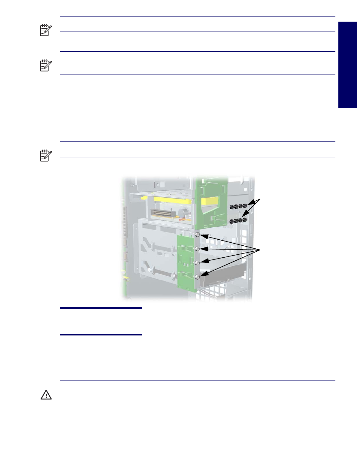
NOTE Metric screws have a black finish. American National (unified) screws have a silver finish.
NOTE As each subassembly is removed from the workstation, place the subassembly away from the
work area to prevent damage.
If necessary, additional drive guide screws are provided on the system chassis. There are eight Metric
screws located on the chassis near the 5.25-inch optical drive bays. These screws can be used to
mount additional optical drives or an optional diskette drive. There are four American National screws
located on the chassis near the hard drive. These screws can be used to mount additional hard drives in
the 3.5” hard drive cage. For more information about this procedure, see “Installing Hard Drives in the
5.5” slot (Optional)” on page 112.
NOTE The Metric (black) and American National (silver) screws are not interchangeable.
Chapter 4
1
2
1 Metric screws (8)
2 American National screws (4)
Special Handling of Components
The following components require special handling when servicing the workstation.
WARNING! Do not use the front bezel as a handle or lifting point when lifting or moving the workstation.
Lifting the workstation from the front bezel or lifting it incorrectly could cause the unit to fall and cause
harm to the user and damage to the workstation. To properly and safely lift the workstation, lift it from the
bottom of the unit from either the desktop or minitower configuration.
SERVICE CONSIDERATIONS 71

Cables and Connectors
Cables must be handled with care to avoid damage. Apply only the tension required to seat or unseat the
cables during insertion or removal from the connector. Handle cables by the connector whenever
possible. In all cases, avoid bending or twisting the cables, and ensure that the cables are routed in such
a way that they cannot be caught or snagged by parts being removed or replaced.
CAUTION When servicing this workstation, ensure that cables are placed in their proper location during
the reassembly process. Improper cable placement can damage the workstation.
Hard Drives
Handle hard drives as delicate, precision components, avoiding all physical shock and vibration. This
applies to failed drives as well as replacement spares.
If a drive must be mailed, place the drive in a bubble-pack mailer or other suitable protective
packaging and label the package “Fragile: Handle With Care.”
Do not remove hard drives from the shipping package for storage. Keep hard drives in their protective
packaging until they are actually mounted in the workstation.
Avoid dropping drives from any height onto any surface.
If you are inserting or removing a hard drive, turn off the workstation. Do not remove a hard drive
while the workstation is on or in standby mode.
Before handling a drive, ensure that you are discharged of static electricity. While handling a drive,
avoid touching the connector. For more information about preventing electrostatic damage, see
“Electrostatic Discharge Information” on page 68.
Do not use excessive force when inserting a drive.
Avoid exposing a hard drive to liquids, temperature extremes, or products that have magnetic fields,
such as monitors or speakers.
Lithium Coin Cell Battery
The battery that comes with the workstation provides power to the real-time clock and has a minimum
lifetime of about three years.
For instructions on battery removal and replacement procedures, see “Battery” on page 100.
WARNING! This workstation contains a lithium battery. There is a risk of fire and chemical burn if the
battery is handled improperly. Do not disassemble, crush, puncture, short external contacts, dispose in
water or fire, or expose it to temperatures higher than 140º F (60º C).
CAUTION Do not dispose of batteries, battery packs, and accumulators together with the general
household waste.
Batterij niet
weggooien,
maar inleveren
als KCA.
72 REMOVAL AND REPLACEMENT

Pre-Disassembly Procedures
Before servicing the workstation:
1 Remove/disengage any security devices that prohibit opening the workstation.
2 Close any open software applications.
3 Remove any diskette or compact disc from the workstation.
4 Exit the operating system.
5 Turn off the workstation and any peripheral devices that are connected to it.
6 Remove/disengage any security devices that prohibit opening the workstation.
CAUTION Turn off the workstation before disconnecting any cables.
CAUTION The cooling fan is off only when the workstation is turned off or the power cable has been
disconnected. The cooling fan is always on when the workstation is in the “On,” “Standby,” or “Suspend”
modes. You must disconnect the power cord from the power source before opening the workstation to
prevent system board or component damage.
7 Disconnect the power cord from the electrical outlet and then from the workstation.
8 Disconnect all peripheral device cables from the workstation. For more information, see “Electrostatic
Discharge Information” on page 68.
Chapter 4
Removal and Replacement of Components
This section discusses the procedures necessary to remove and install various hardware components
on your workstation. Review the safety and precautions and the “Service Considerations” on page 68, as
well as the
1 Read all safety information and precautions.
2 Locate and clear a suitable work area.
3 Shut down the system and remove power from the unit.
4 Gather your tools.
5 Service your unit.
6 Restore power to your unit.
Safety and Regulatory Guide,
before servicing or upgrading your system.
PRE-DISASSEMBLY PROCEDURES 73

Disassembly Order
Use the following table to determine the order in which to remove the major components.
Pre-Disassembly (page 73)
Locks (page 75)
Access (Hood) Panel (page 77)
Access Panel (Hood) Sensor (page 78)
Front Bezel (page 80)
Front Panel I/O Assembly (page 83)
Power Button (page 84)
System Speaker (page 87)
Optical Drive (page 102)
Diskette Drive (page 106)
Bezel Blanks (page 80)
Power Supply (page 85)
System Fan (page 86)
Memory (page 93)
Battery (page 100)
Hard Drive (page 107)
Processor Heatsink (page 88)
Processor (page 91)
System Speaker (page 87)
PCI or PCI Express Cards (page 98)
System Board (page 114)
74 REMOVAL AND REPLACEMENT

Security Padlock (Optional)
If a security padlock is installed, remove it before servicing the unit. To remove the padlock, unlock it and
slide it out of the padlock loop as shown in the following illustration.
Cable Lock (Optional)
Chapter 4
If a cable lock is installed, remove it before servicing the unit. To remove the cable lock, unlock it and pull
it out of the cable lock slot as shown in the following illustration.
REMOVAL AND REPLACEMENT OF COMPONENTS 75

Universal Chassis Clamp Lock (Optional)
If a universal chassis clamp lock is installed, remove it before servicing the unit. To remove the noble
lock:
1 Unlock the screw cover from the universal clamp as shown in the following illustration.
2 Unscrew the universal clamp from the unit as shown in the following illustration.
76 REMOVAL AND REPLACEMENT

Access Panel
Before accessing the internal components of the HP Workstation xw4200, the access panel must be
removed.
To remove the panel:
WARNING! Ensure that the workstation is turned off and that the power cord is disconnected from the
electrical outlet before removing the workstation access panel.
1 Disconnect power from the system (page 73) and, if necessary, unlock the security lock and cable
lock (page 75), and disconnect the universal clamp lock (page 76).
2 Lay the unit in the desktop position as shown in the following illustration.
3 Pull up and out on the cover latch 1 and at the same time slide the cover 2 away from the bezel and
then lift up.
2
1
Chapter 4
To replace the access panel, lay it flat on the unit about one inch from the bezel. The hooks should fall
into the recesses. Then slide the cover towards the bezel until it snaps into place.
REMOVAL AND REPLACEMENT OF COMPONENTS 77

Access Panel (Hood) Sensor (Optional)
To remove the hood sensor:
1 Disconnect power from the system (page 73) and remove the access panel (page 77).
2 Disconnect the hood sensor 1 from the system board.
3 Slide the hood sensor 2 forward as shown in the following illustration.
CAUTION The hood sensor bracket and the chassis contain sharp edges that present a safety hazard.
Be careful when sliding the hood sensor forward.
4 Pull the hood sensor 3 down and remove it from the chassis.
2
3
To replace the hood sensor, reverse the previous steps.
1
78 REMOVAL AND REPLACEMENT

Solenoid Hood (Smart Cover) Lock (Optional)
To remove the solenoid lock:
1 Disconnect power from the system (page 73) and remove the access panel (page 77).
2 Disconnect the access panel lock cable 1 from the system board.
3 Using the FailSafe key, unscrew the two screws 2 from the back of the chassis as shown in the
following diagram.
4 Slide the access panel lock assembly 3 away from the chassis and out of the unit.
2
3
1
To replace the access panel lock assembly, reverse the previous steps.
Chapter 4
REMOVAL AND REPLACEMENT OF COMPONENTS 79

Front Bezel
To remove the bezel:
1 Disconnect power from the system (page 73) and remove the access panel (page 77).
2 Lift up on the two tabs 1 located on the front bezel.
3 Rotate the front bezel 2 away from the chassis as shown in the following illustration and remove the
bezel.
1
2
Bezel Blanks
To remove the bezel blanks:
1 Disconnect power from the system (page 73), and remove the access panel (page 80) and front
bezel. After removing the front bezel, gently pull the subpanel 1, with the bezel blanks secured in it,
away from the front bezel.
2 Remove the desired bezel blank 2 by pulling the blank away from the subpanel.
1
NOTE The bezel blanks are keyed to assist you in replacing the blanks. Also, the subpanel can be
rotated 90 degrees to install the optical drives in desktop orientation, if desired.
2
80 REMOVAL AND REPLACEMENT

Chassis Feet
The HP Workstation xw4200 ships in a minitower configuration and chassis feet are installed on the base
of the workstation. The unit ships with additional feet should you convert the unit to a desktop.
To install the chassis feet on a desktop-oriented workstation:
1 Situate the unit into the appropriate position as shown in the following illustration.
2 Place the feet into the embossed areas of the unit.
Chapter 4
REMOVAL AND REPLACEMENT OF COMPONENTS 81
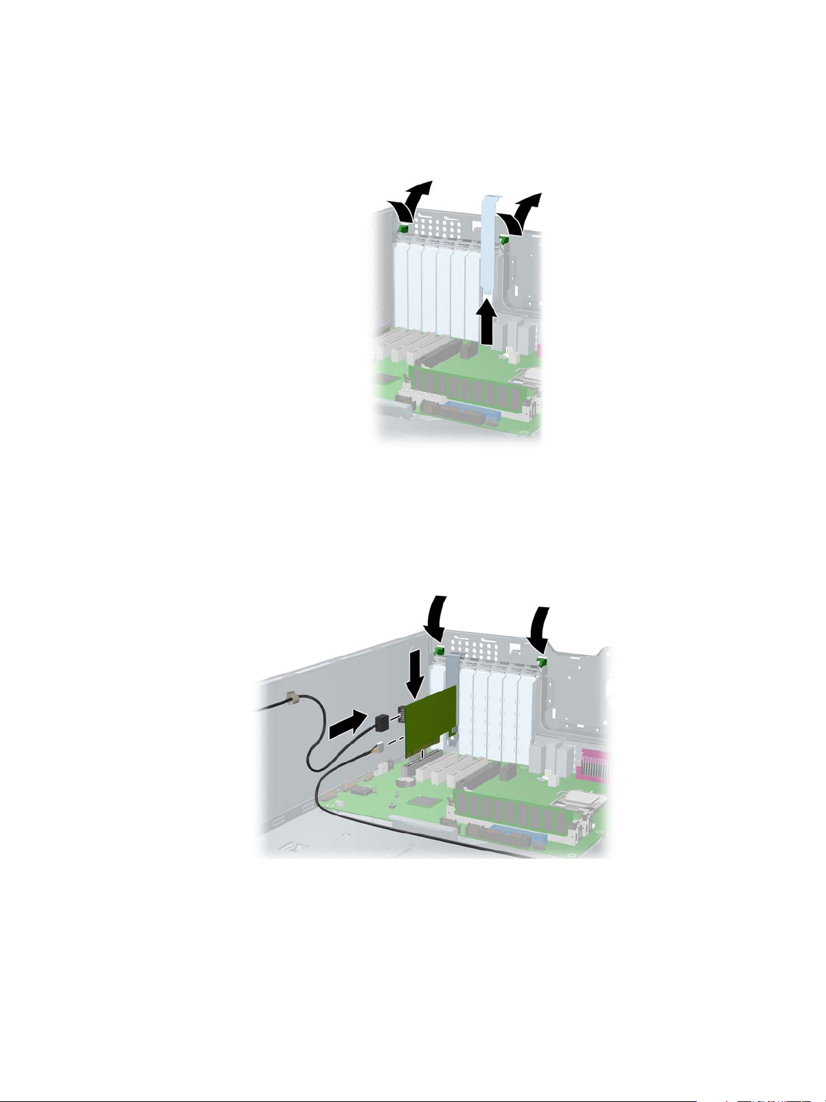
IEEE-1394 (Optional)
To install an optional IEEE-1394 adapter:
1 Unlatch the PCI levers 1 and the PCI slot cover 2.
1
2
2 Install the IEEE-1394 card 3 into the PCI socket.
3 Close the PCI levers 4.
4 Connect the front I/O cable 5 and power cable 6 into the card.
5 Remove the sticker covering the front IEEE-1394 connector.
1
4
3
5
6
4
82 REMOVAL AND REPLACEMENT

Front Panel I/O Assembly
To remove the front panel I/O assembly:
1 Disconnect power from the system (page 73), remove the access panel (page 77), and remove the
front bezel (page 80).
2 Disconnect the front panel I/O assembly cable from the system board.
3 Remove the two screws 1 that hold the assembly bracket to the chassis as shown in the following
illustration.
4 Remove the two screws 2 that hold the bracket and assembly together and separate the shield away
from the front panel I/O assembly 3.
5 Slide the front panel I/O assembly 4 (with bracket attached) out about two inches away from the
chassis.
4
Chapter 4
2
1
1
WARNING! The next step requires the removal of cables through the chassis. Some edges on the
chassis might be sharp. Care must be taken when removing these cables.
6 Slide the front panel cables through the chassis and out the front of the unit.
To replace the front panel I/O assembly, reverse the previous steps.
2
3
REMOVAL AND REPLACEMENT OF COMPONENTS 83

Power Button Assembly
To remove the front power button assembly:
1 Disconnect power from the system (page 73), remove the access panel (page 77), remove the front
bezel (page 80), and remove the front panel I/O assembly (page 83).
2 Disconnect the power assembly cable from the system board.
3 Press the clips at the top 1 and bottom 2 of the power assembly, then slide the assembly out from the
front of the chassis as shown in the following illustration.
1
2
84 REMOVAL AND REPLACEMENT

Power Supply
To remove the power supply:
1 Disconnect power from the system (page 73) and remove the access panel (page 77).
2 Disconnect the power supply from the system board.
3 Disconnect all devices (optical drives, diskette drive, hard drives, and on select models, the graphics
card and IEEE-1394 card) from the power supply.
4 Remove the four screws 1 from the back panel.
1
2
5 Slide the power supply 2 toward the front and lift up to remove it from the chassis.
Chapter 4
To install the power supply, reverse the previous steps.
REMOVAL AND REPLACEMENT OF COMPONENTS 85

System Fan
To remove the system fan:
1 Disconnect power from the system (page 73) and remove the access panel (page 77).
2 Disconnect the fan connector 1 from the system board.
3 Remove the four screws 2 from the back of the chassis back panel with a Phillips screwdriver.
2
3
1
4 Slide the fan 3 toward the front of the unit and remove it.
To replace a system fan, reverse the previous steps.
CAUTION When installing the system fan, ensure that the fan is situated so that the airflow direction is
going out of the chassis.
NOTE This system only supports 4-wire fans.
86 REMOVAL AND REPLACEMENT
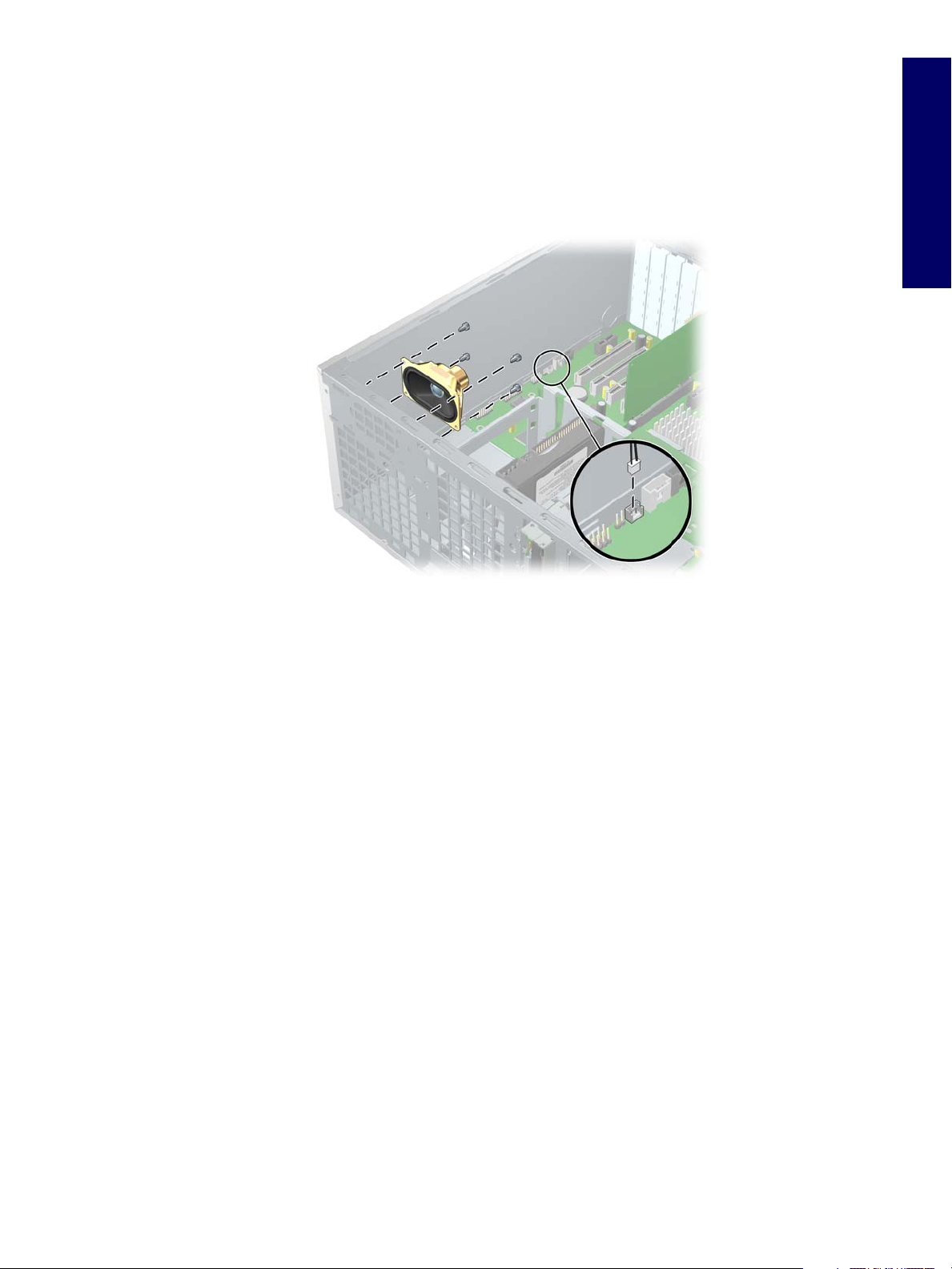
System Speaker
To remove the speaker:
1 Disconnect power from the system (page 73) and remove the access panel (page 77).
2 Disconnect the speaker 1 from the system board.
3 Remove the four screws 2 as shown in the following illustration.
2
1
4 Pull the speaker out of the chassis.
To replace the speaker, reverse the previous steps.
Chapter 4
REMOVAL AND REPLACEMENT OF COMPONENTS 87
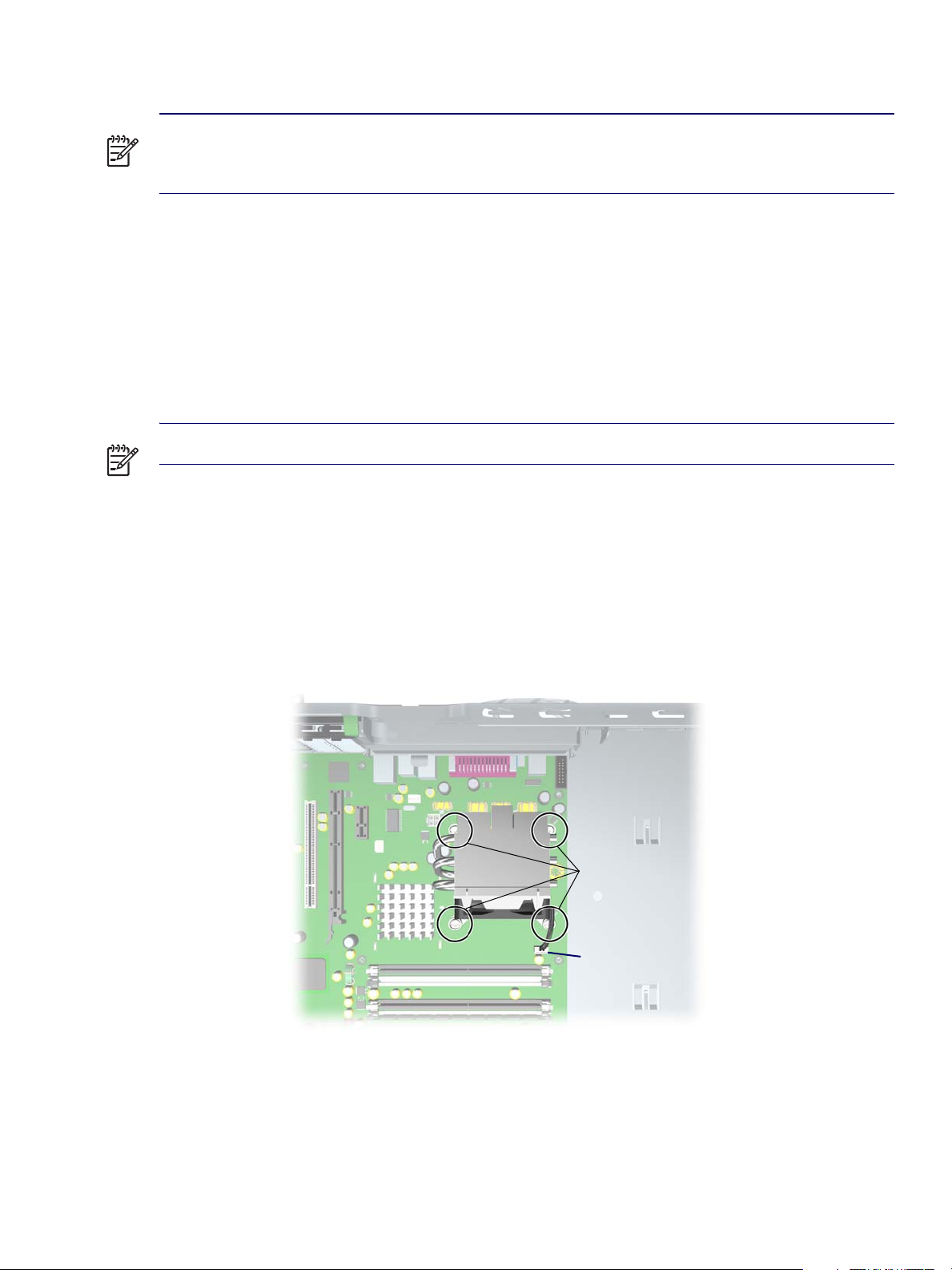
Processor Heatsink
NOTE The following illustrated heatsink is typical of what you might have in your workstation. Be aware
that different versions of the heatsinks exist, but the overall procedures listed are sufficient to assist you
in removing the heatsink.
Removing the Heatsink
To remove the heatsink:
1 Turn on the workstation and enter Computer Setup (F10) (page 34). Let the workstation run in this
mode for five minutes.
This action warms the thermal interface material between the heatsink and processor so that the
thermal bond loosens, and can more easily be broken.
NOTE Windows in idle state does not provide sufficient heat to warm the compound.
2 After warming the thermal interface, shut down the system, disconnect power from the system
(page 73), and remove the access panel (page 77).
3 Disconnect the heatsink wire 1 from the system board as shown in the two illustrations below.
4 Remove the captured heatsink screws 2 from the system board. Begin by slightly loosening any two
screws that diagonally opposite from one another, then slightly loosen the other two. Then finish
removing the screws.
5 Gently twist the heatsink unit to break the thermal grease binding.
2
1
88 REMOVAL AND REPLACEMENT

6 Lift the heatsink 3 unit. Use alcohol and a soft cloth to clean all the thermal interface material residue
from the processor heatsink and processor.
CAUTION Allow the alcohol on the processor heatsink to dry completely.
3
1
Chapter 4
REMOVAL AND REPLACEMENT OF COMPONENTS 89

Replacing the Heatsink
To replace the heatsink:
1 Disconnect power from the system (page 73), remove the access panel (page 77), and remove the
heatsink (page 88).
2 Use alcohol and a soft cloth to clean all the thermal interface material residue from the processor
heatsink and processor.
CAUTION Allow the alcohol on the processor heatsink to dry completely.
Apply new thermal grease between the heatsink and processor, then reverse the previous steps. Do not
fully tighten one screw, then move on to the next. Tighten all screws a little at a time, making sure the
processor remains level.
NOTE This system only supports 4-wire fans.
90 REMOVAL AND REPLACEMENT

Processor
To remove the processor:
1 Disconnect power from the system (page 73), remove the access panel (page 77), and remove the
heatsink (page 88).
2 Raise the lever 1 on the processor socket handle and open the cover 2.
2
1
Chapter 4
3 Pull the processor 3 straight out of the socket.
CAUTION If you damage the spring-loaded contacts in the socket, the system board may be damaged
and your warranty voided.
3
REMOVAL AND REPLACEMENT OF COMPONENTS 91

NOTE Store the processor in a safe place where it will not be damaged.
To replace the processor:
1 Raise the processor socket handle fully (the full swing angle of the lever is approximately 135
degrees).
CAUTION The contacts in the socket are delicate. Use extreme care when placing the processor in the
socket.
2 Line up the triangle on the corner of the processor with the triangle on the corner of the processor
socket and install the processor into the socket. Ensure that the underside of the processor is level
with the top of the top of the processor socket. Lightly press down on the top of the processor while
closing the socket lever.
92 REMOVAL AND REPLACEMENT

Memory
The HP Workstation xw4200 has four memory sockets. The system supports industry-standard, 240-pin
DDR2 DIMMs.
The system can support up to 4 GB of memory (1-GB DIMM in each socket). Although a single 128-MB
DIMM configuration is possible (on XMM1 only), always install DIMMs in pairs for optimal dual-channel
operation.
Memory Module Requirements
Use only industry standard, unbuffered, PC2-3200 or PC2-4300 DIMMs.
Install unbuffered DDR2 DIMMs in pairs of matched size and type.
Registered memory is not supported.
Removing Memory Module
To remove DIMMs from the unit:
1 Disconnect power from the system (page 73), remove the access panel (page 77), and lay the
workstation on its side with the system board facing up.
CAUTION To ensure that memory modules are not damaged during removal or installation, power off
the workstation and unplug the power cord from the AC power outlet. Wait until the LED on the back of
the power supply turns off before removing memory. If you do not unplug the power cord while installing
memory, your memory modules might be damaged and the system will not recognize the memory
changes.
Chapter 4
2 Gently push outwards on the socket levers 1 as shown in the following illustration.
3 Lift the DIMM 2 straight up and remove it from the unit.
2
1
1
To replace memory, reverse the previous steps.
REMOVAL AND REPLACEMENT OF COMPONENTS 93

NOTE DIMMs and the DIMM sockets are keyed for proper installation. Make sure the guides line up
when installing a DIMM.
Installing Memory Module
You must load memory modules in valid configurations.
If using only one DIMM, install it in socket 1
Load the first DIMM pair A into sockets 1 and 3.
Load the second DIMM pair B into sockets 2 and 4.
12
AB
34
94 REMOVAL AND REPLACEMENT

Peripheral Component Interconnect (PCI) Slots
1
2
3
4
5
6
7
Tabl e 4 -3 PCI Slots
Slot Type Ref IDSEL INTs PME
Chapter 4
1 PCI Express x1 J34 N/A A B C D PCI_EXP_WAKE#
2 PCI Express x16 J41 N/A A B C D PCI_EXP_WAKE#
3 PCI J20 AD20 A C F G P_PME#
4 PCI J21 AD25 C F G A P_PME#
5 PCI J22 AD26 F G A C P_PME#
6 PCI J23 AD27 G A C F P_PME#
7 PCI Express x1 J31 N/A A B C D PCI_EXP_WAKE#
Tabl e 4 -4 PCI Devices List
Device Bus Dev FN PFA Interrupts
Processor to I/O
Controller
MCH PCI Express
Root Port (slot 2)
ICH6R PCI Express
Root Port (Slot 1)
0000000
0100008A
0 28 0 00E0 A
ICH6R PCI Express
Root Port (Slot 7)
ICH6R PCI Express
Root Port (LAN)
0 28 1 00E1 B
0 28 3 00E3 D
REMOVAL AND REPLACEMENT OF COMPONENTS 95

Tabl e 4 -4 PCI Devices List
Device Bus Dev FN PFA Interrupts
ICH6R USB
Universal Host
Controller
ICH6R USB
Universal Host
Controller
ICH6R USB
Universal Host
Controller
ICH6R USB
Universal Host
Controller
ICH6R USB2
Enhanced Host
Controller
ICH6R PCI Bridge 0 30 0 00F0
ICH6R AC '97 0 30 2 00F2 A
ICH6R LPC
Interface Controller
ICH6R Ultra ATA
Storage Controllers
0 29 0 00E8 A
0 29 1 00E9 B
0 29 2 00EA C
0 29 3 00EB D
0 29 7 00EF A
0 31 0 00F8
0 31 1 00F9 A
ICH6R SATA
Controller
Slot 2 (PCI Express
x16)
Slot 3 (PCI) 5 4 0 0520 ACFG
Slot 4 (PCI) 5 9 0 0548 CFGA
Slot 5 (PCI) 5 10 0 0550 FGAC
Slot 6 (PCI) 5 11 0 0558 GACF
Slot 1 (PCI express
x1)
Slot 7 (PCI Express
x1)
Gigabit LAN
Controller
0 31 2 00FA B
1000100ABCD
32 0 0 2000 ABCD
64 0 0 4000 ABCD
128 0 0 8000 A
96 REMOVAL AND REPLACEMENT

PCI Express
PCI Express is a new hardware interconnect standard (for example, I/O slots). PCI Express is point-topoint architecture and uses a serial data transmission protocol. A single PCI Express lane consists of 4
wires and is capable of transmitting 250 MB/sec in a single direction or 500 MB/sec in both directions
simultaneously. This bandwidth is not affected by what is happening on other PCI Express buses or
legacy PCI/PCI-X buses (provided that total bandwidth can be handled by the CPU and the memory
subsystem). The transmission protocol is somewhat similar to that used for a LAN connection and
contains error correction and detection, packet addressing and other network features.
PCI Express improves system attributes. PCI Express enables a low-power, scalable, high-bandwidth
communication path with a small number of connections (wires) compared to traditional parallel
interfaces (for example, PCI).
The PCI Express I/O slots can support other PCI Express cards with lesser bus bandwidth than what is
physically defined for the slot. Use the following table to determine compatibility.
For example, a PCI Express x4 card does not work in a PCI Express x16 slot, but a PCI Express x16
card works in a PCI Express x16 slot.
Chapter 4
Tabl e 4 -5
PCI Express x1 Card Y not available not available Y
PCI Express x4 Card N not available not available N
PCI Express x8 Card N not available not available N
PCI Express x16 Card N not available not available Y
PCI Express Compatibility Matrix for xw4200
PCI Express x1 Slot PCI Express x4 Slot PCI Express x8 Slot PCI Express x16 Slot
REMOVAL AND REPLACEMENT OF COMPONENTS 97

PCI or PCI Express Removal
To remove a PCI or PCI Express card:
1 Disconnect power from the system (page 73), remove the access panel (page 77), lay the
workstation on its side with the system board facing up, and remove the PCI retainer (page 97).
2 Lift the PCI levers 1 by first pressing down on them and then out.
3 Lift the PCI card (2, left) out of the chassis. If removing a PCI Express card (2, right), remove the
power supply cable (not shown), if required, and move the “hockey stick” lever 3 to release the card
and lift it out of the chassis. Store the card in an anti-static bag.
4 Close the PCI levers.
Figure 4-1
1
1
3
2
PCI card removal (left) and PCI Express card removal (right)
1
1
2
98 REMOVAL AND REPLACEMENT

PCI or PCI Express Installation
To install a PCI or PCI Express card:
1 Disconnect power from the system (page 73), remove the access panel (page 77), lay the
workstation on its side with the system board facing up, and remove the PCI retainer (page 97).
2 Lift the PCI levers 1 by first pressing down on them and then out.
3 Remove the PCI slot cover 2.
4 Install the PCI card (3, left) or PCI Express card (3, right) into the chassis. Verify that the keyed
components of the card align with the PCI socket. If installing a PCI Express card, plug in the power
supply cable, if required.
5 Close the PCI levers 4. If the PCI levers do not close, be sure all cards are properly seated and then
try again.
6 If installing a PCI Express card, plug in the power supply cable 5, if required.
1
2
4
1
3
4
2
1
1
4
3
5
4
Chapter 4
Figure 4-2
PCI card installation (left) and PCI Express Card Installation (right)
REMOVAL AND REPLACEMENT OF COMPONENTS 99

Battery
CAUTION Back up your CMOS (complementary metal oxide semiconductor) settings before removing
the battery, as all CMOS settings will be lost when the battery is removed. To back up the CMOS
settings, in (F10 Setup click File>Replicated Setup>Save to Removable Media.
To remove the battery:
1 Disconnect power from the system (page 73), remove the access panel (page 77), and lay the
workstation on its side with the system board facing up.
2 Press on the release tab 1 of the battery holder as shown in the following illustration.
3 Slide and lift the battery 2 out.
2
1
To install the battery, slide the battery back in until it snaps back into place.
100 REMOVAL AND REPLACEMENT
 Loading...