

Page 1

Setup and Troubleshooting
HP xw4200, xw6200, xw8200, and xw9300
Workstations
Part number: 361756-002
First edition: 02/2005
Page 2

Legal and notice information
© Copyright 2004-2005 Hewlett-Packard Development Company, L.P.
The information contained herein is subject to change without notice.
Microsoft and Windows are U.S. registered trademarks of Microsoft Corporation.
Linux is a registered trademark of Linus Tolvalds.
Intel is a trademark of Intel Corporation in the U.S. and other countries.
Adobe, Acrobat, and Acrobat Reader are trademarks or registered trademarks of Adobe Systems Incorporated.
Energy Star is a US registered mark of the United States Environmental Protection Agency.
The only warranties for HP products and services are set forth in the express warranty statements accompanying such products and services.
Nothing herein should be construed as constituting an additional warranty. HP shall not be liable for technical or editorial errors or omissions
contained herein.
This document contains proprietary information that is protected by copyright. No part of this document may be photocopied, reproduced, or
translated to another language without the prior written consent of Hewlett-Packard Company.
Page 3

Page 4

Page 5

Contents
1 Locating HP Resources
Using the Documentation and Diagnostics CD . . . . . . . . . . . . . . . . . . . . . . . . . . . . . . . . . . . . . . . . . . . . 8
2 Hardware Setup
Quick Setup. . . . . . . . . . . . . . . . . . . . . . . . . . . . . . . . . . . . . . . . . . . . . . . . . . . . . . . . . . . . . . . . . . . 11
Front Panel Components . . . . . . . . . . . . . . . . . . . . . . . . . . . . . . . . . . . . . . . . . . . . . . . . . . . . . . . . . . 13
Rear Panel Components. . . . . . . . . . . . . . . . . . . . . . . . . . . . . . . . . . . . . . . . . . . . . . . . . . . . . . . . . . . 16
Keyboard . . . . . . . . . . . . . . . . . . . . . . . . . . . . . . . . . . . . . . . . . . . . . . . . . . . . . . . . . . . . . . . . . . . . 20
Special Mouse Functions . . . . . . . . . . . . . . . . . . . . . . . . . . . . . . . . . . . . . . . . . . . . . . . . . . . . . . . . . . 21
Serial Number and COA Label Location . . . . . . . . . . . . . . . . . . . . . . . . . . . . . . . . . . . . . . . . . . . . . . . 22
3 Software Setup
Installing and Customizing Windows XP Workstations . . . . . . . . . . . . . . . . . . . . . . . . . . . . . . . . . . . . . 23
Starting up the Operating System . . . . . . . . . . . . . . . . . . . . . . . . . . . . . . . . . . . . . . . . . . . . . . . . . 23
Restoring the Software . . . . . . . . . . . . . . . . . . . . . . . . . . . . . . . . . . . . . . . . . . . . . . . . . . . . . . . . . 24
Installing or Upgrading Device Drivers . . . . . . . . . . . . . . . . . . . . . . . . . . . . . . . . . . . . . . . . . . . . . . 24
Energy Star. . . . . . . . . . . . . . . . . . . . . . . . . . . . . . . . . . . . . . . . . . . . . . . . . . . . . . . . . . . . . . . . . 24
Accessibility . . . . . . . . . . . . . . . . . . . . . . . . . . . . . . . . . . . . . . . . . . . . . . . . . . . . . . . . . . . . . . . . 25
Customizing the Monitor Display . . . . . . . . . . . . . . . . . . . . . . . . . . . . . . . . . . . . . . . . . . . . . . . . . . 25
Installing and Customizing
Linux–preinstalled Workstations . . . . . . . . . . . . . . . . . . . . . . . . . . . . . . . . . . . . . . . . . . . . . . . . . . . . . 25
Starting up the Linux Operating System . . . . . . . . . . . . . . . . . . . . . . . . . . . . . . . . . . . . . . . . . . . . . 26
Restoring the Linux Operating System. . . . . . . . . . . . . . . . . . . . . . . . . . . . . . . . . . . . . . . . . . . . . . . 26
Upgrading Device Drivers. . . . . . . . . . . . . . . . . . . . . . . . . . . . . . . . . . . . . . . . . . . . . . . . . . . . . . . 27
Installing and Customizing Linux–enabled Workstations . . . . . . . . . . . . . . . . . . . . . . . . . . . . . . . . . . . . 27
Verifying Hardware Compatibility . . . . . . . . . . . . . . . . . . . . . . . . . . . . . . . . . . . . . . . . . . . . . . . . . 27
Installing the Linux Operating System . . . . . . . . . . . . . . . . . . . . . . . . . . . . . . . . . . . . . . . . . . . . . . . 27
Upgrading Device Drivers. . . . . . . . . . . . . . . . . . . . . . . . . . . . . . . . . . . . . . . . . . . . . . . . . . . . . . . 28
After First-Boot . . . . . . . . . . . . . . . . . . . . . . . . . . . . . . . . . . . . . . . . . . . . . . . . . . . . . . . . . . . . . . . . . 28
Hyper-Threading Technology . . . . . . . . . . . . . . . . . . . . . . . . . . . . . . . . . . . . . . . . . . . . . . . . . . . . . . . 28
Turning off the Workstation . . . . . . . . . . . . . . . . . . . . . . . . . . . . . . . . . . . . . . . . . . . . . . . . . . . . . . . . 29
Upgrading the BIOS . . . . . . . . . . . . . . . . . . . . . . . . . . . . . . . . . . . . . . . . . . . . . . . . . . . . . . . . . . . . . 29
Subscribing to Software Support. . . . . . . . . . . . . . . . . . . . . . . . . . . . . . . . . . . . . . . . . . . . . . . . . . . . . 30
HP ProtectTools Embedded Security . . . . . . . . . . . . . . . . . . . . . . . . . . . . . . . . . . . . . . . . . . . . . . . . . . 30
Contents
4 Troubleshooting
Self Troubleshooting . . . . . . . . . . . . . . . . . . . . . . . . . . . . . . . . . . . . . . . . . . . . . . . . . . . . . . . . . . . . . 31
HP Troubleshooting Resources and Tools . . . . . . . . . . . . . . . . . . . . . . . . . . . . . . . . . . . . . . . . . . . . . . . 31
POST Error Messages . . . . . . . . . . . . . . . . . . . . . . . . . . . . . . . . . . . . . . . . . . . . . . . . . . . . . . . . . . . . 34
Basic Troubleshooting . . . . . . . . . . . . . . . . . . . . . . . . . . . . . . . . . . . . . . . . . . . . . . . . . . . . . . . . . . . . 34
Calling Technical Support . . . . . . . . . . . . . . . . . . . . . . . . . . . . . . . . . . . . . . . . . . . . . . . . . . . . . . . . . 41
A Features and Accessories
Security Features . . . . . . . . . . . . . . . . . . . . . . . . . . . . . . . . . . . . . . . . . . . . . . . . . . . . . . . . . . . . . . . 43
Chassis Conversion Features . . . . . . . . . . . . . . . . . . . . . . . . . . . . . . . . . . . . . . . . . . . . . . . . . . . . . . . 43
Accessories . . . . . . . . . . . . . . . . . . . . . . . . . . . . . . . . . . . . . . . . . . . . . . . . . . . . . . . . . . . . . . . . . . . 44
Index . . . . . . . . . . . . . . . . . . . . . . . . . . . . . . . . . . . . . . . . . . . . . . . . . . . 45
Contents
5
Page 6

6Contents
Page 7

1 Locating HP Resources
Table 1-1 Locating HP Resources
What Do You Need Help With? Where to Find It?
Locating additional information. For online access to technical support information and
tools, visit www.hp.com/support
include web-based troubleshooting tools, technical
knowledge databases, driver and patch downloads,
online communities, and proactive notification services.
. Support resources
Locating HP user documentation, white papers, and thirdparty documentation.
Finding regulatory information. Refer to the Safety & Regulatory Information Guide on the
Locating parts and accessories. For complete and current information on supported
Exploring the contents on the Documentation and
Diagnostics CD.
Signing up for product notifications. Subscriber's Choice is an HP program that allows you to
For the latest online documentation, visit www.hp.com/
support/workstation_manuals.
Documentation and Diagnostics CD for product Class
information. You can also refer to the label on the
workstation chassis.
accessories and components, visit
http://partsurfer.hp.com
For information on using the CD as a documentation tool
or a diagnostics tool, see “Using the Documentation and
Diagnostics CD” on page 8 of this chapter.
The Documentation and Diagnostics CD includes:
• a copy of the Setup and Troubleshooting Guide
• a link to the latest Service and Technical Reference
Guide
• a copy of the Safety and Comfort Guide
• a copy of the Safety & Regulatory Information Guide
• HP Insight Diagnostics utility
sign up to receive driver and software alerts, proactive
change notifications (PCNs), the HP newsletter, and
more. Sign up today at www.hp.com/go/
subscriberschoice.
.
Locating HP Resources
Locating workstation QuickSpecs. The Product Bulletin contains QuickSpecs for HP
workstations. QuickSpecs provide an overall specification
review of your product. It includes information about its
features including the operating system, power supply,
memory, processor, and many other components of the
system. To access the QuickSpecs, visit http://
h18000.www1.hp.com
/products/quickspecs
/productbulletin.html.
Locating warranty information. Each system comes with a printed copy of the warranty
statement.
7
Page 8

Table 1-1 Locating HP Resources
What Do You Need Help With? Where to Find It?
Locating information about the system board. The inside of the access panel contains an illustration of
the system board layout. Also, you can find additional
information by reviewing the Service and Technical
Reference Guide that can be found on the Documentation
and Diagnostics CD or on the Web.
Locating diagnostics tools. The Documentation and Diagnostics CD contains the HP
Insight Diagnostics utility.To use this utility, see “HP Insight
Diagnostics” on page 23.
Locating the latest drivers. Verify you have the latest drivers for your system by
visiting http://welcome.hp.com/country/us/en/
support.html.
Determining the meaning of beep and LED codes. See “Diagnostic Lights and Audible (Beep) Codes” on
page 30 for detailed information about beep and LED
codes applicable to the workstation.
Locating the serial number and COA label (if applicable). The serial number labels can be found on the top panel
or on the side of the unit and at the rear of the unit. The
COA label is generally located on the top panel or
access panel near the serial number label.
Reinstalling the operating system. See “Software Setup” on page 23 for more information
on how to load the operating system.
Finding information on how to contact technical support.
Before you call technical support, see “Self
Troubleshooting” on page 23 for self-troubleshooting
information. To facilitate your call, see “Calling Technical
Support” on page 33for a listing of information you need
to have available before you call.
For U.S. and Canada, call 1-800-HPINVENT. For a listing
of all worldwide technical support phone numbers, visit
http://welcome.hp.com/country/us/eng/
wwcontact.html.
Using the Documentation and Diagnostics CD
Accessing Documentation
To access the documentation contents of the Documentation and Diagnostics CD, follow the steps below
that are applicable to your workstation.
Windows-based Workstations
Insert the CD into the CD-ROM drive. The CD will Autorun. If there is no CD-ROM drive activity for two
minutes or more, the Autorun feature may not be enabled on the workstation. To run the CD, follow these
steps:
1. Click Start > Run.
Locating HP Resources8
Page 9

2. Type:
X:\index.htm (where X is the drive letter designator for the CD-ROM drive)
3. Click OK.
Linux-based Workstations
If the workstation is running a Linux operating system, browse the CD and click on the index.htm file to
launch the CD interface. To view the documents on the CD, download and install Adobe® Acrobat®
Reader for Linux from www.adobe.com
Accessing Diagnostics
To use the HP Insight Diagnostics utility, insert the Documentation and Diagnostics CD into your system and
reboot. Follow the onscreen menu options and directions to begin your testing.
NOTE: Should you not have the Documentation and Diagnostics CD available, you can download the
image from www.hp.com/go/workstationsupport
1. Click on your workstation model link then click the download drivers and software link.
2. Select your language and then click the appropriate operating system link.
3. From the download drivers and software screen, click the Diagnostics link and then click the
appropriate diagnostic program link.
.
.
Locating HP Resources
Using the Documentation and Diagnostics CD
9
Page 10

Locating HP Resources10
Page 11

2Hardware Setup
Quick Setup
After unpacking your workstation, locate an accessible workspace to set up the workstation and connect
the mouse, keyboard, monitor(s), and power cables to your workstation. Connect the power cables from
the monitor and workstation to a power outlet.
Figure 2-1 Cable Connections
NOTE: Connect other components, such as a printer, according to the instructions included with the
device.For more information on your workstation, refer to the Documentation and Diagnostics CD or visit
www.hp.com/go/workstationsupport.
Hardware Setup
Quick Setup 11
Page 12

Ventilation
Proper ventilation for your system is very important. Refer to the following notes and illustrations to properly
position your system for maximum airflow
• Place the computer in an area that is relatively cool with adequate ventilation.
• Operate the computer on a sturdy, level surface. Leave a 10.2-cm (4-inch) clearance on all vented
sides of the computer and above the monitor to permit the required airflow.
• Never restrict the airflow into the computer by blocking any vents or air intakes. Do not place the
keyboard, with the keyboard feet down, directly against the front of the desktop unit as this also
restricts airflow.
Figure 2-2 Ventilation Guidelines
Hardware Setup12
Page 13

Front Panel Components
xw4200 Front Panel Components
1
2
3
7
8
4
5
6
9
10
11
12
13
14
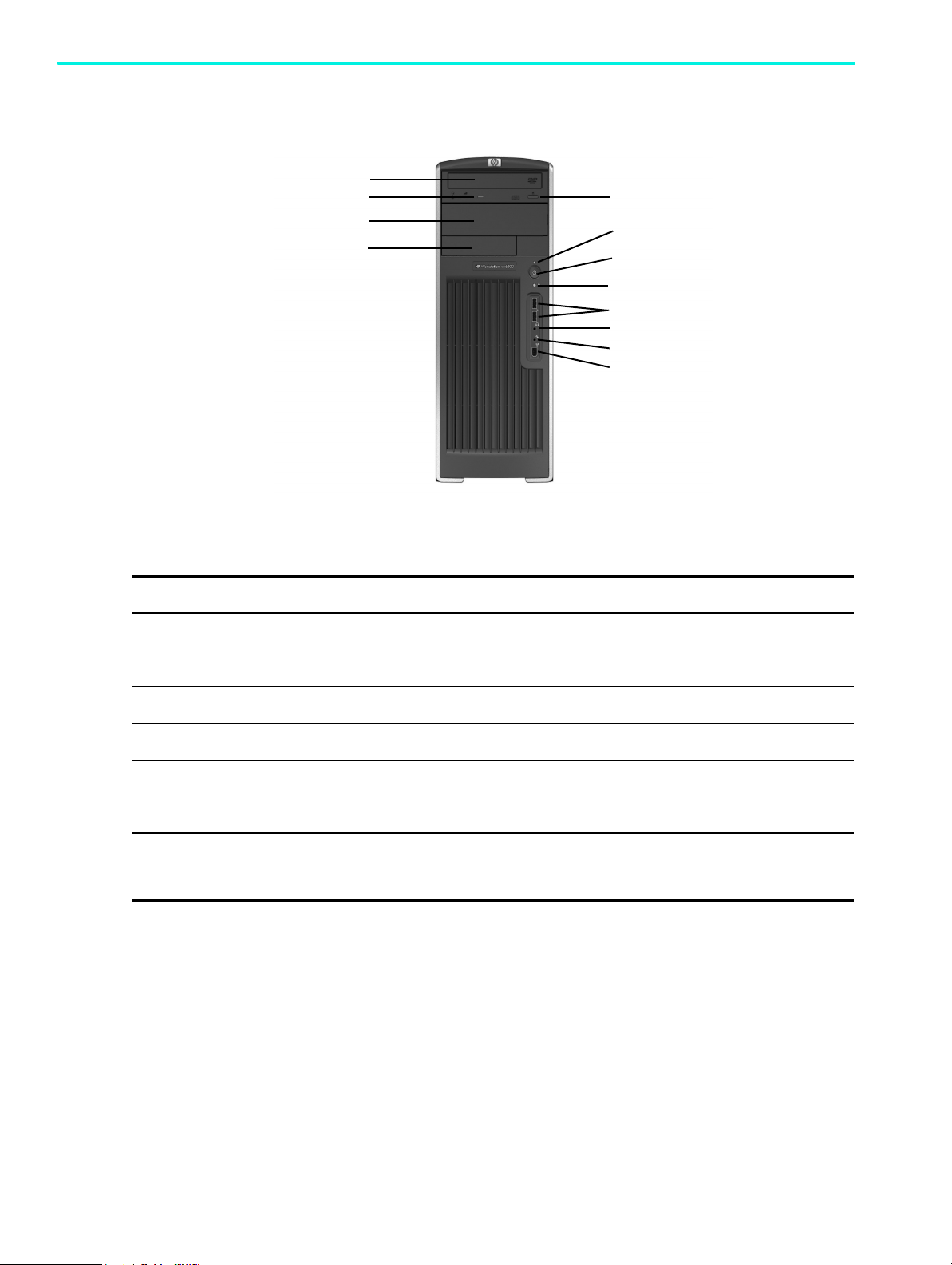
Figure 2-3 xw4200 Front Panel Components
Table 2-2 xw4200 Front Panel Components
Item Description Item Description
1 Optical Drive* 8 Power On Light
2 Optical Drive Activity Lights 9 Power But ton
3 5.25 Inch Drive Bays 10 Hard Drive Activity Light
4 Diskette Drive (optional) 11 USB (Universal Serial Bus) Ports
Hardware Setup
5 Diskette Drive Activity Light 12 Headphone Connector
6 Diskette Eject Button 13 Microphone Connector
7 Optical Drive Eject Button 14 IEEE-1394a Connector**
NOTE: * An optical drive is a CD-ROM, CD-R/RW, DVD-ROM, DVD+R/RW, or CD-RW/DVD combo drive.
NOTE: ** IEEE-1394a is an optional feature. If the unit was purchased without this option, then this connector will be covered with
a black label.
Front Panel Components 13
Page 14
xw6200 Front Panel Components
1
2
3
4
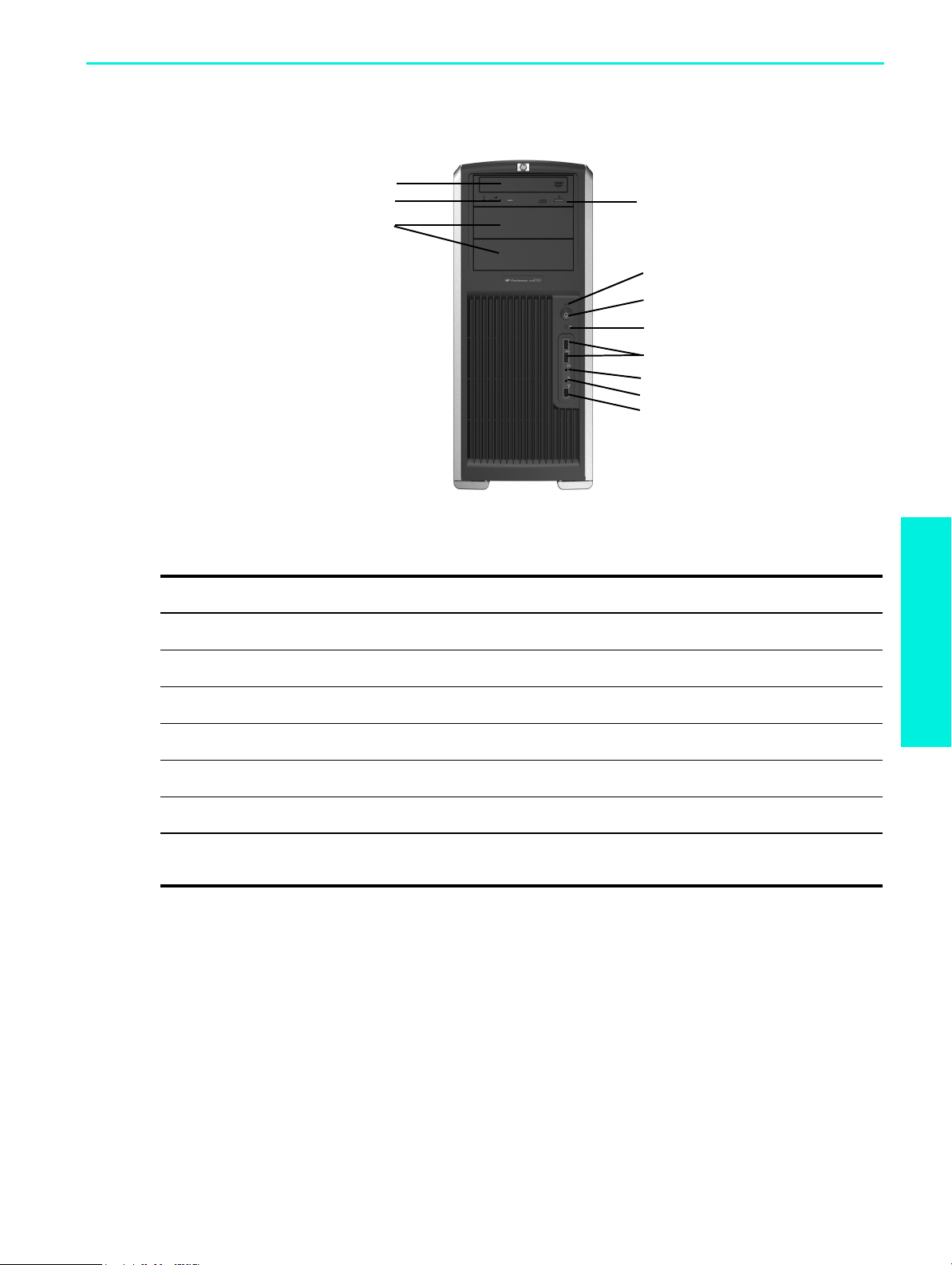
Figure 2-4 xw6200 Front Panel Components
Table 2-3 xw6200 Front Panel Components
5
6
7
8
9
10
11
12
Item Description Item Description
1 Optical Drive* 7 Power But ton
2 Optical Drive Activity Lights 8 Hard Drive Activity Light
3 5.25 Inch Drive Bays 9 USB Ports (2)
4 Diskette Drive (optional) 10 Headphone Connector
5 Optical Drive Eject Button 11 Microphone Connector
6 Power On Light 12 IEEE-1394a Connector**
NOTE: * An optical drive is a CD-ROM, CD-R/RW, DVD-ROM, DVD+R/RW, or CD-RW/DVD combo drive.
NOTE: ** IEEE-1394a is an optional feature. If the unit was purchased without this option, then this connector will be covered with
a black label.
Hardware Setup14
Page 15
xw8200 and xw9300 Front Panel Components
1
2
3
Figure 2-5 xw8200 and xw9300 Front Panel Components
Table 2-4 xw8200 and xw9300 Front Panel Components
4
5
6
7
8
9
10
11
Item Description Item Description
1 Optical Drive* 7 Hard Drive Activity Light
2 Optical Drive Activity Lights 8 USB Ports (2)
3 5.25 Inch Drive Bays** 9 Headphone Connector
4 Optical Drive Eject Button 10 Microphone Connector
5 Power On Light 11 IEEE-1394a Connector
6 Power Button
NOTE: * An optical drive is a CD-ROM, CD-R/RW, DVD-ROM, DVD+R/RW, or CD-RW/DVD combo drive.
NOTE: **The lowest 5.25 inch bay on the xw9300 only supports an optional 3.5 floppy diskette drive or a hard drive.
Hardware Setup
Front Panel Components 15
Page 16
Rear Panel Components
xw4200 Rear Panel Components
1
2
3
4
5
6
7
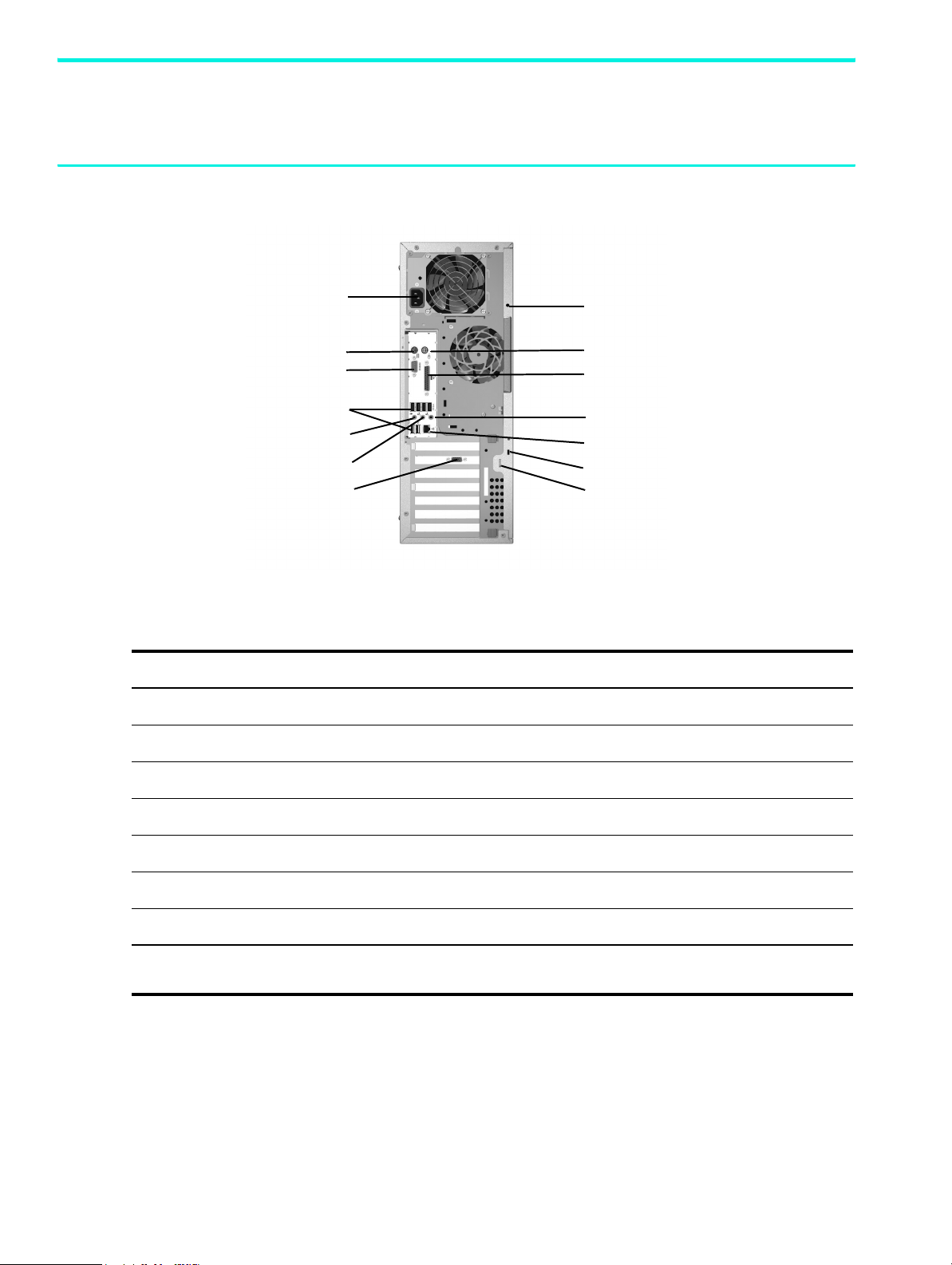
Figure 2-6 xw4200 Rear Panel Components
Table 2-5 xw4200 Rear Panel Components
Item Description Item Description
1 Power Cord Connector 8 Universal Chassis Clamp Opening
2 Keyboard Connector (purple) 9 Mouse Connector (green)
8
9
10
11
12
13
14
3 Serial Connector (teal) 10 Parallel Connector (burgundy)
4 USB Ports (6) 11 Audio Line-In Connector (light blue)
5 Microphone Connector (pink) 12 RJ-45 Network Connector
6 Audio Line-Out Connector (lime) 13 Cable Lock Slot
7 Graphics Adapter (blue) 14 Padlock Loop
NOTE: The rear panel connectors are labeled with industry-standard icons and colors to assist you in connecting your peripheral
devices.
Hardware Setup16
Page 17
xw6200 Rear Panel Components
1
2
6
7
8
9
10
11
3
4
5
12
13
14
15
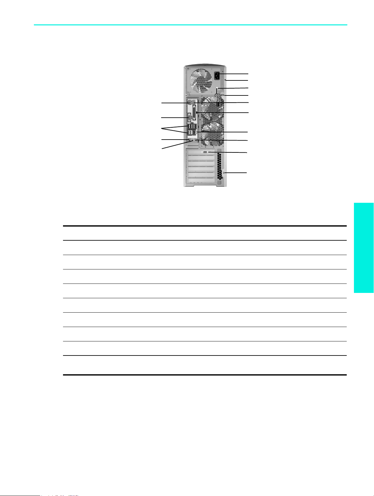
Figure 2-7 xw6200 Rear Panel Components
Table 2-6 xw6200 Rear Panel Components
Item Description Item Description
1 Keyboard Connector (purple) 9 Mouse Connector (green)
2 Serial Connector (teal) 10 Parallel Connector (burgundy
3 USB Ports (6) 11 RJ-45 Network Connector
4 Microphone Connector (pink) 12 Audio Line-In Connector (light blue)
5 Audio Line-Out Connector (lime) 13 Graphics Adapter (blue)
Hardware Setup
6 Power Cord Connector 14 Cable Lock Slot
7 Universal Chassis Clamp Opening 15 Mouse Connector (green)
8 Access Panel Key
NOTE: The rear panel connectors are labeled with industry-standard icons and colors to assist you in connecting your peripheral
devices.
Rear Panel Components 17
Page 18

xw8200 Rear Panel Components
8
1
9
10
11
2
12
13
3
4
5
6
14
15
16
7
Figure 2-8 xw8200 Rear Panel Components
Table 2-7 xw8200 Rear Panel Components
Item Description Item Description
1 Power Cord Connector 9 Access Panel Key
2 Keyboard Connector 10 Padlock Loop
3 Serial Connector (teal) 11 Cable Lock Slot
4 USB Ports (6) 12 Mouse Connector (green)
5 IEEE 1394 Connector 13 Parallel Connector (burgundy)
6 Microphone Connector (pink) 14 RJ-45 Network Connector
7 Audio Line-Out Connector (lime) 15 Audio Line-In Connector (light blue)
8 Universal Chassis Clamp Opening 16 Graphics Adapter (blue)
NOTE: The rear panel connectors are labeled with industry-standard icons and colors to assist you in connecting your peripheral
devices.
Hardware Setup18
Page 19

xw9300 Rear Panel Components
8
1
9
10
11
2
3
4
5
6
12
13
14
15
7
Figure 2-9 xw9300 Rear Panel Components
Table 2-8 xw9300 Rear Panel Components
Item Description Item Description
1 Power Cord Connector 9 Access Panel Key
2 Serial Connector (teal) 10 Padlock Loop
3 Keyboard Connector 11 Cable Lock Slot
4 USB Ports (4) 12 Mouse Connector (green)
5 IEEE 1394 Connector 13 RJ-45 Network Connector
6 Microphone Connector (pink) 14 Audio Line-In Connector (light blue)
7 Audio Line-Out Connector (lime) 15 Graphics Adapter (blue)
8 Universal Chassis Clamp Opening
NOTE: The rear panel connectors are labeled with industry-standard icons and colors to assist you in connecting your peripheral
devices.
Hardware Setup
Rear Panel Components 19
Page 20

Keyboard
1
8
7
2
586
3
4
Figure 2-10 Standard Keyboard
Table 2-9 Standard Keyboard Key Descriptions
Item Component Description
1 Function Keys Perform special functions, depending on the software application being used.
2 Editing Keys Includes Insert, Home, Page Up, Delete, End, and Page Down.
3 Status Lights Indicate the status of the workstation and keyboard settings
(Num Lock, Caps Lock, and Scroll Lock).
4 Numeric Keys Used like a calculator keypad.
5 Arrow Keys Used to navigate through a document or website. These keys allow you to move
left, right, up, and down, using the keyboard instead of the mouse.
6 Application Key* Used (like the right mouse button) to open pop-up menus in a Microsoft
application. May perform other functions in other software applications.
7 Windows® Logo Keys* Used to open the Start menu in Microsoft Windows. Used in combination with
other keys to perform other functions. (Available only on systems with Microsoft
Windows
pre-installed.)
8 Ctrl Key Used in combination with another key; its effect depends on the application
software you are using.
NOTE: * Keys available in select geographic regions.
™ Office
Hardware Setup20
Page 21

Using the Windows Logo Key
Use the Windows Logo key in combination with other keys to perform certain functions available in the
Windows operating system.
NOTE: The Windows logo key does not function on Linux systems.
Table 2-10 Windows Logo Key Functions
Key Description
Windows Logo Key Displays or hides the Start menu
Windows Logo Key + d Displays the Desktop
Windows Logo Key + m Minimizes all open applications
Shift + Windows Logo Key + m Undoes Minimize All
Windows Logo Key + e Launches My Computer
Windows Logo Key + f Launches Find Document
Windows Logo Key + Ctrl + f Launches Find Computer
Windows Logo Key + F1 Launches Windows Help
Windows Logo Key + l Locks the computer if you are connected to
a network domain, or allows you to switch
users if you are not connected to a network
domain
Windows Logo Key + r Launches the Run dialog box
Windows Logo Key + u Launches the Utility Manager
Windows Logo Key + Tab Activates the next Taskbar button
Special Mouse Functions
Most software applications support the use of a mouse. The functions assigned to each mouse button
depend on the software applications you are using.
NOTE: Some mouse software applications may interfere with the functionality of the keyboard and
mouse if the keyboard and mouse are connected to your workstation through a KVM (keyboard, video,
mouse) switch. If you are experiencing “no-response” from your keyboard and mouse, you may need to
uninstall the mouse software or connect the keyboard and mouse directly to the keyboard and mouse
connectors on the workstation.
Hardware Setup
Special Mouse Functions 21
Page 22
Serial Number and COA Label Location
Figure 2-11 Each workstation has two unique serial number labels 1 and a certificate of authentication
(COA) label 2 (for Windows-preinstalled systems only). In general, the serial number labels can be found
on the top panel or on the side of the unit and at the rear of the unit. Keep this number available for use
when contacting customer service for assistance. The COA label is generally located on the top panel or
access panel near the serial number label.
1
Figure 2-12 Serial Number and COA Label Locations
1
2
1
Hardware Setup22
Page 23

3Software Setup
CAUTION: Do not add optional hardware or third-party devices to the workstation until the operating
system is successfully installed. Doing so may cause errors and prevent the operating system from installing
correctly.
Installing and Customizing Windows XP Workstations
If your unit is a Windows–preinstalled workstation, follow the instructions in this section to setup up your
OS and software.
Starting up the Operating System
The first time you turn on the workstation, the operating system is installed automatically. This process takes
about 5 to 10 minutes. Carefully read and follow the instructions on the screen to complete the installation.
CAUTION: After the automatic installation has started, DO NOT TURN OFF THE WORKSTATION UNTIL
THE PROCESS IS COMPLETE. Turning off the workstation during the installation process may damage the
software that runs the workstation or prevent its proper installation.
NOTE: After you have selected a language during initial boot of the OS, the language will be locked in
by the UIA sector of their HDD. If the system is restored for some reason, the restore CD will check for the
language stored in the UIA and will restore only the original preinstalled language. In the case where a
new HDD is installed and the there is no UIA or the UIA is empty, then the Recovery CD will install any
language requested. If the wrong OS is accidently unbundled during the initial boot, technical support will
have to be contacted to get a “key” to unlock it and then you will be able to restore the OS to the correct
language.
A language selection is not required for the 64-bit operating system.
For complete operating system installation and configuration instructions, refer to the operating system
documentation that was provided with the workstation. Additional information is available in the online
help after you install the operating system.
Software Setup
Installing and Customizing Windows XP Workstations 23
Page 24

Restoring the Software
Restore the original operating system and factory-installed software by using the Restore Plus! CD and the
OS CD(s) that came with the workstation. Carefully read and follow the instructions provided with the
Restore Plus! CD.
NOTE: If you are restoring on a 64-bit operating system, you will be prompted for the second restore CD.
NOTE: If you restore your system using the Restore Plus! CD, some settings, such as your power
management settings (such as the Energy Star® settings) will need to be reapplied.
Installing or Upgrading Device Drivers
When installing optional hardware devices after the operating system installation is complete, you must
also install the drivers for each device.
If prompted for the I386 directory, replace the path specification with C:\i386, or use the
in the dialog box to locate the I386 folder. This action points the operating system to the appropriate
drivers.
NOTE: If the workstation has an optical RW drive, you must install the appropriate application to be able
to write to the drive. To install the application, use the optical software application CD and load the
appropriate applications.
Energy Star
The Energy Star® program is a government-backed initiative to promote energy efficiency by identifying
ways to reduce energy consumption at home or in the office. Select HP workstations participate in the
Energy Star program.
NOTE: Energy Star is not supported on Linux-based workstations.
For those workstations supporting Energy Star and have it enabled, the power management features will
be set as follows:
Browse button
• Monitor—goes into Standby mode after 20 minutes of inactivity.
• System—goes into Standby mode after 20 minutes of inactivity.
• Hard Drive—goes into power savings mode after the system goes into Standby mode.
NOTE: Should you have to restore the operating system, Energy Star settings (if applicable) will need to
be reset after the restore.
Software Setup24
Page 25

NOTE: For more information on Energy Star, refer to the Service and Technical Reference Guide web link
located on the Documentation and Diagnostics CD
(www.hp.com/support/workstation_manuals).
Accessibility
HP is committed to designing products, services, and programs with improved usability and accessibility
for all customers.
HP products with Microsoft Windows XP preinstalled are designed for accessibility, and these products are
tested with industry-leading Assistive Technology products.
HP Accessibility—connecting everyone to the power of technology.
Customizing the Monitor Display
You can manually select or change the monitor model, refresh rates, screen resolution, color settings, font
sizes, and power management settings. To do so, right-click on the Windows Desktop, then click
Properties to change display settings. For more information, refer to the online documentation provided
with the graphics controller utility or the documentation that came with your monitor.
Installing and Customizing
Linux–preinstalled Workstations
If you have a Linux-preinstalled workstation, follow the instructions in this section to setup up your OS and
software.
After the boot process completes, you can view additional HP Linux documentation by simply opening
your Internet browser (the browser is automatically set to use the local HP documentation page as its
default). You can also access Linux Web links for Red Hat (Internet access required) by using your Internet
browser.
NOTE: For additional information concerning the setup of Linux–preinstalled or Linux–enabled
workstations, refer to the
HP User Manual for Linux, located at www.hp.com/support/linux_user_manual
For additional information about HP and Linux, visit www.hp.com/linux.
.
Software Setup
Installing and Customizing Linux–preinstalled Workstations 25
Page 26

Starting up the Linux Operating System
The first time the workstation is booted, the Red Hat First Boot utility displays. This program allows you to
enter your password, network, graphics, time, and keyboard settings for your workstation.
CAUTION: Once the automatic installation has begun, DO NOT TURN OFF THE WORKSTATION UNTIL
THE PROCESS IS COMPLETE. Turning off the workstation during the installation process may damage the
software that runs the workstation or prevent its proper installation.
NOTE: When you enable the YPBind feature in the Network tab of the Linux Setup Tool, you may get a
blank screen for about 15-30 seconds after you have selected and saved all of your settings and have
exited the utility. This is normal. The boot process continues its execution after the screen returns.
Restoring the Linux Operating System
NOTE: To restore the Linux OS, the HP Driver CD and Red Hat box set are required.
Download the latest HP Driver CD to get any new enhancements.
Downloading the Latest HP Driver CD
To download the latest HP Driver CD:
1. Download the ISO image to a local hard drive from the HP support website for the appropriate
workstation platform (such as www.hp.com/support/xw4200
a. Click the download drivers and software link.
b. Select the Linux OS that matches your box set.
c. Select the latest version from the Utility Tools section.
d. Download and unpack it (tar zxvf filename.tgz).
2. Copy the ISO image to CD-R bootable media. On another Linux workstation, use the cdrecord
utility. Identify the device address for the CD burner (cdrecord --scanbus).
The default is usually 2, 0, 0.
Example:
cdrecord -v -eject dev=2,0,0 CD0_golden.iso
Installing with the HP Driver CD
).
To install with the HP Driver CD:
1. Boot the workstation from the Red Hat box set Binary CD 1.
2. Insert the Linux operating system CDs from the Red Hat box set as prompted.
3. Continue following the prompts until the operating system is successfully installed.
4. Configure the X server to start on reboot.
Software Setup26
Page 27

5. Reboot the workstation.
6. Follow the prompts to set up your system with the Red Hat First Boot utility.
7. When prompted in First Boot to add additional CDs, insert the HP Driver CD into the CD-ROM tray of
the workstation.
8. Click Install next to “Additional CDs.”
The HP Driver CD window opens.
9. Click Press to begin install...
10.When the install is done, you will have two options, “Reboot now...” on the left-side and “Press to
continue, reboot later...” on the right-side.
11.Click Reboot now...
Upgrading Device Drivers
If you need to upgrade a Linux device driver, visit the HP website at:
www.hp.com/go/workstationsupport
Installing and Customizing Linux–enabled
Workstations
Linux–enabled workstations are not pre-installed with Linux. They require the HP Installer Kit for Linux and
the purchase of a Red Hat box set. The Installer kit includes the HP CDs necessary to complete the
installation of all versions of the Red Hat box set which have been verified to work on HP workstation
hardware.
Verifying Hardware Compatibility
To see which Linux versions have been verified to work on HP workstation hardware:
1. Go to www.hp.com/support/workstation_manuals
2. Select your HP workstation model.
3. Click the Hardware Support Matrix for Linux link.
Installing the Linux Operating System
.
Software Setup
To install the Linux operating system on your Linux–enabled system:
1. Follow the instructions for Restoring the Linux Operating System in the previous section.
2. Follow the instructions for Starting up the Linux Operating System in the previous section.
NOTE: For additional information concerning the setup of Linux–preinstalled or Linux–enabled
workstations, refer to the HP User Manual for Linux, located at www.hp.com/support/linux_user_manual
For additional information about HP and Linux, visit www.hp.com/linux.
Installing and Customizing Linux–enabled Workstations 27
.
Page 28

Upgrading Device Drivers
If you need to upgrade a Linux device driver, visit the HP website at:
www.hp.com/go/workstationsupport
After First-Boot
After successfully booting your system for the first time, HP recommends you do the following:
• Verify you have the latest system BIOS loaded by visiting http://welcome.hp.com/country/us/en/
support.html. See Upgrading the BIOS later in this chapter for more details.
• Verify you have the latest drivers for your system by visiting http://welcome.hp.com/country/us/en/
support.html.
• Review the Preface of this document to become familiar with your available HP resources.
Also, consider the following:
• Subscribe to Driver Alerts at www.hp.com/subscriberchoice
• Purchase a subscription to the Support Software CD kit. See the Subscribing to Software Support later
in this chapter for ordering information.
Hyper-Threading Technology
Hyper-Threading Technology is a high performance technology, developed by Intel®, that allows a single
processor to execute multiple threads of instructions simultaneously. Hyper-Threading Technology enables
the Intel processor to utilize its execution resources more efficiently, delivering performance increases and
improving user productivity. Not all system applications benefit from the Hyper-Threading Technology. Not
all systems support Hyper-Threading Technology.
To see if Hyper-Threading Technology can benefit you, test your system by turning the feature on. The BIOS
setup menu can be used to turn this feature on or off. To do this, run the BIOS setup during boot up and
select Advanced > Device Options > Hyper-Threading, then choose whether to enable or disable the
Hyper-Threading Technology.
NOTE: If your workstation does not support Hyper-Threading Technology, the Hyper-Threading menu item
will not be available on the Computer Setup menu.
.
NOTE: To enable hyper–threading, Linux systems require the latest system BIOS and an SMP kernel (for
systems installed with a single processor). For additional information concerning the setup of
Linux–preinstalled or Linux–enabled workstations, refer to the
HP User Manual for Linux, located at www.hp.com/support/linux_user_manual.
For more information about the Hyper-Threading Technology, you can visit the Intel® website at
www.intel.com
Software Setup28
.
Page 29

Turning off the Workstation
To properly turn off the workstation, first shut down the operating system software.
CAUTION: Manually forcing the workstation off can cause loss of data.
To manually turn off power to the workstation, press and hold the power button for four seconds. However,
manually turning off the power bypasses the standby state and can result in loss of data.
To reconfigure the power button to work in On/Off mode, run Computer Setup (F10). Refer to the Service
and Technical Reference Guide web link located on the Documentation and Diagnostics CD
(www.hp.com/support/workstation_manuals
) for more information about using Computer Setup.
Upgrading the BIOS
After the first boot, it is a good practice to verify your system is operating with the latest BIOS.
To check the current BIOS on the system, press F10 during POST. At the end of POST, the F10 Setup Utility
displays and lists the BIOS version under File > System Information.
To check the latest BIOS available:
1. Access the HP website at http://welcome.hp.com/country/us/en/support.html
& Drivers page.
2. Select the Download drivers and software option and enter the system model number (such as
xw8200) and press Enter.
NOTE: If variations of the model are found, you will be asked to select a more specific model.
3. From the product page, select the appropriate operating system.
4. From the Select a Category area, click the BIOS link and note the version of the latest system BIOS.
If the BIOS on the website is the same as the version on the system, no further action is required.
If the BIOS on the website is a later version, then flash the system BIOS using the later version.
1. From the HP website, click the Download button next to the appropriate system BIOS.
2. From the File Download window, click Open.
3. From the InstallShield Wizard window, click Next.
4. Accept the license agreement and click Next.
5. Enter the location where you want the files to be saved to. Click Next.
At this point, there are several options available to flash the system BIOS. You can save the files to
bootable devices such as a 3.5 inch diskette, a CD-ROM, or a USB device. The shortest and most efficient
way is to use the HPQFlash utility that is available on your system.
to access the Support
Software Setup
To run HPQFlash, browse to the folder where you saved the BIOS softpaq earlier. Locate and click on the
HPQFlash.exe file to initiate the HPQFlash utility. Follow the on-screen instructions. The current system
BIOS and the system BIOS that is about to be loaded is displayed. You will be notified after the BIOS flash
is complete.
Turning off the Workstation 29
Page 30

Subscribing to Software Support
You can also obtain the latest support software through a subscription to the Support Software CD Kit
using the Support Software Management order form available at the following website:
http://h18007.www1.hp.com/support/files/workstations/us/purchase.html
HP ProtectTools Embedded Security
The HP ProtectTools Embedded Security solution includes the following key components:
• ProtectTools Embedded Security – a hardware module, known as the Trusted Platform Module (TPM),
that is integrated in the computer system itself
• ProtectTools Embedded Security Manager – this software has three key functions:
• Controlling the basic operation of ProtectTools Embedded Security (enabling, ownership, and
more)
• Enhancing file and folder encryption capabilities
• Supporting protected digital certificate operations for many existing applications such as Microsoft
Outlook or Netscape Messenger
HP ProtectTools Embedded Security is a hardware security chip that offers security and encryption features
and provides a tamper-proof storage area for protecting public and private keys. The chip is factoryinstalled and should not be accessed or removed except by HP authorized service providers.
It is critical to do a backup of the Embedded Security credentials if data is being encrypted with the
Embedded Security chip. The backup is required to restore your settings and data whenever the system
board or Embedded Security chip is changed. To perform the backup, use the HP ProtectTools Embedded
Security Backup Wizard that is part of the HP ProtectTools Security Manager utility.
Software Setup30
Page 31

4Troubleshooting
Self Troubleshooting
This section provides some self-help tools and troubleshooting tables that you can use to troubleshoot your
system.
HP Insight Diagnostics
HP Insight Diagnostics is an offline diagnostic utility that allows you to perform system testing. With this
utility, you can test your system hardware and view the hardware configuration information for your
system.
To use the HP Insight Diagnostics utility, insert the Documentation and Diagnostics CD into your system and
reboot. Follow the onscreen menu options and directions to begin your testing.
NOTE: Should you not have the Documentation and Diagnostics CD available, you can download the
image from www.hp.com/go/workstationsupport
1. Click on your workstation model link then click the download drivers and software link.
2. Select your language and then click the appropriate operating system link.
3. From the download drivers and software screen, click the Diagnostics link and then click the
appropriate diagnostic program link.
.
For more information on using HP Insight Diagnostics, click the Help tab from within the program or refer
to the Service and Technical Reference Guide web link located on the Documentation and Diagnostics
CD.
HP Troubleshooting Resources and Tools
HP Help and Support Center
The HP Help and Support Center is a customized HP user interface that enhances the Windows XP Help
and Support Center Help feature. This customized utility allows you to access specific information about
your HP workstation such as configuration information by clicking Start > Help and Support Center. The
interface also provides customized help and support links to the HP website related to your HP
workstation.
Self Troubleshooting 23
Troubleshooting
Page 32

High Performance Tuning Framework
HP Performance Tuning Framework enables optimal configuration of HP Personal Workstations delivering
stability and best performance.
HP Performance Tuning Framework will guide your system setup allowing a “custom” configuration that
best matches the workstation to user requirements. This customization ensures availability of the latest
graphics cards and drivers and removes some memory restraints.
The Framework's extensible design permits new configuration functionality and application support to be
easily integrated over time. To facilitate the delivery of such new features, the Framework automatically
updates itself when newer versions become available.
For more information about HP Performance Tuning Framework and instruction on how to use it, visit
http://www.hp.com/workstations/software/framework/index.html
E-Support
For online access to technical support information and tools, go to www.hp.com/support. Support
resources include web-based troubleshooting tools, technical knowledge databases, driver and patch
downloads, online communities, and proactive notification services.
The following sites are also available to you.
• www.hp.com
• www.hp.com/support/workstation_manuals
• http://www.hp.com/go/workstationsupport
workstation.
• http://welcome.hp.com/country/us/eng/wwcontact.html
technical support phone numbers.
Troubleshoot a Problem
To help you troubleshoot issues with your system, HP provides the Business Support Center (BSC). The BSC
is a portal to an extensive selection of online tools. To access the BSC, visit www.hp.com/go/
workstationsupport. Select your product by clicking on the appropriate product link.
—Provides useful product information.
.
—Provides the latest online documentation.
—Provides technical support information for your
—Provides a listing of the worldwide
From the left-hand Business Support Center menu window, select the troubleshoot a problem link. From the
troubleshoot a problem page, select the appropriate link from under the useful documents area.
Instant Support/Active Chat
HP Instant Support is a set of Web-based support tools that automate and speed the resolution of desktop
computing, tape storage and printing problems.
Active Chat enables you to electronically submit a support ticket to HP over the Web. When you submit a
support ticket, Active Chat will collect information about the computer and pass it to an online support
specialist. The collection of information may take up to 30 seconds depending on the computer
configuration. Once you have submitted a support ticket, you will receive a confirmation message
containing your case ID, the support hours for your location and the estimated time of response.
Fore more information about HP Instant Support and Active Chat and how to use them, visit HP at http://
www.hp.com/hps/hardware/hw_professional.html.
Troubleshooting24
Page 33

Customer Advisories
Customer advisories provide clients important information about their system. To search for applicable
customer advisories for your system, visit www.hp.com and use the search tool. To maximize your search
efforts, use the “+” symbol to locate valid words. For example, to search for customer advisories for the
xw8200, enter “+xw6000 +customer +advisory” and hit Enter. You can also use the “-” (minus) symbol to
exclude certain words. You can also register Subscribers Choice to automatically receive PCNs related to
your system. Review the preface of this guide for information on how to register to Subscriber’s Choice.
Product Change Notifications
Product Change Notifications (PCNs) provide customers with a notice of changes to their product. You can
visit www.hp.com and perform a search for PCNs related to your system. You can also register Subscribers
Choice to automatically receive PCNs related to your system. Review the preface of this guide for
information on how to register to Subscriber’s Choice.
Helpful Hints
If you encounter some minor problem with your workstation, monitor, or software, refer to the following list
of general suggestions before taking further action.
At Startup
• Check that the workstation and monitor are plugged into a working electrical outlet.
• Remove all diskettes from your system before turning it on.
• Check to see that the workstation is turned on and the green power light is on.
• If you have installed an operating system other than the factory-installed operating system, check to be
sure that it is supported on your system.
• Check to see that the monitor is turned on and the green monitor light is on.
• Turn up the brightness and contrast controls of the monitor if the monitor is dim.
• If your workstation has multiple video sources installed and a single monitor, the monitor must be
connected to the monitor connector on the source selected as the primary VGA adapter. During
startup, the other monitor connectors are disabled; if the monitor is connected into one of these ports,
it will not function. You can select the default VGA source in Computer Setup (F10).
During Operation
• Look for blinking LEDs on the front of the workstation. The blinking lights are error codes that will help
you diagnose the problem. See the interpreting diagnostic lights and audible codes sections in this
chapter for more information.
• Press and hold any key. If the system beeps, then your keyboard is operating correctly.
• Check all cable connections for loose connections or incorrect connections.
• Wake the workstation by pressing any key on the keyboard or the power button. If the system remains
in suspend mode, shut down the system by pressing and holding the power button for at least four
seconds, then press the power button again to restart the system. If the system will not shut down,
unplug the power cord, wait a few seconds, then plug it in again. If it does not restart automatically,
press the power button to start the workstation.
• Reconfigure your workstation after installing a non–plug and play expansion board or other option.
See Hardware Installation Problems for instructions.
HP Troubleshooting Resources and Tools 25
Troubleshooting
Page 34

• Be sure that all the needed device drivers have been installed. For example, if you have connected a
printer, you need to install a printer driver.
• If you are working on a network, plug another workstation with a different cable into the network
connection. There may be a problem with the network plug or cable.
• If you recently added new hardware, remove the hardware and see if the workstation functions
properly.
• If you recently installed new software, uninstall the software and see if the workstation functions
properly.
• If the screen is blank, plug the monitor into a different video port on the workstation if one is available.
Or, change out the monitor with a monitor that you know is working properly.
• For more detailed information, refer to the troubleshooting chapter in the Service and Technical
Reference Guide web link located on the Documentation and Diagnostics CD.
POST Error Messages
You can also find additional information about POST error messages in the Service and Technical
Reference Guide for your workstation. The Service and Technical Reference Guide is available as a Web
link located on the Documentation and Diagnostics CD (www.hp.com/support/workstation_manuals
).
Basic Troubleshooting
This section concentrates on problems that you might encounter during the initial set up process.
Additional troubleshooting information is available in the Service and Technical Reference Guide web link
located on the Documentation and Diagnostics CD and at the following HP website:
www.hp.com/go/workstationsupport
General Problems
You may be able to easily resolve the general problems described in this section. If a problem persists and
you are unable to resolve it yourself or if you feel uncomfortable about performing the operation, you can
contact an HP customer care center, or you can contact an authorized dealer or reseller. For a list of
support telephone numbers for your region, visit the HP website at:
http://welcome.hp.com/country/us/eng/wwcontact.html
Table 4-11 Troubleshooting General Problems
Problem Cause Solution
Workstation appears locked up and
will not turn off when the power
button is pressed.
.
Software control of the power switch
is not functional.
.
Press and hold the power button for at
least four seconds until the workstation
turns off.
Workstation will not respond to USB
keyboard or mouse.
CAUTION: When attempting to resume from standby mode, do not hold down the power button for more than four
seconds. Otherwise, the workstation will shut down and you will lose your data.
Troubleshooting26
Workstation is in standby mode. Press the power button to resume from
standby mode.
Page 35

Table 4-11 Troubleshooting General Problems
Problem Cause Solution
Workstation date and time display is
incorrect.
Workstation appears to pause
periodically.
Cursor will not move using the arrow
keys on the keypad.
Cannot remove workstation cover or
access panel.
RTC (real-time clock) battery may
need to be replaced.
NOTE: Connecting the workstation to
a live AC outlet prolongs the life of the
RTC battery.
Network driver is loaded and no
network connection is established.
The Num Lock key may be on. Press the Num Lock key. The
Solenoid hood lock, featured on some
systems, is locked.
First, reset the date and time using
Computer Setup (F10). If the problem
persists, replace the RTC battery. See
the Service and Technical Reference
Guide for instructions on installing a
new battery, or contact an authorized
dealer or reseller for RTC battery
replacement.
Establish a network connection, or use
Computer Setup (F10) to disable the
network controller.
Num Lock light should not be on if
you want to use the arrow keys. The
Num Lock key can be disabled (or
enabled) in Computer Setup (F10).
Unlock the solenoid hood lock using
Computer Setup (F10). The solenoid
hood lock FailSafe Key, a device for
manually disabling the solenoid hood
lock, is available from HP. You will
need the FailSafe Key in case of
forgotten password, power loss, or
workstation malfunction. (Not
applicable to the xw8200 and
xw9300)
The panel is locked. (xw6200,
xw8200, and xw9300)
Poor performance is experienced. Processor is hot. 1. Make sure the airflow to the
Hard drive is full. Transfer data from the hard drive to
Use the key located on the back of the
unit to unlock the panel.
workstation is not blocked.
2. Make sure the fans are connected
and working properly.
3. Make sure the processor heatsink
is installed properly.
create more space on the hard drive.
Basic Troubleshooting 27
Troubleshooting
Page 36

Table 4-11 Troubleshooting General Problems
Problem Cause Solution
Workstation powered off
automatically and the Power LED
blinks Red two times, once every
second, followed by a two second
pause. (On the xw4200 and
xw9300, two audible beeps will also
be emitted.)
System does not power on and the
LEDs on the front of the workstation
are not blinking.
Processor thermal protection
activated:
A fan may be blocked or not turning.
OR
The heatsink is not properly attached
to the processor.
System unable to power on. Press and hold the power button for
1. Ensure that the workstation air
vents are not blocked and the
cooling fan is running.
2. Open hood, press power button,
and see if the processor fan spins.
If the processor fan is not
spinning, make sure the fan's
cable is plugged onto the system
board header. Ensure the fan is
fully/properly seated or installed.
3. If fan is plugged in and seated
properly, but is not spinning, then
replace the processor heatsink
assembly.
4. Reseat processor heatsink and
verify that fan assembly is
properly attached.
5. Contact an authorized reseller or
service provider.
less than 4 seconds. If the hard drive
LED turns green, then:
1. Remove the expansion cards one
at a time and try holding the
power button again for less than
4 seconds.
2. Replace the system board.
OR
Press and hold the power button for
less than 4 seconds. If the hard drive
LED does not turn on green then:
1. Check that unit is plugged into a
working AC outlet.
2. Open hood and check that the
power button harness is properly
connected to the system board.
3. Check that both power supply
cables are properly connected to
the system board.
4. Check the Power Supply Built-In-
Self-Test (BIST) LED located inside
the power supply (look directly at
the rear of the chassis).
5. Replace the system board.
Troubleshooting28
Page 37

Hardware Installation Problems
You may need to reconfigure the workstation when you add or remove hardware, such as an additional
diskette drive. If you install a plug and play device, some operating systems automatically recognize the
device and configure the workstation. If you install a non–plug and play device, you must reconfigure the
workstation after installing the new hardware.
Table 4-12 Troubleshooting Hardware Installation Problems
Problem Probable Cause Recommended Solution
A new device is not recognized
as part of the system.
Workstation will not start. Wrong memory modules were
Device is not seated or connected
properly.
Cable(s) of new external device
are loose or power cables are
unplugged.
Power switch of new external
device is not turned on.
When the system advised you of
changes to the configuration, you
did not accept them.
A plug and play board may not
automatically configure when
added if the default configuration
conflicts with other devices.
used in the upgrade or memory
modules were installed in the
wrong location.
Ensure that the device is properly and securely
connected and that pins in the connector are not
bent down.
Ensure that all cables are properly and securely
connected and that pins in the cable or
connector are not bent down.
Turn off the workstation, turn on the external
device, then turn on the workstation to integrate
the device with the workstation system.
Reboot the workstation and follow the
instructions for accepting the changes.
Use Computer Setup (F10) to reconfigure or
disable devices to resolve the resource conflict.
1. Review the documentation that came with
the system to determine if you are using the
correct memory modules and to verify the
proper installation.
2. Observe the beeps and LED lights on the
front of the workstation. See “Interpreting
Diagnostic Lights and Audible Codes” to
determine possible causes.
3. If you still cannot resolve the issue, contact
Customer Support.
Power LED blinks Red five
times, once every second,
followed by a two second
pause, and the workstation
beeps five times.
Power LED blinks Red six times,
once every second, followed
by a two second pause, and
the workstation beeps six
times.
Memory is installed incorrectly or
is bad.
Video card is not seated properly
or is bad, or system board is bad.
1. Reseat DIMMs. Power on the system.
2. Replace DIMMs one at a time to isolate
faulty module.
3. Replace third-party memory with HP
memory.
4. Replace the system board.
For systems with a graphics card:
1. Reseat the graphics card. Power on the
system.
2. Replace the graphics card.
3. Replace the system board.
Troubleshooting
Basic Troubleshooting 29
Page 38

Diagnostic Lights and Audible (Beep) Codes
This section covers the front panel light (LED) error and operation codes as well as the audible codes that
may occur before or during the Power-On Self-Test (POST).
Table 4-13 Diagnostic Lights and Audible Codes
Activity Beeps Possible Cause Recommended Action
Green Power LED On. None Workstation on. None
Green Power LED blinks every
two seconds.**
Green Power LED is off.** None Workstation in Suspend
Green Power LED blinks three
times, once per second.**
Green Power LED blinks four
times, once per second.**
NOTE: **When the Unique Sleep State Blink Rates is disabled in Computer Setup (F10), these reflexes are
observed on the green power LED.
NOTE: For the following LED activity and beeps, the beeps will be heard through the on–board speaker and not the
chassis speaker. Blinks and beeps will be repeated for 5 cycles, after that, only the blinks will continue to repeat.
Red Power LED blinks two
times, once every second,
followed by a two- second
pause.
None Workstation in Suspend to RAM
mode (select models only) or
normal Suspend mode.
to Disk or “Hibernate” mode.
None Workstation in Suspend to RAM
mode (select models only) or
normal Suspend mode.
None Workstation in Suspend
to Disk or “Hibernate” mode.
2 (only on
xw4200
and
xw9300)
Processor thermal protection
activated:
A fan may be blocked or not
turning.
OR
The heatsink/fan assembly is not
properly attached to the
processor.
None
None
None
None
1. Ensure that the workstation air
vents are not blocked and the
cooling fan is running.
2. Open hood, press power button,
and see if the processor fan spins.
If the processor fan is not
spinning, make sure the fan's
cable is plugged onto the system
board header. Ensure the fan is
fully/properly seated or installed.
3. If fan is plugged in and seated
properly, but is not spinning, then
replace processor fan.
4. Reseat processor heatsink and
verify that fan assembly is
properly attached.
5. Contact an authorized reseller or
service provider.
Red Power LED blinks three
times, once every second,
followed by a two- second
pause.
Troubleshooting30
3 (only on
xw4200
and
xw9300)
Processor not installed (not an
indicator of bad processor).
1. Check to see that the processor is
present.
2. Reseat the processor.
Page 39

Table 4-13 Diagnostic Lights and Audible Codes
Activity Beeps Possible Cause Recommended Action
NOTE: For the following LED activity and beeps, the beeps will be heard through the on–board speaker and not the
chassis speaker. Blinks and beeps will be repeated for 5 cycles, after that, only the blinks will continue to repeat.
Red Power LED blinks four
times once every second,
followed by a two-second
pause.(only on xw4200 and
xw9300)
Red Power LED blinks five
times, once every second,
followed by a two-second
pause.
4 Power failure (power supply is
overloaded)
5 Pre-video memory error 1. Reseat DIMMs. Power on the
1. Open the hood and ensure the 4-
wire (xw4200) or the 8-pin/wire
(xw6200, xw8200, and
xw9300) power supply cable is
seated into the connector on the
system board.
2. Check if a device is causing the
problem by removing ALL
attached devices (such as hard,
diskette, or optical drives, and
expansion cards.) Power on the
system. If the system enters the
POST, then power off and replace
one device at a time and repeat
this procedure, until failure
occurs. Replace the device that is
causing the failure. Continue
adding devices one at a time to
ensure all devices are functioning
properly.
3. Replace the power supply.
4. Replace the system board.
system.
2. Replace DIMMs one at a time to
isolate faulty module.
3. Replace third-party memory with
HP memory.
4. Replace the system board.
Red Power LED blinks six
times, once every second,
followed by a two-second
pause.
Red Power LED blinks seven
times, once every second,
followed by a two- second
pause.
6 Pre-video graphics error. For systems with a graphics card:
1. Reseat the graphics card. Power
on the system.
2. Replace the graphics card.
3. Replace the system board.
7 System board failure (ROM
detected failure prior to video).
Replace the system board.
Basic Troubleshooting 31
Troubleshooting
Page 40

Table 4-13 Diagnostic Lights and Audible Codes
Activity Beeps Possible Cause Recommended Action
NOTE: For the following LED activity and beeps, the beeps will be heard through the on–board speaker and not the
chassis speaker. Blinks and beeps will be repeated for 5 cycles, after that, only the blinks will continue to repeat.
Red Power LED blinks eight
times, once every second,
followed by a two-second
pause.
Red Power LED blinks nine
times, once every second,
followed by a two-second
pause.
System does not power on
and LEDs are not blinking.
8 Invalid ROM based on bad
checksum.
9 System powers on but does not
boot.
None System unable to power on. Press and hold the power button for
1. Reflash the ROM using a
ROMPaq diskette. See the “ROM
Flash” section of the Service and
Technical Reference Guide web
link located on the
Documentation and Diagnostic
CD
www.hp.com/support/
workstation_manuals
2. Replace the system board.
less than 4 seconds. If the hard drive
LED turns green, then:
1. Remove the expansion cards one
at a time and try holding the
power button again for less than
4 seconds.
2. Replace the system board.
OR
s
Press and hold the power button for
less than 4 seconds. If the hard drive
LED does not turn on green then:
1. Check that unit is plugged into a
working AC outlet.
2. Open hood and check that the
power button harness is properly
connected to the system board.
3. Check that both power supply
cables are properly connected to
the system board.
4. Check the Power Supply Built-In-
Self-Test (BIST) LED located inside
the power supply (look directly at
the rear of the chassis).
5. Replace the system board.
Troubleshooting32
Page 41

Calling Technical Support
At times you may encounter an issue that requires technical support. If after using the self-troubleshooting
tools you still cannot resolve your issue, note the following to help you locate the necessary information
that will assist technical support in resolving the situation.
• Be in front of your workstation when you call.
• Write down the workstation and monitor (if equipped) serial numbers, product numbers, model names,
and model numbers before calling and have them readily available.
• Note any applicable error messages.
• Note any add-on options.
• Note the operating system.
• Note any third-party hardware or software.
• Note any blinking LEDs on the front of the workstation.
• Note the applications you were using when you noted the issue.
• Be prepared to spend the time necessary troubleshooting the problem with the service technician.
NOTE: When calling in for service or support, you may be asked for the Product Number (example:
P8814A) of your workstation. If your workstation has a Product Number, it is generally located next to the
10- or 12-digit Serial Number of your workstation.
NOTE: See “Serial Number and COA Label Location” on page 22. for the location of the Serial Number
label on your workstation. In general, the Serial Number and Product Number label are located at the
rear of the workstation.
To contact technical support, call 1-800-HPINVENT or visit http://welcome.hp.com/country/us/eng/
wwcontact.html for a listing of the worldwide technical support phone numbers.
Calling Technical Support 33
Troubleshooting
Page 42

Troubleshooting34
Page 43

A Features and Accessories
Security Features
The following security features are available for your workstation.
• solenoid hood lock—this is an optional software-controllable cover lock, controlled by the setup
password, that prevents unauthorized access to the internal components.
NOTE: This feature is not available on the xw8200 or xw9300.
• cable lock provision—your workstation is equipped with a cable lock slot for an optional cable lock.
This allows you to secure the unit to a fixed or heavy object such as a desk.
• padlock loop—your workstation has a standard padlock loop available so that you can secure the
access panel to the system chassis with a padlock.
• access panel lock—on some workstations, the access panel comes with a keylock to prevent internal
access to your system. The keys for the keylock are located on the back of your workstation.
• universal chassis clamp lock—all workstations support this optional custom designed
all-in-one locking solution that protects the internal components while securing the monitor, keyboard,
mouse or speaker cables.
• port security bracket—the xw4200 supports this option that guards against the removal of any of the
I/O components connected to the main I/O back panel of your system.
For more information about these features, see the back panel illustrations earlier in this guide or refer to
the Service and Technical Reference Guide web link located on the Documentation and Diagnostics CD
(www.hp.com/support/workstation_manuals
).
Features and Accessories A
Chassis Conversion Features
The xw4200 is a convertible minitower (CMT) systems. It can be physically reconfigured from a minitower
orientation into a desktop orientation (or from a desktop to a minitower). For information and procedures
on converting your system, refer to the Service and Technical Reference Guide web link located on the
Documentation and Diagnostics CD
(www.hp.com/support/workstation_manuals
).
Security Features 35
Page 44

Accessories
The HP xw series workstations can be enhanced with several HP accessories. Some of these options
include:
• graphics cards
• memory
• diskette drives
• optical drives
• hard drives
• processors
• audio cards
Visit www.hp.com/workstations/pws/options
also tests certain options that are available from supported third-party suppliers. Refer to the Service and
Technical Reference Guide by using the link on the Documentation and Diagnostics CD (www.hp.com/
support/workstation_manuals) for instructions on installing and removing components.
for more information on available workstation options. HP
Features and Accessories36
Page 45

Index
A
access panel key 17, 18, 19
accessibility 25
accessories 44
audible codes 38
C
cable lock
description 43
slot location 16, 17, 18, 19
CD-ROM drive
See optical drive
COA label location 22
D
device drivers
Linux 26, 27, 28
Windows 24
diagnostic lights 38
diskette drive
activity light 13
eject button 13
location 13, 14
DVD-ROM drive
See optical drive
E
Energy Star 24
e-support 32
F
features
chassis conversion 43
security 43
G
graphics adapter location 16, 17,
18, 19
H
hard drive activity light 13, 14, 15
hardware setup 11
headphone jack location 13, 14,
15
helpful hints 33
HP Help and Support Center 31
HP Insight Diagnostics 31
Hyper-Threading Technology 28
I
IEEE-1394 connector location 13,
14, 15, 18, 19
K
keyboard
connecting 11
connector location 16, 17, 18,
19
L
line-in connector location 16, 17,
18, 19
line-out connector location 16, 17,
18, 19
Linux operating system
additional information 25
enabled 27
hardware compatibility 27
hyper-threading 28
installing 27
latest drivers 26
preinstalled 25
restoring 26
starting up 26
M
microphone connector location 13,
14, 15, 16, 17, 18, 19
monitor
connecting 11
customizing display 25
troubleshooting 33
mouse
connecting 11
connector location 16, 17, 18,
19
special functions 21
N
network connector location 16,
17, 18, 19
O
operating system
Linux 25
Windows 23
optical drive
activity light 13, 14, 15
eject button 13, 14, 15
installing software 24
location 13, 14, 15
P
padlock loop
description 43
location 16
parallel connector location 16, 17,
18
parts 7
power
button 13, 14, 15
light 13, 14, 15
power cord
connecting 11
location 16, 17, 18, 19
printer, connecting 11
Product Bulletin 7
R
regulatory information 7
S
security features
access panel lock 43
cable lock 43
padlock loop 43
port security bracket 43
solenoid hood lock 43
universal chassis clamp lock 43
serial connector location 16, 17,
18, 19
serial number location 22
software
restoring
Linux 26
Windows 24
T
technical support 41
troubleshooting
audible codes 38
basic 34
e-support 32
general problems 34
helpful hints 33
HP Help and Support Center 31
HP Insight Diagnostics 31
self 31
turning off the workstation 29
Index
Index 45
Page 46

U
universal chassis clamp
description 43
opening location 16, 17, 18,
19
USB ports
front panel location 13, 14, 15
rear panel location 16, 17, 18,
19
W
Windows operating system
additional information 23
language selection 23
preinstalled 23
restoring 24
Index46
 Loading...