

Page 1
crystal.bk : cover.fb4 Page 1 Monday, March 23, 1998 6:05 AM
HP Kayak XU & XW
PC Workstations
User’s Guide
Page 2

crystal.bk : notice.fb4 Page ii Monday, March 23, 1998 6:05 AM
Notice
The information contained in this document is subject to change without
notice.
Hewlett-Packard makes no warranty of any kind with regard to this material,
including, but not limited to, the implied warranties of merchantability and
fitness for a particular purpose. Hewlett-Packard shall not be liable for errors
contained herein or for incidental or consequential damages in connection with
the furnishing, performance, or use of this material.
Hewlett-Packard assumes no responsibility for the use or reliability of its
software on equipment that is not furnished by Hewlett-Packard.
This document contains proprietary information that is protected by copyright.
All rights are reserved. No part of this document may be photocopied,
reproduced, or translated to another language without the prior written
consent of Hewlett-Packard Company.
AccelGraphics and AccelEclipse are trademarks of AccelGraphics, Inc.
Adaptec® is a registered trademark of Adaptec, Inc. RAIDport
ArrayConfig
TM
, AROTM, CI/O
TM
and
Array1000 are trademarks of Adaptec, Inc.
TM
,
Adobe® Reader © 1987-1997 Adobe Systems Incorporated. All rights reserved.
Adobe and Acrobat are trademarks of Adobe Systems Incorporated.
CompuServe® is a registered trademark of CompuServe Incorporated.
Labtec® is a registered trademark of Labtec Enterprises, Inc.
Matrox® is registered trademark of Matrox electronic Systems Ltd.
TM
is a trademark of Matrox Graphics, Inc.
MGA
Symbios Logic
TM
is a trademark of Symbios Logic, Inc.
Microsoft® is a U.S. registered trademark of Microsoft Corporation. Windows
is a trademark of Microsoft Corporation.Windows NT® is a registered
trademark of Microsoft Corporation.
Netscape® is a trademark of Netscape Communications Corporation.
Pentium
SoundBlaster
SCSISelect
Hewlett-Packard France
Performance Desktop Computing Operation
38053 Grenoble Cedex 9
France
TM
is a trademark of Intel Corporation.
TM
is a trademark of Creative Technology Limited.
TM
is a trademark of Adaptec Incorporated
1998 Hewlett-Packard Company
TM
Page 3

crystal.bk : title.fb4 Page iii Monday, March 23, 1998 4:09 AM
User’s Guide
Page 4

crystal.bk : title.fb4 Page iv Monday, March 23, 1998 4:09 AM
Welcome to Your HP Kayak XU & XW PC Workstations
Congratulations on the purchase of your new Hewlett-Packard
Kayak XU or XW PC Workstation. These high-performance PC
Workstations are equipped with:
One or two PentiumTM II processors, with 100 MHz bus support, in
•
slots for easy processor upgrading.
Intel 440BX AGPset optimized for Pentium II for concurrent
•
transactions through the processor bus, AGP bus, PCI bus, and
memory.
Processor-integrated level-two cache for improved performance.
•
64 MB or 128 MB of 100 MHz SDRAM ECC (error correcting code)
•
DIMM memory, upgradeable to 1GB.
A high performance 2D graphics solution (XU models) or a state-of-
•
the-art 3D graphics solution that supports OpenGL acceleration (XW
models).
HP MaxiLife for top reliability and maximized uptime, ensuring
•
smooth and trouble-free functioning.
An integrated Ultra ATA/33 controller on the PCI bus supporting the
•
fastest IDE devices.
An integrated UltraWide 16-bit SCSI controller on the PCI bus (data
•
transfer rate of up to 40 MB per second) dedicated to internal hard
disk drives (HDDs).
An UltraWide 16-bit SCSI accessory board controller for external
•
peripherals (data transfer rate of up to 40 MB per second) and 8-bit
Ultra SCSI connectivity for internal devices (up to 20 MB per
second).
A RAIDport™ connector for acceleration of Internal UltraWide
•
16-bit SCSI channel with one or two hard disks.
A 32-bit PCI 10BT/100TX autosensing Ethernet LAN controller with
•
remote power-on and wake-up capability.
iv English
Page 5

crystal.bk : title.fb4 Page v Monday, March 23, 1998 4:09 AM
Seven mass storage shelves:
•
❒ Five front-access shelves
❒ Two internal shelves.
Six slots for accessory boards:
•
❒ One AGP (Accelerated Graphics Port) slot
❒ Three 32-bit PCI (Peripheral Component Interconnect) slots
❒ One 16-bit ISA (Industry Standard Architecture) slot
❒ One combination ISA or PCI slot.
A CD-ROM drive.
•
An integrated 16-bit full duplex high fidelity audio interface.
•
An HP enhanced keyboard.
•
For XU models — an HP enhanced mouse with scroll wheel that
•
enables you to scroll without using the scroll bars.
For XW models — an HP enhanced 3-button mouse with added
functionality when used with certain Windows NT applications
A stereo headset with microphone.
•
Headphone and microphone jack on the front panel.
•
An HP UltraFlow cooling system with multiple temperature-
•
regulated fans to optimize cooling.
MIDI/Joystick interface connector (dual channel), audio Microphone
•
IN jack, audio LINE IN jack, and audio LINE OUT jack on the rear
panel.
One parallel port, two USB connections, two mini DIN connectors
•
(keyboard and mouse), and two serial ports on the rear panel.
System BIOS and Video BIOS stored in Flash ROMs (for easy
•
upgrading).
BIOS support for ISA “Plug and Play” accessory board configuration.
•
NOTE The Pentium
Workstation provides the best performance when used with 32-bit
operating systems and applications.
TM
II processor installed in your HP Kayak XU or XW PC
English v
Page 6

crystal.bk : title.fb4 Page vi Monday, March 23, 1998 4:09 AM
Who This Manual Is For
This manual is for anyone who wants to:
Set up the PC Workstation for the first time.
•
Configure the PC Workstation.
•
Add accessories to the PC Workstation.
•
Troubleshoot problems on the PC Workstation.
•
Find out where to get more information and support.
•
Important Safety Information
WARNING If you have any doubt that you can lift the PC Workstation or display
safely, do not try to move it without help.
For your safety, always connect the equipment to a grounded wall
outlet. Always use a power cord with a properly grounded plug, such
as the one provided with this equipment, or one in compliance with
your national regulations. This PC Workstation is disconnected from
the power by removing the power cord from the power outlet. This
means the PC W orkstation must be located close to a power outlet that
is easily accessible.
For your safety, never remove the PC Workstation’s cover without first
removing the power cord from the power outlet, and any connection to
a telecommunications network. Always replace the cover on the
PC Workstation before switching it on again.
To avoid electric shock, do not open the power supply. There are no
user-serviceable parts inside.
This HP PC Workstation is a class 1 laser product. Do not attempt to
make any adjustment to the laser units.
vi English
Page 7

crystal.bk : title.fb4 Page vii Monday, March 23, 1998 4:09 AM
WARNING There is a danger of explosion if the battery is incorrectly installed. For
your safety, never attempt to recharge, disassemble, or burn the old
battery. Replace the battery only with the same or equivalent type
recommended by the manufacturer. The battery is a lithium battery
which does not contain heavy metals; nevertheless, in order to protect
the environment, do not dispose of the batteries in household waste.
Please return used batteries to the shop from which you bought them,
to the dealer from whom you purchased the PC, or to Hewlett Packard,
so that they can either be recycled or disposed of in an environmentally
sound way. Returned used batteries will be accepted free of charge.
Important Ergonomic Information
It is strongly recommended that you read the ergonomic information
before using your PC Workstation. If you are using Windows NT 4.0,
open the Start menu in the task bar and select Help. Then double-click
the help topic “Working in Comfort”.
English vii
Page 8

crystal.bk : title.fb4 Page viii Monday, March 23, 1998 4:09 AM
viii English
Page 9

crystal.bk : crystal.toc Page ix Monday, March 23, 1998 4:09 AM
Contents
1 Setting Up and Using Your PC Workstation
Unpacking Your PC Workstation. . . . . . . . . . . . . . . . . . . . . . . . . . . . . . 2
Connecting the Mouse, Keyboard, Display and Printer . . . . . . . . . . . 3
Connecting to a Network . . . . . . . . . . . . . . . . . . . . . . . . . . . . . . . . . . . . 4
Connecting Audio Accessories . . . . . . . . . . . . . . . . . . . . . . . . . . . . . . . 5
Connecting an External SCSI Accessory . . . . . . . . . . . . . . . . . . . . . . . 6
Connecting the Power Cords. . . . . . . . . . . . . . . . . . . . . . . . . . . . . . . . . 8
Your PC Workstation’s Hardware Control Panel. . . . . . . . . . . . . . . . . 9
Starting and Stopping Your PC Workstation . . . . . . . . . . . . . . . . . . . 10
Starting Your PC Workstation for the First Time . . . . . . . . . . . . . . . . . . . 10
Initializing Your Software. . . . . . . . . . . . . . . . . . . . . . . . . . . . . . . . . . . . . . 10
Creating Back-up Diskettes. . . . . . . . . . . . . . . . . . . . . . . . . . . . . . . . . . . . 11
Starting Your PC Workstation . . . . . . . . . . . . . . . . . . . . . . . . . . . . . . . . . . 11
Stopping Your PC Workstation . . . . . . . . . . . . . . . . . . . . . . . . . . . . . . . . . 12
Using Your HP Enhanced Keyboard . . . . . . . . . . . . . . . . . . . . . . . . . . 13
Using Your HP Enhanced Mouse. . . . . . . . . . . . . . . . . . . . . . . . . . . . . 16
Setting Passwords . . . . . . . . . . . . . . . . . . . . . . . . . . . . . . . . . . . . . . . . . 18
Setting an Administrator Password . . . . . . . . . . . . . . . . . . . . . . . . . . . . . 18
Setting a User Password . . . . . . . . . . . . . . . . . . . . . . . . . . . . . . . . . . . . . . 19
Using Power Management . . . . . . . . . . . . . . . . . . . . . . . . . . . . . . . . . . 20
Additional Information and Help. . . . . . . . . . . . . . . . . . . . . . . . . . . . . 20
English ix
Page 10

crystal.bk : crystal.toc Page x Monday, March 23, 1998 4:09 AM
Recycling an Old HP PC Workstation . . . . . . . . . . . . . . . . . . . . . . . . 21
2 How to Install Accessories Inside Your PC Workstation
Supported HP Accessories . . . . . . . . . . . . . . . . . . . . . . . . . . . . . . . . . 24
Removing and Replacing the Cover. . . . . . . . . . . . . . . . . . . . . . . . . . 25
Removing the Cover . . . . . . . . . . . . . . . . . . . . . . . . . . . . . . . . . . . . . . . . . 25
Replacing the Cover . . . . . . . . . . . . . . . . . . . . . . . . . . . . . . . . . . . . . . . . . 27
Moving the Power Supply . . . . . . . . . . . . . . . . . . . . . . . . . . . . . . . . . . 29
Installing Memory. . . . . . . . . . . . . . . . . . . . . . . . . . . . . . . . . . . . . . . . . 31
Main Memory Modules . . . . . . . . . . . . . . . . . . . . . . . . . . . . . . . . . . . . . . . 31
Installing More Memory on the Video Adapter . . . . . . . . . . . . . . . . . . . . 34
Installing Mass Storage Devices. . . . . . . . . . . . . . . . . . . . . . . . . . . . . 36
Connecting Devices. . . . . . . . . . . . . . . . . . . . . . . . . . . . . . . . . . . . . . . . . . 37
Installing a Hard Disk Drive in an Internal Shelf. . . . . . . . . . . . . . . . . . . 40
Installing a Hard Disk Drive in a Front-Access Shelf . . . . . . . . . . . . . . . 43
Completing the Installation of a Hard Disk Drive . . . . . . . . . . . . . . . . . . 46
Installing a Drive in a Front-Access Shelf . . . . . . . . . . . . . . . . . . . . . . . . 47
Completing the Installation of a Drive . . . . . . . . . . . . . . . . . . . . . . . . . . . 49
Installing Accessory Boards . . . . . . . . . . . . . . . . . . . . . . . . . . . . . . . . 50
Installing the Board. . . . . . . . . . . . . . . . . . . . . . . . . . . . . . . . . . . . . . . . . . 50
Installing a Processor . . . . . . . . . . . . . . . . . . . . . . . . . . . . . . . . . . . . . 53
x English
Page 11

crystal.bk : crystal.toc Page xi Monday, March 23, 1998 4:09 AM
3 Troubleshooting Your PC Workstation
Solving Problems. . . . . . . . . . . . . . . . . . . . . . . . . . . . . . . . . . . . . . . . . . 58
HP Summary Screen . . . . . . . . . . . . . . . . . . . . . . . . . . . . . . . . . . . . . . . . . 58
HP Diagnostics. . . . . . . . . . . . . . . . . . . . . . . . . . . . . . . . . . . . . . . . . . . . . . 58
If Your PC Workstation Does Not Start Properly . . . . . . . . . . . . . . . 59
Display is Blank and There Are No Error Messages . . . . . . . . . . . . . . . . 59
If you are Unable to Change any Values in Setup. . . . . . . . . . . . . . . . . . . 61
If a POST Error Message is Displayed . . . . . . . . . . . . . . . . . . . . . . . . . . . 61
If You Cannot Turn Off Your PC Workstation . . . . . . . . . . . . . . . . . . 63
If Your PC Workstation Has a Hardware Problem . . . . . . . . . . . . . . 64
Display Does Not Work Properly. . . . . . . . . . . . . . . . . . . . . . . . . . . . . . . . 64
If Your Keyboard Does Not Work . . . . . . . . . . . . . . . . . . . . . . . . . . . . . . . 65
If Your Mouse Does Not Work . . . . . . . . . . . . . . . . . . . . . . . . . . . . . . . . . . 65
If Your Printer Does Not Work. . . . . . . . . . . . . . . . . . . . . . . . . . . . . . . . . . 66
If the Flexible Disk Drive Does Not Work. . . . . . . . . . . . . . . . . . . . . . . . . 66
If the Hard Disk Drive Does not Work. . . . . . . . . . . . . . . . . . . . . . . . . . . . 67
If the CD-ROM Drive Has a Problem. . . . . . . . . . . . . . . . . . . . . . . . . . . . . 68
The CD-ROM Drive Does not Work . . . . . . . . . . . . . . . . . . . . . . . . . . . . . .68
No Sound from the CD-ROM Drive . . . . . . . . . . . . . . . . . . . . . . . . . . . . . .69
The CD-ROM Drive is Idle . . . . . . . . . . . . . . . . . . . . . . . . . . . . . . . . . . . . .69
The CD-ROM Drive Does not Open. . . . . . . . . . . . . . . . . . . . . . . . . . . . . .70
If an Accessory Board Does not Work. . . . . . . . . . . . . . . . . . . . . . . . . . . . 71
If Your PC Workstation Has a Software Problem . . . . . . . . . . . . . . . 72
If You Have Forgotten Your Password . . . . . . . . . . . . . . . . . . . . . . . . . . . 72
If You Can’t Start the Setup Program . . . . . . . . . . . . . . . . . . . . . . . . . . . . 73
If the Date and Time Are Incorrect. . . . . . . . . . . . . . . . . . . . . . . . . . . . . . 73
If Your Application Software Does Not Work . . . . . . . . . . . . . . . . . . . . . . 73
English xi
Page 12

crystal.bk : crystal.toc Page xii Monday, March 23, 1998 4:09 AM
If You Have a Network Problem . . . . . . . . . . . . . . . . . . . . . . . . . . . . . . . . 73
If Your PC Workstation Has an Audio Problem . . . . . . . . . . . . . . . . . . . . 74
Using HP MaxiLife to Diagnose Problems . . . . . . . . . . . . . . . . . . . . 75
Other Features . . . . . . . . . . . . . . . . . . . . . . . . . . . . . . . . . . . . . . . . . . . . . 76
HP Hardware Diagnostics Utility. . . . . . . . . . . . . . . . . . . . . . . . . . . . 79
4 Technical Information
Features. . . . . . . . . . . . . . . . . . . . . . . . . . . . . . . . . . . . . . . . . . . . . . . . . 82
System Specifications . . . . . . . . . . . . . . . . . . . . . . . . . . . . . . . . . . . . . 85
Power Consumption Information. . . . . . . . . . . . . . . . . . . . . . . . . . . . . . . 85
Maximum Loads Available for Accessory Slots . . . . . . . . . . . . . . . . . . . . 85
IRQs, DMAs, and I/O Addresses Used by Your PC Workstation . . . . . . . 86
Audio Features . . . . . . . . . . . . . . . . . . . . . . . . . . . . . . . . . . . . . . . . . . . . . 88
Video Features. . . . . . . . . . . . . . . . . . . . . . . . . . . . . . . . . . . . . . . . . . . . . . 90
SCSI Features . . . . . . . . . . . . . . . . . . . . . . . . . . . . . . . . . . . . . . . . . . . . . . 91
Disk Striping Features (FastRAID) . . . . . . . . . . . . . . . . . . . . . . . . . . . . . 92
Network Features . . . . . . . . . . . . . . . . . . . . . . . . . . . . . . . . . . . . . . . . . . . 93
The HP FastRAID Option . . . . . . . . . . . . . . . . . . . . . . . . . . . . . . . . . . 94
The PC Workstation’s Rear Connectors . . . . . . . . . . . . . . . . . . . . . . 95
System Connectors and Switches . . . . . . . . . . . . . . . . . . . . . . . . . . . 96
System Board Connectors. . . . . . . . . . . . . . . . . . . . . . . . . . . . . . . . . . . . . 96
Internal Audio Connectors . . . . . . . . . . . . . . . . . . . . . . . . . . . . . . . . . . . . 97
System Board Switches. . . . . . . . . . . . . . . . . . . . . . . . . . . . . . . . . . . . . . . 99
xii English
Page 13

crystal.bk : crystal.toc Page xiii Monday, March 23, 1998 4:09 AM
The HP Summary Screen and Setup Program. . . . . . . . . . . . . . . . . 101
Viewing the HP Summary Screen. . . . . . . . . . . . . . . . . . . . . . . . . . . . . . 101
Starting the HP Setup Program. . . . . . . . . . . . . . . . . . . . . . . . . . . . . . . . 101
Saving Your Changes and Leaving Setup . . . . . . . . . . . . . . . . . . . . . . . . 102
Configuring Your Network Connection . . . . . . . . . . . . . . . . . . . . . . 103
Controlling the Network Security Features . . . . . . . . . . . . . . . . . . . . . . 103
Selecting the Boot Device Priority . . . . . . . . . . . . . . . . . . . . . . . . . . . . . 104
Configuring a SCSI Accessory . . . . . . . . . . . . . . . . . . . . . . . . . . . . . . 105
Using SCSI Select. . . . . . . . . . . . . . . . . . . . . . . . . . . . . . . . . . . . . . . . . . . 105
Using the SCSI Configuration Utility. . . . . . . . . . . . . . . . . . . . . . . . . . . . 113
Default Settings You Can Change . . . . . . . . . . . . . . . . . . . . . . . . . . . . . .113
Starting the SCSI Configuration Utility. . . . . . . . . . . . . . . . . . . . . . . . . .114
Main Menu. . . . . . . . . . . . . . . . . . . . . . . . . . . . . . . . . . . . . . . . . . . . . . . . .114
Adapter Utilities Menu. . . . . . . . . . . . . . . . . . . . . . . . . . . . . . . . . . . . . . .116
Adapter Setup Menu . . . . . . . . . . . . . . . . . . . . . . . . . . . . . . . . . . . . . . . .117
Device Selections Menu . . . . . . . . . . . . . . . . . . . . . . . . . . . . . . . . . . . . . .119
Device Setup Menu. . . . . . . . . . . . . . . . . . . . . . . . . . . . . . . . . . . . . . . . . .120
Exiting from the Configuration Utility . . . . . . . . . . . . . . . . . . . . . . . . . .121
Using the ArrayConfig Program. . . . . . . . . . . . . . . . . . . . . . . . . . . . . 122
Creating a New Array. . . . . . . . . . . . . . . . . . . . . . . . . . . . . . . . . . . . . . . . 122
Managing an Existing Array . . . . . . . . . . . . . . . . . . . . . . . . . . . . . . . . . . 128
Making the Array Bootable . . . . . . . . . . . . . . . . . . . . . . . . . . . . . . . . . . .128
Displaying Array Information. . . . . . . . . . . . . . . . . . . . . . . . . . . . . . . . . .128
Deleting an Array . . . . . . . . . . . . . . . . . . . . . . . . . . . . . . . . . . . . . . . . . . .129
Initializing an Array . . . . . . . . . . . . . . . . . . . . . . . . . . . . . . . . . . . . . . . . .130
Adding and Deleting Spares. . . . . . . . . . . . . . . . . . . . . . . . . . . . . . . . . . .131
Optimizing Performance . . . . . . . . . . . . . . . . . . . . . . . . . . . . . . . . . . . . . 133
Resolving Problems . . . . . . . . . . . . . . . . . . . . . . . . . . . . . . . . . . . . . . . . . 134
Frequently Asked Questions. . . . . . . . . . . . . . . . . . . . . . . . . . . . . . . . . . 136
English xiii
Page 14

crystal.bk : crystal.toc Page xiv Monday, March 23, 1998 4:09 AM
5 Hewlett Packard Support and Information Services
Introduction . . . . . . . . . . . . . . . . . . . . . . . . . . . . . . . . . . . . . . . . . . . . 140
Your HP-Authorized Reseller . . . . . . . . . . . . . . . . . . . . . . . . . . . . . . 141
HP SupportPack. . . . . . . . . . . . . . . . . . . . . . . . . . . . . . . . . . . . . . . . . 141
HP Support Assistant CD-ROM . . . . . . . . . . . . . . . . . . . . . . . . . . . . 142
Hewlett-Packard Information Services . . . . . . . . . . . . . . . . . . . . . . 143
HP Forum on CompuServe. . . . . . . . . . . . . . . . . . . . . . . . . . . . . . . . . . . 143
HP Forum on America Online. . . . . . . . . . . . . . . . . . . . . . . . . . . . . . . . . 144
HP World Wide Web Site . . . . . . . . . . . . . . . . . . . . . . . . . . . . . . . . . . . . . 144
Ordering Drivers and BIOS on Diskette . . . . . . . . . . . . . . . . . . . . . 145
HP Support Services . . . . . . . . . . . . . . . . . . . . . . . . . . . . . . . . . . . . . 146
Hewlett-Packard Telephone Support. . . . . . . . . . . . . . . . . . . . . . . . 147
Lifeline Telephone Support. . . . . . . . . . . . . . . . . . . . . . . . . . . . . . . . 148
HP Network Phone-in Support Service (NPS) . . . . . . . . . . . . . . . . 149
Summary . . . . . . . . . . . . . . . . . . . . . . . . . . . . . . . . . . . . . . . . . . . . . . . 150
Hewlett-Packard Marketing Headquarters . . . . . . . . . . . . . . . . . . . 151
xiv English
Page 15

crystal.bk : crystal.toc Page xv Monday, March 23, 1998 4:09 AM
Glossary . . . . . . . . . . . . . . . . . . . . . . . . . . . . . . . . . . . . . . . . . . . . .153
Index . . . . . . . . . . . . . . . . . . . . . . . . . . . . . . . . . . . . . . . . . . . . . . . 159
Regulatory Information and W arranty . . . . . . . . . . . . . . . . . . . 165
English xv
Page 16

crystal.bk : crystal.toc Page xvi Monday, March 23, 1998 4:09 AM
xvi English
Page 17

crystal.bk : cryst-1.fb4 Page 1 Monday, March 23, 1998 4:09 AM
1
Setting Up and Using Your
PC Workstation
Page 18
crystal.bk : cryst-1.fb4 Page 2 Monday, March 23, 1998 4:09 AM
1 Setting Up and Using Your PC Workstation
Unpacking Your PC Workstation
Unpacking Your PC Workstation
WARNING If you are in any doubt that you can lift the PC Workstation and the
display safely, do not try to move them without help.
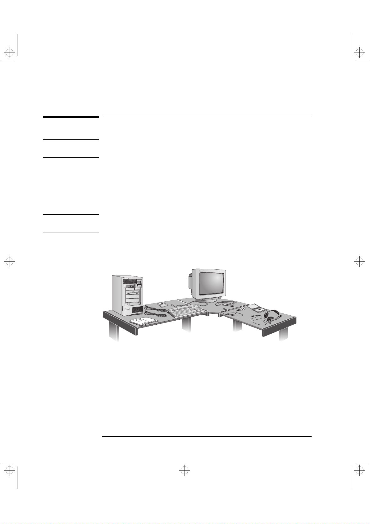
1 When you receive your PC Workstation, unpack all of the
components:
Computer and power cords
•
Display and its video cable
•
HP enhanced keyboard, mouse, and headphones
•
Manuals and driver kit.
•
NOTE Device drivers, HP utilities, and an online Network Administrator Guide
are preloaded on your system and provided in a driver kit.
Installation Tools
2 Place the PC Workstation on (or under) a sturdy desk with easily
accessible power outlets and enough space for the keyboard, mouse,
and any other accessories.
3 Position the PC Workstation so that its rear connectors are easily
accessible.
4 Place the display next to the computer.
No tools are required to install your PC Workstation. However, if you
plan to install a disk drive or an accessory board inside your
PC Workstation, you will need a flat-blade screwdriver. For more
information on installing accessories, refer to "How to Install
Accessories Inside Your PC Workstation", on page 23.
2 English
Page 19
crystal.bk : cryst-1.fb4 Page 3 Monday, March 23, 1998 4:09 AM
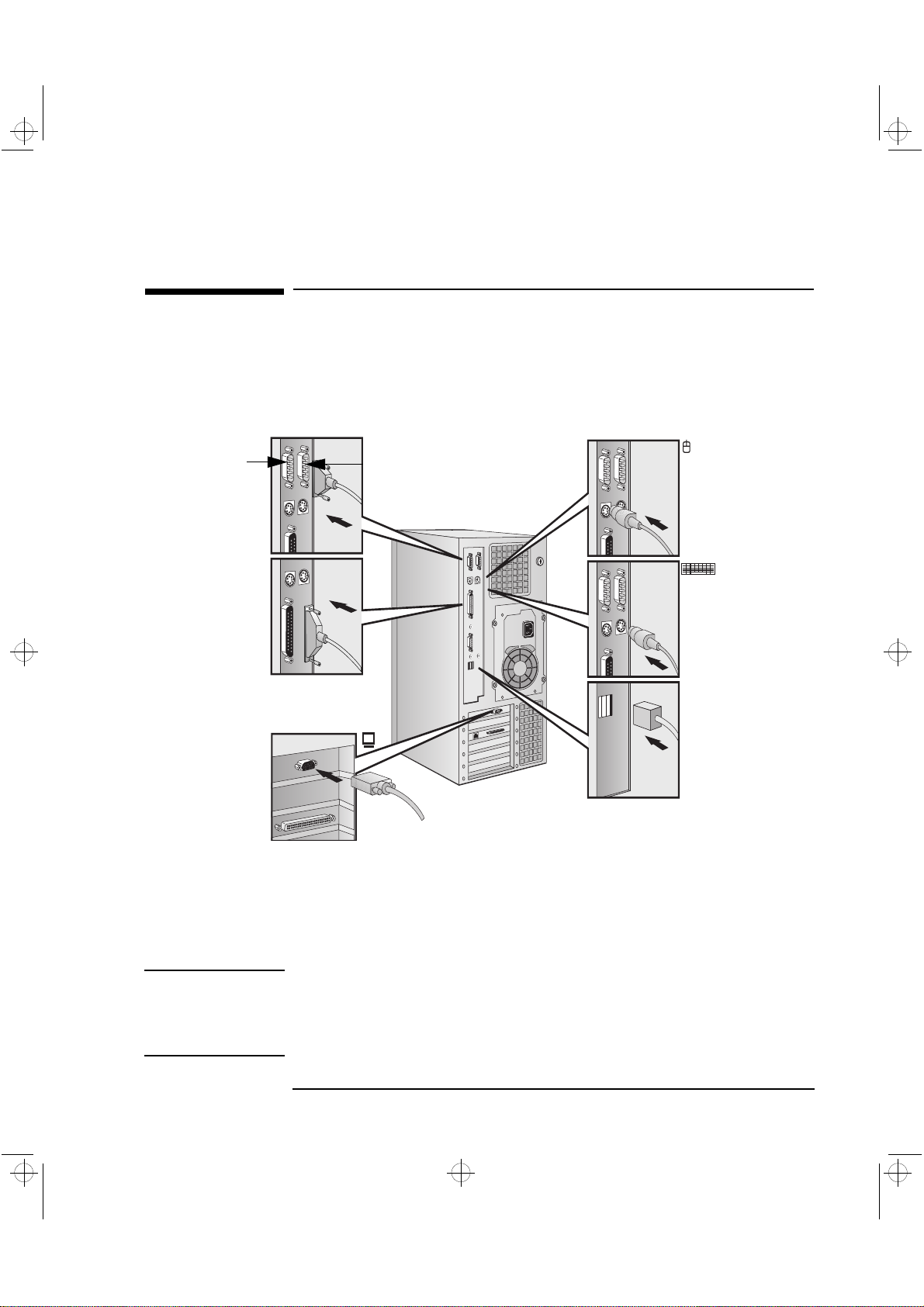
Connecting the Mouse, Keyboard, Display and Printer
Connect the mouse, keyboard, and display to the back of the
PC workstation. The connectors are shaped to go in one way only.
Tighten the display cable attachment screws.
1 Setting Up and Using Your PC Workstation
Connecting the Mouse, Keyboard, Display and Printer
Serial B
Port
Parallel
Connector
Monitor
Connector
Serial A
Port
Mouse
Connector
Keyboard
Connector
2 USB Connectors
(see note below)
Connect the printer cable to the back of the computer and tighten the
attachment screws. Use the connector labeled:
Parallel (25-pin parallel connector) for a parallel device.
•
Serial A (9-pin serial connector) for a serial device.
•
Serial B (9-pin serial connector) for a second serial device.
•
NOTE The Universal Serial Bus (USB) connectors can be used for USB
accessories. Most USB accessories are automatically configured as soon
as they are physically attached to the PC Workstation. USB accessories
are not supported by all operating systems.
English 3
Page 20
crystal.bk : cryst-1.fb4 Page 4 Monday, March 23, 1998 4:09 AM
1 Setting Up and Using Your PC Workstation
Connecting to a Network
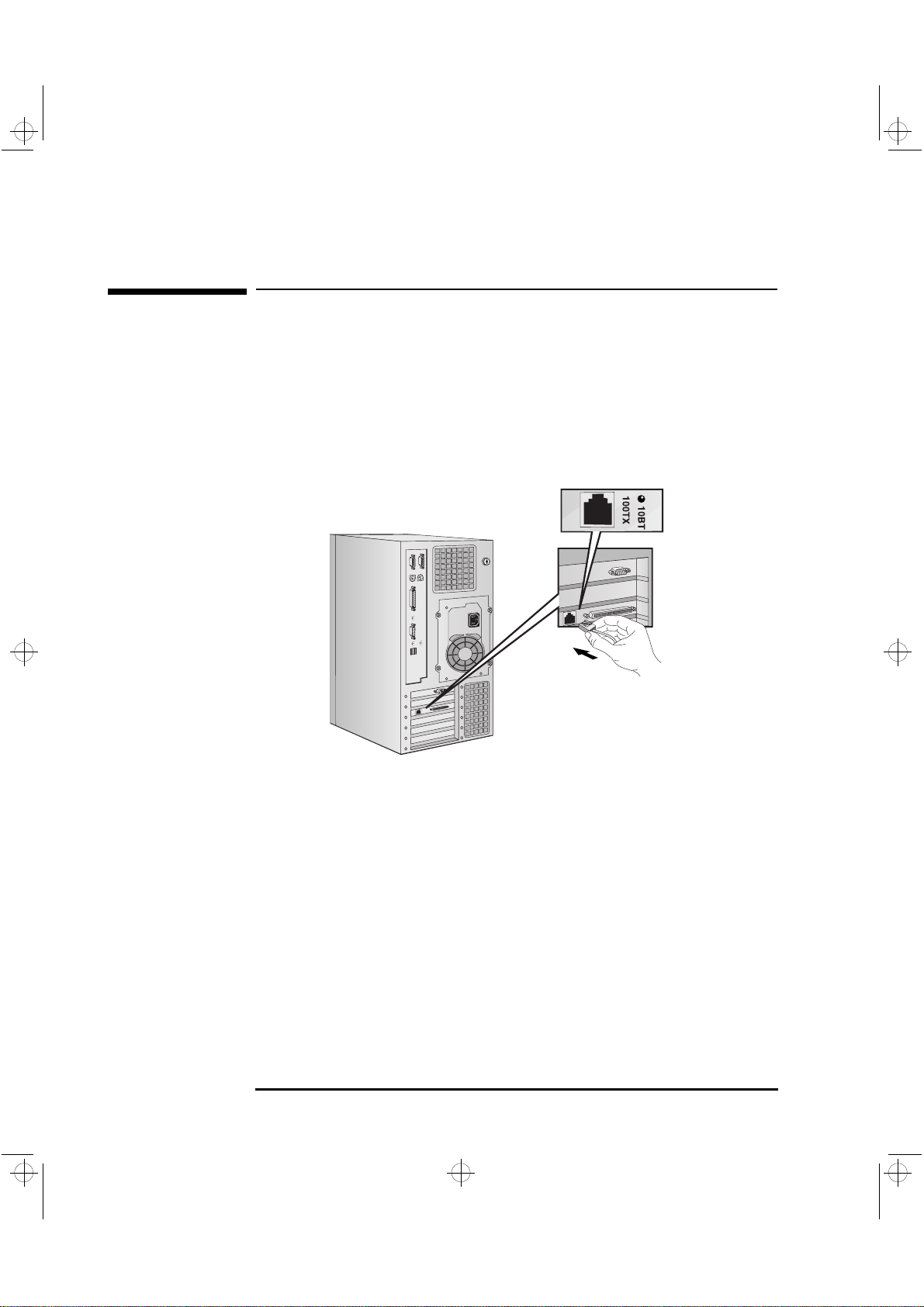
Connecting to a Network
Your PC Workstation has a 10BT/100TX LAN interface adapter.
The LAN adapter supports both 10 Mbit/s and 100 Mbit/s operations
and automatically detects which network type is being used.
1 Connect the RJ-45 plug on your network cable to the LAN connector
on the LAN Adapter. Push the plug into the connector until the plug
clicks into place.
The board shown here is
a combined SCSI/LAN
board.
2 Attach the other end of the LAN cable to a hub (or into a wall socket
that is connected to a hub).
Let your Network Administrator know that you are connecting your
PC Workstation to the network.
For further instructions on configuring your network connection,
refer to “Configuring Your Network Connection” on page 103.
Refer also to the online Network Administrator’s Guide
(preloaded onto your PC Workstation) for further instructions on
setting up your PC Workstation for a LAN connection.
4 English
Page 21
crystal.bk : cryst-1.fb4 Page 5 Monday, March 23, 1998 4:09 AM
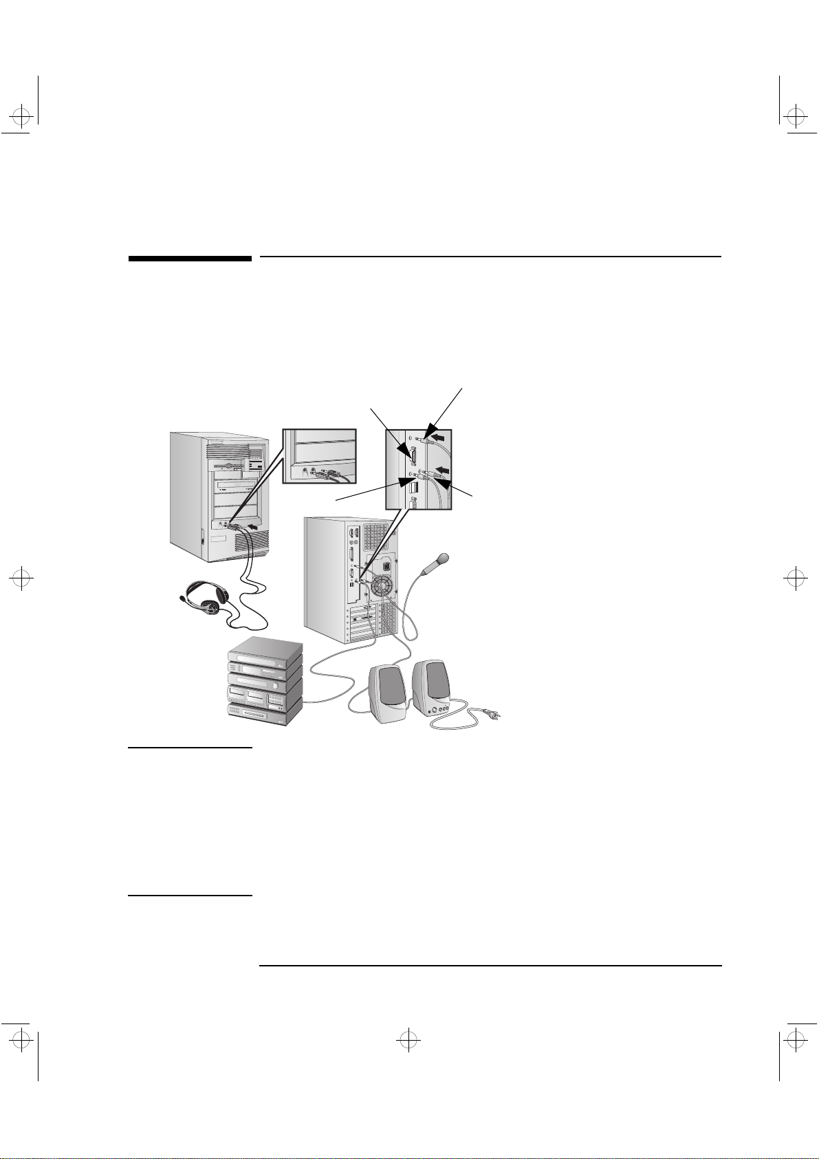
Connecting Audio Accessories
Your PC Workstation has a Headphone Out jack and a Microphone In
jack on the Audio Front Panel (see page 98 for more information). A
LINE IN jack, LINE OUT jack, MIC IN jack, and MIDI/Joystick
connector are located on the rear panel (see page 95 for details).
LINE OUT jack
Audio Front Panel
LINE IN jack
Dual MIDI/Joystick
connector
1 Setting Up and Using Your PC Workstation
Connecting Audio Accessories
NOTE
The internal speaker and LINE OUT
jack on the rear panel of your
MIC IN jack
PC Workstation are deactivated
when you use the Headphones jack
on the Audio Front Panel.
The internal speaker is deactivated
when you use the LINE OUT jack.
External speakers you connect
should have a built-in power
supply.
The audio accessories shown
here (microphone, speakers, and
audio system) are not supplied
with your PC Workstation.
Volume can be controlled through
the HP enhanced keyboard, or the
software volume control.
WARNING To avoid discomfort from unexpected noise, always turn down the
volume before connecting headphones or speakers.
Listening to loud sounds for prolonged periods may permanently
damage your hearing.
Before putting on headphones, place them around your neck and turn
down the volume. When you put on the headphones, slowly increase
the volume until you find a comfortable listening level, then leave the
volume control in that position.
English 5
Page 22
crystal.bk : cryst-1.fb4 Page 6 Monday, March 23, 1998 4:09 AM
1 Setting Up and Using Your PC Workstation
Connecting an External SCSI Accessory
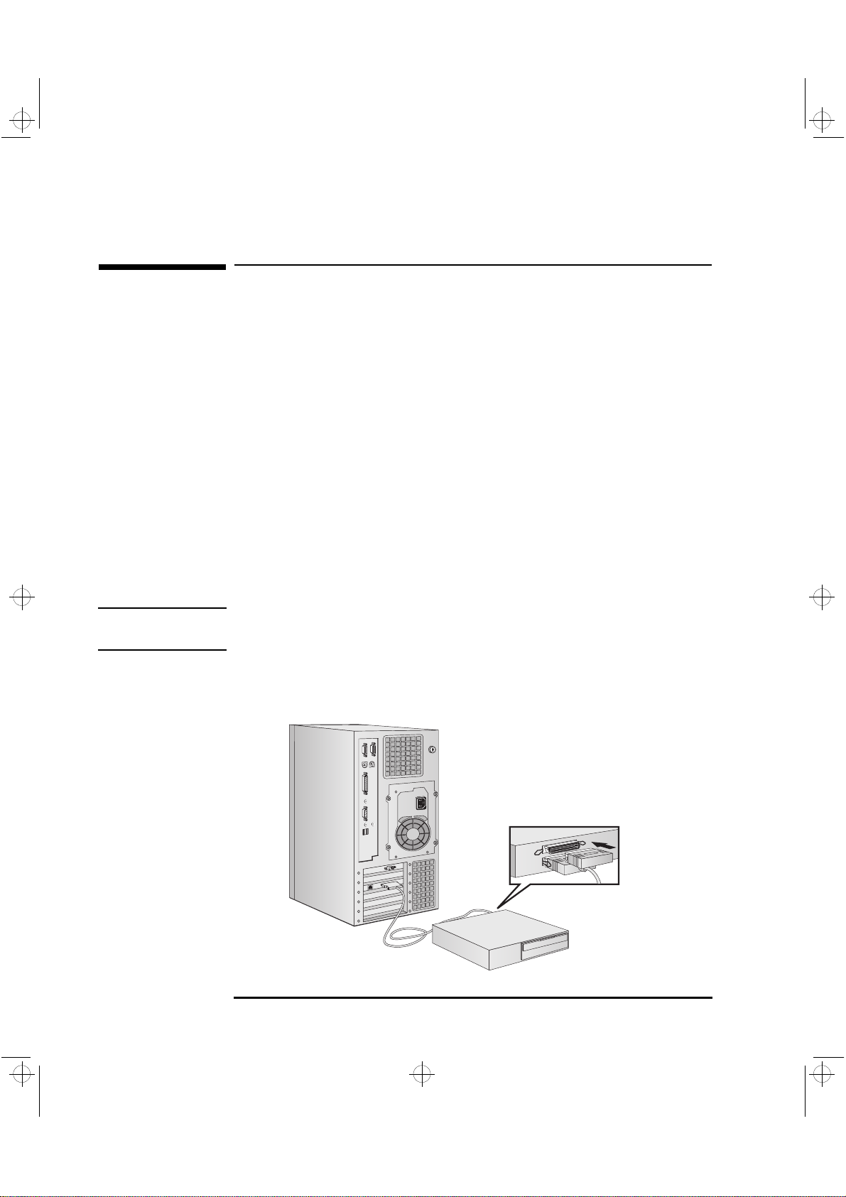
Connecting an External SCSI Accessory
Your PC Workstation is equipped with an UltraWide 16-bit SCSI
connector for external SCSI devices.
When an external SCSI device is connected, the UltraWide 16-bit SCSI
controller automatically switches to non-Ultra mode (maximum
capacity of 20 MBs per second).
An external SCSI device is connected as follows:
1 You should assign an unused SCSI address to the accessory. SCSI
addresses range from 0 to 15 for wide 16-bit SCSI. The SCSI
address 0 is reserved for the first SCSI hard disk drive and SCSI
address 7 is reserved for SCSI controller (the default for narrow and
wide SCSI devices).
Refer to the manual provided with the SCSI accessory for
instructions on selecting a SCSI address.
NOTE You don’t need to set a SCSI address for Plug and Play SCSI devices
(SCSI devices which support the SCAM protocol).
2 Make sure the SCSI accessory is terminated correctly—either
internally or by a terminating resistor (refer to the manual provided
with the SCSI accessory).
Make sure the SCSI
accessory is terminated
6 English
Page 23
crystal.bk : cryst-1.fb4 Page 7 Monday, March 23, 1998 4:09 AM
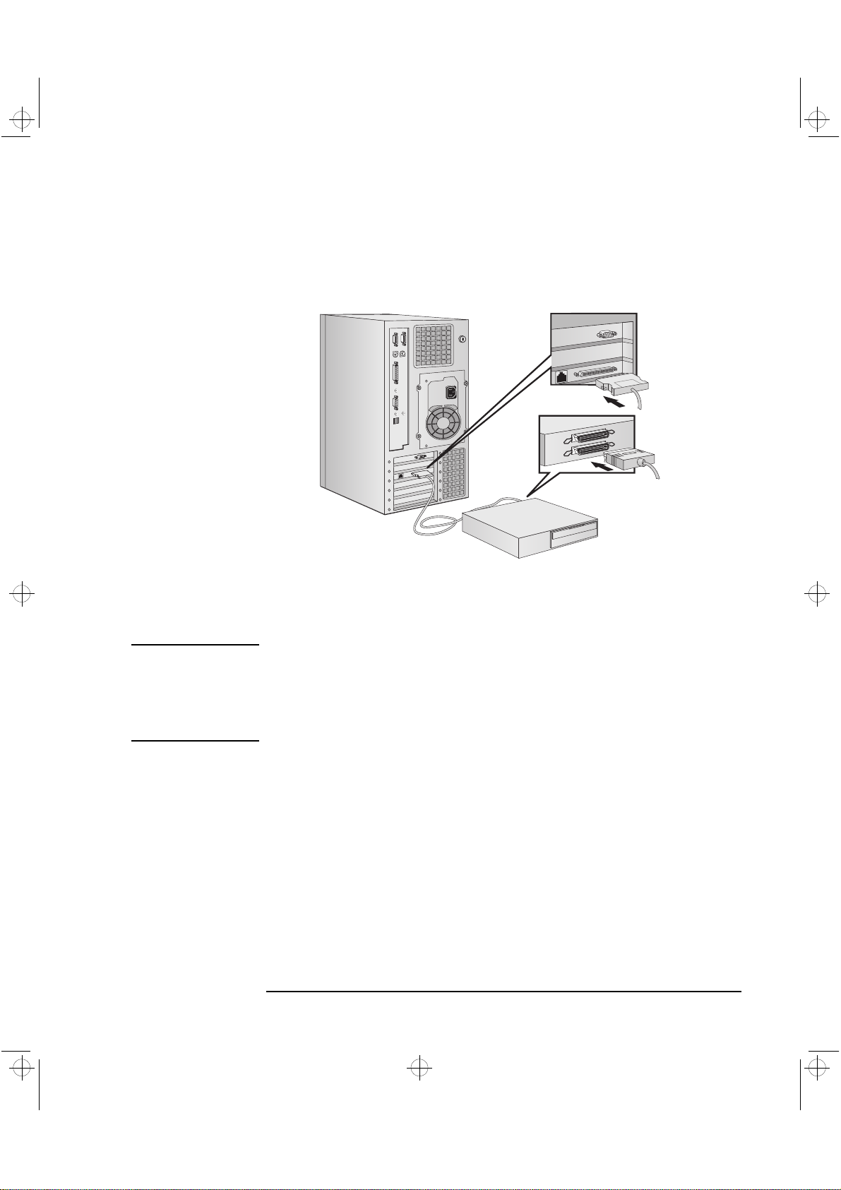
3 Connect the SCSI accessory to your PC Workstation’s external 16-bit
SCSI connector with a shielded SCSI cable.
1 Setting Up and Using Your PC Workstation
Connecting an External SCSI Accessory
4 Refer to the manual provided with the SCSI accessory to learn how
to install any software that may be necessary to use it.
NOTE The total length of the external SCSI cables should not exceed 3 meters
(approximately 10 feet).
Contact your dealer to order shielded HP SCSI cables to connect
external SCSI accessories.
See page 37 for information on how to connect internal SCSI devices.
English 7
Page 24
crystal.bk : cryst-1.fb4 Page 8 Monday, March 23, 1998 4:09 AM
1 Setting Up and Using Your PC Workstation
Connecting the Power Cords
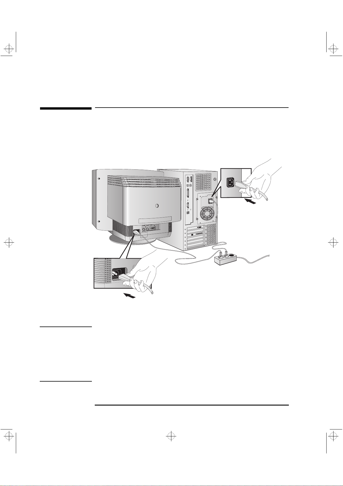
Connecting the Power Cords
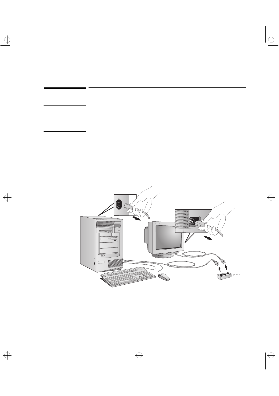
1 Remove any warning labels that may be covering the computer’s
power connector on the rear of the computer.
2 Connect the power cords to the display and the computer. (The
connectors are shaped to go in one way only.)
PC Workstation
Power Connector
Grounded Outlet
Monitor Power Connector
3 Connect the display’s power cord and the computer’s power cord to
grounded outlets.
WARNING For your safety, always connect the equipment to a grounded wall
outlet. Always use a power cord with a properly grounded plug, such
as the one provided with this equipment, or one in compliance with
your national regulations. This PC Workstation is disconnected from
the power by removing the power cord from the power outlet. This
means the PC Workstation must be located close to a power outlet that
is easily accessible.
8 English
Page 25
crystal.bk : cryst-1.fb4 Page 9 Monday, March 23, 1998 4:09 AM
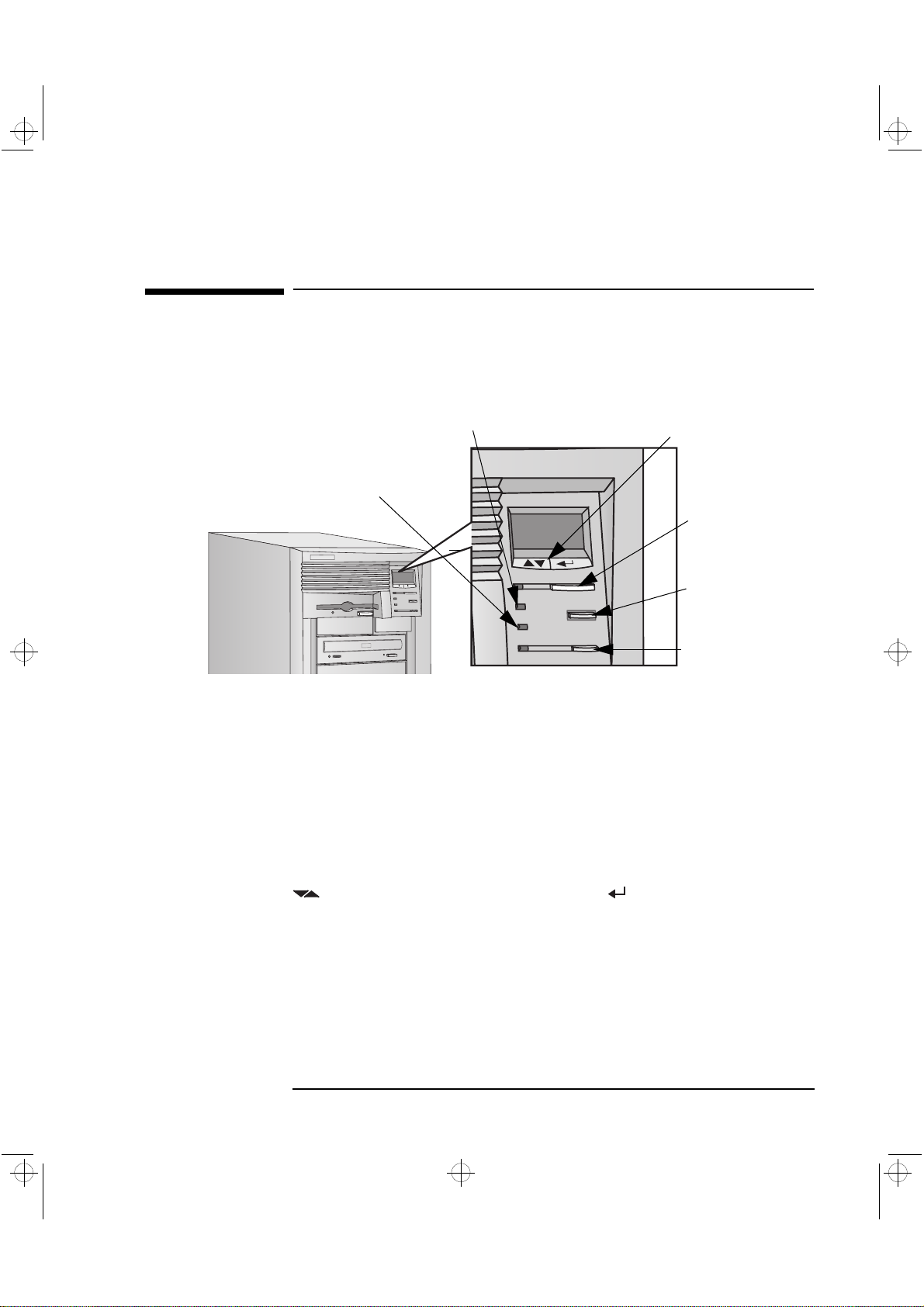
Your PC Workstation’s Hardware Control Panel
The hardware control panel is located on the front of your
PC Workstation.
1 Setting Up and Using Your PC Workstation
Your PC Workstation’s Hardware Control Panel
PC Lock Button
HP MaxiLife and it’s
Liquid Crystal Display
(LCD)
Hard Disk Activity Light
Network Activity Light
LCD Control Buttons
Power On/Off Button
and LED
Reset Button
PC Lock Button
and LED
With HP Lock installed, you can use this button to prevent
unauthorized access of your PC W orkstation during your absence. Your
applications will remain active. You unlock the PC Workstation by
entering a password (refer to “Setting Passwords” on page 18).
HP MaxiLife and it’s LCD helps you diagnose problems with your PC
Workstation and provides system information you may need to obtain
support. Press one of the LCD control buttons to display the menu. Use
to scroll through the menu items and to select the item
required. For more information on using the LCD, refer to “Using HP
MaxiLife to Diagnose Problems” on page 75.
Network Activity Light
Hard Disk Activity Light
This light glows/flickers when your PC Workstation is accessing
the network.
This light glows/flickers when your hard disk drive is being accessed.
English 9
Page 26
crystal.bk : cryst-1.fb4 Page 10 Monday, March 23, 1998 4:09 AM
1 Setting Up and Using Your PC Workstation
Starting and Stopping Your PC Workstation
Starting and Stopping Your PC Workstation
Starting Your PC Workstation for the First Time
If your PC Workstation has preinstalled software, it is initialized the
first time you start the PC Workstation. The software initialization
process takes a few minutes. This process sets up the software in your
language and sets up your software to use the hardware installed in
your computer (you can change the settings after the software has
been initialized).
Initializing Your Software
NOTE Do NOT switch OFF the PC Workstation while the software is being
initialized—this could cause unexpected results.
To initialize your software:
1 Turn on the display first, and then the PC Workstation.
When the PC Workstation is switched on, the HP PC Workstation’s
logo is displayed. The PC Workstation performs a Power-On-SelfTest (POST). Press if you want to view the POST details in the
HP Summary Screen (refer to “The HP Summary Screen and Setup
Program” on page 101).
If an error is detected during the Power-On-Self-Test, the
PC Workstation will automatically display the error. You may be
prompted to press to start the Setup program to correct the
error.
2 The software initialization routine starts. It displays the software
license agreement, gives you an opportunity to read Working in
Comfort (ergonomic advice for computer users), and then asks
questions about the PC Workstation. For example:
The name of the person who will use the PC Workstation and your
•
company name. (If necessary, the name of the user can be
modified later.)
10 English
Page 27

crystal.bk : cryst-1.fb4 Page 11 Monday, March 23, 1998 4:09 AM
The current date and time.
•
The type of printer (for example, HP LaserJet 5L). This is shown
•
on the front of the printer. You also need to enter the connection
used by the printer.
3 While the initialization program is running, you can complete the
Warranty Registration card that came with this manual.
4 When the initialization routine has finished, click OK and the
PC Workstation will restart.
Creating Back-up Diskettes
It is very important that you create master diskettes for your preloaded
application software and as an Emergency Repair Disk for the
operating system, as soon as possible. HP recommends that you use
new diskettes for this purpose. To create these back-up diskettes,
follow the instructions that appear on screen when you first start your
PC Workstation.
1 Setting Up and Using Your PC Workstation
Starting and Stopping Your PC Workstation
For more information on how to create these diskettes, refer to the
documentation that came with your application software or operating
system.
Starting Your PC Workstation
1 Before you start your PC Workstation, first switch on the display.
2 Start your PC Workstation in one of these ways:
Press the power button on the front panel.
•
Press the keyboard space bar.
•
The keyboard power-on feature will work only if Space-bar is
enabled in the Power menu of the Setup program (refer to page
101) and the sy stem board switch 8 (KEYB power) is DOWN (the
default setting). Refer to page 99 for more information on sy stem
board switches.
English 11
Page 28
crystal.bk : cryst-1.fb4 Page 12 Monday, March 23, 1998 4:09 AM
1 Setting Up and Using Your PC Workstation
Starting and Stopping Your PC Workstation
When you switch on the computer, it carries out the Power-On-SelfTest (POST) while the PC Workstation’s logo is displayed. If you
wish to view the POST details, press to get the HP Summary
Screen. If there is an error in the POST, the error will automatically
be displayed. For details, refer to “If a POST Error Message is
Displayed” on page 61.
3 If you have set a password in the PC Workstation’s Setup program,
the password prompt displays after the POST has completed. If the
Password prompt is displayed, type your password and press
to be able to use the PC Workstation.
Stopping Your PC Workstation
To stop the PC Workstation, make sure that you have exited all
programs and the operating system (if necessary), and then press the
power button on the control panel.
12 English
Page 29
crystal.bk : cryst-1.fb4 Page 13 Monday, March 23, 1998 4:09 AM
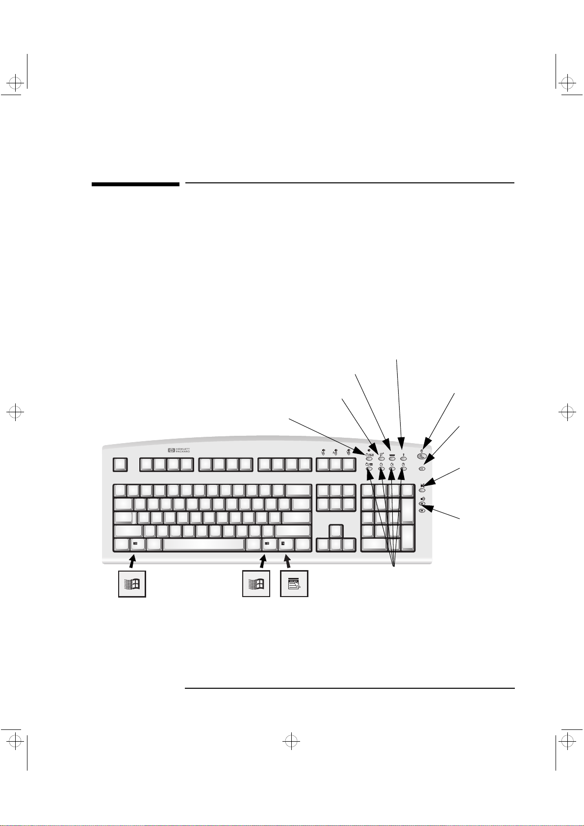
Using Your HP Enhanced Keyboard
The HP enhanced keyboard includes soft keys you can use to:
Display and configure the actions assigned to keys.
•
Perform one-touch shortcuts to start applications, open files, or
•
open sites on the WWW.
Launch the Internet browser supplied with your system.
•
Lock or suspend your PC Workstation.
•
Access HP TopTools and customer information.
•
Mute or adjust the volume of the audio system.
•
Internet key
1 Setting Up and Using Your PC Workstation
Using Your HP Enhanced Keyboard
Menu key
Shortcut key
HP TopTools
Lock/Suspend key
HP Customer
Information
Mute key
Volume
control
keys
Shortcut keys
English 13
Page 30

crystal.bk : cryst-1.fb4 Page 14 Monday, March 23, 1998 4:09 AM
1 Setting Up and Using Your PC Workstation
Using Your HP Enhanced Keyboard
Menu Key
Shortcut Keys
Internet Key
Lock/Suspend Key
Pressing the Menu soft key displays the soft key section of the HP
enhanced keyboard on your screen. Click any of the key s on the screen
to display the action assigned to an individual key or to change or
assign an action to a key. Shortcut keys are provided specifically for
user-defined actions.
The Shortcut soft keys can be used to start an application, open a
document, or open a site on the Internet. Actions can be assigned to
the Shortcut keys by pressing the Menu key and clicking the key you
want to configure in the keyboard displayed on your screen.
This soft key is used to start the Netscape™ Communicator 4.0
browser configured on the PC Workstation (default setting). The
Microsoft
Internet Explorer is also available.
®
The action of the Lock/Suspend key is configured by pressing the Menu
Key , and then clicking on
onscreen
Lock
button. With HP Lock installed, the actions you can
Configure, the Extended Keys tab and the
specify for the Lock/Suspend key are:
Launch screen saver
•
Lock the front panel
•
HP TopTools
Pressing this soft key opens HP TopTools. This application helps you
manage and reduce overall ownership costs and provides advanced
PC management tools that can, for example, be used for remote BIOS
updates and security management.
NOTE Before using HP TopTools for the first time, you must install it
as follows: From the Start menu, select Programs, then
HP DMI, then Setup. The HP TopTools application is installed
automatically.
14 English
Page 31

crystal.bk : cryst-1.fb4 Page 15 Monday, March 23, 1998 4:09 AM
The System Health window of the HP TopTools hardware monitoring
facility provides information on:
Fan Control in the HP UltraFlow cooling system
•
System Temperature for PC Workstation components
•
ECC Error Notification (only when ECC DIMMs are installed)
•
Voltage Monitoring for components
•
1 Setting Up and Using Your PC Workstation
Using Your HP Enhanced Keyboard
HP Customer
Information
Mute and Volume Keys
This soft key accesses HP Customer Information, which includes:
Information on product features
•
The preloaded software on the system
•
Details on how to configure the HP enhanced keyboard
•
Information on how to configure the WWW browser
•
Detailed HP support information
•
Links to the HP PC and PC Workstation website
•
Pressing the Mute key mutes the audio, or restores the audio if it has
been muted. The Volume keys can be used to control the volume level.
For more information on controlling audio on your system, see the
Using Sound guide preloaded onto your PC Workstation.
English 15
Page 32
crystal.bk : cryst-1.fb4 Page 16 Monday, March 23, 1998 4:09 AM
1 Setting Up and Using Your PC Workstation
Using Your HP Enhanced Mouse
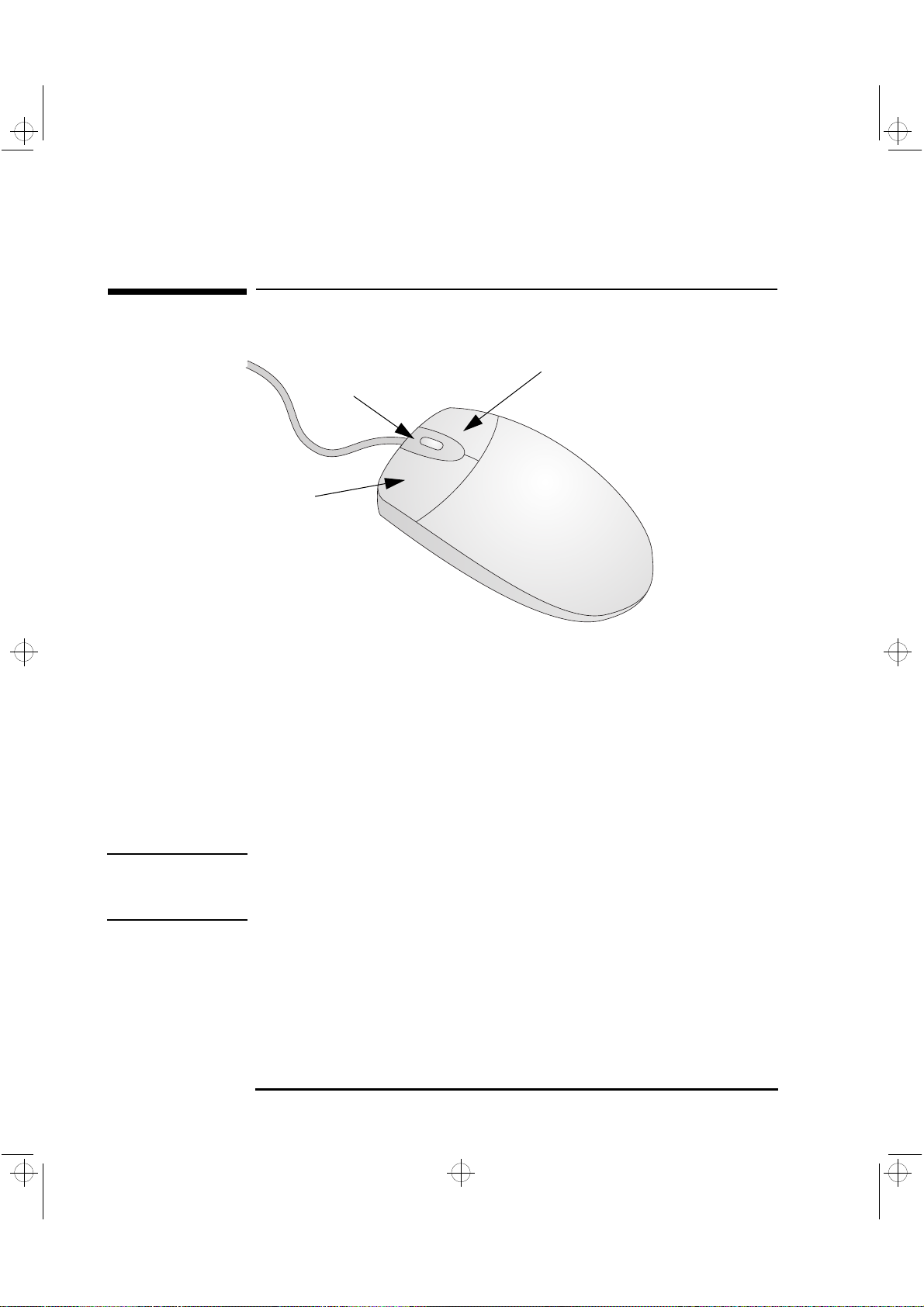
Using Your HP Enhanced Mouse
Context Menu/Alternate
Select Button
Scroll/Zoom Wheel
Click/Select Button
XU Models
XU Models
Your HP enhanced mouse includes the following additional features:
A combination mouse wheel/button that enables you either to scroll
•
down by pushing the mouse wheel forwards and scroll up by pushing
it backwards.
A mouse wheel that enables you to zoom in (enlarge) by holding the
•
Ctrl
key down and pushing the mouse wheel forwards, or zoom out
(reduce) by holding the
Ctrl key down and pushing it backwards.
NOTE The scroll functions only work in Windows NT and Windows 95
applications that support scrolling. The zoom function works only in
Microsoft Office 97 compatible applications that support zoom.
Using the mouse setup, you can assign each mouse button and the
mouse wheel to a different function. Also, you can change the scroll
function to work in a different way.
To do this or to see the available scroll options, click the
select
Settings—Control Panel
Buttons tab.
, double-click
Mouse
Start button,
, and select the
16 English
Page 33
crystal.bk : cryst-1.fb4 Page 17 Monday, March 23, 1998 4:09 AM
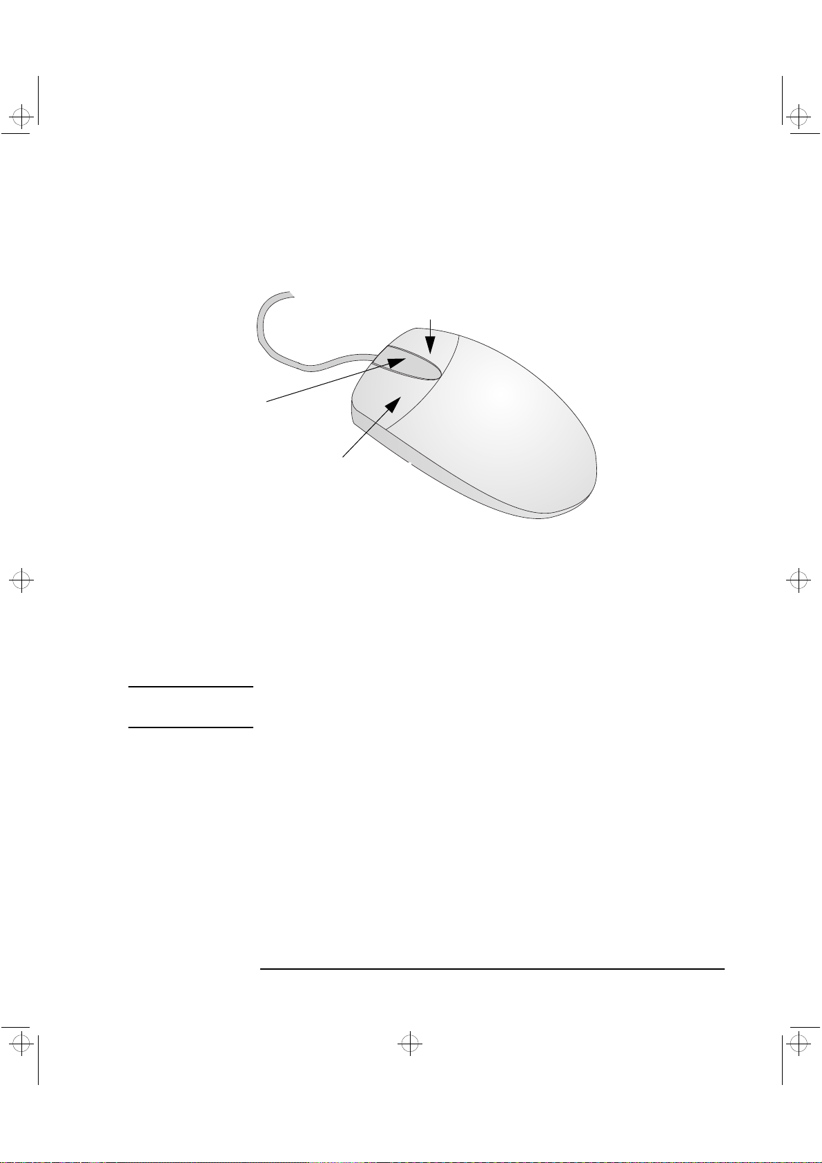
Context Menu/Alternate
Select Button
Additional Control Button
for 3D CAD/CAM
Applications
Click/Select Button
1 Setting Up and Using Your PC Workstation
Using Your HP Enhanced Mouse
XW Models
XW Models
Your HP enhanced mouse includes the following additional features:
A third control button — useful when using certain 3D CAD, CAM
•
and other graphics-intensive Windows NT applications.
Control buttons can be customized, using mouse setup, to perform
•
different control functions according to user requirements.
NOTE The third button control will only work in Windows NT and W indows 95
applications that support a third control button.
English 17
Page 34
crystal.bk : cryst-1.fb4 Page 18 Monday, March 23, 1998 4:09 AM
1 Setting Up and Using Your PC Workstation
Setting Passwords
Setting Passwords
You can set two passwords, the Administrator (or Supervisor)
password and the User password, to provide two levels of protection
for your PC Workstation. You set both passwords using the Security
menu in the Setup program ( refer to “The HP Summary Screen and
Setup Program” on page 101).
Setting an Administrator Password
Set the Administrator password to protect the PC Workstation’s
configuration in Setup. An Administrator password can provide a
power-on password prompt that prevents your PC Workstation from
being started or used in your absence. You can also use this password
to start the PC Workstation when the keyboard and mouse are
locked—you must type the password and press to unlock the
keyboard.
If you have set both an Administrator password and a User password,
and you enter the Setup program using the User password, you will be
restricted in your ability to change setup items. If you enter the Setup
program with an Administrator password, you will have no restrictions.
To set an Administrator password:
1 Start the Setup program ( refer to “The HP Summary Screen and
Setup Program” on page 101).
2 Select the Security menu.
3 Select the Administrator password submenu.
4 Choose the Set Administrator password setup item. You will be
asked to enter your password twice. Save your changes when you
exit the Setup program by selecting Exit, then Exit Saving Changes.
To remove the password, follow the same procedure as to set a
password. You will be asked to enter the existing password first. Then,
for the new password, leave the password field blank and press
. To confirm your choice, press a second time.
18 English
Page 35
crystal.bk : cryst-1.fb4 Page 19 Monday, March 23, 1998 4:09 AM
NOTE If you forget your password, refer to “If You Have Forgotten Your
Password” on page 72.
Setting a User Password
A User password can only be set if an Administrator password has
already been set.
Set a User password to:
Provide a power-on password prompt to prevent your
•
PC Workstation being started or used in your absence.
Start the PC Workstation when the keyboard and mouse are
•
locked—you must type the password and press to unlock
the keyboard ( refer to “The HP Summary Screen and Setup
Program” on page 101).
1 Setting Up and Using Your PC Workstation
Setting Passwords
If you have set both an Administrator password and a User password,
and you enter the Setup program using the User password, you will be
restricted in your ability to change setup items. If you enter the Setup
program with an Administrator password, you will have no restrictions.
To set a User password:
1 Start the Setup Program.
2 Select the Security menu.
3 Select the User Password submenu.
4 Choose the Set User Password setup item. You will be asked to enter
your password twice. Save your changes when you exit the Setup
program by selecting Exit, then Exit Saving Changes.
To remove the password, follow the same procedure as to set a
password. You will be asked to enter the existing password first. Then,
for the new password, leave the password field blank and press
. To confirm your choice, press a second time.
NOTE If you forget your password, refer to “If You Have Forgotten Your
Password” on page 72.
English 19
Page 36

crystal.bk : cryst-1.fb4 Page 20 Monday, March 23, 1998 4:09 AM
1 Setting Up and Using Your PC Workstation
Using Power Management
Using Power Management
Power management enables you to reduce your PC Workstation’s
overall power consumption by slowing down the PC Workstation’s
activity when it is idle. To configure power management, refer to the
Power menu in the Setup program. ( refer to “The HP Summary
Screen and Setup Program” on page 101, for more information).
Refer to your operating system documentation for detailed information
about the capability of your operating system to implement power
management.
Additional Information and Help
Additional information about your PC W orkstation is preloaded on your
PC Workstation’s hard disk drive. This information includes:
New features—what is new and special about your PC Workstation
•
Working in comfort—guidance on ergonomic issues
•
Using Sound—provides guidance on audio issues
•
Network Administrators Guide — provides instructions on setting up
•
your PC Workstation for a LAN connection.
Glossary
•
Users of Windows 95 and Windows NT 4.0 can access this information
by opening the Start menu in the task bar and selecting Programs>
HPInfo.
20 English
Page 37

crystal.bk : cryst-1.fb4 Page 21 Monday, March 23, 1998 4:09 AM
Recycling an Old HP PC Workstation
HP has a strong commitment towards the environment. This HP
PC W orkstation has been designed to respect the environment as much
as possible.
HP can take an old computer back for recycling when it reaches the
end of its useful life.
In several countries, HP has a product take-back program. Collected
equipment is sent to one of HP’s recycling facilities in Europe or the
USA. As many parts as possible are reused, the remainder are recycled.
Special care is taken with batteries and other potentially toxic
substances, which are reduced to non-harmful components through a
special chemical process.
1 Setting Up and Using Your PC Workstation
Recycling an Old HP PC Workstation
If you require more details about HP’s product take-back program,
contact your dealer or your nearest HP Sales Office.
English 21
Page 38

crystal.bk : cryst-1.fb4 Page 22 Monday, March 23, 1998 4:09 AM
1 Setting Up and Using Your PC Workstation
Recycling an Old HP PC Workstation
22 English
Page 39

crystal.bk : cryst-2.fb4 Page 23 Monday, March 23, 1998 4:09 AM
2
How to Install Accessories
Inside Your PC Workstation
This chapter explains how to install accessories, such as extra memory ,
accessory boards, and additional disk drives, in your PC Workstation.
Page 40

crystal.bk : cryst-2.fb4 Page 24 Monday, March 23, 1998 4:09 AM
2 How to Install Accessories Inside Your PC Workstation
Supported HP Accessories
Supported HP Accessories
This chapter describes how to install memory, mass storage devices,
and accessory boards in your computer.
Internal Mass
Storage Devices
5 Pairs of Rails for Front
Access Devices:
- 3.5-inch disk drive rails
- 5.25-inch disk drive rails
Up to six accessory boards
can be installed:
- One AGP slot (graphics)
- Three 32-bit PCI slots (one used by SCSI/LAN board, one with RAID
- One combination PCI or ISA slot
- One 16-bit ISA slot
Contact your dealer for an up-to-date list of supported devices.
port
Main Memory Upgrades
(DIMM slots for ECC SDRAM):
- 32 MB (Non-buffered)
- 64 MB (Non-buffered)
- 128 MB (Non-buffered)
- 256 MB (Registered - see note below)
Front Access Drives, for example:
- 3.5-inch 1.44 MB flexible disk drive
(one third height)
- 5.25-inch 1.2 MB flexible disk drive
(half height)
- 5.25-inch tape drive (half height)
)
NOTE 256 MB registered ECC SDRAM DIMMs cannot be used with non-
buffered 32 MB, 64 MB or 128 MB DIMMs.
24 English
Page 41
crystal.bk : cryst-2.fb4 Page 25 Monday, March 23, 1998 4:09 AM
2 How to Install Accessories Inside Your PC Workstation
Removing and Replacing the Cover
WARNING For your safety, never remove the PC Workstation’s cover without first
removing the power cord from the power outlet, and any connection to
a telecommunications network. Always replace the cover on the
PC Workstation before switching it on again.
Removing the Cover
1 Switch off the display and computer.
2 Disconnect all power cables and any telecommunications cables.
Removing and Replacing the Cover
3 If necessary, unlock the cover using the key on the back panel.
English 25
Page 42

crystal.bk : cryst-2.fb4 Page 26 Monday, March 23, 1998 4:09 AM
2 How to Install Accessories Inside Your PC Workstation
Removing and Replacing the Cover
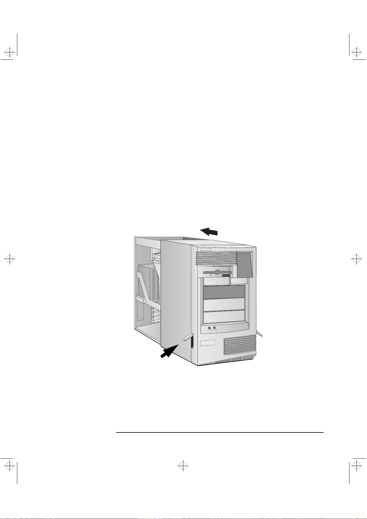
4 Lift the two latches on the front sides of the computer upwards.
5 Grasp the cover on the sides at the back of the computer and slide it
forwards and off the computer.
26 English
Page 43
crystal.bk : cryst-2.fb4 Page 27 Monday, March 23, 1998 4:09 AM
2 How to Install Accessories Inside Your PC Workstation
Replacing the Cover
1 Ensure that you have installed all your accessories and that all
internal cables are properly connected and safely routed.
2 Ensure that the two latches on the front sides of the cover are lifted
up, and that the lock is unlocked.
3 Slide the cover onto the computer, making sure that the two guides
at the bottom of the case slide into the two rails at the base of the
computer. Firmly slide the cover backwards into position.
Removing and Replacing the Cover
Press here on both sides
of the PC’s cover.
English 27
Page 44

crystal.bk : cryst-2.fb4 Page 28 Monday, March 23, 1998 4:09 AM
2 How to Install Accessories Inside Your PC Workstation
Removing and Replacing the Cover
4 Lower the latches on the front sides of the cover.
Intrusion Monitor
5 If required, lock the cover using the key provided.
6 Reconnect all the power cables.
Your PC Workstation is equipped with an intrusion monitor, which is
located on the front of the PC Workstation, behind the Hardware
Control Panel. It is designed to detect whether your PC Workstation
has been opened since the last time it was used:
If your PC Workstation has been opened, it is assumed that the
•
sy stem configuration has changed and a full start-up check is carried
out.
If your PC Workstation has not been opened, it is assumed that the
•
system configuration has not changed and a reduced start-up check
is carried out.
28 English
Page 45

crystal.bk : cryst-2.fb4 Page 29 Monday, March 23, 1998 4:09 AM
2 How to Install Accessories Inside Your PC Workstation
Moving the Power Supply
You can slide the power supply unit out of the computer to improve
access to the sy stem board and the cables at the rear of the disk drives.
1 Disconnect the computer’s power cord and any telecommunications
cable.
2 Remove the computer’s cover (see page 25).
3 Press the retaining buttons on each side of the HP UltraFlow airflow
guide and lift it partly out of the PC Workstation’s case.
Fan connection to
system board
Moving the Power Supply
HP UltraFlow
Airflow Guide
Retaining button
Unscrew the
self-retaining screws
4 Remove the fan connection to the system board and lift the airflow
guide completely out of PC Workstation’s case.
5 Unscrew the four self-retaining screws at the back of the power
supply.
English 29
Page 46

crystal.bk : cryst-2.fb4 Page 30 Monday, March 23, 1998 4:09 AM
2 How to Install Accessories Inside Your PC Workstation
Moving the Power Supply
WARNING To avoid electrical shock, do not open the power supply.
6 Slide the power supply out of the computer until it stops—the power
supply unit remains connected to the computer.
Slide the power
supply unit clear of
the computer
Power Supply
Replacing the Power
Supply after Installing
Accessories
1 Check that all internal cables are safely routed.
2 Slide the power supply back into the computer.
3 Tighten the four self-retaining screws.
4 Replace the HP UltraFlow airflow guide.
5 Reconnect the fan to the system board.
30 English
Page 47

crystal.bk : cryst-2.fb4 Page 31 Monday, March 23, 1998 4:09 AM
2 How to Install Accessories Inside Your PC Workstation
Installing Memory
Main Memory Modules
If you need more main memory to run your application software, you
can install up to 1GB of memory in four DIMM slots.
Main memory upgrades are available in single 32 MB, 64 MB and
128 MB Non-Buffered ECC SDRAM or 256 MB Registered ECC SDRAM
memory modules. You should note that Registered ECC SDRAM
cannot be used with Non-Buffered memory modules. Do not attempt to
combine these two types of memory.
CAUTION Static electricity can damage electronic components. Turn off
all equipment. Do not let your clothes touch the accessory.
To equalize the static electricity, rest the accessory bag on top
of the power supply while you are removing the accessory from
the bag. Handle the accessory as little as possible and with care.
Installing Memory
To install a main memory module:
1 Disconnect the computer’s power cord and any LAN or
2 Remove the computer’s cover (see page 25).
3 Press the retaining buttons on each side of the HP UltraFlow airflow
Fan connection to
system board
HP UltraFlow
Airflow Guide
Retaining button
telecommunications cable.
guide and lift it partly out of the PC Workstation’s case.
English 31
Page 48

crystal.bk : cryst-2.fb4 Page 32 Monday, March 23, 1998 4:09 AM
2 How to Install Accessories Inside Your PC Workstation
Installing Memory
4 Remove the fan connection to the system board and lift the airflow
guide completely out of PC Workstation’s case.
5 Remove the Ultra wide 16-bit SCSI cable from the system board.
6 Remove the power supply and the transparent airflow guide covering
the processor sockets (if needed).
7 Remove the floppy disk drive data cable from the system board.
8 The location of the memory module slots is shown here.
32 English
Page 49

crystal.bk : cryst-2.fb4 Page 33 Monday, March 23, 1998 4:09 AM
2 How to Install Accessories Inside Your PC Workstation
9 Slide the memory module into the slot at 90° to the system board
(with the cutouts furthest away from the processor).
Installing Memory
Slide the memory module into the
slot at 90
Push the module until the
retaining clips click into position
o
to the system board
10 Firmly press the memory module completely into the connector
until the retaining clips click into position.
11 Repeat this procedure for each additional memory module you want
to install.
12 Install any other accessories if necessary, then replace all units and
reconnect all cables and power cords. Replace the cover (see page
27).
Memory module
cutouts
13 Check the HP Summary Screen to verify the new configuration
(refer to “The HP Summary Screen and Setup Program” on page
101).
English 33
Page 50
crystal.bk : cryst-2.fb4 Page 34 Monday, March 23, 1998 4:09 AM
2 How to Install Accessories Inside Your PC Workstation
Installing Memory
Installing More Memory on the Video Adapter
For XU Models
Your PC Workstation is equipped with a video adapter that supports 2D
and 3D graphics. If you need to have more video memory to display
more colors, higher resolutions, or for increased speed, you can install
more video memory on the video adapter.
To find out about available video memory upgrades, refer to the HP
World Wide Web Site at http://www.hp.com/go/kayaksupport/
Refer to page 90 for information on video resolutions.
CAUTION Static electricity can damage electronic components. Turn off
all equipment. Do not let your clothes touch the accessory.
Handle the accessory as little as possible and with care.
To install a video memory module:
1 Switch off the display and computer, and disconnect the power
supply cables and any telecommunications cables. Remove the
computer’s cover (see page 25) and carefully place the
PC Workstation on its side.
2 Carefully remove the board from the accessory slot, holding the
board at each end by its top edge. Do not bend the board. With its
components facing up, place the board on a clean, flat, solid, staticfree surface. Handle the board by its edges.
(The different accessory
slots are identified in the
illustration on page 96.)
3 Attach the memory module to the connectors on the video adapter.
34 English
Page 51

crystal.bk : cryst-2.fb4 Page 35 Monday, March 23, 1998 4:09 AM
2 How to Install Accessories Inside Your PC Workstation
4 Replace the video adapter in the computer. Carefully slide the board
back into its accessory slot. Firmly press the board into the socket.
Make sure that the board slides into the socket completely and does
not touch components on other boards. Secure the video adapter.
5 Install any other accessories before replacing the cover (see
page 27). Reconnect all cables and power cords.
Installing Memory
Completing the Video
Memory Installation
Procedure
NOTE If you need to use a special video driver for your application, you may
Video Adapter
Accessories Available
from Other Sources
For XW Models with
HP Visualize FX4
1 Switch on the PC Workstation.
2 Check the HP Summary Screen to verify the new configuration
(refer to "The HP Summary Screen and Setup Program", on page
101).
be asked to insert the CD-ROM or diskette containing the driver.
Additional accessories, including memory upgrades and a video
MPEG module, are available for your video adapter. However, these
accessories cannot be ordered from HP. Contact your dealer for more
details about these accessories.
To add a texture module to the HP Visualize FX4, refer to the Texture
Module Accessory User’s Guide shipped with this accessory.
English 35
Page 52

crystal.bk : cryst-2.fb4 Page 36 Monday, March 23, 1998 4:09 AM
2 How to Install Accessories Inside Your PC Workstation
Installing Mass Storage Devices
Installing Mass Storage Devices
If you need extra mass storage space for your application software, you
can install additional mass storage devices.
The computer has two internal shelves (for hard disk drives) and five
front-access drive shelves (for front-access drives and hard disk
drives).
Your computer is supplied with one 3.5-inch flexible disk drive and a
CD-ROM drive. If your computer is supplied with a hard disk, the hard
disk will be installed in the second internal shelf
Two internal shelves
for 3.5-inch disks
Two shelves for 3.5-inch
drives
Three shelves for 5.25-inch
drives
36 English
Page 53

crystal.bk : cryst-2.fb4 Page 37 Monday, March 23, 1998 4:09 AM
2 How to Install Accessories Inside Your PC Workstation
Connecting Devices
If you add an IDE Zip drive, hard disk drive, CD-ROM drive, CD-RW
drive, or tape drive, you need to connect it to power and data cables.
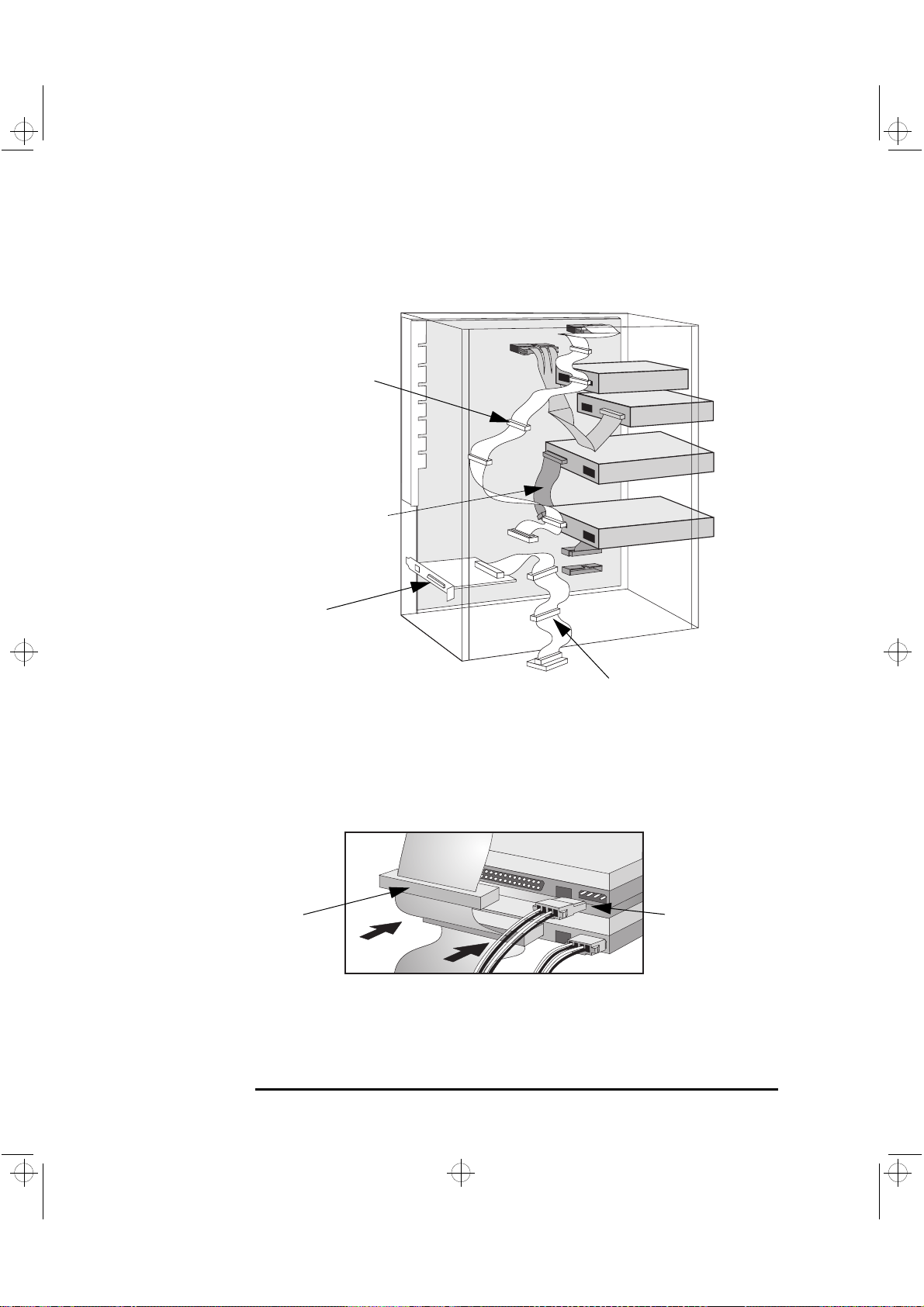
The data cables and connectors provided are shown below:
16-bit SCSI with five 68-pin SCSI connectors
Installing Mass Storage Devices
Cable with one connector for
3.5-inch Flexible Disk Drive
16-bit External 68pin SCSI connector
34-pin connector
68-pin SCSI connectors
Cable with two 40-pin connectors for
IDE Drives, such as CD-ROM Drives,
Zip Drives or Hard Disk Drives.
8-bit SCSI with two
50-pin SCSI connectors
English 37
Page 54

crystal.bk : cryst-2.fb4 Page 38 Monday, March 23, 1998 4:09 AM
2 How to Install Accessories Inside Your PC Workstation
Installing Mass Storage Devices
Which Data Connectors
to Use
Which Power
Connectors to Use
Your PC W orkstation has the following cables and connectors which may
be used by mass storage devices:
A cable for UltraWide 16-bit SCSI with five connectors.
•
A cable for UltraNarrow 8-bit SCSI with two connectors.
•
A flexible disk drive cable with a single connector. This supports a
•
flexible disk drive (the connector is attached to the flexible disk
drive supplied).
An Ultra ATA/33 IDE cable that supports two fast IDE devices. If you
•
install a CD-ROM drive, CD-RW drive, a Zip drive, or a third hard disk
drive, connect it to this cable.
There are two different types of power connectors—these are shown
below.
Power Cables for Hard Disk
Drives, Zip Drives, Tape Drives,
CD-RW, and CD-ROM Drives
Power Cable for 3.5-inch
Flexible Disk Drive
Some of the power connectors will already be connected to devices. If
you install a device that requires a different connector, the connector
converter should be supplied with the device.
38 English
Page 55

crystal.bk : cryst-2.fb4 Page 39 Monday, March 23, 1998 4:09 AM
2 How to Install Accessories Inside Your PC Workstation
Installing Mass Storage Devices
Installing a Hard
Disk Drive
Disk Striping
NOTE Disk striping is supported only in Windows NT 4.0.
This PC Workstation has an integrated Ultra SCSI controller, an Ultra
SCSI interface board and an integrated Ultra ATA-33 IDE controller.
The Ultra A TA-33 IDE controller, on the PCI bus, supports up to two
•
fast (33 MB per second) IDE devices.
The Ultra wide 16-bit SCSI controller is dedicated to hard disk drives
•
and supports up to five internal SCSI devices.
The Ultra SCSI 16-bit interface board, installed in a PCI slot,
•
supports up to 13 external 16-bit SCSI devices and automatically
switches to non-Ultra or standard mode (data transfer rate of 20 MB
per second). The Ultra 8-bit internal connector supports up to two
internal peripherals at up to 20 MB per second.
To achieve top performance through disk striping, a RAIDport™ is
provided on the system board aligned with PCI socket 3.
When the Adaptec
and RAIDport, the adapter sets up and accelerates disk striping on
hard disks connected to the internal UltraWide 16-bit SCSI controller.
The Adaptec
stripped hard disks.
®
RAIDport adapter is installed in the PCI socket
®
RAIDport adapter should be used with one or two
Before Installing an
IDE Hard Disk
The Adaptec CI/O Array Manager software can be used to manage and
view the performance of the adapter.
Although the RAIDport adapter is normally set up to maximize disk
performance (“RAID 0” configuration), it can instead be configured to
provide mirroring for extra data security (“RAID 1” configuration).
For more information, refer to “The HP FastRAID Option” on page 94.
Refer to the drive’ s installation guide to see if you must set jumpers or if
there is a special installation procedure to follow.
English 39
Page 56

crystal.bk : cryst-2.fb4 Page 40 Monday, March 23, 1998 4:09 AM
2 How to Install Accessories Inside Your PC Workstation
Installing Mass Storage Devices
Before Installing a
SCSI Hard Disk
NOTE You do not need to select a SCSI address for Plug and Play SCSI hard
If you are installing an additional SCSI drive, you should assign an
unused SCSI address to this accessory. SCSI addresses range from 0 to
7 for Ultra narrow 8-bit SCSI and from 0 to 15 for Ultra wide 16-bit SCSI.
SCSI address 0 is used by the first SCSI hard disk drive and SCSI address
7 is reserved for the integrated SCSI controller (the default for narrow
and wide SCSI devices).
disks (SCSI hard disks that support the SCAM protocol). SCAM is
disabled if the RAIDport adapter is installed.
You should assign an unused SCSI address to the second SCSI hard
disk drive (for example, SCSI address 1).
The SCSI address is usually configured with jumpers on the SCSI hard
disk drive. Refer to the installation guide supplied with the drive for
information on selecting a SCSI address.
Some internal SCSI disk drives may have termination resistors that
must be removed or disabled before installation in your computer.
Refer to the drive’ s installation guide for more details and to see if there
is a special installation procedure to follow.
Installing a Hard Disk Drive in an Internal Shelf
CAUTION Hard disk drives larger than one inch (1”) in height can only be
housed in the lower internal shelf.
1 Disconnect the computer’s power cord and any telecommunications
cable.
2 Remove the computer’s cover (see page 25).
3 Remove the fan connection to the system board (see the illustration
on page 29).
4 Press the retaining buttons on each side of the HP UltraFlow airflow
guide and lift it out of the PC Workstation’s case.
40 English
Page 57

crystal.bk : cryst-2.fb4 Page 41 Monday, March 23, 1998 4:09 AM
2 How to Install Accessories Inside Your PC Workstation
5 Slide the power supply out to improve access to the internal shelf
(see page 29).
6 Slide the drive into position in the first internal shelf and align the
screw holes in the drive with the four self-retaining screws in the
drive shelf.
Screw hole
Align the hole in the drive
with the hole in the drive shelf
Installing Mass Storage Devices
Self-retaining
screw
7 Secure the drive with the four self-retaining screws.
English 41
Page 58
crystal.bk : cryst-2.fb4 Page 42 Monday, March 23, 1998 4:09 AM
2 How to Install Accessories Inside Your PC Workstation
Installing Mass Storage Devices
8 Locate the appropriate data cable for the hard disk drive.
Wide SCSI devices should be
connected to a free SCSI connector
on the SCSI cable (you can add up
to five SCSI devices).
IDE drives should be connected to a
free IDE connector on the IDE cable
(you can add up to two IDE devices).
Up to 13 external SCSI devices can be
connected via the external SCSI
connector.
9 Connect the power cable and the data cable to the rear of the drive.
(The connectors are shaped to go in one way only.)
Data Cable
10 Install any other accessories before completing the installation.
11 Turn to page 46 to complete the installation.
Narrow SCSI devices should be
connected to a free SCSI connector on
the SCSI cable (you can add up to two
SCSI devices).
Power Cable
42 English
Page 59
crystal.bk : cryst-2.fb4 Page 43 Monday, March 23, 1998 4:09 AM
2 How to Install Accessories Inside Your PC Workstation
Installing a Hard Disk Drive in a Front-Access Shelf
NOTE To ensure your hard disk drive is properly located and cooled, you
should only install drives that are up to one inch (1”) in height and of a
speed equal to or less than 7200 rpm in this shelf.
1 Disconnect the computer’s power cord and any telecommunications
cable.
2 Remove the computer’s cover (see page 25).
3 Remove the fan connection to the system board (see the illustration
on page 29).
4 Press the retaining buttons on each side of the HP UltraFlow airflow
guide and lift it out of the PC Workstation’s case.
5 Slide out the power supply to provide better access to the disk drive
cables (see page 29).
Installing Mass Storage Devices
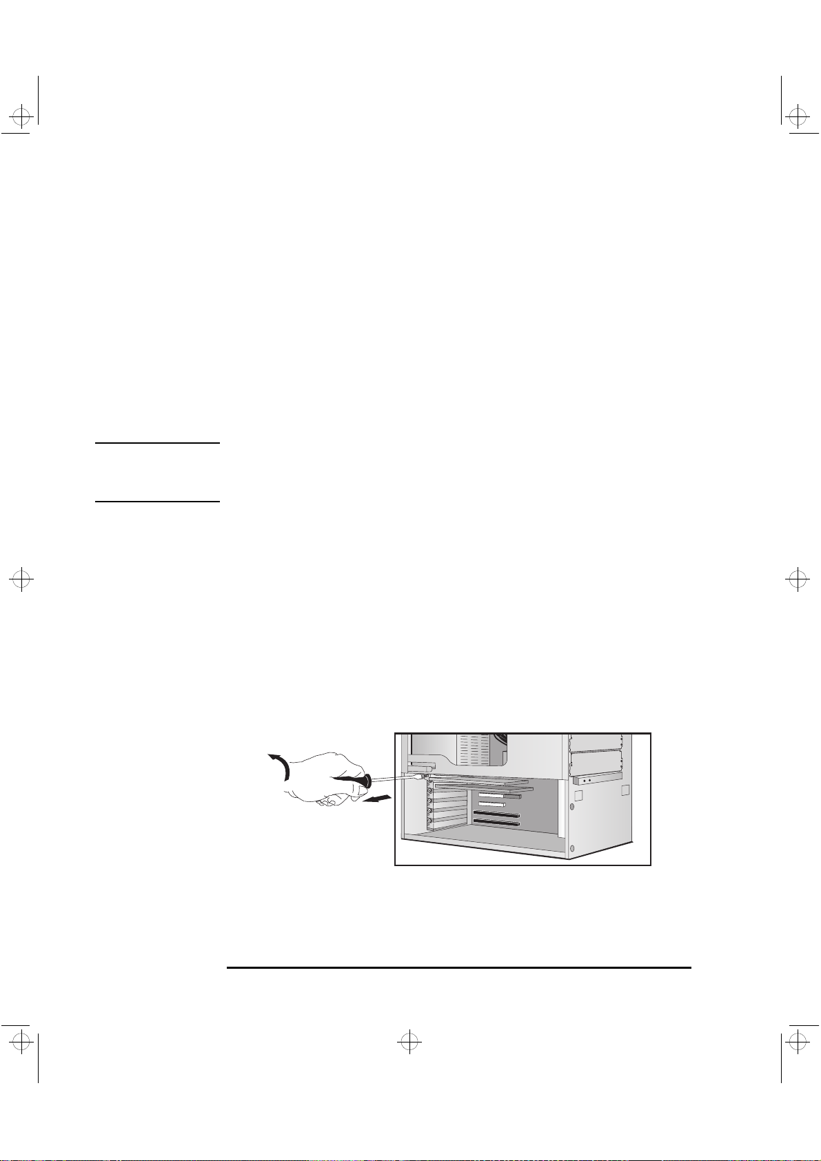
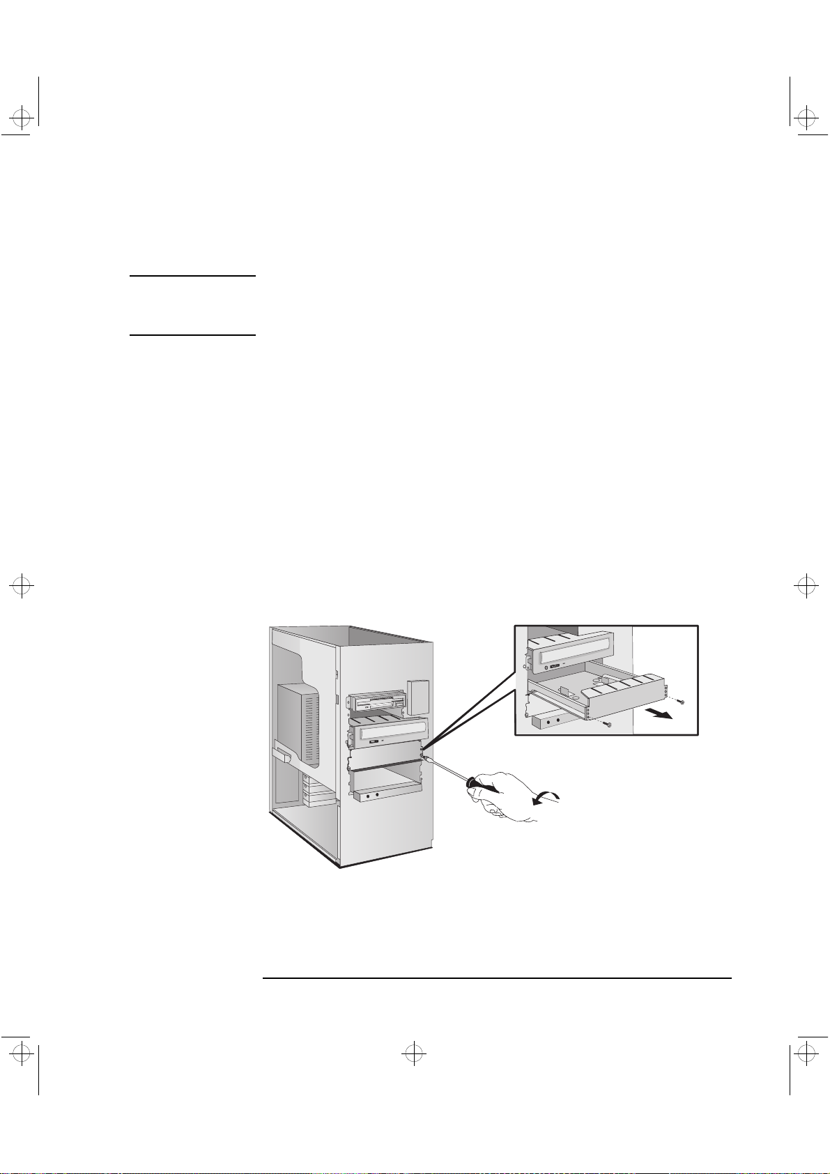
6 Unscrew and remove an unused drive tray.
Remove the
drive tray
English 43
Page 60

crystal.bk : cryst-2.fb4 Page 44 Monday, March 23, 1998 4:09 AM
2 How to Install Accessories Inside Your PC Workstation
Installing Mass Storage Devices
7 Mount the drive on the tray as shown below.
Set the drive on
the tray
Fix the drive to
the tray
8 Slide the drive tray into the drive shelf and secure it.
Slide the drive tray
into the drive shelf
44 English
Page 61

crystal.bk : cryst-2.fb4 Page 45 Monday, March 23, 1998 4:09 AM
2 How to Install Accessories Inside Your PC Workstation
9 Locate the appropriate data cable for the disk drive.
Wide SCSI devices should be
connected to a free SCSI connector
on the SCSI cable (you can add up
to five SCSI devices).
IDE drives should be connected to a
free IDE connector on the IDE cable
(you can add up to two IDE devices).
Installing Mass Storage Devices
Up to 13 external SCSI devices can be
connected via the external SCSI
connector.
10 Connect the data and power cables to the rear of the device. (The
connectors are shaped to go in one way only.)
Data Cable
11 Slide the power supply back into position, and tighten the four self-
retaining screws (see page 30).
Narrow SCSI devices should be
connected to a free SCSI connector on
the SCSI cable (you can add up to two
SCSI devices).
Power Cable
English 45
Page 62
crystal.bk : cryst-2.fb4 Page 46 Monday, March 23, 1998 4:09 AM
2 How to Install Accessories Inside Your PC Workstation
Installing Mass Storage Devices
12 Replace the HP UltraFlow airflow guide and reconnect the fan to the
system board (see the illustration on page 29).
13 Install any other accessories before replacing the cover and
completing the installation.
14 Follow the instructions below to complete the installation.
Completing the Installation of a Hard Disk Drive
When a SCSI Hard Disk
Drive Is Installed
When an IDE Drive
Is Installed
1 Switch on the computer.
2 To ensure compatibility, use the FDISK utility to delete any
partitions on the new hard disk.
3 Re-boot the computer.
Refer to the operating system documentation for information on
formatting a drive.
1 Switch on the computer.
2 To display the device in POST, press while the PC Workstation
re-starts.
3 If an error message appears, follow the instructions provided by the
Error Message Utility. When prompted, press to run the Setup
program.
4 Select the Advanced menu, and the IDE Devices submenu. In the
Primary Master item, check that the details for the device have been
correctly detected by the Setup program.
5 Press to save and exit Setup.
Refer to the operating system documentation for information on
formatting a drive.
NOTE If an IDE drive is removed, switch on the computer. The system BIOS
will detect that the device is missing. Press to confirm that you want
to remove the device. The system configuration will be updated
automatically.
46 English
Page 63

crystal.bk : cryst-2.fb4 Page 47 Monday, March 23, 1998 4:09 AM
2 How to Install Accessories Inside Your PC Workstation
Installing a Drive in a Front-Access Shelf
These instructions explain how to install a drive (such as a flexible disk
drive, a CD-ROM drive, CD-RW drive, or a tape drive) in one of the
front-access drive shelves. You should also refer to the manual supplied
with the drive for any additional installation instructions.
Installing Mass Storage Devices
Before Installing an
IDE Device
Before Installing a
SCSI Device
Refer to the drive’ s installation guide to see if you must set jumpers or if
there is a special installation procedure to follow.
If you are installing a SCSI device, refer to the section “Before Installing
a SCSI Hard Disk” on page 40 before using the following instructions.
1 Disconnect the computer’s power cord and any telecommunications
cable.
2 Remove the computer’s cover (see page 25).
3 Slide out the power supply to provide better access to the disk drive
cables (see page 29).
4 If installing a drive in a 5.25-inch wide shelf, remove the drive tray
and put it in a safe place.
Remove the
drive tray if
installing a
5.25-inch
drive
Mounting Rails
Slide the drive
into position
5 Slide the drive into the shelf.
6 Secure the drive in position using the screws provided with the drive.
English 47
Page 64

n
o
crystal.bk : cryst-2.fb4 Page 48 Monday, March 23, 1998 4:09 AM
2 How to Install Accessories Inside Your PC Workstation
Installing Mass Storage Devices
7 Locate the appropriate data cable for the device.
Wide SCSI devices should be
connected to a free SCSI connector
on the SCSI cable (you can add up
to five SCSI devices).
IDE drives should be connected to a
free IDE connector on the IDE cable
(you can add up to two IDE devices).
Up to 13 external SCSI devices can be
connected via the external SCSI
connector.
8 Connect the data and power cables to the rear of the device. (The
connectors are shaped to go in one way only.)
Data Cable
9 Slide the power supply back into position, and tighten the four self-
retaining screws (see page 30).
Narrow SCSI devices should be
connected to a free SCSI connector o
the SCSI cable (you can add up to tw
SCSI devices).
Power Cable
48 English
Page 65

crystal.bk : cryst-2.fb4 Page 49 Monday, March 23, 1998 4:09 AM
2 How to Install Accessories Inside Your PC Workstation
10 Remove the plastic panel from the cover by pulling the panel from
the left and unhinging its right-hand side. Store the panel in a safe
place.
Installing Mass Storage Devices
Unclip and lift out
the plastic panel
When an IDE CD-ROM
Drive Is Installed
When a Flexible Disk
Drive Is Installed
11 Install any other accessories before replacing the cover and
completing the installation.
Completing the Installation of a Drive
1 Switch on the computer and press when
2 In the Setup program, select the Advanced menu, the IDE Devices
submenu. Check that the CD-ROM drive has been detected on the
IDE channel.
3 Press to save and exit the program.
1 Switch on the computer and press when
2 In the Setup program, select the Advanced menu, the Flexible Disk
Drives submenu, and check that the drive has been detected.
3 Press to save and exit the program.
Setup
Setup appears.
appears.
English 49
Page 66

crystal.bk : cryst-2.fb4 Page 50 Monday, March 23, 1998 4:09 AM
2 How to Install Accessories Inside Your PC Workstation
Installing Accessory Boards
Installing Accessory Boards
CAUTION Static electricity can damage electronic components. Turn OFF all
equipment. Don’t let your clothes touch the accessory. To equalize the
static electricity, rest the accessory bag on top of the computer while
you are removing the accessory from the bag. Handle the accessory as
little as possible and with care.
The PC Workstation has the following accessory board slots:
Slot AT 2 (the bottom slot) for full-length 16-bit ISA boards
•
Slot AT 1/PCI 4 for either a 16-bit ISA board or a full-length 32-bit
•
PCI board
Slot PCI 3 can be used for a full-length 32-bit PCI board (and also
•
features the RAIDport
Slot PCI 2 for a full-length 32-bit PCI board
•
Slot PCI 1 for a full-length 32-bit PCI board
•
Slot AGP for the video adapter board
•
connector)
™
Installing the Board
1 Disconnect the computer’s power cord and any LAN connection or
telecommunications cable.
NOTE PCI boards are configured automatically when installed in the
PC Workstation.
2 Remove the computer’s cover ( "Removing and Replacing the Cover",
on page 25) and carefully place the PC Workstation on its side.
3 Find an empty slot. refer to "System Connectors and Switches", on
page 96. to identify the location of the slot type you want to use
(ISA or PCI).
Some boards may have preferred locations and special installation
instructions detailed in their manuals.
50 English
Page 67

crystal.bk : cryst-2.fb4 Page 51 Monday, March 23, 1998 4:09 AM
2 How to Install Accessories Inside Your PC Workstation
4 Unscrew and remove the slot cover. Store it in a safe place.
If the slot cover is tight, loosen the screws on the adjacent slots.
Unscrew and remove
the slot cover
Installing Accessory Boards
5 Hold the board horizontally by its “top” edge. Slide it into the board
guide of the chosen slot. Do not bend the board.
Slide the accessory
board into position
6 Align the board’s connector with the slot’s socket. Firmly press the
board into the socket. Ensure the board’s connector engages
completely with the socket and does not touch components on other
boards.
English 51
Page 68

crystal.bk : cryst-2.fb4 Page 52 Monday, March 23, 1998 4:09 AM
2 How to Install Accessories Inside Your PC Workstation
Installing Accessory Boards
7 Secure the board by replacing the slot cover screw.
If you loosened the screws on adjacent slots, remember to tighten
them.
Secure the board
in position
8 Install any other accessories before replacing the cover (see page
27). Reconnect all cables and power cords.
Completing the
Installation of an ISA
Accessory Board
If you have installed an ISA accessory board that uses any interrupt,
you must run the Setup program and reserve the IRQ for the accessory
board. This allows PCI devices to be automatically configured.
1 Turn on the PC Workstation and press when
Setup
appears.
2 In the Setup program, select the Advanced menu and the PCI Slot
Configuration submenu. A list of IRQs and the devices that use them
are displayed. Highlight the IRQ field you want to change, for
example
IRQ 11
.
3 You can use the space bar or press or to make the IRQ
available for PCI (
(
Reserved).
Available) or make it unavailable for PCI
4 Press to save any changes you made and exit the Setup program.
NOTE You should always leave at least one IRQ available for use by the
integrated PCI devices.
52 English
Page 69

crystal.bk : cryst-2.fb4 Page 53 Monday, March 23, 1998 4:09 AM
2 How to Install Accessories Inside Your PC Workstation
Installing a Processor
Some operating systems support a second processor for enhanced
performance. Contact your authorized reseller for up-to-date
information.
NOTE The Setup program provides an option to disable the second processor.
1 Disconnect the computer’s power cord and any LAN or
telecommunications cable.
2 Remove the computer’s cover (see page 25).
3 Press the retaining buttons on each side of the HP UltraFlow airflow
guide and lift it partly out of the PC Workstation’s case.
Installing a Processor
Fan connection to
system board
HP UltraFlow
Airflow Guide
Retaining button
4 Remove the fan connection to the system board and lift the airflow
guide completely out of the PC Workstation’s case.
5 Slide out the power supply to improve access to the processor
sockets (see page 29) and carefully place the PC Workstation on
its side.
6 Remove the transparent airflow guide covering the processor
sockets.
English 53
Page 70

crystal.bk : cryst-2.fb4 Page 54 Monday, March 23, 1998 4:09 AM
2 How to Install Accessories Inside Your PC Workstation
Installing a Processor
7 The system board has two processor sockets and a VRM slot for each
processor. If you are changing the existing processor, remove it from
the socket by squeezing the tabs at the top and bottom of the
processor and gently pulling the processor away from the system
board. Then remove the VRM for the processor.
If you are installing a processor in the second socket, remove the
terminator.
NOTE Installing a faster processor than the one supplied with your
PC Workstation will void the warranty.
8 Slide the new processor into the processor socket and push gently
until it snaps into place (the processor can only go in one way). If
you are installing a second processor, remove the card in the second
processor socket and slide the processor into the empty processor
socket (next to the existing processor).
VRM module
Processor
9 Insert the VRM for the processor in the VRM socket.
10 Replace the transparent section of the HP UltraFlow airflow guide
covering the processor sockets.
11 Slide the power supply back into the computer and tighten the four
self-retaining screws.
12 Turn the PC Workstation upright and replace the HP UltraFlow
airflow guide.
13 Reconnect the fan to the system board.
54 English
Page 71

crystal.bk : cryst-2.fb4 Page 55 Monday, March 23, 1998 4:09 AM
2 How to Install Accessories Inside Your PC Workstation
Completing the
Installation of a
Processor
NOTE If two processors are installed, both must operate at the same bus speed
1 Verify that the system board bus speed switches are correctly
configured for the processor.
and processor speed. Refer to the manual supplied with the processor
to verify which bus and processor speeds are supported.
Installing a Processor
Switch 1 Switch 2 Switch 3 Switch 4 Switch 5 External
Bus Speed
1
UP
UP UP DOWN UP UP 100 MHz 400 MHz
UP UP DOWN UP DOWN 100 MHz 450 MHz
UP UP DOWN DOWN UP 100 MHz 500 MHz
1. UP=OFF, DOWN=ON.
UP UP DOWN DOWN 100 MHz 350 MHz
2 Install any other accessories before completing the installation of the
processor.
3 Replace the cover (see page 27).
4 Turn on the computer and check that the new processor is
recognized by the power-on system-test.
NOTE To fully benefit from dual processing, you will need to re-install
Windows NT 4.0 on your PC Workstation.
Processor
Speed
English 55
Page 72

crystal.bk : cryst-2.fb4 Page 56 Monday, March 23, 1998 4:09 AM
2 How to Install Accessories Inside Your PC Workstation
Installing a Processor
56 English
Page 73

crystal.bk : cryst-3.fb4 Page 57 Monday, March 23, 1998 4:09 AM
3
Troubleshooting Your PC Workstation
This chapter deals with problems you may encounter when using your
PC Workstation.
Page 74

crystal.bk : cryst-3.fb4 Page 58 Monday, March 23, 1998 4:09 AM
3 Troubleshooting Your PC Workstation
Solving Problems
Solving Problems
This chapter can help you solve most problems you might have with
your PC Workstation.
If you are unable to solve your problem after following the advice in
this chapter, refer to "Hewlett Packard Support and Information
Services", on page 139.
HP Summary Screen
The HP Summary Screen provides information about your PC
Workstation’s current configuration. To view the Summary Screen,
press just after your PC Workstation is turned on and while the
logo is displayed during the Power-on-Self-Test (POST). Refer to page
101 for more information.
Using HP MaxiLife to
Diagnose Problems
Your HP Hardware
Diagnostics Utility
HP Visualize FX4
Diagnostics Tool
HP Diagnostics
You can use HP MaxiLife to help you diagnose problems with your PC
W orkstation. For more information on using HP MaxiLife, refer to "Using
HP MaxiLife to Diagnose Problems", on page 75.
A HP Diagnostics utility is either preloaded on your hard disk drive or is
available on the World-Wide-Web.
With this utility you can diagnose hardware-related problems that
may arise with your PC Workstation. For more information, “HP
Hardware Diagnostics Utility” on page 79.
You can use this diagnostics tool, available on the driver’s CD-ROM, to
help you diagnose problems with your HP Visualize FX4 graphics
solution.
Note that this diagnostics tool can only be used with Windows NT.
58 English
Page 75

crystal.bk : cryst-3.fb4 Page 59 Monday, March 23, 1998 4:09 AM
If Your PC Workstation Does Not Start Properly
Use this section if your PC Workstation does not start properly when
you turn it on, and you experience one of the following symptoms:
Your PC Workstation’s display is blank and there are no error
•
messages.
You cannot change any values in the Setup program.
•
A POST error message is displayed.
•
An error message and an icon appears on the LCD screen (refer
•
to “Using HP MaxiLife to Diagnose Problems” on page 75).
Display is Blank and There Are No Error Messages
3 Troubleshooting Your PC Workstation
If Your PC Workstation Does Not Start Properly
Check External Items
If your display is blank and there are no error messages when you turn
on your PC Workstation, follow this procedure:
1 Check the LCD screen (refer to “Using HP MaxiLife to Diagnose
Problems” on page 75).
2 Check external items.
3 Check internal items.
4 Rebuild your PC Workstation’s components (see page 61).
Be sure the following external items are functioning properly:
Check that the computer and display are turned on. (The power light
•
should be illuminated.)
Check the display’s contrast and brightness settings.
•
Make sure that all cables and power cords are firmly plugged in.
•
Make sure the power outlet is working.
•
English 59
Page 76

crystal.bk : cryst-3.fb4 Page 60 Monday, March 23, 1998 4:09 AM
3 Troubleshooting Your PC Workstation
If Your PC Workstation Does Not Start Properly
Check Internal Items
If the PC W orkstation still does not start properly, follow this procedure
to check the internal items:
1 Turn off the display, the computer, and all external devices.
2 Unplug all power cords and cables, noting their positions. Disconnect
the PC Workstation from any telecommunications network.
3 Remove the cover.
4 Check the following items:
LCD Error
Messages
- Check all internal cables. Ensure they are correctly attached and
Power CPU 1
Power CPU 2
CPU Freq Check that the processor speed
CPU error Reset the PC Workstation or power-off
- Check that the memory modules are
- Check that accessory boards are firmly
- Verify that any switches and jumpers
- Check that the switches on the system
Temp disk
Temp CPU
Temp IO slot
Fan CPU
Fan disk
Fan IO slot
Power supply Check that power supply is properly
Check that the processor and VRM are
correctly installed.
switches have been set correctly.
the LAN.
correctly installed.
seated in their slots.
on the accessory boards are properly
set.
board are properly set.
Check fans and that air flow guide is
not blocked.
Check that fans are installed correctly. Refer to the illustration on page 29.
connected.
Action Reference
firmly in place.
Refer to “Installing a Processor”
page 53.
Refer to “System Board Switches”
page 99.
Refer to“Your PC Workstation’s
Hardware Control Panel” on page 9.
Refer to “Installing Memory” page 31.
Refer to “Installing Accessory Boards”
page 50.
Refer to the manuals that came with
each board.
Refer to “System Board Switches”
page 99.
Refer to the illustration on page 29.
Refer to “Replacing the Power Supply
after Installing Accessories” on page 30
60 English
Page 77
crystal.bk : cryst-3.fb4 Page 61 Monday, March 23, 1998 4:09 AM
5 Replace the cover.
6 Reconnect all cables and power cords.
7 Turn on the display and computer.
3 Troubleshooting Your PC Workstation
If Your PC Workstation Does Not Start Properly
Rebuild Your PC
Workstation’s
Components
If your PC Workstation still does not start properly, remove all boards
and accessories, except the hard disk drive and video board. Start the
PC Workstation. If the PC Workstation now works, add the boards and
accessories one at a time to determine which one is causing the
problem.
If you are Unable to Change any Values in Setup
Ensure that you are using the correct password.
If a POST Error Message is Displayed
The Power-On-System-Test (POST) can detect both an error and a
change to the configuration. In either case, an error code and short
description is displayed. Depending on the kind of error, you will have
one or more of these choices available on screen:
Press to ignore the message and continue.
•
Press to run Setup and correct a system configuration error. HP
•
recommends that you correct the error before proceeding, even if
the PC Workstation appears to start successfully.
Press to accept (validate) the change and update Setup’s
•
configuration information.
Press to see more details about the message. After viewing
•
these details, you will be returned to the original POST display
screen. If the message is actually a change to the configuration you
have made (for example, you have just removed some memory), you
can then press to accept the change and update Setup’s
configuration information. Otherwise, press to ignore the
message and continue, or press to run Setup and correct a
system configuration error. (The number of choices you will have
available are dependent on the kind of error.)
English 61
Page 78
crystal.bk : cryst-3.fb4 Page 62 Monday, March 23, 1998 4:09 AM
3 Troubleshooting Your PC Workstation
If Your PC Workstation Does Not Start Properly
Clearing the
PC Workstation’s
Configuration Memory
If the PC W orkstation then starts, but POST still persists in reporting an
error, clear the current configuration memory values and reinstall the
built-in default values:
1 Turn off the PC Workstation, disconnect the power and cables, and
remove the cover. Disconnect the PC Workstation from any
telecommunications network.
a Set the system board switch 6 (CLEAR CMOS) DOWN to clear
the configuration.
b Replace the cover, and reconnect only the power cable.
c Turn on the PC Workstation. This will erase the CMOS memory.
d Wait until the PC Workstation has started. A message will be
displayed similar to this:
“Configuration has been cleared, set switch Clear
CMOS to the open position before rebooting.”
e Turn off the PC Workstation, disconnect the power cable, and
remove the cover.
f Set the system board switch 6 (CLEAR CMOS) UP to retain the
configuration.
2 Replace the cover, and reconnect the power and cables.
3 Switch on the PC Workstation. An error message will be displayed
similar to the following:
On your monitor: On your PC Workstation’s LCD:
Incorrect PC Configuration Error! POST 0012
The PC Workstation will stop. Press (to view the system
errors) and then press .
4 Run Setup by pressing . CMOS default values will be
automatically downloaded and saved.
5 Make any other changes you want and press to save the
configuration and exit from Setup.
62 English
Page 79

crystal.bk : cryst-3.fb4 Page 63 Monday, March 23, 1998 4:09 AM
If You Cannot Turn Off Your PC Workstation
Use this section if you cannot turn off your PC Workstation, the power
indication light is red, and you hear a “buzzing” sound.
Check if your PC Workstation is locked, whereby “power-off” is not
•
allowed. You will need to enter a password to unlock the
PC Workstation (refer to “Setting Passwords” on page 18 for more
information).
Check if you are in a suspend/standby mode, in which case a “power-
•
off” would risk a loss of information/data (refer to the Power Menu in
the HP Setup program).
CAUTION If you press the On/Off button for four seconds, the system will be
automatically turned off. Note that this does not shut down the
operating system properly.
3 Troubleshooting Your PC Workstation
If You Cannot Turn Off Your PC Workstation
English 63
Page 80

crystal.bk : cryst-3.fb4 Page 64 Monday, March 23, 1998 4:09 AM
3 Troubleshooting Your PC Workstation
If Your PC Workstation Has a Hardware Problem
If Your PC Workstation Has a Hardware Problem
This section describes what to do if you have problems with your
display, disk drives, printer, accessory boards, keyboard, or mouse.
Display Does Not Work Properly
If Your Display Is
Blurred or Unreadable
If Nothing Is Displayed
On the Screen
If you have selected the wrong display type in your operating system,
the display screen may become blurred or unreadable. To correct this
problem, select the correct display by using the procedures in the
operating system on your PC Workstation. Refer to your
PC Workstation’s operating system documentation for details.
If nothing is displayed on the screen, but the PC W orkstation starts and
the keyboard, disk drives, and other peripheral devices seem to operate
properly:
Check your PC Workstation’s LCD screen to help you diagnose the
•
problem. For more information, refer to "Using HP MaxiLife to
Diagnose Problems", on page 75.
Make sure that the display is plugged in and switched ON.
•
Check that the brightness and contrast controls are properly set.
•
Ensure that the display video cable is correctly connected.
•
Switch off the display, and unplug it from the power outlet.
•
Disconnect the video cable and examine the video cable connector
•
pins. If the pins are bent, carefully straighten them.
Check that the video upgrade is properly installed if you have one.
•
If the display works correctly during the Power-On-Self-Test
•
(POST), but goes blank when Windows starts, check that you have
enough memory for the video mode you have selected. Boot the
operating system in VGA mode (available with some systems).
If your screen’s refresh rate is set too high, the screen might be
•
blank. Check the refresh settings to ensure they are not too high.
64 English
Page 81
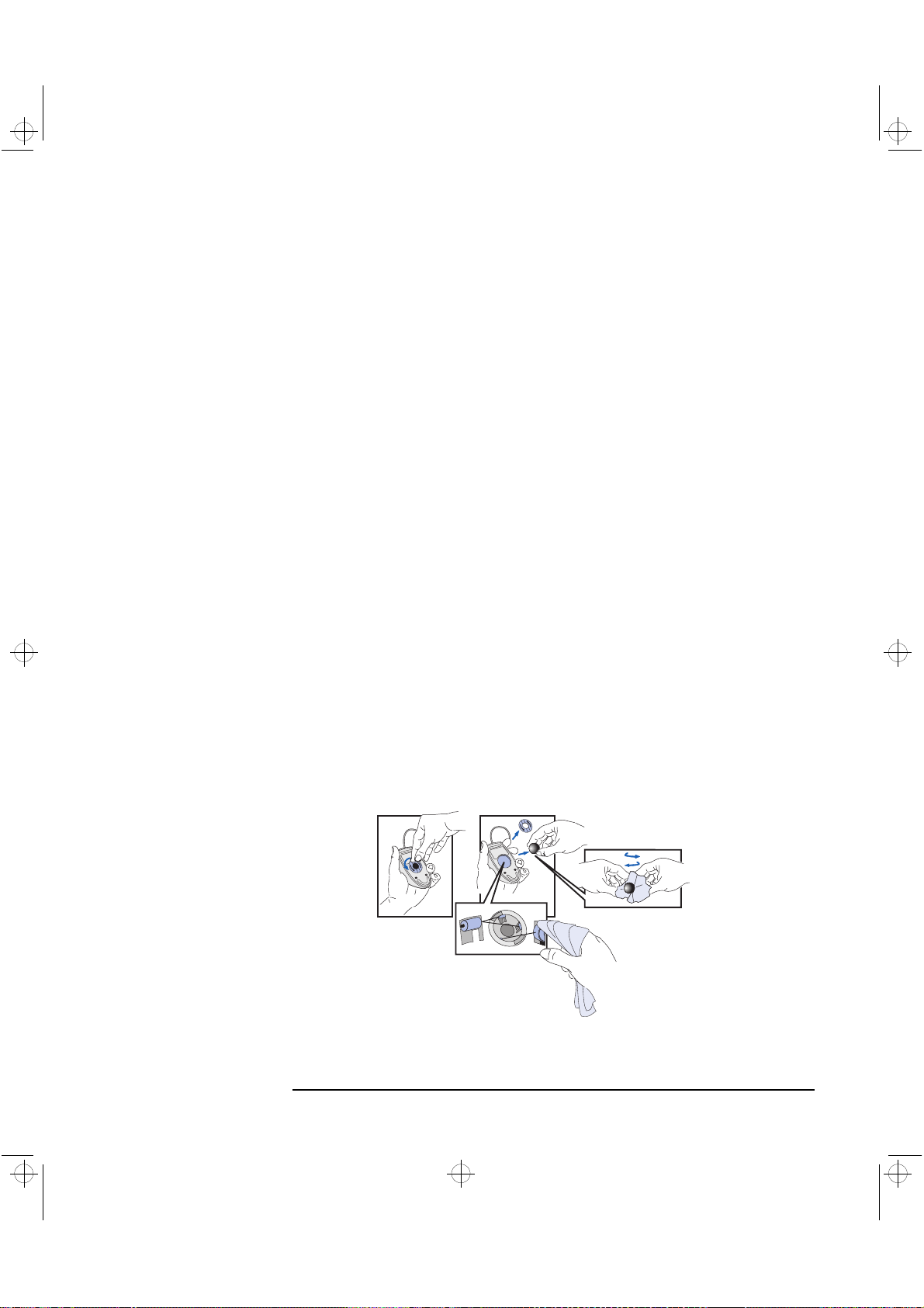
crystal.bk : cryst-3.fb4 Page 65 Monday, March 23, 1998 4:09 AM
3 Troubleshooting Your PC Workstation
If Your PC Workstation Has a Hardware Problem
Other Display Problems
If the display image is not aligned with the screen, use the display’s
controls to center the image (refer to the display manual for
instructions). If the screens generated by the applications do not appear
to be correct, check the application’s manual to find out which video
standard is required. Also check your display manual to find out which
refresh rate is required. Use your operating system’s procedures, to
select the correct refresh rate.
If Your Keyboard Does Not Work
Ensure that the keyboard is correctly connected (a keyboard icon
•
will be displayed on your screen if the keyboard is not connected).
If you turn on your PC Workstation, the operating system boots, and
•
the keyboard is correctly connected but still not available, the
power-on password may be set to “keyboard locked”. You will need
to enter a password to unlock the keyboard and mouse. You can
change this setting in the Setup program. Refer to the Power Menu
in the HP Setup program.
If Your Mouse Does Not Work
Ensure that the mouse is correctly connected.
•
Ensure that the mouse driver supplied with the preloaded software
•
is installed correctly.
Clean the mouse ball and rollers as shown in the figure below (use a
•
non-residual contact cleaner).
Cleaning the mouse rollers
Cleaning the mouse ball
English 65
Page 82

crystal.bk : cryst-3.fb4 Page 66 Monday, March 23, 1998 4:09 AM
3 Troubleshooting Your PC Workstation
If Your PC Workstation Has a Hardware Problem
If Your Printer Does Not Work
Make sure the printer’s power switch is ON.
•
Verify that the power cord is plugged into the power outlet and the
•
printer.
Verify that you have the correct cable for the printer. Make sure that
•
it is securely connected to the correct connector (port) on the
PC Workstation and printer.
Check that the printer is online.
•
Examine the paper feed mechanism for a paper jam.
•
Make sure that the printer is configured correctly for the
•
PC Workstation and for the application.
Ensure the PC Workstation’s port has been correctly configured
a
using Setup.
Make sure the printer is correctly set up in your operating
b
system’s configuration.
Ensure the application program’s “print” menu has been correctly
c
set up. (Refer to the manual supplied with the application
software.)
Check that the PC Workstation’s port is working properly by running
•
another peripheral connected to the port.
If you receive an error message, refer to the printer’s manual for help.
•
If the Flexible Disk Drive Does Not Work
Check that you are using a formatted diskette and it is inserted
•
correctly.
Check you are using a diskette that is the correct density.
•
Check that the flexible disk drive is correctly configured in the Setup
•
program (Advanced > Flexible Disk Drive).
Check that the flexible disk drive is not disabled in the Setup
•
program (Advanced > Flexible Disk Drive).
66 English
Page 83

crystal.bk : cryst-3.fb4 Page 67 Monday, March 23, 1998 4:09 AM
Check that the Flexible Disks item and the Write on Flexible Disks
•
item are not set to locked in the Setup program (Security > Hardware Protection).
Clean the flexible disk drive using a diskette cleaning kit.
•
Check that the disk power and data cables are correctly connected.
•
If the Hard Disk Drive Does not Work
Check that the disk power and data cables are correctly connected
•
(Refer to “Connecting Devices” on page 37).
For an IDE drive, check the IDE Device’s configuration settings in
•
the Setup program (Advanced > IDE Devices).
For an IDE drive, check the Hardware Protection settings in the
•
Setup program (Security > Hardware Protection).
3 Troubleshooting Your PC Workstation
If Your PC Workstation Has a Hardware Problem
If the Hard Disk Activity
Light Does Not Work
For an IDE drive, check the Boot Device Security settings in the
•
Setup program (Security > Boot Devices Security).
For a SCSI drive, check the SCSI Interface settings in the Setup
•
program at Advanced > Internal Wide 16-bit SCSI or External\
Internal 16\8-bit SCSI and in the SCSISelect Utility (Adaptec)or the
Configure SCSI Utility (Symbios).
If the hard disk activity light does not flicker when the PC Workstation
is accessing the hard disk drive:
Check that the control panel connector is firmly attached to the
•
system board.
Check that the disk power and data cables are correctly connected.
•
English 67
Page 84

crystal.bk : cryst-3.fb4 Page 68 Monday, March 23, 1998 4:09 AM
3 Troubleshooting Your PC Workstation
If Your PC Workstation Has a Hardware Problem
If the CD-ROM Drive Has a Problem
WARNING Be sure to disconnect the power cord and any telecommunication
cables from your computer before you remove the cover to check the
cable connections or jumper settings.
To avoid electric shock and harm to your eyes by laser light, do not
open the CD-ROM drive enclosure. The drive should be serviced by
qualified service personnel only. Refer to the label on the drive for
power requirements and wavelength. Do not attempt to make any
adjustment to the unit. This PC Workstation is a class 1 laser product.
The CD-ROM Drive Does not Work
Check that the cables have been properly connected.
•
Check that the CD-ROM is inserted in the drive.
•
Check the IDE Devices configuration settings in the Setup program
•
(Advanced > IDE Devices).
Check the Hardware Protection settings in the Setup program
•
(Security > Hardware Protection).
Check the Boot Device Security settings in the Setup program
•
(Security > Boot Devices Security).
Check that the Integrated Bus IDE Adapters item is set to Both in the
•
Setup program (Advanced > IDE Devices).
68 English
Page 85

crystal.bk : cryst-3.fb4 Page 69 Monday, March 23, 1998 4:09 AM
No Sound from the CD-ROM Drive
If you are having problems with sound when playing a CD:
Check that the volume control (if present) on the CD-ROM or
•
CD-RW drive front panel is not set to the minimum.
Ensure that the disk in the drive is an audio disk and not a photo CD
•
or data CD.
If using headphones or external speakers, check that they are
•
properly connected to the Audio Front Panel (not to the audio jack
for the CD-ROM).
Check that the CD Audio switch is selected in the mixer (if selected
•
a speaker icon will appear in the taskbar).
Check that the CD audio cable is correctly installed and is connected
•
to the system board.
3 Troubleshooting Your PC Workstation
If Your PC Workstation Has a Hardware Problem
The CD-ROM Drive is Idle
If the drive does not appear to be working, try accessing the disk by
clicking on the drive icon or drive letter assigned to the drive by your
operating system.
English 69
Page 86

crystal.bk : cryst-3.fb4 Page 70 Monday, March 23, 1998 4:09 AM
3 Troubleshooting Your PC Workstation
If Your PC Workstation Has a Hardware Problem
The CD-ROM Drive Does not Open
If you have difficulty removing a CD-ROM disk from the CD-ROM drive
(during a power failure for example), you can use the manual eject
button. T o eject a CD-ROM disk using the manual eject button, proceed
as follows:
1 If the CD-ROM drive manual eject button is not visible, remove the
front bezel covering the drive. The manual eject button is inside a
small hole in the front of the CD-ROM drive.
2 With a thin, solid rod, such as the end of a paper clip, push the drive’s
manual eject button.
Using the manual eject feature.
The picture shows two possible
locations of the manual eject
button.
3 The drive door is released, opening slightly. Carefully pull it open
fully and retrieve the disk.
4 To close the drive door, push it gently closed without forcing it. The
drive door may not close completely until it is fully functional (for
example, when the power comes back on).
5 If required, replace the drive’s front bezel.
70 English
Page 87

crystal.bk : cryst-3.fb4 Page 71 Monday, March 23, 1998 4:09 AM
If an Accessory Board Does not Work
Carry out the following checks:
Check that the accessory board has been firmly installed in the slot.
•
Check that the accessory board has been correctly configured.
•
Check that the accessory board is not using memory, I/O addresses,
•
an IRQ, or DMA also used by the PC Workstation. Refer to “IRQs,
DMAs, and I/O Addresses Used by Your PC Workstation” on page 86
for more information.
3 Troubleshooting Your PC Workstation
If Your PC Workstation Has a Hardware Problem
English 71
Page 88

crystal.bk : cryst-3.fb4 Page 72 Monday, March 23, 1998 4:09 AM
3 Troubleshooting Your PC Workstation
If Your PC Workstation Has a Software Problem
If Your PC Workstation Has a Software Problem
If You Have Forgotten Your Password
❒ If you forget the User Password and the Administrator password is set
and known:
1 Switch off the PC Workstation.
2 Restart the PC Workstation.
3 Wait for the message
4 Press to start Setup.
5 Type the Administrator password to enter Setup.
6 Select Security, the User Password submenu, and set a new User
password.
7 Press to save the new User password and exit Setup.
❒ If you forget both the User password and the Administrator password:
1 Switch off the PC Workstation and remove the computer’s cover
(refer to page 25).
2 Set switch 7 (PSWRD) on the system board switch block to ON
(DOWN). Refer to page 99 for the switch location.
3 Replace the PC Workstation’s cover and switch on the
PC Workstation. Allow it to complete its startup routine.
4 Switch off the PC Workstation and remove the cover.
5 Reset switch 7 (PSWRD) to OFF (UP).
6 Replace the computer’s cover (refer to page 27).
Setup.
7 Switch on the PC Workstation and allow it to startup.
8 Press when prompted to use Setup.
9 Set new User and Administrator passwords.
10 Press to save the new passwords and exit Setup.
72 English
Page 89

crystal.bk : cryst-3.fb4 Page 73 Monday, March 23, 1998 4:09 AM
If You Can’t Start the Setup Program
This may happen if the copy of the PC Workstation’s configuration
stored in memory is corrupted. You will need to erase this bad
configuration. Refer to “Clearing the PC Workstation’s Configuration
Memory” on page 62 for more information on how to do this.
If the Date and Time Are Incorrect
The date and time can be incorrect for the following reasons:
The time has changed to reflect the beginning or end of
•
Summer Time
The PC Workstation has been unplugged from the mains for too long
•
and the battery is discharged.
3 Troubleshooting Your PC Workstation
If Your PC Workstation Has a Software Problem
The on-board battery automatically recharges itself as soon as the
PC Workstation is plugged into a power outlet.
To change the date and time, use your operating system utilities or the
Setup program.
If Your Application Software Does Not Work
If the PC Workstation reports the system is OK and the indicator light
over the power switch is illuminated, but some software won’t run,
refer to the operating system and/or application software manuals.
If You Have a Network Problem
If you have a problem with your PC Workstation’s network, run the
HPIEDIAG utility provided on the HP CD-ROM that contains the LAN
drivers, supplied with your PC Workstation. This utility should be run
from a minimal DOS system, without any LAN drivers loaded—achieve
this by booting from a system floppy disk. (If your PC Workstation is
running Windows NT 4.0, you will need to create this system floppy
disk on another PC.)
1 Insert the system floppy disk in the floppy disk drive and re-boot
your PC Workstation.
English 73
Page 90
crystal.bk : cryst-3.fb4 Page 74 Monday, March 23, 1998 4:09 AM
3 Troubleshooting Your PC Workstation
If Your PC Workstation Has a Software Problem
2 Insert the CD-ROM containing the HPIEDIAG utility in the CD-ROM
drive.
3 Make the CD-ROM drive the current drive by typing, for example,
D: if D is the letter of your CD-ROM drive.
4 Change to the DIAG directory by typing:
5Start the HPIEDIAG utility by typing:
CD\LAN\DIAG
HPIEDIAG . Follow
.
the instructions on the screen.
Then check the configuration of the integrated Ethernet interface
using the Setup program. Refer also to the Network Administrator’s
Guide preloaded onto your PC Workstation.
If Your PC Workstation Has an Audio Problem
If you encounter problems with the audio on your PC Workstation,
refer to the Using Sound guide preloaded onto your PC Workstation.
74 English
Page 91
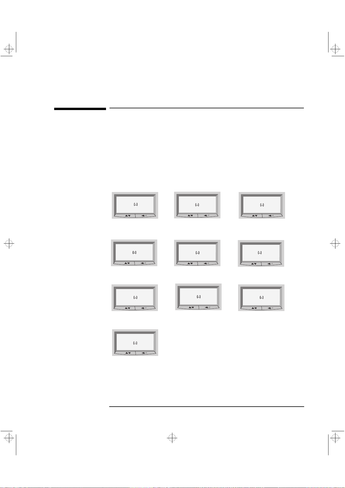
crystal.bk : cryst-3.fb4 Page 75 Monday, March 23, 1998 4:09 AM
Using HP MaxiLife to Diagnose Problems
Your HP LCD can help you to diagnose problems with your PC
W orkstation, even when you are unable to get your system and monitor
working properly.
3 Troubleshooting Your PC Workstation
Using HP MaxiLife to Diagnose Problems
Pre-Boot Checks
Note: Some error
messages displayed here
may not be available.
When you press your PC Workstation’s on/off button, HP MaxiLife will
check your sy stem before it initiates the start-up sequence. Y ou will see
one of the following screens on the LCD as these checks progress:
Error!
CPU Socket
Check that a CPU or terminator
is installed in the CPU slots
Error!
Power CPU 2
Check processor 2 VRM
installation.
Error!
No RAM
Check memory installation.
Error!
Power supply
Check power supply and
power cable connections.
Error!
Board PLL
Check system board.
Error!
No Video
Check that graphics card
is installed correctly.
Error!
Power CPU 1
Check processor 1 VRM
installation.
Error!
BIOS
Flash new BIOS.
Error!
RAM type
Check that installed RAM
types are compatible.
HP KAYAK XU
No errors occurred during preboot. POST is initiated.
English 75
Page 92

crystal.bk : cryst-3.fb4 Page 76 Monday, March 23, 1998 4:09 AM
3 Troubleshooting Your PC Workstation
Using HP MaxiLife to Diagnose Problems
POST Phase
Following these checks, the POST (Power-On Self Test) sequence is
initiated. One of the following screens will appear in this phase:
HP KAYAK XU
No errors occurred.
Error!
POST XXXX
A POST error occurred. Refer to “If a POST
Error Message is Displayed” on page 61 for
more information.
Other Features
HP MaxiLife can also be configured to:
Display the configuration details of your PC Workstation required to
•
obtain support (System info.)
Indicate POST (Power-On Self Test) steps during the power-on
•
phase (Boot steps)
Perform diagnostic tests on your PC Workstation’s various hardware
•
components and display the results (Diags).
To configure your HP LCD:
1 Ensure that your PC Workstation’s power cord is connected to a
grounded outlet.
In this state, your PC Workstation’s hardware management chip is
active, even if your system is not powered on.
2 Press one of the LCD control buttons. The following menu is
displayed.
System info
Boot steps
Next Go
Diags
Exit
Next Go
3 Use to scroll down through the menu items and to select the
required menu item.
76 English
Page 93
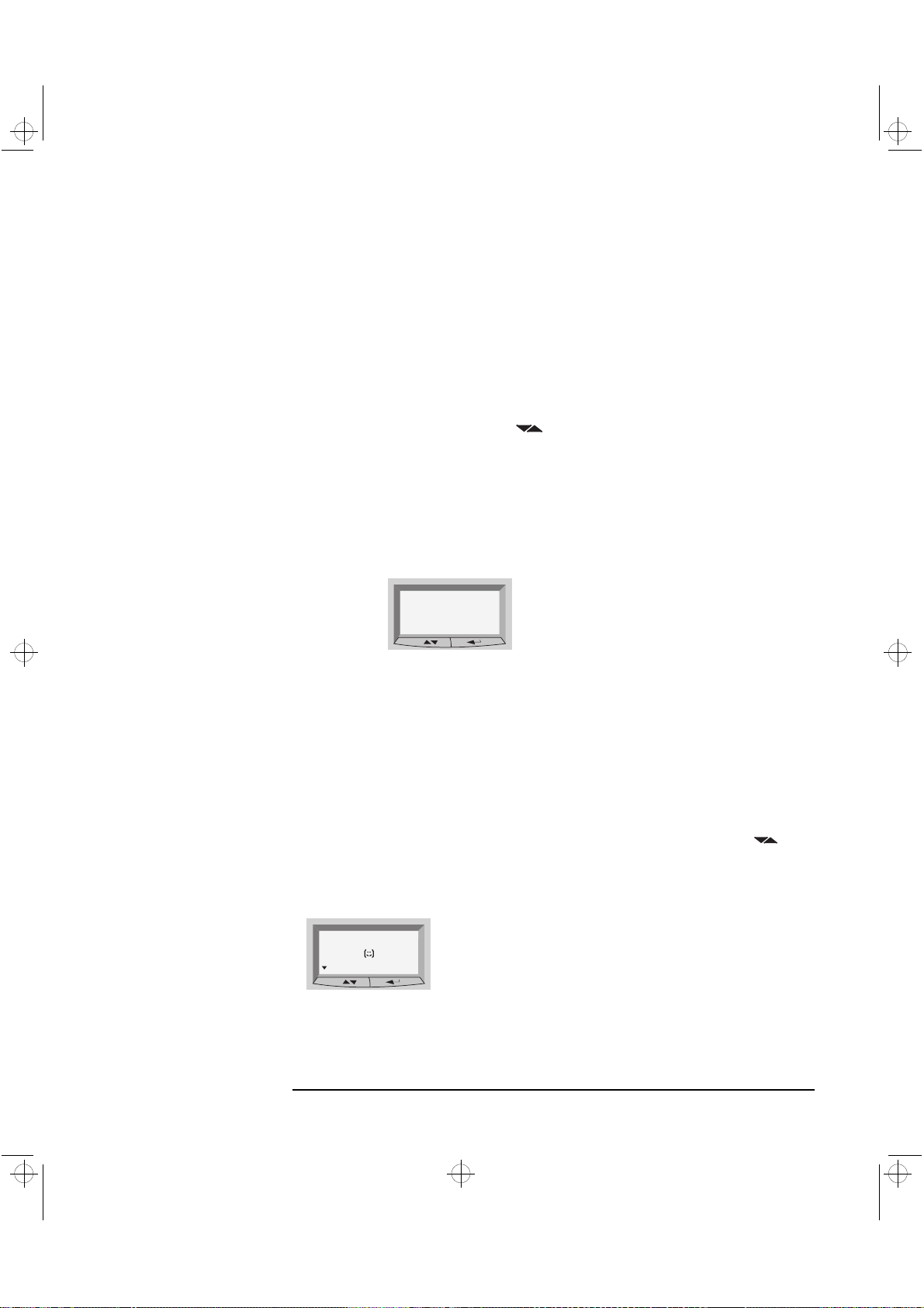
crystal.bk : cryst-3.fb4 Page 77 Monday, March 23, 1998 4:09 AM
3 Troubleshooting Your PC Workstation
Using HP MaxiLife to Diagnose Problems
System Info.
Boot Steps
Diags
System information is displayed on the LCD one screen at a time and
should detail the following:
• Bios version
• Number & speed of processors
• Number and capacity of memory
modules installed
• Serial Number
To view these details, use the button to scroll through the
information screens.
Where available, the Boot steps option will display all POST steps the
next time your PC Workstation is powered on. For support purposes,
POST steps are shown as POST codes and displayed on the LCD
as follows:
HP KAYAK XU
POST Code 24
Post steps will be displayed on the
LCD the next time your PC
Workstation is powered on.
If your PC Workstation is powered off when Diags is selected, the LCD
display s a second menu. To perform the diagnostics tests, select
from this menu to enable the hardware management chip to assess
on
Power
the status of your system’s components.
If your PC Workstation is already powered on, the diagnostic tests will
be performed as soon as you select Diags from the LCD’s main menu.
To view the test results for each system component, press the
control button.
If no component errors are detected, the following screen will appear.
COMPONENT
Next
No errors were detected.
English 77
Page 94
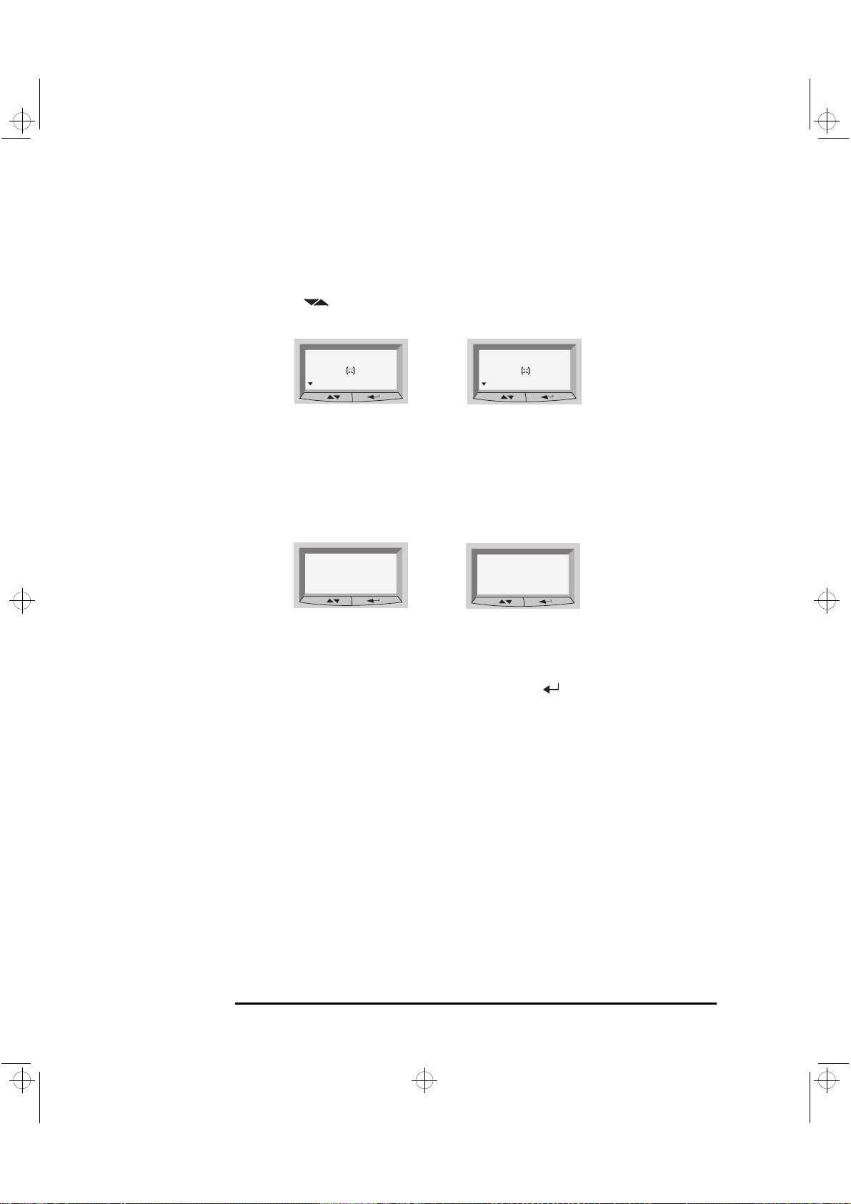
crystal.bk : cryst-3.fb4 Page 78 Monday, March 23, 1998 4:09 AM
3 Troubleshooting Your PC Workstation
Using HP MaxiLife to Diagnose Problems
If an error is detected, an error screen appears indicating the problem.
To continue viewing the test results of the other system components,
press the control button.
COMPONENT
Next
Fan CPU
Next
For example, if there is a problem with a fan, an alarm
will sound and the following error screen will appear.
For more information, refer to “Check Internal Items”
on page 60.
When the diagnostic tests are complete, one of the following screens is
displayed.
Diagnostics:
Done FAIL
Exit
System errors were
detected.
Diagnostics:
Done OK
Exit
No errors were detected.
You can exit the test session by pressing the button.
78 English
Page 95

crystal.bk : cryst-3.fb4 Page 79 Monday, March 23, 1998 4:09 AM
HP Hardware Diagnostics Utility
The Hardware Diagnostics utility helps you to diagnose hardwarerelated problems on HP PCs and PC Workstations. It is a series of tools
designed to help you to:
Check the configuration of your system and verify that it is
•
functioning correctly.
Diagnose hardware-related problems.
•
Provide precise information to HP-dedicated Support Agents so that
•
they can solve any problems quickly and effectively.
3 Troubleshooting Your PC Workstation
HP Hardware Diagnostics Utility
Installing this Utility
PC users must first install the latest version of this utility and then
ensure it is ready for use.
For more information about how and where to install this utility , refer to
the Vectra\Kayak Hardware Diagnostics User's Guide, available on the
HP World Wide Web Site in PDF (Adobe Acrobat) format.
It is important that you use the latest version of this utility to diagnose
hardware-related problems. If you do not, HP-dedicated Support
Agents may request that you do so before offering support.
The latest version of this utility can be obtained from HP Electronic
Information Services, available 24 hours per day, 7 days per week.
T o access these services you should connect to the HP World Wide Web
Site at http://www.hp.com./go/kayaksupport/
English 79
Page 96

crystal.bk : cryst-3.fb4 Page 80 Monday, March 23, 1998 4:09 AM
3 Troubleshooting Your PC Workstation
HP Hardware Diagnostics Utility
Starting This
Diagnostics Utility
Basic System Tests
To start the Hardware Diagnostics utility:
1 Quit all applications, shut down the operating system and restart
your PC.
a If you are going to run this utility from a diskette, insert it into the
flexible disk drive before you restart the PC. On restarting, this
utility will run automatically, displaying the Welcome screen.
b If you are going to run this utility from your hard disk drive, the
PC will restart with the option to choose between your usual
operating system and this utility. Select the Vectra\Kayak
Hardware Diagnostics option and it will start automatically,
displaying the Welcome screen.
2 Press F2 to continue and follow the instructions on-screen to carry
out the diagnostic tests.
This utility will automatically detect the complete hardware
configuration of your system before any tests can be performed.
T o verify the correct operation of your sy stem's hardware, you will need
to carry out the Basic System Tests.
Advanced System Tests
NOTE The advanced test phase of this utility is suitable for intermediate
Support Ticket
To perform more in-depth testing of your system’s individual
components, you will need to carry out the Advanced System Tests.
and advanced users only.
To produce a complete record of your system’s configuration and test
results, you will need to create a Support Ticket. This can then be sent,
via email or fax, to your local or HP-dedicated Support Agent.
For more information on how to use this utility, refer to the Vectra\
Kayak Hardware Diagnostics User's Guide, available on the HP World
Wide Web Site, at http://www.hp.com./go/kayaksupport/
80 English
Page 97

crystal.bk : cryst-4.fb4 Page 81 Monday, March 23, 1998 4:09 AM
4
Technical Information
This chapter provides technical information about your PC W orkstation
and includes information on the HP Setup program.
Page 98

crystal.bk : cryst-4.fb4 Page 82 Monday, March 23, 1998 4:09 AM
4 Technical Information
Features
Features
Feature: Description:
Processor (standard) Pentium II (single or dual)
Cache Memory
(integrated in processor package)
Main memory (size/speed) Upgradeable to 1 GB (SDRAM) using either:
Video
XU Models
XW Models
• Level-One: 16 KB code, 16 KB data
• Level-Two: 512 KB
• 64 MB or 128 MB 100 MHz Non-Buffered ECC SDRAM,
or
• 256 MB Registered ECC SDRAM memory modules
Matrox 2D Integrated Graphics Accelerator installed on the
AGP slot
(upgradable to 16 MB)
HP Visualize FX4 OpenGL Accelerator installed on both the
AGP and the PCI accessory board slot
18 MB SGRAM Frame Buffer
1 MB EDO DRAM for VGA
16 MB SDRAM Texture Memory (optional)
or
AccelGraphics AccelEclipse OpenGL Accelerator installed on
the AGP slot
15 MB 3DRAM Frame Buffer
16 MB SDRAM Texture Memory
1 MB EDO DRAM for VGA
LAN Ethernet 10BT/100TX LAN controller on PCI accessory board
(combined LAN/SCSI board).
Audio Integrated 16-bit high fidelity with high-end mixing capability
and SigmaDelta converters
Disk drive controller An integrated Ultra 16-bit SCSI controller,
An Ultra ATA-33 IDE controller, and
An Ultra SCSI 16-bit interface board (combined with the LAN)
82 English
Page 99

crystal.bk : cryst-4.fb4 Page 83 Monday, March 23, 1998 4:09 AM
Feature: Description:
Rear connectors • Mini-DIN mouse
• Mini-DIN keyboard
• 25-pin parallel
• 9-pin serial (two, buffered)
• Two USB connectors
• Joystick/Dual MIDI connector
• LINE IN jack (3.5 mm)
• LINE OUT jack (3.5 mm)
• MIC IN jack (3.5 mm)
25-pin parallel connector • Mode: Centronics or bidirectional modes (ECP/EPP)
• Parallel port: 1 (378h, IRQ 7), 2 (278h, IRQ 5), or Off.
9-pin serial connectors • Standard: Two UART 16550 buffered serial ports
(both RS-232-C).
• Serial Ports A and B: 2F8h (IRQ 3), 2E8h (IRQ 3),
3F8h (IRQ 4), 3E8h (IRQ 4), or Off—
(if one port uses 2xxh, the other port must use 3xxh).
4 Technical Information
Features
Disk drive shelves Seven mass storage shelves supporting:
• Two front-access, third-height, 3.5-inch drives
• Three front-access, half-height, 5.25-inch drives
• Two internal 3.5-inch hard disk drives
System board connectors • One flexible disk drive connector
• One ATA/33 IDE connector (for up to two IDE devices)
• One Ultra SCSI 16-bit connector (for up to five internal
SCSI devices)
• One CD-ROM audio connector
• AUX connector
• Multimedia front panel connector
• Front panel MIC connector
• Internal speaker connector
• One external start connector
• External battery connector
Accessory slots • One AGP (Accelerated Graphics Port) slot
• Three 32-bit PCI slots (one with an HP RAIDport)
• One 16-bit ISA (Industry Standard Architecture) slot
• One combination ISA or PCI slot
English 83
Page 100
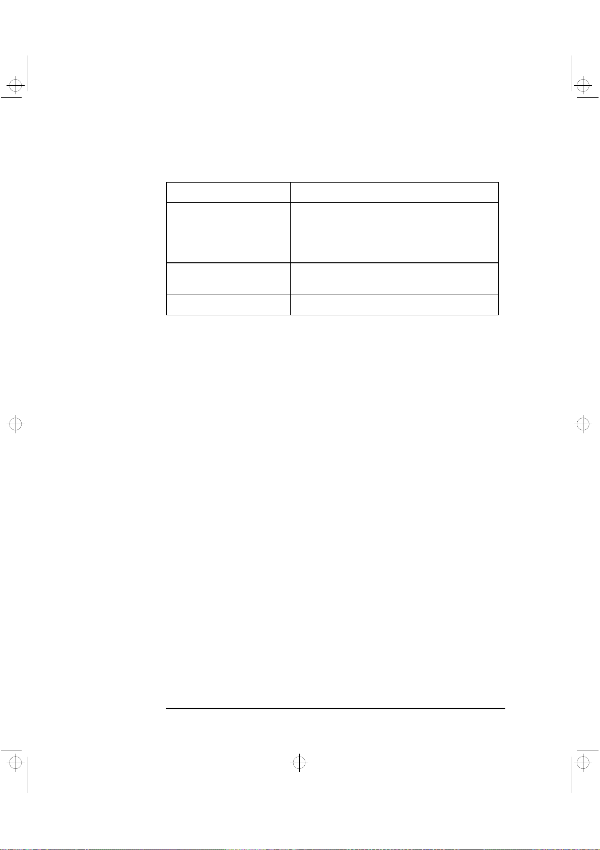
crystal.bk : cryst-4.fb4 Page 84 Monday, March 23, 1998 4:09 AM
4 Technical Information
Features
Feature: Description:
Keyboard/Mouse • HP enhanced keyboard with mini-DIN connector
XU Models: • HP enhanced scrolling mouse with mini-DIN connector
XW Models: • HP three-button mouse with mini-DIN connector
HP UltraFlow cooling system Cooling system with multiple temperature-regulated fans to
optimize cooling
Headset Stereo headset with microphone
84 English
 Loading...