

Page 1

xp8010 series
H
!
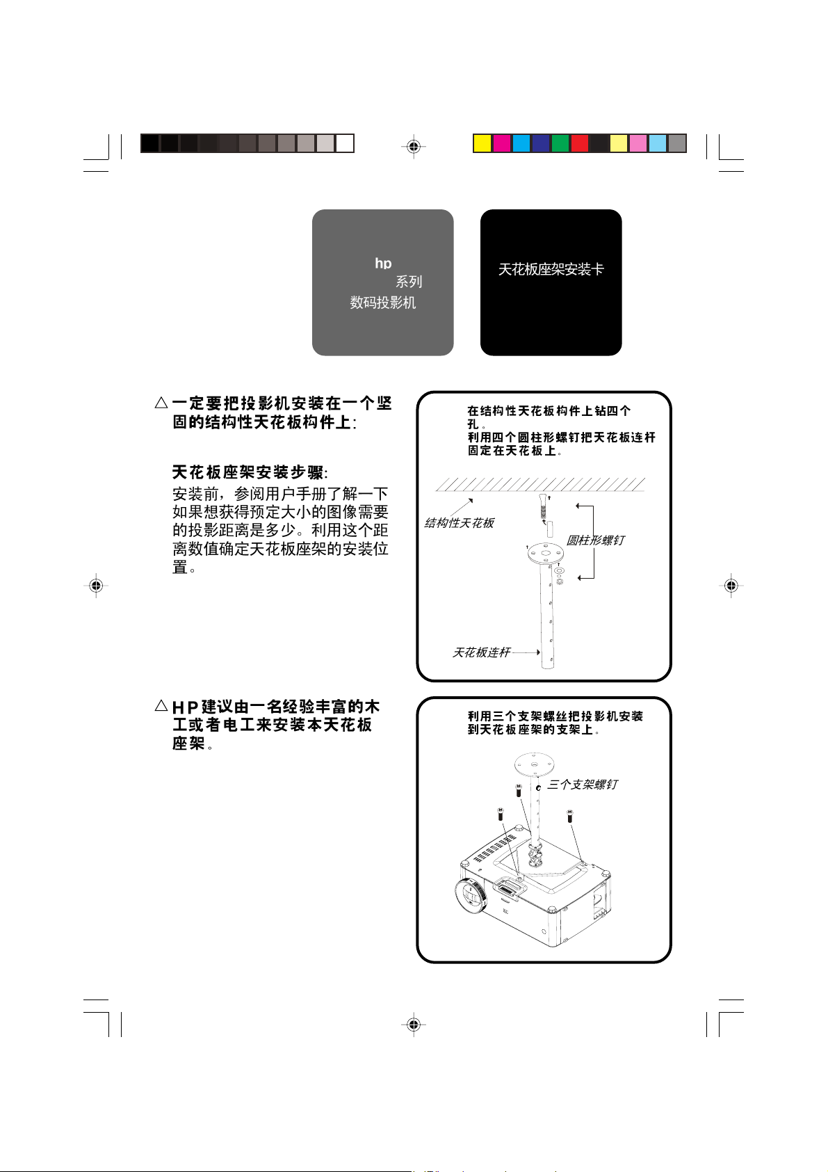
Be sure to install the projector
into a solid, structural ceiling
member:
Ceiling Mounting Procedure:
4
Before installation, refer to the
user manual for the projection
distance based upon the desired
image size. Use this projection
distance to locate the ceiling
mount.
digital projector
hp
u
Drill four holes into the structural ceiling
member.
Attach the ceiling rod to the ceiling with
the four cylinder screws.
Structural Ceiling
Ceiling Rod
Ceiling Mount
Installation Card
Cylinder Screw
!
HP recommends that a competent carpenter or electrician
install this ceiling mount.
Candela Ceiling Mount_En.p65 92/8/22, PM 04:301
v
Mount the projector to the ceiling mount
bracket with the three bracket screws.
Three Bracket Screws
Page 2

w
Attach the ceiling bracket to the ceiling rod with
the round thumbscrew. Height adjustments can
be made by using different holes on the ceiling
rod and ceiling bracket.
The total adjustment range is15.75 to 25.6
v v
v
v v
inches (40~65cm). Adjusments can be
made in one inch (2.5cm) increments.
Make necessary roll and yaw adjustments to the projector.
x
Round Thumbscrew
Ceiling Bracket
(YAW ADJUSTMENT)
Open the on-screen menu and select Setup > Projector Position. Select the
v v
v
v v
appropriate ceiling option.
C
Copyright Hewlett-Packard Company 2003
First Edition (August 2003)
Printed in Taiwan
Candela Ceiling Mount_En.p65 92/8/22, PM 04:302
(ROLL ADJUSTMENT)
180°
±60° ±20°
P/N 36.87108.001-A
Page 3

Série xp8010
H
!
Prenez soin d’installer le
projecteur numérique
projecteur dans un élément
plein de la structure du plafond:
4 Procédure de Montage au
Plafond:
Avant l’installation, reportez-vous
au manuel utilisateur pour la distance de projection en fonction de
la taille d’image désirée. Utilisez
cette distance de projection pour
repérer le montage au plafond.
hphp
hp
hphp
Carte d’Installation
pour Montage au
Plafond
X
Plafond avec structure
Percez quatre trous dans la structure
du renfort de plafond.
Fixez la tige de plafond au plafond à
l’aide des quatre vis de cylindre.
Tige de Plafond
Vis de Cylindre
!
HP recommande de faire
appel à un charpentier ou un
électricien compétant pour
installer ce montage de
plafond.
Candela Ceiling Mount-FRE.p65 2003/8/26, ¤W¤È 10:011
Y
Montez le projecteur sur le support
de montage de plafond à l’aide des
trois vis du support.
Trois Vis de Support
Page 4

Z
Fixez le support de plafond à la tige de
plafond avec les vis à oreilles rondes. Huit
réglages peuvent être réalisés en utilisant
différents trous sur la tige de plafond et le
support de plafond.
La plage de réglage totale est de 75 à 25.
6 pouces (40~65cm). Les réglages
peuvent être faits par incrémentation
d’un pouce (2.5cm).
Faites les réglages d’inclinaison et de direction nécessaires du projecteur.
[
Support de Plafond
Vis à oreilles ronde
(RÉGLAGE DE DIRECTION)
Ouvrez le menu d’affichage d’écran et sélectionnez
du Projecteurdu Projecteur
du Projecteur. Sélectionnez les options de plafond appropriées.
du Projecteurdu Projecteur
C
Copyright Hewlett-Packard Company, 2003
Première Edition (Août 2003)
Imprimé à Taïwan
Candela Ceiling Mount-FRE.p65 2003/8/26, ¤W¤È 10:012
180°
(RÉGLAGE D’INCLINAISON)
±60° ±20°
Régler Régler
Régler
Régler Régler
P/N 36.87108.001-A
tt
Position Position
t
Position
tt
Position Position
Page 5

Serie xp8010
H
!
Der Projektor muss an einem
Digitalprojektor
soliden Konstruktionselement
aus der Decke befestigt werden:
4 Vorgang für die
Deckenbefestigung:
Vor der Installation lesen Sie
das Benutzerhandbuch, um den
korrekten Projektionsabstand je
nach der gewünschten
Bildgröße zu ermitteln. Suchen
Sie anhand dieses Abstandes
den Befestigungspunkt an der
Decke aus.
hphp
hp
hphp
Installationskarte
für die
Deckenbefestigung
X
Bohren Sie vier Löcher in das
Konstruktionselement in der Decke.
Befestigen Sie die Deckenstange mit
Hilfe der vier mitgelieferten
Zylinderschrauben.
Konstruktionselement
in der Decke
Deckenstange
Zylinderschraube
!
HP empfiehlt, dass die
Installation des Projektors
von einem autorisierten
Zimmermann bzw. Elektriker
durchgeführt wird.
Candela Ceiling Mount-GER.p65 2003/8/26, ¤W¤È 10:031
Y
Befestigen Sie den Projektor an der
Deckenhalterung mit den drei
Befestigungsschrauben.
Drei
Befestigungsschrauben
Page 6

Z
Bohren Sie vier Löcher in das
Befestigen Sie die Deckenhalterung an die
Deckenstange mit der runden
Flügelschraube. Die Höhe kann man
verstellen, indem verschiedene Löcher der
Deckenstange bzw. der Deckenhalterung
benutzt werden.
Der gesamte Bereich für die
Höhenverstellung liegt zwischen
40~65cm. Die Verstellung erfolgt in 2,5
cm Schritte.
Positionieren Sie den Projektor wie gewünscht, durch kippen und schwenken.
[
Runde
Flügelschraube
Deckenhalterung
(VERSTELLUNG DURCH SCHWENKEN)
180°
Öffnen Sie das OSD-Menü und wählen Sie
(Projektorposition einstellen). Wählen Sie die entsprechende Option aus.
C
Copyright Hewlett-Packard Company 2003
Erste Auflage (August 2003)
Printed in Taiwan
Candela Ceiling Mount-GER.p65 2003/8/26, ¤W¤È 10:032
(VERSTELLUNG DURCH KIPPEN)
±60° ±20°
Setup Setup
Setup
Setup Setup
tt
Projector Position Projector Position
t
Projector Position
tt
Projector Position Projector Position
P/N 36.87108.001-A
Page 7

proiettore digitale
H
!
Accertarsi di installare il
serie xp8010
proiettore su un elemento del
soffitto solito e strutturale:
4 Procedura di montaggio a
soffitto:
Prima dell’installazione, fare
riferimento al manuale dell’utente
per la distanza di proiezione sulla
base delle dimensioni dell’immagine
desiderate. Utilizzare tale distanza
di proiezione per localizzare il
punto di montaggio a soffitto.
hphp
hp
hphp
X
Asta di sostegno
Praticare quattro fori con il trapano
nell’elemento strutturale del soffitto:
Fissare l’asta di sostegno al soffitto
utilizzando le quattro viti cilindriche.
Soffitto strutturale
Scheda di
montaggio a
soffitto
Vite cilindrica
!
HP consiglia che il
montaggio a soffitto venga
eseguito da un carpentiere
o elettricista competente.
Candela Ceiling Mount-ITA.p65 2003/8/26, ¤W¤È 10:041
Y
Montare il proiettore alla staffa di
montaggio a soffitto con le tre apposite viti.
Tre viti per la staffa
Page 8

Z
Fissare la staffa di montaggio a soffitto
all’asta di sostegno con le quattro viti a
testa zigrinata. È possibile eseguire
regolazioni in altezza utilizzando i differenti
fori sull’asta di sostegno e sulla staffa di
montaggio a soffitto.
La gamma di regolazione totale è da 40 a
65 cm. Le regolazioni possono essere
eseguite in incrementi da 2,5 cm.
Effettuare le opportune regolazioni allo snodo del proiettore.
[
Vite a testa zigrinata
tonda
Staffa di montaggio a soffitto
(REGOLAZIONE DI ROTAZIONE)
Aprire il menu a schermo e selezionare
proiettoreproiettore
proiettore. Selezionare l’opzione del soffitto appropriata.
proiettoreproiettore
C
Copyright Hewlett-Packard Company, 2003
Prima edizione (Agosto 2003)
Stampato a Taiwan
Candela Ceiling Mount-ITA.p65 2003/8/26, ¤W¤È 10:042
180°
(REGOLAZIONE DI INCLINAZIONE)
±60° ±20°
Configura Configura
Configura
Configura Configura
tt
Posizione del Posizione del
t
Posizione del
tt
Posizione del Posizione del
P/N 36.87108.001-A
Page 9

hphp
hp
hphp
serie xp8010
H
!
Asegúrese de instalar el
proyector digital
proyector en una parte sólida
de la estructura del techo:
4 Procedimiento de montaje en
el techo:
Antes de la instalación, consulte
el manual del usuario para la
distancia de proyección basada
en el tamaño de imagen
deseado. Utilice esta distancia de
proyección para la colocación del
montaje en el techo.
Tarjeta de
instalación para
montaje en el
techo
X
Haga cuatro agujeros en la estructura
del techo.
Asegure la varilla al techo con los
cuatro tornillos cilíndricos.
Estructura del techo
Varilla del techo
Tornillo cilíndrico
!
HP recomienda que sea un
carpintero o electricista
quien instale este montaje
en el techo.
Candela Ceiling Mount-SP.p65 2003/8/26, ¤W¤È 10:471
Y
Monte el proyector en el montaje del
techo con ayuda de los tres tornillos
de soporte.
Tres tornillos de soporte
Page 10

Z
Una el soporte del techo a la varilla del
techo con el tornillo tope redondo. Puede
realizar ajustes de altura usando distintos
agujeros en la varilla y en el soporte del
techo.
El alcance de ajuste total es de15.75 a
25.6 pulgadas (40~65cm). Puede realizar
los ajustes a incrementos de una
pulgada (2.5cm).
Haga los ajustes necesarios de giro e inclinación en el proyector.
[
Tornillo tope redondo
Soporte del techo
(AJUSTE DE GIRO)
Abra el menú en pantalla y seleccione
Seleccione la opción del techo apropiada.
C
Copyright Hewlett-Packard Company 2003
Primera edición (agosto de 2003)
Impreso en Taiwán
Candela Ceiling Mount-SP.p65 2003/8/26, ¤W¤È 10:472
180°
(AJUSTE DE INCLINACIÓN)
±60° ±20°
Configuracion Configuracion
Configuracion
Configuracion Configuracion
tt
t
tt
P/N 36.87108.001-A
Pos proyectorPos proyector
Pos proyector.
Pos proyectorPos proyector
Page 11

H
hp
xp8010
44
4
44
!
!
HP
:
:
X
Y
4
4
3
3
Candela Ceiling Mount-JP.p65 2003/8/21, ¤U¤È 04:291
Page 12

Z
(40~65cm) 1 (2.5cm)
15.75~25.6
[
)
180°
]
C
Copyright Hewlett-Packard Company 2003
(2003 8 )
Printed in Taiwan
Candela Ceiling Mount-JP.p65 2003/8/21, ¤U¤È 04:292
±60° ±20°
tt
t
[ ]
tt
[
P/N 36.87108.001-A
Page 13

H
xp8010
44
4
44
!
.
.
!
X
Y
Candela Ceiling Mount-KO.p65 2003/8/21, ¤U¤È 03:201
Page 14

Z
[
)
C
Copyright Hewlett-Packard Company 2003
(2003 8 )
:
Candela Ceiling Mount-KO.p65 2003/8/21, ¤U¤È 03:202
t .
.
180°
±60° ±20°
P/N 36.87108.001-A
Page 15

H
44
4
44
!
!
X
Y
Candela Ceiling Mount-TC.p65 2003/8/26, ¤W¤È 10:311
Page 16

Z
[
C
Candela Ceiling Mount-TC.p65 2003/8/26, ¤W¤È 10:312
Hewlett-Packard Company 2003
(2003 8 )
180°
±60° ±20°
P/N 36.87108.001-A
Page 17
H
xp8010
44
4
44
!
!
X
Y
Candela Ceiling Mount-SC.p65 2003/8/21, ¤U¤È 04:381
Page 18

Z
[
t
C
Hewlett-Packard 2003
2003 8
Candela Ceiling Mount-SC.p65 2003/8/21, ¤U¤È 04:382
180°
±60° ±20°
P/N 36.87108.001-A
Page 19

Candela Ceiling Mount_Cover.p65 92/8/22, AM 11:301
Page 20

Candela Ceiling Mount_Cover.p65 92/8/22, AM 11:302
36.87108.001-A
 Loading...