

Page 1

Hitachi Command Suite
Dynamic Link Manager
(for Windows®) User Guide
Document Organization
Product Version
Getting Help
Contents
MK-92DLM129-29
Page 2

© 2014 Hitachi, Ltd. All rights reserved.
No part of this publication may be reproduced or transmitted in any form or by any means,
electronic or mechanical, including photocopying and recording, or stored in a database or retrieval
system for any purpose without the express written permission of Hitachi, Ltd.
Hitachi, Ltd., reserves the right to make changes to this document at any time without notice and
assumes no responsibility for its use. This document contains the most current information available
at the time of publication. When new or revised information becomes available, this entire
document will be updated and distributed to all registered users.
Some of the features described in this document might not be currently available. Refer to the most
recent product announcement for information about feature and product availability, or contact
Hitachi Data Systems Corporation at
Notice: Hitachi, Ltd., products and services can be ordered only under the terms and conditions of
the applicable Hitachi Data Systems Corporation agreements. The use of Hitachi, Ltd., products is
governed by the terms of your agreements with Hitachi Data Systems Corporation.
Hitachi is a registered trademark of Hitachi, Ltd., in the United States and other countries. Hitachi
Data Systems is a registered trademark and service mark of Hitachi, Ltd., in the United States and
other countries.
Archivas, Essential NAS Platform, HiCommand, Hi-Track, ShadowImage, Tagmaserve, Tagmasoft,
Tagmasolve, Tagmastore, TrueCopy, Universal Star Network, and Universal Storage Platform are
registered trademarks of Hitachi Data Systems.
AIX, AS/400, DB2, Domino, DS6000, DS8000, Enterprise Storage Server, ESCON, FICON,
FlashCopy, IBM, Lotus, MVS, OS/390, RS/6000, S/390, System z9, System z10, Tivoli, VM/ESA,
z/OS, z9, z10, zSeries, z/VM, and z/VSE are registered trademarks or trademarks of International
Business Machines Corporation.
https://portal.hds.com.
All other trademarks, service marks, and company names in this document or web site are
properties of their respective owners.
Microsoft product screen shots are reprinted with permission from Microsoft Corporation.
Notice on Export Controls. The technical data and technology inherent in this Document may be
subject to U.S. export control laws, including the U.S. Export Administration Act and its associated
regulations, and may be subject to export or import regulations in other countries. Reader agrees to
comply strictly with all such regulations and acknowledges that Reader has the responsibility to
obtain licenses to export, re-export, or import the Document and any Compliant Products.
ii
Hitachi Dynamic Link Manager (for Windows®) User Guide
Page 3

Contents
Preface.................................................................................................. xi
Intended audience....................................................................................................xii
Product version........................................................................................................ xii
Release notes...........................................................................................................xii
Document revision level............................................................................................ xii
Document organization............................................................................................ xiii
Related documents.................................................................................................. xiii
Document conventions.............................................................................................xiv
Conventions for storage capacity values.................................................................... xiv
Accessing product documentation..............................................................................xv
Getting help.............................................................................................................xv
Comments.............................................................................................................. xvi
1 Overview of HDLM................................................................................1-1
What is HDLM?.......................................................................................................1-2
HDLM Features.......................................................................................................1-2
2 HDLM Functions................................................................................... 2-1
Devices Managed by HDLM......................................................................................2-3
System Configuration.............................................................................................. 2-3
System Configuration Using an FC-SAN.............................................................. 2-3
System Configuration Using an IP-SAN...............................................................2-5
Setting Range of the iSCSI Software and iSCSI HBA...................................2-7
Storage systems Supported by HDLM....................................................... 2-7
LU Configuration.....................................................................................................2-7
Program Configuration............................................................................................ 2-9
Driver Levels of the HDLM and MPIO Drivers...........................................................2-10
Distributing a Load Using Load Balancing................................................................2-11
Paths to Which Load Balancing Is Applied.........................................................2-13
When Using the Thunder 9500V Series, or Hitachi AMS/WMS Series..........2-13
When Using Other Than the Thunder 9500V Series and Hitachi AMS/WMS
Series................................................................................................... 2-14
Load Balancing Algorithms...............................................................................2-15
Performing Failovers and Failbacks Using Path Switching......................................... 2-17
Automatic Path Switching................................................................................ 2-17
Hitachi Dynamic Link Manager (for Windows®) User Guide
iii
Page 4

Automatic Failovers............................................................................... 2-17
Automatic Failbacks...............................................................................2-19
Manual Path Switching.................................................................................... 2-19
Path Status Transition..................................................................................... 2-20
The Online Path Statuses....................................................................... 2-21
The Offline Path Statuses.......................................................................2-22
Status Transitions of a Path....................................................................2-22
Monitoring Intermittent Errors (Functionality When Automatic Failback Is Used)........2-26
Checking Intermittent Errors............................................................................2-26
Setting Up Intermittent Error Monitoring...........................................................2-26
Intermittent Error Monitoring Actions............................................................... 2-27
When an Intermittent Error Occurs......................................................... 2-27
When an Intermittent Error Does Not Occur............................................ 2-28
When the Conditions for an Intermittent Error Are Changed During Error
Monitoring............................................................................................ 2-28
When a User Changes the Intermittent Error Information.................................. 2-29
Detecting Errors by Using Path Health Checking...................................................... 2-31
Distributing a Load by Using the Dynamic I/O Path Control Function.........................2-32
What is the Dynamic Load Balance Control Function..........................................2-32
Dynamic I/O Path Control Function.................................................................. 2-32
Dynamic Re-configuration......................................................................................2-33
Adding an LU Dynamically............................................................................... 2-33
Deleting an LU Dynamically............................................................................. 2-33
Error Management................................................................................................ 2-33
Types of Collected Logs...................................................................................2-34
Filtering of Error Information........................................................................... 2-36
Collecting Error Information Using the Utility for Collecting HDLM Error Information
(DLMgetras)................................................................................................... 2-37
Collecting Audit Log Data.......................................................................................2-37
Categories and Audit Events that HDLM Can Output to the Audit Log................. 2-39
Requirements for Outputting Audit Log Data.....................................................2-43
Destination and Filtering of Audit Log Data....................................................... 2-43
Audit Log Data Formats...................................................................................2-44
Integrated HDLM management using Global Link Manager.......................................2-45
Cluster Support.....................................................................................................2-46
3 Creating an HDLM Environment............................................................. 3-1
HDLM System Requirements....................................................................................3-2
OSs Supported by HDLM................................................................................... 3-2
Supported OSs........................................................................................3-2
Microsoft MPIO Drivers............................................................................ 3-3
Web Browsers Supported by HDLM.......................................................... 3-3
Storage systems Supported by HDLM.................................................................3-3
Supported Storage systems......................................................................3-3
HBAs......................................................................................................3-6
When Using Intermediate Volumes Managed by Hitachi RapidXchange to
Exchange Data........................................................................................3-6
Cluster Software Supported by HDLM.................................................................3-7
Volume Managers Supported by HDLM.............................................................3-12
Virtual Environments Supported by HDLM.........................................................3-12
Memory and Disk Capacity Requirements......................................................... 3-13
Memory Requirements...........................................................................3-13
iv
Hitachi Dynamic Link Manager (for Windows®) User Guide
Page 5

Disk Requirements.................................................................................3-13
Number of LUs and Paths That Are Supported in HDLM..................................... 3-14
Flow for Creating an HDLM Environment.................................................................3-14
HDLM Installation Types........................................................................................3-14
Notes on Creating an HDLM Environment............................................................... 3-15
Notes on HBAs and HBA Drivers.......................................................................3-15
Notes on Storage systems............................................................................... 3-15
Notes on HDLM Versions................................................................................. 3-16
Notes on Windows..........................................................................................3-17
Notes on Related Software.............................................................................. 3-20
Notes on New Installations and Upgrade Installations........................................3-23
Notes on Migration or Upgrade Installation....................................................... 3-25
Installing HDLM.................................................................................................... 3-26
Preparations for a New Installation of HDLM.....................................................3-26
Preparations for Installing HDLM by Performing an Unattended Installation.........3-28
How to Create an Installation-Information Settings File............................ 3-28
Notes on an Unattended Installation....................................................... 3-29
Performing a New Installation of HDLM on Windows Server 2003.......................3-29
In a Non-Cluster Environment................................................................ 3-29
When MSCS Is Used.............................................................................. 3-34
When VCS Is Used.................................................................................3-43
When Oracle RAC Is Used...................................................................... 3-47
Performing a New Installation of HDLM on Windows Server 2008 and Windows
Server 2012....................................................................................................3-52
In a Non-Cluster Environment................................................................ 3-52
When MSCS Is Used.............................................................................. 3-56
Upgrade Installation or Re-installation of HDLM................................................ 3-64
Migrating from HDLM 5.4 or Earlier to HDLM 5.5 or Later.................................. 3-66
Installing JRE................................................................................................. 3-67
Firewall Settings for Managing HDLM by Using Global Link Manager................... 3-68
firewall_setup command syntax..............................................................3-69
Checking the Path Configuration............................................................................ 3-70
Setting Up HDLM.................................................................................................. 3-71
Checking the Current Settings..........................................................................3-71
Setting Up the HDLM Functions........................................................................3-72
Setting Up Load Balancing..................................................................... 3-73
Setting Up Path Health Checking............................................................ 3-74
Setting Up the Automatic Failback Function.............................................3-74
Setting Up Intermittent Error Monitoring................................................. 3-75
Setting Up Dynamic I/O Path Control...................................................... 3-75
Setting Up the LU Deletion Function....................................................... 3-76
Setting the Error Log Collection Level......................................................3-77
Setting the Trace Level.......................................................................... 3-77
Setting the Error Log File Size................................................................ 3-78
Setting the Number of Error Log Files..................................................... 3-79
Setting the Trace File Size......................................................................3-79
Setting the Number of Trace Files...........................................................3-79
Setting Up Audit Log Data Collection.......................................................3-80
Checking the Updated Settings........................................................................ 3-81
Setting Up Integrated Traces................................................................................. 3-81
Removing HDLM................................................................................................... 3-84
Preparations for HDLM Removal.......................................................................3-84
Hitachi Dynamic Link Manager (for Windows®) User Guide
v
Page 6

Notes on Removing HDLM...............................................................................3-84
Removing HDLM.............................................................................................3-86
Removal Procedures - in a Non-Cluster Environment................................3-86
Removal Procedures - MSCS or VCS Environment.................................... 3-88
Removal Procedures - Oracle RAC Environment....................................... 3-90
Removing Hitachi Network Objectplaza Trace Library (HNTRLib2)...................... 3-91
Clearing the Persistent Reservation.................................................................. 3-93
4 HDLM Operation................................................................................... 4-1
Notes on Using HDLM............................................................................................. 4-2
Using a Storage Management Program...............................................................4-2
Upgrading Windows..........................................................................................4-2
Using MSCS......................................................................................................4-2
When the Number of Displayed Paths Is Less than the Actual Number of Paths
..............................................................................................................4-2
When a System Event Occurs in an MSCS Environment..............................4-2
Using the EMC DMX series, EMC CX series, and HP EVA series............................. 4-2
Using Symantec Backup Exec for Windows and the Veritas NetBackup Intelligent
Disaster Recovery Function............................................................................... 4-3
Using Windows Server 2008 or Windows Server 2012......................................... 4-3
HDLM Operations Using the HDLM GUI.....................................................................4-4
Notes on Using the HDLM GUI...........................................................................4-4
Viewing the GUI Help........................................................................................4-4
Using Commands for HDLM Operations.................................................................... 4-4
Notes on Using Commands................................................................................4-4
Viewing Path Information..................................................................................4-5
Changing the Status of Paths.............................................................................4-5
Changing the Status of Paths to Online.....................................................4-6
Changing the Status of Paths to Offline(C)................................................ 4-6
Viewing LU Information.....................................................................................4-7
Initializing Statistical Information for Paths.........................................................4-8
Viewing and Setting Up the Operating Environment............................................ 4-8
Viewing the Operating Environment..........................................................4-8
Setting Up the Operating Environment......................................................4-9
Viewing License Information............................................................................4-10
Updating the License.......................................................................................4-10
Viewing HDLM Version Information.................................................................. 4-11
Viewing HDLM Component Information............................................................ 4-12
Using the Windows Administrative Tool (Performance) to Check Path Information..... 4-13
Starting and Stopping the HDLM Manager...............................................................4-14
Starting the HDLM Manager.............................................................................4-15
Stopping the HDLM Manager........................................................................... 4-15
HDLM Resident Processes......................................................................................4-16
Reconfiguring the HDLM Operating Environment..................................................... 4-16
Setting Up an Added LU and Path as an HDLM Management-target....................4-16
Setting Up an Added LU as an HDLM Management-target........................ 4-16
Checking an Added Path........................................................................ 4-18
Deleting an LU Dynamically............................................................................. 4-19
Requirements to Delete the LU Dynamically............................................ 4-19
Checking that the LU or Path Has Been Dynamically Deleted.................... 4-19
Recovering a Deleted LU or Path............................................................ 4-21
vi
Hitachi Dynamic Link Manager (for Windows®) User Guide
Page 7

5 Troubleshooting....................................................................................5-1
Information Collected by the DLMgetras Utility for Collecting HDLM Error Information. 5-2
Checking Error Information in Messages...................................................................5-2
What To Do for a Path Error.................................................................................... 5-4
Examining the Messages................................................................................... 5-5
Obtaining Path Information............................................................................... 5-5
Identifying the Error Path..................................................................................5-6
Narrowing Down the Hardware That Might Have Caused the Error....................... 5-6
Identifying the Error Location and Correcting any Hardware Errors.......................5-6
Placing the Path Online..................................................................................... 5-6
What To Do for a Program Error.............................................................................. 5-6
Examining the Messages................................................................................... 5-7
Obtaining Program Information......................................................................... 5-7
What To Do for the Program Error..................................................................... 5-7
Contacting your HDLM Vendor or Maintenance Company.....................................5-8
What To Do for Other Errors....................................................................................5-8
6 Command Reference.............................................................................6-1
Overview of the HDLM Command dlnkmgr................................................................6-2
clear (Returns the Path Statistics to the Initial Value)................................................ 6-3
Format.............................................................................................................6-3
To Set the Path Statistics to 0.................................................................. 6-3
To Display the Format of the clear Operation............................................ 6-3
Parameters...................................................................................................... 6-3
To Set the Path Statistics to 0.................................................................. 6-3
To Display the Format of the clear Operation............................................ 6-4
help (Displays the Operation Format)....................................................................... 6-4
Format.............................................................................................................6-4
Parameter........................................................................................................6-4
offline (Places Paths Offline)....................................................................................6-6
Format.............................................................................................................6-6
To Place Paths Offline..............................................................................6-6
To Display the Format of the offline Operation.......................................... 6-6
Parameters...................................................................................................... 6-6
To Place Paths Offline..............................................................................6-6
To Display the Format of the Offline Operation..........................................6-9
online (Places Paths Online)...................................................................................6-11
Format...........................................................................................................6-11
To Place Paths Online............................................................................ 6-11
To Display the Format of the Online Operation........................................ 6-11
Parameters.....................................................................................................6-11
To Place Paths Online............................................................................ 6-11
To Display the Format of the Online Operation........................................ 6-14
set (Sets Up the Operating Environment)................................................................6-16
Format...........................................................................................................6-16
To Set Up the HDLM Operating Environment........................................... 6-16
To Display the Format of the Set Operation.............................................6-16
Parameters.....................................................................................................6-16
To Set Up the HDLM Operating Environment........................................... 6-16
To Display the Format of the Set Operation.............................................6-31
view (Displays Information)................................................................................... 6-33
Format...........................................................................................................6-33
Hitachi Dynamic Link Manager (for Windows®) User Guide
vii
Page 8

To Display Program Information............................................................. 6-33
To Display HDLM Management-target Device Information........................ 6-33
To Display Path Information...................................................................6-33
To Display LU Information......................................................................6-34
To Display the Format of the view Operation...........................................6-34
Parameters.....................................................................................................6-35
Parameters Used When Displaying Program Information.......................... 6-35
Parameters Used When Displaying HDLM Management-target Device
Information...........................................................................................6-42
Parameters Used When Displaying Path Information................................ 6-43
Parameters Used When Displaying LU Information...................................6-60
Parameter Used When Displaying the Format of the view Operation..........6-76
delete (Deletes a Path Dynamically)....................................................................... 6-77
Format...........................................................................................................6-77
To Delete a Path Dynamically.................................................................6-77
To Display the Format of the delete Operation.........................................6-77
Parameters.....................................................................................................6-77
To Delete a Path Dynamically.................................................................6-77
To Display the Format of the delete Operation.........................................6-78
7 Utility Reference................................................................................... 7-1
Overview of the Utilities.......................................................................................... 7-2
The DLMgetras Utility for Collecting HDLM Error Information......................................7-2
Format.............................................................................................................7-3
When Executing the DLMgetras Utility from the Command Prompt..............7-3
When Executing the DLMgetras Utility from the Windows Start Menu..........7-3
Parameters...................................................................................................... 7-3
List of Collected Error Information..................................................................... 7-4
The dlmpr Utility for Clearing HDLM Persistent Reservations.....................................7-10
Format...........................................................................................................7-10
Parameters.....................................................................................................7-10
Procedure for Executing the dlmpr Utility in MSCS Environments:............. 7-11
Procedure for Executing the dlmpr Utility in VCS Environments:................7-12
The dlmprsvkey Utility for Registering an HDLM Persistent Reservation Key...............7-13
Format...........................................................................................................7-13
Parameter...................................................................................................... 7-13
The dlmchkpath Utility for Checking HDLM Paths.....................................................7-14
Format...........................................................................................................7-14
Parameters.....................................................................................................7-14
The dlmhostinfo Utility for Checking HDLM Installation Information.......................... 7-16
Format...........................................................................................................7-16
Parameters.....................................................................................................7-16
The installhdlm Utility for Installing HDLM...............................................................7-17
Format...........................................................................................................7-18
Parameters.....................................................................................................7-18
Contents of an Installation-Information Settings File..........................................7-18
About the Log File...........................................................................................7-27
The removehdlm Utility for Removing HDLM........................................................... 7-28
Format...........................................................................................................7-28
Parameters.....................................................................................................7-28
viii
Hitachi Dynamic Link Manager (for Windows®) User Guide
Page 9

8 Messages............................................................................................. 8-1
Before Viewing the List of Messages.........................................................................8-3
Format and Meaning of Message IDs................................................................. 8-3
Terms Used in Messages and Message Explanations............................................8-3
KAPL01001 to KAPL02000....................................................................................... 8-4
KAPL02001 to KAPL03000......................................................................................8-30
KAPL03001 to KAPL04000......................................................................................8-44
KAPL04001 to KAPL05000......................................................................................8-46
KAPL05001 to KAPL06000......................................................................................8-54
KAPL07001 to KAPL08000......................................................................................8-58
KAPL08001 to KAPL09000......................................................................................8-60
KAPL09001 to KAPL10000......................................................................................8-64
KAPL10001 to KAPL11000......................................................................................8-87
KAPL11001 to KAPL12000......................................................................................8-95
KAPL12001 to KAPL13000......................................................................................8-98
KAPL13001 to KAPL14000....................................................................................8-106
KAPL15001 to KAPL16000....................................................................................8-109
Return Codes for Hitachi Command Suite Common Agent Component.....................8-112
Events Output to Windows Event Logs by HDLM....................................................8-117
A Functional Differences Between Versions of HDLM.................................. A-1
Functional Differences Between Version 6.6 or Later and Versions Earlier Than 6.6..... A-3
Functional Differences Between Version 6.2 or Later and Versions Earlier Than 6.2..... A-3
Functional Differences Between Version 6.0.1 or Later and Versions Earlier Than 6.0.1
.............................................................................................................................A-3
Functional Differences Between Version 6.0 or Later and Versions Earlier Than 6.0..... A-3
Functional Differences Between Version 5.9.4 or Later and Versions Earlier Than 5.9.4
.............................................................................................................................A-4
Functional Differences Between Version 5.9.1 or Later and Versions Earlier Than 5.9.1
.............................................................................................................................A-4
Functional Differences Between Versions 5.9 or Later and Versions Earlier Than 5.9....A-4
Path Status Transition and Automatic Path Switching................................................ A-4
Status Transition of Paths in the Online Status....................................................A-4
Automatic Switching of Paths That Have the Online(E), Offline(C), or Offline(E)
Status..............................................................................................................A-5
Differences in the LU Dynamic Removal Function......................................................A-6
Differences in the Drive Letters Displayed in Windows...............................................A-7
Differences in Default Values...................................................................................A-7
Differences in the Load Balancing Function in an MSCS Environment..........................A-7
Acronyms and abbreviations
Glossary
Index
Hitachi Dynamic Link Manager (for Windows®) User Guide
ix
Page 10

x
Hitachi Dynamic Link Manager (for Windows®) User Guide
Page 11

Preface
This document describes how to use the Hitachi Dynamic Link Manager.
Intended audience
□
Product version
□
Release notes
□
Document revision level
□
Document organization
□
Related documents
□
Document conventions
□
Conventions for storage capacity values
□
Accessing product documentation
□
Getting help
□
Comments
□
Hitachi Dynamic Link Manager (for Windows®) User Guide
Preface
xi
Page 12

Intended audience
This document is intended for storage administrators who use Hitachi
Dynamic Link Manager (HDLM) to operate and manage storage systems, and
assumes that readers have:
• Knowledge of Windows and its management functionality
• Knowledge of Storage system management functionality
• Knowledge of Cluster software functionality
• Knowledge of Volume management software functionality
Product version
This document revision applies to HDLM for Windows version 8.0.0 or later.
Release notes
Read the release notes before installing and using this product. They may
contain requirements or restrictions that are not fully described in this
document or updates or corrections to this document.
Document revision level
Revision Date Description
MK-92DLM129-21 November 2011 Initial Release
MK-92DLM129-22 February 2012 Revision 1, supersedes and replaces
MK-92DLM129-23 July 2012 Revision 2, supersedes and replaces
MK-92DLM129-24 August 2012 Revision 3, supersedes and replaces
MK-92DLM129-25 November 2012 Revision 4, supersedes and replaces
MK-92DLM129-26 February 2013 Revision 5, supersedes and replaces
MK-92DLM129-27 May 2013 Revision 6, supersedes and replaces
MK-92DLM129-28 October 2013 Revision 7, supersedes and replaces
MK-92DLM129-29 April 2014 Revision 8, supersedes and replaces
MK-92DLM129-21
MK-92DLM129-22
MK-92DLM129-23
MK-92DLM129-24
MK-92DLM129-25
MK-92DLM129-26
MK-92DLM129-27
MK-92DLM129-28
xii
Preface
Hitachi Dynamic Link Manager (for Windows®) User Guide
Page 13
Document organization
The following table provides an overview of the contents and organization of
this document. Click the chapter title in the left column to go to that chapter.
The first page of each chapter provides links to the sections in that chapter.
Chapter/Appendix Description
Chapter 1, Overview of HDLM on
page 1-1
Chapter 2, HDLM Functions on
page 2-1
Chapter 3, Creating an HDLM
Environment on page 3-1
Chapter 4, HDLM Operation on
page 4-1
Chapter 5, Troubleshooting on
page 5-1
Chapter 6, Command Reference
on page 6-1
Chapter 7, Utility Reference on
page 7-1
Describes an overview of HDLM, and its features.
Describes the system configuration of HDLM, and the
basic terms and functions for HDLM.
Describes the necessary preparations for installing
HDLM, and then describes how to install HDLM and set
up the various functions.
Describes how to use HDLM by using both the HDLM
GUI and commands, and how to manually start and
stop the HDLM manager. This chapter also describes
how to configure an environment to properly operate
HDLM, such as changing the HDLM managementtarget devices that connect paths or replacing the
hardware that makes up a path. Chapter 4 also
describes how to check path information by using the
Windows management tool.
Describes how to troubleshoot a path error, HDLM
failure, or any other problems that you might
encounter.
Describes all the HDLM commands.
Describes the HDLM utilities.
Chapter 8, Messages on page
8-1
Appendix A, Functional
Differences Between Versions of
HDLM on page A-1
Related documents
The following related Hitachi Command Suite documents are available on the
documentation CD:
• Hitachi Command Suite Global Link Manager Installation and
Configuration Guide, MK-95HC107
• Hitachi Command Suite Global Link Manager Messages, MK-95HC108
• Hitachi Adaptable Modular Storage 500 User and Reference Guide
• Hitachi Simple Modular Storage Series User's Guide
• Hitachi Unified Storage Series User's Guide
Describes information for all the possible messages
that could be output by HDLM. The chapter also
explains what to do in response to each message.
Describes the differences between HDLM versions.
Preface
Hitachi Dynamic Link Manager (for Windows®) User Guide
xiii
Page 14

• Hitachi USP Series User's Guide
• Hitachi Workgroup Modular Storage Series User's Guide
• Thunder9580V Series Disk Array Subsystem User's Guide
• Reference Manual / File Conversion Utility & File Access Library
• Universal Storage Platform V User's Guide
• Universal Storage Platform VM User's Guide
• Virtual Storage Platform User's Guide
Document conventions
This document uses the following typographic conventions:
Convention Description
Bold Indicates text on a window, other than the window title, including
menus, menu options, buttons, fields, and labels. Example: Click OK.
Italic Indicates a variable, which is a placeholder for actual text provided by
the user or system. Example: copy source-file target-file
Note: Angled brackets (< >) are also used to indicate variables.
Monospace
< > angled
brackets
[ ] square
brackets
{ } braces Indicates required or expected values. Example: { a | b } indicates
| vertical bar Indicates that you have a choice between two or more options or
underline
PROMPT>
Indicates text that is displayed on screen or entered by the user.
Example: # pairdisplay -g oradb
Indicates a variable, which is a placeholder for actual text provided by
the user or system. Example: # pairdisplay -g <group>
Note: Italic font is also used to indicate variables.
Indicates optional values. Example: [ a | b ] indicates that you can
choose a, b, or nothing.
that you must choose either a or b.
arguments. Examples: [ a | b ] indicates that you can choose a, b, or
nothing. { a | b } indicates that you must choose either a or b.
Indicates the default value.
Example:
[ a | b ]
Indicates the prompt in the window where the command is executed.
PROMPT indicates the current directory path displayed in the window.
Conventions for storage capacity values
xiv
Physical storage capacity values (for example, disk drive capacity) are
calculated based on the following values:
Preface
Hitachi Dynamic Link Manager (for Windows®) User Guide
Page 15
Physical capacity unit Value
1 kilobyte (KB)
1 megabyte (MB)
1 gigabyte (GB)
1 terabyte (TB)
1 petabyte (PB)
1 exabyte (EB)
1,000 (103) bytes
1,000 KB or 1,0002 bytes
1,000 MB or 1,0003 bytes
1,000 GB or 1,0004 bytes
1,000 TB or 1,0005 bytes
1,000 PB or 1,0006 bytes
Logical storage capacity values (for example, logical device capacity) are
calculated based on the following values:
Logical capacity unit Value
1 block 512 bytes
1 KB
1 MB
1 GB
1 TB
1 PB
1,024 (210) bytes
1,024 KB or 1,0242 bytes
1,024 MB or 1,0243 bytes
1,024 GB or 1,0244 bytes
1,024 TB or 1,0245 bytes
1 EB
Accessing product documentation
The HDLM user documentation is available on the Hitachi Data Systems
Portal: https://portal.hds.com. Check this site for the most current
documentation, including important updates that may have been made after
the release of the product.
Getting help
Hitachi Data Systems Support Portal is the destination for technical support of
your current or previously-sold storage systems, midrange and enterprise
servers, and combined solution offerings. The Hitachi Data Systems customer
support staff is available 24 hours a day, seven days a week. If you need
technical support, log on to the Hitachi Data Systems Support Portal for
contact information:
Hitachi Data Systems Community is a new global online community for HDS
customers, partners, independent software vendors, employees, and
prospects. It is an open discussion among these groups about the HDS
portfolio of products and services. It is the destination to get answers,
discover insights, and make connections. The HDS Community complements
https://portal.hds.com.
1,024 PB or 1,0246 bytes
Preface
Hitachi Dynamic Link Manager (for Windows®) User Guide
xv
Page 16

our existing Support Portal and support services by providing an area where
you can get answers to non-critical issues and questions. Join the
conversation today! Go to community.hds.com, register, and complete
your profile.
Comments
Please send us your comments on this document: doc.comments@hds.com.
Include the document title and number, including the revision level (for
example, -07), and refer to specific sections and paragraphs whenever
possible. All comments become the property of Hitachi Data Systems
Corporation.
Thank you!
xvi
Preface
Hitachi Dynamic Link Manager (for Windows®) User Guide
Page 17

1
Overview of HDLM
HDLM is a software package that manages paths between a host and a
storage system. HDLM is designed to distribute loads across multiple paths
and will switch a given load to another path if there is a failure in the path
that is currently being used, thus improving system reliability.
This chapter gives an overview of HDLM and describes its features.
What is HDLM?
□
HDLM Features
□
Overview of HDLM
Hitachi Dynamic Link Manager (for Windows®) User Guide
1-1
Page 18
What is HDLM?
With the widespread use of data warehousing and increasing use of
multimedia data, the need for high-speed processing of large volumes of data
on networks has rapidly grown. To satisfy this need, networks dedicated to
the transfer of data, such as SANs, are now being used to provide access to
storage systems.
HDLM manages the access paths to these storage systems. HDLM provides
the ability to distribute loads across multiple paths and switch to another path
if there is a failure in the path that is currently being used, thus improving
system availability and reliability.
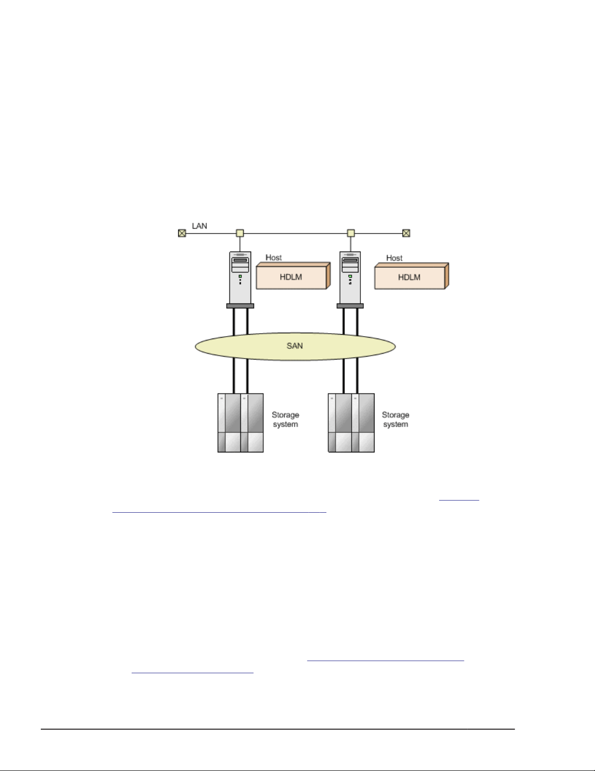
The figure below shows the connections between hosts and storage systems.
A server on which HDLM is installed is called a host.
Figure 1-1 Connections Between Hosts and Storage systems
For details about the storage systems supported by HDLM, see Storage
systems Supported by HDLM on page 3-3.
HDLM Features
HDLM features include the following:
The ability to distribute a load across multiple paths. This is also known as
load balancing.
When a host is connected to a storage system via multiple paths, HDLM
can distribute the load across all the paths. This prevents one, loaded
down path from affecting the processing speed of the entire system.
For details on load balancing, see
Balancing on page 2-11.
1-2
Hitachi Dynamic Link Manager (for Windows®) User Guide
Distributing a Load Using Load
Overview of HDLM
Page 19

The ability to continue running operations between a host and storage
system, even if there is a failure. This is also known as performing a failover.
When a host is connected to a storage system via multiple paths, HDLM
can automatically switch to another path if there is some sort of failure in
the path that is currently being used. This allows operations to continue
between a host and a storage system.
For details on performing failovers, see
Using Path Switching on page 2-17.
The ability to bring a path that has recovered from an error back online. This
is also known as performing a failback.
If a path is recovered from an error, HDLM can bring that path back
online. This enables the maximum possible number of paths to always be
available and online, which in turn enables HDLM to better distribute the
load across multiple paths.
Failbacks can be performed manually or automatically. In an automatic
failback, HDLM will automatically restore the path to an active state after
the user has corrected the problem that exists on the physical path.
For details on performing failbacks, see
Failbacks Using Path Switching on page 2-17.
The ability to automatically check the status of any given path at regular
intervals. This is also known as path health checking.
HDLM can easily detect errors by checking the statuses of paths at userdefined time intervals. This allows you to check for any existing path
errors and to resolve them promptly and efficiently.
For details on setting up and performing path health checking, see
Detecting Errors by Using Path Health Checking on page 2-31.
Performing Failovers and Failbacks
Performing Failovers and
A GUI, which allows you to operate HDLM in a visually pleasing and easy to
navigate environment. This is also known as the HDLM GUI.
HDLM can utilize both configuration-diagrams and the list format to
display information about all the paths that exist between hosts and
Hitachi storage systems. You can use the GUI to easily change the status
of any given path, and to set up a proper operating environment.
For details on the HDLM GUI, see the HDLM GUI Help.
Overview of HDLM
Hitachi Dynamic Link Manager (for Windows®) User Guide
1-3
Page 20

1-4
Overview of HDLM
Hitachi Dynamic Link Manager (for Windows®) User Guide
Page 21

2
HDLM Functions
This chapter describes the various functions that are built into HDLM. Before
the function specifications are explained though, this chapter will go into
detail about the HDLM management targets, system configuration, and basic
terms that are necessary to know to effectively operate HDLM. After that, the
rest of the chapter focuses on describing all the HDLM functions, including the
main ones: load distribution across paths and path switching.
Devices Managed by HDLM
□
System Configuration
□
LU Configuration
□
Program Configuration
□
Driver Levels of the HDLM and MPIO Drivers
□
Distributing a Load Using Load Balancing
□
Performing Failovers and Failbacks Using Path Switching
□
Monitoring Intermittent Errors (Functionality When Automatic Failback Is
□
Used)
Detecting Errors by Using Path Health Checking
□
Distributing a Load by Using the Dynamic I/O Path Control Function
□
Dynamic Re-configuration
□
Error Management
□
HDLM Functions
Hitachi Dynamic Link Manager (for Windows®) User Guide
2-1
Page 22

Collecting Audit Log Data
□
Integrated HDLM management using Global Link Manager
□
Cluster Support
□
2-2
HDLM Functions
Hitachi Dynamic Link Manager (for Windows®) User Guide
Page 23

Devices Managed by HDLM
Below is a list of devices that can or cannot be managed by HDLM. The
devices that can be managed by HDLM are called HDLM management-target
devices.
HDLM management-target devices:
The following devices are from the storage systems listed in Section What
is HDLM? on page 1-2:
¢
SCSI devices
¢
Hitachi storage system command devices, such as Hitachi RAID
Manager command devices
¢
The EMC DMX series, EMC CX series, and HP EVA series
Note that only the OSs below can be used to manage these devices.
For the EMC DMX series, EMC CX series, and HP EVA series:
- Windows Server 2003 (x86) SP1 or later
- Windows Server 2003 (IPF) SP1 or later
- Windows Server 2003 (x64)
For the EMC CX series:
- Windows Server 2008 can also be used.
For the HP EVA series:
- Windows Server 2008 R2 can also be used.
Non-HDLM management-target devices:
¢
SCSI devices other than those that are in the storage systems listed
in Section
¢
Built-in disks on a host
¢
Non-disk devices (tape devices, etc.)
What is HDLM? on page 1-2
System Configuration
HDLM is available in two SAN environment types: FC-SAN and IP-SAN. Note
that the EMC DMX series, EMC CX series, and HP EVA series can only be used
in an FC-SAN environment.
System Configuration Using an FC-SAN
In an FC-SAN, fiber cables connect hosts to storage systems. The cable port
on the host is called a host bus adapter (HBA). The cable port on the storage
system is called a port (P) on a channel adapter (CHA).
A logical unit (LU), which lies in a storage system, is either an input target or
an output target to or from a host. The areas within an LU are called Devs.
A route that connects a host to a Dev in an LU is called a path.
HDLM Functions
Hitachi Dynamic Link Manager (for Windows®) User Guide
2-3
Page 24

HDLM assigns a unique ID to each management-target path. This ID is called
AutoPATH_ID. Sometimes, the path is also just simply called a management
target.
The following figure shows the configuration of an HDLM system using an FCSAN.
Figure 2-1 Configuration of an HDLM System When Using an FC-SAN
The following table lists the HDLM system components when using an FCSAN.
Table 2-1 HDLM System Components When Using an FC-SAN
Components Description
HBA A host bus adapter. This serves as a cable port on the
host.
FC-SAN A dedicated network that is used for the transfer of
data between hosts and storage systems
CHA A channel adapter
P A port on a CHA. This serves as a cable port on a
storage system.
LU A logical unit with which a host can perform I/O
operations. This unit can be accessed from the network.
Dev A logical area (a partition) in an LU
Path A route that connects a host to a Dev in an LU
2-4
HDLM Functions
Hitachi Dynamic Link Manager (for Windows®) User Guide
Page 25
System Configuration Using an IP-SAN
In an IP-SAN, LAN cables are used to connect hosts to storage systems. The
cable port on the host is called an iSCSI host bus adapter (iSCSI HBA) or a
network interface card (NIC). In order to use an NIC, the iSCSI software
must be installed ahead of time on the host. The cable port on the storage
system is called a port (P) on a channel adapter (CHA) used for iSCSI
connections.
A logical unit (LU), which lies in a storage system, is either an input target or
an output target to or from a host. The areas within an LU are called Devs.
A route that connects a host to a Dev in an LU is called a path.
HDLM assigns a unique ID to each management-target path. This ID is called
AutoPATH_ID. Sometimes, the path is also just simply called a management
target.
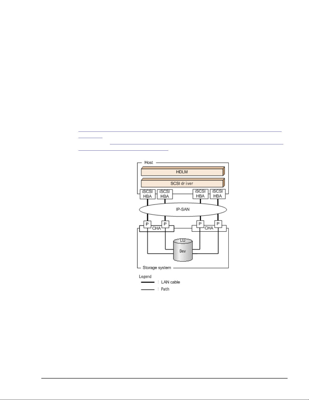
Figure 2-2 Configuration of an IP-SAN System When Using an iSCSI HBA on
page 2-5 shows the configuration of an IP-SAN system when using an
iSCSI HBA.
Software and an NIC on page 2-6 shows the configuration of an IP-SAN
system when using the iSCSI software and an NIC.
Figure 2-3 Configuration of an IP-SAN System When Using iSCSI
Figure 2-2 Configuration of an IP-SAN System When Using an iSCSI HBA
HDLM Functions
Hitachi Dynamic Link Manager (for Windows®) User Guide
2-5
Page 26
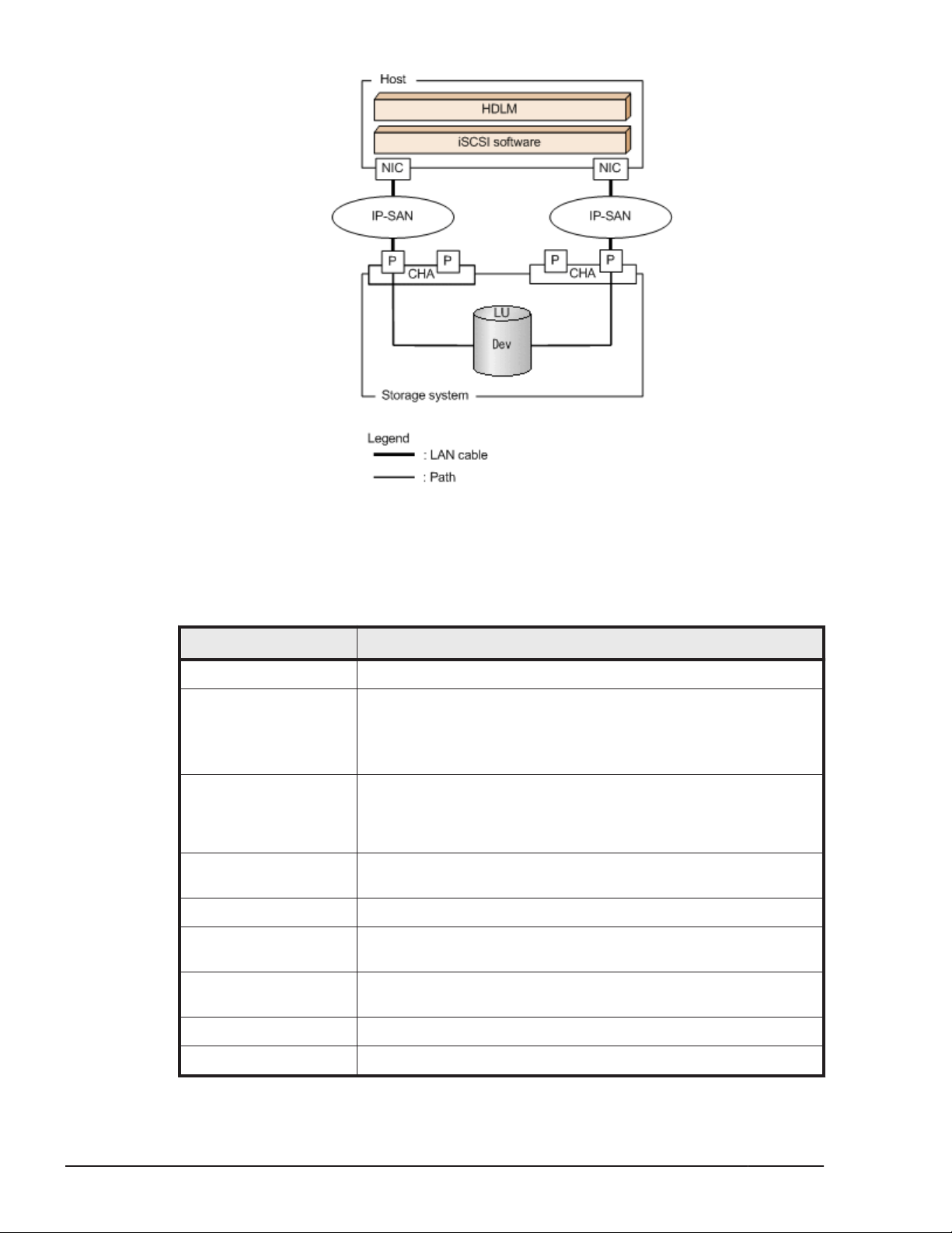
Figure 2-3 Configuration of an IP-SAN System When Using iSCSI Software
and an NIC
The following table lists the HDLM system components when using an IP-SAN.
Table 2-2 HDLM System Components When Using an IP-SAN
Components Description
iSCSI software The driver software that contains the iSCSI initiator function
iSCSI HBA A host bus adapter that contains the iSCSI initiator function.
This serves as a cable port on a host. The iSCSI HBA is referred
to as the HBA in HDLM commands and the HDLM GUI.
Sometimes, it is also just simply called an HBA in this manual.
NIC A network interface card that serves as a cable port on a host.
The NIC is referred to as the HBA in HDLM commands and the
HDLM GUI. Sometimes, it is also just simply called an HBA in
this manual.
IP-SAN A data transfer network that connects hosts and storage
systems by using the iSCSI standard.
CHA A channel adapter used for iSCSI connections
P A port on a CHA. This serves as a cable port on a storage
system.
2-6
LU A logical unit with which the host can perform I/O operations.
This unit can be accessed from the network.
Dev A logical area (a partition) in an LU
Path A route that connects a host to a Dev in an LU
HDLM Functions
Hitachi Dynamic Link Manager (for Windows®) User Guide
Page 27

Setting Range of the iSCSI Software and iSCSI HBA
The following describes the ranges that can be used for the iSCSI software
and iSCSI HBA settings. For notes on how to set these values, see the
corresponding documentation for your particular iSCSI software and iSCSI
HBA.
• IP addresses
Use the same network address for both an HBA and a CHA port connected
via a common path.
• Other settings
¢
An IP-SAN can be used for multiple hosts.
¢
A single HBA can connect to multiple CHA ports.
When using the iSCSI software together with multiple NICs, be sure to
connect each NIC to a different IP network. Also, be sure to connect to the
storage system by using a different CHA port for each IP network. To view an
example of the configuration described above, see
an IP-SAN System When Using iSCSI Software and an NIC on page 2-6.
Storage systems Supported by HDLM
The following storage systems can be used with an IP-SAN: the Lightning
9900V series, Hitachi AMS/WMS series, Hitachi Universal Storage Platform
100, Hitachi Universal Storage Platform 600, Hitachi Universal Storage
Platform 1100, Hitachi NSC 55, and Hitachi SMS series.
Figure 2-3 Configuration of
LU Configuration
After you have properly installed HDLM, the LU configuration will change as
follows:
Before the installation of HDLM:
In the Windows' Disk Management window of a host, one SCSI device is
displayed as multiple LUs, each of which corresponds to one path.
In other words, the number of LUs in a storage system appeared to be
the same as the number of paths connected to the various SCSI devices.
After the installation of HDLM:
The MPIO driver combines what was once viewed as multiple LUs (each
with one path) into one LU containing multiple paths. In the Windows'
Disk Management window of a host, only the disks that have a one-toone correspondence with an LU in the storage system are displayed.
This means that each LU in the storage system is always recognized as
only one LU, regardless of the number of paths that are connected to
SCSI devices.
You can display all the various SCSI devices from the Windows' Device
Manager window.
HDLM Functions
Hitachi Dynamic Link Manager (for Windows®) User Guide
2-7
Page 28
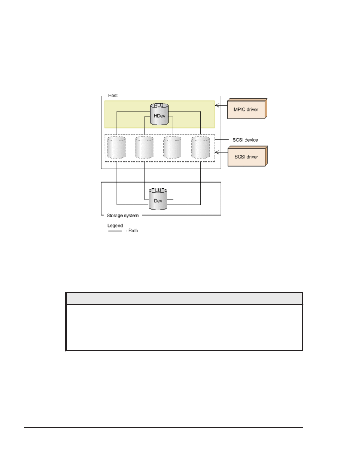
After the installation of HDLM, an LU recognized by a host is called a host LU
(HLU). The areas in a host LU that correspond to the Devs in a storage
system LU are called host devices (HDev).
On a system using HDLM, in order to access a target LU, a drive letter is first
assigned to the disk that has been integrated by the MPIO driver. Such disks
are displayed in the Windows' Disk Management window.
The following figure shows the LU configuration recognized by the host, after
the installation of HDLM.
Figure 2-4 LU Configuration Recognized by the Host After the Installation
of HDLM
The following table lists and describes the components recognized by the
host.
Table 2-3 Components Recognized by the Host
Components Description
HLU An LU that the host recognizes via the HDLM driver. This
type of LU is called a host LU. Regardless of how many
paths are connected to it, only one host LU is recognized
for each LU in the storage system.
HDev A Dev in an LU that the host recognizes via the HDLM
driver. This type of Dev is called a host device.
2-8
HDLM Functions
Hitachi Dynamic Link Manager (for Windows®) User Guide
Page 29
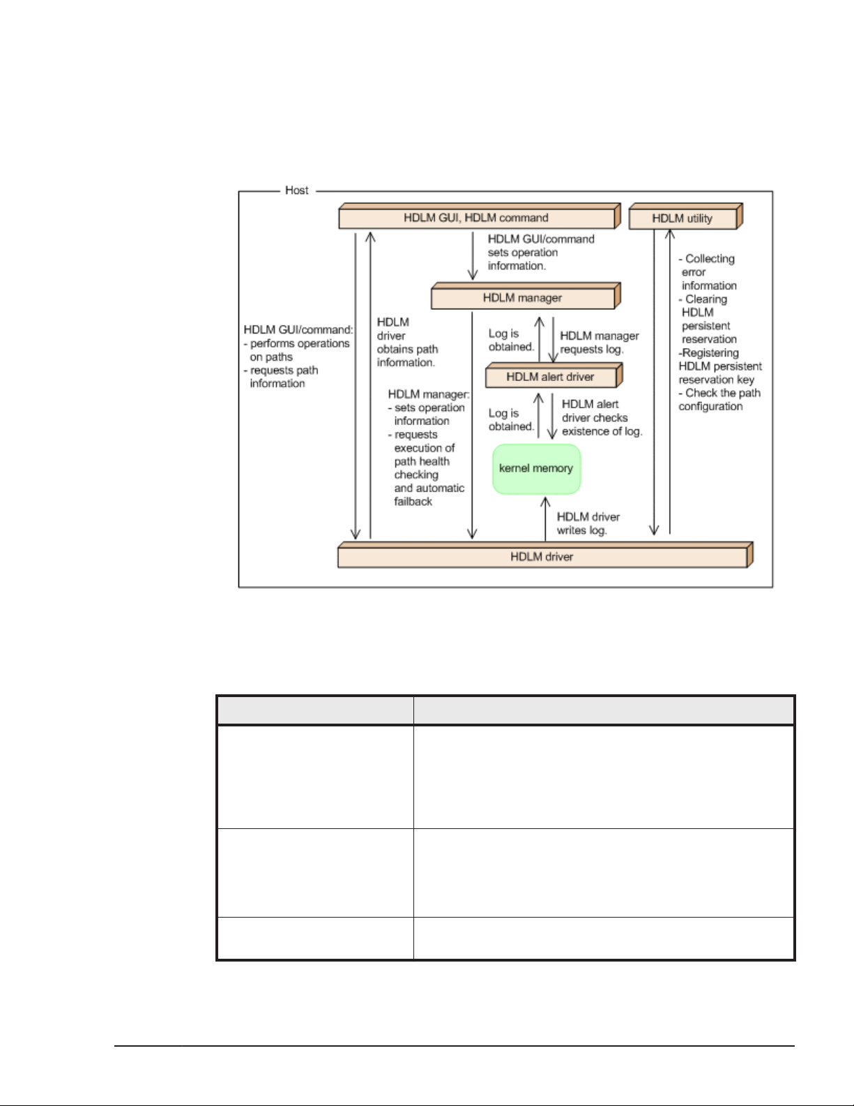
Program Configuration
HDLM is actually a combination of several programs. Because each program
corresponds to a specific HDLM operation, it is important to understand the
name and purpose of each program, along with how they are all interrelated.
The following figure shows the configuration of the HDLM programs.
Figure 2-5 Configuration of the HDLM Programs
The following table lists and describes the functions of these programs.
Table 2-4 Functions of HDLM Programs
Program name Functions
HDLM GUI Provides a graphical user interface (GUI), which enables
you to:
• Manage paths
• Display error information
• Set up the HDLM operating environment
HDLM command Provides the dlnkmgr command, which enables you to:
• Manage paths
• Display error information
• Set up the HDLM operating environment
HDLM utility Provides the HDLM utility, which enables you to:
• Collect error information
HDLM Functions
Hitachi Dynamic Link Manager (for Windows®) User Guide
2-9
Page 30

Program name Functions
• Clear persistent reservations
• Register persistent reservation keys
• Check the configuration of the paths
• Check the installation information
• Perform unattended installations of HDLM
• Perform unattended removals of HDLM
HDLM manager Provides the HDLM manager, which enables you to:
• Configure the operating environment
• Request path health checks and automatic failbacks
to be performed
• Collect error log data
HDLM alert driver Reports the log information collected by the HDLM driver
to the HDLM manager.
HDLM driver Controls all the HDLM functions, manages paths, and
detects errors. The HDLM driver consists of the following:
• Core logic component
Controls the basic functionality of HDLM.
• Filter component
Sends and receives I/O data. The driver name is
hdlmdsm.sys.
Note:
HDLM programs other than the HDLM GUI are referred to as the HDLM
Core components.
Driver Levels of the HDLM and MPIO Drivers
The HDLM and MPIO drivers are positioned at a higher driver level than the
SCSI drivers. In other words, applications that are accessing LUs in storage
systems will first use the HDLM and MPIO drivers, and then use the SCSI
drivers, in order to access the LUs.
The following figure shows the driver levels of the HDLM and MPIO drivers.
2-10
HDLM Functions
Hitachi Dynamic Link Manager (for Windows®) User Guide
Page 31
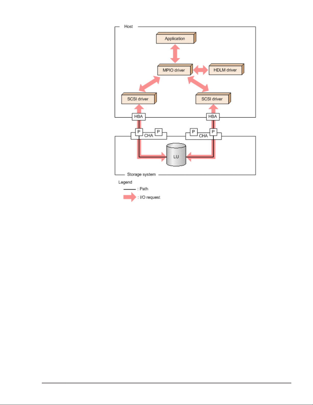
Figure 2-6 Driver Levels of the HDLM and MPIO Drivers
Distributing a Load Using Load Balancing
When the system contains multiple paths to a single LU, HDLM can distribute
the load across the paths by using multiple paths to transfer the I/O data.
This function is called load balancing, and it prevents a single, heavily loaded
path from affecting the performance of the entire system.
Note that some I/O operations managed by HDLM can be distributed across
all, available paths, and some cannot. Therefore, even when the load
balancing function is used, a particular I/O operation might not necessarily
allocate data to every available path. RAID Manager issuing IOCTL to a
command device is an example of an I/O operation that cannot allocate data
to every path.
Note:
Do not use the load balancing function that is accessible from the
Microsoft iSCSI Software Initiator user interface.
In a cluster environment, the load balancing function is available for the
Thunder 9500V series, Lightning 9900V series, Hitachi
AMS2000/AMS/WMS/SMS series, Hitachi USP series, Universal Storage
HDLM Functions
Hitachi Dynamic Link Manager (for Windows®) User Guide
2-11
Page 32

Platform V/VM series, and Virtual Storage Platform series. In a non-cluster
environment, the load balancing function is available for the Thunder 9500V
series, Lightning 9900V series, Hitachi AMS2000/AMS/WMS/SMS series,
Hitachi USP series, Universal Storage Platform V/VM series, Virtual Storage
Platform series, and EMC DMX series. For details on the various cluster
software that HDLM supports, see Cluster Support on page 2-46.
Figure 2-7 Flow of I/O Data When the Load Balancing Function Is Not Used on
page 2-12 shows the flow of I/O data when the load balancing function is
not used.
Used on page 2-13 shows the flow of I/O data when the load balancing
function is used. Both figures show examples of I/O operations being issued
for the same LU by multiple applications.
Figure 2-8 Flow of I/O Data When the Load Balancing Function Is
2-12
Figure 2-7 Flow of I/O Data When the Load Balancing Function Is Not
Used
When the load balancing function is not used, I/O operations converge onto a
single path (A). The load on that one path (A) will cause a bottleneck, which
might cause problems with system performance.
HDLM Functions
Hitachi Dynamic Link Manager (for Windows®) User Guide
Page 33

Figure 2-8 Flow of I/O Data When the Load Balancing Function Is Used
When the load balancing function is used, I/O operations are distributed via
multiple paths (A, B, C, and D). This helps to prevent problems with system
performance and helps prevent bottlenecks from occurring.
Paths to Which Load Balancing Is Applied
This subsection describes, for each type of storage system, the paths to
which the load balancing function is applied.
When Using the Thunder 9500V Series, or Hitachi AMS/WMS Series
When HDLM performs load balancing, it differentiates between load balancing
among owner paths and among non-owner paths. An owner path is a path
that passes through the owner controller for a target LU. When you set up an
LU, you have to specify which CHA to be used as the owner controller for the
LU. Because different LUs might have different owner controllers, different
LUs might also have different owner paths. A non-owner path is a path that
passes through a CHA other than the owner controller. This type of CHA is
also known as a non-owner controller. An owner path is usually used in
preference to a non-owner path. In order to prevent system performance
from slowing down, HDLM does not perform load balancing between owner
paths and non-owner paths. If failures occur across some of the owner paths,
HDLM Functions
Hitachi Dynamic Link Manager (for Windows®) User Guide
2-13
Page 34

load balancing will be performed among the remaining, usable owner paths.
It is only when absolutely no owner paths are available, that load balancing is
then performed among the non-owner paths.
For the example in Figure 2-9 Overview of Load Balancing on page 2-14,
suppose that in the owner controller of LU0 is CHA0. When the LU is
accessed, the load is balanced between the two paths A and B, which are
both owner paths. When one of the paths (A) cannot be used, then the LU is
accessed from the only other owner path (B). When both of the owner paths
(A and B) cannot be used, the load is then balanced between two other, nonowner paths (C and D).
Figure 2-9 Overview of Load Balancing
When Using Other Than the Thunder 9500V Series and Hitachi AMS/WMS Series
All online paths are owner paths. Therefore, for the example in Figure 2-8
Flow of I/O Data When the Load Balancing Function Is Used on page 2-13,
the load is balanced among the four paths A, B, C, and D. If one of the paths
were to become unusable, the load would be balanced among the three,
remaining paths.
Notes:
Load balancing is performed for the following storage systems:
¢
Lightning 9900V series
¢
Hitachi USP series
¢
Universal Storage Platform V/VM series
¢
Virtual Storage Platform series
2-14
Hitachi Dynamic Link Manager (for Windows®) User Guide
HDLM Functions
Page 35

¢
VSP G1000 series
¢
Hitachi AMS2000 series
¢
Hitachi SMS series
¢
HUS100 series
¢
HUS VM
#: This storage system applies when the dynamic I/O path control
function is disabled.
Load Balancing Algorithms
HDLM has the following six load balancing algorithms:
• The Round Robin algorithm
• The Extended Round Robin algorithm
• The Least I/Os algorithm
• The Extended Least I/Os algorithm
• The Least Blocks algorithm
• The Extended Least Blocks algorithm
The above algorithms are divided into two categories, which differ in their
processing method. The following describes both of these processing
methods:
#
#
#
The Round Robin, Least I/Os, and Least Blocks algorithms
These algorithms select which path to use every time an I/O is issued.
The path that is used is determined by the following:
¢
Round Robin
The paths are simply selected in order from among all the connected
paths.
¢
Least I/Os
The path that has the least number of I/Os being processed is
selected from among all the connected paths.
¢
Least Blocks
The path that has the least number of I/O blocks being processed is
selected from among all the connected paths.
The Extended Round Robin, Extended Least I/Os, and Extended Least Blocks
algorithms
These algorithms determine which path to allocate based on whether the
data of the I/O to be issued is sequential with the data of the I/O that
was issued immediately beforehand.
If the data is sequential, the path used will be the one to which the data
of the I/O that was issued immediately beforehand was distributed.
However, if a specified number of I/Os has been issued to a path,
processing switches to the next path.
HDLM Functions
Hitachi Dynamic Link Manager (for Windows®) User Guide
2-15
Page 36

If the data is not sequential, these algorithms select the path to be used
each time an I/O request is issued.
¢
Extended Round Robin
The paths are simply selected in order from among all the connected
paths.
¢
Extended Least I/Os
The path that has the least number of I/Os being processed is
selected from among all the connected paths.
¢
Extended Least Blocks
The path that has the least number of I/O blocks being processed is
selected from among all the connected paths.
The following table lists and describes the features of the load balancing
algorithms.
Table 2-5 Features of the Load Balancing Algorithms
Algorithm type Algorithm features
•
Round Robin
• Least I/Os
• Least Blocks
• Extended Round
Robin
• Extended Least I/Os
• Extended Least
Blocks
#
These types of algorithms are most effective when a lot of
discontinuous, non-sequential I/Os are issued.
If the I/O data is from something like a read request and is
generally sequential with the previous I/Os, an improvement
in reading speed can be expected due to the storage system
cache functionality. These types of algorithms are most
effective when a lot of continuous, sequential I/Os are issued.
#
Some I/O operations managed by HDLM can be distributed across all,
available paths, and some cannot. Thus, you should be aware that even if
you specify the Round Robin algorithm, some of the I/O operations will
never be issued uniformly across all the given paths.
The default algorithm is the Extended Least I/Os algorithm, which is set when
HDLM is first installed. When an upgrade installation of HDLM is performed,
the algorithm that is currently being used is inherited.
Select the load balancing algorithm most suitable for the data access patterns
of your system environment. However, if there are no recognizable data
access patterns, we recommend using the default algorithm, the Extended
Least I/Os algorithm.
2-16
You can specify the load balancing function from the Options window of the
HDLM GUI or by using the dlnkmgr command's set operation. For details on
how to use the window components, see the HDLM GUI Help. For details on
the set operation, see
set (Sets Up the Operating Environment) on page
6-16.
HDLM Functions
Hitachi Dynamic Link Manager (for Windows®) User Guide
Page 37

Performing Failovers and Failbacks Using Path Switching
When the system contains multiple paths to an LU and an error occurs on the
path that is currently being used, HDLM can switch to another functional
path, so that the system can continue operating. This is called a failover.
If a path in which an error has occurred recovers from the error, HDLM can
then switch back to that path. This is called a failback.
Two types of failovers and failbacks are available:
• Automatic failovers and failbacks
• Manual failovers and failbacks
Failovers and failbacks switch which path is being used and also change the
statuses of the paths. A path status is either online or offline. An online status
means that the path can receive I/Os. On the other hand, an offline status
means that the path cannot receive I/Os. A path will go into the offline status
for the following reasons:
• An error occurred on the path.
• A user intentionally placed the path offline by using the Path Management
window in the HDLM GUI.
• A user executed the HDLM command's offline operation.
For details on the offline operation, see
page 6-6.
• Hardware, such as cables or HBAs, has been removed.
offline (Places Paths Offline) on
For details on path statuses and the transitions of those statuses, see
Status Transition on page 2-20.
Automatic Path Switching
The following describes the automatic failover and failback functions, which
automatically switch a path.
Automatic Failovers
If you detect an error on the path that is currently being used, you can
continue to use the system by having the status of that path automatically
changed to offline, and then automatically have the system switch over to
another online path. This functionality is called automatic failover. Automatic
failovers can be used for the following levels of errors:
Critical
A fatal error that might stop the system.
Error
A high-risk error, which can be avoided by performing a failover or some
other countermeasure.
For details on error levels, see Filtering of Error Information on page 2-36.
Path
HDLM Functions
Hitachi Dynamic Link Manager (for Windows®) User Guide
2-17
Page 38

If the Thunder 9500V series, or Hitachi AMS/WMS series is being used, HDLM
will select the path to be used next from among the various paths that access
the same LU, starting with owner paths, and then non-owner paths.
For example, in Figure 2-10 Path Switching on page 2-18, the owner
controller of an LU is CHA0, and access to the LU is made via only one path
(A). After that access path (A) is placed offline, the first choice for the
switching destination is the other path connected to CHA0 (B). If an error
also occurs on that path (B), then the next possibility for a path comes from
one of the two paths (C or D) connected to CHA1.
When the Lightning 9900V series, Hitachi USP series, Universal Storage
Platform V/VM series, Virtual Storage Platform series, VSP G1000 series,
Hitachi AMS2000 series#, Hitachi SMS series#, HUS100 series#, or HUS VM is
being used, all the paths are owner paths. This means that all the paths that
are accessing the same LU are possible switching destinations. For example,
Figure 2-10 Path Switching on page 2-18, the LU is accessed using only
in
the one path (A). However, after that path is placed offline, the switching
destination can come from any of the other three paths (B, C, or D).
#
This storage system applies when the dynamic I/O path control function is
disabled.
2-18
Figure 2-10 Path Switching
HDLM Functions
Hitachi Dynamic Link Manager (for Windows®) User Guide
Page 39

Automatic Failbacks
When a path recovers from an error, HDLM can automatically place the
recovered path back online. This function is called the automatic failback
function.
In order to use the automatic failback function, HDLM must already be
monitoring error recovery on a regular basis.
When using the Thunder 9500V series, or Hitachi AMS/WMS series, HDLM will
select the next path to be used first from among the online owner paths, and
then from the online non-owner paths. As a result, if an owner path recovers
from an error, and then HDLM automatically places the recovered path online
while a non-owner path is in use, the path will be automatically switched over
from the non-owner path to the owner path that just recovered from the
error.
When the Lightning 9900V series, Hitachi USP series, Universal Storage
Platform V/VM series, Virtual Storage Platform series, VSP G1000 series,
Hitachi AMS2000 series#1, Hitachi SMS series #1, HUS100 series#1 or HUS
VM is being used, all the paths are owner paths. As a result, if the path that
was previously used recovers from an error, and then HDLM automatically
places the recovered path online, the path that is currently being used will
continue to be used (as opposed to switching over to the path that was just
recovered).
When intermittent errors#2 occur on paths and you are using the automatic
failback function, the path status might frequently alternate between the
online and offline statuses. In such a case, because the performance of I/Os
will most likely decrease, if there are particular paths in which intermittent
errors might be occurring, we recommend that you set up intermittent error
monitoring so you can detect these paths, and then remove them from those
subject to automatic failbacks.
You can specify the automatic failback or intermittent error monitoring
function from the Options window of the HDLM GUI or by using the dlnkmgr
command's set operation. For details on operations from the Options
window, see the HDLM GUI Help. For details on the set operation, see
(Sets Up the Operating Environment) on page 6-16.
#1
This storage system applies when the dynamic I/O path control function is
disabled.
#2
An intermittent error means an error that occurs irregularly because of
some reason such as a loose cable connection.
Manual Path Switching
set
You can switch the status of a path by manually placing the path online or
offline. Manually switching a path is useful, for example, when system
maintenance needs to be done.
HDLM Functions
Hitachi Dynamic Link Manager (for Windows®) User Guide
2-19
Page 40

You can manually place a path online or offline by doing the following:
• Use the HDLM GUI Path Management window.
• Execute the dlnkmgr command's online or offline operation.
For details on the online operation, see online (Places Paths Online) on
page 6-11. For details on the offline operation, see offline (Places
Paths Offline) on page 6-6.
However, if there is only one online path for a particular LU, that path cannot
be manually switched offline. Also, a path with an error that has not been
recovered from yet cannot be switched online.
HDLM uses the same algorithms to select the path that will be used next,
regardless of whether automatic or manual path switching is used.
When using the Thunder 9500V series, or Hitachi AMS/WMS series, HDLM will
select the next path to be used first from among the online owner paths, and
then from the online non-owner paths. When the Lightning 9900V series,
Hitachi USP series, Universal Storage Platform V/VM series, Virtual Storage
Platform series, VSP G1000 series, Hitachi AMS2000 series#, Hitachi SMS
series#, HUS100 series#, or HUS VM is being used, all the paths that access
the same LU as the path that is currently being used are candidates for the
switching destination path.
By changing the path status to online in the Path Management window, or by
executing the online operation, an offline path can be placed online. For
details on the online operation, see
6-11. After a path status is changed to online, the path can be selected as a
useable path by HDLM in the same manner as automatic path switching.
When using the Thunder 9500V series, or Hitachi AMS/WMS series, HDLM
selects the path to use from online owner paths, and then from online nonowner paths. When the Lightning 9900V series, Hitachi USP series, Universal
Storage Platform V/VM series, Virtual Storage Platform series, VSP G1000
series, Hitachi AMS2000 series#, Hitachi SMS series#, HUS100 series#, or
HUS VM is being used, since all the paths are owner paths, the path to use is
not switched even if you change the path status to online by using the Path
Management window or the online operation.
For details on how to change the path status in the Path Management
window, see the HDLM GUI Help.
#
This storage system applies when the dynamic I/O path control function is
disabled.
Path Status Transition
online (Places Paths Online) on page
2-20
Each of the online and offline statuses described in
Failbacks Using Path Switching on page 2-17 is further subdivided into
several statuses. The path statuses (the online path statuses and offline path
statuses) are explained below.
HDLM Functions
Hitachi Dynamic Link Manager (for Windows®) User Guide
Performing Failovers and
Page 41

The Online Path Statuses
The online path statuses are as follows:
• Online
I/Os can be issued normally.
• Online(P)
A state in which a path in the Online status is in the waiting-to-execute
status to be taken offline.
This status occurs in a cluster configuration only.
The Online(P) status indicates that the user has requested an Online
path to be taken offline, for a path that is connected to an LU that is
currently performing reserve processing. I/O operations can still be issued
normally until the reserve processing on the LU finishes. After the reserve
processing finishes, the offline operation request will be performed and
the path status will become Offline(C).
The (P) means pending, which indicates that the operation to take the
path offline is in the waiting-to-execute status (i.e. a request has been
made).
• Online(E)
An error has occurred on the path, but none of the other paths that
access the same LU are in the Online status.
If none of the paths accessing a particular LU are in the Online status,
one of the paths is changed to the Online(E) status. This ensures that
the LU can be accessed through at least one path.
The (E) means error, which indicates that an error has occurred on the
path from some previous operation.
• Online(EP)
The status of an Offline(P) path changes to Online(EP) when the path
goes through the following process during reserve processing in a cluster
configuration:
a. When exactly two paths are connected to an LU and the user performs
an offline operation on the Offline(E) path to change it to
Offline(P) and the other path is Online(E).
b. When one path is Offline(P), the other path must be Online(E). If
HDLM detects an error in the Online(E) path, then the path statuses
will change as follows:
The Online(E) path changes to Offline(E).
The Offline(P) path changes to Online(EP).
If the reserve processing finishes after the path has changed from
Online(EP) to Offline(P), the offline operation will end successfully and
the path will change to Offline(C).
If the reserve processing finishes while the path is Online(EP), the offline
operation will fail and the path will change to Online(E).
•
Online(S)
Hitachi Dynamic Link Manager (for Windows®) User Guide
#
HDLM Functions
2-21
Page 42

The paths to the primary volume (P-VOL) in the HAM environment have
recovered from an error, but I/O to the P-VOL is suppressed.
•
Online(D)
The paths to the primary volume (P-VOL) in an HAM environment have
recovered from an error, but I/O to the P-VOL is suppressed. If an error
occurs in all the paths to a secondary volume (S-VOL), the status of the
P-VOL paths will be automatically changed to the Online status. To
change the status to the Online(D) status, specify the -dfha parameter
for the HDLM command's online operation.
#
The status changes to this status when using HAM (High Availability
Manager).
The Offline Path Statuses
The offline path statuses are as follows:
• Offline(C)
The path is offline because an offline operation was performed.
The (C) indicates the command attribute, which indicates that the path
was placed offline by using the GUI or a command.
• Offline(E)
The status indicating that an I/O could not be issued on a given path,
because an error occurred on the path.
The (E) means error.
• Offline(P)
This status occurs in a cluster configuration only.
The Offline(P) status indicates that the user has requested an offline
operation on an Offline(E) path that is connected to an LU that is
currently performing reserve processing. After the reserve processing
finishes, the offline operation request will be performed and the path
status will become Offline(C).
The (P) means pending, which indicates that the operation to take the
path offline is in the waiting-to-execute status (i.e. a request has been
made).
#
Status Transitions of a Path
The following figure shows the status transitions of a path.
2-22
Hitachi Dynamic Link Manager (for Windows®) User Guide
HDLM Functions
Page 43

Figure 2-11 Path Status Transitions
Legend:
Online operation: Online operation performed in the Path Management
window or by executing the dlnkmgr command's online operation.
Offline operation: Offline operation performed in the Path Management
window or by executing the dlnkmgr command's offline operation.
#1
During reserve processing for an LU, the Online status is temporarily
changed to Online(P). When the reservation processing finishes, the
Online(P) status is changed to Offline(C).
#2
When the following conditions are satisfied, the connected Offline(C)
paths are automatically placed online:
¢
All the online paths are Online(E) and all the SCSI devices connected
to the Online(E) paths have been deleted.
¢
SCSI devices are connected and all the Offline(E) paths are subject
to automatic failback.
¢
SCSI devices are connected to the Offline(C) paths.
#3
When a path is added dynamically, initially the path status is Offline(C).
The path status will then automatically change to Online. For details on
dynamically adding a path, see Setting Up an Added LU and Path as an
HDLM Management-target on page 4-16.
#4
HDLM Functions
Hitachi Dynamic Link Manager (for Windows®) User Guide
2-23
Page 44
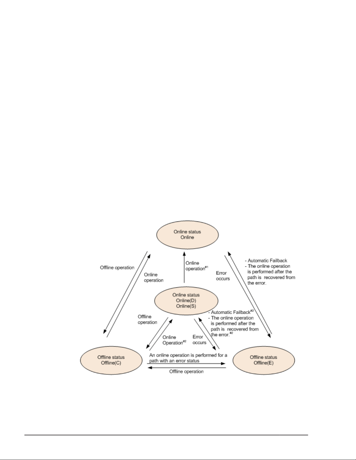
When the following conditions are all satisfied, a path that has been
determined to have an intermittent error also becomes subject to
automatic failback:
¢
All the paths connected to an LU are Online(E), Offline(E), or
Offline(C).
¢
All the paths connected to an LU have been determined to have an
intermittent error.
¢
The processing of continuous I/O operations issued to an LU is
successful.
#5
During reserve processing for an LU, the Offline(E) status is temporarily
changed to Offline(P). After the reserve processing finishes, the
Offline(P) status is changed to Offline(C).
#6
When the following conditions are satisfied, the connected Offline(E)
paths are automatically placed online:
¢
All the online paths are Online(E) and all the SCSI devices connected
to the Online(E) paths have been deleted.
¢
The Offline(E) paths are assumed to have had an intermittent error,
and are thus excluded from automatic failbacks.
¢
The SCSI devices are connected to the Offline(E) paths.
2-24
Figure 2-12 Path Status Transitions (P-VOL in HAM environment)
Legend:
HDLM Functions
Hitachi Dynamic Link Manager (for Windows®) User Guide
Page 45

Online operation: Online operation performed by executing the dlnkmgr
command's online operation.
Offline operation: Offline operation performed by executing the dlnkmgr
command's offline operation.
#1
Also when an error occurs in all the paths to an S-VOL in the Online(D)
status.
#2
When I/O operations are processed on an S-VOL.
If there is only one available online path for an LU, it cannot be placed offline
by using the Path Management window or by executing the offline
operation. This ensures that the LU can always be accessed by at least one
path. For details on the offline operation, see
on page 6-6.
If an error occurs in the only available online path for an LU, the status of the
path will change to Online(E).
If you are using the automatic failback function, after the path has recovered
from the error, HDLM will automatically place the path online. There are,
however, the following exceptions:
offline (Places Paths Offline)
• When you are using intermittent error monitoring, sometimes, the path in
which the intermittent error occurred is not automatically placed online
after the path has been recovered from the error. If this happens,
manually place the path online. If the only other online path is in the
Online(E) status when the path is recovered from the error, the path
recovered from the error might be placed online automatically. For
details, see
Does Not Occur on a Path on page 2-28.
• There are cases in which the path is automatically placed online even if
you are not using the automatic failback function. If a piece of hardware
that supports the Windows plug-and-play function is removed, HDLM will
place the path associated with that hardware offline, as well. If the
hardware is then re-installed, HDLM will automatically place the path back
online. However, this is the case only when there is no other cause or
reason for the path being placed offline. In this case, because HDLM will
automatically place the path back online without using the automatic
failback function, you do not need to manually place the path online.
When you use the LU dynamic deletion function, the Online(E) path will be
deleted. Therefore, that path is not displayed in the Path Management
window. Also, the view operation does not display the Online(E) path.
Note:
If there is a path failure immediately after a path is taken offline by using
either the an HDLM command or the HDLM GUI, the status might change
from Offline(C) to Offline(E). If an offline operation was just
performed, wait about 2 minutes, check the path status by using an
Figure 2-14 What Will Happen When an Intermittent Error
HDLM Functions
Hitachi Dynamic Link Manager (for Windows®) User Guide
2-25
Page 46

HDLM command or the HDLM GUI, and then make sure that the status
has changed to Offline(C). If it is still Offline(E), retry the offline
operation.
Monitoring Intermittent Errors (Functionality When Automatic Failback Is Used)
An intermittent error refers to an error that occurs irregularly because of
something like a loose cable. In such a case, I/O performance might decrease
while an automatic failback is being performed to repair an intermittent error.
This is because the automatic failback operation is being performed
repeatedly (because the intermittent error keeps occurring). To prevent this
from happening, HDLM can automatically remove the path where an
intermittent error is occurring from the paths that are subject to automatic
failbacks. This process is called intermittent error monitoring.
We recommend that you use intermittent error monitoring along with the
automatic failback function.
A path in which an error occurs a specified number of times within a specified
interval is determined to have an intermittent error. The path where an
intermittent error occurs has an error status until the user chooses to place
the path back online. Failbacks are not performed for such paths. This status
is referred to as the not subject to auto failback status.
Checking Intermittent Errors
You can check the paths in which intermittent errors have occurred by
viewing the execution results of the HDLM command's view operation or the
HDLM GUI Path List view.
For details on the view operation, see
6-33. For details on how to use the Path List view of the HDLM GUI and
window components, see the HDLM GUI Help.
view (Displays Information) on page
Setting Up Intermittent Error Monitoring
When you enable the intermittent error monitoring function, specify the
following monitoring conditions: the error monitoring interval, and the
number of times that the error needs to occur. If an error occurs on a
particular path the specified number of times within the specified errormonitoring interval, then an intermittent error will occur on the path. For
example, if you specify 30 for the error monitoring interval and 3 for the
number of times that the error needs to occur, the path is determined to
have an intermittent error if an error occurs 3 or more times in 30 minutes.
You can set up intermittent error monitoring by executing the dlnkmgr
command's set operation or using the HDLM GUI Options window.
2-26
Intermittent error monitoring can be used only when automatic failback has
already been enabled. The values that can be specified for intermittent error
HDLM Functions
Hitachi Dynamic Link Manager (for Windows®) User Guide
Page 47

monitoring depend on the values specified for automatic failbacks. For details
on how to specify the settings, see set (Sets Up the Operating Environment)
on page 6-16 or the HDLM GUI Help.
Intermittent Error Monitoring Actions
Intermittent error monitoring is performed on each path, and it automatically
starts as soon as a path is recovered from an error by using the automatic
failback function.
This subsection describes the following intermittent error monitoring actions:
• When an intermittent error occurs
• When an intermittent error does not occur
• When the conditions for an intermittent error to occur are changed during
error monitoring
When an Intermittent Error Occurs
When an error occurs on a path a specified number of times within a specified
interval, the error monitoring will finish and the path is determined to have
an intermittent error, upon which the path is removed from those subject to
automatic failbacks. The path that is removed will remain in the error status
until the online operation is performed. However, if the path satisfies certain
conditions (see
subject to automatic failbacks and change to the Online status.
Figure 2-11 Path Status Transitions on page 2-23), it will be
The figure below shows the action taken when an intermittent error is
assumed to have occurred on the path. For this example, the path is
determined to have an intermittent error when the error occurs 3 or more
times within 30 minutes. The events that occur are described by using the
time arrows.
Figure 2-13 Action What Will Happen When an Intermittent Error Occurs
on a Path
HDLM Functions
Hitachi Dynamic Link Manager (for Windows®) User Guide
2-27
Page 48

When an Intermittent Error Does Not Occur
If an error does not occur on a path a specified number of times within a
specified interval, an intermittent error will not occur. In such a case, the
error monitoring will finish when the specified error-monitoring interval
finishes, upon which the number of errors is reset to 0. If an error occurs on
the path again at a later time, error monitoring will resume when the path is
recovered from the error via an automatic failback.
If it takes a long time for an error to occur, an intermittent error can be more
easily detected by increasing the error-monitoring interval or by decreasing
the number of times that the error needs to occur.
The figure below shows the action taken when an intermittent error is
assumed not to have occurred on the path. For this example, the path is
determined to have an intermittent error if the error occurs three or more
times in 30 minutes. The events that occur are described by using the time
arrows.
Figure 2-14 What Will Happen When an Intermittent Error Does Not Occur
on a Path
As shown in Figure 2-14 What Will Happen When an Intermittent Error Does
Not Occur on a Path on page 2-28, normally, the count for the number of
times that an error occurs is started after the path is first recovered from an
error by using the automatic failback function. However, if all the paths
connected to the LU are in the Offline(E), Online(E), or Offline(C) status
(which is due to the disconnection of the paths or some other reason), the
paths will not be recovered and put back online by using the automatic
failback function. If I/O operations are continuously being issued to such an
LU, the count for the number of times that the error occurs might be started
even though the path will not be placed online. If the number of times that
the error occurs reaches the specified value, the path is determined to have
an intermittent error. In such a case, remove the cause of the error, and then
manually place the path online.
When the Conditions for an Intermittent Error Are Changed During Error
Monitoring
When the conditions for an intermittent error are changed during error
monitoring, the number of errors and the amount of time that has passed
2-28
HDLM Functions
Hitachi Dynamic Link Manager (for Windows®) User Guide
Page 49

since the error monitoring started are both reset to 0. As such, the error
monitoring will not finish, and it will start over by using the new conditions.
If the conditions are changed while error monitoring is not being performed,
error monitoring will start up again and use the updated conditions after any
given path is recovered from an error by performing an automatic failback.
The figure below shows the action taken when the conditions for an
intermittent error are changed during intermittent error monitoring. For this
example, the conditions have been changed from 3 or more errors in 30
minutes, to 3 or more errors in 40 minutes. The events that occur are
described by using the time arrows.
Figure 2-15 What Will Happen When Conditions Are Changed During Error
Monitoring
When a User Changes the Intermittent Error Information
The following might be reset when a user changes any of the values set for
the intermittent error or the path status: the number of errors that have
already been counted during error monitoring, the amount of time that has
passed since error monitoring has started, and the information about whether
an intermittent error has occurred.
Changing the Intermittent Error Information on page 2-30 lists whether the
above items are reset.
If you want to check whether intermittent error monitoring is being used for a
path, check the IEP item displayed when the dlnkmgr command's view -path
operation is executed with the -iem parameter specified, or the Intermittent
Error Path item specified in the Path List view of the HDLM GUI. If 0 or
greater is displayed in the Intermittent Error Path item, then intermittent
error monitoring is being performed.
Table 2-6 When Effects of a User
HDLM Functions
Hitachi Dynamic Link Manager (for Windows®) User Guide
2-29
Page 50

Table 2-6 When Effects of a User Changing the Intermittent Error
Information
Changing the
intermittent error
monitoring settings
User operation
Turning off Reset
Changing the conditions for
an intermittent error while
intermittent error monitoring
is being performed
Turning intermittent error
monitoring on by executing
the set operation, (but not
changing the conditions)
while intermittent error
monitoring is being
performed
Clicking the Apply or OK
button in the HDLM GUI
Options window#3 while
intermittent error monitoring
is being performed
Number of
errors and time
passed since
error
monitoring
started
#2
Reset
Information
about paths
not subject to
automatic
failback
#1
Reset
Inherited
Changing the intermittent
error monitoring conditions
while intermittent error
monitoring is not being
performed
Changing the
automatic failback
settings
Changing the path
status
Restarting the HDLM manager
Turning off Reset Reset
Taking the path Offline(C) Reset Reset
Placing the path Online
while intermittent error
monitoring is not being
performed
Placing the path Online
while intermittent error
monitoring is being
performed
(Not applicable)
(Not counted.)
(Not applicable)
(Not counted.)
Inherited (Not applicable)
#4
Reset
Inherited
Reset
If a path has
been removed
from the paths
subject to
automatic
monitoring, that
path is no
longer
monitored.
Inherited
2-30
HDLM Functions
Hitachi Dynamic Link Manager (for Windows®) User Guide
Page 51

Number of
errors and time
User operation
Restarting the host Reset Reset
passed since
error
monitoring
started
Information
about paths
not subject to
automatic
failback
#1
When you turn the intermittent error monitoring function off, information
about paths not subject to automatic failback will be reset. If you do not
want to reset the information about paths not subject to automatic
failback when you turn the intermittent error monitoring function off,
change the target paths to Offline(C).
#2
The number of errors and the time passed since error monitoring had
started are both reset to 0, and then monitoring restarts from the time
the setting change is made in accordance with the changed monitoring
conditions.
#3
When the settings for a function other than intermittent error monitoring
have been changed or even when the settings have not been changed, if
the Apply or OK button is clicked, the number of error occurrences and
the time since monitoring had started are both reset. To leave the
settings unchanged, close the Options window by clicking the Cancel
button. If you want to change the settings for a function other than
intermittent error monitoring but do not want to reset the intermittent
error monitoring status, use an HDLM command instead of the HDLM GUI.
#4
The number of errors and the time passed since error monitoring had
started are both reset to 0, and then monitoring restarts from the time
the HDLM manager starts.
Detecting Errors by Using Path Health Checking
HDLM can check the status of paths for which I/O operations are not being
performed at regular intervals. This function is called path health checking.
Without path health checking, an error cannot be detected unless an I/O
operation is performed, because the system only checks the status of a path
when an I/O operation is performed. With path health checking, however, the
system can check the status of all online paths at regular intervals regardless
of whether I/Os operations are being performed. If an error is detected in a
path, the path health checking function switches the status of that path to
Offline(E) or Online(E). You can use the dlnkmgr command's view
operation or the Path Management window of the HDLM GUI to check the
path error.
HDLM Functions
Hitachi Dynamic Link Manager (for Windows®) User Guide
2-31
Page 52

For example, in a normal state, I/O operations are not performed on the
paths coming from the standby host in the cluster configuration or on nonowner paths (that is, some of the paths that access a Thunder 9500V series,
or Hitachi AMS/WMS series storage system). Because of this, for the standby
host or for a host connected to non-owner paths, we recommend that you
use path health checking to detect errors. This enables the system to use the
most up-to-date path-status information when selecting the next path to use.
You can configure path health checking by using the Options window of the
HDLM GUI or by executing the dlnkmgr command's set operation. For details
on the Options window, see the HDLM GUI Help. For details on the set
operation, see
set (Sets Up the Operating Environment) on page 6-16.
Distributing a Load by Using the Dynamic I/O Path Control Function
The result of using HDLM load balancing to distribute a load can be improved,
by applying the HDLM dynamic I/O path control function to the storage
system in which the dynamic load balance control function is installed.
What is the Dynamic Load Balance Control Function
In a system configuration in which multiple hosts and a storage system are
connected, the I/O processing load tends to concentrate on the controller of
the storage system, causing throughput performance of the entire system
decrease. The dynamic load balance controller function evaluates such load
statuses on the controller and prevents storage system performance from
decreasing.
The following is a list of the storage systems that provide the dynamic load
balance controller function and are supported by HDLM.
•
Hitachi AMS2000 series
•
Hitachi SMS series
• HUS100 series
#
For using the dynamic load balance controller function there are
restrictions on the versions of the microprograms you install. For details,
see the release notes of HDLM.
#
#
Dynamic I/O Path Control Function
In a storage system in which the dynamic load balance controller function is
installed, enable the dynamic I/O path control function to make the HDLM
load balancing effective.
2-32
When the dynamic I/O path control function is enabled, the controller
selected by the dynamic load balance controller function is recognized as the
owner controller. Other controllers are recognized as non-owner controllers.
HDLM Functions
Hitachi Dynamic Link Manager (for Windows®) User Guide
Page 53

The dynamic I/O path control function can be enabled or disabled based on
each host, connected storage system, or LU.
The dynamic I/O path control function can be specified by using the HDLM
command's set operation. For details about the set operation, see set (Sets
Up the Operating Environment) on page 6-16.
Dynamic Re-configuration
Utilizing the Windows plug-and-play functionality, you can add or delete an
LU or a path while the host (on which HDLM is installed) is still running. This
is called the dynamic re-configuration function. For details on the dynamic reconfiguration function, see
Management-target on page 4-16.
Adding an LU Dynamically
The function to dynamically add an LU enables you to add an LU or a path
while a host (on which HDLM is installed) is running.
Setting Up an Added LU and Path as an HDLM
For details on the LU dynamic addition function, see
and Path as an HDLM Management-target on page 4-16.
Deleting an LU Dynamically
The dynamic LU deletion function automatically removes an LU from under
HDLM control when all the paths to that LU have been disconnected.
You can use the dynamic LU deletion function by specifying the dlnkmgr
command's set operation together with the -rmlu on parameter. You can
also use this function from the Options window of the HDLM GUI. For details
on the set operation, see set (Sets Up the Operating Environment) on page
6-16. For details on the operation of the Options window, see the HDLM GUI
Help.
For details on dynamically deleting an LU, see
page 4-19.
Error Management
For troubleshooting purposes, HDLM collects information and stores it into log
files. The error information to be collected can be filtered out by error level,
and then stored into the log files.
Setting Up an Added LU
Deleting an LU Dynamically on
The following figure shows the flow of data when error information is
collected on a host which is running HDLM .
HDLM Functions
Hitachi Dynamic Link Manager (for Windows®) User Guide
2-33
Page 54

Figure 2-16 Flow of Data When Collecting Error Information
Logs might be collected in layers below HDLM, such as for the SCSI driver.
For more details, see the Windows documentation.
Types of Collected Logs
HDLM collects information on detected errors and trace information and
stores it into the integrated trace file, trace file, error logs and event logs.
You can use the error information to examine the status of an error and
analyze the cause of the error.
Information regarding a Windows system being down is output to a system
memory dump file.
2-34
HDLM Functions
Hitachi Dynamic Link Manager (for Windows®) User Guide
Page 55

A system memory dump file is a file to which the system memory data is
output when a Windows system is down. Specify the following procedure to
output the system memory dump file.
Click Control Panel, System, Startup/Shutdown, Write Debugging
Information is chosen with Recovery, and then choose Kernel Memory
Dump or Complete Memory Dump.
The following table lists and describes the error information that can be
collected in logs.
Table 2-7 Types of Error Information
Log name Description Output destination
Integrated trace
file
Trace file Trace information on the HDLM
Error log Error information is collected for the
Operation logs for the HDLM
commands and HDLM GUI
manager is collected at the level
specified by the user. If an error
occurs, you might need to change
the settings to collect trace
information.
user-defined level. By default,
HDLM collects all error information.
The default file path is drive-for-
program-installation:\Program
Files#1\HITACHI
\HNTRLib2\spool\hntr2n.log
(n indicates a file number)
To specify the output destination
folder and the file prefix for the
integrated trace file, use a
Hitachi Network Objectplaza
Trace Library (HNTRLib2) utility.
The trace file name is
\Program Files\HITACHI
\DynamicLinkManager\log
\hdlmtr[1-64].log
HDLM Manager logs:
\Program Files\HITACHI
\DynamicLinkManager\log
\dlmmgr[1-16].log
HDLM GUI logs:
\Program Files\HITACHI
\DynamicLinkManager\log
\dlmgui[1-2].log
Hitachi Command Suite Common
Agent Component logs:
\Program Files\HITACHI
\DynamicLinkManager\log
\dlmwebagent[1-n].log
The value n depends on a
setting in the file
dlmwebagent.properties.
#2
#2
#2
#2
Event log Information about very severe
errors (a severity level of Critical
or Error) is collected.
You can use administrative tools
such as Event Viewer to check these
event logs.
#1
HDLM Functions
Hitachi Dynamic Link Manager (for Windows®) User Guide
Event log (application log)
2-35
Page 56

For Windows Server 2003 (excluding the x86 edition) , Windows Server
2008 (excluding the x86 edition), and Windows Server 2012 Program
Files is Program Files (x86).
#2
The underlined part indicates the folder specified during the installation.
After obtaining these files, be sure to also copy them to a backup
location.
For details on error levels, see Filtering of Error Information on page 2-36.
Note
To collect logs, HDLM uses the Hitachi Network Objectplaza Trace Library
service. If this service is not active, start it by doing the following:
From Control Panel, choose Administrative Tools and then Services
to open the Services window. From the list of services, select Hitachi
Network Objectplaza Trace Monitor 2, and then from the Action
menu choose Start.
Filtering of Error Information
Errors detected by HDLM are classified into various error levels. The following
table lists and describes the error levels, in the order of most to least severe
to the system.
Table 2-8 Error Levels
Error level Meaning
Critical Fatal errors that may stop the system. Error
Error Errors that adversely affect the system. This type of
error can be avoided by performing a failover or other
countermeasures.
Warning Errors that enable the system to continue but, if left,
might cause the system to improperly operate.
Information Information that simply indicates the operating
history when the system is operating normally.
Level shown in
Event Viewer
Error
Warning
Information
Error information is filtered by error level, and then collected.
The error information in error logs and in the event log is collected based on
the user-defined collection level. The collection levels are as follows:
Collection levels for error logs and event logs:
The event log always collects error information from the selected error
level and higher.
The error log can collect information from any of the following levels:
2-36
¢
Collects no error information.
¢
Collects error information from the Error level and higher.
HDLM Functions
Hitachi Dynamic Link Manager (for Windows®) User Guide
Page 57

¢
Collects error information from the Warning level and higher.
¢
Collects error information from the Information level and higher
(information from all the levels is collected).
¢
Collects error information from the Information level and higher
(including maintenance information).
Collection levels for log information in trace files:
¢
Outputs no trace information
¢
Outputs error information only
¢
Outputs trace information on program operation summaries
¢
Outputs trace information on program operation details
¢
Outputs all trace information
For details on how to change the collection level, see Setting Up the HDLM
Functions on page 3-72.
Collecting Error Information Using the Utility for Collecting HDLM Error Information (DLMgetras)
HDLM provides the DLMgetras utility for collecting HDLM error information.
By using the DLMgetras utility, you can simultaneously collect all the
information required for analyzing errors: information such as error logs,
integrated trace files, trace files, definition files, and information on the OS.
You can use the collected information for when you contact your HDLM
vendor or maintenance company.
For details on the DLMgetras utility, see
HDLM Error Information on page 7-2.
Collecting Audit Log Data
HDLM and other Hitachi storage-related products provide an audit log
function so that compliance with regulations, security evaluation standards,
and industry-specific standards can be shown to auditors and evaluators. The
following table describes the categories of audit log data that Hitachi storagerelated products can collect.
Table 2-9 Categories of Audit Log Data That Can Be Collected
Category Explanation
StartStop
The DLMgetras Utility for Collecting
An event indicating the startup or termination of hardware
or software, including:
• OS startup and termination
• Startup and termination of hardware components
(including micro-program)
HDLM Functions
Hitachi Dynamic Link Manager (for Windows®) User Guide
2-37
Page 58

Category Explanation
• Startup and termination of software running on storage
systems, software running on SVPs (service
processors), and Hitachi Command Suite products
Failure
LinkStatus
ExternalService
Authentication
AccessControl
An abnormal hardware or software event, including:
• Hardware errors
• Software errors (such as memory errors)
An event indicating the linkage status between devices:
• Link up or link down
An event indicating the result of communication between a
Hitachi storage-related product and an external service,
including:
• Communication with a RADIUS server, LDAP server,
NTP server, or DNS server,
• Communication with the management server (SNMP)
An event indicating that a connection or authentication
attempt made by a device, administrator, or end-user has
succeeded or failed, including:
• FC login
• Device authentication (FC-SP authentication, iSCSI
login authentication, or SSL server/client
authentication)
• Administrator or end-user authentication
An event indicating that a resource access attempt made by
a device, administrator, or end-user has succeeded or
failed, including:
• Device access control
• Administrator or end-user access control
2-38
ContentAccess
ConfigurationAccess
Maintenance
Hitachi Dynamic Link Manager (for Windows®) User Guide
An event indicating that an attempt to access critical data
has succeeded or failed, including:
• Access to a critical file on a NAS or content access when
HTTP is supported
• Access to the audit log file
An event indicating that a permitted operation performed by
the administrator has terminated normally or failed,
including:
• Viewing or updating configuration information
• Updating account settings, such as adding and deleting
accounts
• Setting up security
• Viewing or updating audit log settings
An event indicating that a maintenance operation has
terminated normally or failed, including:
• Adding or removing hardware components
• Adding or removing software components
HDLM Functions
Page 59

Category Explanation
AnomalyEvent
An event indicating an abnormal state such as exceeding a
threshold, including:
• Exceeding a network traffic threshold
• Exceeding a CPU load threshold
• Reporting that the temporary audit log data saved
internally is close to its maximum size limit or that the
audit log files have wrapped back around to the
beginning
An event indicating an occurrence of abnormal
communication, including:
• A SYN flood attack or protocol violation for a normally
used port
• Access to an unused port (such as port scanning)
The categories of audit log data that can be collected differ depending on the
product. The following sections explain only the categories of audit log data
that can be collected by HDLM. For the categories of audit log data that can
be collected by a product other than HDLM, see the corresponding product
manual.
Categories and Audit Events that HDLM Can Output to the Audit Log
The following table lists and explains the categories and audit events that
HDLM can output to the audit log. The severity is also indicated for each audit
event.
Table 2-10 Categories and Audit Events That Can Be Output to the Audit
Log
Category Explanation Audit event
StartStop
Startup and
termination of
the software
Startup of the
HDLM manager
was successful.
Startup of the
HDLM manager
failed.
The HDLM
manager stopped.
Startup of the
DLMgetras utility
Termination of
the DLMgetras
#2
utility
Severity
#1
6 KAPL15401-I
4 KAPL15402-W
6 KAPL15403-I
6 KAPL15060-I
6 KAPL15061-I
Message ID
HDLM Functions
Hitachi Dynamic Link Manager (for Windows®) User Guide
2-39
Page 60

Category Explanation Audit event
Severity
#1
Message ID
Authentication
Administrator or
end-user
authentication
Startup of the
HDLM GUI was
successful.
Startup of the
HDLM GUI failed.
Termination of
the HDLM GUI
was successful.
Permission has
not been granted
to execute the
HDLM command.
Permission has
not been granted
to execute HDLM
utilities.
Permission has
not been granted
to start or stop
the HDLM
manager.
Permission has
not been granted
to start the HDLM
GUI.
6 KAPL15201-I
4 KAPL15204-W
6 KAPL15202-I
4 KAPL15111-W
4 KAPL15010-W
4 KAPL15404-W
4 KAPL15203-W
ConfigurationAccess
Viewing or
updating
configuration
information
Initialization of
path statistics
was successful.
Initialization of
path statistics
failed.
An attempt to
place a path
online or offline
was successful.
An attempt to
place a path
online or offline
failed.
Setup of the
operating
environment was
successful.
Setup of the
operating
environment
failed.
6 KAPL15101-I
4 KAPL15102-W
6 KAPL15103-I
4 KAPL15104-W
6 KAPL15105-I
4 KAPL15106-W
2-40
HDLM Functions
Hitachi Dynamic Link Manager (for Windows®) User Guide
Page 61

Category Explanation Audit event
Severity
#1
Message ID
An attempt to
display program
information was
successful.
An attempt to
display program
information failed.
An attempt to
display HDLM
managementtarget information
was successful.
An attempt to
display HDLM
managementtarget information
failed.
An attempt to
place a path
online by using
the HDLM GUI
was successful.
An attempt to
place a path
online by using
the HDLM GUI
failed.
6 KAPL15107-I
4 KAPL15108-W
6 KAPL15109-I
4 KAPL15110-W
6 KAPL15207-I
4 KAPL15208-W
An attempt to
place a path
offline by using
the HDLM GUI
was successful.
An attempt to
place a path
offline by using
the HDLM GUI
failed.
An attempt to
perform an
operation by
using the HDLM
GUI (output to a
CSV file, acquiring
option
information,
specifying option
information,
refreshing, or
clearing data)
was successful.
6 KAPL15207-I
4 KAPL15208-W
6 KAPL15205-I
HDLM Functions
Hitachi Dynamic Link Manager (for Windows®) User Guide
2-41
Page 62

Category Explanation Audit event
Severity
#1
Message ID
An attempt to
perform an
operation by
using the HDLM
GUI failed.
Processing of the
dlmprsvkey -r
command was
successful.
Processing of the
dlmprsvkey -r
command failed.
Processing of the
dlmprsvkey -v
command was
successful.
Processing of the
dlmprsvkey -v
command failed.
Processing of the
dlmchkpath singleconnect
command was
successful.
4 KAPL15206-W
6 KAPL15030-I
4 KAPL15031-W
6 KAPL15032-I
4 KAPL15033-W
6 KAPL15034-I
Processing of the
dlmchkpath singleconnect
command failed.
The status of a
path was
successfully
changed to
Online.
A path was
successfully
deleted.
Path deletion
failed.
4 KAPL15035-W
6 KAPL15116-I
6 KAPL15119-I
4 KAPL15120-W
#1
The severity levels are as follows:
4: Warning, 6: Information
#2
If you use Ctrl + C to cancel the DLMgetras utility for collecting HDLM
error information, audit log data indicating that the DLMgetras utility has
terminated will not be output.
2-42
HDLM Functions
Hitachi Dynamic Link Manager (for Windows®) User Guide
Page 63

Requirements for Outputting Audit Log Data
HDLM can output audit log data when all of the following conditions are
satisfied:
• The Event Log service is running.
• The output of audit log data has been enabled by using the HDLM
command's set operation.
However, audit log data might still be output regardless of the above
conditions if, for example, an HDLM utility is executed from external media.
#:
The following audit log data is output:
¢
Categories: StartStop, Authentication, and ConfigurationAccess
¢
Severity: 6 (Error, Warning, or Information)
Note:
¢
You might need to perform operations such as changing the log size
and backing up and saving collected log data, because the amount of
audit log data might be quite large.
#
Destination and Filtering of Audit Log Data
Audit log data is output to event logs.
You can also filter the audit log output by specifying a severity level and type
for the HDLM command's set operation.
Filtering by severity:
The following table lists the severity levels that can be specified.
Table 2-11 Severity Levels That Can Be Specified
Severity Audit log data to output
0 Error Error
1
2
3
4 Error and Warning Warning
5
6 Error, Warning, and Information Information
Correspondence with event
log type
7
Filtering by category:
The following categories can be specified:
HDLM Functions
Hitachi Dynamic Link Manager (for Windows®) User Guide
2-43
Page 64

¢
StartStop
¢
Authentication
¢
ConfigurationAccess
¢
All of the above
For details on how to specify audit log settings, see
Functions on page 3-72.
Audit Log Data Formats
The following describes the format of audit log data:
The following is the format of audit log data. This data can be viewed in the
Description box of the Event Properties dialog box, which is opened when
an event is double-clicked in the Application Log list of the Event Viewer
administrative tool:
program-name [process-ID]: message-section
The following shows the format of message-section and explains its contents.
The format of message-section:
common-identifier,common-specification-revision-number,serialnumber,message-ID,date-and-time,entity-affected,locationaffected,audit-event-type,audit-event-result,subject-ID-for-audit-eventresult,hardware-identification-information,location-information,locationidentification-information,FQDN,redundancy-identificationinformation,agent-information,host-sending-request,port-numbersending-request,host-receiving-request,port-number-receivingrequest,common-operation-ID,log-type-information,applicationidentification-information,reserved-area,message-text
Setting Up the HDLM
2-44
Up to 950 bytes of text can be displayed for each message-section.
Table 2-12 Items Output in the Message Section
#
Item
Common identifier Fixed to CELFSS
Common specification
revision number
Serial number Serial number of the audit log message
Message ID Message ID in KAPL15nnn-l format
Date and time The date and time when the message was output. This item is
Entity affected Component or process name
Location affected Host name
Audit event type Event type
Fixed to 1.1
output in the following format:
yyyy-mm-ddThh:mm:ss.s time-zone
HDLM Functions
Hitachi Dynamic Link Manager (for Windows®) User Guide
Explanation
Page 65

#
Item
Audit event result Event result
Explanation
Subject ID for audit
event result
Hardware identification
information
Location information Hardware component identification information
Location identification
information
FQDN Fully qualified domain name
Redundancy
identification
information
Agent information Agent information
Host sending request Name of the host sending a request
Port number sending
request
Host receiving request Name of the host receiving a request
Port number receiving
request
Common operation ID Operation serial number in the program
Depending on the event, an account ID, process ID, or IP
address is output.
Hardware model name or serial number
Location identification information
Redundancy identification information
Number of the port sending a request
Number of the port receiving a request
Log type information Fixed to BasicLog
Application
identification
information
Reserved area This field is reserved. No data is output here.
Message text Data related to the audit event is output.
Program identification information
#: The output of this item depends on the audit event.
Example of the message section for the audit event
An attempt to display
HDLM management-target information was successful:
CELFSS,1.1,0,KAPL15109-I,
2008-04-09T10:18:40.6+09:00,HDLMCommand,hostname=moon,Configur
ationAccess,Success,pid=3292,,,,,,,,,,,,,,,"Information about
HDLM-management targets was successfully displayed. Command
Line = dlnkmgr view -path "
Integrated HDLM management using Global Link Manager
By using Global Link Manager, you can perform integrated path management
on systems running multiple instances of HDLM.
HDLM Functions
Hitachi Dynamic Link Manager (for Windows®) User Guide
2-45
Page 66

For large-scale system configurations using many hosts running HDLM, the
operational load for managing paths on individual hosts increases with the
size of the configuration. By linking HDLM and Global Link Manager, you can
centrally manage path information for multiple instances of HDLM and reduce
operational load. In addition, you can switch the operational status of paths
to perform system-wide load balancing, and centrally manage the system by
collecting HDLM failure information in Global Link Manager.
Global Link Manager collects and manages information about paths from
instances of HDLM installed on multiple hosts. Even if multiple users manage
these hosts, they can control and view this centralized information from client
computers.
The following figure is an example of a system configuration using HDLM and
Global Link Manager.
Figure 2-17 Example System Configuration Using HDLM and Global Link
Cluster Support
HDLM can also be used in cluster configurations.
2-46
Hitachi Dynamic Link Manager (for Windows®) User Guide
Manager
HDLM Functions
Page 67

For details about the cluster software supported by HDLM, see Table 3-5
Supported Cluster Software on page 3-8 in Cluster Software Supported by
HDLM on page 3-7.
When load balancing is used by cluster software supported by HDLM, HDLM
uses an active host path to access an LU.
For example, in
2-47, when HDLM uses a path (A) from the active host to access a device
within the LU, if the path is placed offline, HDLM switches to another path (B)
to continue processing.
The trigger for switching nodes is dependent on the cluster software.
Figure 2-18 Path Switching in a Cluster Configuration on page
Figure 2-18 Path Switching in a Cluster Configuration
HDLM Functions
Hitachi Dynamic Link Manager (for Windows®) User Guide
2-47
Page 68

2-48
HDLM Functions
Hitachi Dynamic Link Manager (for Windows®) User Guide
Page 69

3
Creating an HDLM Environment
This chapter explains how to set up an HDLM environment and also how to
erase environment settings.
Make sure that you have already installed HDLM and configured the function
settings.
HDLM System Requirements
□
Flow for Creating an HDLM Environment
□
HDLM Installation Types
□
Notes on Creating an HDLM Environment
□
Installing HDLM
□
Checking the Path Configuration
□
Setting Up HDLM
□
Setting Up Integrated Traces
□
Removing HDLM
□
Creating an HDLM Environment
Hitachi Dynamic Link Manager (for Windows®) User Guide
3-1
Page 70

HDLM System Requirements
Check the following before installing HDLM:
For the requirements for using HDLM in an HAM environment, see the release
notes of HDLM.
OSs Supported by HDLM
This subsection describes the OSs, Microsoft MPIO drivers, and Web browsers
supported by HDLM.
Supported OSs
You can install HDLM on any of the OSs described in the following table.
Table 3-1 Supported OSs
OS Service pack
Windows Server 2003 (IPF)
Windows Server 2003 (x64) No service pack
Windows Server 2003 R2 (x64) No service pack
Windows Server 2003 (x86)
Windows Server 2003 R2 (x86) No service pack
Windows Server 2008 (IPF) No service pack
Windows Server 2008 R2 (IPF) No service pack
No service pack
SP1
SP2
SP2
SP2
No service pack
SP1
SP2
SP2
SP2
SP1
#
#
3-2
Windows Server 2008 (x64) No service pack
SP2
Windows Server 2008 R2 (x64) No service pack
SP1
Windows Server 2008 (x86) No service pack
SP2
Creating an HDLM Environment
Hitachi Dynamic Link Manager (for Windows®) User Guide
Page 71

Windows Server 2012 (x64) No service pack
Windows Server 2012 R2(x64) No service pack
Note:
In this manual, Windows running on a 32-bit processor is referred to as
x86.
#
To use the Storport Miniport driver for the HBA driver in an environment
where SP1 or later has not been installed, QFE update program QFE
838894 or later provided by Microsoft is required.
Microsoft MPIO Drivers
The following table lists the versions of the Microsoft MPIO driver that are
bundled with HDLM.
Table 3-2 Versions of the Microsoft MPIO Driver Bundled with HDLM
Driver Description File version
OS Service pack
mpdev.sys
mpio.sys
mpspfltr.sys
Multipath Scsi Device Filter 1.23
Multipath Support BusDriver
Multipath Scsi Filter 1.23
Note:
For Windows Server 2008 and Windows Server 2012, use the MPIO driver
bundled with the OS.
Web Browsers Supported by HDLM
HDLM supports Internet Explorer 5.0 or later.
Storage systems Supported by HDLM
This subsection describes the storage systems supported by HDLM and
related programs when using intermediate volumes managed by Hitachi
RapidXchange.
Supported Storage systems
The storage systems supported by HDLM are described in
Supported Storage systems on page 3-4. The supported storage systems
require a dual controller configuration. If you use the system in a HUB
environment, you must set a unique loop ID for every connected host and
storage system. For details about the micro-program versions for using
HDLM, see the HDLM Release Notes. For details about storage system
1.23
Table 3-3
Creating an HDLM Environment
Hitachi Dynamic Link Manager (for Windows®) User Guide
3-3
Page 72
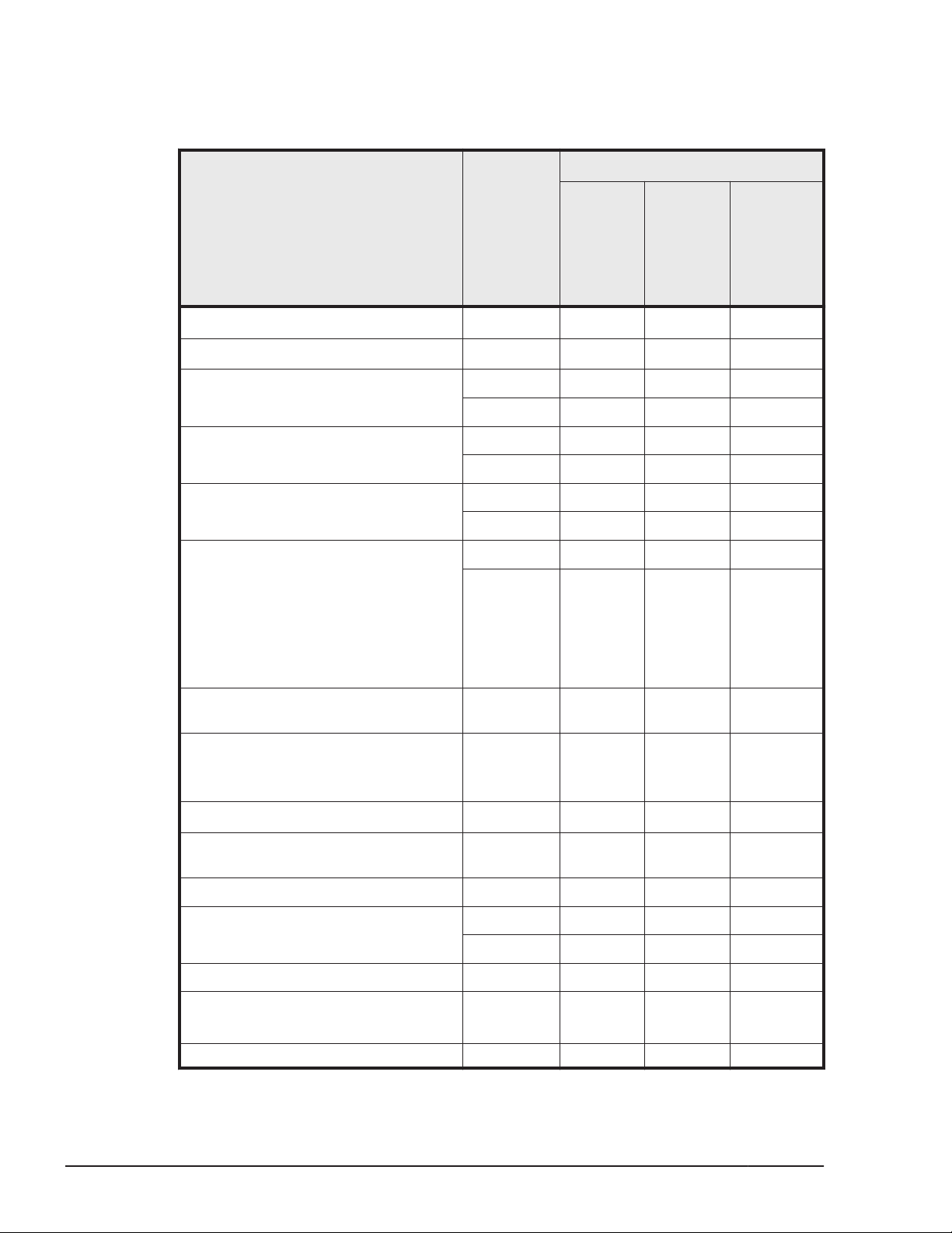
settings required for using HDLM, see the maintenance documentation for
storage systems.
Table 3-3 Supported Storage systems
OS
Windows
Supported storage systems
#1
Interface
Server
2003,
Windows
Server
2003 R2
EMC DMX series
EMC CX series
• Hitachi AMS series
• Hitachi WMS series
Hitachi AMS2000 series FC I/F Y Y Y
Hitachi SMS series FC I/F Y Y --
• Hitachi Universal Storage
Platform 100
• Hitachi Universal Storage
Platform 600
• Hitachi Universal Storage
Platform 1100
• Hitachi NSC 55
#2
#4
FC I/F
FC I/F
FC I/F Y Y --
iSCSI I/F Y Y --
iSCSI I/F Y Y Y
iSCSI I/F Y Y --
FC I/F Y Y --
iSCSI I/F Y -- --
#3 #6
Y
Y
#3
Windows
Server
2008,
Windows
Server
2008 R2
-- --
#7
Y
Windows
Server
2012,
Windows
Server
2012 R2
--
3-4
Hitachi Universal Storage Platform
V/VM
• Hitachi Virtual Storage Platform
• HP StorageWorks P9500 Disk
Array
HP EVA series
Hitachi Virtual Storage Platform
G1000
HP XP7 Storage FC I/F Y Y Y
HUS100 series FC I/F Y Y Y
HUS VM FC I/F Y Y Y
• XP128
• XP1024
• XP20000 FC I/F Y Y Y
#5
FC I/F Y Y Y
FC I/F Y Y Y
FC I/F
FC I/F Y Y Y
iSCSI I/F Y Y Y
FC I/F Y Y --
#3
Y
#8
Y
Creating an HDLM Environment
Hitachi Dynamic Link Manager (for Windows®) User Guide
--
Page 73

OS
Windows
Supported storage systems
• XP24000
Lightning 9900V series FC I/F Y Y --
• SVS
• XP10000
• XP12000
Thunder 9500V series FC I/F Y Y --
#1
Interface
iSCSI I/F Y -- --
FC I/F Y Y --
Server
2003,
Windows
Server
2003 R2
Windows
Server
2008,
Windows
Server
2008 R2
Windows
Server
2012,
Windows
Server
2012 R2
Legend:
Y: Usable
--: Not usable
FC I/F: FC Interface
iSCSI I/F: iSCSI Interface
#1
Dual controller configuration is required.
#2
The evaluation of EMC DMX3000 has been completed. Response to
inquiries for other systems of the EMC DMX series must be the same as
that of the EMC DMX3000. When using systems of the EMC DMX series
other than the EMC DMX3000, evaluate the connection in advance.
#3
For Windows Server 2003 (x86) or Windows Server 2003 (IPF), SP1 or
later must be installed.
#4
The evaluation of EMC CX700 has been completed. Response to inquiries
for other systems of the EMC CX series must be the same as that of the
EMC CX700. When using systems of the EMC CX series other than the
EMC CX700, evaluate the connection in advance.
Note that, for Windows Server 2003, EMC CX700 was used for
evaluations. For Windows Server 2008, EMC CX3-10 was used.
#5
The evaluation of HP EVA8000 has been completed. Response to inquiries
for other systems of the HP EVA series must be the same as that of the
HP EVA8000. When using HP EVA systems other than the HP EVA8000,
evaluate the connection in advance.
Creating an HDLM Environment
Hitachi Dynamic Link Manager (for Windows®) User Guide
3-5
Page 74

#6
Not supported for Windows Server 2003 (x64) or Windows Server 2003
R2 (x64).
#7
Supported only for Windows Server 2008.
#8
Supported only for EVA6400 storage systems running Windows Server
2008 R2 (x64).
HBAs
For details about the supported HBAs, see the HDLM Release Notes.
When Using Intermediate Volumes Managed by Hitachi RapidXchange to
Exchange Data
The following table lists the related programs for when intermediate volumes
managed by Hitachi RapidXchange are used to exchange data.
Table 3-4 Related Programs When Intermediate Volumes Managed by
Hitachi RapidXchange Are Used to Exchange Data
#1
OS
Windows Server 2003
(x86)
Windows Server 2003
(x64)
Windows Server 2003 R2
(x86)
Windows Server 2003 R2
(x64)
Windows Server 2003 R2
(x64) SP2
Windows Server 2008
(x86) SP2
Windows Server 2008 R2
(x64)
Related programs
File Access Library and File Conversion Utility (FAL/FCU)
01-03-64/21 or later
01-04-64/20 or later
File Access Library and File Conversion Utility (FAL/FCU)
01-04-65/21 or later
File Access Library and File Conversion Utility (FAL/FCU)
01-04-65/21 or later
File Access Library and File Conversion Utility (FAL/FCU)
01-04-65/21 or later
01-06-67/22 or later
File Access Library and File Conversion Utility (FAL/FCU)
01-05-66/25 or later
File Access Library and File Conversion Utility (FAL/FCU)
01-05-66/24 or later
File Access Library and File Conversion Utility (FAL/FCU)
01-04-65/24 or later
01-05-66/24 or later
01-07-68/00 or later
#2
#3
#3
#3
#3
#4
#5
#5
#3
#5
#6
3-6
#1
Creating an HDLM Environment
Hitachi Dynamic Link Manager (for Windows®) User Guide
Page 75

For details, see Supported OSs on page 3-2 in OSs Supported by HDLM
on page 3-2.
#2
Connection mainframe: MVS
Connection storage system: Lightning 9900V Series
#3
Connection mainframe: MVS
Connection storage system: Hitachi USP series
#4
Connection mainframe: MVS
Connection storage system: Hitachi Virtual Storage Platform
#5
Connection mainframe: MVS
Connection storage system: Hitachi Universal Storage Platform V
#6
Connection mainframe: MVS
Connection storage system: Hitachi Virtual Storage Platform G1000
For details about Hitachi RapidXchange, see the manual File Access Library &
File Conversion Utility for Solaris HP-UX AIX Windows Tru64 UNIX NCR SVR4
DYNIX/ptx Linux.
Cluster Software Supported by HDLM
The following table lists the supported cluster software for when you create a
cluster software configuration.
Creating an HDLM Environment
Hitachi Dynamic Link Manager (for Windows®) User Guide
3-7
Page 76

Table 3-5 Supported Cluster Software
OS SP
Cluster
software
name
Thunder 9500V
series,
Lightning
9900V series,
Hitachi USP
series, Hitachi
AMS2000/AMS
/WMS/SMS
series,
Universal
Storage
Platform V/VM
series, Virtual
Storage
Platform series,
and HUS VM
EMC
DMX
series
EMC
CX
series
HP
EVA
series
Windows Server
2003 (IPF)
Windows Server
2003 (x64)
#2
#2
No
service
pack
SP1 MSCS Y Y Y Y
SP2 MSCS Y Y Y Y
No
service
pack
SP2 MSCS Y -- Y Y
MSCS Y Y Y Y
VCS 5.0 Y -- -- --
Oracle RAC
#1
10g
VCS 5.0 Y -- -- --
Oracle RAC
#1
10g
MSCS Y -- Y Y
VCS 4.3 Y -- -- --
Oracle RAC
#1
10g
VCS 4.3 Y -- -- --
Oracle RAC
#1
10g
Y -- -- --
Y -- -- --
Y -- -- --
Y -- -- --
3-8
Windows Server
2003 R2 (x64)
Hitachi Dynamic Link Manager (for Windows®) User Guide
#2
Oracle RAC
#1
11g
No
service
pack
MSCS Y -- Y Y
VCS 4.3, 5.0 Y -- -- --
Oracle RAC
#1
10g
Creating an HDLM Environment
Y -- -- --
Y -- -- --
Page 77

OS SP
Cluster
software
name
Thunder 9500V
series,
Lightning
9900V series,
Hitachi USP
series, Hitachi
AMS2000/AMS
/WMS/SMS
series,
Universal
Storage
Platform V/VM
series, Virtual
Storage
Platform series,
and HUS VM
EMC
DMX
series
EMC
CX
series
HP
EVA
series
Windows Server
2003 (x86)
#2
Oracle RAC
#1
11g
SP2 MSCS Y -- Y Y
VCS 4.3, 5.0 Y -- -- --
Oracle RAC
#1
10g
Oracle RAC
#1
11g
No
service
pack
SP1 MSCS Y Y Y Y
MSCS Y Y Y Y
VCS 4.1, 4.2,
4.3
Oracle 9i
#1
RAC
Oracle RAC
#1
10g
VCS 4.3, 5.0 Y -- -- --
Oracle RAC
#1
10g
Y -- -- --
Y -- -- --
Y -- -- --
Y -- -- --
Y -- -- --
Y -- -- --
Y -- -- --
Oracle RAC
#1
11g
SP2 MSCS Y Y Y Y
VCS 4.3, 5.0 Y -- -- --
Oracle RAC
#1
10g
Oracle RAC
#1
11g
Y -- -- --
Y -- -- --
Y -- -- --
Creating an HDLM Environment
Hitachi Dynamic Link Manager (for Windows®) User Guide
3-9
Page 78

OS SP
Cluster
software
name
Thunder 9500V
series,
Lightning
9900V series,
Hitachi USP
series, Hitachi
AMS2000/AMS
/WMS/SMS
series,
Universal
Storage
Platform V/VM
series, Virtual
Storage
Platform series,
and HUS VM
EMC
DMX
series
EMC
CX
series
HP
EVA
series
Windows Server
2003 R2 (x86)
Windows Server
2008 (IPF)
No
#2
service
pack
SP2 MSCS Y Y Y Y
No
service
pack
SP2 MSCS Y -- Y --
MSCS Y Y Y Y
VCS 4.3, 5.0 Y -- -- --
Oracle RAC
#1
10g
Oracle RAC
#1
11g
VCS 4.3, 5.0,
5.1
Oracle 9i
#1
RAC
Oracle RAC
#1
10g
Oracle RAC
#1
11g
MSCS Y -- Y --
Y -- -- --
Y -- -- --
Y -- -- --
Y -- -- --
Y -- -- --
Y -- -- --
3-10
Windows Server
2008 R2 (IPF)
Windows Server
2008 (x64)
Hitachi Dynamic Link Manager (for Windows®) User Guide
No
service
pack
SP1 MSCS Y -- Y --
No
service
pack
MSCS Y -- Y --
MSCS Y -- Y --
Oracle RAC
#1
10g
Oracle RAC
#1
11g
Y -- -- --
Y -- -- --
Creating an HDLM Environment
Page 79

OS SP
SP2 MSCS Y -- Y --
Cluster
software
name
Thunder 9500V
series,
Lightning
9900V series,
Hitachi USP
series, Hitachi
AMS2000/AMS
/WMS/SMS
series,
Universal
Storage
Platform V/VM
series, Virtual
Storage
Platform series,
and HUS VM
EMC
DMX
series
EMC
CX
series
HP
EVA
series
Windows Server
2008 R2 (x64)
Windows Server
2008 (x86)
Oracle RAC
#1
11g
No
service
pack
SP1 MSCS Y -- Y --
No
service
pack
SP2 MSCS Y -- Y --
MSCS Y -- Y --
VCS 5.1 Y -- -- --
Oracle RAC
#1
10g
Oracle RAC
#1
11g
Oracle RAC
#1
10g
Oracle RAC
#1
11g
MSCS Y -- Y --
Oracle RAC
#1
10g
Oracle RAC
#1
11g
Y -- -- --
Y -- -- --
Y -- -- --
Y -- Y --
Y -- Y --
Y -- -- --
Y -- -- --
Windows Server
2012 (x64)
Windows Server
2012 R2 (x64)
Legend:
Y: Usable
Hitachi Dynamic Link Manager (for Windows®) User Guide
No
service
pack
No
service
pack
MSCS Y -- -- --
MSCS Y -- -- --
Creating an HDLM Environment
3-11
Page 80

--: Not usable
#1
For details about Oracle RAC versions, see the HDLM Release Notes.
#2
The following operating systems can manage the EMC DMX series, EMC
CX series, and HP EVA series:
- Windows Server 2003 (x86) SP1 or later
- Windows Server 2003 (IPF) SP1 or later
- Windows Server 2003 (x64)
Notes:
¢
When you use HDLM in a cluster configuration, you must install the
same version of HDLM on all the nodes that make up the cluster. If
different versions of HDLM are installed, the cluster system might not
operate correctly. If the HDLM Version and Service Pack
Version,which are displayed by executing the following command, are
the same, then the versions of HDLM will also be the same:
dlnkmgr view -sys -sfunc
¢
The DiskReservation agent of the VCS is not supported.
Volume Managers Supported by HDLM
The following table lists and describes the related programs for when a
volume manager is used.
Table 3-6 Related Programs When a Volume Manager Is Used
OS Related programs
Windows Server 2003 (IPF)
Windows Server 2003 (x64)
Windows Server 2003 (x86)
Windows Server 2008 R2(x64)
#
#
#
#
Veritas Storage Foundation for Windows 5.0
Veritas Storage Foundation for Windows 5.0
Veritas Storage Foundation for Windows 5.0
Veritas Storage Foundation for Windows 5.1
Veritas Storage Foundation for Windows 5.1
#
The EMC DMX Series, EMC CX Series and HP EVA Series do not support
volume managers.
Virtual Environments Supported by HDLM
3-12
HDLM supports the following virtualization environments:
Creating an HDLM Environment
Hitachi Dynamic Link Manager (for Windows®) User Guide
Page 81

• Logical partitioning feature available on Hitachi Compute Blade blade
servers
• Windows Server 2008 Hyper-V
• Windows Server 2012 Hyper-V
Memory and Disk Capacity Requirements
This section describes memory and disk capacity requirements.
Memory Requirements
The following table lists the memory requirements for a host.
Table 3-7 Memory Requirements for a Host
HDLM GUI OS Required memory
Not used Windows 40MB
Used Windows 65MB
Disk Requirements
The following table lists the disk capacity requirements for a host.
Table 3-8 Disk Space Requirements for a Host
Folder Disk capacity requirements
HDLM-installation-folder • When you use only the HDLM Core components:
10 MB + p MB
• When you install but do not use the HDLM GUI:
150 MB + p MB
• When you install and use the HDLM GUI:
150 MB + 20 MB + p MB
#1
#1
+ q MB
+ q MB
#2
+ 1 MB
#2
+ 1 MB
#1
+ q MB#2 + 1 MB
#1
This size depends on the log files settings. The maximum size is
30000MB.
When s is the error log file size (the default value is 9900) and m is the
number of error log files (the default value is 2), this value (p) can be
calculated as follows:
p = (s x m) / 1024 MB (rounded-up to the nearest integer)
#2
This size depends on the trace files settings. The maximum size is
1000MB.
When t is the trace file size (the default value is 1000) and n is the
number of trace files (the default value is 4), this value (q) can be
calculated as follows:
Creating an HDLM Environment
Hitachi Dynamic Link Manager (for Windows®) User Guide
3-13
Page 82

q = (t x n) / 1024 MB (rounded-up to the nearest integer)
Number of LUs and Paths That Are Supported in HDLM
The following table lists the number of LUs and paths supported in HDLM.
Table 3-9 Number of LUs and Paths Supported in HDLM
Item Number supported
Number of LUs 1 to 256
Number of paths per LU 1 to 12
Total number of paths 1 to 3060
Flow for Creating an HDLM Environment
Set up the environment to use HDLM as follows.
Figure 3-1 Flow of HDLM Environment Setup
HDLM Installation Types
This section describes the following types of HDLM installations: new
installation, upgrade installation, migration, and re-installation.
New installation of HDLM:
Installing HDLM on a server, which HDLM has never been installed on, is
called a new installation of HDLM.
Upgrade installation of HDLM:
Installing a newer version of HDLM over the existing version without
removing the existing version is called an upgrade installation of
HDLM.You can perform an upgrade installation for only HDLM 5.5 or later.
3-14
Hitachi Dynamic Link Manager (for Windows®) User Guide
Creating an HDLM Environment
Page 83

Migration of HDLM:
Installing HDLM 5.5 or later after removing HDLM 5.4 or earlier is called a
migration of HDLM. By doing this, you can keep the settings from the
previous version.
Re-installation of HDLM:
Installing the same version of HDLM, in order to restore the existing
version, without first removing that version is called a re-installation of
HDLM.
When installing HDLM, you can select either of the following modes for
installing the HDLM programs you want:
• HDLM Core components
Install all HDLM programs except for HDLM GUI and Hitachi Command
Suite Common Agent Component.
• All HDLM components
Install all HDLM programs.
Notes on Creating an HDLM Environment
This section provides notes on creating an HDLM environment.
For details about operating HDLM, see
Notes on HBAs and HBA Drivers
• If you are using the Storport Miniport driver as an HBA driver in Windows
Server 2003, install QFE 838894 or later for the Microsoft Storport driver
or install Windows Server 2003 SP1 or later, before installing HDLM.
• If you are using multiple HBAs, make sure that the models of the HBAs
are the same. Also make sure that the HBA firmware versions and driver
versions are the same.
Notes on Storage systems
• You must not change the vendor ID and product ID of the storage
system. If you change these IDs, HDLM will not be able to recognize the
storage system.
• If the host and the storage system are connected via a Fibre Channel
switch, select Point To Point as the connection type. If you select FC-AL
(Fibre Channel Arbitrated Loop) as the connection type, an unexpected
path error might occur.
• Windows can recognize LUNs from 0 to 255. Therefore, set LUNs within
the range from 0 to 255 in the storage system management software.
Notes on Using HDLM on page 4-2.
Creating an HDLM Environment
Hitachi Dynamic Link Manager (for Windows®) User Guide
3-15
Page 84

Notes on HDLM Versions
• If HDLM 5.4 or earlier has been installed, remove HDLM first and then
proceed with a new installation of HDLM by following the procedure
described in Migrating from HDLM 5.4 or Earlier to HDLM 5.5 or Later on
page 3-66.
• For HDLM 5.6 or later, the trace files for HDLM versions earlier than 5.6
are divided into integrated trace files and trace files. The logs for the
HDLM commands and HDLM GUI operations are output to integrated trace
files. Trace information for the HDLM manager is output to trace files. The
output destinations for the files are changed as follows:
¢
When you migrate from an HDLM version earlier than 04-00 to an
HDLM version 5.6 or later
- Trace files before migration:
drive-for-program-installation:\Program Files#\HITACHI\HNTRLib
\spool\hntrn.log
(n indicates a file number)
- Integrated trace files after migration:
drive-for-program-installation:\Program Files#\HITACHI
\HNTRLib2\spool\hntr2n.log
(n indicates a file number)
- Trace files after migration:
drive-for-program-installation:
\DynamicLinkManager\log\hdlmtrn.log
(n indicates a file number)
The underlined part indicates the folder specified during installation.
¢
When you migrate from HDLM versions 04-01 to 5.5 to HDLM version
5.6 or later, or when you perform an upgrade installation from HDLM
5.5 or later
- Trace files before migration or upgrade:
drive-for-program-installation:\Program Files#\HITACHI\HNTRLib
\spool\hntrn.log
(n indicates a file number)
- Integrated trace files after migration or upgrade:
drive-for-program-installation:\Program Files#\HITACHI
\HNTRLib2\spool\hntr2n.log
(n indicates a file number)
- Trace files after migration or upgrade:
drive-for-program-installation:
\DynamicLinkManager\log\hdlmtrn.log
(n indicates a file number)
The underlined part indicates the folder specified during installation.
\Program Files\HITACHI
\Program Files\HITACHI
3-16
#
For Windows Server2003 (excluding the x86 edition) , Windows
Server 2008 (excluding the x86 edition) , or Windows Server 2012 ,
Program Files is Program Files (x86).
Creating an HDLM Environment
Hitachi Dynamic Link Manager (for Windows®) User Guide
Page 85

• Before installing or upgrading HDLM 5.5 or later, make sure that no other
application is using an HDLM management-target LU.
• When HDLM 5.5 or later is installed for the first time, the event described
below will occur and is output to the event log. However, it does not
affect the system or HDLM operations.
Description
Event provider attempted to register query "select * from
WMIEvent" whose target class "WMIEvent" does not exist. The
query will be ignored.
• When you use HDLM in a cluster configuration, you must install the same
version of HDLM on all the nodes that make up the cluster. If different
versions of HDLM are installed, the cluster system might not operate
correctly. If the HDLM Version and Service Pack Version, which are
displayed by executing the following command, are the same, then the
versions of HDLM will also be the same:
dlnkmgr view -sys -sfunc
Notes on Windows
• We recommend that you install Windows and HDLM on an internal host
disk. If you install them on an HDLM management-target disk, the
following problems might occur:
¢
You might not be able to store the OS crash-dump and error
information on the disk.
¢
After removing HDLM, some files might not be deleted correctly.
• When restoring a Windows system disk from a backup, restore the disk to
a single-path configuration.
After restoring the disk, confirm that HDLM is running properly, and then
change to a multi-path configuration.
• If the size of the Path system environment variable is 1024 bytes or
more, the HDLM manager might not be able to start. When the HDLM
manager fails to start, the following message is output to the Windows
event log (system):
Source: Service Control Manager
Type: Error
Event ID: 7000
Description: DLMManager service could not be started for the
following reason: The service did not respond to the start
request or control request within the specified period.
If the HDLM manager fails to start, delete all unnecessary character
strings in the path so that the size of the Path system environment
variable is 1024 bytes or less:
Creating an HDLM Environment
Hitachi Dynamic Link Manager (for Windows®) User Guide
3-17
Page 86

For Windows Server 2003 (excluding the x86 edition) , Windows Server
2008 (excluding the x86 edition) , or Windows Server 2012:
Windows-installation-drive:\Program Files (x86)\Common Files
\Hitachi
Windows-installation-drive:\Program Files (x86)\HDVM\HBaseAgent
\bin
Windows-installation-drive:\Program Files (x86)\HDVM\HBaseAgent
\util\bin
HDLM-installation-folder\bin
HDLM-installation-folder\lib
For other versions of Windows:
Windows-installation-drive:\Program Files\Common Files\Hitachi
Windows-installation-drive:\Program Files\HDVM\HBaseAgent\bin
Windows-installation-drive:\Program Files\HDVM\HBaseAgent\util
\bin
HDLM-installation-folder\bin
HDLM-installation-folder\lib
For Windows Server 2003 SP1 and Windows Server 2003 R2 (with no
service pack), if you do not want to use one of the above methods, you
can use a Microsoft hotfix to start the HDLM manager. For details about
how to obtain and use the hotfix and how it will affect the system, contact
Microsoft.
• HDLM uses the Windows Installer service. Therefore, when you install
HDLM, take the following precautions:
a. In the Startup Type setting for the Windows Installer service, specify
Manual or Automatic.
b. Before installing HDLM, make sure that no other programs are using
the Windows Installer service.
If you install HDLM while the Startup Type setting for the Windows
Installer service is disabled or while another program is using the
Windows Installer service, the following message will appear and the
installation might fail:
KAPL09034-E An Internal error occurred in the HDLM Installer.
Code = -99 nnnnn
If this message appears during a new installation of HDLM:
Confirm that conditions 1 and 2 above are met, and then install HDLM
again.
If this message appears during an upgrade or re-installation of HDLM:
Confirm that conditions 1 and 2 above are met, and then re-attempt
an upgrade or re-installation of HDLM.
Be aware that even though an upgrade or re-installation of HDLM
failed, the Add/Remove Programs window might indicate that HDLM
has been installed normally.
3-18
Creating an HDLM Environment
Hitachi Dynamic Link Manager (for Windows®) User Guide
Page 87

• If you install HDLM when either of the following conditions exists, an error
might be displayed for the mirror disk in the Disk Management window of
Windows.
¢
A mirror disk volume that uses a Windows dynamic disk exists among
the HDLM management-target devices
¢
An application that uses the dmaadmin service is being executed.
This error does not affect the data on the HDLM management-target
devices. If you restart the host and then activate the disk in the Disk
Management window of Windows, this error will not appear. To prevent
this error from occurring, perform the following before installing HDLM:
¢
When a mirror disk volume that uses a dynamic disk exists among the
HDLM management-target devices
Close the management console for the disk.
¢
When the application that uses the dmaadmin service is being
executed
Stop the application that uses the dmaadmin service.
• In Windows Server 2003 (excluding IPF versions) , Windows Server 2008
(excluding IPF versions) and Windows Server 2012 , boot disk
environments that use the GUID Partition Table (GPT) are not supported.
• In Windows Server 2003 (excluding x86 versions) , Windows Server 2008
(excluding x86 versions) and Windows Server 2012, we recommend that
you install HDLM in a folder other than Program Files.
• When installing HDLM, the name of the HDLM installation folder and the
names of all its parent folders must satisfy all of the following conditions:
¢
The name must not be a reserved name specified in Windows.
Reserved names include names like CON, AUX, COM1 to COM9, LPT1 to
LPT9, PRN, and NUL.
¢
The name must be made by using only the following characters:
A - Z, a - z, 0 - 9, -, _, ., @, or a single byte space
¢
The last character cannot be a single byte space.
¢
The name cannot contain two or more single byte spaces in a row.
If you attempt to install HDLM in a folder that does not satisfy these
conditions, problems such as those described in the table below might
occur. If this happens, reinstall HDLM by following the procedures given
below.
Table 3-10 Problems and What to Do When Specifying a Folder That
Does Not Satisfy the Conditions for an HDLM Installation
Problem What to do
An internal error occurred and the
installation was interrupted.
Specify a folder that satisfies the above
conditions and re-install the HDLM.
After the installation has finished, the
error information could not be collected
Remove HDLM, and then re-install it by
specifying a folder that satisfies the
above conditions.
Creating an HDLM Environment
Hitachi Dynamic Link Manager (for Windows®) User Guide
3-19
Page 88

Problem What to do
when the DLMgetras utility for collecting
HDLM error information was executed.
• When installing HDLM in Windows Server 2008 or Windows Server 2012,
perform the following operation before the installation to make sure
applications cannot access the HDLM management-target disks.
¢
If the disk is not used as a cluster resource:
In the Windows' Disk Management windows, offline the disk.
¢
If the disk is used as a cluster resource:
Stop Cluster Service.
• Windows Server 2008 or Windows Server 2012 supports user account
control (UAC). If you are logged on with a non-administrator account, use
the Administrator: Command Prompt window when executing any of
the following programs to install or remove HDLM:
¢
setup.exe
¢
installhdlm (installhdlm utility)
¢
removehdlm (removehdlm utility)
#
#
This program can also be executed using Run as administrator.
• If you are using Hyper-V in Windows Server 2008, you cannot use HDLM
on a guest OS. Install HDLM on a host OS.
If you want to install or remove HDLM on a host OS, first terminate the
Hyper-V manager console. If the Hyper-V manager console is running,
the installation or removal of HDLM will stop. If this happens, you can
continue with the installation or removal of HDLM by first terminating the
Hyper-V manager console.
• If you are using Hyper-V in Windows Server 2008, you cannot use a
cluster environment on a guest OS.
• If you are using Hyper-V, unallocate the physical hard disk of an HDLM
management-target device that you have allocated to a guest OS before
you perform an installation, upgrade installation, or removal of HDLM on a
host OS. Then, after the installation, upgrade installation or removal of
HDLM on the host OS, allocate the physical hard disk to the guest OS
again.
Notes on Related Software
• Do not install any multi-path management software other than HDLM. If
multi-path management software other than HDLM has been installed on
the host, remove the software, and then restart the host before reinstalling HDLM.
• You cannot use HDLM for Windows and HDLM for VMware on the same
host.
3-20
Hitachi Dynamic Link Manager (for Windows®) User Guide
Creating an HDLM Environment
Page 89

• HDLM uses the following MPIO drivers according to the host OS:
¢
In Windows Server 2003
HDLM uses the MPIO driver on the HDLM DVD that is installed during
HDLM installation. The MPIO driver consists of the following files:
mpio.sys, mpspfltr.sys, mpdev.sys.
¢
In Windows Server 2008 , or Windows Server 2012
HDLM uses the MPIO driver already installed with the OS, not the
MPIO driver on the HDLM installation DVD.
• If you attempt to install HDLM on a Windows Server 2003 host on which
an MPIO driver has already been installed, and the MPIO driver version
differs from that of the driver bundled with HDLM, the KAPL09127-W
message is output. This message asks whether it is OK to overwrite the
existing MPIO driver. If you are upgrading HDLM, continue the
installation. If any multi-path management software other than HDLM
exists on the host, cancel the installation, and then remove the software.
• If you install HDLM, the KAPL09257-W or KAPL09258-E message might
appear. If either of the messages appears, the version of the MPIO driver
on the host is later than the one bundled with HDLM. Also, if you install a
piece of multi-path management software other than HDLM, the MPIO
driver might be installed. In this case, delete the setup information files
for the installed MPIO driver, and then reinstall HDLM. The MPIO driver
setup information is defined in the files mpio.inf and mpdev.inf. When
an MPIO driver is installed, these files are renamed to oemn.inf (where n
represents a number), and then registered in the following folder:
Windows-installation-folder\inf. In addition, two other oemn.pnf files will
also be created in this folder.
If either the KAPL09257-W or the KAPL09258-E message appears,
perform the following procedure to delete the two oemn.inf files and two
oemn.pnf files:
a. Check the MPIO driver version indicated in the KAPL09257-W or the
KAPL09258-E message.
In this example, the MPIO driver version is n.nn.nnnn.nnnn (n
represents numbers):
KAPL09257-W HDLM cannot be installed on a system where MPIO
n.nn.nnnn.nnnn has already been installed.
b. Find the setup information files (which have the file extension inf)
that contain the version number information, by using the Windows
search function in the following folder:
Windows-installation-folder\inf
There will be two oemn.inf files.
c. Make sure that the contents of the oemn.inf files you have found are
identical to the files mpio.inf and mpdev.inf for the MPIO driver that
is installed on the host.
If you have removed HDLM and then install an earlier version of
HDLM, check the mpio.inf and mpdev.inf files on the DVD for the
later version of HDLM.
Creating an HDLM Environment
Hitachi Dynamic Link Manager (for Windows®) User Guide
3-21
Page 90

d. Delete the setup information files from the following folder:
Windows-installation-folder\inf
If there are any files whose names are the same as the setup
information files but have the extension pnf, you also need to delete
these files.
Note that we strongly recommend that, before deleting any setup
information files, you first back up the files and store the backup files
in a different folder.
¢
If you are installing HDLM on Windows Server 2008 or Windows
Server 2012, do not delete the multi-path I/O feature from the Server
Manager.
• When a host is connected to an Oracle RAC voting disk via multiple paths,
if an I/O timeout occurs for any one of these paths, HDLM will perform a
failover.
Note that, depending on the Oracle RAC settings, Oracle RAC might
determine that a node error has occurred before the failover has
completed, upon which it will re-configure the cluster.
If HDLM is managing the paths that are connected to an Oracle RAC
voting disk, change the following settings to be compatible with your
version of Oracle RAC:
¢
When using Oracle RAC 10g 10.1.0.3.0 or later or Oracle RAC 11g:
Change the value of MISSCOUNT to match the storage system type.
Use the following table to determine a value, and then change the
current value to a value equal to or greater than the value you have
determined.
Table 3-11 Formula for Calculating MISSCOUNT
Storage system type
• Lightning 9900V series
• Hitachi USP series
• Universal Storage
Platform V/VM series
• Virtual Storage Platform
series
• VSP G1000 series
• HUS VM
• Hitachi
AMS2000/AMS/WMS/SMS
series
• HUS100 series
• Thunder 9500V series
¢
When using Oracle RAC 10g 10.2.0.2.0 or later or Oracle RAC 11g:
Formula for obtaining the value of
MISSCOUNT
number-of-paths-connected-to-the-voting-disk
x 60 seconds
number-of-paths-connected-to-the-voting-disk
x 30 seconds
In addition to the value of MISSCOUNT shown above, also change the
value of DISKTIMEOUT. As with MISSCOUNT, the value of DISKTIMEOUT
3-22
Creating an HDLM Environment
Hitachi Dynamic Link Manager (for Windows®) User Guide
Page 91

is different for each type of storage system. Use the following table to
determine a value, and then change the current value to a value equal
to or greater than the value you have determined.
Table 3-12 Formula for Calculating DISKTIMEOUT
Number
of paths
Storage system type
connecte
d to the
voting
disk
Formula for obtaining the value
of DISKTIMEOUT
• Lightning 9900V series
• Hitachi USP series
• Universal Storage
Platform V/VM series
• Virtual Storage Platform
series
• VSP G1000 series
• HUS VM
• Hitachi
AMS2000/AMS/WMS/SMS
series
• HUS100 series
• Thunder 9500V series
3 or less You do not need to change the value
of DISKTIMEOUT.
4 or more number-of-paths-connected-to-the-
voting-disk x 60 seconds
6 or less You do not need to change the value
of DISKTIMEOUT.
7 or more number-of-paths-connected-to-the-
voting-disk x 30 seconds
For details on how to change MISSCOUNT and DISKTIMEOUT, contact the
company with which you have an Oracle Support Services contract.
Note that when you remove HDLM from the above configuration, you
must reset the values of MISSCOUNT and DISKTIMEOUT to their original
values. Therefore, make a note of the original values of MISSCOUNT and
DISKTIMEOUT before changing them.
• Configurations in which Oracle RAC is installed in Oracle Cluster File
System are not supported.
• If you install HDLM while resident software (such as antivirus software) is
running, HDLM might not operate correctly. Before installing HDLM, make
sure that you have stopped all software programs, including all resident
software.
Notes on New Installations and Upgrade Installations
• When installing HDLM, use only one cable to connect the host to the
storage system until instructed otherwise in the procedure in section
Performing a New Installation of HDLM on Windows Server 2003 on page
3-29, or Performing a New Installation of HDLM on Windows Server 2008
and Windows Server 2012 on page 3-52. If the host is restarted while it
is connected to the storage system via multiple paths at a time other than
those indicated in the procedure in section
of HDLM on Windows Server 2003 on page 3-29, or Performing a New
Creating an HDLM Environment
Hitachi Dynamic Link Manager (for Windows®) User Guide
Performing a New Installation
3-23
Page 92

Installation of HDLM on Windows Server 2008 and Windows Server 2012
on page 3-52, the contents of the disk might become corrupted.Note
that you can upgrade or re-install HDLM in a multipath configuration in
Windows Server 2003 SP1 or later , in Windows Server 2008 and in
Windows Server 2012.
• HDLM does not support multiple-path configurations in which both an FCSAN and IP-SAN exist on the same LU.
• If you install HDLM for the first time, or perform an upgrade installation of
HDLM after the license has expired, a license key is necessary. To update
the HDLM license, execute the dlnkmgr command's set-lic operation.
The expiration date of the license key is determined by the license key
specified in the license key file or the input license key type. For
information on license key types and the set operation, see
set (Sets Up
the Operating Environment) on page 6-16 .
• Installing HDLM requires 70 MB of unused capacity on the system drive.
• Terminate all programs that are running before installing HDLM.
• If you select a folder for the HDLM installation folder, and then suddenly
decide to change the folder for the installation folder, the first folder that
you selected might be created along with the actual folder you want to
use for the installation folder. Delete the created folder because a folder
other than the last selected folder is not necessary.
• Depending on the environment, installing HDLM might take a while to
finish. Do not terminate the installation process while a progress bar for
installation is displayed. The following is an approximate calculation of the
time required for installation:
(5 x number-of-connected paths) seconds
• If installation of HDLM terminates abnormally and the KAPL09016-E
message is output, check whether an HDLM version from another OS has
been installed on the same drive.
3-24
¢
When an HDLM version from another OS has been installed:
Remove the version of HDLM that is already installed, and then rerun
the installation program.
¢
When HDLM for another OS has not been installed:
Perform the installation again by following the procedure below:
a. From Explorer, in the Tools menu, choose Folder Options.
The Folder Options window is displayed.
b. Click the View tab, and in the Advanced settings field, under
Hidden files and folders, select Show hidden files and folders.
c. Delete the following folder:
OS-installation-drive:\Program Files#\InstallShield
\InstallationInformation\
{DFF378A1-240E-11D5-8A43-0000E2382F13}
#
Creating an HDLM Environment
Hitachi Dynamic Link Manager (for Windows®) User Guide
Page 93

For Windows Server 2003 (excluding the x86 edition) , Windows
Server 2008 (excluding the x86 edition) or Windows Server 2012,
Program Files is Program Files (x86).
d. Restore the setting for Show hidden files and folders that you
changed in step b.
e. Rerun the HDLM installation program.
• When installing HDLM on a host where a Device Manager agent 5.0 or
later is installed, do not execute any of the following Device Manager
agent commands during the installation of HDLM:
hbsasrv, HiScan, hdvmagt_account, hdvmagt_schedule, hldutil, TIC
• If you want to install only the HDLM Core components, perform an
unattended installation of HDLM. For details about how to perform an
unattended installation, see
page 7-17.
• After all HDLM components have been installed on a host, if you want to
create a configuration that uses only the HDLM Core components, you
cannot do so by performing an upgrade installation or re-installation. To
re-configure HDLM with only the HDLM Core components, first remove
HDLM, and then perform an unattended new installation of HDLM.
• If you want to link HDLM to other Hitachi Command Suite products, you
need to install all the HDLM components, not just the HDLM Core
components.
• In Windows Server 2003 SP1 or later, if you change an HDLM
management-target device during an upgrade installation and then
restart the host, the KAPL08019-E and KAPL08022-E messages might be
output, and the path status might change to Offline(E) or Online(E). If
this happens, execute the dlnkmgr command's online operation to
change the path status to Online.
The installhdlm Utility for Installing HDLM on
Notes on Migration or Upgrade Installation
If either of the following conditions is met, the disk numbers managed by
Windows might be changed from the state they were in prior to a migration
installation or upgrade installation:
• The disk numbers managed by Windows are non-consecutive and an
HDLM version earlier than 5.4 is migrated to 5.5 or later
• Hitachi's RAID Manager command device is used and an HDLM version
earlier than 5.7 is migrated or upgraded to 5.7.1 or later
If a disk number is changed while the disk is being used by an application,
perform the following:
If the disk number can be changed:
Change the disk number to the number that will be used after the
change.
If the disk number cannot be changed:
Creating an HDLM Environment
Hitachi Dynamic Link Manager (for Windows®) User Guide
3-25
Page 94

Restore the disk number managed by Windows to the number that was in
use prior to the migration installation or upgrade installation. For details
about how to do this, contact Microsoft.
Installing HDLM
First, check whether HDLM has been installed on the host.
When HDLM has already been installed on the host:
You can upgrade HDLM by performing an update installation as described
in Upgrade Installation or Re-installation of HDLM on page 3-64 or
Migrating from HDLM 5.4 or Earlier to HDLM 5.5 or Later on page 3-66.
When you install HDLM, Hitachi Network Objectplaza Trace Library will also be
installed. The file path of the Hitachi Network Objectplaza Trace Library
integrated trace information file is installation-destination-drive:\Program
Files#\HITACHI\HNTRLib2\spool\Hntr2n.log, where n is the number of the
integrated trace information file.
#
For Windows Server 2003 (excluding the x86 edition) , Windows Server
2008 (excluding the x86 edition) , or Windows Server 2012, Program
Files is Program Files (x86).
Follow the procedure explained here to install HDLM, even in cases where the
boot disk is an HDLM-managed device.
Preparations for a New Installation of HDLM
The following explains what you need to do before performing a new
installation of HDLM.
For an FC connection, check the topology (Fabric, AL, etc.) and perform an
appropriate setup.
To prepare for an HDLM installation:
1. Use a single cable to connect the host to the storage system.
Using multiple paths to connect a host to a storage system before
installing HDLM might result in unstable Windows operations. Make sure
that you only use a single-path configuration until the HDLM installation is
done.
The following figure shows a single path configuration and a multi-path
configuration.
3-26
Creating an HDLM Environment
Hitachi Dynamic Link Manager (for Windows®) User Guide
Page 95

Figure 3-2 Single Path Configuration and Multi-path Configuration
2. Set up the storage system.
Assign an LU to each port.
To change the settings of a storage system, follow the maintenance
documentation for that particular storage system.
3. Install the HBAs onto the host.
Install as many HBAs as you want to use.
In a cluster configuration, make sure that the manufacturer and model of
the HBA is the same for all the hosts that make up the cluster. Also, make
sure that the versions of the HBA micro-programs are the same.
4. Set up the switches.
For details on how to set up a switch, see the documentation for the
particular switch. This step is unnecessary if you do not use a switch.
5. Set up the BIOS for the HBAs.
Set up the BIOS for all the HBAs, regardless of whether paths exist.
Different settings are used for different topologies. For details on how to
set up the BIOS, see the HBA documentation.
6. Install Windows, and any non-HDLM drivers.
Install Windows and any non-HDLM drivers by following the
documentation for each of the products.
7. Set up the HBAs.
See the HBA documentation and manual to complete the required setup.
8. If your configuration uses an IP-SAN, install and set up the iSCSI initiator
(iSCSI software or HBA).
For details, see the iSCSI initiator documentation, the documentation for
the HBA, or the storage system documentation.
9. Prepare the LUs.
For each LU that you want to use, be sure to write signatures, create
partitions, and then format them. Because the system is still in the single
path configuration, no problems will occur even if you write a signature
for each LU.
Creating an HDLM Environment
Hitachi Dynamic Link Manager (for Windows®) User Guide
3-27
Page 96

10. Restart the host.
11. Confirm that the host is operating normally.
Preparations for Installing HDLM by Performing an Unattended Installation
An unattended installation allows a user to install HDLM without having to
enter information into dialog boxes or specify HDLM functions. Instead, the
user defines the required information for the dialog boxes in an installationinformation settings file prior to running the installation. The procedure for an
unattended installation is as follows:
1. Specify the required information for the installation in the installationinformation settings file.
2. Execute the installhdlm utility.
3. Information will be automatically entered into the dialog boxes or HDLM
functions, as defined in the installation-information settings file.
4. The installation will finish and log data will be output, showing the status
and result of the installation.
This section describes the following aspects of an unattended installation:
• How to create an installation-information settings file
• Notes on installation
For details on the installhdlm utility, see
HDLM on page 7-17.
For details about performing an unattended installation, see
New Installation of HDLM on Windows Server 2003 on page 3-29 or
Performing a New Installation of HDLM on Windows Server 2008 and
Windows Server 2012 on page 3-52.
The installhdlm Utility for Installing
How to Create an Installation-Information Settings File
For an installation-information settings file, you need to define the license key
file name, installation destination folder, and then any other information that
is required for the particular installation.
HDLM provides a sample file in order to simplify the editing process of an
installation-information settings file. The sample file is located on the supplied
DVD.
To edit the installation-information settings file:
1. Copy the sample file for the installation-information settings file to any
folder.
The location of the sample file is as follows:
drive-to-which-the-installation-DVD-is-inserted:\HDLM_Windows
\DLMTools\sample_installhdlm.ini
Performing a
3-28
Creating an HDLM Environment
Hitachi Dynamic Link Manager (for Windows®) User Guide
Page 97

2. Use a text editor to edit the sample file that was copied in step 1, in order
to create an installation-information settings file for your particular
configuration.
Items that need to be defined in the installation-information settings file
are described in Contents of an Installation-Information Settings File on
page 7-18 below.
Notes on an Unattended Installation
• Do not forcibly stop the execution of the installhdlm utility during an
unattended installation of HDLM. Even if you forcibly stop the execution of
the installhdlm utility, the HDLM installation will not be stopped. If you
have specified y for the restart key in the installation-information
settings file, the computer will restart after the installation finishes
successfully. Make sure that you check the results of the installation in
installhdlm.log, if you had to forcibly stop the execution of the
installhdlm utility.
• The disk capacity necessary for the execution of the installhdlm utility is
as follows:
A folder specified in the workdir key (if the workdir key has not been
specified, a folder specified in the TMP or TEMP environment variable)
must have at least 20 KB of free disk capacity.
• Information for the HDLM operation can also be specified by using the
HDLM command's set operation. To specify the information by using this
way, see
untended installation is completed.
For details about what can be defined in a installation-information settings
file, see
7-18.
For details about the set operation of the HDLM command, see set (Sets
Up the Operating Environment) on page 6-16.
Setting Up HDLM on page 3-71 and make sure that an
Contents of an Installation-Information Settings File on page
Performing a New Installation of HDLM on Windows Server 2003
In a Non-Cluster Environment
Before installing HDLM, have a license key ready.
If you want to perform an unattended installation, also be sure to prepare an
installation-information settings file.
To install HDLM on a host that does not currently have HDLM installed
on it:
1. Log on to Windows as a member of the Administrators group.
2. Save the license key file directly under the Windows installationdestination drive.
installation-drive:\hdlm_license
Creating an HDLM Environment
Hitachi Dynamic Link Manager (for Windows®) User Guide
3-29
Page 98

The license key file will be deleted after the installation finishes.
3. Perform the installation.
¢
If you are not performing an unattended installation, insert the DVD
into the drive.
In the displayed window, click the Install button next to for
Windows of Hitachi Dynamic Link Manager.
If no window is displayed, manually run the installer (setup.exe).
The program checks whether HDLM has already been installed. If
HDLM 5.4 or earlier has been installed, the KAPL09129-E message will
appear. If this happens, carry out the procedure shown in
from HDLM 5.4 or Earlier to HDLM 5.5 or Later on page 3-66. If
HDLM 5.5 or later has been installed, the KAPL09173-W message will
appear. If this happens, carry out the procedure shown in Upgrade
Installation or Re-installation of HDLM on page 3-64. If no message
appears, go to step 4.
¢
If you are planning to perform an unattended installation, execute the
installhdlm utility.
At the command prompt, execute the following command:
drive-to-which-the-installation-DVD-is-inserted:\HDLM_Windows
\DLMTools\installhdlm -f installation-information-settings-
file
Migrating
This command checks whether HDLM has already been installed. If
HDLM 5.4 or earlier has been installed, the KAPL09129-E message will
appear. If this happens, carry out the procedure shown in
Migrating
from HDLM 5.4 or Earlier to HDLM 5.5 or Later on page 3-66. If
HDLM 5.5 or later has been installed, the KAPL09183-E message will
appear, and then the upgrade installation or re-installation will be
performed.
If you have specified n for the restart key in the installationinformation settings file, go to step 11.
If you have specified y for the restart key in the installationinformation settings file, go to step 16.
4. The program checks the MPIO driver version, and then installs the MPIO
driver. If a message appears, asking you whether you want to install the
MPIO driver, make sure that no multi-path management software other
than HDLM is installed.
¢
If multi-path management software other than HDLM is installed, click
the Cancel button to cancel the installation, remove the multi-path
management software, and then install HDLM.
¢
If no multi-path management software other than HDLM is installed,
click the Next button to continue the installation.
5. Follow the instructions shown in the messages that appear in the window.
3-30
¢
If a license key file was saved in step 2, specify that license key file.
¢
If a license key file is not being used, specify the license key directly.
Creating an HDLM Environment
Hitachi Dynamic Link Manager (for Windows®) User Guide
Page 99

6. Specify the installation folder by following the instructions shown in the
messages that appear in the window.
The utility for registering HDLM persistent reservation keys (dlmprsvkey)
will be automatically executed. However, creation of the PRSV key might
be unsuccessful if, for example, an NIC does not exist. If the PRSV key is
created with time information only, or if key creation fails, a dialog box
will prompt you to enter a PRSV key.
If this dialog box appears, go to step 7; otherwise, go to step 9.
7. Enter the PRSV key by following the instructions shown in the dialog box.
The PRSV key is required for the HDLM functions to properly operate.
Also, the value of the PRSV key must be unique for each host.
8. If the KAPL09128-W message appears, you will need to re-enter a correct
PRSV key.
If a message does not appear, go to the next step.
9. Select an HDLM management-target device only when the OS is one of
the following:
¢
Windows Server 2003 (x86) SP1 or later
¢
Windows Server 2003 (IPF) SP1 or later
¢
Windows Server 2003 (x64)
#
#
This OS cannot be used with the EMC DMX series.
The Hitachi storage systems and HP StorageWorks XP Series option
is always selected. To select an EMC DMX series or EMC CX series LU as
the HDLM management-target device, select EMC Symmetrix DMX
Series, CLARiiON CX Series. To select an HP EVA series LU as the
HDLM management-target device, select HP StorageWorks EVA Series.
10. Follow the instructions shown in the messages that appear in the window.
¢
If a dialog box with the following text appears during installation, and
the Storport Miniport driver is being used as the HBA driver, stop the
HDLM installation. After that, install QFE838894 or a later version of
the Microsoft Storport driver, or install Windows Server 2003 SP1 or
later.
Notes on using a Storport Miniport driver
Read these notes before using a Storport Miniport driver as an
HBA driver.
The file version of the Storport.sys of this system
(Microsoft(R) Storport driver) is n.n.nnnn.n.
When using a Storport Miniport driver as an HBA driver:
Please update the Storport Miniport driver to a Storport.sys
with a file version n.n.nnnn.n or later.
¢
The PRSV key will be registered before the installation finishes. If the
KAPL09131-W message appears, follow the procedure described in
step 12.
¢
Although a message prompting you to restart the host appears after
the installation has finished, a restart is not necessary.
Creating an HDLM Environment
Hitachi Dynamic Link Manager (for Windows®) User Guide
3-31
Page 100

¢
In the last installation window, the following message might be
output:
When you manage a host by using Global Link Manager and
Windows firewall is enabled on that host, execute the
firewall_setup command to allow a firewall exception.
If Global Link Manager will not be used to manage HDLM, you do not
need to take any action.
To manage HDLM with Global Link Manager, register Firewall
exceptions. For details, see
Firewall Settings for Managing HDLM by
Using Global Link Manager on page 3-68.
11. Check the results of the installation.
If you have performed an unattended installation, check the installation
results from the command prompt.
12. After the installation finishes, execute the dlmprsvkey utility with the -v
parameter specified.
Execute the following command:
HDLM-installation-folder\bin\dlmprsvkey -v
Make sure that the PRSV key displayed by the dlmprsvkey utility is
unique among all the other hosts in the SAN. If the PRSV key is not
unique or is not registered, or if the KAPL09131-W message appears,
execute the dlmprsvkey utility with the -r parameter specified to reregister the PRSV key. If the PRSV key is not registered, the HDLM
functions might not properly operate. For details about the dlmprsvkey
utility, see The dlmprsvkey Utility for Registering an HDLM Persistent
Reservation Key on page 7-13.
If you used a license key file, it will be deleted after the installation
finishes. The KAPL09115-W message will appear if deletion of this file
fails. If this happens, delete the file manually.
13. Shut down the host.
Leave the host in a single-path configuration until you check (in step 21)
whether HDLM has been successfully installed.
14. Modify the storage system settings.
Modify the storage system settings by following the procedure described
in the maintenance documentation for that particular storage system.
15. Start the host.
16. Log on to Windows again as a member of the Administrators group.
17. Check the log file and PRSV key.
This step is unnecessary if you have performed step 12. In this case, go
to step 18.
If you installed HDLM by performing an unattended installation and
specified y for the restart key in the installation-information settings file,
make sure that the KAPL09181-I message is output to installhdlm.log.
For details about this log file, see
Notes on an Unattended Installation on
page 3-29 in Preparations for Installing HDLM by Performing an
3-32
Creating an HDLM Environment
Hitachi Dynamic Link Manager (for Windows®) User Guide
 Loading...