

Page 1

HP XC System Software
Hardware Preparation Guide
Version 3.2.1
HP Part Number: A-XCHWP-321c
Published: October 2008
Page 2

© Copyright 2003, 2004, 2005, 2006, 2007, 2008 Hewlett-Packard Development Company, L.P.
The informationcontained hereinis subjectto changewithout notice.The onlywarranties for HP products and services are set forth in the express
warranty statements accompanying such products and services. Nothing herein should be construed as constituting an additional warranty. HP
shall not be liable fortechnical or editorial errors oromissions containedherein. Intel, Pentium, Intel Inside, and theIntel Inside logo are trademarks
or registered trademarks of Intel Corporation or its subsidiaries in the United States and other countries.
AMD and AMD Opteron are trademarks or registered trademarks of Advanced Micro Devices, Inc.
FLEXlm and Macrovision are trademarks or registered trademarks of Macrovision Corporation.
InfiniBand is a registered trademark and service mark of the InfiniBand Trade Association.
Intel, Itanium, and Xeon are trademarksor registered trademarks of Intel Corporation or its subsidiaries in the United States and other countries.
Linux is a U.S. registered trademark of Linus Torvalds.
LSF and Platform Computing are trademarks or registered trademarks of Platform Computing Corporation.
Lustre is a registered trademark of Cluster File Systems, Inc.
Myrinet and Myricom are registered trademarks of Myricom, Inc.
Nagios is a registered trademark of Ethan Galstad.
The Portland Group and PGI are trademarks or registered trademarks of The Portland Group Compiler Technology, STMicroelectronics, Inc.
Quadrics and QsNetIIare registered trademarks of Quadrics, Ltd.
Red Hat and RPM are registered trademarks of Red Hat, Inc.
syslog-ng is a copyright of BalaBit IT Security.
SystemImager is a registered trademark of Brian Finley.
TotalView is a registered trademark of Etnus, Inc.
UNIX is a registered trademark of The Open Group.
Page 3

Table of Contents
About This Document.......................................................................................................11
Intended Audience................................................................................................................................11
New and Changed Information in This Edition...................................................................................11
Typographic Conventions.....................................................................................................................11
HP XC and Related HP Products Information.....................................................................................12
Related Information..............................................................................................................................14
Manpages..............................................................................................................................................17
HP Encourages Your Comments..........................................................................................................17
1 Hardware and Network Overview............................................................................19
1.1 Supported Cluster Platforms...........................................................................................................19
1.1.1 Supported Processor Architectures and Hardware Models...................................................19
1.1.2 Supported Server Blade Combinations...................................................................................21
1.2 Server Blade Enclosure Components..............................................................................................22
1.2.1 HP BladeSystem c7000 Enclosure...........................................................................................22
1.2.2 HP BladeSystem c3000 Enclosure...........................................................................................25
1.2.3 HP BladeSystem c-Class Onboard Administrator .................................................................27
1.2.4 Insight Display........................................................................................................................28
1.3 Server Blade Mezzanine Cards........................................................................................................28
1.4 Server Blade Interconnect Modules.................................................................................................28
1.5 Supported Console Management Devices......................................................................................29
1.6 Administration Network Overview................................................................................................30
1.7 Administration Network: Console Branch......................................................................................31
1.8 Interconnect Network......................................................................................................................31
1.9 Large-Scale Systems........................................................................................................................32
2 Cabling Server Blades.................................................................................................33
2.1 Blade Enclosure Overview..............................................................................................................33
2.2 Network Overview .........................................................................................................................33
2.3 Cabling for the Administration Network........................................................................................37
2.4 Cabling for the Console Network...................................................................................................38
2.5 Cabling for the Interconnect Network............................................................................................39
2.5.1 Configuring a Gigabit Ethernet Interconnect..........................................................................39
2.5.2 Configuring an InfiniBand Interconnect.................................................................................40
2.5.3 Configuring the Interconnect Network Over the Administration Network..........................41
2.6 Cabling for the External Network...................................................................................................41
2.6.1 Configuring the External Network: Option 1.........................................................................41
2.6.2 Configuring the External Network: Option 2.........................................................................42
2.6.3 Configuring the External Network: Option 3 - Non Gigabit Ethernet Interconnect
Clusters............................................................................................................................................43
2.6.4 Creating VLANs......................................................................................................................44
3 Making Node and Switch Connections....................................................................45
3.1 Cabinets...........................................................................................................................................45
3.2 Trunking and Switch Choices..........................................................................................................45
3.3 Switches...........................................................................................................................................46
3.3.1 Specialized Switch Use............................................................................................................46
3.3.2 Administrator Passwords on ProCurve Switches...................................................................47
Table of Contents 3
Page 4

3.3.3 Switch Port Connections.........................................................................................................47
3.3.3.1 Switch Connections and HP Workstations.....................................................................49
3.3.4 Super Root Switch...................................................................................................................49
3.3.5 Root Administration Switch....................................................................................................50
3.3.6 Root Console Switches............................................................................................................51
3.3.6.1 ProCurve 2650 Switch.....................................................................................................52
3.3.6.2 ProCurve 2610-48 Switch................................................................................................52
3.3.6.3 ProCurve 2626 Switch.....................................................................................................53
3.3.6.4 ProCurve 2610-24 Switch................................................................................................54
3.3.7 Branch Administration Switches.............................................................................................54
3.3.8 Branch Console Switches.........................................................................................................55
3.4 Interconnect Connections................................................................................................................56
3.4.1 QsNet Interconnect Connections............................................................................................57
3.4.2 Gigabit Ethernet Interconnect Connections............................................................................57
3.4.3 Administration Network Interconnect Connections..............................................................57
3.4.4 Myrinet Interconnect Connections..........................................................................................58
3.4.5 InfiniBand Interconnect Connections......................................................................................58
4 Preparing Individual Nodes........................................................................................59
4.1 Firmware Requirements and Dependencies...................................................................................59
4.2 Ethernet Port Connections on the Head Node................................................................................61
4.3 General Hardware Preparations for All Cluster Platforms............................................................61
4.4 Setting the Onboard Administrator Password................................................................................62
4.5 Preparing the Hardware for CP3000 (Intel Xeon with EM64T) Systems........................................63
4.5.1 Preparing HP ProLiant DL140 G2 and G3 Nodes...................................................................63
4.5.2 Preparing HP ProLiant DL160 G5 Nodes...............................................................................66
4.5.3 Preparing HP ProLiant DL360 G4 Nodes...............................................................................68
4.5.4 Preparing HP ProLiant DL360 G5 Nodes...............................................................................70
4.5.5 Preparing HP ProLiant DL380 G4 and G5 Nodes...................................................................72
4.5.6 Preparing HP ProLiant DL580 G4 Nodes...............................................................................75
4.5.7 Preparing HP ProLiant DL580 G5 Nodes...............................................................................78
4.5.8 Preparing HP xw8200 and xw8400 Workstations...................................................................80
4.5.9 Preparing HP xw8600 Workstations.......................................................................................82
4.6 Preparing the Hardware for CP3000BL Systems............................................................................84
4.7 Preparing the Hardware for CP4000 (AMD Opteron) Systems......................................................87
4.7.1 Preparing HP ProLiant DL145 Nodes.....................................................................................87
4.7.2 Preparing HP ProLiant DL145 G2 and DL145 G3 Nodes.......................................................89
4.7.3 Preparing HP ProLiant DL165 G5 Nodes...............................................................................93
4.7.4 Preparing HP ProLiant DL365 Nodes.....................................................................................94
4.7.5 Preparing HP ProLiant DL365 G5 Nodes...............................................................................97
4.7.6 Preparing HP ProLiant DL385 and DL385 G2 Nodes...........................................................100
4.7.7 Preparing HP ProLiant DL385 G5 Nodes.............................................................................104
4.7.8 Preparing HP ProLiant DL585 and DL585 G2 Nodes...........................................................106
4.7.9 Preparing HP ProLiant DL585 G5 Nodes.............................................................................110
4.7.10 Preparing HP ProLiant DL785 G5 Nodes............................................................................113
4.7.11 Preparing HP xw9300 and xw9400 Workstations...............................................................116
4.8 Preparing the Hardware for CP4000BL Systems..........................................................................119
4.9 Preparing the Hardware for CP6000 (Intel Itanium) Systems......................................................122
4.9.1 Setting Static IP Addresses on Integrity Servers...................................................................122
4.9.2 Preparing HP Integrity rx1620 and rx2600 Nodes................................................................122
4.9.3 Preparing HP Integrity rx2620 Nodes...................................................................................125
4.9.4 Preparing HP Integrity rx2660 Nodes...................................................................................127
4.9.5 Preparing HP Integrity rx4640 Nodes...................................................................................129
4.9.6 Preparing HP Integrity rx8620 Nodes...................................................................................131
4 Table of Contents
Page 5

4.10 Preparing the Hardware for CP6000BL Systems.........................................................................136
5 Troubleshooting..........................................................................................................139
5.1 iLO2 Devices..................................................................................................................................139
5.1.1 iLO2 Devices Can Become Unresponsive.............................................................................139
A Establishing a Connection Through a Serial Port...................................................141
B Server Blade Configuration Examples.....................................................................143
B.1 Gigabit Ethernet Interconnect With Half-Height Server Blades...................................................143
B.2 InfiniBand Interconnect With Full-Height Server Blades.............................................................143
B.3 InfiniBand Interconnect With Mixed Height Server Blades.........................................................144
Glossary.........................................................................................................................147
Index...............................................................................................................................153
Table of Contents 5
Page 6

List of Figures
1-1 HP BladeSystem c7000 enclosure (Front and Rear Views)...........................................................22
1-2 HP BladeSystem c7000 Enclosure Bay Locations (Front View)....................................................22
1-3 HP BladeSystem c7000 Enclosure Bay Numbering for Half Height and Full Height Server
Blades.............................................................................................................................................23
1-4 HP BladeSystem c7000 Enclosure Bay Locations (Rear View)......................................................24
1-5 HP BladeSystem c3000 Enclosure (Front and Rear Views)...........................................................25
1-6 HP BladeSystem c3000 Enclosure Tower Model...........................................................................25
1-7 HP BladeSystem c3000 Enclosure Bay Locations (Front View)....................................................26
1-8 HP BladeSystem c3000 Enclosure Bay Numbering.......................................................................26
1-9 HP BladeSystem c3000 Enclosure Bay Locations (Rear View)......................................................27
1-10 Server Blade Insight Display.........................................................................................................28
1-11 Administration Network: Console Branch (Without HP Server Blades)......................................31
2-1 Interconnection Diagram for a Small HP XC Cluster of Server Blades........................................35
2-2 Interconnection Diagram for a Medium Sized HP XC Cluster of Server Blades..........................36
2-3 Interconnection Diagram for a Large HP XC Cluster of Server Blades........................................37
2-4 Administration Network Connections..........................................................................................38
2-5 Console Network Connections......................................................................................................39
2-6 Gigabit Ethernet Interconnect Connections..................................................................................40
2-7 InfiniBand Interconnect Connections............................................................................................40
2-8 External Network Connections: Full-Height Server Blades and NIC1 and NIC2 in Use.............42
2-9 External Network Connections: Half-Height Server Blades and NIC1 and NIC2 in Use............43
2-10 External Network Connections: Half and Full-Height Server Blades and NIC1 in Use...............44
3-1 Application and Utility Cabinets..................................................................................................45
3-2 Node and Switch Connections on a Typical System.....................................................................48
3-3 Switch Connections for a Large-Scale System...............................................................................48
3-4 ProCurve 2848 Super Root Switch................................................................................................49
3-5 ProCurve 2848 Root Administration Switch.................................................................................50
3-6 ProCurve 2824 Root Administration Switch.................................................................................51
3-7 ProCurve 2650 Root Console Switch.............................................................................................52
3-8 ProCurve 2610-48 Root Console Switch........................................................................................53
3-9 ProCurve 2626 Root Console Switch.............................................................................................53
3-10 ProCurve 2610-24 Root Console Switch........................................................................................54
3-11 ProCurve 2848 Branch Administration Switch.............................................................................55
3-12 ProCurve 2824 Branch Administration Switch.............................................................................55
3-13 ProCurve 2650 Branch Console Switch.........................................................................................56
3-14 ProCurve 2610-48 Branch Console Switch....................................................................................56
4-1 HP ProLiant DL140 G2 and DL140 G3 Server Rear View.............................................................63
4-2 HP ProLiant DL160 G5 Server Rear View.....................................................................................66
4-3 HP ProLiant DL360 G4 Server Rear View.....................................................................................68
4-4 HP ProLiant DL360 G5 Server Rear View.....................................................................................70
4-5 HP ProLiant DL380 G4 Server Rear View.....................................................................................72
4-6 HP ProLiant DL380 G5 Server Rear View.....................................................................................73
4-7 HP ProLiant DL580 G4 Server Rear View.....................................................................................76
4-8 HP ProLiant DL580 G5 Server Rear View.....................................................................................79
4-9 HP xw8200 and xw8400 Workstation Rear View..........................................................................81
4-10 HP xw8600 Workstation Rear View..............................................................................................82
4-11 HP ProLiant DL145 Server Rear View..........................................................................................87
4-12 HP ProLiant DL145 G2 Server Rear View.....................................................................................89
4-13 HP ProLiant DL145 G3 Server Rear View ....................................................................................90
4-14 HP ProLiant DL165 G5 Server Rear View ....................................................................................93
4-15 HP ProLiant DL365 Server Rear View..........................................................................................95
4-16 HP ProLiant DL365 G5 Server Rear View.....................................................................................97
6 List of Figures
Page 7

4-17 HP ProLiant DL385 Server Rear View.........................................................................................100
4-18 HP ProLiant DL385 G2 Server Rear View...................................................................................101
4-19 HP ProLiant DL385 G5 Server Rear View ..................................................................................105
4-20 HP ProLiant DL585 Server Rear View.........................................................................................106
4-21 HP ProLiant DL585 G2 Server Rear View...................................................................................106
4-22 HP ProLiant DL585 G5 Server Rear View ..................................................................................111
4-23 HP ProLiant DL785 G5 Server Rear View ..................................................................................113
4-24 xw9300 Workstation Rear View...................................................................................................116
4-25 xw9400 Workstation Rear View ..................................................................................................116
4-26 HP Integrity rx1620 Server Rear View.........................................................................................123
4-27 HP Integrity rx2600 Server Rear View.........................................................................................123
4-28 HP Integrity rx2620 Server Rear View.........................................................................................125
4-29 HP Integrity rx2660 Server Rear View ........................................................................................127
4-30 HP Integrity rx4640 Server Rear View ........................................................................................129
4-31 HP Integrity rx8620 Core IO Board Connections........................................................................132
B-1 Gigabit Ethernet Interconnect With Half-Height Server Blades.................................................143
B-2 InfiniBand Interconnect With Full-Height Server Blades...........................................................144
B-3 InfiniBand Interconnect With Mixed Height Server Blades........................................................145
7
Page 8

List of Tables
1-1 Supported Processor Architectures and Hardware Models.........................................................20
1-2 Supported HP ProLiant Server Blade Models...............................................................................21
1-3 Supported Console Management Devices....................................................................................29
1-4 Supported Interconnects...............................................................................................................32
3-1 Supported Switch Models.............................................................................................................47
3-2 Trunking Port Use on Large-Scale Systems with Multiple Regions.............................................49
4-1 Firmware Dependencies................................................................................................................59
4-2 Ethernet Ports on the Head Node.................................................................................................61
4-3 BIOS Settings for HP ProLiant DL140 G2 Nodes..........................................................................64
4-4 BIOS Settings for HP ProLiant DL140 G3 Nodes..........................................................................65
4-5 BIOS Settings for HP ProLiant DL160 G5 Nodes..........................................................................67
4-6 iLO Settings for HP ProLiant DL360 G4 Nodes ...........................................................................69
4-7 BIOS Settings for HP ProLiant DL360 G4 Nodes..........................................................................69
4-8 iLO Settings for HP ProLiant DL360 G5 Nodes ...........................................................................71
4-9 BIOS Settings for HP ProLiant DL360 G5 Nodes .........................................................................71
4-10 iLO Settings for HP ProLiant DL380 G4 and G5 Nodes...............................................................73
4-11 BIOS Settings for HP ProLiant DL380 G4 Nodes..........................................................................74
4-12 BIOS Settings for HP ProLiant DL380 G5 Nodes .........................................................................74
4-13 iLO Settings for HP ProLiant DL580 G4 Nodes............................................................................77
4-14 BIOS Settings for HP ProLiant DL580 G4 Nodes..........................................................................78
4-15 iLO Settings for HP ProLiant DL580 G5 Nodes............................................................................79
4-16 BIOS Settings for HP ProLiant DL580 G5 Nodes..........................................................................80
4-17 BIOS Settings for xw8200 Workstations........................................................................................81
4-18 BIOS Settings for xw8400 Workstations........................................................................................82
4-19 BIOS Settings for xw8600 Workstations........................................................................................83
4-20 Boot Order for HP ProLiant Server Blades...................................................................................84
4-21 BIOS Settings for HP ProLiant DL145 Nodes...............................................................................88
4-22 BIOS Settings for HP ProLiant DL145 G2 Nodes..........................................................................90
4-23 BIOS Settings for HP ProLiant DL145 G3 Nodes..........................................................................92
4-24 BIOS Settings for HP ProLiant DL165 G5 Nodes..........................................................................94
4-25 iLO Settings for HP ProLiant DL365 Nodes.................................................................................95
4-26 RBSU Settings for HP ProLiant DL365 Nodes..............................................................................96
4-27 iLO Settings for HP ProLiant DL365 G5 Nodes............................................................................98
4-28 RBSU Settings for HP ProLiant DL365 G5 Nodes.........................................................................99
4-29 iLO Settings for HP ProLiant DL385 Nodes................................................................................101
4-30 iLO Settings for HP ProLiant DL385 G2 Nodes .........................................................................102
4-31 RBSU Settings for HP ProLiant DL385 Nodes............................................................................103
4-32 RBSU Settings for HP ProLiant DL385 G2 Nodes ......................................................................103
4-33 iLO Settings for HP ProLiant DL385 G2 Nodes .........................................................................105
4-34 iLO Settings for HP ProLiant DL585 Nodes................................................................................107
4-35 iLO Settings for HP ProLiant DL585 G2 Nodes .........................................................................107
4-36 RBSU Settings for HP ProLiant DL585 Nodes............................................................................109
4-37 RBSU Settings for HP ProLiant DL585 G2 Nodes.......................................................................109
4-38 iLO Settings for HP ProLiant DL585 G5 Nodes .........................................................................111
4-39 RBSU Settings for HP ProLiant DL585 G5 Nodes.......................................................................112
4-40 iLO Settings for HP ProLiant DL785 G5 Nodes .........................................................................114
4-41 RBSU Settings for HP ProLiant DL785 G5 Nodes.......................................................................115
4-42 Setup Utility Settings for xw9300 Workstations..........................................................................117
4-43 Setup Utility Settings for xw9400 Workstations..........................................................................117
4-44 Boot Order for HP ProLiant Server Blades..................................................................................119
4-45 Additional BIOS Setting for HP ProLiant BL685c Nodes...........................................................121
4-46 Setting Static IP Addresses for MP Power Management Devices...............................................122
8 List of Tables
Page 9

4-47 Adding a Boot Entry and Setting the Boot Order on HP Integrity Server Blades......................137
9
Page 10

10
Page 11

About This Document
This document describes how to prepare the nodes in your HP cluster platform before installing
HP XC System Software.
An HP XC system is integrated with several open source software components. Some open source
software components are being used for underlying technology, and their deployment is
transparent. Some open source software components require user-level documentation specific
to HP XC systems, and that kind of information is included in this document when required.
HP relies on the documentation provided by the open source developers to supplythe information
you need to use their product. For links to open source software documentation for products
that are integrated with the HP XC system, see “Supplementary Software Products” (page 14).
Documentation for third-party hardware and software components that are supported on the
HP XC system is supplied by the third-party vendor. However, information about the operation
of third-party software is included in this document if the functionality of the third-party
component differs from standard behavior when used in the XC environment. In this case, HP
XC documentation supersedes information supplied by the third-party vendor. For links to
related third-party Web sites, see “Supplementary Software Products” (page 14).
Standard Linux® administrative tasks or the functions provided by standard Linux tools and
commands are documented in commercially available Linux reference manuals and on various
Web sites. For more information about obtaining documentation forstandard Linux administrative
tasks and associated topics, see the list of Web sites and additional publications provided in
“Related Software Products and Additional Publications” (page 15).
Intended Audience
The information in this document is written for technicians or administrators who have the task
of preparing the hardware on which the HP XC System Software will be installed.
Before beginning, you must meet the following requirements:
• You are familiar with accessing BIOS and consoles with either Ethernet or serial port
connections and terminal emulators.
• You have access to and have read the HP Cluster Platform documentation.
• You have access to and have read the HP server blade documentation if the hardware
configuration contains HP server blade models.
• You have previous experience with a Linux operating system.
New and Changed Information in This Edition
• This document was updated to include the following servers:
— CP3000BL platform:
◦ HP ProLiant BL2x220c G5 server blade
Typographic Conventions
This document uses the following typographical conventions:
%, $, or #
audit(5) A manpage. The manpage name is audit, and it is located in
Command
Computer output
A percent sign represents the C shell system prompt. A dollar
sign represents the system prompt for the Korn, POSIX, and
Bourne shells. A number sign represents the superuser prompt.
Section 5.
A command name or qualified command phrase.
Text displayed by the computer.
Intended Audience 11
Page 12

Ctrl+x A key sequence. A sequence such as Ctrl+x indicates that you
must hold down the key labeled Ctrl while you press another
key or mouse button.
ENVIRONMENT VARIABLE The name of an environment variable, for example, PATH.
[ERROR NAME]
The name of an error, usually returned in the errno variable.
Key The name of a keyboard key. Return and Enter both refer to the
same key.
Term The defined use of an important word or phrase.
User input
Variable
Commands and other text that you type.
The name of a placeholder in a command, function, or other
syntax display that you replace with an actual value.
[ ] The contents are optional in syntax. If the contents are a list
separated by |, you can choose one of the items.
{ } The contents are required in syntax. If the contents are a list
separated by |, you must choose one of the items.
. . . The preceding element can be repeated an arbitrary number of
times.
| Separates items in a list of choices.
WARNING A warning calls attention to important information that if not
understood or followed will result in personal injury or
nonrecoverable system problems.
CAUTION A caution calls attention to important information that if not
understood or followed will result in data loss, data corruption,
or damage to hardware or software.
IMPORTANT This alert provides essential information to explain a concept or
to complete a task.
NOTE A note contains additional information to emphasize or
supplement important points of the main text.
HP XC and Related HP Products Information
The HP XC System Software Documentation Set, the Master Firmware List, and HP XC HowTo
documents are available at this HP Technical Documentation Web site:
http://docs.hp.com/en/linuxhpc.html
The HP XC System Software Documentation Set includes the following core documents:
HP XC System Software Release Notes
HP XC Hardware Preparation Guide
HP XC System Software Installation Guide
HP XC System Software Administration Guide
Describes important, last-minute information about firmware,
software, or hardware that might affect the system. This
document is not shipped on the HP XC documentation CD. It
is available only on line.
Describes hardware preparation tasks specific to HP XC that
are required to prepare each supported hardware model for
installation and configuration, including required node and
switch connections.
Provides step-by-step instructions for installing the HP XC
System Software on the head node and configuring the system.
Provides an overview of the HP XC system administrative
environment, cluster administration tasks, node maintenance
tasks, LSF® administration tasks, and troubleshooting
procedures.
12
Page 13

HP XC System Software User's Guide
QuickSpecs for HP XC System Software
Provides anoverview ofmanaging the HP XC user environment
with modules, managing jobs with LSF, and describes how to
build, run, debug, and troubleshoot serial and parallel
applications on an HP XC system.
Provides a product overview, hardware requirements, software
requirements, software licensing information, ordering
information, and information about commercially available
software that has been qualified to interoperate with the HP XC
System Software. The QuickSpecs are located on line:
http://www.hp.com/go/clusters
See the following sources for information about related HP products.
HP XC Program Development Environment
The Program Development Environment home page provide pointers to tools that have been
tested in the HP XC program development environment (for example, TotalView® and other
debuggers, compilers, and so on).
http://h20311.www2.hp.com/HPC/cache/276321-0-0-0-121.html
HP Message Passing Interface
HP Message Passing Interface (HP-MPI) is an implementation of the MPI standard that has been
integrated in HP XC systems. The home page and documentation is located at the following Web
site:
http://www.hp.com/go/mpi
HP Serviceguard
HP Serviceguard is a service availability tool supported on an HP XC system. HP Serviceguard
enables some system services to continue if a hardware or software failure occurs. The HP
Serviceguard documentation is available at the following Web site:
http://docs.hp.com/en/ha.html
HP Scalable Visualization Array
The HP Scalable Visualization Array (SVA) is a scalable visualization solution that is integrated
with the HP XC System Software. The SVA documentation is available at the following Web site:
http://docs.hp.com/en/linuxhpc.html
HP Cluster Platform
The cluster platform documentation describes site requirements, shows you how to set up the
servers and additional devices, and provides procedures to operate and manage the hardware.
These documents are available at the following Web site:
http://www.docs.hp.com/en/highperfcomp.html
HP Integrity and HP ProLiant Servers
Documentation for HP Integrity and HP ProLiant servers is available at the following web
address:
http://docs.hp.com/en/hw.html
For c-Class Server BladeSystems, see also the installation, administration, and user guides for
the following components:
• HP (ProLiant or Integrity) C-Class Server Blades
• HP BladeSystem c-Class Onboard Administrator
HP XC and Related HP Products Information 13
Page 14

• HP Server Blade c7000 Enclosure
• HP BladeSystem c3000 Enclosure
Related Information
This section provides useful links to third-party, open source, and other related software products.
Supplementary Software Products This section provides links to third-party and open source
software products that are integrated into the HP XC System Software core technology. In the
HP XC documentation, except where necessary, references to third-party and open source
software components are generic, and the HP XC adjective is not added to any reference to a
third-party or open source command or product name. For example, the SLURM srun command
is simply referred to as the srun command.
The location of each web address or link to a particular topic listed in this section is subject to
change without notice by the site provider.
• http://www.platform.com
Home page for Platform Computing Corporation, the developer of the Load Sharing Facility
(LSF). LSF-HPC with SLURM, the batch system resourcemanager used on an HP XC system,
is tightly integrated with the HP XC and SLURM software. Documentation specific to
LSF-HPC with SLURM is provided in the HP XC documentation set.
Standard LSF is also available as an alternative resource management system (instead of
LSF-HPC with SLURM) for HP XC. This is the version of LSF that is widely discussed on
the Platform web address.
For your convenience, the following Platform Computing Corporation LSF documents are
shipped on the HP XC documentation CD in PDF format:
— Administering Platform LSF
— Administration Primer
— Platform LSF Reference
— Quick Reference Card
— Running Jobs with Platform LSF
LSF procedures and information supplied in the HP XC documentation, particularly the
documentation relating to the LSF-HPC integration with SLURM, supersedes the information
supplied in the LSF manuals from Platform Computing Corporation.
The Platform Computing Corporation LSF manpages are installed by default. lsf_diff(7)
supplied by HP describes LSF command differences when using LSF-HPC with SLURM on
an HP XC system.
The following documents in the HP XC System Software Documentation Set provide
information about administering and using LSF on an HP XC system:
— HP XC System Software Administration Guide
— HP XC System Software User's Guide
14
• https://computing.llnl.gov/linux/slurm/documentation.html
Documentation for the Simple Linux Utility for Resource Management (SLURM), which is
integrated with LSF to manage job and compute resources on an HP XC system.
• http://www.nagios.org/
Home page for Nagios®, a system and network monitoring application that is integrated
into an HP XC system to provide monitoring capabilities. Nagios watches specified hosts
and services and issues alerts when problems occur and when problems are resolved.
• http://oss.oetiker.ch/rrdtool
Home page of RRDtool, a round-robin database tool and graphing system. In the HP XC
system, RRDtool is used with Nagios to provide a graphical view of system status.
Page 15

• http://supermon.sourceforge.net/
Home page for Supermon, a high-speed cluster monitoring system that emphasizes low
perturbation, high sampling rates, and an extensible data protocol and programming
interface. Supermonworks in conjunction with Nagios to provideHP XC system monitoring.
• http://www.llnl.gov/linux/pdsh/
Home page for the parallel distributed shell (pdsh), which executes commands across HP
XC client nodes in parallel.
• http://www.balabit.com/products/syslog_ng/
Home page for syslog-ng, a logging tool that replaces the traditional syslog functionality.
The syslog-ng tool is a flexible and scalable audit trail processing tool. It provides a
centralized, securely stored log of all devices on the network.
• http://systemimager.org
Home page for SystemImager®, which is the underlying technology that distributes the
golden image to all nodes and distributes configuration changes throughout the system.
• http://linuxvirtualserver.org
Home page for the Linux Virtual Server (LVS), the load balancer running on the Linux
operating system that distributes login requests on the HP XC system.
• http://www.macrovision.com
Home pagefor Macrovision®, developer of the FLEXlm™ license management utility, which
is used for HP XC license management.
• http://sourceforge.net/projects/modules/
Web address for Modules, which provide for easy dynamic modification of a user's
environment through modulefiles, which typically instruct the module command to alter
or set shell environment variables.
• http://dev.mysql.com/
Home page for MySQL AB, developer of the MySQL database. This web address contains
a link to the MySQL documentation, particularly the MySQL Reference Manual.
Related Software Products and Additional Publications This section provides pointers to web
addresses for related software products and provides references to useful third-party publications.
The location of each web address or link to a particular topic is subject to change without notice
by the site provider.
Linux Web Addresses
• http://www.redhat.com
Home page for Red Hat®, distributors of Red Hat Enterprise Linux Advanced Server, a
Linux distribution with which the HP XC operating environment is compatible.
• http://www.linux.org/docs/index.html
This web address for the Linux Documentation Project (LDP) contains guides that describe
aspects of working with Linux, from creating your own Linux system from scratch to bash
script writing. This site also includes links to Linux HowTo documents, frequently asked
questions (FAQs), and manpages.
Related Information 15
Page 16

• http://www.linuxheadquarters.com
Web address providing documents and tutorials for the Linux user. Documents contain
instructions for installing and using applications for Linux, configuring hardware, and a
variety of other topics.
• http://www.gnu.org
Home page for the GNU Project. This site provides online software and information for
many programs and utilities that are commonly used on GNU/Linux systems. Online
information include guides for using the bash shell, emacs, make, cc, gdb, and more.
MPI Web Addresses
• http://www.mpi-forum.org
Contains the official MPI standards documents, errata, and archives of the MPI Forum. The
MPI Forum is an open group with representatives from many organizations that define and
maintain the MPI standard.
• http://www-unix.mcs.anl.gov/mpi/
A comprehensive site containing general information, such as the specification and FAQs,
and pointers to other resources, including tutorials, implementations, and other MPI-related
sites.
Compiler Web Addresses
• http://www.intel.com/software/products/compilers/index.htm
Web address for Intel® compilers.
• http://support.intel.com/support/performancetools/
Web address for general Intel software development information.
• http://www.pgroup.com/
Home page for The Portland Group™, supplier of the PGI® compiler.
Debugger Web Address
http://www.etnus.com
Home page for Etnus, Inc., maker of the TotalView® parallel debugger.
Software RAID Web Addresses
• http://www.tldp.org/HOWTO/Software-RAID-HOWTO.html and http://www.ibiblio.org/
pub/Linux/docs/HOWTO/other-formats/pdf/Software-RAID-HOWTO.pdf
A document (in two formats: HTML and PDF) that describes how to use software RAID
under a Linux operating system.
• http://www.linuxdevcenter.com/pub/a/linux/2002/12/05/RAID.html
Provides information about how to use the mdadm RAID management utility.
16
Additional Publications
For more information about standard Linux system administration or other related software
topics, consider using one of the following publications, which must be purchased separately:
• Linux Administration Unleashed, by Thomas Schenk, et al.
• Linux Administration Handbook, by Evi Nemeth, Garth Snyder, Trent R. Hein, et al.
• Managing NFS and NIS, by Hal Stern, Mike Eisler, and Ricardo Labiaga (O'Reilly)
• MySQL, by Paul Debois
Page 17

• MySQL Cookbook, by Paul Debois
• High Performance MySQL, by Jeremy Zawodny and Derek J. Balling (O'Reilly)
• Perl Cookbook, Second Edition, by Tom Christiansen and Nathan Torkington
• Perl in A Nutshell: A Desktop Quick Reference , by Ellen Siever, et al.
Manpages
Manpages provide online reference and command information from the command line. Manpages
are supplied with the HP XC system for standard HP XC components, Linux user commands,
LSF commands, and other software components that are distributed with the HP XC system.
Manpages for third-party software components might be provided as a part of the deliverables
for that component.
Using discover(8) as an example, you can use either one of the following commands to display a
manpage:
$ man discover
$ man 8 discover
If you arenot sure about a command you need to use, enter the man command with the -k option
to obtain a list of commands that are related to a keyword. For example:
$ man -k keyword
HP Encourages Your Comments
HP encourages comments concerning this document. We are committed to providing
documentation that meets your needs. Send any errors found, suggestions for improvement, or
compliments to:
docsfeedback@hp.com
Include the document title, manufacturing part number, and any comment, error found, or
suggestion for improvement you have concerning this document.
Manpages 17
Page 18

18
Page 19

1 Hardware and Network Overview
This chapter addresses the following topics:
• “Supported Cluster Platforms” (page 19)
• “Server Blade Enclosure Components” (page 22)
• “Server Blade Mezzanine Cards” (page 28)
• “Server Blade Interconnect Modules” (page 28)
• “Supported Console Management Devices” (page 29)
• “Administration Network Overview” (page 30)
• “Administration Network: Console Branch” (page 31)
• “Interconnect Network” (page 31)
• “Large-Scale Systems” (page 32)
1.1 Supported Cluster Platforms
An HP XC system is made up of interconnected servers.
A typical HP XC hardware configuration (on systems other than Server Blade c-Class servers)
contains from 5 to 512 nodes. To allow systems of a greater size, an HP XC system can be arranged
into a large-scale configuration with up to 1,024 compute nodes (HP might consider larger systems
as special cases).
HP Server Blade c-Class servers (hereafter called server blades) are perfectly suited to form HP
XC systems. Physical characteristics make it possible to have many tightly interconnected nodes
while at the same time reducing cabling requirements. Typically, server blades are used as
compute nodes but they can also function as the head node and service nodes. The hardware
and network configuration on an HP XC system with HP server blades differs from that of a
traditional HP XC system, and those differences are described in this document.
You can install and configure HP XC System Software on the following platforms:
• HP Cluster Platform 3000 (CP3000)
• HP Cluster Platform 3000BL (CP3000BL) with HP c-Class server blades
• HP Cluster Platform 4000 (CP4000)
• HP Cluster Platform 4000BL (CP4000BL) with HP c-Class server blades
• HP Cluster Platform 6000 (CP6000).
• HP Cluster Platform 6000BL (CP6000BL) with HP c-Class server blades
For more information about the cluster platforms, see the documentation that was shipped with
the hardware.
1.1.1 Supported Processor Architectures and Hardware Models
Table 1-1 lists the hardware models that are supported for each HP cluster platform.
1.1 Supported Cluster Platforms 19
Page 20

IMPORTANT: A hardware configuration can contain a mixture of Opteron and Xeon nodes,
but not Itanium nodes.
Table 1-1 Supported Processor Architectures and Hardware Models
Hardware ModelProcessor ArchitectureCluster PlatformServer Type
Intel® Xeon™with EM64TCP3000BLBlade
AMD Opteron®CP4000BL
Intel Xeon with EM64TCP3000Non-Blade
• HP ProLiant BL2x220c G5
• HP ProLiant BL260c G5
• HP ProLiant BL460c
• HP ProLiant BL480c
• HP ProLiant BL680c G5
• HP ProLiant BL465c
• HP ProLiant BL465c G5
• HP ProLiant BL685c
• HP ProLiant BL685c G5
• HP Integrity BL860cIntel Itanium®CP6000BL
• HP ProLiant DL140 G2
• HP ProLiant DL140 G3
• HP ProLiant DL160 G5
• HP ProLiant DL360 G4
• HP ProLiant DL360 G4p
• HP ProLiant DL360 G5
• HP ProLiant DL380 G4
• HP ProLiant DL380 G5
• HP ProLiant DL580 G4
• HP ProLiant DL580 G5
• HP xw8200 Workstation
• HP xw8400 Workstation
• HP xw8600 Workstation
AMD OpteronCP4000
Intel ItaniumCP6000
• HP ProLiant DL145
• HP ProLiant DL145 G2
• HP ProLiant DL145 G3
• HP ProLiant DL165 G5
• HP ProLiant DL365
• HP ProLiant DL365 G5
• HP ProLiant DL385
• HP ProLiant DL385 G2
• HP ProLiant DL385 G5
• HP ProLiant DL585
• HP ProLiant DL585 G2
• HP ProLiant DL585 G5
• HP ProLiant DL785 G5
• HP xw9300 Workstation
• HP xw9400 Workstation
• HP Integrity rx1620
• HP Integrity rx2600
• HP Integrity rx2620
• HP Integrity rx2660
• HP Integrity rx4640
• HP Integrity rx8620
20 Hardware and Network Overview
Page 21

HP server blades offer an entirely modular computing system with separate computing and
physical I/O modules that are connected and shared through a common chassis, called an
enclosure; for more information on enclosures, see “Server Blade Enclosure Components”
(page 22). Full-height Opteron server blades can take up to four dual core CPUs and Xeon server
blades can take up to two quad cores.
Table 1-2 lists the HP ProLiant hardware models supported for use in an HP XC hardware
configuration.
Table 1-2 Supported HP ProLiant Server Blade Models
HP Proliant
Blade Model NumberProcessor
Height
Intel XeonhalfBL2x220c G5
Intel XeonhalfBL260c G5
Intel XeonhalfBL460c
AMD OpteronhalfBL465c
AMD OpteronhalfBL465c G5
Intel XeonfullBL480c
Intel XeonfullBL680c G5
Intel Itanium®fullBL860c
Core
up to two quad core or
up to two dual core per
server node
up to two dual core
up to two dual core
up to two dual core
up to two dual core
up to two dual core
quad core
dual core
server node)
Hot Plug
DrivesBuilt-In NICs
02 (1 per
Mezzanine
Slots
2 (1 per
server node)
101up to two quad core or
222up to two quad core or
222up to two single core or
222up to two single core or
344up to two quad core or
324two quad core or four
324up to four dual coreAMD OpteronfullBL685c
324up to four dual coreAMD OpteronfullBL685c G5
324up to two quad core or
For more information on an individual server blade, see the QuickSpec for your model. The
QuickSpecs are located at the following Web address:
http://www.hp.com/go/clusters
1.1.2 Supported Server Blade Combinations
The HP XC System Software supports the following server blade hardware configurations:
• A hardware configuration composed entirely of HP server blades, that is, the head node,
the service nodes, and all compute nodes are server blades.
• A hardware configuration can contain a mixture of Opteron and Xeon server blades, but
not Itanium server blades.
• A mixed hardware configuration of HP server blades and non-blade servers where:
— The head node can be either a server blade or a non-blade server
— Service nodes can be either server blades or non-blade servers
— All compute nodes are server blades
1.1 Supported Cluster Platforms 21
Page 22
1.2 Server Blade Enclosure Components
HP server bladesare contained in an enclosure, which is a chassis that houses and connects blade
hardware components. An enclosure is managed by an Onboard Administrator. The HP
BladeSystem c7000 and c3000 enclosures are supported under HP XC.
This section discusses the following topics:
• “HP BladeSystem c7000 Enclosure” (page 22)
• “HP BladeSystem c3000 Enclosure” (page 25)
• “HP BladeSystem c-Class Onboard Administrator ” (page 27)
• “Insight Display” (page 28)
For more information about enclosures and their related components, see the HP Server Blade
c7000 Enclosure Setup and Installation Guide.
1.2.1 HP BladeSystem c7000 Enclosure
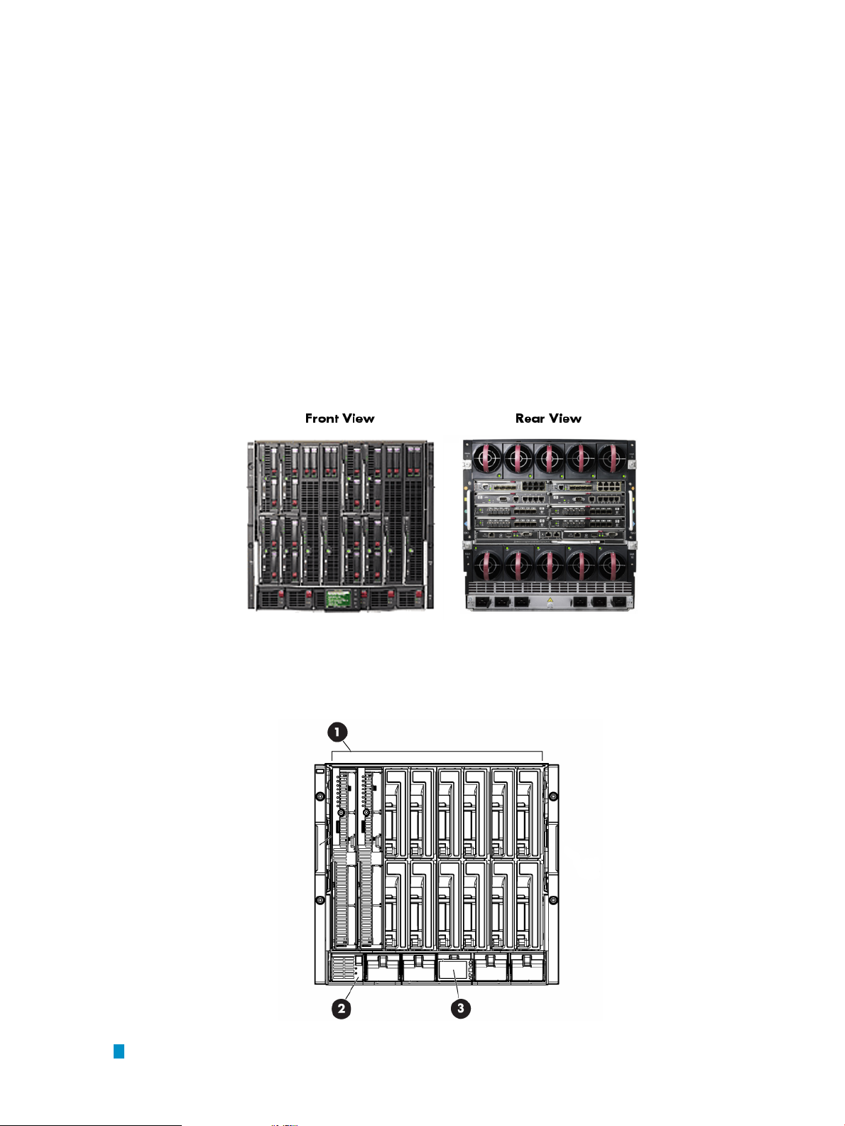
Figure 1-1 shows front and rear views of the HP BladeSystem c7000 enclosure.
Figure 1-1 HP BladeSystem c7000 enclosure (Front and Rear Views)
Figure 1-2 is an illustration showing the location of the device bays, power supply bays, and the
Insight Display at the front of the HP BladeSystem c7000 enclosure.
Figure 1-2 HP BladeSystem c7000 Enclosure Bay Locations (Front View)
1
Device bays
22 Hardware and Network Overview
Page 23
2
Power supply bays
3
Insight Display. For more information, see “Insight Display” (page 28).
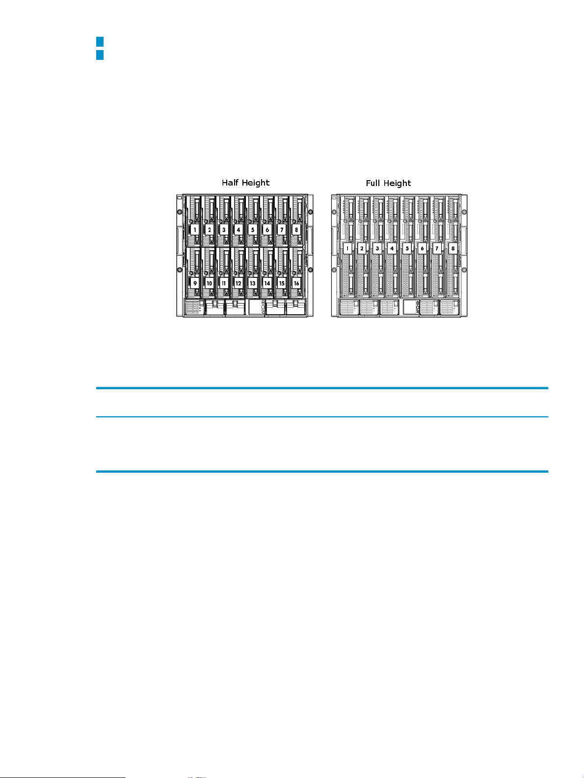
As shown in Figure 1-3, the HP BladeSystem c7000 enclosure can house a maximum of 16
half-height or 8 full-height server blades. The c7000 enclosure can contain a maximum of 6 power
supplies and 10 fans. Figure 1-3 also illustrates the numbering scheme for the server bays in
which server blades are inserted. The numbering scheme differs for half height and full height
server blades.
Figure 1-3 HP BladeSystem c7000 Enclosure Bay Numbering for Half Height and Full Height Server
Blades
The number of fans in the enclosure influences the placement of the server blades. Use the
following table and the numbering scheme in Figure 1-3 to determine the placement of the server
blades in the enclosure, based on the number of fans.
Insert Half-Height Server Blades in
These BaysNumber of Fans
4 fans
1 Only two servers are supported in this configuration. They can be inserted in any two of these bays.
1
Insert Full-Height Server Blades in These
Bays
1 or 21, 2, 9, 10
1, 2, 3, 41, 2, 3, 4, 9, 10, 11, 126 fans
all server baysall server bays8 or 10 fans
Figure 1-4 is an illustration showing the location of the fan bays, interconnect bays, onboard
administrator bays, the power supply exhaust vent, and the AC power connections at the rear
of the HP BladeSystem c7000 enclosure. This figure includes an inset showing the serial connector,
onboard administrator/iLO port, and the enclosure Uplink and Downlink ports.
1.2 Server Blade Enclosure Components 23
Page 24
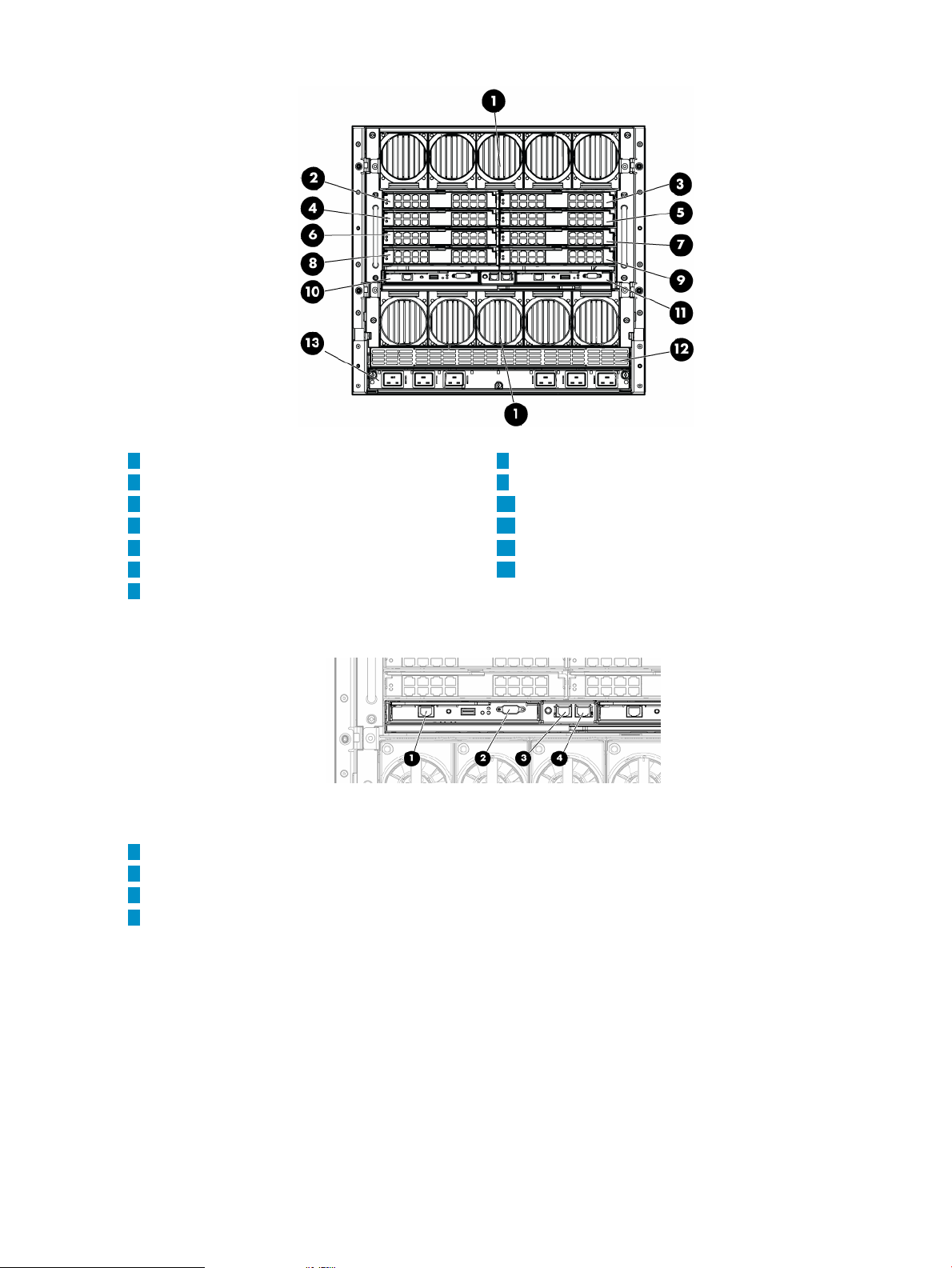
Figure 1-4 HP BladeSystem c7000 Enclosure Bay Locations (Rear View)
1
Fan Bays
2
Interconnect Bay #1
3
Interconnect Bay #2
4
Interconnect Bay #3
5
Interconnect Bay #4
6
Interconnect Bay #5
7
Interconnect Bay #6
1
Onboard Administrator/Integrated Lights Out port
2
Serial connector
3
Enclosure Downlink port
4
Enclosure Uplink port
8
Interconnect Bay #7
9
Interconnect Bay #8
10
Onboard Administrator Bay 1
11
Onboard Administrator Bay 2
12
Power Supply Exhaust Vent
13
AC Power Connections
General Configuration Guidelines
The following are general guidelines for configuring HP BladeSystem c7000 enclosures:
• Up to four enclosures can be mounted in an HP 42U Infrastructure Rack.
• If an enclosure is not fully populated with fans and power supplies, see the positioning
guidelines in the HP BladeSystem c7000 enclosure documentation.
• Enclosures are cabled together using their uplink and downlink ports.
• The top uplink port in each rack is used as a service port to attach a laptop or other device
for initial configuration or subsequent debugging.
24 Hardware and Network Overview
Page 25
Specific HP XC Setup Guidelines
The following enclosure setup guidelines are specific to HP XC:
• On every HP BladeSystem c7000 enclosure, an Ethernet interconnect module (either a switch
or pass-through module) is installed in interconnect bay #1 (see callout 2 in Figure 1-4) for
the administration network.
• Hardware configurations that use Gigabit Ethernet as the interconnect require an additional
Ethernet interconnect module (either a switch or pass-through module) to be installed in
interconnect bay #2 (see callout 3 in Figure 1-4) for the interconnect network.
• Systems thatuse InfiniBand as the interconnect require a double-wide InfiniBand interconnect
switch module installed in interconnect bays #5 and #6 (see callouts 6 and 7 in Figure 1-4).
• Some systems might need an additional Ethernet interconnect module to support server
blades that require external connections. For more information about external connections,
see “Cabling for the External Network” (page 41).
1.2.2 HP BladeSystem c3000 Enclosure
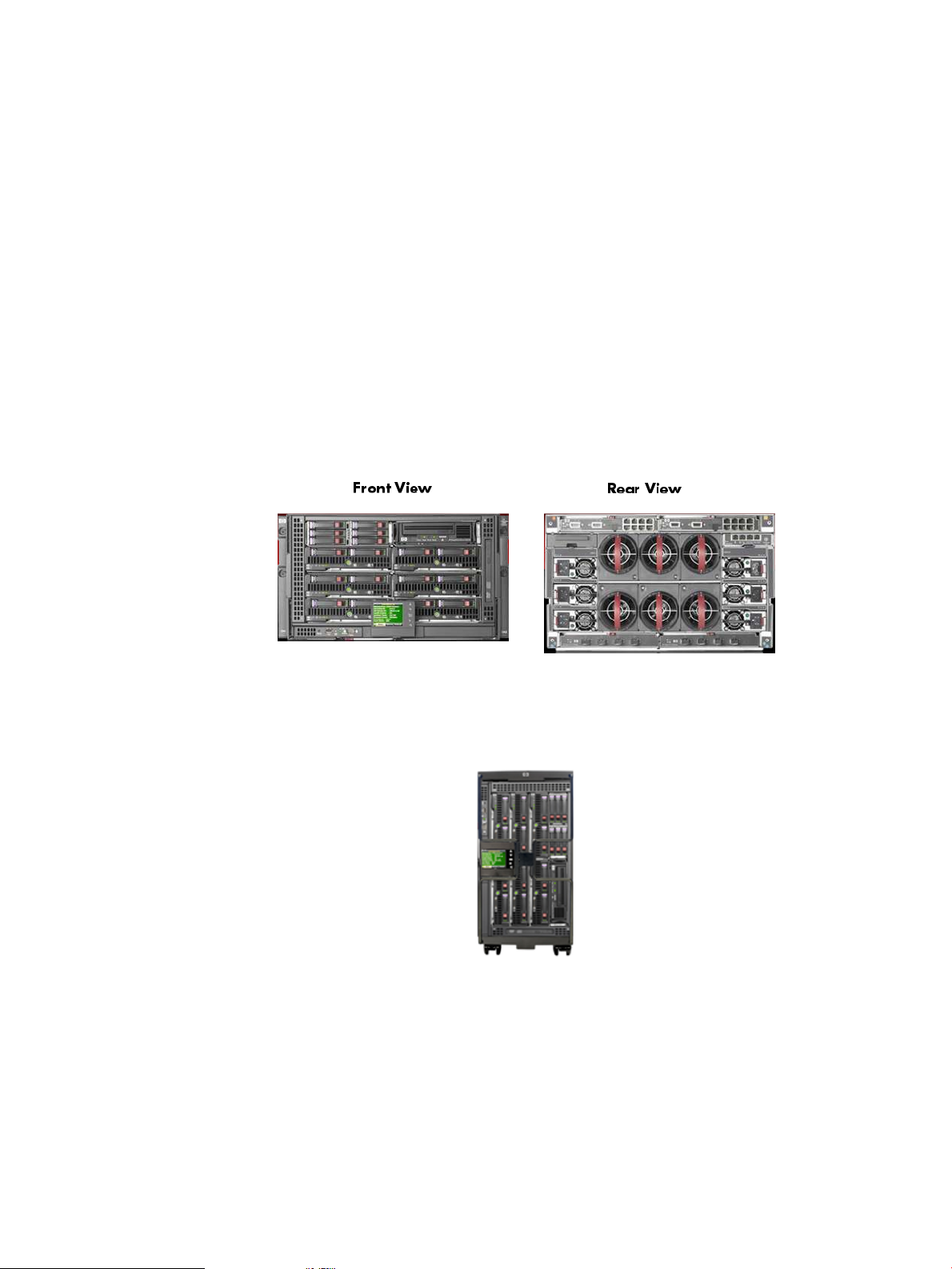
Figure 1-5 shows the front and rear views of the HP BladeSystem c3000 enclosure.
Figure 1-5 HP BladeSystem c3000 Enclosure (Front and Rear Views)
The HP BladeSystem c3000 Enclosure is available as a tower model, as shown in Figure 1-6.
Figure 1-6 HP BladeSystem c3000 Enclosure Tower Model
Figure 1-7 is an illustration showing the location of the device bays, optional DVD drive, Insight
display, and Onboard Administrator at the front of the HP BladeSystem c3000 Enclosure.
1.2 Server Blade Enclosure Components 25
Page 26
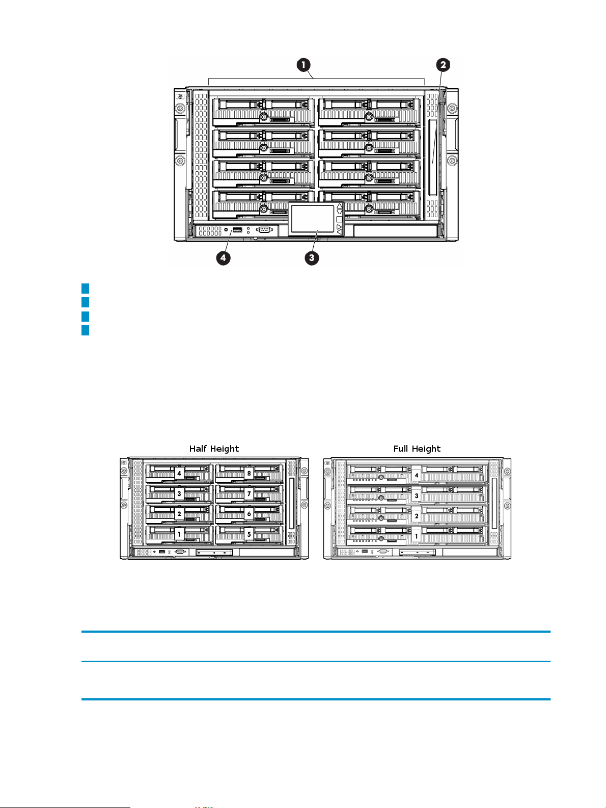
Figure 1-7 HP BladeSystem c3000 Enclosure Bay Locations (Front View)
1
Device bays
2
DVD drive (optional)
3
Insight Display. For more information, see “Insight Display” (page 28).
4
Onboard Administrator (OA)
The HP BladeSystem c3000 enclosure can house a maximum of 8 half-height or 4 full-height
server blades. Additionally, the c3000 enclosure contains an integrated DVD drive, which is
useful for installing the HP XC System Software. Figure 1-8 illustrates the numbering of the
server bays of the HP BladeSystem c3000 enclosure for both half height and full height server
blades.
Figure 1-8 HP BladeSystem c3000 Enclosure Bay Numbering
The number of fans in the enclosure influences the placement of the server blades. Use the
following table and the numbering scheme in Figure 1-8 to determine the placement of the server
blades in the enclosure, based on the number of fans.
Insert Half-Height Server Blades in
These BaysNumber of Fans
Insert Full-Height Server Blades in These
Bays
Figure 1-9 is an illustration showing the location of the interconnect bays, fan bays, onboard
administrator bays, the enclosure/onboard administrator link module, and power supplies at
the rear of the HP BladeSystem c3000 enclosure. This figure includes an inset showingthe onboard
administrator/iLO port, and the enclosure Uplink and downlink ports.
26 Hardware and Network Overview
1, 21, 2, 5, 64 fan configuration
anyany6 fan configuration
Page 27
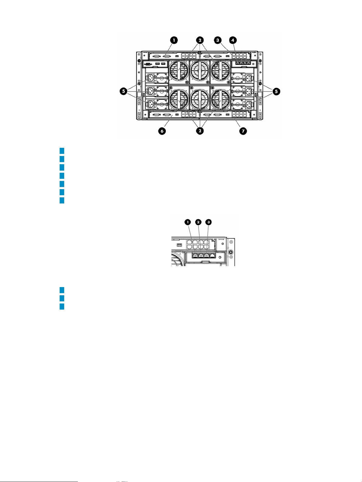
Figure 1-9 HP BladeSystem c3000 Enclosure Bay Locations (Rear View)
1
Interconnect bay #1
2
Fans
3
Interconnect bay #2
4
Enclosure/Onboard Administrator Link Module
5
Power Supplies
6
Interconnect bay #3
7
Interconnect bay #4
1
Enclosure Downlink port
2
Enclosure Uplink port
3
Onboard Administrator/Integrated Lights Out port
Specific HP XC Setup Guidelines
The following enclosure setup guidelines are specific to HP XC:
• On every enclosure, an Ethernet interconnect module (either a switch or pass-through
module) is installed in interconnect bay #1 (see callout 1 in Figure 1-9) for the administration
network.
• Hardware configurations that use Gigabit Ethernet as the interconnect can share with the
administration network in interconnect bay #1.
• Systems thatuse InfiniBand as the interconnect require a double-wide InfiniBand interconnect
switch module installed in interconnect bays #3 and #4 (see callouts 6 and 7 in Figure 1-9).
• Some systems might need an additional Ethernet interconnect module to support server
blades that require external connections. For more information about external connections,
see “Cabling for the External Network” (page 41).
1.2.3 HP BladeSystem c-Class Onboard Administrator
The Onboard Administrator is the management device for an enclosure, and at least one Onboard
Administrator is installed in every enclosure.
1.2 Server Blade Enclosure Components 27
Page 28
You can access the Onboard Administrator through a graphical Web-based user interface, a
command-line interface, or the simple object access protocol (SOAP) to configure and monitor
the enclosure.
You can add a second Onboard Administrator to provide redundancy.
The Onboard Administrator requires a password. For information on setting the Onboard
Administrator Password, see “Setting the Onboard Administrator Password” (page 62).
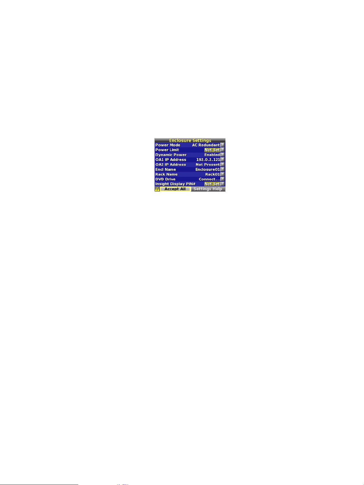
1.2.4 Insight Display
The Insight Display is a small LCD panel on the front of an enclosure that provides instant access
to important information about the enclosure such as the IP address and color-coded status.
Figure 1-10 depicts the Insight Display.
Figure 1-10 Server Blade Insight Display
You can use the Insight Display panel to make some basic enclosure settings.
1.3 Server Blade Mezzanine Cards
The mezzanine slots on each server blade provide additional I/O capability.
Mezzanine cards are PCI-Express cards that attach inside the server blade through a special
connector and have no physical I/O ports on them.
Card types include Ethernet, fibre channel, or 10 Gigabit Ethernet.
1.4 Server Blade Interconnect Modules
An interconnect module provides the physical I/O for the built-in NICs or the supplemental
mezzanine cards on the server blades. An interconnect module can be eithera switch or a pass-thru
module.
A switch provides local switching and minimizes cabling. Switch models that are supported as
interconnect modules include, but are not limited to:
• Nortel GbE2c Gigabit Ethernet switch
• Cisco Catalyst Gigabit Ethernet switch
• HP 4x DDR InfiniBand switch
• Brocade SAN switch
A pass-thru module provides direct connections to the individual ports on each node and does
not provide any local switching.
Bays in the back of each enclosure correspond to specific interfaces on the server blades. Thus,
all I/O devices that correspond to a specific interconnect bay must be the same type.
Interconnect Bay Port Mapping
Connections between the server blades and the interconnect bays are hard wired. Each of the 8
interconnect bays in the back of the enclosure has a connection to each of the 16 server bays in
the front of the enclosure. The built-in NIC or mezzanine card into which the interconnect blade
connects dependson which interconnect bay it is pluggedinto. Because full-height blades consume
two server bays, they have twice as many connections to each of the interconnect bays.
28 Hardware and Network Overview
Page 29

See the HP BladeSystem Onboard Administrator User Guide for illustrations of interconnect bay
port mapping connections on half- and full-height server blades.
1.5 Supported Console Management Devices
Table 1-3 lists the supported console management device for each hardware model within each
cluster platform. The console management device provides remote access to the console of each
node, enablingfunctions such as remote power management, remote console logging, and remote
boot.
HP workstation models do not have console ports.
HP ProLiant servers provide remote management features through a baseboard management
controller (BMC). The BMC enables functions such as remote power management and remote
boot. HP ProLiant BMCs comply with a specified release of the industry-standard Intelligent
Platform Management Interface (IPMI). HP XC supports two IPMI-compliant BMCs: integrated
lights out (iLO and iLO2) and Lights-Out 100i (LO-100i), depending on the server model.
Each HP ProLiant server blade has a built-in Integrated Lights Out (iLO2) device that provides
full remote power control and serial console access. You can access the iLO2 device through the
Onboard Administrator. On server blades, iLO2 advanced features are enabled by default and
include the following:
• Full remote graphics console access including full keyboard, video, mouse (KVM) access
through a Web browser
• Support for remote virtual media which enables you to mount a local CD or diskette and
serve it to the server blade over the network
Each HP Integrity server blade has a built-in management processor (MP) device that provides
full remote power control and serial console access. You can access the MP device by connecting
a serial terminal or laptop serial port to the local IO cable that is connected to the server blade.
Hardware models that use iLO and iLO2 need certain settings that cannot be made until the iLO
has an IP address. The HP XC System Software Installation Guide provides instructions for using
a browser to connect to the iLO and iLO2 to enable telnet access.
Table 1-3 Supported Console Management Devices
Firmware DependencyHardware Component
CP3000
Lights-out 100i management (LO-100i), system BIOSHP ProLiant DL140 G2
LO-100i, system BIOSHP ProLiant DL140 G3
LO-100i, system BIOSHP ProLiant DL160 G5
Integrated lights out (iLO), system BIOSHP ProLiant DL360 G4
iLO, system BIOSHP ProLiant DL360 G4p
iLO2, system BIOSHP ProLiant DL360 G5
iLO, system BIOSHP ProLiant DL380 G4
iLO2, system BIOSHP ProLiant DL380 G5
iLO2, system BIOSHP ProLiant DL580 G4
iLO2, system BIOSHP ProLiant DL580 G5
CP3000BL
iLO2, system BIOS, Onboard Administrator (OA)HP ProLiant BL2x220c G5
iLO2, system BIOS, Onboard Administrator (OA)HP ProLiant BL260c G5
1.5 Supported Console Management Devices 29
Page 30

Table 1-3 Supported Console Management Devices (continued)
Firmware DependencyHardware Component
iLO2, system BIOS, Onboard Administrator (OA)HP ProLiant BL460c
iLO2, system BIOS, OAHP ProLiant BL480c
iLO2, system BIOS, Onboard Administrator (OA)HP ProLiant BL680c G5
CP4000
LO-100iHP ProLiant DL145
LO-100iHP ProLiant DL145 G2
LO-100iHP ProLiant DL145 G3
LO-100iHP ProLiant DL165 G5
iLO2HP ProLiant DL365
iLO2HP ProLiant DL365 G5
iLO2HP ProLiant DL385
iLO2HP ProLiant DL385 G2
iLO2HP ProLiant DL385 G5
iLO2HP ProLiant DL585
CP4000BL
CP6000
CP6000BL
iLO2HP ProLiant DL585 G2
iLO2HP ProLiant DL585 G5
iLO2HP ProLiant DL785 G5
iLO2HP ProLiant BL465c
iLO2HP ProLiant BL465c G5
iLO2HP ProLiant BL685c
iLO2HP ProLiant BL685c G5
Management Processor (MP)HP Integrity rx1620
MPHP Integrity rx2600
MPHP Integrity rx2620
MPHP Integrity rx2660
MPHP Integrity rx4640
MPHP Integrity rx8620
MPHP Integrity BL860c Server Blade (Full-height)
1.6 Administration Network Overview
The administration network is a private network within the HP XC system that is used primarily
for administrative operations. This network is treated as a flat network during run time (that is,
communication between any two points in the network is equal in communication time between
any other two points in the network). However, during the installation and configuration of the
30 Hardware and Network Overview
Page 31

HP XC system, the administrative tools probe and discover the topology of the administration
Compute Nodes
Root Console
Switch
Head
Node
Specialized Role Nodes
Root Administration Switch
Branch Console Switches
network. The administration network requires and uses Gigabit Ethernet.
The administration network has at least one Root Administration Switch and can have multiple
Branch Administration Switches. These switches are discussed in “Switches” (page 46).
1.7 Administration Network: Console Branch
The console branch is part of the private administration network within an HP XC system that
is used primarily for managing and monitoring the consoles of the nodes that comprise the HP
XC system. This branch of the network uses 10/100 Mbps Ethernet.
During the installation and configuration of the HP XC system, the administrative tools probe
and discover the topology of the entire administration network including the console branch.
A (nonblade) HP XC system has at least one Root Console Switch with the potential for multiple
Branch Console Switches. Figure 1-11 shows a graphical representation of the console branch.
Figure 1-11 Administration Network: Console Branch (Without HP Server Blades)
1.8 Interconnect Network
The interconnect network is a private network within the HP XC system. Typically, every node
in the HP XC system is connected to the interconnect.
The interconnect network is dedicated to communication between processors and access to data
in storage areas. It provides a high-speed communications path used primarily for user file
service and for communications within applications that are distributed among nodes of the
cluster.
Table 1-4 lists the supported interconnect types on each cluster platform. The interconnect types
are displayed in the context of an interconnect family, in which InfiniBand products constitute
one family, Quadrics® QsNetII® constitutes another interconnect family, and so on. For more
information about the interconnect types on individual hardware models, see the cluster platform
documentation.
1.7 Administration Network: Console Branch 31
Page 32

Table 1-4 Supported Interconnects
INTERCONNECT FAMILIES
InfiniBand PCI
Cluster
Platform and
Hardware
Model
1 Mellanox ConnectX Infiniband Cards require OFED Version 1.2.5 or later.
2 The HP ProLiant DL385 G2 and DL145 G3 servers require a PCI Express card in order to use this interconnect.
3 This interconnect is supported by CP6000 hardware models with PCI Express.
Gigabit
Ethernet
InfiniBand®
PCI-X
XXCP6000
Express Single
Data Rate and
Double Data
Rate (DDR)
3
X
InfiniBand
ConnectX
Double Data
Rate (DDR)
XXXCP3000BL
XXXCP4000BL
3
Myrinet® (Rev.
1
D, E, and F)
QsNet
XXXXXCP3000
2
XXXXXCP4000
X
XX
Mixing Adapters
Within a given interconnect family, several different adapters can be supported. However,
HP requires that all adapters must be from the same interconnect family; a mix of adapters
from different interconnect families is not supported.
InfiniBand Double Data Rate
All components in a network must be DDR to achieve DDR performance levels.
ConnectX InfiniBand Double Data Rate
Currently ConnectX adapters cannot be mixed with other types of adapters.
Myrinet Adapters
The Myrinet adapters can be either the single-port M3F-PCIXD-2 (Rev. D) or the dual port
M3F2–PCIXE-2 (Rev. E and Rev F); mixing adapter types is not supported.
QsNet
II
The QsNetIIhigh-speed interconnect from Quadrics, Ltd. is the only version of Quadrics
interconnect that is supported.
II
1.9 Large-Scale Systems
A typical HP XC system contains from 5 to 512 nodes. To allow systems of a greater size, an HP
XC system can be arranged into a large-scale configuration with up to 1024 compute nodes (HP
might consider larger systems as special cases).
This configuration arranges the HP XC system as a collection of hardware regions that are tied
together through a ProCurve 2848 Ethernet switch.
The nodes of the large-scale system are divided as equally as possible between the individual
HP XC systems, which are known as regions. The head node for a large-scale HP XC system is
always the head node of region 1.
32 Hardware and Network Overview
Page 33

2 Cabling Server Blades
The following topics are addressed in this chapter:
• “Blade Enclosure Overview” (page 33)
• “Network Overview ” (page 33)
• “Cabling for the Administration Network” (page 37)
• “Cabling for the Console Network” (page 38)
• “Cabling for the Interconnect Network” (page 39)
• “Cabling for the External Network” (page 41)
2.1 Blade Enclosure Overview
An HP XC blade cluster is made up of one or more "Blade Enclosures" connected together as a
cluster. Each blade enclosure must contain the following:
• 1 to 16 blade servers
• 1 Ethernet Interconnect blade in bay 1 for the Administration Network
• 1 Onboard Administrator (OA) for managing the enclosure
NOTE: Enclosures might also have a redundant Onboard Administrator.
• The requisite number of fans and power supplies to fill the needs of all the hardware
In addition, each enclosure needs an additional blade interconnect module for the cluster
interconnect. On a Gigabit Ethernet (GigE) cluster, this could be either another Ethernet Switch
or an Ethernet pass-thru module in bay 2. On an InfiniBand (IB) cluster, this would be one of the
double-wide IB Blade switches in bays 5 and 6.
In certain circumstances, there might need to be an additional Ethernet interconect blade needed
to support any required external connections. This would only be needed on Gigabit Ethernet
clusters with half-height blades that need external connections. For more information, see
“Configuring the External Network: Option 2” (page 42).
The various enclosures that make up a cluster are connected to each other through external
ProCurve switches. Every cluster needs at least one ProCurve Administrative Network switch
(a 2800 series) and may optionally have a Console Network Switch (a 2600 series). It is possible
to have the Console and Administrative Network combined over the single 2800 series switch
on smaller configurations.
Gigabit Ethernet clusters require one or more external Ethernet switches to act as the cluster
interconnect between the enclosures. This can be set up one of two ways.
• If the cluster uses Ethernet switches in each enclosure, then you need a smaller external
interconnect because you only need one connection for each enclosure in the cluster (although
this might be a trunked connection).
• If the cluster uses Ethernet pass-through modules in each enclosure, you need a large external
Ethernet switch with enough connections for each node in the cluster.
InfiniBand clusters require one or more external IB switches, with at least one managed switch
to manage the fabric.
2.2 Network Overview
An HP XC system consists of several networks: administration, console, interconnect, and external
(public). In order for these networks to function, you must connect the enclosures, server blades,
and switches according to the guidelines provided in this chapter.
2.1 Blade Enclosure Overview 33
Page 34

Chapter 3 (page 45) describes specific node and switch connections for non-blade hardware
configurations.
A hardware configuration with server blades does not have these specific cabling requirements;
specific switch port assignments are not required. However, HP recommends a logical ordering
of the cables on the switches to facilitate serviceability. Enclosures are discovered in port order,
so HP recommends that you cable them in the order you want them to be numbered. Also, HP
recommends that you cable the enclosures in lower ports and cable the external nodes in the
ports above them.
The configuration of an HP XC Blade Systemdepends on its size. Larger clusters require additional
switches to manage the additional enclosures or regions. Figure 2-1 (page 35), Figure 2-2 (page 36),
and Figure 2-3 (page 37) provide a general view of the cabling requirements for small, medium,
and large systems.
Additionally, Appendix B (page 143) provides several network cabling illustrations based on the
interconnect type and server blade height to use as a reference.
Small HP XC Cluster of Server Blades
Figure 2-1 (page 35) provides two illustrations of a small HP XC cluster of four enclosures and
a maximum of 64 nodes.
The top portion shows a Gigabit Ethernet switch with two connections for each of the four
enclosures: one connection to the (ProCurve managed) Gigabit Ethernet switch on the enclosure
and the other to the Onboard Administrator.
The bottom portion provides some additional detail. It shows the ProCurve managed Gigabit
Ethernet switch connected to the Gigabit Ethernet switch in bay 1 of each enclosure and to the
Primary Onboard Administrator External Link of each enclosure.
34 Cabling Server Blades
Page 35

Figure 2-1 Interconnection Diagram for a Small HP XC Cluster of Server Blades
Enclosure 4
May be any managed
GigE switch supported
by CP
ProCurve managed
GigE Switch
ProCurve managed
GigE Switch
Enclosure 1
Switch 1
Enclosure 1
Server Blades
NIC1
Enclosure 2
Server Blades
NIC1
Enclosure 3
Server Blades
NIC1
Enclosure 4
Server Blades
NIC1
Primary OA Ext LinkSecondary OA Ext Link
GigE Switch
Enclosure 3
Primary OA Ext LinkSecondary OA Ext Link
GigE Switch
Enclosure 2
Primary OA Ext LinkSecondary OA Ext Link
GigE Switch
Enclosure 1
Primary OA Ext LinkSecondary OA Ext Link
GigE Switch
Enclosure 2
Switch 1
Enclosure 3
Switch 1
Enclosure 4
Switch 1
Enclosure 1OAEnclosure 2OAEnclosure 3OAEnclosure 4
OA
Medium Sized HP XC Cluster of Server Blades
Figure 2-2 (page 36) provides two illustrations of a medium sized HP XC cluster of 32 enclosures
and a maximum of 512 nodes.
The top portion shows a Gigabit Ethernet switch (a ProCurve 2848) that is connected to the
enclosure switch in bay 1 of each enclosure as well as to a ProCurve 2650 switch that connects
to the Onboard Administrator external link of each enclosure.
The bottom portion provides some additional detail. It shows the ProCurve managed Gigabit
Ethernet switch connected to the Gigabit Ethernet switch of each enclosure and to a ProCurve
2650 switch, which connects the Primary Onboard Administrator External Link of each enclosure.
2.2 Network Overview 35
Page 36

Figure 2-2 Interconnection Diagram for a Medium Sized HP XC Cluster of Server Blades
Enclosure 4
Smaller systems
may use
ProCurve 2626
ProCurve 2650
ProCurve 2848
Enclosure 1
Switch 1
Enclosure 1
Server Blades
NIC1
Enclosure 2
Server Blades
NIC1
Enclosure 3
Server Blades
NIC1
Primary OA Ext LinkSecondary OA Ext Link
GigE Switch
Enclosure 3
Primary OA Ext LinkSecondary OA Ext Link
GigE Switch
Enclosure 2
Primary OA Ext LinkSecondary OA Ext Link
GigE Switch
Enclosure 1
Primary OA Ext LinkSecondary OA Ext Link
GigE Switch
Enclosure 2
Switch 1
Enclosure 32
Switch 1
Enclosure 1
OA
Ext Link
Enclosure 2
OA
Ext Link
Enclosure 32
OA
Ext Link
Enclosure 32
OA
Ext Link
Enclosure 32
GigE switch
May be any
ProCurve managed
GigE switch
(smaller systems may use
ProCurve 2824)
. . .
. . .
ProCurve 2650
GigE Switch
Large HP XC Cluster of Server Blades
Figure 2-3 (page 37) illustrates a large HP XC cluster of eight regions, with 32 enclosures per
region.
There is a Gigabit Ethernet switch for the HP XC system that is connected to a Gigabit Ethernet
switch in each region.
The Gigabit Ethernet switch in a region is connected to each enclosure's Gigabit Ethernet switch
in bay 1 and to a ProCurve 2650 switch. The ProCurve 2650 switch is connected to the Primary
Onboard Administrator External Link of each enclosure.
36 Cabling Server Blades
Page 37

Figure 2-3 Interconnection Diagram for a Large HP XC Cluster of Server Blades
Enclosure 1
GigE Switch
GigE Switch
Region 1 Region 8
/4 /4
ProCurve 2650
Primary OA Ext LinkSecondary OA Ext Link
GigE Switch
Enclosure 2
Primary OA Ext LinkSecondary OA Ext Link
GigE Switch
Enclosure 3
Primary OA Ext LinkSecondary OA Ext Link
GigE Switch
Enclosure 4
Primary OA Ext LinkSecondary OA Ext Link
GigE Switch
Enclosure 32
OA
Ext Link
Enclosure 32
GigE
Switch 1
. . .
. . .
Enclosure 481
GigE Switch
ProCurve 2650
Primary OA Ext LinkSecondary OA Ext Link
GigE Switch
Enclosure 482
Primary OA Ext LinkSecondary OA Ext Link
GigE Switch
Enclosure 483
Primary OA Ext LinkSecondary OA Ext Link
GigE Switch
Enclosure 484
Primary OA Ext LinkSecondary OA Ext Link
GigE Switch
Enclosure 512
OA
Ext Link
Enclosure 512
GigE
Switch 1
. . .
2.3 Cabling for the Administration Network
For server blades, the administration network is created and connected throughProCurve model
2800 series switches. One switch is designated as the root administration switch and that switch
can be connected to multiple branch administration switches, if required.
NIC1 on each server blade is dedicated as the connection to the administration network. NIC1
of all server blades connects to interconnect bay 1 on the enclosure.
The entire administration network is formed by connecting the device (either a switch or a
pass-thru module) in interconnect bay 1 of each enclosure to one of the ProCurve administration
network switches.
Non-blade server nodes must also be connected to the administration network. See Chapter 3
(page 45) to determine which port on the node is used for the administration network; the port
you use depends on your particular hardware model.
Figure 2-4 illustrates the connections that form the administration network.
2.3 Cabling for the Administration Network 37
Page 38

Figure 2-4 Administration Network Connections
NIC 1
NIC 2
NIC 3
NIC 4
MEZZ 1
MEZZ 2
MEZZ 3
iLO2
NIC 1
NIC 2
MEZZ 1
MEZZ 2
iLO2
Interconnect bay 1
Interconnect bay 2
Interconnect bay 3
Interconnect bay 4
Interconnect bay 5
Interconnect bay 6
Interconnect bay 7
Interconnect bay 8
ONBOARD
ADMINISTRATOR
MGT
NIC
PCI
SLOT
PCI SLOT
NIC
Non-Blade Server
C-Class Blade Enclosure
Admin ProCurve 2800 Series Switch
Console ProCurve 2600 Series Switch
Gigabit Ethernet Interconnect Switch
MGT
NIC
PCI
SLOT
PCI SLOT
NIC
Non-Blade Server
External Public Network
E
D
A
L
B
T
H
G
I
EH
L
L
U
F
E
D
A
LB
T
H
G
IE
H
F
L
A
H
2.4 Cabling for the Console Network
The console network is part of the private administration network within an HP XC system, and
it is used primarily for managing and monitoring the node consoles.
On a small cluster, the console management devices can share a single top-level ProCurve 2800
root administration switch. On larger hardware configurations that require more ports, the
console network is formed with separate ProCurve model 2600 series switches.
You arrange these switches in a hierarchy similar to the administration network. One switch is
designated as the root console switch and that switch can be connected to multiple branch console
switches. The top-level root console switch is then connected to the root administration switch.
HP server blades use iLO2 as the console management device. Each iLO2 in an enclosure connects
to the Onboard Administrator. To form the console network, connect the Onboard Administrator
of each enclosure to one of the ProCurve console switches.
Non-blade server nodes must also be connected to the console network. See Chapter 3 (page 45)
to determine which port on the node is used for the console network; the port you use depends
on your particular hardware model.
Figure 2-5 illustrates the connections that form the console network.
38 Cabling Server Blades
Page 39

Figure 2-5 Console Network Connections
NIC 1
NIC 2
NIC 3
NIC 4
MEZZ 1
MEZZ 2
MEZZ 3
iLO2
NIC 1
NIC 2
MEZZ 1
MEZZ 2
iLO2
Interconnect bay 1
Interconnect bay 2
Interconnect bay 3
Interconnect bay 4
Interconnect bay 5
Interconnect bay 6
Interconnect bay 7
Interconnect bay 8
ONBOARD
ADMINISTRATOR
MGT
NIC
PCI
SLOT
PCI SLOT
NIC
Non-Blade Server
C-Class Blade Enclosure
Admin ProCurve 2800 Series Switch
Console ProCurve 2600 Series Switch
Gigabit Ethernet Interconnect Switch
MGT
NIC
PCI
SLOT
PCI SLOT
NIC
Non-Blade Server
External Public Network
2.5 Cabling for the Interconnect Network
The interconnect network is a private network within an HP XC system. Typically, every node
in an HP XC system is connected to the interconnect. The interconnect network provides a
high-speed communications path used primarily for user file service and for communications
within applications that are distributed among nodes in the cluster.
Gigabit Ethernet and InfiniBand are supported as the interconnect types for HP XC hardware
configurations with server blades and enclosures. The procedure to configure the interconnect
network depends upon the type of interconnect in use.
• “Configuring a Gigabit Ethernet Interconnect” (page 39)
• “Configuring an InfiniBand Interconnect” (page 40)
• “Configuring the Interconnect Network Over the Administration Network” (page 41)
2.5.1 Configuring a Gigabit Ethernet Interconnect
A Gigabit Ethernet interconnect requires one or more external Ethernet switches to act as the
interconnect between the enclosures that make up the HP XC system.
On systems using a Gigabit Ethernet interconnect, one NIC on each server blade is dedicated as
the connection to the interconnect network. On a server blade, NIC2 is used for this purpose.
NIC2 of all server blades connects to interconnect bay 2 on the enclosure.
The entire interconnect network is formed by connecting the device (either a switch or a pass-thru
module) in interconnect bay 2 of each enclosure to one of the Gigabit Ethernet interconnect
switches.
If the device is a switch, the Gigabit uplink to the higher level ProCurve switch can be a single
wire or a trunked connection of 2, 4, or 8 wires. If the device is a pass-thru module, there must
be one uplink connection for each server blade in the enclosure.
Non-blade server nodes must also be connected to the interconnect network. See Chapter 3
(page 45) to determine which port on the node is used for the interconnect network; the port
you use depends on your particular hardware model.
Figure 2-6 illustrates the connections for a Gigabit Ethernet interconnect.
2.5 Cabling for the Interconnect Network 39
Page 40

Figure 2-6 Gigabit Ethernet Interconnect Connections
NIC 1
NIC 2
NIC 3
NIC 4
MEZZ 1
MEZZ 2
MEZZ 3
iLO2
NIC 1
NIC 2
MEZZ 1
MEZZ 2
iLO2
Interconnect bay 1
Interconnect bay 2
Interconnect bay 3
Interconnect bay 4
Interconnect bay 5
Interconnect bay 6
Interconnect bay 7
Interconnect bay 8
ONBOARD
ADMINISTRATOR
MGT
NIC
PCI
SLOT
PCI SLOT
NIC
Non-Blade Server
C-Class Blade Enclosure
Admin ProCurve 2800 Series Switch
Console ProCurve 2600 Series Switch
Gigabit Ethernet Interconnect Switch
MGT
NIC
PCI SLOT
PCI SLOT
NIC
Non-Blade Server
External Public Network
NIC 1
NIC 2
NIC 3
NIC 4
MEZZ 1
MEZZ 2
MEZZ 3
iLO2
NIC 1
NIC 2
MEZZ 1
MEZZ 2
iLO2
Interconnect bay 1
Interconnect bay 2
Interconnect bay 3
Interconnect bay 4
Interconnect bays
Interconnect bay 7
Interconnect bay 8
ONBOARD
ADMINISTRATOR
MGT
NIC
PCI
SLOT
PCI SLOT
NIC
Non-Blade Server
C-Class Blade Enclosure
Admin ProCurve 2800 Series Switch
Console ProCurve 2600 Series Switch
Infiniband Interconnect Switch
MGT
NIC
PCI SLOT
PCI SLOT
NIC
Non-Blade Server
External Public Network
5 & 6 (double wide)
Infini
Band
Mezzani
ne
Cards
Double wide
InfiniBand switch
modu
le
InfiniBand PCI Cards
2.5.2 Configuring an InfiniBand Interconnect
An InfiniBand interconnect requires one or more external InfiniBand switches with at least one
managed switch to manage the fabric.
Systems using an InfiniBand interconnect require you to install an InfiniBand mezzanine card
into mezzanine bay 2 of each server blade to provide a connection to the InfiniBand interconnect
network. The InfiniBand card in mezzanine bay 2 connects to the double-wide InfiniBand switch
in interconnect bays 5 and 6 on the enclosure.
The entire interconnect network is formed by connecting the InfiniBand switches in interconnect
bays 5 and 6 of each enclosure to one of the InfiniBand interconnect switches.
Non-blade server nodes also require InfiniBand cards and must also be connected to the
interconnect network.
Figure 2-7 illustrates the connections for an InfiniBand interconnect.
Figure 2-7 InfiniBand Interconnect Connections
40 Cabling Server Blades
Page 41

2.5.3 Configuring the Interconnect Network Over the Administration Network
In cases where an additional Gigabit Ethernet port or switch may not be available, the HP XC
System Software enables you toconfigure the interconnect on the administration network. When
the interconnect is configured on the administration network, only a single LAN is used.
To configure the interconnect on the administration network, include the --ic=AdminNet
option on the discover command line, which is documented in the HP XC System Software
Installation Guide.
Be aware that configuring the interconnect on the administration network may negatively impact
system performance.
2.6 Cabling for the External Network
Depending upon the roles you assign to nodes during the cluster configuration process, some
nodes mightrequire connections to an external public network. Making these connections requires
one or more Ethernet ports in addition to the ports already in use. The ports you use depend
upon the hardware configuration and the number of available ports.
On non-blade server nodes, the appropriate port assignments for the external network are shown
in Chapter 4 (page 59).
On a server blade, the number of available Ethernet ports is influenced by the type of interconnect
and the server blade height:
• Nodes in clusters that use an InfiniBand interconnect have only one NIC in use for the
administration network.
• Nodes in clusters that use a Gigabit Ethernet interconnect have two NICs in use; one for the
administration network, and one for the interconnect network.
• Half-height server blade models have two built-in NICs.
• Full-height server blade models have four built-in NICs.
You can use the built-in NICs on a server blade if any are available. If the node requires more
ports, you must add an Ethernet card to mezzanine bay 1 on the server blade. If you add an
Ethernet card to mezzanine bay 1, you must also add an Ethernet interconnect module (either a
switch or pass-thru module) to interconnect bay 3 or 4 of the c7000 enclosure.
On full-height server blades, you can avoid having to purchase an additional mezzanine card
and interconnect module by creating virtual local area networks (VLANs). On a full-height server
blade, NICs 1 and 3 are both connected to interconnect bay 1, and, for the c7000 enclosure, NICs
2 and 4 are both connected to interconnect bay 2. If you are using one of these NICs for the
connection to the external network, you might have to create a VLAN on the switch in that bay
to separate the external network from other network traffic.
For information about configuring VLANs, see “Creating VLANs” (page 44).
The ports and interconnect bays used for external network connections vary depending on the
hardware configuration, the ports that are already being used for the other networks, and the
server blade height. For more information about how to configure the external network in these
various configurations, see the illustrations in the following sections:
• “Configuring the External Network: Option 1” (page 41)
• “Configuring the External Network: Option 2” (page 42)
• “Configuring the External Network: Option 3 - Non Gigabit Ethernet Interconnect Clusters”
(page 43)
2.6.1 Configuring the External Network: Option 1
Figure 2-8 (page 42) assumes that NIC1 and NIC2 are already in use for the administration and
interconnect networks. This situation requires a third NIC for the external network. Half-height
2.6 Cabling for the External Network 41
Page 42

server blades do not have three NICs, and therefore, half-height server blades are not included
NIC 1
NIC 2
NIC 3
NIC 4
MEZZ 1
MEZZ 2
MEZZ 3
iLO2
NIC 1
NIC 2
MEZZ 1
MEZZ 2
iLO2
Interconnect bay 1
Interconnect bay 2
Interconnect bay 3
Interconnect bay 4
Interconnect bay 5
Interconnect bay 6
Interconnect bay 7
Interconnect bay 8
ONBOARD
ADMINISTRATOR
MGT
NIC
PCI
SLOT
PCI SLOT
NIC
Non-Blade Server
C-Class Blade Enclosure
Admin ProCurve 2800 Series Switch
Console ProCurve 2600 Series Switch
Gigabit Ethernet Interconnect Switch
MGT
NIC
PCI
SLOT
PCI SLOT
NIC
Non-Blade Server
ADMIN VLAN
EXTERNAL VLAN
External Public Network
E
D
A
L
B
T
H
G
I
E
H
L
L
U
F
E
D
A
L
B
T
H
G
I
E
H
F
LA
H
Ethernet PCI Cards
in this example
Because NIC1 and NIC3 on a full-height server blade are connected to interconnect bay 1, you
must use VLANs on the switch in that bay to separate the external network from the
administration network.
Also, in this example, PCI Ethernet cards are used in the non-blade server nodes. If the hardware
configuration contains non-blade server nodes, see Chapter 4 (page 59) for information on which
port to use for the external network.
Figure 2-8 External Network Connections: Full-Height Server Blades and NIC1 and NIC2 in Use
2.6.2 Configuring the External Network: Option 2
Figure 2-9 (page 43) assumes that NIC1 and NIC2 are already in use for the administration and
interconnect networks. This situation requires a third NIC for the external network, but unlike
Figure 2-8 (page 42), this hardware configuration includes half-height server blades. Therefore,
to make another Ethernet NIC available, you must add an Ethernet card to mezzanine bay 1 on
each server blade that requires an external connection. You must also install an Ethernet
interconnect module in interconnect bay 3 for these cards.
In addition, PCI Ethernet Cards are used in the non-blade server nodes. If the hardware
configuration contains non-blade server nodes, seeChapter 4 (page 59) for information on which
port to use for the external network.
42 Cabling Server Blades
Page 43

Figure 2-9 External Network Connections: Half-Height Server Blades and NIC1 and NIC2 in Use
NIC 1
NIC 2
NIC 3
NIC 4
MEZZ 1
MEZZ 2
MEZZ 3
iLO2
NIC 1
NIC 2
MEZZ 1
MEZZ 2
iLO2
Interconnect bay 1
Interconnect bay 2
Interconnect bay 3
Interconnect bay 4
Interconnect bay 5
Interconnect bay 6
Interconnect bay 7
Interconnect bay 8
ONBOARD
ADMINISTRATOR
MGT
NIC
PCI
SLOT
PCI SLOT
NIC
Non-Blade Server
C-Class Blade Enclosure
Admin ProCurve 2800 Series Switch
Console ProCurve 2600 Series Switch
Gigabit Ethernet Interconnect Switch
MGT
NIC
PCI
SLOT
PCI SLOT
NIC
Non-Blade Server
External Public Network
E
D
A
L
B
T
H
G
I
E
H
L
L
U
F
ED
A
L
B
T
H
G
I
EH
F
L
A
H
Ethernet PCI Cards
Ethernet
Mezzanine
Ca
rds
2.6.3 Configuring the External Network: Option 3 - Non Gigabit Ethernet Interconnect Clusters
The administration network requires only one network interface, NIC1, on clusters that do not
use Gigabit Ethernet as the interconnect (that is, they use InfiniBand or the interconnect on the
administration network).
On these non Gigabit Ethernet interconnect clusters, you have two configuration methods to
configure an external network connection, and the option you choose depends on whether the
collection of nodes requiring external connections includes half-height server blades.
• If only full height server blades require external connections, you can use NIC3 for the
external network. This is similar to the way the external connection is configured in Figure 2-8
(page 42), and it saves the cost of an additional interconnect device in bay 2.
• If half-height server blades require external connections, you cannot use NIC3 because half
height server blades do not have a third NIC. In this case, you must use NIC2 as the external
connection as shown in Figure 2-8 (page 42). This configuration requires an Ethernet
interconnect module to be present in bay 2.
Figure 2-8 (page 42) also shows the use of built-in NICs in the non-blade server nodes for the
external connection, but this varies by hardware model.
If the hardware configuration contains non-blade server nodes, see Chapter 4 (page 59) for
information about which port to use for the external network.
2.6 Cabling for the External Network 43
Page 44

Figure 2-10 External Network Connections: Half and Full-Height Server Blades and NIC1 in Use
NIC 1
NIC 2
NIC 3
NIC 4
MEZZ 1
MEZZ 2
MEZZ 3
iLO2
NIC 1
NIC 2
MEZZ 1
MEZZ 2
iLO2
Interconnect bay 1
Interconnect bay 2
Interconnect bay 3
Interconnect bay 4
Interconnect bay 5
Interconnect bay 6
Interconnect bay 7
Interconnect bay 8
ONBOARD
ADMINISTRATOR
MGT
NIC
PCI
SLOT
PCI SLOT
NIC
Non-Blade Server
C-Class Blade Enclosure
Admin ProCurve 2800 Series Switch
Console ProCurve 2600 Series Switch
Gigabit Ethernet Interconnect Switch
MGT
NIC
PCI SLOT
PCI SLOT
NIC
Non-Blade Server
External Public Network
E
D
A
L
B
T
H
G
I
E
H
L
L
U
F
E
D
A
L
B
TH
G
I
EH
F
L
A
H
2.6.4 Creating VLANs
Use the following procedure on GbE2c (Nortel) switches if you need to configure a VLAN to
separate the external network from other network traffic.
1. See the illustrations of interconnect bay port mapping connections in the HP BladeSystem
Onboard Administrator User Guide to determine which ports on the switch to connect to each
of the two virtual networks. Remember to include at least one of the externally accessible
ports in each VLAN.
2. Connect a serial device to the serial console port of the GbE2c switch.
3. Press the Enter key.
4. When you are prompted for a password, enter admin, which is the default password.
5. Enter the following commands to access the VLAN configuration:
a. cfg
b. l2 (the letter l as in layer, not the number one)
c. vlan 2 (be sure to enter a space between vlan and the vlan number)
6. Specify a name for the VLAN; choose any name you want.
# name your_name
7. Enable the VLAN:
8. Add each port to the VLAN one at a time. If you see a message that the port is in another
44 Cabling Server Blades
9. When you have completed adding ports, enter apply to activate your changes and enter
# ena
VLAN, answer yes to move it. This example adds ports 1, 3, and 21 to the VLAN.
# add 1
# add 3
# add 21
If you need more information about creating VLANs, see the GbE2c documentation.
save to save them.
Page 45

3 Making Node and Switch Connections
Utility Cabinet
Application
Cabinet
Application
Cabinet
Application
Cabinet
Application
Cabinet
Root Administration Switch
This chapter provides information about the connections between nodes and switches that are
required for an HP XC system.
The following topics are addressed:
• “Cabinets” (page 45)
• “Trunking and Switch Choices” (page 45)
• “Switches” (page 46)
• “Interconnect Connections” (page 56)
IMPORTANT: The specific node and switch port connections documented in this chapter do
not apply to hardware configurations containing HP server blades and enclosures. For information
on cabling server blades, see Chapter 2 (page 33).
3.1 Cabinets
Cabinets are used as a packaging medium. The HP XC system hardware is contained in two
types of cabinets:
• Application cabinets
The application cabinets contain the compute nodes and are optimized to meet power, heat,
and density requirements. All nodes in an application cabinet are connected to the local
branch switch.
• Utility cabinets
The utility cabinet is intended to fill a more flexible need. In all configurations, at a minimum,
the utility cabinet contains the head node. Nodes with external storage and nodes that are
providing services to the cluster (called service nodes or utility nodes) are also contained in
the utility cabinet. All nodes in the utility cabinet are connected to the root switches
(administration and console).
Figure 3-1 illustrates the relationship between application cabinets, utility cabinets, and the Root
Administration Switch. For more information, see“Root Administration Switch” (page 50) .
Figure 3-1 Application and Utility Cabinets
3.2 Trunking and Switch Choices
The HP XC System Software supports the use of port trunking (that is, the use of multiple network
ports in parallel to increase link speed faster than any one single port) on the ProCurve switches
3.1 Cabinets 45
Page 46

to create a higher bandwidth connection between the Root Administration Switches and the
Branch Administration Switches.
For physically small hardware models (such as a 1U HP ProLiant DL145 server), a large number
of servers (more than 30) can be placed in a single cabinet, and are all attached to a single branch
switch. The branch switch is a ProCurve Switch 2848, and two-port trunking is used for the
connection between the Branch Administration Switch and the Root Administration Switch.
For physically larger hardware models (2U and larger) such the HP Integrity rx2600 and HP
ProLiant DL585 servers, a smaller number of servers can be placed in a single cabinet. In this
case, the branch switch is a ProCurve Switch 2824, which is sufficient to support up to 19 nodes.
In this release, the HP XC System Software supports the use of multiwire connections or trunks
between switches in the system. In a large-scale system (one that has regions and uses a super
root switch), you can use a one-wire to four-wire trunk between the super root switch and the
root administration switch for each of the HP XC regions. On a smaller-scale HP XC system or
within a single region, one-wire and two-wire trunks are supported for connection between the
root administration switch and the branch administration switches.
You must configure trunks on both switches before plugging the cables in between the switches.
Otherwise, a loop is created between the switches, and the network is rendered useless.
Trunking configurations on switches must follow these guidelines:
• Because of the architecture of the ProCurve switch, the HP XC System Software uses only
10 ports of each 12-port segment to ensure maximum bandwidth through the switch; the
last two ports are not used.
• Trunk groups must be contiguous.
Thus, by adhering to the trunking guidelines, the following ports are used to configure a ProCurve
2848 Super Root Switch for three regions using four-wire trunks:
• Region 1 - Ports 1, 2, 3, 4
• Region 2 - Ports 5, 6, 7, 8
• Region 3 - Ports 13, 14, 15, 16
• Ports 9, 10, 11, and 12 are not used
3.3 Switches
The following topics are addressed in this section:
• “Specialized Switch Use” (page 46)
• “Administrator Passwords on ProCurve Switches” (page 47)
• “Switch Port Connections” (page 47)
• “Switch Connections and HP Workstations” (page 49)
• “Super Root Switch” (page 49)
• “Root Administration Switch” (page 50)
• “Root Console Switches” (page 51)
• “Branch Administration Switches” (page 54)
• “Branch Console Switches” (page 55)
3.3.1 Specialized Switch Use
The following describes the specialized uses of switches in an HP XC system.
Super Root Switch This switch is the top level switch in a large-scale system,
that is, an HP XC system with more than 512 nodes
requiring more than one Root Administration switch.
Root Administration switches are connected directly to
this switch.
46 Making Node and Switch Connections
Page 47

Root Administration Switch This switch connects directly to Gigabit Ethernet ports
of the head node, the Root Console Switch, Branch
Administration Switches, and other nodes in the utility
cabinet.
Root Console Switch This switch connects to the Root Administration Switch,
Branch Console Switches, and connects to the
management console ports of nodes in the utility cabinet.
Branch Administration Switch This switch connects to the Gigabit Ethernet ports of
compute nodes and connects to the Root Administration
Switch.
Branch Console Switch This switch connects to the Root Console Switch and
connects to the management consoleports of the compute
nodes.
IMPORTANT: Switch use is not strictly enforced on HP XC systems with HP server blades.
For more information about switch use with HP server blades, see Chapter 2 (page 33).
Table 3-1 lists the switch models that are supported for each use.
Table 3-1 Supported Switch Models
ProCurve Switch ModelSwitch Use
ProCurve 2848 or 2824Administration Switch
ProCurve 2650 or 2626Console Switch
3.3.2 Administrator Passwords on ProCurve Switches
The documentation that came with the ProCurve switch describes how to optionally set an
administrator's password for the switch.
If you define and set a password on a ProCurve switch, you must set the same password on
every ProCurve switch that is a component of the HP XC system.
During the hardware discovery phase of the system configuration process, you are prompted to
supply the password for the ProCurve switch administrator, and the password on every switch
must match.
3.3.3 Switch Port Connections
Most HP XCsystems haveat least one Root Administration Switch and one Root Console Switch.
The number of Branch Administration Switches and Branch Console Switches depends upon
the total number of nodes in the hardware configuration.
The administration network using the root and branch switches must be parallel to the console
network root and branch switches. In other words, if a particular node uses port N on the Root
Administration Switch, its management console port must be connected to port N on the Root
Console Switch. If a particular node uses port N on the Branch Administration Switch, its
management console port must be connected to port N on the corresponding Branch Console
Switch.
A graphical representation of the logical layout of the switches and nodes is shown in Figure 3-2.
3.3 Switches 47
Page 48

Figure 3-2 Node and Switch Connections on a Typical System
Compute Nodes
Br anch Switches
Administration
Root
Console
Root
Head
Node
Specialized Role Nodes
Console
Switches
Administration
Switches
Br anch Switches
Super Root
Switch
ProCurve 2848
1 2 46
48
Ports 3 - 45
ProCurve 2848
ProCurve 2848
1 2 46
48
Ports 3 - 45
ProCurve 2650
ProCurve 2650
1 2 48
50
Ports 3 - 47
1 2 46
48
Ports 3 - 45
1 2 48
50
Ports 3 - 47
Ethernet
CP
Port
Node 1
Ethernet
CP
Port
Node 2
To Region 2
Root Admin
Switch
Branch Admin
Switch
Root Console
Switch
Branch Console
Switch
Region 1
To Next Switch To Next Switch
Figure 3-3 shows a graphical representation of the logical layout of the switches and nodes in a
large-scale system with a Super Root Switch. The head node connects to Port 42 on the Root
Administration Switch in Region 1.
Figure 3-3 Switch Connections for a Large-Scale System
48 Making Node and Switch Connections
Page 49

3.3.3.1 Switch Connections and HP Workstations
LED
Mode
Cl
ear
Re
set
4
5 43
44424140
39
38
3736353433
3231302928
2726252423
2221201918
1716151413121110987
6
Spd mode : off = 1 0 Mbps f la sh = 10 0 Mbps on = 10 0 0 Mbps
1 15 17
16
18
313233
34
Pow e r
Fa
ult
hp procur ve
switch
2848
J4904A
Us
e onl y o ne (T or M) f or e a ch G igabit port
!
123
Spd
Lnk
Ac
t
FD
x
10/100/1000 Base-TX RJ-45 Ports
Ports 1, 3, 5, and 7
are the first four ports
located on the top row
Gigabit
Ethernet Ports
48
47
T
M
T
M
46
45
T
M
T
M
RPS
Fan
Test
Ports 2, 4, 6, and 8
are the first four ports
located on the bottom row
HP model xw workstations do not have console ports. Only the Root Administration Switch
supports mixing nodes without console management ports with nodes that have console
management ports (that is, all other supported server models).
HP workstations connected to the Root Administration Switch must be connected to the next
lower-numbered contiguous set of ports immediately below the nodes that have console
management ports.
For example, if nodes with console management ports are connected to ports 42 through 36 on
the Root Administration Switch, the console ports are connected to ports 42 through 36 on the
Console Switch. Workstations must be connected starting at port 35 and lower to the Root
Administration Switch; the corresponding ports on the Console Switch are empty.
3.3.4 Super Root Switch
Figure 3-4 shows the Super Root Switch, which is a ProCurve 2848. A Super Root switch
configuration supports the use of trunking to expand the bandwidth of the connection between
the Root Administration Switch and the Super Root Switch. The connection can be as simple as
one wire and as complex as four. See “Trunking and Switch Choices” (page 45) for more
information about trunking and the Super Root Switch.
You must configure trunks on both switches before plugging in the cables between the switches.
Otherwise, a loop is created between the two switches.
Figure 3-4 illustrates a ProCurve 2848 Super Root Switch.
Figure 3-4 ProCurve 2848 Super Root Switch
Table 3-2 shows how ports are allocated for large-scale systems with multiple regions.
Table 3-2 Trunking Port Use on Large-Scale Systems with Multiple Regions
Ports Used on Root Administration
SwitchPorts Used on Super Root SwitchTrunking Type
4-wire Trunking:
43 through 461 through 4Region 1
43 through 465 through 8Region 2
43 through 4613 through 16Region 3
2-wire Trunking:
45 and 461 and 2Region 1
45 and 463 and 4Region 2
45 and 465 and 6Region 3
45 and 467 and 8Region 4
45 and 469 and 10Region 5
45 and 4613 and 14Region 6
3.3 Switches 49
Page 50

3.3.5 Root Administration Switch
LED
Mode
Clea r
Reset
4
5 43
44424140
393837363534333231302928272625242322212019181716151413121110987
6
Spd m ode : off = 10 Mbps fl ash = 10 0 Mbps on = 1 00 0 Mbps
1 15 17
16
18
313233
34
Powe r
Fault
hp p rocurve
switch
2848
J4904A
Use onl y one (T or M) f or ea ch G igabit port
!
123
Spd
Lnk
Act
FDx
48
47
T
M
T
M
46
45
T
M
T
M
RPS
Fan
Test
3
4
2
Gigabit Ethernet
Ports
10/100/1000 Base-TX RJ-45 Ports
Connections to Node Administration Ports
Begin at Port 41 (Descending)
Uplinks from Branches
Begin at Port 1 (Ascending)
The Root Administration Switch for the administration network of an HP XC system can be
either a ProCurve 2848 switch or a ProCurve 2824 switch for small configurations.
If you are using a ProCurve 2848 switch as the switch at the center of the administration network,
use Figure 3-5 to make the appropriate port connections. In the figure, white ports should not
have connections, black ports can have connections, and ports with numbered callouts are used
for specific purposes, described after the figure. Gray-colored ports are reserved for future use.
Figure 3-5 ProCurve 2848 Root Administration Switch
The callouts in the figure enumerate the following:
1. Port 42 must be used for the administration port of the head node.
2. Ports 43 through 46 are used for connecting to the Super Root Switch if you are configuring
a large-scale system.
3. Port 47 can be one of the following:
• Connection (or line monitoring card) for the interconnect.
• Connection tothe Interconnect Ethernet Switch (IES), which connects to the management
port of multiple interconnect switches.
4. Port 48 is used for the interconnect to the Root Console Switch (ProCurve 2650 or ProCurve
2626).
The ports on this switch must be allocated as follows for maximum performance:
• Ports 1–10, 13–22, 25–34, 37–42
— Starting with port 1, the ports are used for links from Branch Administration Switches,
which includes the use of trunking. Two-port trunking can be used for each Branch
Administration Switch.
NOTE: Trunking is restricted to within the same group of 10 (you cannot trunk with
ports 10 and 13). HP recommends that all trunking use consecutive ports within the
same group (1–10, 13–22, 25–34, or 37–42).
— Starting with port 41 and in descending order, ports are assigned for use by individual
nodes.
• Ports 11, 12, 23, 24, 35, 36 are unused.
For size-limited configurations, the ProCurve 2824 switch is an alternative Root Administration
Switch.
If you are using a ProCurve 2824 switch as the switch at the center of the administration network,
use Figure 3-6 to make the appropriate port connections. In the figure, white ports should not
have connections, black ports can have connections, and ports with numbered callouts are used
for specific purposes, described after the figure.
50 Making Node and Switch Connections
Page 51

Figure 3-6 ProCurve 2824 Root Administration Switch
Pow e
r
Fau lt
hp procur ve
switch 2824
J4903 A
Lnk
Act
FDx
Spd
Status
RPS
Fan
Test
LED
Mode
Cons o le
Reset Clear
1234567
8
171819
20
9101112131415
16
21 22 23 24
T
M
T
M
T
M
T
M
1
3 4 6
2 5
The callouts in the figure enumerate the following:
1. Uplinks from branches start at port 1 (ascending).
2. 10/100/1000 Base-TX RJ-45 ports.
3. Connections to node administration ports start at port 21 (descending).
4. Port 22 is used for the administration port of the head node.
5. Dual personality ports.
6. Port 24 is used as the interconnect to the Root Console Switch (a ProCurve 2650 or ProCurve
2626 model switch).
As a result of performance considerations and given the number of ports available in the ProCurve
2824 switch, the allocation order of ports is:
• Ports 1–10, 13–21
— Starting with port 1, the ports are used for links from Branch Administration Switches
which can include the use of trunking. For example, if two port trunking is used, the
first Branch Administration Switch uses port 1 and 2 of the Root Administration Switch.
NOTE: Trunking is restricted to within the same group of 10 (you cannot trunk with
ports 10 and 13). HP recommends that all trunking use consecutive ports within the
same group (1–10 or 13–21).
— Starting with port 21 and descending, ports are assigned for use by individual root
nodes. A root node is a node that is connected directly to the Root Administration
Switch.
• Ports 11 and 12 are unused.
• Port 23 can be one of the following:
— Console (or line monitoring card) for the interconnect
— Connection tothe Interconnect Ethernet Switch (IES), which connects to the management
port of multiple interconnect switches.
• Port 24 is used as the interconnect to the Root Console Switch
3.3.6 Root Console Switches
The following switches are supported as Root Console Switches for the console branch of the
administration network:
• “ProCurve 2650 Switch” (page 52)
• “ProCurve 2610-48 Switch” (page 52)
• “ProCurve 2626 Switch” (page 53)
• “ProCurve 2610-24 Switch” (page 54)
3.3 Switches 51
Page 52

3.3.6.1 ProCurve 2650 Switch
Port
LED
Vi
ew
Sel
f
Te
st
Cl
ear
Re
set
Fa
n
Statu s
4
5
48
47
46
45
43
44424140
39
38
3736353433
3231302928
2726252423
2221201918
1716151413121110987
6
Spd m ode : off = 1 0 Mbp s, f la sh = 1 0 0 Mbps , on= 1 0 0 0 Mbps
10/1 00Ba se
-TX Port s (1 - 48)
Gi
g-T
Po
rts
Mi
ni-
GB
IC
Po
rts
1 15 17
16
18
313233
34
47
48
50
49
T
M
T
M
Pow e r
Fa
ult
hp p roc ur v e
swi tch
26 5 0
J4 8 9 9 A
Us
e onl y o ne (T o r M) fo r ea c h G ig abit por t
!
123
Spd
Lnk
Ac
t
FDx
10/100Base-TX RJ-45 Ports
Uplinks from Branches
Start at Port 1 (Ascending)
Connections to Node Console Ports
Start at Port 41 (Descending)
Gigabit
Ethernet Ports
You can use a ProCurve 2650 switch as a Root Console Switch for the console branch of the
administration network. The console branch functions at a lower speed (10/100 Mbps) than the
rest of the administration network.
The ProCurve 2650 switch is shown in Figure 3-7. In the figure, white ports should not have
connections, black ports can have connections, and ports with numbered callouts are used for
specific purposes, described after the figure.
Figure 3-7 ProCurve 2650 Root Console Switch
The callouts in the figure enumerate the following:
1. Port 42 must be reserved for an optional connection to the console port on the head node.
2. Port 49 is reserved.
3. Port 50 is the Gigabit Ethernet link to the Root Administration Switch.
Allocate the ports on this switch for consistency with the administration switches, as follows:
• Ports 1–10, 13–22, 25–34, 37–41
— Starting with port 1, the ports are used for links from Branch Console Switches.Trunking
is not used.
— Starting with port 41 and in descending order, ports are assigned for use by individual
nodes in the utility cabinet. Nodes in the utility cabinet are connected directly to the
Root Administration Switch.
NOTE: There must be at least one idle port in this set to indicate the dividing line
between branch links and root node administration ports.
• Ports 11, 12, 23, 24, 35, 36, and 43–48 are unused.
3.3.6.2 ProCurve 2610-48 Switch
You can use a ProCurve 2610-48 switch as a Root Console Switch for the console branch of the
administration network. The console branch functions at a lower speed (10/100 Mbps) than the
rest of the administration network.
The ProCurve 2610-48 switch is shown in Figure 3-8. In the figure, white ports should not have
connections, black ports can have connections, and ports with numbered callouts are used for
specific purposes, described after the figure.
52 Making Node and Switch Connections
Page 53

Figure 3-8 ProCurve 2610-48 Root Console Switch
Power
Fault
hp procurve
sw
itch 2626
J4900A
Lnk
Ac
t
FD
x
Sp
d
Fan
St
atus
Se
lf
Te
st
Reset Clear
LED
Mode
off = 10MbpsSpd Mode f lash = 100M bps on = 1000 Mbps
12345678910111213
14
1516171819
2021222324
T
25
M
T
26
M
Use only one (T or M) for Gigabit port
Gig-T
Po
rts
MiniGB
IC
Po
rts
Connections to Node Console Ports
Start at port 21 (Descending)
10/100Base-TX RJ-45 Ports
Gigabit
Ethernet
Ports
Uplinks from Branches
Start at port 1 (Ascending)
The callouts in the figure enumerate the following:
1. Port 42 must be reserved for an optional connection to the console port on the head node.
2. Port 49 is reserved.
3. Port 50 is the Gigabit Ethernet link to the Root Administration Switch.
Allocate the ports on this switch for consistency with the administration switches, as follows:
• Ports 1–10, 13–22, 25–34, 37–41
— Starting with port 1, the ports are used for links from Branch Console Switches.Trunking
is not used.
— Starting with port 41 and in descending order, ports are assigned for use by individual
nodes in the utility cabinet. Nodes in the utility cabinet are connected directly to the
Root Administration Switch.
NOTE: There must be at least one idle port in this set to indicate the dividing line
between branch links and root node administration ports.
• Ports 11, 12, 23, 24, 35, 36, and 43–48 are unused.
3.3.6.3 ProCurve 2626 Switch
You can use a ProCurve 2626 switch as a Root Console Switch for the console branch of the
administration network. The ProCurve 2626 switch is shown in Figure 3-9. In the figure, white
ports should not have connections, black ports can have connections, and ports with numbered
callouts are used for specific purposes, described after the figure.
Figure 3-9 ProCurve 2626 Root Console Switch
The callouts in the figure enumerate the following:
1. Port 22 must be reserved for an optional connection to the console port on the head node.
2. Port 25 is reserved.
3. Port 26 is the Gigabit Ethernet link to the Root Administration Switch.
Allocate the ports on this switch for consistency with the administration switches, as follows:
• Ports 1–10, 13–21
3.3 Switches 53
Page 54

Starting with port 1, the ports are used for links from Branch Console Switches.Trunking
—
is not used.
— Starting with port 21 and in descending order, ports are assigned for use by individual
nodes in the utility cabinet. Nodes in the utility cabinet are connected directly to the
Root Administration Switch.
NOTE: There must be at least one idle port in this set to indicate the dividing line
between branch links and root node administration ports.
• Ports 11, 12, 23, and 24, are unused.
3.3.6.4 ProCurve 2610-24 Switch
You can use a ProCurve 2610-24 switch as a Root Console Switch for the console branch of the
administration network. The ProCurve 2610 switch is shown in Figure 3-10. In the figure, white
ports should not have connections, black ports can have connections, and ports with numbered
callouts are used for specific purposes, described after the figure.
Figure 3-10 ProCurve 2610-24 Root Console Switch
The callouts in the figure enumerate the following:
1. Port 22 must be reserved for an optional connection to the console port on the head node.
2. Port 25 is reserved.
3. Port 26 is the Gigabit Ethernet link to the Root Administration Switch.
Allocate the ports on this switch for consistency with the administration switches, as follows:
• Ports 1–10, 13–21
— Starting with port 1, the ports are used for links from Branch Console Switches.Trunking
is not used.
— Starting with port 21 and in descending order, ports are assigned for use by individual
nodes in the utility cabinet. Nodes in the utility cabinet are connected directly to the
Root Administration Switch.
NOTE: There must be at least one idle port in this set to indicate the dividing line
between branch links and root node administration ports.
• Ports 11, 12, 23, and 24, are unused.
3.3.7 Branch Administration Switches
The Branch Administration Switch of an HP XC system can be either a ProCurve 2848 switch or
a ProCurve 2824 switch.
Figure 3-11 shows the ProCurve 2848 switch. In the figure, white ports should not have
connections, black ports can have connections, and ports with numbered callouts are used for
specific purposes, described after the figure.
54 Making Node and Switch Connections
Page 55

Figure 3-11 ProCurve 2848 Branch Administration Switch
LED
Mode
Cl
ear
Re
set
4
5 43
44424140
39
38
3736353433
3231302928
2726252423
2221201918
1716151413121110987
6
Spd m ode : off = 1 0 Mbps flash = 10 0 Mbps o n = 10 0 0 Mbps
1 15 17
16
18
313233
34
Pow e r
Fa
ult
hp p rocurve
switch
2848
J4904 A
Us
e onl y o ne (T o r M) fo r ea c h G igabit port
!
123
Spd
Lnk
Ac
t
FDx
10/100/1000 Base-TX RJ-45 Ports
Connections to Node Administration Ports
Dual Personality Ports
48
47
T
M
T
M
46
45
T
M
T
M
RPS
Fan
Test
22
Powe
r
Fault
hp procurve
switch 2824
J4903A
Lnk
Ac
t
FD
x
Sp
d
St
atus
RP
S
Fa
n
Te
st
LE
D
Mode
Console
Reset Clear
T T T TM M M M
1234567
8
171819
20
9101112131415
16
21 22 23 24
T
M
T
M
T
M
T
M
10/100/1000 Base-TX RJ-45 Ports
Dual Personality Ports
The callouts in the figure enumerate the following:
1. Port 45 is used for the trunked link to the Root Administration Switch.
2. Port 46 is used for the trunked link to the Root Administration Switch.
Allocate the ports on this switch for maximum performance, as follows:
• Ports 1–10, 13–22, 25–34, and 37–44 are used for the administration ports for the individual
nodes (up to 38 nodes).
• Ports 11, 12, 23, 24, 35, 36, 47, and 48 are unused.
The ProCurve 2824 switch is shown in Figure 3-12. In the figure, white ports should not have
connections, black ports can have connections, and ports with numbered callouts are used for a
specific purposes, described after the figure.
Figure 3-12 ProCurve 2824 Branch Administration Switch
The callout in the figure enumerates the following:
1. Port 22 is used for the link to the Root Administration Switch.
Allocate the ports on this switch for maximum performance, as follows:
• Ports 1–10 and 13–21 are used for the administration ports for the individual nodes (up to
19 nodes).
• Ports 11, 12, 23, and 24 are unused.
3.3.8 Branch Console Switches
The Branch Console Switch of an HP XC system is a ProCurve 2650 or ProCurve 2610-48 switch.
The connections to the ports must parallel the connections of the corresponding Branch
Administration Switch. If a particular node uses port N on a Branch Administration Switch, its
management console port must be connected to port N on the corresponding Branch Console
Switch.
Figure 3-13 showsthe ProCurve2650 switch and Figure 3-13 shows the ProCurve 2610-48 switch.
In each figure, white ports should not have connections, black ports can have connections, and
ports with numbered callouts are used for a specific purpose, described after the figures.
3.3 Switches 55
Page 56

Figure 3-13 ProCurve 2650 Branch Console Switch
Port
LED
Vi
ew
Sel
f
Te
st
Cl
ear
Re
set
Fa
n
Statu
s
4
5
48
47
46
4543
44424140
39
38
3736353433
3231302928
2726252423
2221201918
1716151413121110987
6
Spd m ode : off = 1 0 Mbp s, f la sh = 1 0 0 Mbps , on= 1 0 0 0 Mbps
10/100 Ba se
-TX Port s (1 - 48)
Gi
g-T
Po
rts
Mi
ni-
GB
IC
Ports
1 15 17
16
18
313233
34
47
48
50
49
T
M
T
M
Pow e r
Fa
ult
hp p roc ur v e
swi tch
26 5 0
J4 8 9 9 A
Us
e onl y o ne (T o r M) fo r ea c h G ig abit por t
!
123
Spd
Lnk
Ac
t
FDx
10/100Base-TX RJ-45 Ports
Connections to Node Console Ports
Gigabit
Ethernet Ports
Figure 3-14 ProCurve 2610-48 Branch Console Switch
The callout in these figures enumerates the following:
1. Port 50 is the link to the Root Console Switch.
Allocate the ports on this switch for maximum performance, as follows:
• Ports 1–10, 13–22, 25–34, 37–44 are used for the console ports of individual nodes (up to 38
nodes).
• Ports 11, 12, 23, 24, 35, 36, 45–49 are unused
3.4 Interconnect Connections
The high-speed interconnect connects every node in the HP XC system. Each node can have an
interconnect card installed in the highest speed PCI slot. Check the hardware documentation to
determine which slot this is.
The interconnect switch console port (or monitoring line card) also connects to the Root
Administration Switch either directly or indirectly, as described in “Root Administration Switch”
(page 50).
You must determine the absolute maximum number of nodes that could possibly be used with
the interconnect hardware that you have. This maximum number of ports on the interconnect
switch or switches (max-node) affects the naming of the nodes in the system. The documentation
that came with the interconnect hardware can help you find this number.
NOTE: You can choose a number smaller than the absolute maximum number of interconnect
ports for max-node, but you can not expand the system to a size larger than this number in the
future without completely rediscovering the system, thereby renumbering all nodes in the system.
This restriction does not apply to hardware configurations that contain HP server blades and
enclosures.
Specific considerationsfor connections to the interconnect based on interconnect type are discussed
in the following sections:
• “QsNet Interconnect Connections” (page 57)
• “Gigabit Ethernet Interconnect Connections” (page 57)
• “Administration Network Interconnect Connections” (page 57)
• “Myrinet Interconnect Connections” (page 58)
• “InfiniBand Interconnect Connections” (page 58)
56 Making Node and Switch Connections
Page 57

The method for wiring the administration network and interconnect networks allows expansion
of the system within the system's initial interconnect fabric without recabling of any existing
nodes. If additional switch chassis or ports are added to the system as part of the expansion,
some recabling may be necessary.
3.4.1 QsNet Interconnect Connections
For the QsNetIIinterconnect developed by Quadrics, it is important that nodes are connected to
the Quadrics switch ports in a specific order. The order is affected by the order of the
administration network and console network.
Because the Quadrics port numbers start numbering at 0, the highest port number on the Quadrics
switch is port max-node minus 1, where max-node is the maximum number of nodes possible
in the system. This is the port on the Quadrics switch to which the head node must be connected.
The head node in an HP XC system is always the node connected to the highest port number of
any node on the Root Administration Switch and the Root Console Switch.
NOTE: The head node port is not the highest port number on the Root Administration Switch.
Other higher port numbers are used to connect to other switches. If the Root Administration
Switch is a ProCurve 2848 switch, the head node is connected to port number 42, as discussed
in “Root Administration Switch” (page 50).
If the Root Administration Switch is a ProCurve 2824 switch, the head node is connected to port
number 22 on that switch, as discussed in “Root Administration Switch” (page 50). The head
node should, however, be connected to the highest port number on the interconnect switch.
The next node connected directly to the root switches (Administration and Console) should have
connections to the Quadrics switch at the next highest port number on the Quadrics switch
(max-node minus 2). All nodes connected to the Root Administration Switch will be connected
to the next port in descending order.
Nodes attached to branch switches must be connected starting at the opposite end of the Quadrics
switch. The node attached to the first port of the first Branch Administration Switch should be
attached to the first port on the Quadrics switch (Port 0).
3.4.2 Gigabit Ethernet Interconnect Connections
The HP XC System Software is not concerned with the topology of the Gigabit Ethernet
interconnect, but it makes sense to structure it in parallel with the administration network in
order to make your connections easy to maintain.
Because the first logical Gigabit Ethernet port on each node is always used for connectivity to
the administration network, there must be a second Gigabit Ethernet port on each node if you
are using Gigabit Ethernet as the interconnect.
Depending upon the hardware model, the port can be built-in or can be an installed card. Any
node with an external interface must also have a third Ethernet connection of any kind to
communicate with external networks.
3.4.3 Administration Network Interconnect Connections
In cases where an additional Gigabit Ethernet port or switch may not be available, the HP XC
System Software allows the interconnect to be configured on the administration network. When
the interconnect is configured on the administration network, only a single LAN is used.
However, be aware that configuring the system in this way may negatively impact system
performance.
To configure the interconnect on the administration network, you include the --ic=AdminNet
option on the discover command line, which is documented in the HP XC System Software
Installation Guide.
3.4 Interconnect Connections 57
Page 58

If you do not specify the --ic=AdminNet option, the discover command attempts to locate
the highest speed interconnect on the system with the default being a Gigabit Ethernet network
that is separate from the administration network.
3.4.4 Myrinet Interconnect Connections
The supported Myrinet interconnects do not have the ordering requirements of the Quadrics
interconnect, but it makes sense to structure it in parallel with the other two networks in order
to make the connections easy to maintain and service.
3.4.5 InfiniBand Interconnect Connections
The supported InfiniBand interconnects do not have the ordering requirements of the Quadrics
interconnect, but it makes sense to structure it in parallel with the other two networks in order
to make the connections easy to maintain and service.
If you use a dual-ported InfiniBand host channel adapter (HCA), you must connect the IB cable
to the lowest-numbered port on the HCAs; it is labeled either Port 1 or P1. This is necessary
so that the OpenFabrics Enterprise Distribution (OFED) driver activates the IP interface called
ib0 instead of ib1.
58 Making Node and Switch Connections
Page 59

4 Preparing Individual Nodes
This chapter describes how to prepare individual nodes in the HP XC hardware configuration.
The following topics are addressed:
• “Firmware Requirements and Dependencies” (page 59)
• “Ethernet Port Connections on the Head Node” (page 61)
• “General Hardware Preparations for All Cluster Platforms” (page 61)
• “Setting the Onboard Administrator Password” (page 62)
• “Preparing the Hardware for CP3000 (Intel Xeon with EM64T) Systems” (page 63)
• “Preparing the Hardware for CP3000BL Systems” (page 84)
• “Preparing the Hardware for CP4000 (AMD Opteron) Systems” (page 87)
• “Preparing the Hardware for CP4000BL Systems” (page 119)
• “Preparing the Hardware for CP6000 (Intel Itanium) Systems” (page 122)
• “Preparing the Hardware for CP6000BL Systems” (page 136)
4.1 Firmware Requirements and Dependencies
Before installing the HP XC System Software, verify that all hardware components are installed
with the minimum firmware versions listed in the master firmware list. You can find this list
from the following Web page:
http://docs.hp.com/en/linuxhpc.html
Look in the associated hardware documentation for instructions about how to verify or upgrade
the firmware for each component.
Table 4-1 lists the firmware dependencies of individual hardware components in an HP XC
system.
Table 4-1 Firmware Dependencies
CP3000
CP3000BL
Firmware DependencyHardware Component
Lights-out 100i management (LO-100i), system BIOSHP ProLiant DL140 G2
LO-100i, system BIOSHP ProLiant DL140 G3
LO-100i, system BIOSHP ProLiant DL160 G5
Integrated lights out (iLO), system BIOSHP ProLiant DL360 G4
iLO, system BIOSHP ProLiant DL360 G4p
iLO2, system BIOSHP ProLiant DL360 G5
iLO, system BIOSHP ProLiant DL380 G4
iLO2, system BIOSHP ProLiant DL380 G5
iLO2, system BIOSHP ProLiant DL580 G4
iLO2, system BIOSHP ProLiant DL580 G5
iLO2, system BIOS, Onboard Administrator (OA)HP ProLiant BL2x220c G5
iLO2, system BIOS, Onboard Administrator (OA)HP ProLiant BL260c G5
iLO2, system BIOS, Onboard Administrator (OA)HP ProLiant BL460c
iLO2, system BIOS, OAHP ProLiant BL480c
4.1 Firmware Requirements and Dependencies 59
Page 60

Table 4-1 Firmware Dependencies (continued)
Firmware DependencyHardware Component
iLO2, system BIOS, Onboard Administrator (OA)HP ProLiant BL680c G5
CP4000
LO-100i, system BIOSHP ProLiant DL145
LO-100i, system BIOSHP ProLiant DL145 G2
LO-100i, system BIOSHP ProLiant DL145 G3
LO-100i, system BIOSHP ProLiant DL165 G5
iLO2, system BIOSHP ProLiant DL365
iLO2, system BIOSHP ProLiant DL365 G5
iLO2, system BIOSHP ProLiant DL385
iLO2, system BIOSHP ProLiant DL385 G2
iLO2, system BIOSHP ProLiant DL385 G5
iLO2, system BIOSHP ProLiant DL585
iLO2, system BIOSHP ProLiant DL585 G2
iLO2, system BIOSHP ProLiant DL585 G5
CP4000BL
CP6000
HP Integrity rx1620
CP6000BL
Switches
iLO2, system BIOSHP ProLiant DL785 G5
iLO2, system BIOS, OAHP ProLiant BL465c
iLO2, system BIOS, OAHP ProLiant BL465c G5
iLO2, system BIOS, OAHP ProLiant BL685c
iLO2, system BIOS, OAHP ProLiant BL685c G5
Management Processor(MP), BMC, Extensible Firmware Interface
(EFI)
MP, BMC, EFI, systemHP Integrity rx2600
MP, BMC, EFI, systemHP Integrity rx2620
MP, BMC, EFI, systemHP Integrity rx2660
MP, BMC, EFI, systemHP Integrity rx4640
MP, BMC, EFI, systemHP Integrity rx8620
MP, OAHP Integrity BL860c Server Blade (Full-height)
Interconnect
60 Preparing Individual Nodes
Firmware versionProCurve 2824 switch
Firmware versionProCurve 2848 switch
Firmware versionProCurve 2650 switch
Firmware versionProCurve 2610 switch
Firmware versionProCurve 2626 switch
Page 61

Table 4-1 Firmware Dependencies (continued)
Firmware DependencyHardware Component
Firmware versionMyrinet
Interface card versionMyrinet interface card
II
Firmware versionQsNet
Firmware versionInfiniBand
4.2 Ethernet Port Connections on the Head Node
Table 4-2 lists the Ethernet port connections on the head node based on the type of interconnect
in use. Use this information to determine the appropriate connections for the external network
connection on the head node.
IMPORTANT: The Ethernet port connections listed in Table 4-2 do not apply to hardware
configurations with HP server c-Class blades and enclosures.
Table 4-2 Ethernet Ports on the Head Node
All Other Interconnect TypesGigabit Ethernet Interconnect
• Physical onboard Port #1 is always the connection to
the administration network.
• Physical onboard Port #2 is the connection to the
interconnect.
• Add-on NIC card #1 is available as an external
connection.
• Physical onboard Port #1 is always the connection to
the administration network.
• Physical onboard Port #2 is available for an external
connection if needed (except if the port is 10/100, then
it is unused).
• Add-on NIC card #1 is available for an external
connection if Port #2 is 10/100.
4.3 General Hardware Preparations for All Cluster Platforms
Make the following hardware preparations on all cluster platform types if you have not already
done so:
1. The connection of nodes to ProCurve switch ports is important for the automatic discovery
process. Ensure that all nodes are connected as described in “Making Node and Switch
Connections” (page 45).
2. When possible, ensure that switches are configured to obtain IP addresses using DHCP. For
more information on how to do this, see the documents that came with the ProCurve
hardware. ProCurve documents are also available at the following Web page:
http://www.hp.com/go/hpprocurve
IMPORTANT: Some HP Integrity hardware models must be configured with static addresses,
not DHCP. For HP XC systems with one or more of these hardware models, you must
configure all the nodes with static IP addresses rather than with DHCP. The automatic
discovery process requires that all nodes be configured with DHCP or with static IP addresses,
but not a combination of both methods.
3. Ensure that any nodes connected to a Lustre® file system server are on their own Gigabit
Ethernet switch.
4. Ensure that all hardware components are running the correct firmware version and that all
nodes in the system are at the same firmware version. See “Firmware Requirements and
Dependencies” (page 59) for more information.
5. Nagios is a component of the HP XC system that monitors sensor data and system event
logs. Ensure that the console port of the head node is connected to the external network so
4.2 Ethernet Port Connections on the Head Node 61
Page 62

that it is accessible to Nagios during system operation. For more information on Nagios, see
the HP XC System Software Administration Guide.
6. Review the documentation that came with the hardware and have it available, if needed.
7. If your hardware configuration contains server blades and enclosures, proceed to “Setting
the Onboard Administrator Password” (page 62).
Depending upon the type of cluster platform, proceed to one of the following sections to prepare
individual nodes:
• “Preparing the Hardware for CP3000 (Intel Xeon with EM64T) Systems” (page 63)
• “Preparing the Hardware for CP4000 (AMD Opteron) Systems” (page 87)
• “Preparing the Hardware for CP6000 (Intel Itanium) Systems” (page 122)
4.4 Setting the Onboard Administrator Password
If the hardware configuration contains server blades and enclosures, you must define and set
the user name and password for the Onboard Administrator on every enclosure in the hardware
configuration.
IMPORTANT: You cannot set the Onboard Administrator password until the head node is
installed and the switches are discovered. For more information on installing the head node and
discovering switches, see the HP XC System Software Installation Guide.
The Onboard Administrator user name and password must match the user name and password
you plan to use for the iLO2 console management devices. The default user name is
Administrator, and HP recommends that you delete the predefined Administrator user
for security purposes.
If you are using the default user name Administrator, set the password to be the same as the
iLO2. If you create a new user name and password for the iLO2 devices, you must make the
same settings on all Onboard Administrators.
Follow this procedure to configure a common password for each active Onboard Administrator:
1. Use a network cable to plug in your PC or laptop to the administration network ProCurve
switch.
2. Make sure the laptop or PC is set for a DHCP network.
3. Gather the following information:
a. Look at the Insight Display panel on each enclosure, and record the IP address of the
Onboard Administrator.
b. Look at the tag affixed to each enclosure, and record the default Onboard Administrator
password shown on the tag.
4. On your PC or laptop, use the information gathered in the previous step to browse to the
Onboard Administrator for every enclosure, and set a common user name and password
for each one. This password must match the administrator password you will later set on
the ProCurve switches. Do not use any special characters as part of the password.
After you set the Onboard Administrator password, prepare the nodes as described in the
appropriate section for all the server blade nodes in the enclosure:
• “Preparing the Hardware for CP3000BL Systems” (page 84)
• “Preparing the Hardware for CP4000BL Systems” (page 119)
• “Preparing the Hardware for CP6000BL Systems” (page 136)
62 Preparing Individual Nodes
Page 63

4.5 Preparing the Hardware for CP3000 (Intel Xeon with EM64T) Systems
HPTC-0144
LO100i
321
Follow the procedures in this section to prepare each node before installing and configuring the
HP XC System Software. Proceed to the following sections, depending on the hardware model:
• “Preparing HP ProLiant DL140 G2 and G3 Nodes” (page 63)
• “Preparing HP ProLiant DL160 G5 Nodes” (page 66)
• “Preparing HP ProLiant DL360 G4 Nodes” (page 68)
• “Preparing HP ProLiant DL360 G5 Nodes” (page 70)
• “Preparing HP ProLiant DL380 G4 and G5 Nodes” (page 72)
• “Preparing HP ProLiant DL580 G4 Nodes” (page 75)
• “Preparing HP ProLiant DL580 G5 Nodes” (page 78)
• “Preparing HP xw8200 and xw8400 Workstations” (page 80)
• “Preparing HP xw8600 Workstations” (page 82)
4.5.1 Preparing HP ProLiant DL140 G2 and G3 Nodes
Use the BIOS Setup Utility to configure the appropriate settings for an HP XC system on HP
ProLiant DL140 G2 and DL140 G3 servers.
For these hardware models you cannot set or modify the default console port password through
the BIOS Setup Utility, as you can for other hardware models. The HP XC System Software
Installation Guide describes how to modify the console port password. You are instructed to
perform the task just after the discover command discovers the IP addresses of the console
ports.
Figure 4-1 shows the rear view of the HP ProLiant DL140 G2 server and the appropriate port
assignments for an HP XC system.
Figure 4-1 HP ProLiant DL140 G2 and DL140 G3 Server Rear View
The callouts in the figure enumerate the following:
1. This port is used for the connection to the Administration Switch (branch or root). On the
back of the node, this port is marked with the number 1 (NIC1).
2. If a Gigabit Ethernet (GigE) interconnect is configured, this port is used for the interconnect
connection. Otherwise, it is used for an external connection. On the back of the node, this
port is marked with the number 2 (NIC2).
3. This port is used for the connection to the Console Switch. On the back of the node, this port
is marked with LO100i.
Setup Procedure
Perform the following procedure for each HP ProLiant DL140 G2 and DL140 G3 node in the
hardware configuration. Change only the values described in this procedure; do not change any
other factory-set values unless you are instructed to do so. Follow all steps in the sequence shown:
1. Use the instructions in the accompanying HP ProLiant hardware documentation to connect
a monitor, mouse, and keyboard to the node.
4.5 Preparing the Hardware for CP3000 (Intel Xeon with EM64T) Systems 63
Page 64

2. Turn on power to the node. Watch the screen carefully during the power-on, self-test, and
press the F10 key when prompted to access the BIOS Setup Utility. The Lights-Out 100i
(LO-100i) console management device is configured through the BIOS Setup Utility.
The BIOS Setup Utility displays the following information about the node:
BIOS ROM ID:
BIOS Version:
BIOS Build Date:
Record this information for future reference.
3. For each node, make the following BIOS settings from the Main window. The settings differ
depending upon the generation of hardware model:
• BIOS settings for HP ProLiant DL140 G2 nodes are listed in Table 4-3.
• BIOS settings for HP ProLiant DL140 G3 nodes are listed in Table 4-4.
Table 4-3 BIOS Settings for HP ProLiant DL140 G2 Nodes
Set to This ValueOption NameSubmenu NameMenu Name
Advanced
Configuration/Ethernet
on Board (for
Ethernet 1,2)
Processor Options
Configuration
NumlockBoot FeaturesMain
DevicePCI Device
Option ROM Scan
Latency Timer
HyperthreadingAdvanced
Serial PortI/O Device
SIO COM Port
Mouse controller
Console RedirectionConsole Redirection
EMS Console
Baud Rate
Flow Control
Redirection After
BIOS Post
Disabled
Enabled
Enabled
40h
Disabled
BMC COM Port
Disabled
Auto Detect
Enabled
Enabled
115.2K
None
On
Power
64 Preparing Individual Nodes
IPMI/LAN Setting
IP Address
Assignment
BMC Telnet Service
BMC Ping Response
BMC HTTP Service
Wake On Modem
Ring
DHCP
Enabled
Enabled
Enabled
Disabled
Page 65

Table 4-3 BIOS Settings for HP ProLiant DL140 G2 Nodes (continued)
Set to This ValueOption NameSubmenu NameMenu Name
Wake On LAN
Boot
Disabled
Set the following boot order on all nodes
except the head node:
1. CD-ROM
2. Removable Devices
3. PXE MBA V7.7.2 Slot 0200
4. Hard Drive
5. ! PXE MBA V7.7.2 Slot 0300 (!
means disabled)
Set the following boot order on the head
node:
1. CD-ROM
2. Removable Devices
3. Hard Drive
4. PXE MBA v7.7.2 SLot 0200
5. PXE MBA v7.7.2 SLot 0300
Table 4-4 lists the BIOS settings for HP ProLiant DL140 G3 nodes.
Table 4-4 BIOS Settings for HP ProLiant DL140 G3 Nodes
Set to This ValueOption NameSubmenu NameMenu Name
NumlockBoot FeaturesMain
Disabled
Advanced
Boot
Configuration
IPMI/LAN Settings
8042 Emulation
Support
Serial PortI/O Device
Console RedirectionConsole Redirection
EMS Console
Baud Rate
Continue C.R. after
POST
IP Address
Assignment
BMC Telnet Service
BMC Ping Response
BMC HTTP Service
BMC HTTPS Service
Disabled
BMC
Enabled
Enabled
115.2K
Enabled
DHCP
Enabled
Enabled
Enabled
Enabled
Set the following boot order on the head
node:
1. CD-ROM
2. Removable Devices
3. Hard Drive
4. Embedded NIC1
5. Embedded NIC2
4.5 Preparing the Hardware for CP3000 (Intel Xeon with EM64T) Systems 65
Page 66

Table 4-4 BIOS Settings for HP ProLiant DL140 G3 Nodes (continued)
Set to This ValueOption NameSubmenu NameMenu Name
Set the following boot order on all nodes
except the head node:
1. CD-ROM
2. Removable Devices
3. Embedded NIC1
4. Hard Drive
5. Embedded NIC2
Embedded NIC1
PXE
Embedded NIC2
PXE
Power
Resume On Modem
Ring
Wake On LAN
4. From the Main window, select Exit→Save Changes and Exit to exit the utility.
5. If the DL140 G3 node uses SATA disks, you must disable the parallel ATA option; otherwise,
the disk might not be recognized and imaged.
Use the following menus to disable this option:
Advanced
Control
6. Repeat this procedure for each HP ProLiant DL140 G2 and G3 node in the HP XC system.
4.5.2 Preparing HP ProLiant DL160 G5 Nodes
Enabled
Disabled
Off
Disabled
Set to This ValueOption NameSubmenu NameBIOS Menu Name
Parallel ATAAdvanced Chipset
Disabled
Use the BIOS Setup Utility to configure the appropriate settings for an HP XC system on HP
ProLiant DL160 G5 servers.
For this hardware model, you cannot set or modify the default console port password through
the BIOS Setup Utility, as you can for other hardware models. The HP XC System Software
Installation Guide describes how to modify the console port password. You are instructed to
perform the task just after the discover command discovers the IP addresses of the console
ports.
Figure 4-2 shows the rear view of the HP ProLiant DL160 G5 server and the appropriate port
assignments for an HP XC system.
Figure 4-2 HP ProLiant DL160 G5 Server Rear View
66 Preparing Individual Nodes
Page 67

The callouts in the figure enumerate the following:
1. This port is used for the connection to the Console Switch. On the back of the node, this port
is marked with LO100i.
2. This port is used for the connection to the Administration Switch (branch or root). On the
back of the node, this port is marked with the number 1 (NIC1).
3. If a Gigabit Ethernet (GigE) interconnect is configured, this port is used for the interconnect
connection. Otherwise, it is used for an external connection. On the back of the node, this
port is marked with the number 2 (NIC2).
Setup Procedure
Perform the following procedure for each HP ProLiant DL160 G5 node in the hardware
configuration. Change only the values described in this procedure; do not change any other
factory-set values unless you are instructed to do so. Follow all steps in the sequence shown:
1. Use the instructions in the accompanying HP ProLiant hardware documentation to connect
a monitor, mouse, and keyboard to the node.
2. Turn on power to the node. Watch the screen carefully during the power-on, self-test, and
press the F10 key when prompted to access the BIOS Setup Utility. The Lights-Out 100i
(LO-100i) console management device is configured through the BIOS Setup Utility.
The BIOS Setup Utility displays the following information about the node:
BIOS ROM ID:
BIOS Version:
BIOS Build Date:
Record this information for future reference.
3. For each node, make the following BIOS settings from the Main window.
The BIOS settings for HP ProLiant DL160 G5 nodes are listed in Table 4-5.
Table 4-5 BIOS Settings for HP ProLiant DL160 G5 Nodes
Set to This ValueOption NameSubmenu NameMenu Name
Disabled
Disabled
Enabled
Enabled
11520 8,n,1
Always
VT100
Disabled
Enabled
Advanced
NumlockBoot FeaturesMain
8042 Emulation
Support
Remote AccessRemote Access
Configuration
EMS Support
(SPCR)
Serial Port Mode
Redirection after
BIOS POST
Terminal Type
LAN ConfigurationIPMI Configuration
Share NIC Mode
DHCP IP Source
1st Boot DeviceBoot Device PriorityBoot
4.5 Preparing the Hardware for CP3000 (Intel Xeon with EM64T) Systems 67
If this node is the head node, set this
value to:
Hard Drive
For all other nodes, set this value to:
Embedded NIC1
Page 68

Table 4-5 BIOS Settings for HP ProLiant DL160 G5 Nodes (continued)
11
Set to This ValueOption NameSubmenu NameMenu Name
2nd Boot Device
Embedded NIC1
PXE
Embedded NIC2
PXE
4. From the Main window, select Exit→Save Changes and Exit to exit the utility.
5. Repeat this procedure for each HP ProLiant DL160 G5 node in the HP XC system.
4.5.3 Preparing HP ProLiant DL360 G4 Nodes
Use the following tools to configure the appropriate settings for HP ProLiant DL360 G4 (including
DL360 G4p) servers:
• Integrated Lights Out (iLO) Setup Utility
• ROM-Based Setup Utility (RBSU)
HP ProLiant DL360 G4 servers use the iLO utility; thus, they need certain settings that you cannot
make until the iLO has an IP address. The HP XC System Software Installation Guide provides
instructions for using a browser to connect to the iLO to enable telnet access.
Figure 4-3 shows a rear view of the HP ProLiant DL360 G4 server and the appropriate port
assignments for an HP XC system.
If this node is the head node, set this
value to:
Embedded NIC1
Otherwise, set this value to:
Hard Drive
Enabled
Disabled
Figure 4-3 HP ProLiant DL360 G4 Server Rear View
The callouts in the figure enumerate the following:
1. The iLO Ethernet is the port used as the connection to the Console Switch.
2. NIC1 is used for the connection to the Administration Switch (branch or root).
3. NIC2 is used for the external connection.
Setup Procedure
Perform the following procedure from the iLO Setup Utility for each HP ProLiant DL360 G4
node in the HP XC system:
1. Use the instructions in the accompanying HP ProLiant hardware documentation to connect
a monitor, mouse, and keyboard to the node.
2. Turn on power to the node. Watch the screen carefully during the power-on self-test, and
press the F8 key when prompted to access the Integrated Lights Out Setup Utility.
3. For each node, make the iLO settings listed in Table 4-6.
4. Select File→Exit to exit the Integrated Lights Out Setup Utility and resume the power-on
self-test.
68 Preparing Individual Nodes
Page 69

5. Watch the screen carefully, and press the F9 key when prompted to access the ROM-Based
Setup Utility (RBSU).
Table 4-6 iLO Settings for HP ProLiant DL360 G4 Nodes
Set to This ValueOption NameSubmenu NameMenu Name
AddUser
DHCP EnableDNS/DHCPNetwork
CLISettings
(bits/seconds)
Create a common iLO user name and password for
every node in the hardware configuration. The
password must have a minimum of 8 characters by
default, but this value is configurable.
The user Administrator is predefined by default,
but you must create your own user name and
password. For security purposes, HP recommends
that you delete the Administrator user.
You must use this user name and password to access
the console port.
On
115200 (Press the F10 key to save the setting.)Serial CLI Speed
Perform the following procedure from the RBSU for each node in the hardware configuration:
1. Make the following settings from the Main menu.
BIOS settings for HP ProLiant DL360 G4 nodes are listed in Table 4-7.
Table 4-7 BIOS Settings for HP ProLiant DL360 G4 Nodes
Set to This ValueOption NameMenu Name
Standard Boot Order IPL
Set the following boot order on all nodes
except the head node; CD-ROM does not
have to be first in the list, but it must be
listed before the hard disk:
1. CD-ROM
2. NIC1
3. Hard Disk
On the head node, set the boot order so that
the CD-ROM is listed before the hard disk.
Processor Hyper_threadingAdvanced Options
Embedded Serial PortSystem Options
Virtual Serial Port
BIOS Serial Console PortBIOS Serial Console &
EMS
BIOS Serial Console Baud Rate
EMS Console
BIOS Interface Mode
Disable
COM2
COM1
Press the Esc key to return to the main
menu.
COM1
115200
Disable
Command-Line
Press the Esc key to return to the main
menu.
2. Press the Esc key to exit the RBSU. Press the F10 key to confirm your choice and restart the
boot sequence.
3. Repeat this procedure for each HP ProLiant DL360 G4 node in the HP XC system.
4.5 Preparing the Hardware for CP3000 (Intel Xeon with EM64T) Systems 69
Page 70

Configuring Smart Arrays
3
2
1
On the HP ProLiant DL360 G4 with smart array cards, you must add the disks to the smart array
before attempting to image the node.
To do so, watch the screen carefully during the power-on self-test phase of the node, and press
the F8 key when prompted to configure the disks into the smart array.
Specific instructions are outside the scope of the HP XC documentation. See the documentation
that came with the HP ProLiant server for more information.
4.5.4 Preparing HP ProLiant DL360 G5 Nodes
Use the following tools to configure the appropriate settings for HP ProLiant DL360 G5 servers:
• Integrated Lights Out (iLO) Setup Utility
• ROM-Based Setup Utility (RBSU)
HP ProLiant DL360 G5 servers use the iLO utility; thus, they need certain settings that you cannot
make until the iLO has an IP address. The HP XC System Software Installation Guide provides
instructions for using a browser to connect to the iLO to enable telnet access.
Figure 4-4 shows a rear view of the HP ProLiant DL360 G5 server and the appropriate port
assignments for an HP XC system.
Figure 4-4 HP ProLiant DL360 G5 Server Rear View
The callouts in the figure enumerate the following:
1. This port is used for the connection to the Console Switch.
2. This port, NIC1, is used for the connection to the Administration Switch (branch or root).
3. The second onboard NIC is used for the Gigabit Ethernet interconnect or for the connection
to the external network.
Setup Procedure
Perform the following procedure from the iLO Setup Utility for each HP ProLiant DL360 G5
node in the HP XC system:
1. Use the instructions in the accompanying HP ProLiant hardware documentation to connect
a monitor, mouse, and keyboard to the node.
2. Turn on power to the node. Watch the screen carefully during the power-on self-test, and
press the F8 key when prompted to access the Integrated Lights Out Setup Utility.
3. For each node, make the iLO settings listed in Table 4-8.
4. Select File→Exit to exit the Integrated Lights Out Setup Utility and resume the power-on
self-test.
5. Watch the screen carefully, and press the F9 key when prompted to access the ROM-Based
Setup Utility (RBSU).
70 Preparing Individual Nodes
Page 71

Table 4-8 iLO Settings for HP ProLiant DL360 G5 Nodes
Set to This ValueOption NameSubmenu NameMenu Name
AddUser
DHCP EnableDNS/DHCPNetwork
CLISettings
(bits/seconds)
Create a common iLO user name and password for
every node in the hardware configuration. The
password must have a minimum of 8 characters by
default, but this value is configurable.
The user Administrator is predefined by default,
but you must create your own user name and
password. For security purposes, HP recommends
that you delete the Administrator user.
You must use this user name and password to access
the console port.
On
115200 (Press the F10 key to save the setting.)Serial CLI Speed
Perform the following procedure from the RBSU for each node in the hardware configuration:
1. Make the following settings from the Main menu. Table 4-9 lists the BIOS settings for HP
ProLiant DL360 G5 Nodes.
Table 4-9 BIOS Settings for HP ProLiant DL360 G5 Nodes
Set to This ValueOption NameMenu Name
Embedded Serial PortSystem Options
Virtual Serial Port
COM2; IRQ3; IO: 2F8h - 2FFh
COM1; IRQ4; IO: 3F8h - 3FFh
Standard Boot Order IPL
BIOS Serial Console PortBIOS Serial Console &
EMS
BIOS Serial Console Baud Rate
EMS Console
BIOS Interface Mode
Set the following boot order on all nodes
except the head node; CD-ROM does not
have to be first in the list, but it must be
listed before the hard disk:
1. CD-ROM
2. Floppy Drive (A:)
3. USB DriveKey (C:)
4. PCI Embedded HP NC373i
Multifunction Gigabit Adapter
5. Hard Drive C: (see Boot
Controller Order)
On the head node, set the boot order so that
the CD-ROM is listed before the hard disk.
COM1; IRQ4; IO: 3F8h - 3FFh
115200
Disabled
Command-Line
Press the Esc key to return to the main
menu.
2. Press the Esc key to exit the RBSU. Press the F10 key to confirm your choice and restart the
boot sequence.
3. Repeat this procedure for each HP ProLiant DL360 G5 node in the HP XC system.
4.5 Preparing the Hardware for CP3000 (Intel Xeon with EM64T) Systems 71
Page 72

Configuring Smart Arrays
3
2
SCSI Port 1
iL
O
2 1
UID
PCI-X
3
10
0
MH
z
2
10
0
MH
z
1
133
MH
z
PC
I-E
2
x4
1
x4
N/A
On the HP ProLiant DL360 G5 nodes with smart array cards, you must add the disks to the smart
array before attempting to image the node.
To do so, watch the screen carefully during the power-on self-test phase of the node, and press
the F8 key when prompted to configure the disks into the smart array.
Specific instructions are outside the scope of the HP XC documentation. See the documentation
that came with the HP ProLiant server for more information.
4.5.5 Preparing HP ProLiant DL380 G4 and G5 Nodes
Use the following tools to configure the appropriate settings on HP ProLiant DL380 G4 and G5
servers:
• Integrated Lights Out (iLO) Setup Utility
• ROM-Based Setup Utility (RBSU)
HP ProLiant DL380 G4 and G5 servers use the iLO utility; thus, they need certain settings that
you cannot make until the iLO has an IP address. The HP XC System Software Installation Guide
provides instructions for using a browser to connect to the iLO to enable telnet access.
Figure 4-5 shows a rear view of the HP ProLiant DL380 G4 server and the appropriate port
assignments for an HP XC system.
Figure 4-5 HP ProLiant DL380 G4 Server Rear View
The callouts in the figure enumerate the following:
1. The iLO Ethernet port is used for the connection to the Console Switch.
2. NIC2 is used for the connection to the external network.
3. NIC1 is used for the connection to the Administration Switch (branch or root).
Figure 4-6 shows a rear view of the HP ProLiant DL380 G5 server and the appropriate port
assignments for an HP XC system.
72 Preparing Individual Nodes
Page 73

Figure 4-6 HP ProLiant DL380 G5 Server Rear View
1
3
4
5
3
1 2
2
The callouts in the figure enumerate the following:
1. This port is used for the connection to the external network.
2. This port is used for the connection to the Administration Switch (branch or root).
3. The iLO Ethernet port is used for the connection to the Console Switch.
Setup Procedure
Perform the following procedure from the iLO Setup Utility for each HP ProLiant DL380 node
in the HP XC system:
1. Use the instructions in the accompanying HP ProLiant hardware documentation to connect
a monitor, mouse, and keyboard to the node.
2. Turn on power to the node. Watch the screen carefully during the power-on self-test, and
press the F8 key when prompted to access the Integrated Lights Out Setup Utility.
3. Make the iLO settings listed in Table 4-10 for each node in the hardware configuration.
Table 4-10 iLO Settings for HP ProLiant DL380 G4 and G5 Nodes
Submenu
NameMenu NameName
NewUserAdministration
DHCP EnableDNS/DHCPNetwork
CLISettings
Serial CLI
Speed
(bits/seconds)
Set to This ValueOption Name
Create a common iLO user name and
password for every node in the hardware
configuration. The password must have a
minimum of 8 characters by default, but
this value is configurable.
The user Administrator is predefined
by default, but you must create your own
user name and password. For security
purposes, HP recommends that you delete
the Administrator user.
You mustuse this user name and password
to access the console port.
On
115200 (Press the F10 key to save the
setting.)
4. Select File→Exit to exit the Integrated Lights Out Setup Utility and resume the power-on
self-test.
5. Watch the screen carefully, and press the F9 key when prompted to access the ROM-Based
Setup Utility (RBSU).
Perform the following procedure from the RBSU for each HP ProLiant DL380 node in the HP
XC system:
4.5 Preparing the Hardware for CP3000 (Intel Xeon with EM64T) Systems 73
Page 74

1. Make the following settings from the Main menu. The BIOS settings differ depending upon
the hardware model generation:
• BIOS settings for HP ProLiant DL380 G4 nodes are listed in Table 4-11 .
• BIOS settings for HP ProLiant DL380 G5 nodes are listed in Table 4-12.
Table 4-11 BIOS Settings for HP ProLiant DL380 G4 Nodes
Set to This ValueOption NameMenu Name
Standard Boot Order IPL
EMS
Processor Hyper_threadingAdvanced Options
Embedded Serial PortSystem Options
Virtual Serial Port
BIOS Serial Console PortBIOS Serial Console &
BIOS Serial Console Baud Rate
EMS Console
BIOS Interface Mode
Set the following boot order on all nodes
except the head node; CD-ROM does not
have to be first in the list, but it must be
listed before the hard disk:
1. CD-ROM
2. NIC1
3. Hard Disk
On the head node, set the boot order so that
the CD-ROM is listed before the hard disk.
Disable
COM2
COM1
Press the Esc key to return to the main
menu.
COM1
115200
Disable
Command-Line
Press the Esc key to return to the main
menu.
Table 4-12 lists the BIOS settings for HP ProLiant DL380 G5 BIOS nodes.
Table 4-12 BIOS Settings for HP ProLiant DL380 G5 Nodes
Set to This ValueOption NameMenu Name
Virtual Serial PortSystem Options
Embedded Serial Port
Standard Boot Order IPL
COM1; IRQ4; IO: 3F8h - 3FFh
Press the Esc key to return to the main
menu.
COM2; IRQ3; IO: 2F8h - 2FFh
Set the following boot order on all nodes
except the head node; CD-ROM does not
have to be first in the list, but it must be
listed before the hard disk:
1. CD-ROM
2. Floppy Drive (A:)
3. USB DriveKey (C:)
4. PCI Embedded HP NC373i
Multifunction Gigabit Adapter
5. Hard Disk C: (see Boot
Controller Order)
On the head node, set the boot order so that
the CD-ROM is listed before the hard disk.
74 Preparing Individual Nodes
Page 75

Table 4-12 BIOS Settings for HP ProLiant DL380 G5 Nodes (continued)
Set to This ValueOption NameMenu Name
Processor Hyper_threadingAdvanced Options
BIOS Serial Console PortBIOS Serial Console &
EMS
BIOS Serial Console Baud Rate
EMS Console
BIOS Interface Mode
Disable
COM1; IRQ4; IO: 3F8h - 3FFh
115200
Disabled
Command-Line
Press the Esc key to return to the main
menu.
2. Press the Esc key to exit the RBSU. Press the F10 key to confirm your choice and restart the
boot sequence.
3. Repeat this procedure for each HP ProLiant DL380 G4 and G5 node in the hardware
configuration.
Configuring Smart Arrays
On such hardware models as the HP ProLiant DL380 with smart array cards, you must add the
disks to the smart array before attempting to image the node.
To do so, watch the screen carefully during the power-on self-test phase of the node, and press
the F8 key when prompted to configure the disks into the smart array.
Specific instructions are outside the scope of the HP XC documentation. See the documentation
that came with the HP ProLiant server for more information.
4.5.6 Preparing HP ProLiant DL580 G4 Nodes
Use the following tools to configure the appropriate settings on HP ProLiant DL580 G4 servers:
• Integrated Lights Out (iLO) Setup Utility
• ROM-Based Setup Utility (RBSU)
HP ProLiant DL580 G4 servers use the iLO utility; thus, they need certain settings that you cannot
make until the iLO has an IP address. The HP XC System Software Installation Guide provides
instructions for using a browser to connect to the iLO to enable telnet access.
Figure 4-7 shows a rear view of the HP ProLiant DL580 G4 server and the appropriate port
assignments for an HP XC system.
4.5 Preparing the Hardware for CP3000 (Intel Xeon with EM64T) Systems 75
Page 76

Figure 4-7 HP ProLiant DL580 G4 Server Rear View
1 2 3
The callouts in the figure enumerate the following:
1. NIC1 is used for the connection to the Administration Switch (branch or root).
2. NIC2 is used for the connection to the external network.
3. The iLO Ethernet port is used for the connection to the Console Switch.
Setup Procedure
Perform the following procedure from the iLO Setup Utility for each HP ProLiant DL580 G4
node in the HP XC system:
1. Use the instructions in the accompanying HP ProLiant hardware documentation to connect
a monitor, mouse, and keyboard to the node.
2. Turn on power to the node. Watch the screen carefully during the power-on self-test, and
press the F8 key when prompted to access the Integrated Lights Out Setup Utility.
3. Make the iLO settings listed in Table 4-13 for each node in the hardware configuration.
76 Preparing Individual Nodes
Page 77

Table 4-13 iLO Settings for HP ProLiant DL580 G4 Nodes
Submenu
NameMenu NameName
Set to This ValueOption Name
NewUserAdministration
DHCP EnableDNS/DHCPNetwork
CLISettings
Serial CLI
Speed
(bits/seconds)
Create a common iLO user name and
password for every node in the hardware
configuration. The password must have a
minimum of 8 characters by default, but
this value is configurable.
The user Administrator is predefined
by default, but you must create your own
user name and password. For security
purposes, HP recommends that you delete
the Administrator user.
You mustuse this user name and password
to access the console port.
On
115200 (Press the F10 key to save the
setting.)
4. Select File→Exit to exit the Integrated Lights Out Setup Utility and resume the power-on
self-test.
5. Watch the screen carefully, and press the F9 key when prompted to access the ROM-Based
Setup Utility (RBSU).
Perform the following procedure from the RBSU for each HP ProLiant DL580 G4 node in the HP
XC system:
4.5 Preparing the Hardware for CP3000 (Intel Xeon with EM64T) Systems 77
Page 78

1. Make the following settings from the Main menu. The BIOS settings for HP ProLiant DL580
G4 nodes are listed in Table 4-14.
Table 4-14 BIOS Settings for HP ProLiant DL580 G4 Nodes
Set to This ValueOption NameMenu Name
Standard Boot Order IPL
EMS
Processor Hyper_threadingAdvanced Options
Embedded Serial PortSystem Options
Virtual Serial Port
BIOS Serial Console PortBIOS Serial Console &
BIOS Serial Console Baud Rate
EMS Console
BIOS Interface Mode
Set the following boot order on all nodes
except the head node; CD-ROM does not
have to be first in the list, but it must be
listed before the hard disk:
1. CD-ROM
2. NIC1
3. Hard Disk
On the head node, set the boot order so that
the CD-ROM is listed before the hard disk.
Disable
COM2
COM1
Press the Esc key to return to the main
menu.
COM1
115200
Disable
Command-Line
Press the Esc key to return to the main
menu.
2. Press the Esc key to exit the RBSU. Press the F10 key to confirm your choice and restart the
boot sequence.
3. Repeat this procedure for each HP ProLiant DL580 G4 node in the hardware configuration.
Configuring Smart Arrays
On such hardware models as the HP ProLiant DL580 G4 with smart array cards, you must add
the disks to the smart array before attempting to image the node.
To do so, watch the screen carefully during the power-on self-test phase of the node, and press
the F8 key when prompted to configure the disks into the smart array.
Specific instructions are outside the scope of the HP XC documentation. See the documentation
that came with the HP ProLiant server for more information.
4.5.7 Preparing HP ProLiant DL580 G5 Nodes
Use the following tools to configure the appropriate settings on HP ProLiant DL580 G5 servers:
• Integrated Lights Out (iLO) Setup Utility
• ROM-Based Setup Utility (RBSU)
HP ProLiant DL580 G5 servers use the iLO utility; thus, they need certain settings that you cannot
make until the iLO has an IP address. The HP XC System Software Installation Guide provides
instructions for using a browser to connect to the iLO to enable telnet access.
Figure 4-8 shows a rear view of the HP ProLiant DL580 G5 server and the appropriate port
assignments for an HP XC system.
78 Preparing Individual Nodes
Page 79

Figure 4-8 HP ProLiant DL580 G5 Server Rear View
The callouts in the figure enumerate the following:
1. The iLO Ethernet port is used for the connection to the Console Switch.
2. NIC1 is used for the connection to the Administration Switch (branch or root).
3. NIC2 is used for the connection to the external network.
Setup Procedure
Perform the following procedure from the iLO Setup Utility for each HP ProLiant DL580 G5
node in the HP XC system:
1. Use the instructions in the accompanying HP ProLiant hardware documentation to connect
a monitor, mouse, and keyboard to the node.
2. Turn on power to the node. Watch the screen carefully during the power-on self-test, and
press the F8 key when prompted to access the Integrated Lights Out Setup Utility.
3. Make the iLO settings listed in Table 4-15 for each node in the hardware configuration.
Table 4-15 iLO Settings for HP ProLiant DL580 G5 Nodes
Submenu
NameMenu NameName
NewUserAdministration
Set to This ValueOption Name
Create a common iLO user name and
password for every node in the hardware
configuration. The password must have a
minimum of 8 characters by default, but
this value is configurable.
The user Administrator is predefined
by default, but you must create your own
user name and password. For security
purposes, HP recommends that you delete
the Administrator user.
You mustuse this user name and password
to access the console port.
DHCP EnableDNS/DHCPNetwork
CLISettings
Serial CLI
Speed
(bits/seconds)
On
115200 (Press the F10 key to save the
setting.)
4. Select File→Exit to exit the Integrated Lights Out Setup Utility and resume the power-on
self-test.
4.5 Preparing the Hardware for CP3000 (Intel Xeon with EM64T) Systems 79
Page 80

5. Watch the screen carefully, and press the F9 key when prompted to access the ROM-Based
Setup Utility (RBSU).
Perform the following procedure from the RBSU for each HP ProLiant DL580 G5 node in the HP
XC system:
1. Make the following settings from the Main menu. The BIOS settings for HP ProLiant DL580
G5 nodes are listed in Table 4-14.
Table 4-16 BIOS Settings for HP ProLiant DL580 G5 Nodes
Set to This ValueOption NameMenu Name
Standard Boot Order IPL
EMS
Embedded Serial PortSystem Options
Virtual Serial Port
BIOS Serial Console PortBIOS Serial Console &
BIOS Serial Console Baud Rate
EMS Console
BIOS Interface Mode
Set the following boot order on all nodes
except the head node; CD-ROM does not
have to be first in the list, but it must be
listed before the hard disk:
1. CD-ROM
2. NIC1
3. Hard Disk
On the head node, set the boot order so that
the CD-ROM is listed before the hard disk.
COM2
COM1
Press the Esc key to return to the main
menu.
COM1
115200
Disable
Command-Line
Press the Esc key to return to the main
menu.
2. Press the Esc key to exit the RBSU. Press the F10 key to confirm your choice and restart the
boot sequence.
3. Repeat this procedure for each HP ProLiant DL580 G5 node in the hardware configuration.
Configuring Smart Arrays
On such hardware models as the HP ProLiant DL580 G5 with smart array cards, you must add
the disks to the smart array before attempting to image the node.
To do so, watch the screen carefully during the power-on self-test phase of the node, and press
the F8 key when prompted to configure the disks into the smart array.
Specific instructions are outside the scope of the HP XC documentation. See the documentation
that came with the HP ProLiant server for more information.
4.5.8 Preparing HP xw8200 and xw8400 Workstations
You can integrate HP xw8200 and xw8400 workstations into an HP XC system as a head node,
service node, or compute node.
Follow the procedures in this section to prepare each workstation before installing and configuring
the HP XC System Software.
Figure 4-9 shows a rear view of an HP xw8200 and xw8400 workstation and the appropriate port
connections for an HP XC system.
80 Preparing Individual Nodes
Page 81

Figure 4-9 HP xw8200 and xw8400 Workstation Rear View
1
The callout in the figure enumerates the following:
1. This port is used for the connection to the administration network.
Setup Procedure
Use the Setup Utility to configure the appropriate settings for an HP XC system.
Perform the following procedure for each workstation in the hardware configuration. Change
only the values that are described in this procedure; do not change any other factory-set values
unless you are instructed to do so:
1. Establish a connection to the console by connecting a monitor and keyboard to the node.
2. Turn on power to the workstation.
3. When the node is powering on, press the F10 key to access the Setup Utility.
4. When prompted, press any key to continue.
5. Select English as the language.
6. Make the following BIOS settings for each workstation in the hardware configuration; BIOS
settings differ depending upon the workstation model:
• BIOS settings for HP xw8200 workstations are listed in Table 4-17.
• BIOS settings for HP xw8400 workstations are listed in Table 4-18.
Table 4-17 BIOS Settings for xw8200 Workstations
Set to This ValueOption NameSubmenu NameMenu Name
Boot OrderStorage
Hyper-ThreadingProcessorsAdvanced
Set the following boot order on all nodes except
the head node; CD-ROM does not have to be first
in the list, but it must be listed before the hard disk:
1. CD-ROM
2. Network Controller
3. Hard Disk
On the head node, set the boot order so that the
CD-ROM is listed before the hard disk.
Disable
Table 4-18 lists the BIOS settings for HP xw8400 workstations.
4.5 Preparing the Hardware for CP3000 (Intel Xeon with EM64T) Systems 81
Page 82

Table 4-18 BIOS Settings for xw8400 Workstations
Set to This ValueOption NameSubmenu NameMenu Name
SATA EmulationStorage OptionsStorage
Boot Order
7. Select File→Save Changes & Exit to exit the Setup Utility.
8. Repeat this procedure for each workstation in the hardware configuration.
9. Turn off power to all nodes except the head node.
10. Follow the software installation instructions in the HP XC System Software Installation Guide
to install the HP XC System Software.
4.5.9 Preparing HP xw8600 Workstations
You can integrate HP xw8600 workstations into an HP XC system as a head node, service node,
or compute node.
Follow the procedures in this section to prepare each workstation before installing and configuring
the HP XC System Software.
Figure 4-10 shows a rear view of an HP xw8600 workstation and the appropriate port connections
for an HP XC system.
Separate IDE Controller
After youmake this setting, make sure the Primary
SATA Controller and Secondary SATA
Controller settings are set to Enabled.
Set the following boot order on all nodes except
the head node:
1. Optical Drive
2. USB device
3. Broadcom Ethernet controller
4. Hard Drive
5. Intel Ethernet controller
On the head node, set the boot order so that the
Optical Drive is listed before the hard disk.
Figure 4-10 HP xw8600 Workstation Rear View
The callouts in the figure enumerate the following:
1. This port is used for the connection to the administration network.
2. This port is used for connecting the workstation to an external network.
Setup Procedure
Use the Setup Utility to configure the appropriate settings for an HP XC system.
82 Preparing Individual Nodes
Page 83

Perform the following procedure for each workstation in the hardware configuration. Change
only the values that are described in this procedure; do not change any other factory-set values
unless you are instructed to do so:
1. Establish a connection to the console by connecting a monitor and keyboard to the node.
2. Turn on power to the workstation.
3. When the node is powering on, press the F10 key to access the Setup Utility.
4. When prompted, press any key to continue.
5. Select English as the language.
6. Make the following BIOS settings for each workstation in the hardware configuration as
shown in Table 4-19
Table 4-19 BIOS Settings for xw8600 Workstations
Set to This ValueOption NameSubmenu NameMenu Name
SATA EmulationStorage OptionsStorage
Boot Order
Separate IDE Controller
After youmake this setting, make sure the Primary
SATA Controller and Secondary SATA
Controller settings are set to Enabled.
Set the following boot order on all nodes except
the head node:
1. Optical Drive
2. USB device
3. Broadcom Ethernet controller
4. Hard Drive
5. Broadcom Ethernet controller
On the head node, set the boot order so that the
Optical Drive is listed before the hard disk.
7. Select File→Save Changes & Exit to exit the Setup Utility.
8. Repeat this procedure for each workstation in the hardware configuration.
9. Turn off power to all nodes except the head node.
10. Follow the software installation instructions in the HP XC System Software Installation Guide
to install the HP XC System Software.
4.5 Preparing the Hardware for CP3000 (Intel Xeon with EM64T) Systems 83
Page 84

4.6 Preparing the Hardware for CP3000BL Systems
Perform the following tasks on each server blade in the hardware configuration after the head
node is installed and the switches are discovered:
• Set the boot order
• Create an iLO2 user name and password
• Set the power regulator
• Configure smart array devices
Use the Onboard Administrator, the iLO2 web interface, and virtual media to make the
appropriate settings on HP ProLiant Server Blades.
NOTE: The following setup procedure continues from the procedure in “Setting the Onboard
Administrator Password” (page 62), in which you used a browser to log in to the Onboard
Administrator for the enclosure.
Setup Procedure
Use the following procedure to prepare the CP3000BL server blades:
1. In the left frame of the HP Onboard Administrator browser window, click the plus sign (+)
next to Device Bays to display the list of nodes contained in the enclosure.
2. Click the link to the first hardware model in the list. Wait a few seconds until the frame to
the right is populated with node-specific information.
3. Click the Boot Options tab.
a. Select a boot device, and use the up and down arrows on the screen to position the
device so that it matches the boot order listed in Table 4-20.
Table 4-20 Boot Order for HP ProLiant Server Blades
All Other NodesHead Node
Set the following boot order on the head node:
1. USB
2. Floppy
3. CD
4. Hard Disk
5. PXE NIC1
Set the following boot order on all nodes except the
head node:
1. USB
2. Floppy
3. CD
4. PXE NIC 1
5. Hard Disk
b. Click the Apply button.
4. In the left frame, do the following to create a new iLO2 user name and password on this
node:
a. Under the hardware model, click iLO.
b. In the body of the main window, click the Web Administration link to open the
Integrated Lights-Out 2 utility in a new window. You might have to turn off popup
blocking for this window to open.
c. In the new window, click the Administration tab.
d. In the left frame, click the User Administration link.
e. Click the New button, and create a new iLO2 user name and password, which must
match the user name and password you set on the Onboard Administrator. Do not use
any special characters as part of the password.
You use this user name and password whenever you need to access the console port
with the telnet cp-nodename command.
84 Preparing Individual Nodes
Page 85

f. The Onboard Administrator automatically creates user accounts for itself (prefixed with
the letters OA) to provide single sign-on capabilities. Do not remove these accounts.
5. Enable telnet access:
a. In the left frame, click Access.
b. Click the control to enable Telnet Access.
c. Click the Apply button to save the settings.
6. Click the Virtual Devices tab and make the following settings:
a. For every node except the head node, select No to Automatically Power On Server
because you do not want to automatically turn on power to the node.
b. Click the Submit button.
c. In the left frame, click on the Power Regulator link.
d. Select Enable HP Static High Performance Mode.
e. Click the Apply button to save the settings.
7. Configure disks into the smart array from the remote graphics console.
All server blades have smart array cards, you must add the disk or disks to the smart array
before attempting to image the node.
To set up the smart array device, click the Remote Console tab on the virtual console page
of the iLO2 Web Administration Utility, and then do one of the following depending on the
browser type.
Internet Explorer
If you are using Internet Explorer as your browser, do the following:
a. Click the Integrated Remote Console link to open a remote console window which
provides access to the graphics console virtual media and power functions.
b. In the remote console window, click the Power button.
c. Click the Momentary Press button.
d. Wait a few seconds for the power up phase to begin. Click the MB1 mouse button in
the remote console window to put the pointer focus in this window so that your
keyboard strokes are recognized.
e. Proceed to Step 8.
Mozilla Firefox
If you are using Mozilla Firefox as your browser, do the following:
a. Click the Remote Console link to open a virtual console window.
b. Go back to the iLO2 utility Web page and click the Virtual Devices tab.
c. Click the Momentary Press button.
d. Go back to the remote console window. Wait a few seconds for the power up phase to
begin. Click the MB1 mouse button in this window to put the pointer focus in the remote
console window so that your keyboard strokes are recognized in this window.
e. Proceed to Step 8.
8. Watch the screen carefully during the power-on self-test phase, and press the F8 key when
you are prompted to configure the disks into the smart array. Select View Logical Drives
to determine if a logical drives exists. If a logical drive is not present, create one.
If you create a logical drive, exit the SmartArray utility and power off the node. Do not let
it try to boot up.
Specific smart array configuration instructions are outside the scope of this document. See
the documentation that came with your model of HP ProLiant server for more information.
9. Use the virtual power functions to turn off power to the server blade.
4.6 Preparing the Hardware for CP3000BL Systems 85
Page 86

10. Close the iLO2 utility Web page.
11. Repeat this procedure from every active Onboard Administrator and make the same settings
for each server blade in each enclosure.
After preparing all the nodes in all the enclosures, return to the HP XC System Software Installation
Guide to discover all the nodes and enclosures in the HP XC system.
86 Preparing Individual Nodes
Page 87

4.7 Preparing the Hardware for CP4000 (AMD Opteron) Systems
PC I -X 13 3
Powe r
Follow the procedures in this section to prepare each node before installing and configuring the
HP XC System Software. See the following sections depending on the hardware model:
• “Preparing HP ProLiant DL145 Nodes” (page 87)
• “Preparing HP ProLiant DL145 G2 and DL145 G3 Nodes” (page 89)
• “Preparing HP ProLiant DL165 G5 Nodes” (page 93)
• “Preparing HP ProLiant DL365 Nodes” (page 94)
• “Preparing HP ProLiant DL365 G5 Nodes” (page 97)
• “Preparing HP ProLiant DL385 and DL385 G2 Nodes” (page 100)
• “Preparing HP ProLiant DL385 G5 Nodes” (page 104)
• “Preparing HP ProLiant DL585 and DL585 G2 Nodes” (page 106)
• “Preparing HP ProLiant DL585 G5 Nodes” (page 110)
• “Preparing HP ProLiant DL785 G5 Nodes” (page 113)
• “Preparing HP xw9300 and xw9400 Workstations” (page 116)
4.7.1 Preparing HP ProLiant DL145 Nodes
On an HP ProLiant DL145 server, use the following tools to configure the appropriate settings
for an HP XC system:
• BIOS Setup Utility
• Intelligent Platform Management Interface (IPMI) Utility
Figure 4-11 shows the rear view of the HP ProLiant DL145 server and the appropriate port
assignments for an HP XC system.
Figure 4-11 HP ProLiant DL145 Server Rear View
The callouts in the figure enumerate the following:
1. The console Ethernet port is the connection to the Console Switch (branch or root).
2. If a Gigabit Ethernet (GigE) interconnect is configured, this port is used for the interconnect
connection. Otherwise, it is used for an external connection.
3. NIC1 is the connection to the Administration Switch (branch or root). It corresponds to eth0
in Linux if there are no additional optional Ethernet ports installed in expansion slots. On
the HP ProLiant DL145 server, NIC1 is the port on the right labeled with the number 1.
Setup Procedure
Perform the following procedure from the BIOS Setup Utility for each HP ProLiant DL145 node
in the hardware configuration:
1. Use the instructions in the accompanying hardware documentation to connect a monitor,
mouse, and keyboard to the node.
2. Turn on power to the node. Watch the screen carefully during the power-on self-test, and
press the F10 key when prompted to access the BIOS Setup Utility.
4.7 Preparing the Hardware for CP4000 (AMD Opteron) Systems 87
Page 88

3. For each node, make the BIOS settings listed in Table 4-21.
Table 4-21 BIOS Settings for HP ProLiant DL145 Nodes
Set to This ValueOption NameSubmenu NameMenu Name
Boot
Advanced
Boot
1 The NIC1 interface isnamed Broadcom MBA, and it isthe second choice with this name from the Boot Screen
Menu→Boot Device Priority.
Boot Settings
Configuration (for
NIC1)
Boot Settings
Configuration (for
NIC1)
Processor
Configuration
BIOS Serial Console
Configuration
Onboard NIC PXE Option
ROM
Onboard NIC PXE Option
ROM
Set Serial Port SharingManagement
Redirection After BIOS
Post
Boot Device Priority
Enabled (for all nodes except the head
node)
Disabled (for the head node)
Shared
Enabled
1
Maintain the following boot order on all
nodes except the head node; CD-ROM
does not have to be first in the list, but it
must be listed before the hard disk:
1. CD-ROM
2. NIC1
3. Hard Disk
Set the head node to boot from CD-ROM
first; the hard disk must be listed after
CD-ROM.
For each HP ProLiant DL145 node, log in to the IPMI utility and invoke the Terminal mode:
1. Establish a connection to the server by using one of the following methods:
• A serial port connection to the console port
• A telnet session to the IP address of the Management NIC
NOTE: For more information about how to establish these connections, see
“Establishing a Connection Through a Serial Port” (page 141) or the documentation that
came with the HP ProLiant server.
2. Press the Esc key and then press Shift+9 to display the IPMI setup utility.
3. Enter the administrator's user name at the login: prompt (the default is admin).
4. Enter the administrator's password at the password: prompt (the default is admin).
5. Use the C[hange Passwor d]option to change theconsole port management devicepassword.
The factory default password is admin; change it to the password of your choice. This
password must be the same on every node in the hardware configuration.
ProLiant> ChangePassword
Type the current password> admin
Type the new password (max 16 characters)> your_password
Retype the new password (max 16 characters)> your_password
New password confirmed.
88 Preparing Individual Nodes
Page 89

6. Ensure that all machines are requesting IP addresses through the Dynamic Host Control
HPTC-0144
LO100i
321
Protocol (DHCP). Do the following to determine if DHCP is enabled:
a. At the ProLiant> prompt, enter the following:
ProLiant> net
b. At the INET> prompt, enter the following:
INET> state
iface...ipsrc.....IP addr........subnet.......gateway
1-et1 dhcp 0.0.0.0 255.0.0.0 0.0.0.0
current tick count 2433
ping delay time: 280 ms.
ping host: 0.0.0.0
Task wakeups:netmain: 93
nettick: 4814
telnetsrv: 401
c. If the value for ipsrc is nvmem, enter dhcp at the INET> prompt:
INET> dhcp
Configuring for the enabling of DHCP.
Note: Configuration change has been made, but changes will
not take effect until the processor has been rebooted.
Do you wish to reboot the processor now, may take 10 seconds
(y or n)?
d. Enter y to reboot the processor.
7. If you did not change the DHCPsetting, press Shift+Esc+Q, or enter quit at the ProLiant>
prompt to exit the Management Processor CLI and invoke the Console mode.
4.7.2 Preparing HP ProLiant DL145 G2 and DL145 G3 Nodes
Use the BIOS Setup utility on HP ProLiant DL145 G2 and DL145 G3 servers to configure the
appropriate settings for an HP XC system.
For these hardware models, you cannot set or modify the default console port password through
the BIOS Setup Utility the way you can for other hardware models. The HP XC System Software
Installation Guide documents the procedure to modify the console port password. You are
instructed to perform the task just after the discover command discovers the IP addresses of
the console ports.
Figure 4-12 shows a rear view of the HP ProLiant DL145 G2 server and the appropriate port
assignments for an HP XC system.
Figure 4-12 HP ProLiant DL145 G2 Server Rear View
The callouts in the figure enumerate the following:
4.7 Preparing the Hardware for CP4000 (AMD Opteron) Systems 89
Page 90

1. This port is used for the connection to the Administration Switch (branch or root). On the
3 1 2
rear of the node, this port is marked with the number 1 (NIC1).
2. If a Gigabit Ethernet (GigE) interconnect is configured, this port is used for the interconnect
connection. Otherwise, it is used for an external connection. On the rear of the node, this
port is marked with the number 2 (NIC2).
3. The port labeled LO100i is used for the connection to the Console Switch.
Figure 4-13 shows a rear view of the HP ProLiant DL145 G3 server and the appropriate port
assignments for an HP XC system.
Figure 4-13 HP ProLiant DL145 G3 Server Rear View
The callouts in the figure enumerate the following:
1. This port is used for the connection to the Administration Switch (branch or root). On the
rear of the node, this port is marked as NIC1.
2. If a Gigabit Ethernet (GigE) interconnect is configured, this port is used for the interconnect
connection. Otherwise, it is used for an external connection. On the rear of the node, this
port is marked as NIC2.
3. The port labeled LO100i is used for the connection to the Console Switch.
Setup Procedure
Perform the following procedure for each HP ProLiant DL145 G2 and DL145 G3 node in the HP
XC system. Change only the values that are described in this procedure; do not change any
factory-set values unless you are instructed to do so.
1. Use the instructions in the accompanying hardware documentation to connect a monitor,
mouse, and keyboard to the node.
2. Turn on power to the node. Watch the screen carefully during the power-on self-test, and
press the F10 key when prompted to access the BIOS Setup Utility. You configure the
Lights-Out 100i (LO-100i) console management device using this utility.
The BIOS Setup Utility displays the following information about the node:
BIOS ROM ID:
BIOS Version:
BIOS Build Date:
Record this information for future reference.
3. Make the following BIOS settings for each node depending on hardware model:
• Table 4-22 provides the BIOS settings for ProLiant DL145 G2 nodes.
• Table 4-23 provides the BIOS settings for ProLiant DL145 G3 nodes.
Table 4-22 BIOS Settings for HP ProLiant DL145 G2 Nodes
Set to This ValueOption NameSubmenu NameMenu Name
90 Preparing Individual Nodes
NumlockBoot OptionsMain
MCFG TableAdvanced
NIC Option
Off
Disabled
Dedicated NIC
Page 91

Table 4-22 BIOS Settings for HP ProLiant DL145 G2 Nodes (continued)
Set to This ValueOption NameSubmenu NameMenu Name
On Board (for Ethernet 1 and
2)
Disable Jitter bitHammer Configuration
page Directory Cache
DevicePCI Configuration/Ethernet
Option ROM Scan
Latency timer
Serial PortI/O Device Configuration
SIO COM Port
PS/2 Mouse
Console RedirectionConsole Redirection
EMS Console
Baud Rate
Flow Control
Redirection after BIOS
POST
IP Address AssignmentIPMI/LAN Setting
Enabled
Disabled
Enabled
Enabled
40h
BMC COM Port
Disabled
Enabled
Enabled
Enabled
115.2K
None
On
DHCP
Boot
BMC Telnet Service
BMC Ping Response
BMC HTTP Service
BIOS POST WatchdogIPMI
Wake On Modem RingPower
Wake On LAN
Enabled
Enabled
Enabled
Disabled
Set the following boot order on
all nodes except the head node:
1. CD-ROM
2. Removable Devices
3. PXE MBA V7.7.2 Slot 0300
4. Hard Drive
5. ! PXE MBA V7.7.2 Slot 0200 (!
means disabled)
Set the following boot order on
the head node:
1. CD-ROM
2. Removable Devices
3. Hard Drive
4. PXE MBA V7.7.2 Slot 0200
5. PXE MBA V7.7.2 Slot 0300
Disabled
Disabled
Table 4-23 provides the BIOS settings for ProLiant DL145 G3 nodes
4.7 Preparing the Hardware for CP4000 (AMD Opteron) Systems 91
Page 92

Table 4-23 BIOS Settings for HP ProLiant DL145 G3 Nodes
Set to This ValueOption NameSubmenu NameMenu Name
NumLockBoot OptionsMain
Serial Port ModeI/O Device ConfigurationAdvanced
Serial port A:
Base I/O address:
Interrupt:
DRAM Bank InterleaveMemory Controller Options
Node Interleave
32-Bit Memory Hole
Embedded SATASerial ATA
SATA Mode
Enabled/Disable Int13
support
Option ROM Scan
Enable Master
Latency Timer
Com Port AddressConsole Redirection
Off
BMC
Enabled
3F8
IRQ 4
AUTO
Disabled
Enabled
Enabled
SATA
Enabled
Enabled
Enabled
0040h
On-board COM A
Boot
HPET Timer
8042 Emulation Support
Factory Boot Mode
Baud Rate
Console Type
Flow Control
Console connection
Continue C.R. after POST
# of video pages to support
IP Address AssignmentIPMI/LAN Setting
LAN Controller:
115.2K
ANSI
None
Direct
On
1
DHCP
NIC
Disabled
Disabled
Disabled
Set the following boot order on
all nodes except the head node:
1. Removable Devices
2. CD-ROM Drive
3. MBA v9.0.6 Slot 0820
4. Hard Drive
5. MBA v9.0.6 Slot 0821
Set the following boot order on
the head node:
1. Removable Devices
2. CD-ROM Drive
3. Hard Drive
92 Preparing Individual Nodes
Page 93

4. Select Exit→Saving Changes to exit the BIOS Setup Utility.
3 1 2
5. Repeat this procedure for each HP ProLiant DL145 G2 and DL145 G3 node in the hardware
configuration.
4.7.3 Preparing HP ProLiant DL165 G5 Nodes
Use the BIOS Setup utility on HP ProLiant DL165 G5 servers to configure the appropriate settings
for an HP XC system.
For this hardware model, you cannot set or modify the default console port password through
the BIOS Setup Utility the way you can for other hardware models. The HP XC System Software
Installation Guide documents the procedure to modify the console port password. You are
instructed to perform the task just after the discover command discovers the IP addresses of
the console ports.
Figure 4-14 shows a rear view of the HP ProLiant DL165 G5 server and the appropriate port
assignments for an HP XC system.
Figure 4-14 HP ProLiant DL165 G5 Server Rear View
The callouts in the figure enumerate the following:
1. This port is used for the connection to the Administration Switch (branch or root). On the
rear of the node, this port is marked as NIC1.
2. If a Gigabit Ethernet (GigE) interconnect is configured, this port is used for the interconnect
connection. Otherwise, it is used for an external connection. On the rear of the node, this
port is marked as NIC2.
3. The port labeled LO100i is used for the connection to the Console Switch.
Setup Procedure
Perform the following procedure for each HP ProLiant DL165 G5 node in the HP XC system.
Change only the values that are described in thisprocedure; do not change any factory-set values
unless you are instructed to do so.
1. Use the instructions in the accompanying hardware documentation to connect a monitor,
mouse, and keyboard to the node.
2. Turn on power to the node. Watch the screen carefully during the power-on self-test, and
press the F10 key when prompted to access the BIOS Setup Utility. You configure the
Lights-Out 100i (LO-100i) console management device using this utility.
The BIOS Setup Utility displays the following information about the node:
BIOS ROM ID:
BIOS Version:
BIOS Build Date:
Record this information for future reference.
3. Make the following BIOS settings as provided in Table 4-24.
4.7 Preparing the Hardware for CP4000 (AMD Opteron) Systems 93
Page 94

Table 4-24 BIOS Settings for HP ProLiant DL165 G5 Nodes
Set to This ValueOption NameSubmenu NameMenu Name
Boot
Configuration
Bootup Num-LockBoot Settings ConfigurationMain
Embedded Serial Port IRQ:I/O Device ConfigurationAdvanced
Interrupt:
S-ATA ModeS-ATA Configuration
INT13 support
Base AddressRemote Access
Serial Port Mode
Redirection of BIOS POST
Terminal Type
LAN Configuration:IPMI Configuration
Share NIC Mode
DHCP IP Source
Disabled
3F8
IRQ 4
S-ATA
Enabled
IRQ [3F8h,4]
115200 8,n,1
Always
ANSI
Disabled
Enabled
Set the following boot order on
all nodes except the head node:
1. Removable Devices
2. CD-ROM Drive
3. MBA v9.0.6 Slot 0820
4. Hard Drive
5. MBA v9.0.6 Slot 0821
Set the following boot order on
the head node:
1. Removable Devices
2. CD-ROM Drive
3. Hard Drive
4. Select Exit→Saving Changes to exit the BIOS Setup Utility.
5. Repeat this procedure for each HP ProLiant DL165 G5 node in the hardware configuration.
4.7.4 Preparing HP ProLiant DL365 Nodes
On HP ProLiant DL365 servers, use the following tools to configure the appropriate settings for
an HP XC system:
• Integrated Lights Out (iLO) Setup Utility
• ROM-Based Setup Utility (RBSU)
HP ProLiant DL365 servers use the iLO utility; thus, they need certain settings that you cannot
make until the iLO has an IP address. The HP XC System Software Installation Guide provides
instructions for using a browser to connect to the iLO to enable telnet access.
Figure 4-15 shows a rear view of the HP ProLiant DL365 server and the appropriate port
assignments for an HP XC system.
94 Preparing Individual Nodes
Page 95

Figure 4-15 HP ProLiant DL365 Server Rear View
The callouts in the figure enumerate the following:
1. This port is the Ethernet connection to the Console Switch. On the back of the node, this
port is marked with the acronym iLO.
2. This port is the connection to the Administration Switch (branch or root). On the back of the
node, this port is marked with the number 1.
3. If a Gigabit Ethernet (GigE) interconnect is configured, this port is used for the interconnect
connection. Otherwise, it is used for an external connection. On the back of the node, this
port is marked with the number 2.
Setup Procedure
Perform the following procedure from the iLO Setup Utility for each HP ProLiant DL365 node
in the hardware configuration:
1. Use the instructions in the accompanying hardware documentation to connect a monitor,
mouse, and keyboard to the node.
2. Turn on power to the node. Watch the screen carefully during the power-on self-test, and
press the F8 key when prompted to access the Integrated Lights Out Setup Utility.
3. Make the following iLO settings for ProLiant DL365 nodes, as shown in Table 4-25:
Table 4-25 iLO Settings for HP ProLiant DL365 Nodes
Set to This ValueOption NameSubmenu NameMenu Name
AddUser
DHCP EnableDNS/DHCPNetwork
Create a common iLO user name and password forevery
node in the hardware configuration. The password must
have aminimum of 8 characters bydefault, but this value
is configurable.
The user Administrator is predefined by default, but
you must create your own user name and password. For
security purposes, HP recommends that you delete the
Administrator user.
You must use this user name and password to access the
console port.
On
4. Select File→Exit to exit the Integrated Lights Out Setup Utility and resume the power-on
self-test.
5. Watch the screen carefully, and press the F9 key when prompted to access the ROM-Based
Setup Utility (RBSU).
Perform the following procedure from the RBSUfor each HP ProLiant DL365 node in the hardware
configuration:
4.7 Preparing the Hardware for CP4000 (AMD Opteron) Systems 95
Page 96

1. Make the RBSU settings for the HP ProLiant DL365 nodes, as indicated in Table 4-26
Use the navigation aids shown at the bottom of the screen to move through the menus and
make selections.
Table 4-26 RBSU Settings for HP ProLiant DL365 Nodes
Set to This ValueOption NameMenu Name
System Options
Standard Boot Order (IPL)
Embedded NIC Port PXE
Support
Embedded Serial Port
Virtual Serial Port
Embedded NIC Port 1 PXE
Support
Embedded NIC Port 1 PXE
Support
Power Regulator for
ProLiant
IPL1
On all nodes except the head node, set this value
to Enable NIC1 PXE
On the head node only, set this value to Embedded
NIC PXE Disabled
Disabled
COM1; IRQ4; IO:3F8h-3FFh
Enabled (all nodes except the head node)
Disabled (head node only)
Disabled
Set the following boot order on all nodes except
the head node:
1. CD-ROM
2. NIC1
3. Hard Disk
On the head node, set the boot order so that the
CD-ROM is listed before the hard disk.
CD-ROM
1
IPL2
IPL3
IPL4
BIOS Serial Console PortBIOS Serial Console and
EMS
BIOS Serial Console Baud
Rate
EMS Console
BIOS Interface Mode
1 A small blue dialog box near the bottom left side of the screen indicates the current setting. You can make only
one setting per node.
Floppy Drive (A:)
PCI Embedded HP NC7782 Gigabit Server
Adapter Port 1
Hard Drive (C:)
COM1; IRQ4; IO:3F8h-3FFh
115200
Disabled
Command Line
2. Press the Esc key to exit the RBSU. Press the F10 key to confirm your choice and restart the
boot sequence.
3. Repeat this procedure for each HP ProLiant DL365 node in the hardware configuration.
Configuring Smart Arrays
On such hardware models as the HP ProLiant DL365 with smart array cards, you must add the
disks to the smart array before attempting to image the node.
To do so, watch the screen carefully during the power-on self-test phase of the node, and press
the F8 key when prompted to configure the disks into the smart array.
96 Preparing Individual Nodes
Page 97

Specific instructions are outside the scope of the HP XC documentation. See the documentation
3
2
1
that came with the HP ProLiant server for more information.
4.7.5 Preparing HP ProLiant DL365 G5 Nodes
On HP ProLiant DL365 G5 servers, use the following tools to configure the appropriate settings
for an HP XC system:
• Integrated Lights Out (iLO) Setup Utility
• ROM-Based Setup Utility (RBSU)
HP ProLiant DL365 G5 servers use the iLO utility; thus, they need certain settings that you cannot
make until the iLO has an IP address. The HP XC System Software Installation Guide provides
instructions for using a browser to connect to the iLO to enable telnet access.
Figure 4-16 shows a rear view of the HP ProLiant DL365 G5 server and the appropriate port
assignments for an HP XC system.
Figure 4-16 HP ProLiant DL365 G5 Server Rear View
The callouts in the figure enumerate the following:
1. If a Gigabit Ethernet (GigE) interconnect is configured, this port is used for the interconnect
connection. Otherwise, it is used for an external connection. On the back of the node, this
port is marked with the number 2.
2. This port is the connection to the Administration Switch (branch or root). On the back of the
node, this port is marked with the number 1.
3. This port is the Ethernet connection to the Console Switch. On the back of the node, this
port is marked with the acronym iLO.
Setup Procedure
Perform the following procedure from the iLO Setup Utility for each HP ProLiant DL365 G5
node in the hardware configuration:
1. Use the instructions in the accompanying hardware documentation to connect a monitor,
mouse, and keyboard to the node.
2. Turn on power to the node. Watch the screen carefully during the power-on self-test, and
press the F8 key when prompted to access the Integrated Lights Out Setup Utility.
3. Make the following iLO settings for ProLiant DL365 G5 nodes, as shown in Table 4-27:
4.7 Preparing the Hardware for CP4000 (AMD Opteron) Systems 97
Page 98

Table 4-27 iLO Settings for HP ProLiant DL365 G5 Nodes
Set to This ValueOption NameSubmenu NameMenu Name
AddUser
DHCP EnableDNS/DHCPNetwork
Create a common iLO user name and password forevery
node in the hardware configuration. The password must
have aminimum of 8 characters bydefault, but this value
is configurable.
The user Administrator is predefined by default, but
you must create your own user name and password. For
security purposes, HP recommends that you delete the
Administrator user.
You must use this user name and password to access the
console port.
On
4. Select File→Exit to exit the Integrated Lights Out Setup Utility and resume the power-on
self-test.
5. Watch the screen carefully, and press the F9 key when prompted to access the ROM-Based
Setup Utility (RBSU).
Perform the following procedure from the RBSU for each HP ProLiant DL365 G5 node in the
hardware configuration:
98 Preparing Individual Nodes
Page 99

1. Make the RBSU settings for the HP ProLiant DL365 G5 nodes, as indicated in Table 4-28
Use the navigation aids shown at the bottom of the screen to move through the menus and
make selections.
Table 4-28 RBSU Settings for HP ProLiant DL365 G5 Nodes
Set to This ValueOption NameMenu Name
System Options
Standard Boot Order (IPL)
Embedded NIC Port PXE
Support
Embedded Serial Port
Virtual Serial Port
Embedded NIC Port 1 PXE
Support
Embedded NIC Port 1 PXE
Support
Power Regulator for
ProLiant
IPL1
On all nodes except the head node, set this value
to Enable NIC1 PXE
On the head node only, set this value to Embedded
NIC PXE Disabled
Disabled
COM1; IRQ4; IO:3F8h-3FFh
Enabled (all nodes except the head node)
Disabled (head node only)
Disabled
Set the following boot order on all nodes except
the head node:
1. CD-ROM
2. NIC1
3. Hard Disk
On the head node, set the boot order so that the
CD-ROM is listed before the hard disk.
CD-ROM
1
IPL2
IPL3
IPL4
BIOS Serial Console PortBIOS Serial Console and
EMS
BIOS Serial Console Baud
Rate
EMS Console
BIOS Interface Mode
1 A small blue dialog box near the bottom left side of the screen indicates the current setting. You can make only
one setting per node.
Floppy Drive (A:)
PCI Embedded HP NC7782 Gigabit Server
Adapter Port 1
Hard Drive (C:)
COM1; IRQ4; IO:3F8h-3FFh
115200
Disabled
Command Line
2. Press the Esc key to exit the RBSU. Press the F10 key to confirm your choice and restart the
boot sequence.
3. Repeat this procedure for each HP ProLiant DL365 G5 node in the hardware configuration.
Configuring Smart Arrays
On such hardware models as the HP ProLiant DL365 with smart array cards, you must add the
disks to the smart array before attempting to image the node.
To do so, watch the screen carefully during the power-on self-test phase of the node, and press
the F8 key when prompted to configure the disks into the smart array.
4.7 Preparing the Hardware for CP4000 (AMD Opteron) Systems 99
Page 100

Specific instructions are outside the scope of the HP XC documentation. See the documentation
3
1
2
HPTC-0145
3
1 3 3
MH z
1
100
MH z
2
1 0 0
MH z
that came with the HP ProLiant server for more information.
4.7.6 Preparing HP ProLiant DL385 and DL385 G2 Nodes
On HP ProLiant DL385 and DL385 G2 servers, use the following tools to configure the appropriate
settings for an HP XC system:
• Integrated Lights Out (iLO) Setup Utility
• ROM-Based Setup Utility (RBSU)
HP ProLiant DL385 and DL385 G2 servers use the iLO utility; thus, they need certain settings
that you cannot make until the iLO has an IP address. The HP XC System Software Installation
Guide provides instructions for using a browser to connect to the iLO to enable telnet access.
Figure 4-17 shows a rear view of the HP ProLiant DL385 server and the appropriate port
assignments for an HP XC system.
Figure 4-17 HP ProLiant DL385 Server Rear View
The callouts in the figure enumerate the following:
1. If a Gigabit Ethernet (GigE) interconnect is configured, this port is used for the interconnect
connection. Otherwise, it is used for an external connection. On the back of the node, this
port is marked with the number 2.
2. This port is the connection to the Administration Switch (branch or root). On the back of the
node, this port is marked with the number 1.
3. This port is the Ethernet connection to the Console Switch. On the back of the node, this
port is marked with the acronym iLO.
Figure 4-18 shows a rear view of the HP ProLiant DL385 G2 server and the appropriate port
assignments for an HP XC system.
100 Preparing Individual Nodes
 Loading...