

Page 1

OfficeConnect®
ADSL Wir eless 108Mbps 11g Firewall Router
User Guide
Model WL-553
3CRWDR200A-75
3CRWDR200B-75
http://www.3com.com/
Published March 2006
Page 2

3Com Corporation
350 Campus Drive
Marlborough, MA
USA 01752-3064
Copyright © 2006, 3Com Corporation. All rights reserved. No part of this documentation may be reproduced in any
form or by any means or used to make any derivative work (such as translation, transformation, or adaptation)
without written permission from 3Com Corporation.
3Com Corporation reserves the right to revise this documentation and to make changes in content from time to time
without obligation on the part of 3Com Corporation to provide notification of such revision or change.
3Com Corporation provides this documentation without warranty, term, or condition of any kind, either implied or
expressed, including, but not limited to, the implied warranties, terms or conditions of merchantability, sat is34f actor y
quality, and fitness for a particular purpose. 3Com may make improvements or changes in the product(s) and/or the
program(s) described in this documentation at any time.
If there is any software on removable media described in this documentation, it is furnished under a license agreement
included with the product as a separate document, in the hard copy documentation, or on the removable media in a
directory file named LICENSE.TXT or !LICENSE.TXT. If you are unable to locate a copy, please contact 3Com and
a copy will be provided to you.
UNITED STATES GOVERNMENT LEGEND
If you are a United States government agency, then this documentation and the software described herein are
provided to you subject to the following:
All technical data and computer software are commercial in nature and developed solely at pr ivate e xpense. Software
is delivered as “Commercial Computer Software” as defined in DFARS 252.227-7014 (June 1995) or as a
“commercial item” as defined in FAR 2.101(a) and as such is provided with only such rights as are provided in
3Com’s standard commercial lice nse for the Soft ware. Technical data is provided with limited rights only as provided
in DFAR 252.227-7015 (Nov 1995) or FAR 52.227-14 (June 1987), whichever is applicable. You agree not to remove
or deface any portion of any legend provided on any licensed program or documentation contained in, or delivered to
you in conjunction with, this User Guide.
Unless otherwise indicated, 3Com registered trademarks are registered in the United States and may or may not be
registered in other countries.
3Com, OfficeConnect and the 3Com logo are registered trademarks of 3Com Corporation.
Intel and Pentium are registered trademarks of Intel Corporation. Microsoft, MS-DOS, Windows, and Windows NT
are registered trademarks of Microsoft Corporation. Novell and NetWare are registered trademarks of Novell, Inc.
UNIX is a registered trademark in the United States and other countries, licensed exclusively through X/Open
Company, Ltd.
Netscape Navigator is a registered trademark of Netscape Communications.
JavaScript is a trademark of Sun Microsystems
Wi-Fi and the Wi-Fi logo are registered trademarks of the WI-Fi Alliance.
IEEE and 802 are trademarks of the Institute of Electrical and Electronics Engineers, Inc.
All other company and product names may be trademarks of the respective companies with which they are
associated.
ENVIRONMENTAL STATEMENT
It is the policy of 3Com Corporation to be environmentally-friendly in all operations. To uphold our policy, we are
committed to:
Establishing environmental performance standards that comply with national legislation and regulations.
Conserving energy, materials and natural resources in all operations.
Reducing the waste generated by all operations. Ensuring that all waste conforms to recognized environmental
standards. Maximizing the recyclable and reusable content of all products.
Ensuring that all products can be recycled, reused and disposed of safely.
Ensuring that all products are labelled according to recognized environmental standards.
Improving our environmental record on a continual basis.
End of Life Statement
3Com processes allow for the recovery, reclamation and safe disposal of all end-of-life electronic components.
Regulated Materials Statement
3Com products do not contain any hazardous or ozone-depleting material.
Environmental Statement about the Documentation
The documentation for this product is printed on paper that comes from sustainable, managed forests; it is fully
biodegradable and recyclable, and is completely chlorine-free. The varnish is environmentally-friendly, and the inks
are vegetable-based with a low heavy-metal content.
Page 3

CONTENTS
ABOUT THIS GUIDE
Naming Convention 7
Conventions 8
Feedback about this User Guide 8
Related Documentation 9
1 INTRODUCING THE FIREWALL ROUTER
OfficeConnect ADSL Wireless 108Mbps 11g Firewall Router 11
Firewall Router Advantages 13
Package Contents 13
Minimum System and Component Requirements 15
Front Panel 15
Rear Panel 17
2 HARDWARE INSTALLATION
Introduction 19
Safety Information 19
Positioning the Router 19
Using the Rubber Feet 20
Stacking the Router 20
Wall Mounting 20
Before you Install your Router 21
Powering Up the Router 22
Connecting the Router 22
3 SETTING UP YOUR COMPUTERS
Obtaining an IP Address Automatically 25
Windows 2000 25
Windows XP 27
Page 4

Windows 95/98/ME 27
Macintosh 27
Disabling PPPoE and PPTP Client Software 28
Disabling Web Proxy 28
4 RUNNING THE SETUP WIZARD
Accessing the Wizard 2 9
Password 32
Time Zone 33
ATM PVC Configuration 33
IGMP 34
Connection Mode 34
LAN Settings 38
Wireless Settings 40
Summary 41
5 ROUTER CONFIGURATION
Navigating Through the Router Configuration Pages 43
Main Menu 43
Option Tabs 44
Welcome Screen 44
Notice Board 45
Password 45
Wizard 46
LAN Settings 47
Unit Configuration 47
DHCP Lease Table 48
Wireless Settings 48
Configuration 49
Encryption 51
Configuring WPA/WPA2 Encrypti on 52
Configuring WEP Encryption 54
WMM 56
Connection Control 57
Advanced Wireless Settings 58
Internet Settings 59
Firewall 59
Page 5

Virtual Server s 59
Special Applications 61
Virtual DMZ 62
SPI 63
Internet Access Policy 64
Content Filter 66
System Tools 67
Restart 67
Time Zone 68
Configuration 68
Upgrade 69
Advanced 70
Routing 70
Static Route 71
RIP 71
DNS 73
DDNS 73
DSL 75
IPSec 75
Proxy ARP 76
ALG 77
Management 77
Syslog 78
SNMP 79
Trusted Station 80
Remote Management 81
Diagnostics 82
Device Info 82
Summary 82
WAN 83
Statistics 83
Route 84
ARP 84
Support/Feedback 85
Support 85
Feedback 86
Page 6

6 TROUBLESHOOTING
Basic Connection Checks 87
Browsing to the Router Configuration 87
Connecting to the Internet 88
Forgotten Password and Reset to Factory Defaults 89
Wireless Networking 89
Replacement Power Adapters 92
Alert LED 92
Recovering from Corrupted Software 93
Frequently Asked Questions 94
A USING DISCOVERY
Running the Discovery Application 97
Windows Installation (95/98/2000/Me/NT) 97
B IP ADDRESSING
The Internet Protocol Suite 99
Managing the Router over the Network 99
IP Addresses and Subnet Masks 99
How does a Device Obtain an IP Address and Subnet Mask? 101
DHCP Addressing 101
Static Addressing 101
Auto-IP Addressing 101
Page 7

C SAFETY INFORMATION
D END USER SOFTWARE LICENSE AGREEMENT
E ISP INFORMATION
GLOSSARY
REGULATORY NOTICES FOR THE ADSL WIRELESS
108M
INDEX
BPS 11G FIREWALL ROUTER
Page 8

Page 9
ABOUT THIS GUIDE
This guide describes how to install and configure the OfficeConnect ADSL
Wireless 108Mbps 11g Firewall Router (3CRWDR200A-75 and
3CRWDR200B-75).
This guide is intended for use by tho se responsible for installi ng and setting up
network equipment; consequently, it assumes a basic working knowledge of
LANs (Local Area Networks) and Internet Router systems.
If a release note is shipped with the OfficeConnect ADSL Wireless 108Mbps
11g Firewall Router and contains information that differs from the
information in this guide, follow the information in the release note.
Most user guides and release notes are available in Adobe Acrobat Reader
Portable Document Format (PDF) on the 3Com World Wide Web site:
http://www.3com.com
Naming Convention Throughout this guide, the OfficeConnect ADSL Wireless 108Mbps 11g
Firewall Router is referred to as the “Router”.
Category 3 and Category 5 Twisted Pair Cables are referred to as T wisted Pa ir
Cables throughout this guide.
Page 10
8 ABOUT THIS GUIDE
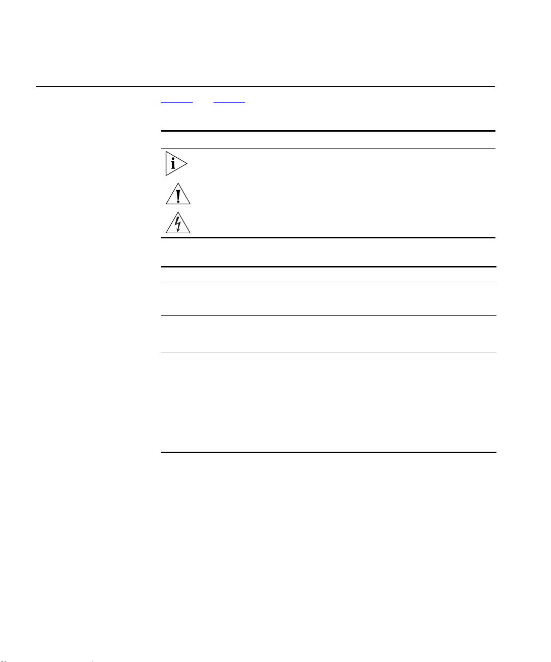
Conventions Table 1 and Table 2 list conventions that are used throughout this guide.
Table 1 N o tice Icons
Icon Notice Type Description
Information note Information that describes important features or
instructions.
Feedback about this
User Guide
Caution Information that alerts you to potential loss of data or
Warning Information that alerts you to potential personal injury.
potential damage to an application, system, or device.
Table 2 Text Conventions
Convention Description
The words “enter”
and “type”
Keyboard key names If you must press two or more keys simultaneously, the key
Words in italics Italics are used to:
When you see the word “enter” in this guide, you must type
something, and then press Return or Enter. Do not press Return or
Enter when an instruction simply says “type.”
names are linked with a plus sign (+). Example:
Press Ctrl+Alt+Del
Emphasize a point.
Denote a new term at the place where it is defined in the text.
Identify menu names, menu commands, and software button
names. Examples:
From the Help menu, select Contents.
Click OK.
Your suggestions are very important to us. They will help make our
documentation more useful to you. Please e-mail comments about this
document to 3Com at:
Please include the following information when commenting:
Document title
Document product number (on the title page)
Page 11
Conventions 9
Page number (if appropriate)
Example:
OfficeConnect ADSL Wireless 108Mbps 11g Firewall Router User Guide
Product Number 3CRWDR200A-75
Page 24
Do not use this e-mail address for technical support questions. For
information about contacting Technical Support, please refer to the Support
and Safety Information sheet.
Related Documentation In addition to this guide, each Router document set includes one Installation
Guide. This guide contains the instructions you need to install and configure
your Router.
Page 12

10 ABOUT THIS GUIDE
Page 13

1
INTRODUCING THE FIREWALL ROUTER
Welcome to the world of networking with 3Com®. In the modern business
environment, communication and sharing information is crucial. Computer
networks have proved to be one of the fastest modes of communication but,
until recently, only large businesses could afford the networking advantage.
The OfficeConnect
networks to the small office.
The products that compose the OfficeConnect range give you, the small office
user, the same power , flexibility, and protection that has been available only to
large corporations. Now, you can network the computers in your office,
connect them all to a single Internet outlet, and harness the combined power
of all of your computers.
®
product range from 3Com has changed all this, bringing
OfficeConnect ADSL Wireless 108Mbps 11g Firewall Router
The OfficeConnect ADSL W ireless 10 8Mbps 1 1g Firewall Ro uter is designed
to provide a cost-effective means of sharing a single broadband Internet
connection amongst several wired and wireless computers. The Router also
provides internet services with standardized mechanism; namely, NAT and
IPSec, etc. Thus, it further prevents anyone outside of your network from
seeing your files or damaging your computers. The Router also gives you
many administrative features such as scheduled internet access policies, web
content filter, and intrusion detections.
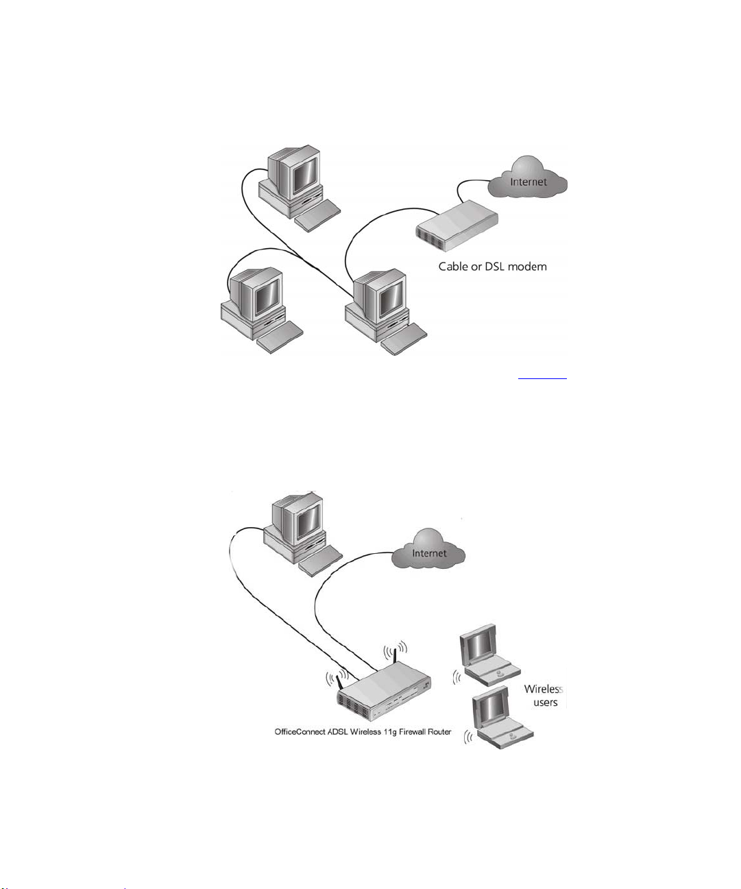
Figure 1
one computer is connected to the Internet. This computer must always be
powered on for the other computers on the network to access the Internet.
shows an example network without a Router. In this network, only
Page 14
12 CHAPTER 1: INTRODUCING THE FIREWALL ROUTER
Figure 1 Example Network Without a Firewall Router
When you use the Firewall Router in your network (Figure 2), it becomes
your connection to the Internet. Connections can be made directly to the
Router, or to an OfficeConnect Switch or Hub, expanding the number of
computers you can have in your network.
Figure 2 Example Network Using a ADSL Wireless 108Mbps 11g Firewall Router
Page 15

Firewall Router Advantages 13
Firewall Router Advantages
The advantages of the Firewall ADSL W irele ss 108Mbps 11g Firewall Router
include:
Shared Internet connection for both wired and wireless computers
High speed 802.11g wireless networking
No need for a dedicated, “always on” computer serving as your Internet
connection
Cross-platform operation for compatibility with Windows, Unix and
Macintosh computers
Easy-to-use, Web-based setup and configuration
Provides centralization of all network address settings (DHCP)
Acts as a Virtual server to enable remote access to Web, FTP, and other
services on your network
Security — Firewall protection against Internet hacker attacks and
encryption to protect wireless network traffic
Filtered access of inappropriate Web sites using the built-in URL filter
Internet Access Policy, to schedule your Internet Access ru les with options
in keywords and applications blocking
Wireless Multimedia, to maximize the quality of your internet service with
traffic prioritization
Package Contents The Firewall Router kit includes the following items:
One OfficeConnect ADSL Wireless 108Mbps 11g Firewall Router
One power adapter for use with the Firewall Router
Four rubber feet
One Ethern et cable
Page 16

14 CHAPTER 1: INTRODUCING THE FIREWALL ROUTER
One CD-ROM containing the Firewall Router Discovery program and this
User Guide
Installation Guide
One Support and Safety Information Sheet
One Warranty Flyer
If any of these items are missing or damaged, please contact your retailer.
Page 17
Minimum System and Component Requirements 15
Minimum System and
Component
Your Router requires that the computer(s) and components in your network be
configured with at least the following:
Requirements
A computer with an operating system that supports TCP/IP network ing
protocols (for example Windows 95/98/NT/Me/2000/XP, Uni x, Mac OS 8.5
or higher).
An Ethernet 10Mbps or 10/100 Mbps NIC for each computer to be
connected to the four-port switch on your Router.
An 802.11b or 802.11g wireless NIC.
A cable modem or DSL modem with an Ethernet port (RJ-45 connector).
An active Internet access account.
A Web browser that supports JavaScript, such as Netscape 4.7 or higher,
Internet Explorer 5.0 or higher, or Mozilla 1.2.1 or higher.
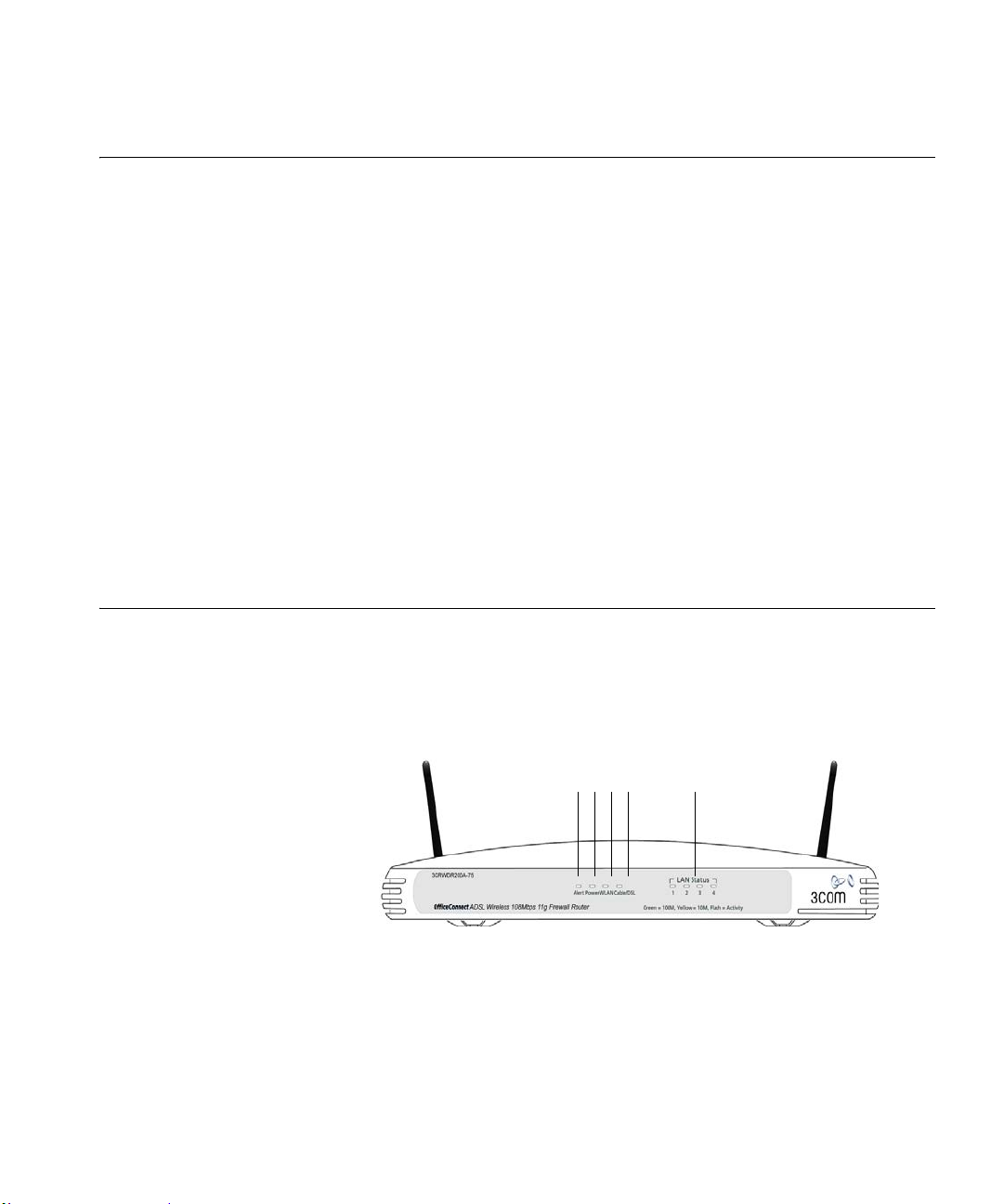
Front Panel The front panel of the Router contains a series of indicator lights (LEDs) that
help describe the status of various networking and connection operations.
Figure 3 Router - Front Panel
4
5
12 3
1 Alert LED
Orange
Indicates a number of different conditions, as described below.
Off - The Router is operating normally.
Flashing quickly - Indicates one of the following conditions:
The Router has just been started up and is running a self-test routine, or
Page 18

16 CHAPTER 1: INTRODUCING THE FIREWALL ROUTER
The administrator has invoked the Reset to Factory Defaults command, or
The system software is in the process of being upgraded
In each of these cases, wait until the Router has completed the current
operation and the alert LED is Off.
Flashing slowly - The Router has completed the Reset to Factory Defaults
process, and is waiting for you to reset the unit. To do this, remove power,
wait 10 seconds and then re-apply power. The Router will then enter the
start-up sequence and resume normal operation.
If you have used a cable to reset the unit to Factory Defaults, See "Reset to
Factory Default" on page 69.
On for 2 seconds, and then off - The Router has detected and prevented a
hacker from attacking your network from the Internet.
Continuously on - A fault has been detected with your Router during the
start-up process. Refer to Chapter 6
“Troubleshooting”.
2Power LED
Green
Indicates that the Router is powered on.
3 Wireless LAN (WLAN) Status LED
Yellow
If the LED is on it indicates that wireless networking is enabled. If the LED is
flashing, data is being transmitted or received. If the LED is off, the Wireless
LAN has been disabled in the Router, or there is a problem. Refer to
Chapter 6
“Troubleshooting”.
4 F our LAN Status LEDs
Green (100 Mbps link) / yellow (10 Mbps link)
If the LED is on, the link between the port and the next piece of network
equipment is OK. If the LED is flashing, the link is OK and data is being
transmitted or received. If the LED is off, noth ing is co nnected, the connec ted
device is switched off, or there is a problem with the connection (refer to
Chapter 6
“Troubleshooting”). The port will automatically adjust to the
correct speed and duplex.
5 Cable/DSL Status LED
Page 19
Rear Panel 17
Green (100 Mbps link) / yellow (10 Mbps link)
If the LED is on, the link between the Router and the cable or DSL modem is
OK. If the LED is flashing, the link is OK and data is being transmitted or
received. If the LED is off, nothi ng is connected, the modem is swit ched off or
there is a problem (refer to Chapter 6
“Troubleshooting”).
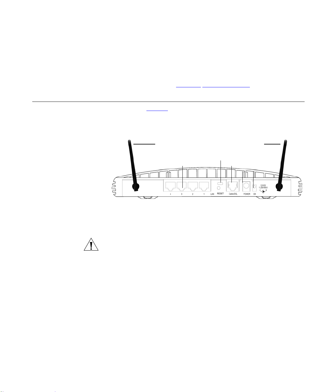
Rear Panel The rear panel (Figure 4) of the Router contains four LAN ports, one Ethernet
Cable/DSL port, a power adapter OK LED, and a power adapter socket.
Figure 4 Router - Rear Panel
6
11
10
7
89
6 Wireless Antennae
The antennae on the product should be placed in a ‘V’ position when initially
installed.
CAUTION: Do not force the antennae beyond their mechanical stops.
Rotating the antennae further may cause damage.
7ADSL port
Using the RJ11 cable provided, you should connect your Router to the
telephone socket via a splitter.
8 Power Adapter Socket
Only use the power adapter supplied with this Router. Do not use any other
adapter.
9 Power Adapter OK LED
Green
Indicates that the power adapter is supplying power to the Router. If the LED
is off, there may be a problem with the power adapter or adapter cable.
Page 20

18 CHAPTER 1: INTRODUCING THE FIREWALL ROUTER
10 Reset Button
Press this button for resetting your Router to factory default.
11 Four 10/100 LAN ports
Using suitable RJ-45 cable, you can connect your Router to a computer, or to
any other piece of equipment that has an Ethernet connection (for example, a
hub or a switch). The LAN ports will automatically set themselves to MDI or
MDIX depending on the device to which they are connected and the type of
cable used.
Page 21
HARDWARE INSTALLATION
2
Introduction This chapter will guide you through a basic installation of the Router,
including:
Connecting the Router to the Internet.
Connecting the Router to your network.
Setting up your computers for networking with the Router.
Safety Information
Positioning the Router
WARNING: Please read the Router section in Appendix C
VORSICHT: Bitte lesen Sie den Abschnitt “Wichtige Sicherheitshinweise”
sorgfältig durch, bevor Sie das Gerät einschalten.
AVERTISSEMENT: Veuillez lire attentivement la section “Consignes
importantes de sécurité” avant de mettre en route.
You should place the Router in a location that:
is conveniently located for connection to the cable or DSL modem that
will be used to connect to the Internet.
is centrally located to the wireless computers that will connect to the
Router . A suita ble l ocation might be on top of a h igh shelf or si milar furniture
to optimize wireless connections to computers in both horizontal and vertical
directions, allowing wider coverage.
allows convenient connection to the computers that will be connected to
the four LAN ports on the rear panel, if desired.
before you start.
Page 22
20 CHAPTER 2: HARDWARE INSTALLATION
allows easy viewing of the front panel LED indicator lights, and access to
the rear panel connectors, if necessary.
When positioning your Router, ensure:
It is out of direct sunl ight and away from sources of heat.
Cabling is away from p ower l in es, fluorescent lighting fixtures, and
sources of electrical noise such as radios, transmitters and broadband
amplifiers.
Water or moisture cannot enter the case of the unit.
Air flow around the unit and through the vents in the side of the case is not
restricted. 3Com recommends you provide a minimum of 25 mm (1 in.)
clearance.
Using the Rubber Feet Use the four self-adhesive rubber feet to prevent your Router from moving
around on your desk or when stacking with other flat top Offic eConnect units.
Only stick the feet to the marked areas at each corner of the underside of your
Router.
Stacking the Router If you are stacking your Router with other OfficeConnect units, install the
Router at the top of the stack. Refer to the documentation supplied with your
other OfficeConnect unit for details on using the stacking clip.
A stacking clip is not supplied with the Router. Use the stacking clip supplied
with another stackable OfficeConnect unit.
Wall Mounting There are two slots on the underside of the Router that can be used for wall
mounting.
When wall mounting the unit, ensure that it is within reach of the power outlet.
You will need two suitable screws to wall mount the unit. To do this:
1 Ensure that the wall you use is smooth, flat, dry and sturdy and make two
screw holes which are 150 mm (5.9 in.) apart.
2 Fix the screws into the wall, leaving their heads 3 mm (0.12 in.) clear of the
wall surface.
Page 23
Before you Install your Router 21
3 Remove any connections to the unit and locate it over the screw heads. When
in line, gently push the unit on to the wall and move it downwards to secure.
When making connections, be careful not to push the unit up and off the
wall.Router
CAUTION: Only wall mount single units, do not wall mount stacked units.
Before you Install your Router
Before you install and configure your Router, you need the following
additional information. If you do not have this information, contact your
Internet Service Provider (ISP). Space is provided below for you to record this
information.
If you have a DSL connection and your ISP allocates IP information
dynamically, you need a User Name and Password:
User Name : ______________________
Password : ______________________
Service Name : ______________________
Authentication Method : ______________________
You only need a PPPoE Service Name if your ISP requires one. Do not enter
anything if your ISP does not require this information.
You should leave the Authentication Method as its default: Auto if your ISP
doesn’t specify this parameter.
Page 24
22 CHAPTER 2: HARDWARE INSTALLATION
If your ISP allocates fixed or static IP information, you need the following
information:
IP Address : ____.____.____.____
Subnet Mask : ____.____.____.____
Default Router address : ____.____.____.____
DNS address : ____.____.____.____
If your ISP allocates IP information dynamically over a protocol other than
PPPoE, you do not need any further information. This configuration is typical
of cable connections.
Powering Up the Router
Connecting the Router
To power up the Router:
1 Plug the power adapter into the power adapter socket located on the back
panel of the Router.
2 Plug the power adapter into a standard electrical wall socket.
The first step for installing your Router is to physically connect it to a RJ11
cable with the splitter and then co nnect the Router t o a computer in order to be
able to access the Internet. See Figure 5
:
Page 25
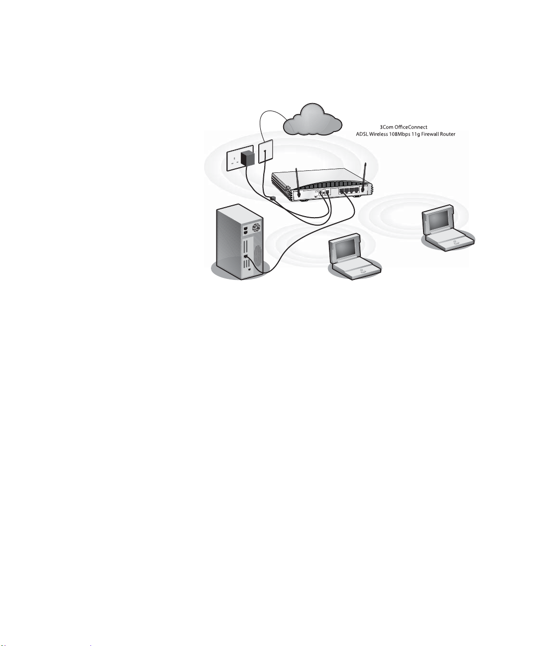
Figure 5 Connecting the Router
Connecting the Router 23
Telephone
socket
Joufsofu
2
1
5
2
.
1
C
D
V
X
A
M
A
L
S
D
/
e
l
b
a
C
K
O
R
E
W
O
P
N
A
L
1
2
3
4
Xjsfmftt!
Vtfst
Power
Supply Unit
Zpvs!QD
To use your Router to connect to the Internet through an DSL connec ti on :
1 Insert one end of the supplied telephone (RJ-11) cable into the Cable/DSL
port on the rear panel of the Router. Check that the DSL Sync status LED
lights on the Router.
2 Connect your computer to one of the four LAN ports on the Rout er using a
Category 5 twisted pair cable. Check that the correspond ing LAN sta tus LED
on the Router lights.
You have now completed the hardware installation of your Router. Next you
need to set up your computers so that they can make use of the Router to
communicate with the Internet.
3Com recommends that you perform the initial Router configurat ion from a
computer that is directly connected to one of the LAN ports.
If you configure the Router from a wireless computer, note that you may lose
contact with the Router if you change the wireless configuration.
T o communicate wirelessly with your Router, your wireless NIC should be set
as follows:
Encryption — none
Page 26

24 CHAPTER 2: HARDWARE INSTALLATION
Service Area Name/SSID — 3Com
Channel — 11
Page 27

3
SETTING UP YOUR COMPUTERS
The Router has the ability to dynamically allocate network addresses to the
computers on your network, using DHCP. However, your computers need to
be configured correctly for this to take place. To change the configuration of
your computers to allow this, follow the instructions in this chapter. If your
computers are configured with fixed or static addresses and you do not wish to
change this, then you should use the Discovery program on the Router
CD-ROM to detect and configure your Router. Refer to Appendix A
information on using the Discovery program.
for
Obtaining an IP Address Automatically
Windows 2000 If you are using a Windows 2000-based computer, use the following
Refer to the section below which relates to your operating system for details
on how to obtain an IP address automatically.
procedure to change your TCP/IP settings:
1 From the Windows Start Me nu, select Settings > Control Panel.
2 Double click on Network and Dial-Up Connections.
3 Double click on Local Area Connection.
4 Click on Properties.
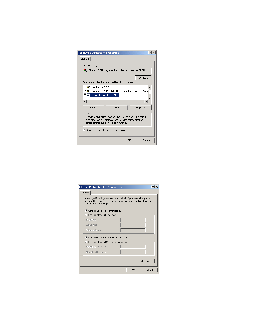
5 A screen similar to Figure 6
TCP/IP and click on Properties.
should be displayed. Select Internet Protocol
Page 28
26 CHAPTER 3: SETTING UP YOUR COMPUTERS
Figure 6 Local Area Properties Screen
6 Ensure that the options Obtain an IP Address automatically, and Obtain DNS
server address automatically are both selected as shown in Figure 7
OK.
. Click
Figure 7 Internet Protocol (TCP/IP) Properties Screen
7 Restart your computer.
Page 29

Obtaining an IP Address Automatically 27
Windo ws XP If you are using a Windows XP computer, use the following procedure to
change your TCP/IP settings:
1 From the Windows Start menu, select Control Panel.
2 Click on Network and Internet Connections.
3 Click on the Network Connections icon.
4 Double click on LAN or High Speed Connection icon. A screen titled Local
Area Connection Status will appear.
5 Select Internet Protocol TCP/IP and click on Properties.
6 Ensure that the options Obtain an IP Address automatically, and Obtain DNS
servers automatically are both selected. Click OK.
7 Restart your computer.
Windows 95/98/ME If you are using a Win dows 95 /9 8/ME computer, use th e fo llo w ing p roce du re
to change your TCP/IP settings:
1 From the Windows Start Menu, select Settings > Control Panel.
2 Double click on Network. Select the TCP/IP item for your network card and
click on Properties.
3 In the TCP/IP dialog, select the IP Address tab, and ensure that Obtain IP
address automatically is selected. Click OK.
Macintosh If you are using a Macintosh computer, use the following procedure to change
your TCP/IP settings:
1 From the desktop, select Apple Menu, Control Panels, and TCP/IP.
2 In the TCP/IP control panel, set Connect Via: to “Ethernet”.
3 In the TCP/IP control panel, set Configure: to “Using DHCP Server.”
4 Close the TCP/IP dialog box, and save your changes.
5 Restart your computer.
Page 30
28 CHAPTER 3: SETTING UP YOUR COMPUTERS
Disabling PPPoE and PPTP Client Software
If you have PPPoE or PPTP client software installed on your computer, you
will need to disable it. To do this:
1 From the Windows Start menu, select Settings > Control Panel.
2 Double click on Internet Options.
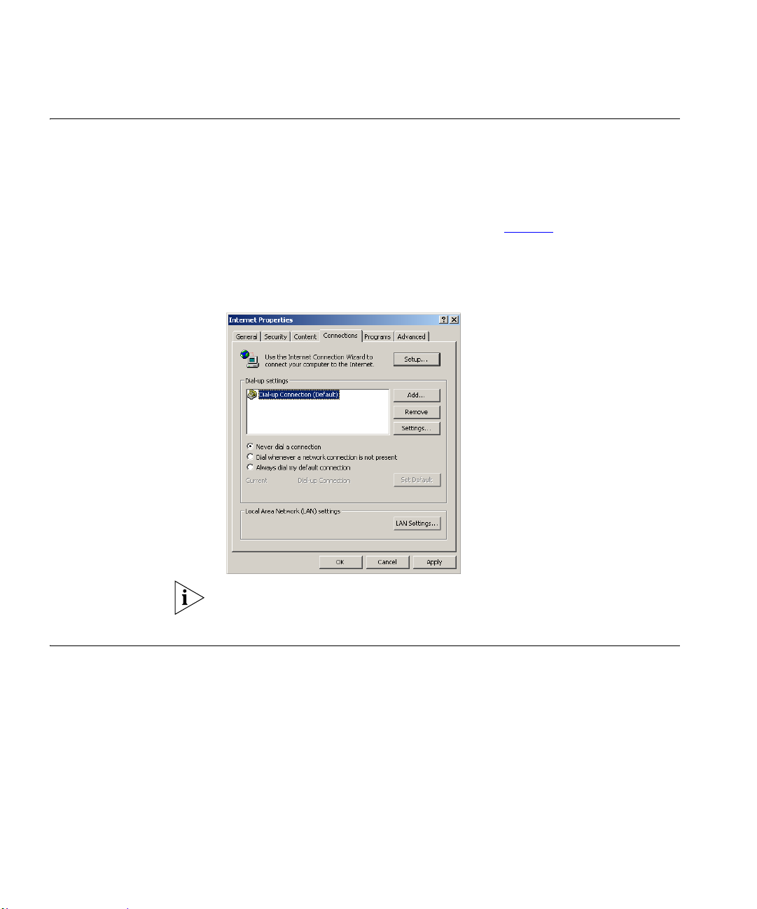
3 Select the Connections T ab . A screen simila r to Figure 8
4 Select the Never Dial a Connection option.
Figure 8 Internet Properties Screen
should be displayed.
Y ou may wish to remove the PPPoE client software from your computer to free
resources, as it is not required for use with the Router.
Disabling Web Proxy Ensure that you do not have a web proxy enabled on your comp uter.
Go to the Control Pane l and click on Internet Options. Select the Connections
tab and click LAN Settings at the bottom. Make sure that the Use Proxy Server
option is unchecked.
Page 31
RUNNING THE SETUP WIZARD
4
Accessing the Wizard The Firewall Router set up program is Web-based, which means that it is
accessed through your Web browser (Netscape Navigator 4.7 or higher,
Internet Explorer 5.0 or higher, or Mozilla 1.2.1 or higher).
To use the Setup Wizard:
1 Ensure that you have at least one computer connected to the Firewal l Rou ter.
Refer to Chapter 2
2 Launch your Web browser on the computer.
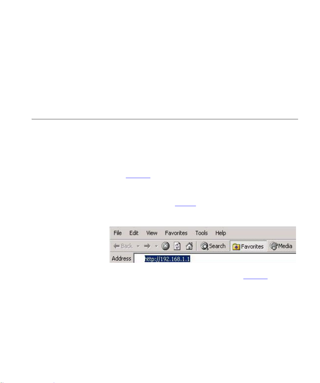
3 Enter the following URL in the location or address field of your browser:
http://192.168.1.1 (Figure 9
Figure 9 Web Browser Location Field (Factory Default)
for details on how to do this.
). The Login screen displays.
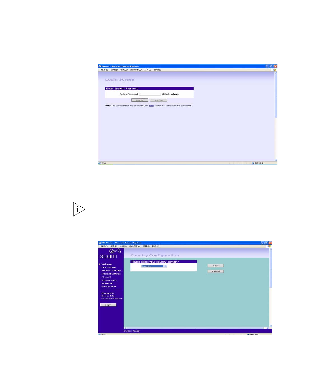
4 To log in as an administrator, enter the password (the default setting is
admin) in the System Password field and click Log in (Figure 10
).
Page 32
30 CHAPTER 4: RUNNING THE SETUP WIZARD
Figure 10 Firewall Router Login Screen
5 If the password is correct, the Country Selection screen will appear. Select the
country you wish to configure the Firewall Router for, then click Apply.
(Figure 11
)
If your purchased your Firewall Router in the United States, you do not see
this screen, as it is automatica lly set.
Figure 11 Country Selection Screen
Page 33
Accessing the Wizard 31
6 When you have selected a country either:
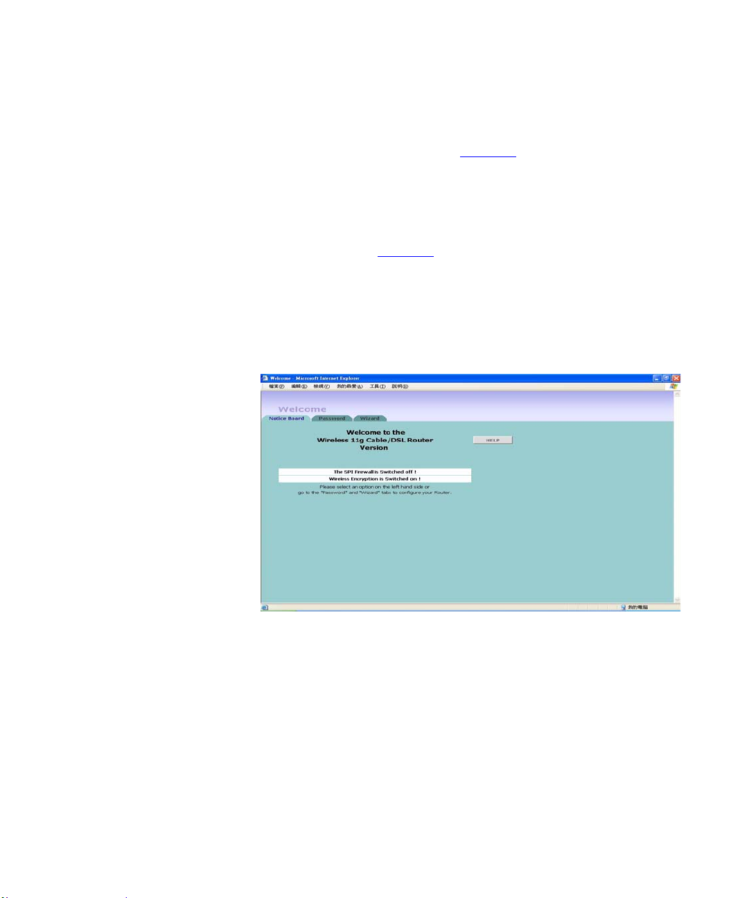
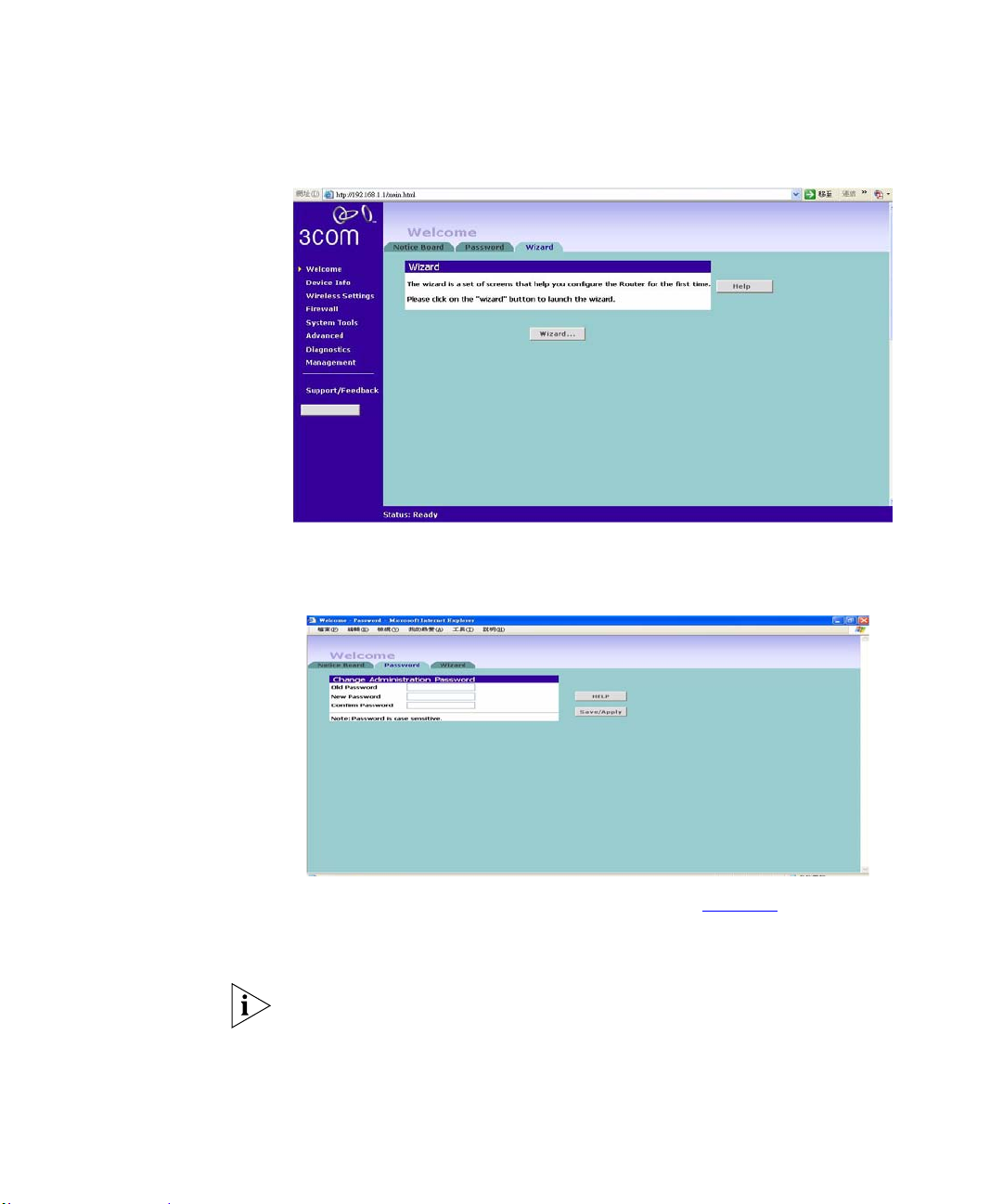
The Welcome screen will appear (Figure 12). Select the Wizard tab and
click Wizard.
or
If your Router has not been configured before, the Wizard will launch
automatically (refer to Figure 13
).
7 Click Next.
8 You will be guided step by step th ro ug h a basic setup procedure.
Figure 12 Welcome Screen
Page 34
32 CHAPTER 4: RUNNING THE SETUP WIZARD
Figure 13 Wizard Screen
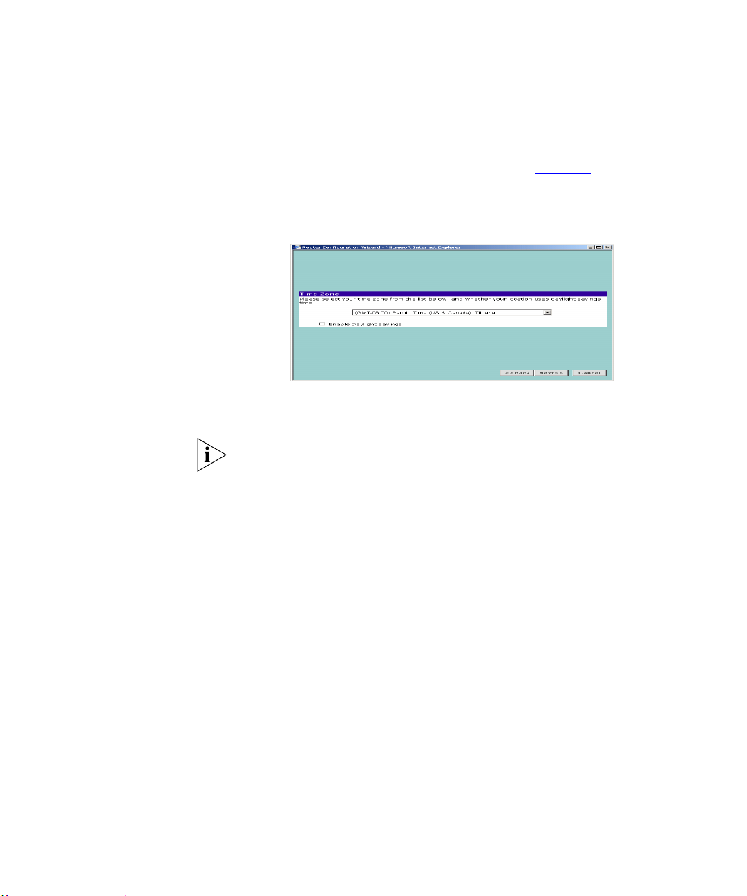
Password Figure 14 Change Administration Password Screen
When the Change Administration Password screen (Figure 14) appears, type
the Old Password, then a new password in both the New Password and
Confirm Password boxes.
3Com recommends entering a new password when setting up the Firewall
Router for the first time. The Firewa ll Rout er is ship ped from the factory with
a default password, admin.
1. Password is case sensitive.
Page 35
Accessing the Wizard 33
2. Write the new password down and keep it in a safe place, so that you can
change your settings in the future.
Time Zone
ATM PVC
Configuration
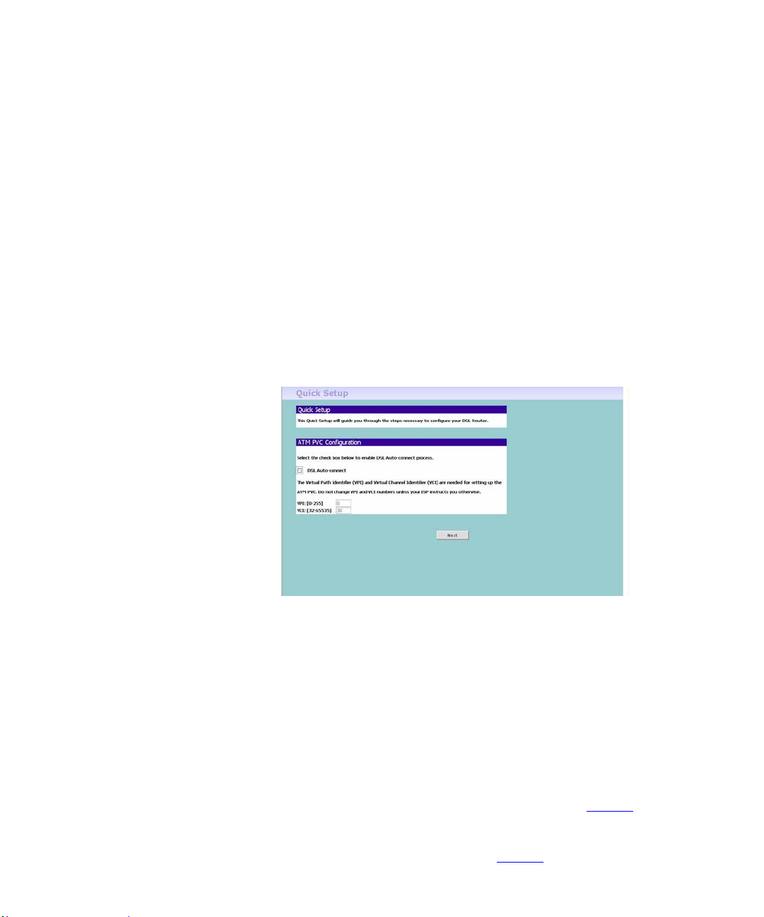
Click Next to display the Time Zone setup screen (Figure 15
Figure 15 Time Zone Screen
).
Select your time zone from the pull-down menu, check the daylight savings
option if required, and then click Next.
The Daylight Savings option advances the system clock by one hour. It does
not cause the system clock to be updated for daylight savings time
automatically.
VPI stands for Virtual Path Identifier - contained in the ATM cell header to
designate the virtual path on the physical ATM link.
VCI stands for Virtual Channel Identifier - 16-bit field in the header of an
ATM cell. The VCI, together with the VPI, is used to identify the next
destination of a cell as it passes through a series of ATM switches on its way
to its destination.
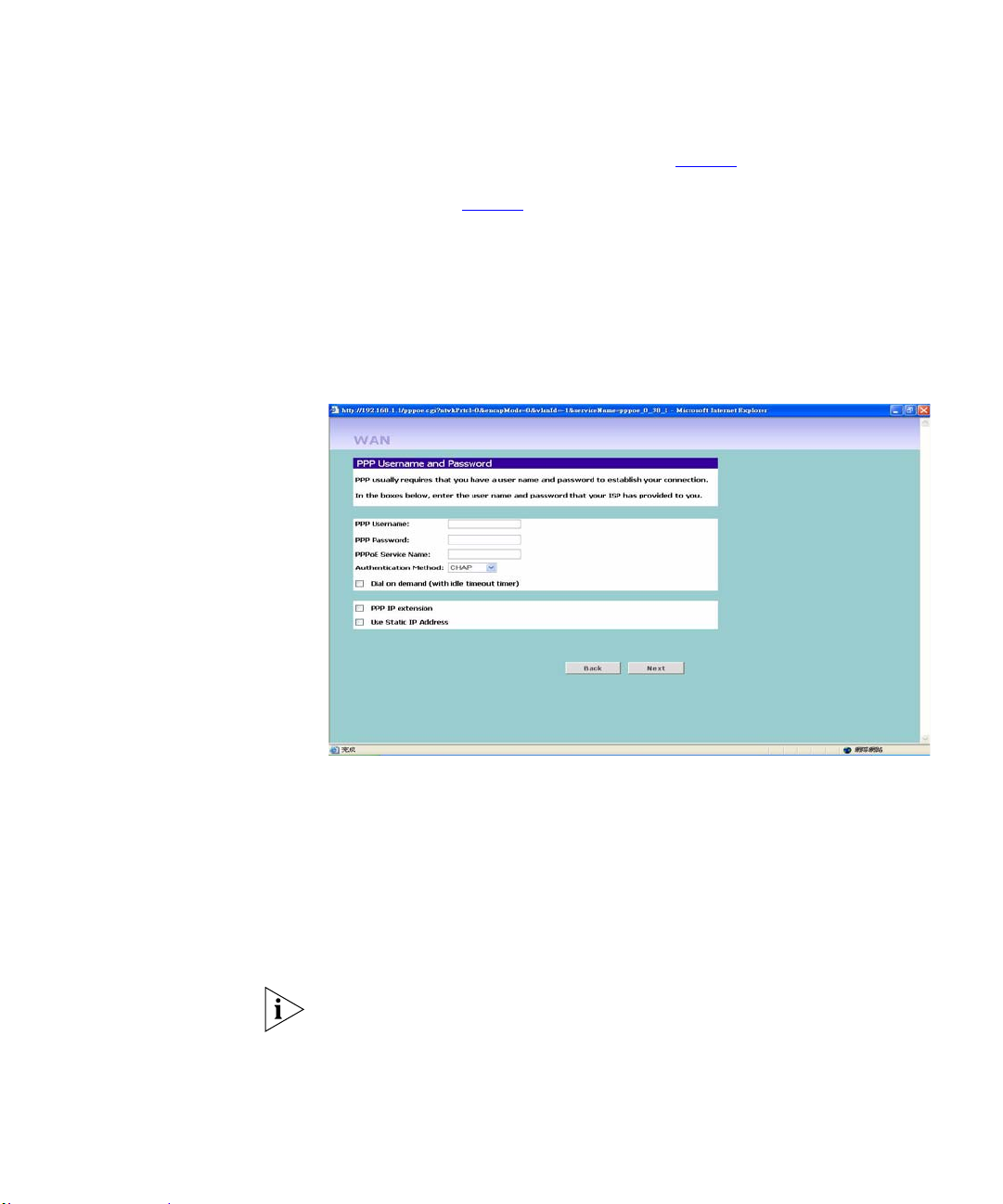
You may select on DSL Auto-connect or enter the values for VPI and VCI.
Quality of Service
Select the type of QoS from the drop-down list:
UBR (Unspecified Bit Rate) with/without PCR (Peak Cell Rate): the UBR
service class is intended for delay-tolerant or non-real-time applications, for
example, those which do not require tightly constrained del ay and delay
variation, such as traditional computer communications applications. The
Page 36
34 CHAPTER 4: RUNNING THE SETUP WIZARD
UBR service may be considered as "best effort service". Peak cell rate
specifies the maximum cell rate at which the user will transmit.
CBR (constant bit rate): the CBR service class is intended for real-time
applications, for example, those requiring tightly constrained delay and delay
variation, such as voice and video applicatio ns. The consistent availabilit y of a
fixed quantity of bandwidth is considered appropriate for CBR service.
VBR (Variable Bit Rate) is subdivided into a real time (RT) class and
non-real time (NRT) class. VBR (RT) is used for connections in which there is
a fixed timing relationship betw een samples. VBR (NRT) is used for
connections in which there is no fixed timing relationship between samples,
but that still need a guaranteed QoS. Typical VBR sources are compressed
voice and video. These applications require small delay variations.
Figure 16 The ATM Configuration screen
IGMP IGMP stands for Internet Group Management Protocol which is defined in
RFC 1112 as the standard for IP Multicast.
Select to enable IGMP multicast.
Select to enable WAN service and enter the service name to identify your
internet service.
Connection Mode Select an Internet Addressing mode from the following:
PPPoE/PPPoA is required (typically DSL users only) see page 35
IP over ATM (IPoA, using ATM networks as the underlying data link for
IP networks, defined by IETF RFC 1577) see page 37
Page 37
MAC Encapsulation Routing (MER) see page 36
Bridging, see page 38
and click Next.
PPPoE/PPPoA Mode
Figure 17 PPPoE Screen
Accessing the Wizard 35
T o setup the Firewall Router for use with a PPP over Ethernet (PPPoE) or PPP
over ATM (used mainly in UK) connection, use the following procedure:
1 Enter your PPP over Ethernet/ATM user name in the PPPoE/PPPoA User
Name text box.
2 Enter your PPP over Ethernet/A TM password in the PPPoE/PPPoA Passwor d
text box.
3 Enter your PPP over Ethernet/ATM service name in the PPPoE/PPPoA
Service Name text box.
Do not enter anything in this box if your ISP does not require a service name.
4 Select PPP Authentication Method from the drop-down menu.
5 Dial on Demand: Check the box to make a connection while in demand. Enter
T
the Inactivity
imeout to cut off the network connection if there is no activity
for this router.
Page 38
36 CHAPTER 4: RUNNING THE SETUP WIZARD
6 PPP IP extension: Check this box to invoke the PPP IP extension. Only one
user is allowed to access the web configurator at one time when this is
checked.
7 Use Static IP Address: Check this box to enter the IP Address manually.
Check all of your settings, and then click Next.
Enable 802.1q
Check on this to enable this function. The 802.1q standard defines the VLAN
protocol which allows insertion of a 4-byte identifier into the ethernet frame
format to identify the VLAN to which the frame belongs. Configuring
VLANs helps control the size of the broadcast domain and keeps local traffic
local.You can configure the router to router traffic to the appropriate
destination VLAN. To specify a VLAN interface, enter the Vlan-id in the
field.
MER Mode
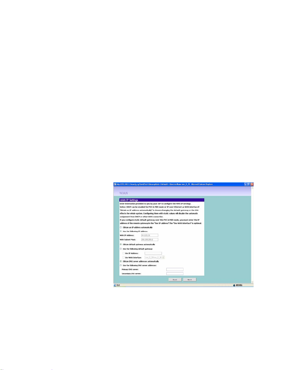
Figure 18 MER screen
MER mode is used in business environment where static IP address and
subnet are assigned by your ISP. Choose MER and click Next.
To setup the Firewall Router for use with a MER connection, use the
following procedure:
Obtain an IP address automatically: Click this button to make the system get
an IP address automatically.
Page 39
Accessing the Wizard 37
Manually entering an IP address: To set WAN IP address by yourself.
1 WAN IP Address: Enter the IP address for using in the WAN from your ISP.
2 WAN Subnet Mask: Enter the WAN subnet mask.
3 Default Gateway: Enter the default gateway for using in the WAN from your
ISP.
4 Enter your primary DNS address in the Primary DNS Address text box.
5 Enter your secondary DNS address in the Secondary DNS Address text box.
6 Check all of your settings, and then click Next or back to go back to the
pervious screen.
7 Configuring LAN setting: See “
LAN Settings” in this section for more
information.
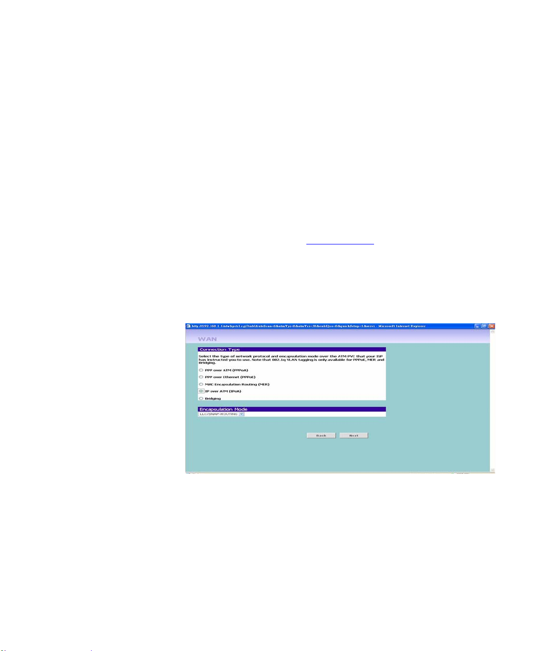
IPoA Mode
Figure 19 IPoA Mode Screen
To setup the Firewall Router for use with a IPoA connection, use the
following procedure:
1 Enter the IP Address for WAN interface.
2 Enter the Subnet Mask for WAN interface.
3 Enter your Primary DNS Address and Secondary DNS address.
Your ISP may provide you wi th primary and secondary DNS addresses. If
they have been provided, enter the addresses in the appropriate text boxes. If
not, leave 0.0.0.0 in the boxes.
Page 40
38 CHAPTER 4: RUNNING THE SETUP WIZARD
4 Enable NAT: Check the Enable NAT to enable this function which will allow
more than one PC in the LAN to connect the internet.
5 Click on Next to configure your LAN settings. See “
LAN Settings” in this
section for more information.
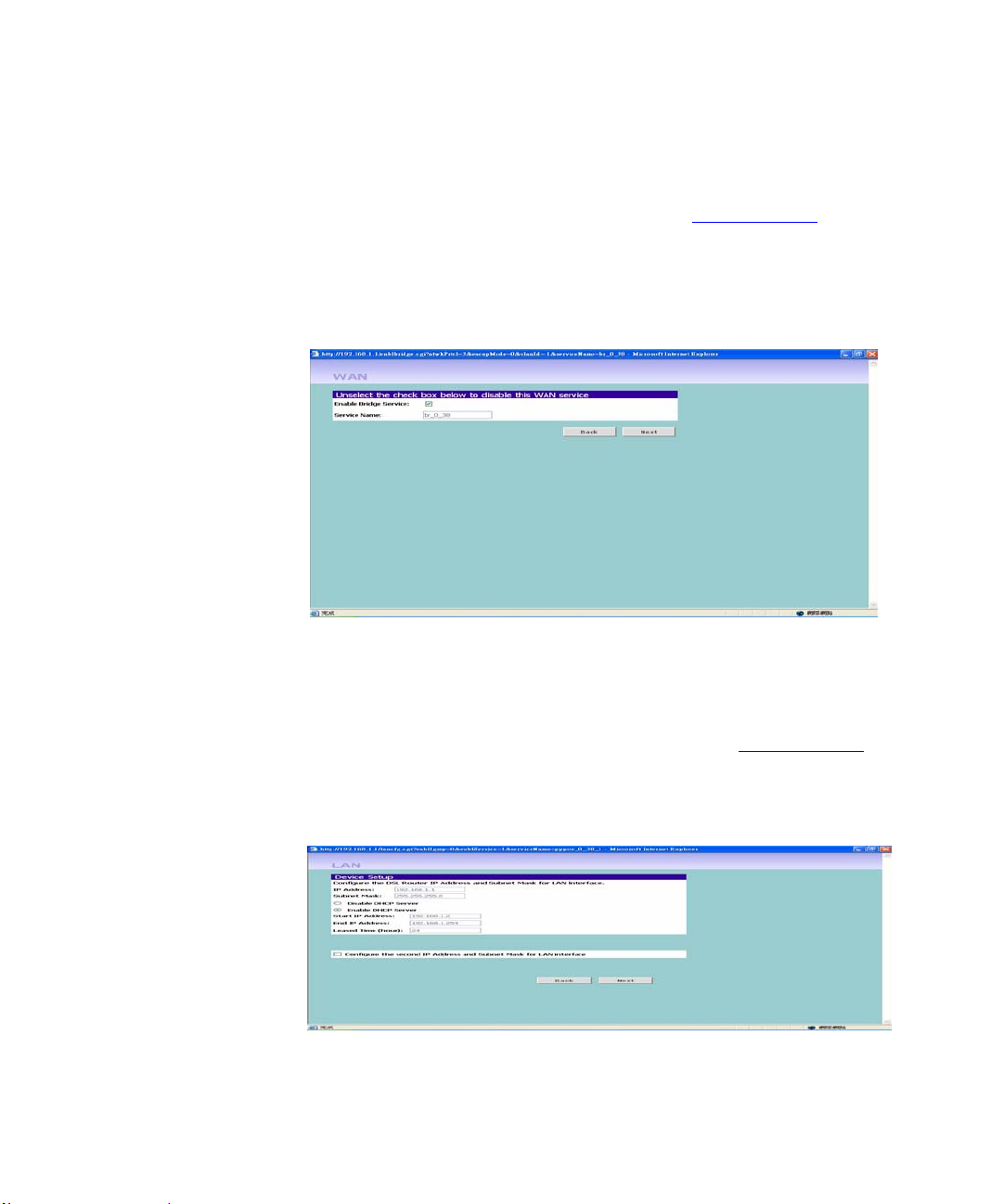
Bridging Mode
Figure 20 Bridging Mode Screen
To set up the Firewall Router for use as a bridge in which the router is the
bridge between WAN and LAN, use the following procedure:
1 Enter your the name for the bridging service.
2 Enter the IP Address and Subnet Mask for t he LAN. See “
LAN Settings”
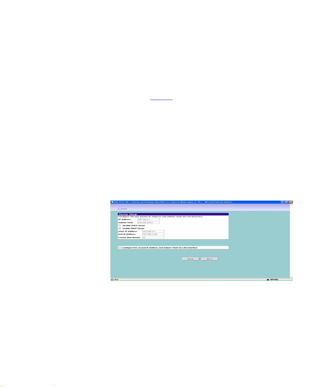
LAN Settings Figure 21 LAN IP Address Screen
Page 41
Accessing the Wizard 39
This screen displays a suggested LAN IP address and subnet mask of the
Firewall Router. It also allows you to change the IP address and subnet mask.
1 Primary IP Address: Enter the first IP Address for your LAN interface.
2 Subnet Mask: Enter the Subnet Mask for your LAN interface.
3 Enable DHCP server on the LAN: Check this box to enable the DHCP service
on the router. See “
DHCP” in this section.
4 Configure the second IP Address and Subnet Mask for the LAN interface:
Check this box to make another set of IP Address and Subne t Mask to conn ect
to your router if they are not included in the range of DH CP server.
5 Enter the Secondary IP Address and Subnet Mask.
DHCP
The Firewall Router contains a Dynamic Host Configuration (DHCP) server
that can automatically configure the TCP/IP settings of every computer on
your network.
Figure 22 DHCP Server Setup Screen
To activate the DHCP Server option, select Enable the DHCP server with the
following settings: Enter the start and end IP Address of your DHCP range.
Enter the leased time in hour to specify the frequency for DHCP
assignment.Check the Enable DHCP Server Relay to forward the DHCP
request to another server. Enter the IP Address of the designated server.
Page 42
40 CHAPTER 4: RUNNING THE SETUP WIZARD
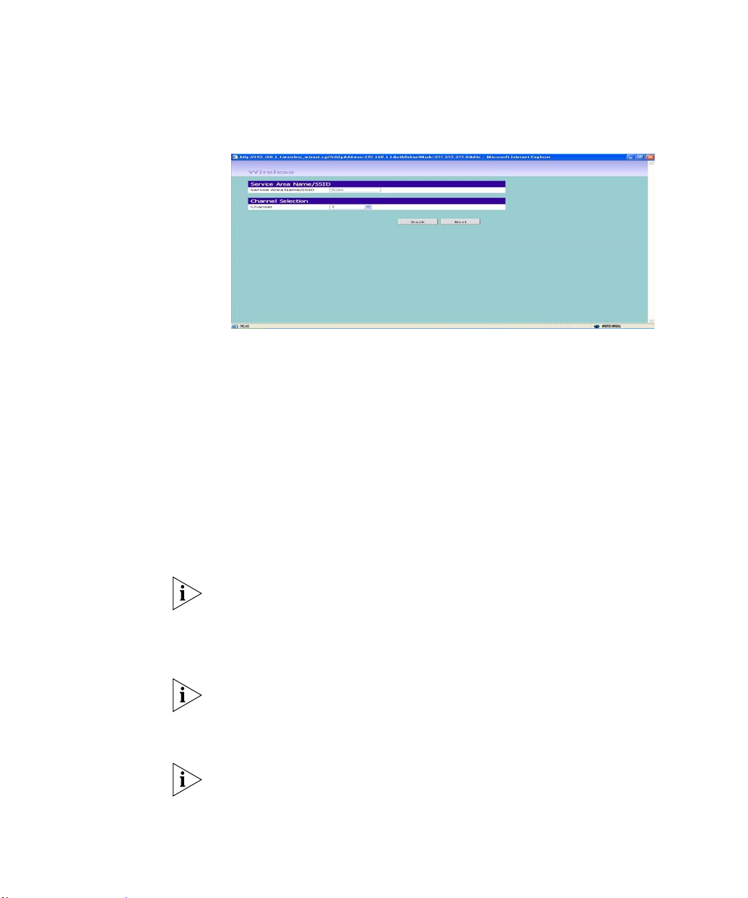
Wireless Settings Figure23 Wireless Configuration Screen
This screen displays the Channel and Service Area Name. It also al lows you
to change these settings. There are a maximum of 14 channels, the number
available to you is dependent on the country you reside in. Selecting Clear
Channel Select from the Channel drop-down list allows the Firewall Router to
automatically select an available channel when first powered on.
The Service Area Name default for 3Com products is “3Com”. Up to 32 (case
sensitive) characters can be entered for the Service Area Name.
3Com strongly recommends that you change the SSID to something ot her
than the default.
Click Next when you have finished.
If you are configuring the Firewall Router from a wir eless computer any
changes you make to the wireless configuration will result in communication
between the Firewall Router and your computer being lost. This is why 3Com
strongly recommends that you configure the Firewall Router from a wired
computer.
It is very important that you set up your wireless clients to use the same
Service Area Name or SSID as the one you use on this screen. If your clients
use a different Service Area Name then they will not be able to communicate
with the Firewall Router.
The choice of channel is less important as Clients will generally search all of
the available channels. You should however make a note of the channel you
select as this may be useful if you experience problems with your clients.
Page 43
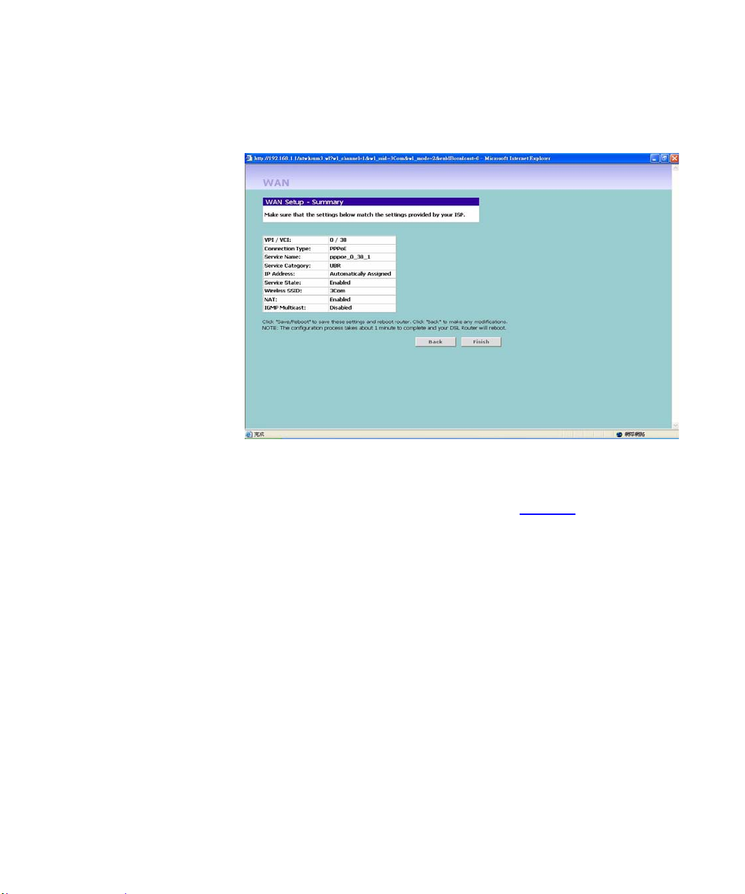
Summary Figure 24 Configuration Summary Screen
Accessing the Wizard 41
When you complete the Setup Wizard, a configuration summary will display.
3Com recommends that you verify the configuration informa tio n of the
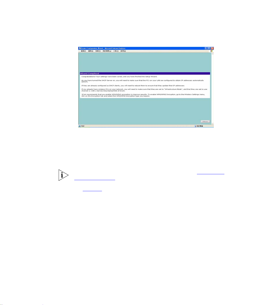
Firewall Router and then print this page for your records. Click Finish to
display the Wizard completed screen, shown in Figure 25
Page 44
42 CHAPTER 4: RUNNING THE SETUP WIZARD
Figure 25 Wizard Completed Screen
If you have made changes to the LAN Settings or wireless configuration
options, you may need to reconfigure the computer you are using in order to
make contact with the Firewall Router again.
Your Firewall Router is now configured and ready for use.
For information on improving your Wireless network security see "Wireless
Settings" on page 48.
See Chapter 5 for a detailed description of the Router configuration screens.
Page 45

5
ROUTER CONFIGURATION
Navigating Through the Router Configuration Pages
Main Menu At the left side of all screens is a main menu, as shown in Figure 26
This chapter describes all the screens available through the Router
configuration pages, and is provided a s a reference. To get to the configuration
pages, browse to the Router by entering the URL in the location bar of your
browser. The default URL is http://192.168.1.1 but if you changed the Router
LAN IP address during initial configuration, us e the new IP address instead.
When you have browsed to the Router, log in using your system password
(default admin).
on
page 45
in the main part of the screen.
Welcome — displays the firmware version of the Router, allows you to
change your password, and launch the Wizard
LAN Settings — allows you to configure the LAN interface and view the
leased DHCP list.
Wireless Settings — enables /disables access from wireless computers,
configures WPA or WEP encryption, provides facilities for improving the
security of the wireless network, setup WMM parameters, Wireless mode
selection, and Advanced Wireless Settings.
Internet Settings — let you set up the WAN (Wide Area Network) ie. DSL
Moden connection.
. When you click on a topic from the main menu, that page will appear
Firewall — allows configuration of the Router’s firewall features: Virtual
Servers, Special Applications, DMZ Hosts, SPI options, Internet Access
Policy, and Content Filtering.
System Tools — allows the administrator to perform maintenance
activities on the Router.
Page 46

44 CHAPTER 5: ROUTER CONFIGURATION
Advanced — allows you to monitor and configure the Router’s advanced
features, including LAN/WAN setup, DSL, RIP, DDNS, Print Server, IPSec,
Certificate, Proxy ARP, and ALG.
Management — displays the current status and activity logs of the Router,
SNMP enable/disable, Internet service enable/disable, and remote
management control.
Diagnostics — Testing the connection between your wired and wireless
device to your Router.
Device Info — Providing the configuration summary and statistics on your
LAN/WAN/ATM/ADSL connection.
Support/Feedback — contains a comprehensive online help system and
allows you to provide 3Com with feedback on your Router.
Option Tabs Each corresponding menu page may also provide sub-sections which are
accessed through the use of tabs (see Figure 26
sub-section, simply click on the required tab.
for example). To access a
Getting Help
On every screen, a Help button is available which provides access to the
context-sensitive online help system. Click Help for further assistance and
guidance relating to the current screen.
Welcome Screen The Welcome section allows you to view the Notice board and to change your
Password. You can also gain access to the Configuration Wizard. (See
Accessing the Wizard” on page 29 for details).
“
Page 47
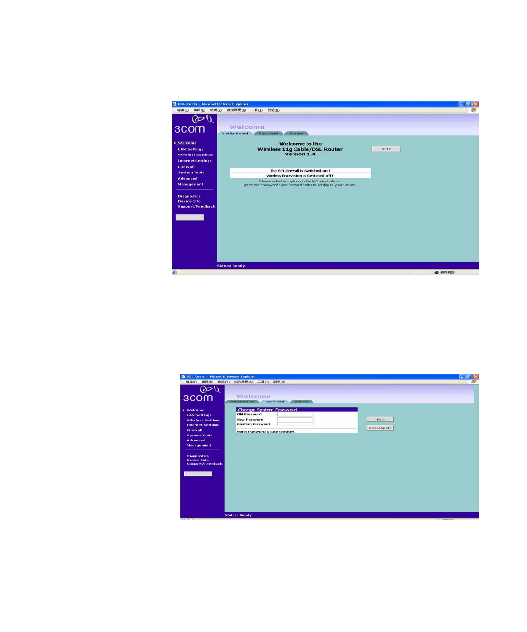
Notice Board Figure 26 Notice Board Screen
The Notice Board is used to display the firmware version and configuration
warning messages. For example, you would be warned if you had disabled
wireless networking or wireless encryption.
Welcome Screen 45
Password
Figure 27 Password Screen
Page 48
46 CHAPTER 5: ROUTER CONFIGURATION
Changing the Administration Password
You can change the password to prevent unauthorized access to the
Administration System. To do this:
1 Enter the current password in the Old Password field
2 Enter the new password in the New Password field
3 Enter the new password again in the Confirm Password field
4 Click Save/Apply to save the new password
The password is case sensitive.
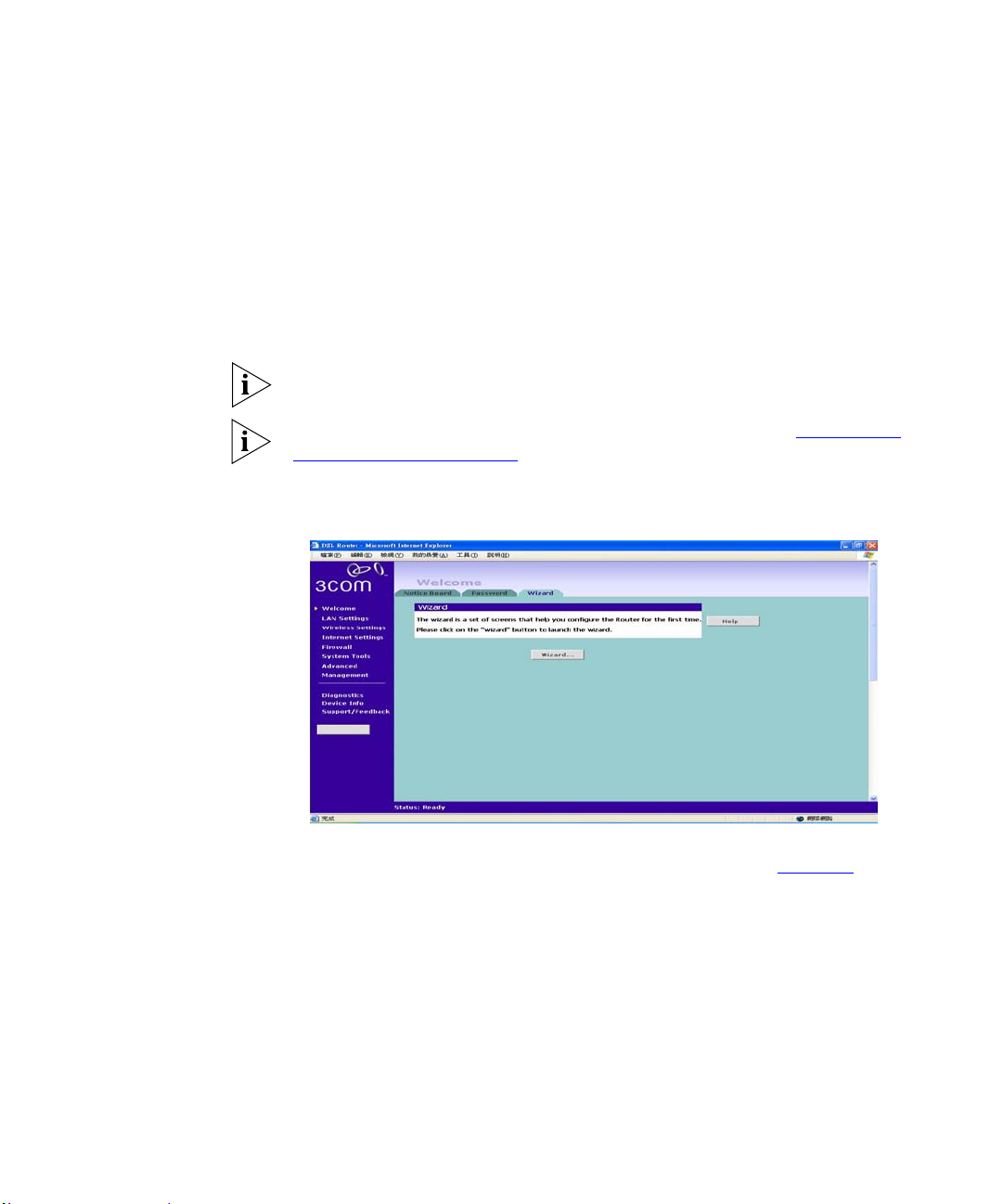
Wizard
If you have forg otten your passwor d y ou need to r eset the Ro uter. See "
Reset to
Factory Default" on page 69.
Figure 28 Wizard Screen
Click WIZARD... to launch the configuration wizard. Refer to Chapter 4 for
information on how to run the wizard.
Page 49
LAN Settings
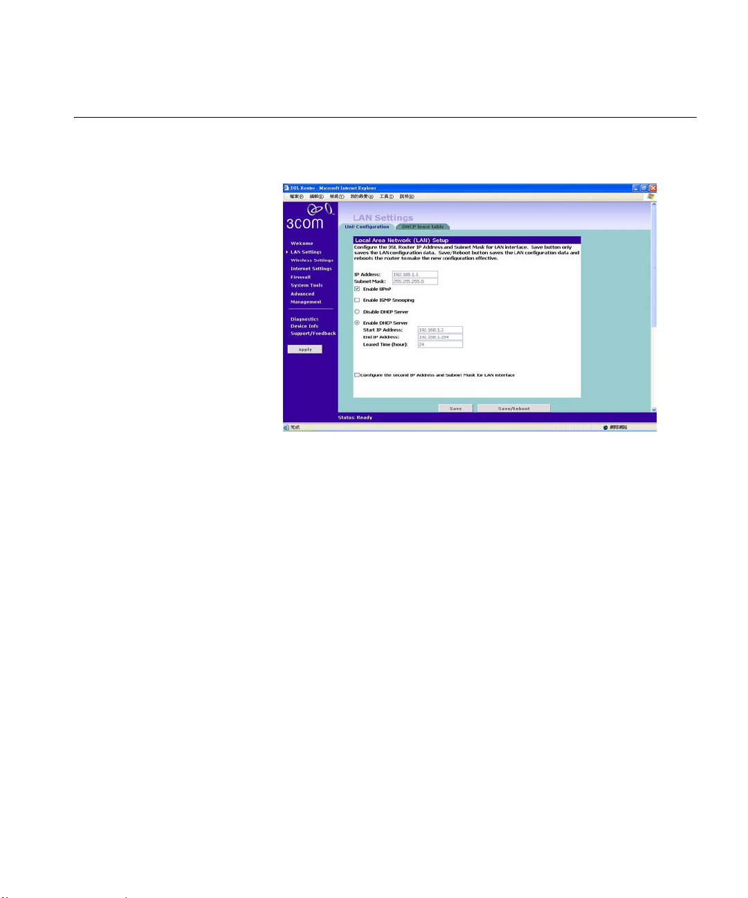
Unit Configuration Figure 29 LAN Setup Screen
LAN Settings 47
This screen allows you to change the IP address and subnet mask.
1 IP Address: Enter the IP Address for your LAN interface.
2 Subnet Mask: Enter the Subnet Mask for your LAN interface.
3 Enable IGMP Snooping:
4 Enable DHCP server on the LAN: Check this box to enable the DHCP service
on the router.
The Firewall Router contains a Dynamic Host Configuration (DHCP) server
that can automatically configure the TCP/IP settings of every computer on
your network.
5 Select Enable the DHCP server with the following settings: Enter the start
and end IP Address of your DHCP range. Enter the leased time in hours to
specify the frequency for DHCP assignment.
6 Configure the second IP Address and Subnet Mask for the LAN interface:
Check this box to make another set of IP Address and Subne t Mask to conn ect
to your router if they are not included in the range of DH CP server.
7 Enter the Secondary IP Address and Subnet Mask.
Page 50
48 CHAPTER 5: ROUTER CONFIGURATION
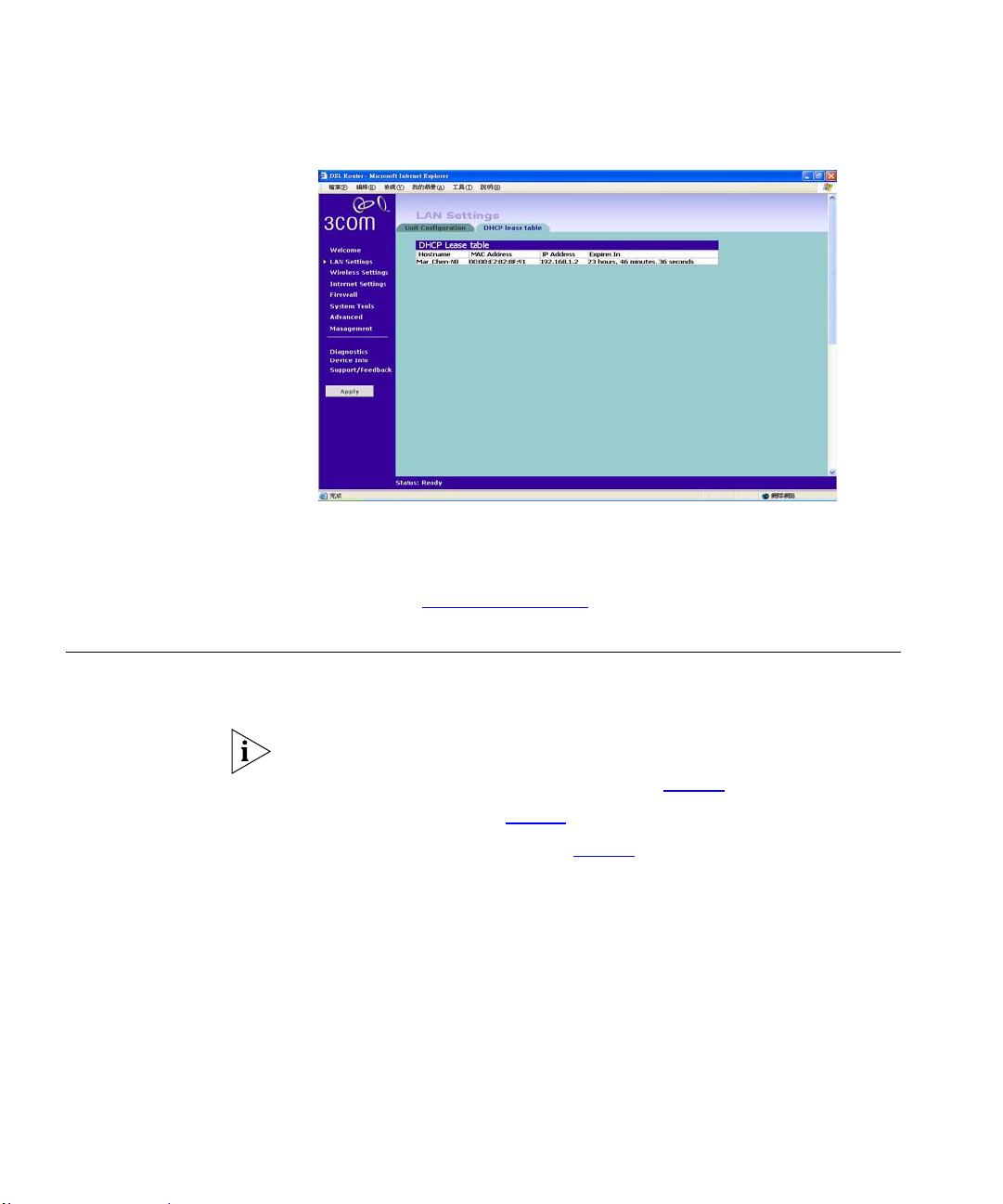
DHCP Lease Table Figure 30 DHCP Lease Table Screen
The DHCP Lease table screen list the client’s name, MAC Address, IP
Address and Expiration time which reflects the value specified in DHCP
server setting in “
Unit Configuration” on this chapter.
Wireless Settings The Wireless Settings menu provides options described in the following
sections.
To improve the security of your wireless netwo rk, 3Com recommends that you:
1. Change the SSID from its default value - see page 50
2. Enable Encryption - see page 51
3. Enable Connection Control - see page 57
Page 51
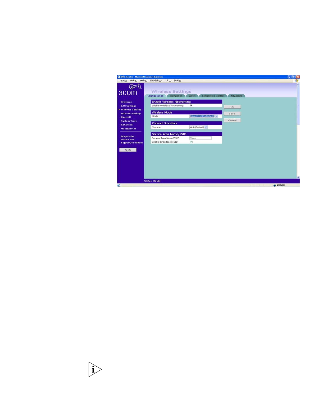
Configuration Figure 31 Enabling Wireless Screen
Enable Wireless Networking
Wireless Settings 49
Use this check box to enable or disable the wireless section of your LAN.
When disabled, no wireless PCs can gain access to either the Internet or other
PCs on your Wired or Wireless LAN through this Router.
Wireless Mode
Select a mode from the drop-down list to configure y ou r wireless networks.
The Router supports 11b, 11g, Super G, and Mixed 11b/11g which is the
default.
Channel Selection
Select a number from the drop-down list to specify which Channel the Router
will transmit and receive on. If another access point or Router nearby is using
the same Channel as you, there will be a reduction in the performance of your
network. If this seems to be the case, you should select a different channel
number. Usually the Wireless computers will scan to find the correct channel,
but if they don't you must configure them to use the same Channel number as
the Router.
Valid channels are country dependent. See “
Channels” on page 119 for a list
of channels approved by each country.
Page 52

50 CHAPTER 5: ROUTER CONFIGURATION
Service Area Name/SSID
This allows you to name your W ireless netwo rk. The Service Ar ea Nam e/SSID
field will accept any alphanumeric string and has a maximum length of 32
characters. Your Wireless computers must be configured with exactly the
same name or you will not establish a connection. The Service Area Name
may also be referred to as “ESSID” depending on your networking vendor. By
default the Router uses the name “3Com”. 3Com recommends that you
change the default name.
In order that your wireless computers can connect to the Router, you must:
Use Infrastructure Mode, not Ad hoc Mode.
Have the same Service Area Name as the Router.
Have the same Channel number as the Router.
Use the same encryption type and keys as the Router.
Ensure that the PC is included in the authorized Wireless PCs list if
Connection Control is enabled. See page 57
.
Enable Broadcast SSID
Disable this feature after you have installed your wireless network to improve
the security of your network. When the check box is checked, the Router will
broadcast the Service Area Name/SSID of your wireless network, which
reduces the security of your Router as it allows any wireless client to see your
wireless LAN.
If you have a wireless client that can detect all the available SSIDs in your
area, your client will not list the Router SSID unless this feature is enabled.
The clients will still be able to connect, provided that they are supplied with
the SSID.
3Com recommends that you install your wireless network with this feature
enabled and then disable it once you have set up the Router and wireless
clients.
After you have finished configuring yo ur Router, click on Save to save your
existing changes or Cancel to revert your changes.
Page 53
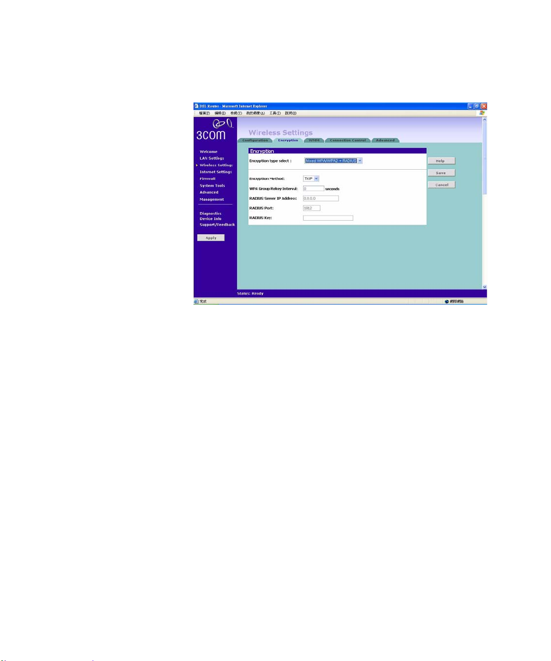
Encryption Figure 32 Encryption Screen
When setting up wireless networks, it is important to remember that with
encryption disabled, anyone with a Wireless PC can eavesdrop on your
network. 3Com recommends that you get the network working with
encryption disabled first and then enable it as the last step. This will simplify
setting up your network.
Wireless Settings 51
The Router supports two types of encryption:
WPA/WPA2/Mixed WPA WPA2 — Wi-Fi Protected Access (WPA) is a
subset of the IEEE 802.11i standard. Both WPA and WP A2 use Temporal Key
Integrity Protocol (TKIP), Message Integrity Check (MIC) and IEEE
802.11x. In addition to TKIP, WP A2 also uses Advanced Encryption Standard
(AES). The mixed mode will let you choose the encryption mechanism
interchangeably with either TKIP or AES.
WEP — Wireless Equivalent Privacy (WEP) is a 64 bit or 128 bit
encryption method with user configurable fixed k ey s .
Page 54

52 CHAPTER 5: ROUTER CONFIGURATION
WPA/WPA2/Mixed WPA WPA2 +Radius
PSK2+RADIUS features using of a RADIUS server with the pre-shared
key authentication method. (This should only be used when a RADIUS
server is connected to the Router).
WPA provides a higher level of security, provided by its longer key and
dynamic changes made to the key over time. 3Com recommends that you use
WPA with any clients which support it.
If you enable encryption on the Router, you must reconfigure your wireless
PCs to use exactly the same Encryption Type and Keys otherwise the devices
will not understand each other.
The encryption methods used by the Router secure data transmitted through
wireless communications between the Router and its wireless clients.
Enabling encryption has no security effect on data transmitted through wired
(Ethernet) connections or through your connections to the Internet.
Configuring
WPA/WPA2
Encryption
You can choose to use a RADIUS server to authenticate clients, or you can
specify a pre-shared key.
The pre-shared key is used to start the dialog between the Router and the
client. During this dialog, a new key is agreed, making it more di fficult to
eavesdrop on wireless networks encrypted using WPA, than those encrypted
using WEP.
To use a RADIUS Server to authenticate each user before they join the
network, refer to “
To set up the pre-shared key, refer to “Using Pre-Shared Passphrase”. on
page 54
.
Using the Radius Server”on page 53.
Page 55
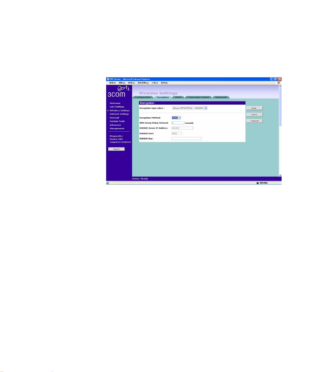
Using the Radius Server
Figure 33 WPA/WPA2 Encryption Screen - Radius Server
Wireless Settings 53
To set up WPA/WPA2/Mixed WPA and WPA2 with Radius Server:
1 Select Encryption Method from the dro p-down box.
2 Enter the frequency for key generating in seconds.
3 Enter the RADIUS Server IP address.
4 Enter the Server Port.
5 Enter the key for the Radius Server.
6 Click Save to save your changes.
Page 56
54 CHAPTER 5: ROUTER CONFIGURATION
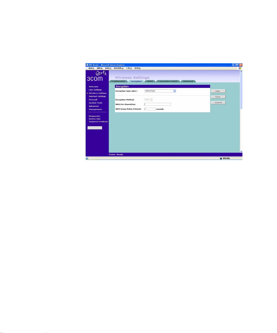
Using Pre-Shared Passphrase
Figure 34 WPA/WPA2 Encryption Screen - Pre-Shared Passphrase
Configuring WEP
Encryption
To set up Pre-Shared Passphrase as the WPA Type:
1 Select Encryption Method from the drop-down box. Enter a phrase of between
8 and 63 characters in length in the Pr e-Shared key field. This passphrase will
be used to generate a 256 bit key dynamically.
2 Enter the frequency for key generating in seconds
3 Click Save to save your changes.
There are two levels of WEP encryption available, 64 bit (sometimes referred
to as 40 bit) and 128 bit. Use the Encryption strength drop-down menu to
select the desired level.
Encryption Keys
Page 57
Wireless Settings 55
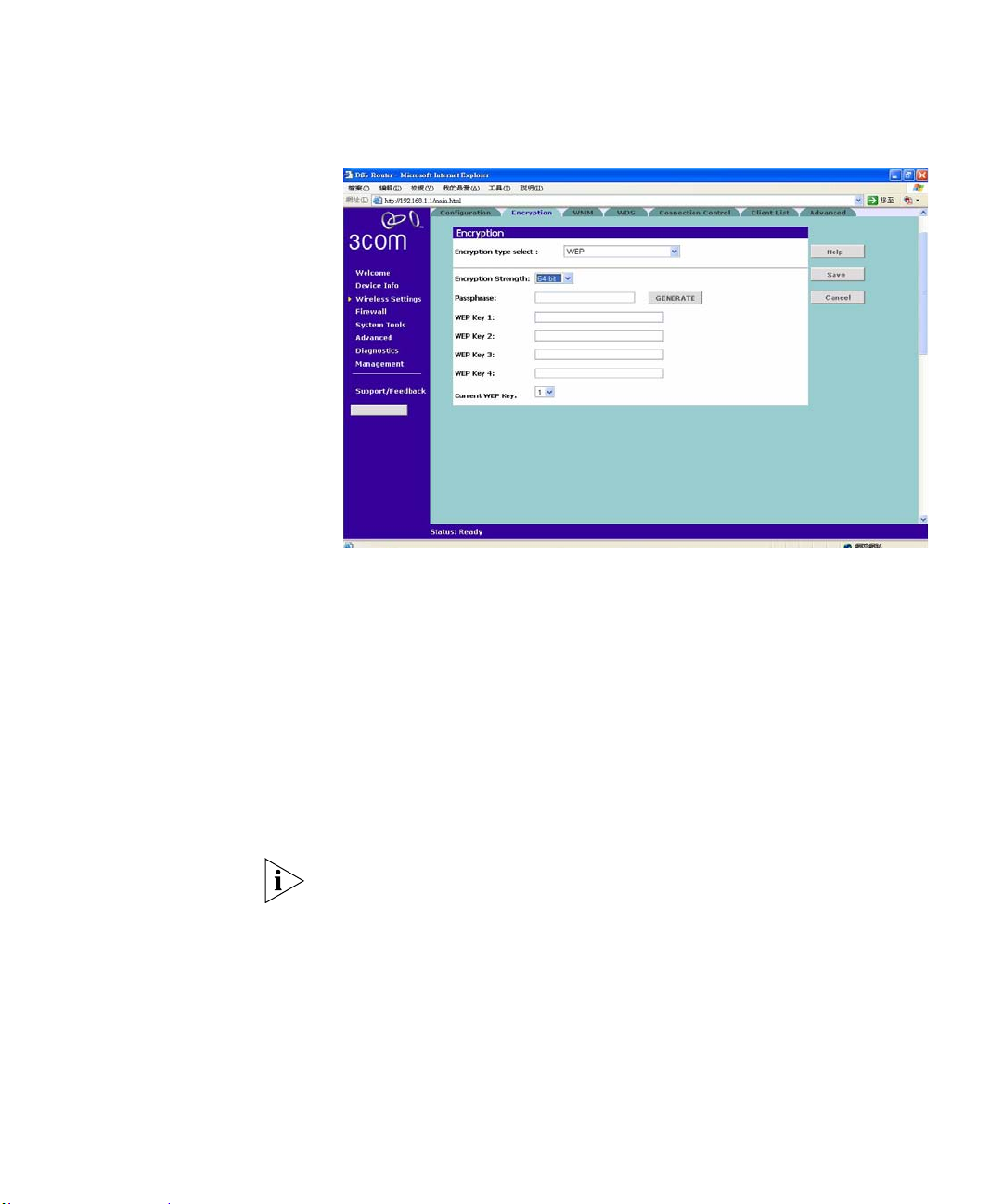
Figure 35 64 bit/128 bit Encryption Keys Screen - WEP Configuration
To set up WEP encryption:
1 Select 128 bit encryption or 64 bit encryption from the Encryption Strength
drop-down list.
2 Enter the passphrase which can be up to 31 characters long and may contain
any alphanumeric characters in the field.
3 Click on the Generate to generate 4 hex keys automatically. Virtually all
manufacturers support this scheme. Hexadecimal numbers are formed from
0-9 and A-F. In 64 bit WEP, the passphrase will generate 4 different keys.
However, in 128 bit WEP, this method only generates 1 key which is
replicated for all 4 keys.
If you encounter any difficulty when you enable WEP ensure that you check
that each key on your wireless computer is exactly the same as each key on
your Router. In other words, Key number 1 on the Wireless computer must
have the same Hex number as Key number 1 on the Router, Key 2 on the
Wireless computer must match Key 2 on the Router and so on.
4 Select the Current WEP Key, which is the key the Router uses when it
transmits. You can change the selected key periodically to increase the
security of your network.
5 Click on Save to save your changes.
Page 58
56 CHAPTER 5: ROUTER CONFIGURATION
Some wireless adapters have only one key available on their WEP
configuration page. If this is the case ensure it is the same as Key 1 on the
Router and that it is selected as the Current WEP key.
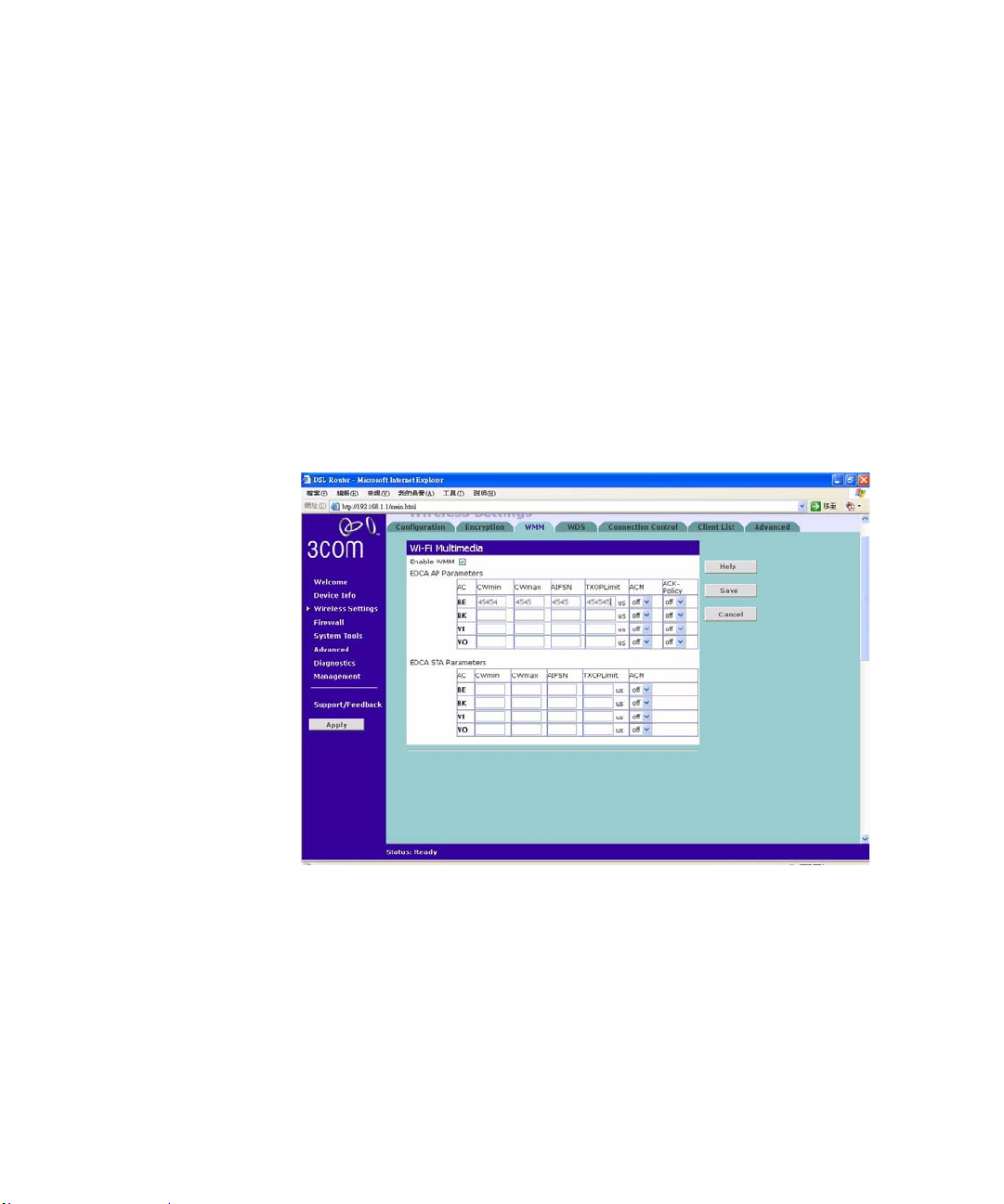
WMM Wi-Fi MultiMedia QOS (Quality of Service) ensures the quality of service in
wireless networks for multimedia applications. 3Com recommends that you
leave the settings unchanged if you are not sure with your configuration.
Changing the values may lead to unexpected blockages of traffic on your
wireless LAN, and the blockages might be difficult to diagnose.
WMM provides prioritized media access and is based on the Enhanced
Distributed Channel (EDCA) method.
Figure 36 WMM Screen
Admission Control- There are four types for Classes of Services:
BK: Background
BE: Best Effort
VI: Video
VO: Voice
Enter the appropriate values for each categories:
Page 59
CWmin: Minimum Contention Window. Enter a number from 0-10.
CWMax: Maximum Contention Wi ndow. Enter a number from 0-10.
AIFSN: Fixed Slot Time. Enter a number from 0-20.
TXOPLimit: Transmit Opportunity Limit. Enter a number from 0-65535
millisecond.
ACM/ACK-Policy: Admission Control Policy. Can be enabled or disabled.
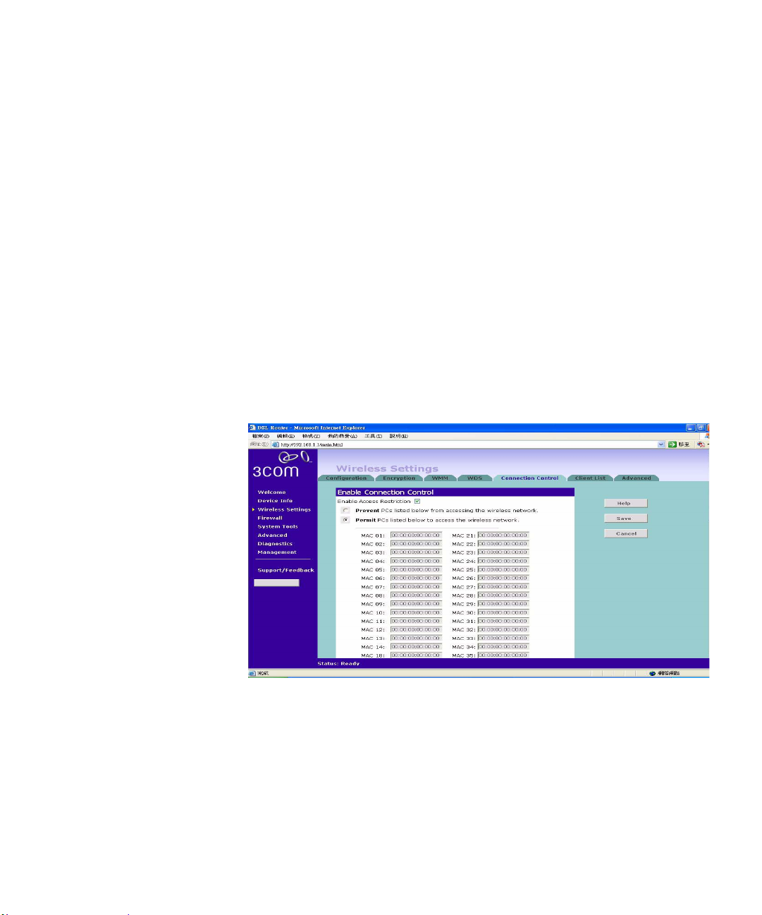
Connection Control Figure 37 Connection Control Screen
Wireless Settings 57
A higher level of security can be achieved for your wireless network if, in
addition to using encryption, you spe cify th at on ly certa in wi rele ss comp uters
can connect to the Router. By default, a ny wireless computer that has the same
Service Area Name/SSID, channel and encryption settings as the Router can
connect to it.
To specify that only certain wireless computers can connect to the Router,
select permit/prevent, and then enter the MAC address of the wireless clients.
If you enable this feature from a W ireless PC, it will automatically be added to
Page 60
58 CHAPTER 5: ROUTER CONFIGURATION
the Authorized Wireless PC list. You may enter a maximum of 40 PCs in the
list.
Click Save to save your existing configurations or Cancel to discard all
changes.
The MAC Address must be entered as 6 hexadecimal pairs, for example
12-34-56-78-ef-ab.
Advanced Wireless
Settings
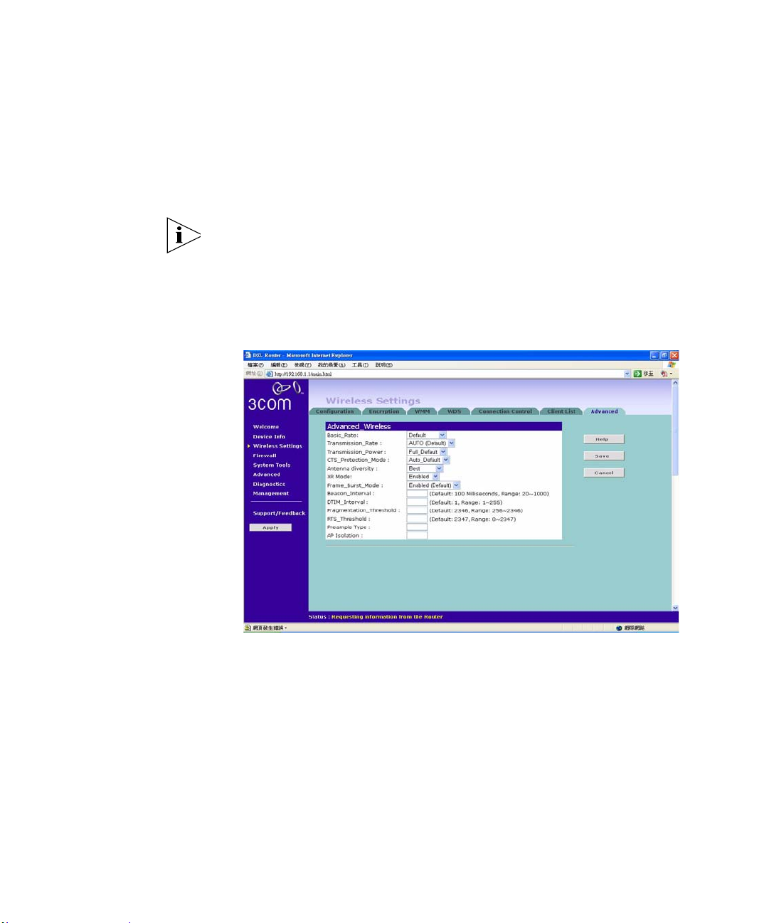
Figure 38 Advanced Wireless Screen
The Advanced Wireless Settings gives you more specific and advanced
options to configure your Wireless Router.
Beacon Interval: This value indicates the frequency interval of the beacon.
Abeacon is a packet broadcast by the Access Point to keep the network
synchronized. A beacon includes the wireless LAN service area, the AP
address, the Broadcast destination addresses, a time stamp, Delivery Tr affic
Indicator Maps, and the Traffic Indicator Message (TIM).
Page 61

Internet Settings 59
XR Mode: The router embeds the Atheros Super G technology
which stretches the performance of a WLAN by enabling long-range
connections. Select on the drop-down list to enable this feature.
RTS Threshold (Request To Send): Should you encounter inconsistent data
flow, only minor modifications are recommended.
The threshold (number of bytes) for enabling RTS/CTS handshake. Data with
its frame size larger than this value will perform the RTS/CTS handshake.
Setting this attribute to be lar ger th an the max imum MSDU(MAC service data
unit) size turns off the RTS/CTS handshake. Setting this attribute to zero turns
on the RTS/CTS handshake. Enter a value between 0 and 2432.)
Fragment Threshold defines a threshold above which the wireless packet
will be split up, or fragmented. For a fragmented packet, if transmission of
part of it were to be interfered with, only the portion that was successfully
transmitted would need to be re-sent. Throughput will generally be lower for
fragmented packets, since the fixed packet overhead consumes a higher
portion of the RF bandwidth.
DTIM Interval: This value indicates the interval of the Delivery Traffic
Indication Message (DTIM). A DTIM field is a countdown field informing
clients of the next window for listening to broadcast and multicast messages.
When the Access Point has buffered broadcast or multicast messages for
associated clients, it sends the next DTIM with a DTIM Interval value. Acc ess
Point Clients hear the beacons and awaken to receive the broadcast and
multicast messages.
Internet Settings The Internet Settings let you view your current WAN configuration and
modify it. You may also add/delete new configuration.
Add a new WAN configur ation: please refer to Chapter 4
Wizard”
on “Accessing the
Firewall On the main frame of the Firewall setup screen is a menu with six tabs:
Virtual Servers, Special Applications, DMZ, SPI, Internet Access Policy and
Content Filter.
Page 62
60 CHAPTER 5: ROUTER CONFIGURATION
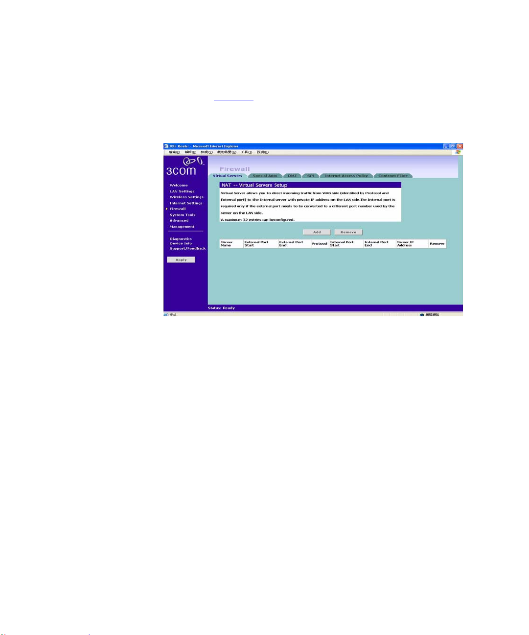
Virtual Servers Selecting the Firewall option on the main menu displays the Virtual Servers
setup screen. (Figure 39
Figure 39 Virtual Servers Screen
)
Activating and configuring a virtual server allows one or more of the
computers on your network to function as a public server. For example, one of
your computers could be configured as an FTP server , allowing others outside
of your office network to download files of your choosing. Or, if you have
created a Web site, you can configure one of your computers as a W eb server,
so that others can view your Web site.
To configure a virtual server:
1 Click Add open the Virtual Server Settings page.
2 Select a service from the drop-down list or type in your desired services.
3 The commonly used port with the associated service will be entered in the
table automatically. You may change them manually.
4 Click Save/Apply to save the settings.And the confirmed entries will be
displayed.
5 Click Add to return to the Virtual Server configuration page to enter more
entries.
The are a total of 32 services can be defined in the Virtual Server.
Page 63
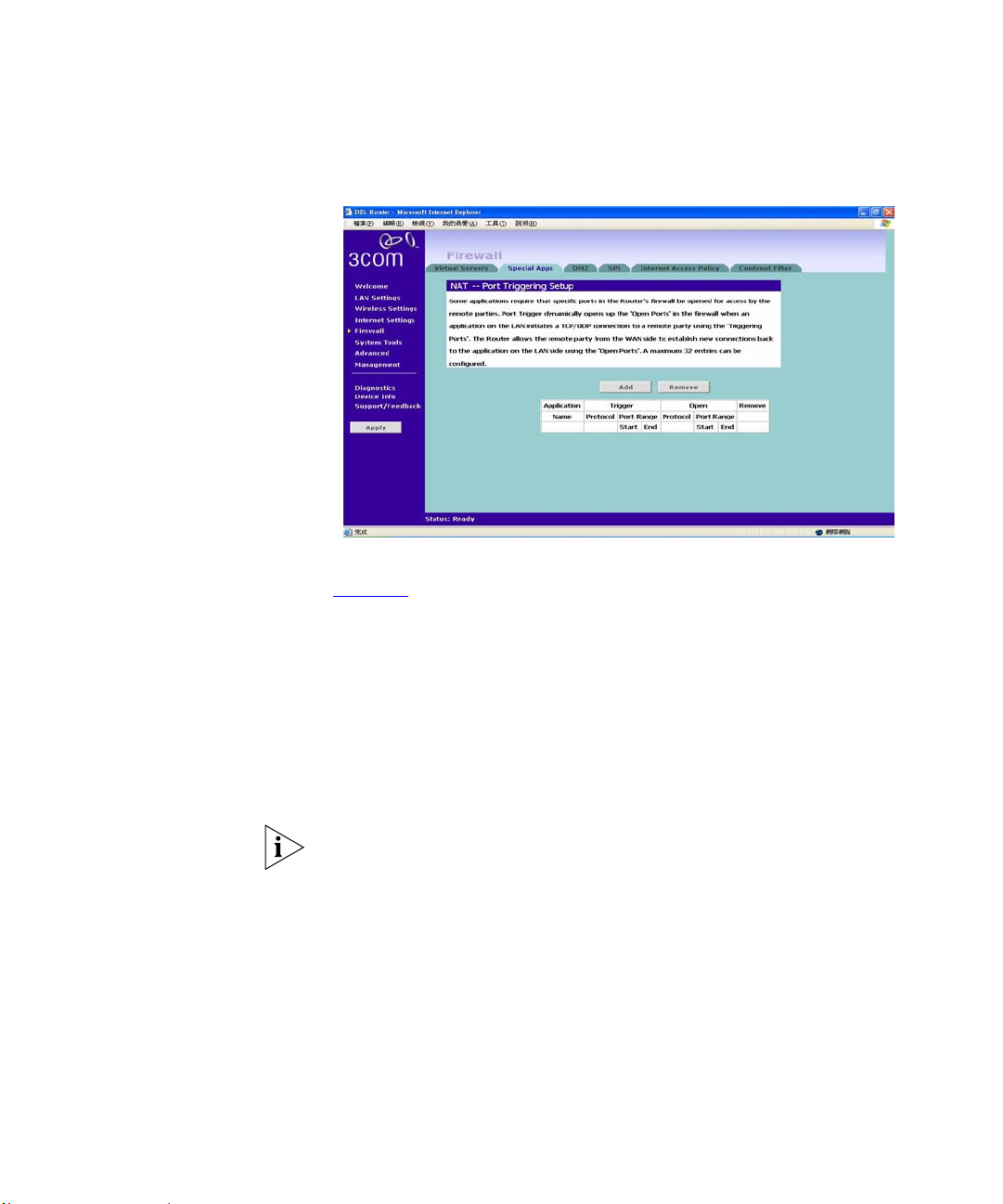
Special Applications Figure 40 Special Applications Screen
Select Special Apps tab to display NAT-Port Triggering Setup screen.
(Figure 40
)
Firewall 61
Some software applications require special or multiple connections to the
Internet and these would normally be blocked by the firewall. For example
Internet Telephony or Video conferences require multiple connections.
So that these special applications can work properly and are not blocked, the
firewall needs to be told about them. In each instance there will be a trigger
port and incoming port(s), where traffic on the trigger port tells the firewall to
open the incoming ports.
Each defined Special Application only supports a single computer user, and
up to 32 Special Applications can be defined. Any incoming ports opened by a
Special Application trigger will be closed after five minutes of inactivity.
To configure special applications:
1 Click Add open the Virtual Server Settings page.
2 Select a service from the drop-down list or type in your desired services.
3 The commonly used port with the associated service will be entered in the
table automatically. You may change them manually.
4 Click Save/Apply to save the settings. And the confirmed entries will be
displayed.
Page 64
62 CHAPTER 5: ROUTER CONFIGURATION
5 Click Add to return to the Special Application configuration page to enter
more entries.
The Router will automatically allow FTP and NetMe eting sessions. You do not
need to configure these as Special Applications.
Only one computer on your network can use the special application at any one
time.
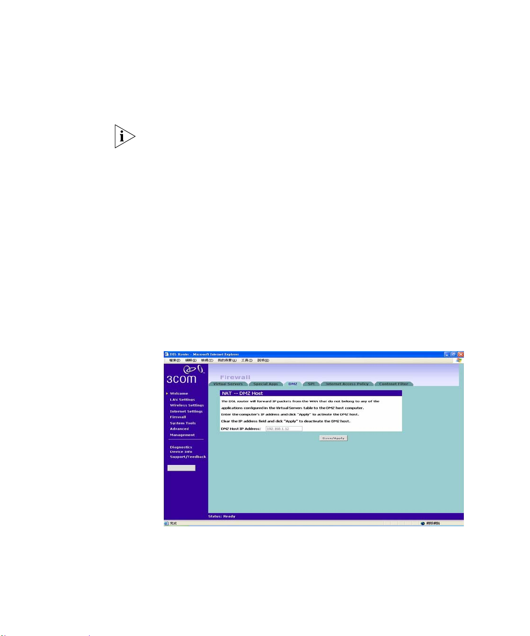
Virtual DMZ DMZ (De-Militarized Zone) Host is a computer without the protection of the
firewall. This feature allows a single computer to be exposed to unrestricted
2-way communication from outside of your network. This feature should be
used only if the Virtual Server or Special Applications options do no t prov ide
the level of access needed for certain applications.
T o configure one of your computers as a DMZ host, enter the IP address of the
computer in the DMZ Host IP Address, and then click Save/Apply.
Figure 41 Virtual DMZ Screen
Page 65
Firewall 63
SPI Stateful Packet Inspection (SPI) inspects, and if required blocks packets at the
application layer. SPI also maintains TCP and UDP session information,
including timeouts and the number of acti ve sessi ons, a nd pro vide s the abili ty
to detect and prevent certain types of network attacks such as DoS attacks.
Denial of Service (DoS) attacks are aimed at devices and networks with a
connection to the Internet. The goal is not to steal information, but to disable
a device or network so users no longer have access to network resources.
To configure SPI information on your Router:
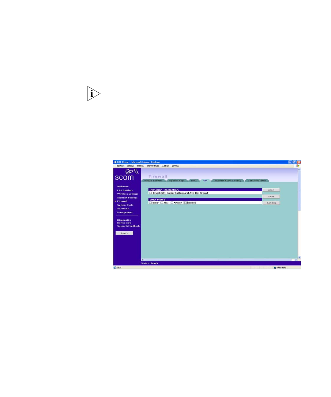
1 Select Firewall from the main menu, then select the SPI tab to display the SPI
screen (Figure 42
Figure 42 SPI Screen
):
Intrusion Detection: Check on the box to enable the Stateful Packet
Inspection (SPI), Hacker Pattern detection and Denial of Services (DOS)
features to further guard your networks from internet attacks.
Web Filters: Check on the box to filter out the internet activities/programs
from the following: Proxy, Java, ActiveX, and Cookies.
Click on Save to save your changes or Cancel to cancel your changes.
Page 66
64 CHAPTER 5: ROUTER CONFIGURATION
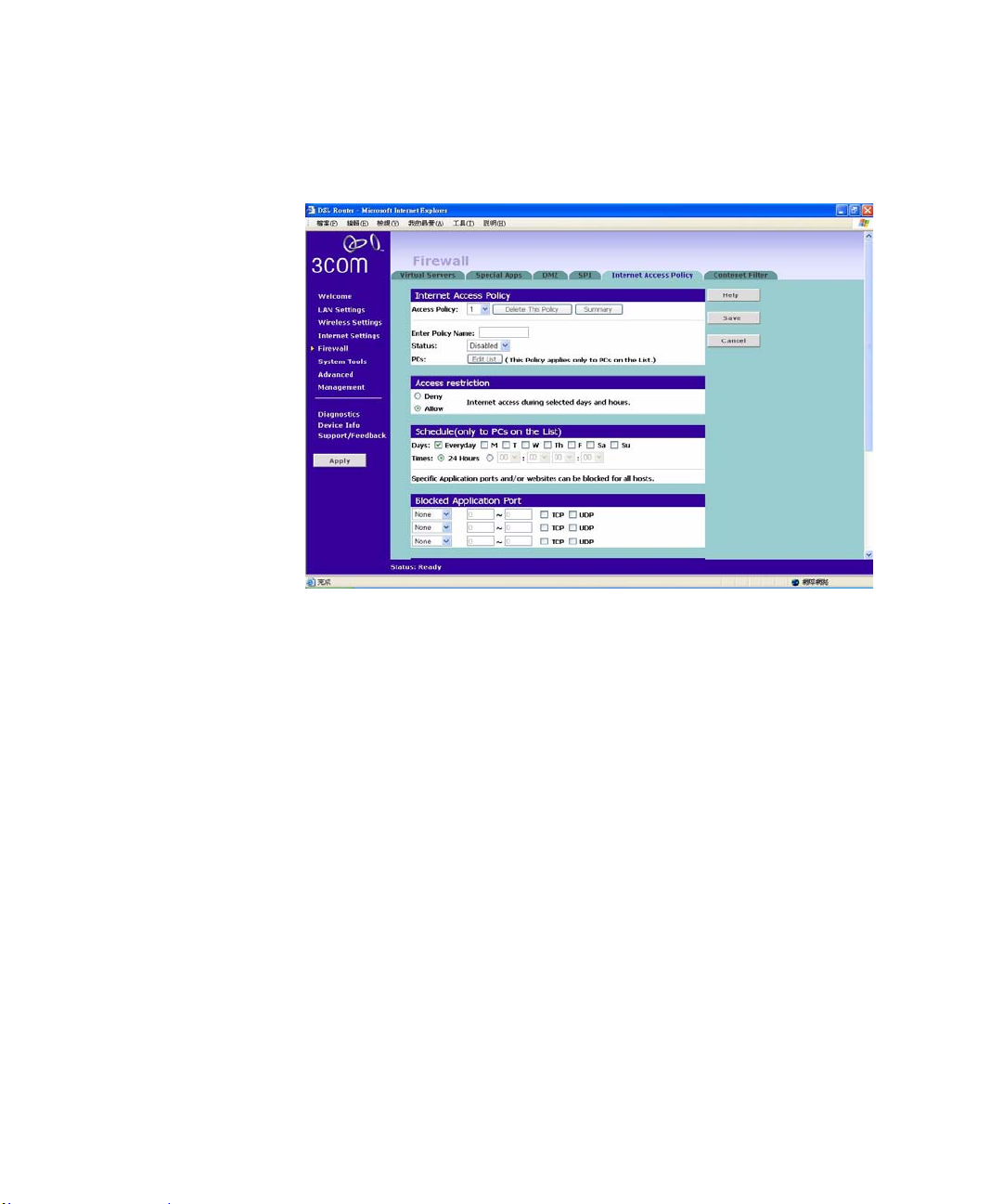
Internet Access Policy Figure 43 The Internet Access Policy Screen
The Internet Access Policy screen lets you configure your Router’s access availability according to specified day/time with options in blocking the application, website (URL), and website keywords.
1 Select Access Policy number from the drop-down menu.
2 Enter the Policy Name in the field provided.
3 Select on Status for enabling or disabling this policy.
4 The policy can be applied to a single client or a group clients.
T o do this, enter the MAC Addresses or the IP Addresses of each PC up to the
total number limited by the number of the entries.Or enter the range o f PC’ s IP
Address with the last digits of their IP Addresses.
5 Select on Deny/Allow to specify your restriction types.
6 To change the schedule, check the appropriate check box for each day you
want to allow access, and enter the permitted access times for each day in
24-hour clock format.
Page 67

Firewall 65
For example, to allow access Monday through Friday between 9 am and 5 pm,
check the check boxes for Mon, Tue, Wed, Thu and Fri, and enter 09:00 and
17:00 in the text boxes next to each of these days.
7 Select on an internet service/application to blocked the service/port number.
8 Type in the Website Accessing by URL Address with the URL that you want
to block access from.
9 Type in the Website Blocking by Keyword with the keywords on the URL.
10 Click Save to save the settings or Cancel to discard them.
To assign different access rights for different computers:
1 Click on the drop-down menu for a different number of the policy. And follow
the previous steps for the rest of configuration. You can create up to 10
policies.
URL Filter: To filter a specific site, enter the URL for that site. For example,
to stop your users from browsing a site called www.badsite.com, enter
www.badsite.com or badsite.com in one of the fields.
If badsite.com has multiple sub-domains, such as this.badsite.com and
that.badsite.com then you can either:
Block them individually by entering this.badsite.com in one field
and that.badsite.com in another.
or
Block them by entering the keyword badsite.com into one of the
fields. This will block all URLs containing the string badsite.com. As well as
blocking this.badsite.com and that.badsite.com, the keyword
badsite.com would block searches that mentioned badsite.com in their domain
name, for example www.notabadsite.com.
To filter a generic keyword enter it into one of the fields. You should exercise
caution when choosing a keyword as many keywords are contained within
other words. For example, filtering the word sex would filter the following
example URLs:
www.sussex.com
www.thisexample.com
Page 68
66 CHAPTER 5: ROUTER CONFIGURATION
You can filter up to 4 keywords and URLs.
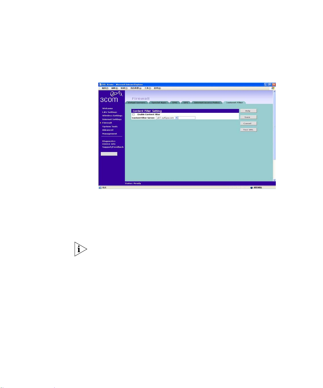
Content Filter Figure 44 The Content Filter Screen
The content filter lets your block the websites according to pre-define d
categories.
You can subscribe to the 3Com Content Filter Service, which enables you to
block or allow the URLs of a number of pre-defined categories.
The Router comes with a 14-day free trial of the 3Com Content Filter Se rvice.
To activate the 14-day free trial of the service, you must first register your
Router at
www.3com.com. To continue using the service after the trial period,
you must purchase the full 3Com Content Filter Service (3CSBCFS).
URL filtering rules supersede content filtering rules. If the 3Com Content
Filter is blocking certain Web sites that you want to allow, you can add these
sites to URL Filter’s allow list
To activate Content Filtering:
1 Select Firewall from the main menu, then select the Content Filter tab.
Content Filter Screen
2 Check the Enable Content Filter check box.
3 Select the Content Filter Server that you require from the drop-down list. If
you select custom entry, enter the server IP address in the text box.
Page 69
System Tools 67
4 Select the Server Timeout value in milliseconds. The default is 3000
milliseconds (3 seconds).
5 Select Allow or Deny for each displayed category, as required.
Click Save to save the settings, Te st URL to test the connection with th e
specified content filter server or cancel to discard your changes.
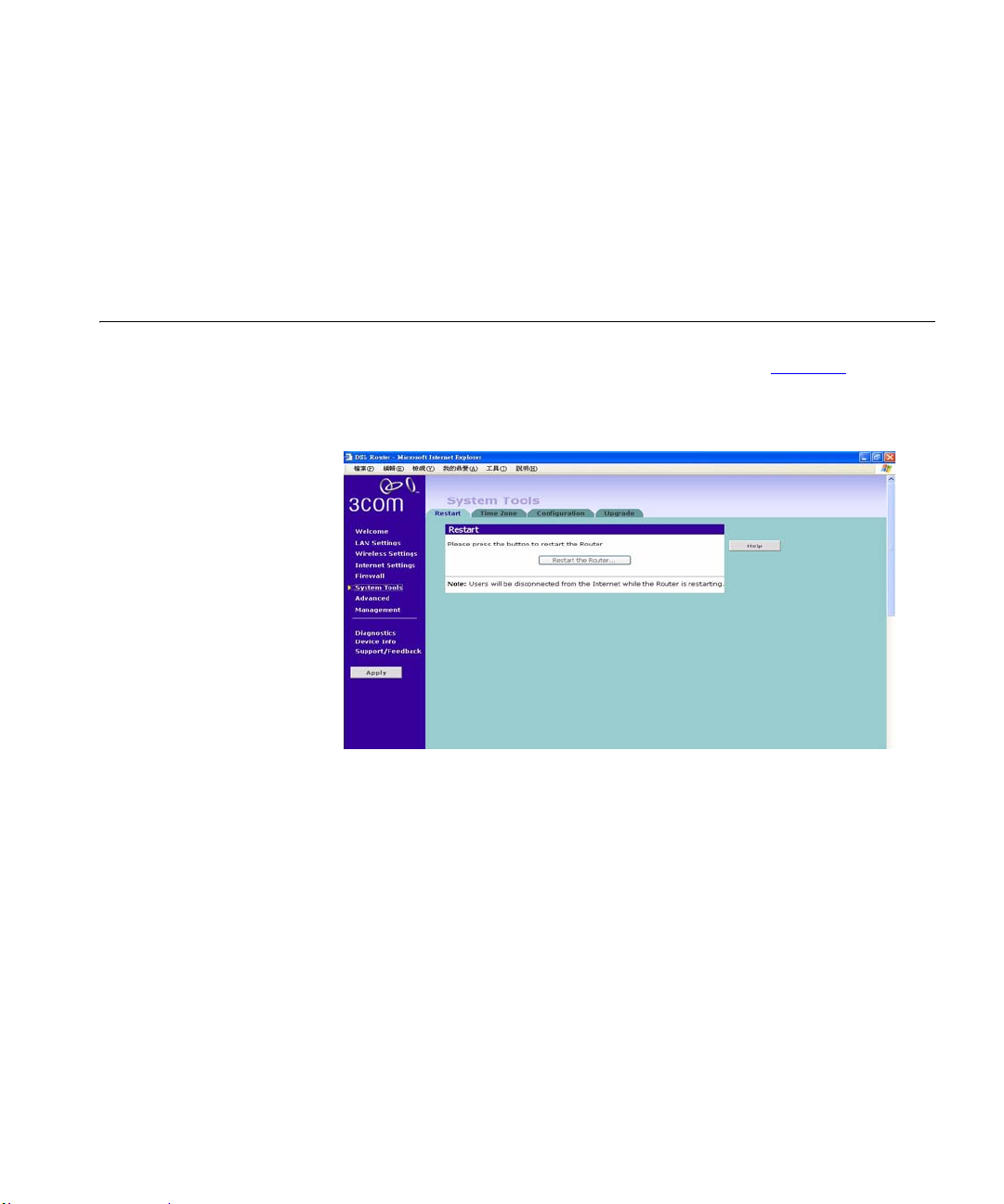
System Tools The main frame of the System Tools screen includes four administration
items: Restart, Time Zone, Configuration, and Upgrade (Figure 45
).
Restart
Figure 45 Restart Screen
If your Router is not operating correctly, you can choose to restart the Router
by selecting Restart the Router, simulating the effect of power cycling the
unit. No configuration information will be lost but the log files will be erased.
This function may be of use if you are experiencing problems and you wish to
re-establish your Internet connection. Any network users who are currently
accessing the Internet will have their access interrupted whilst the restart takes
place, and they may need to reboot their computers when the restart has
completed and the Router is operational again.
Page 70
68 CHAPTER 5: ROUTER CONFIGURATION
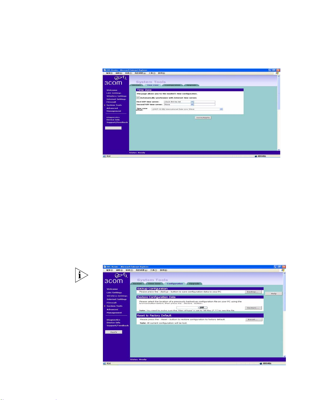
Time Zone Figure 46 Time Zone Screen
Check the Automatically synchronize with internet time servers to read the
correct time from NTP servers on the Internet and sets its system clock
automatically. You may enter two NTP servers according to your priority.
Choose the time zone that is closest to your actual location. The time zone
setting is used by the system clock wh en displ aying th e correct t ime in th e log
files.
Configuration
Click on Save/Apply to apply your settings.
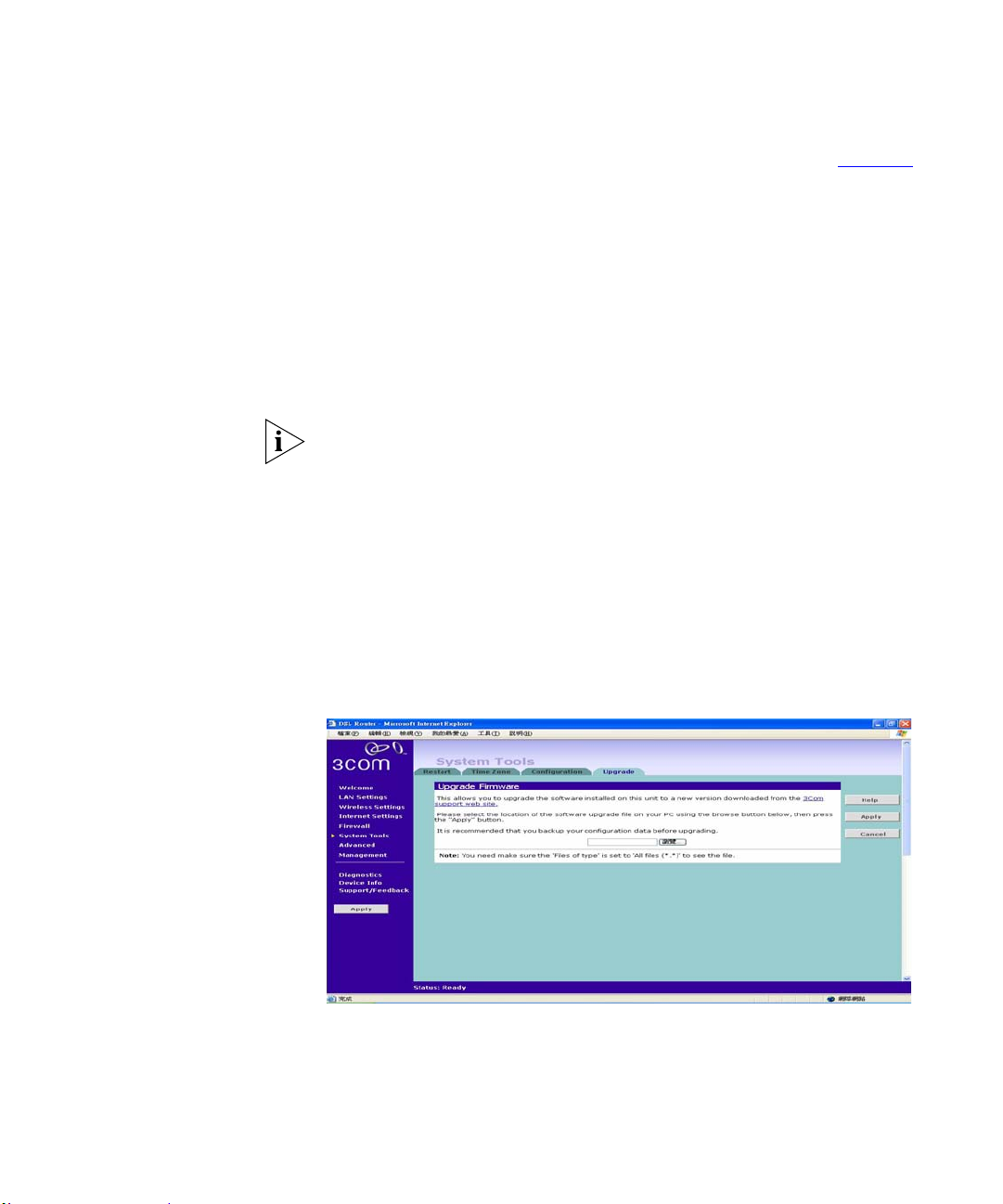
Figure 47 Configuration Screen
Page 71
System Tools 69
Select the Configuration tab to display the Configuration screen (Figure 47).
Backup Configuration
Click BACKUP to save the current Router configuration. You will be
prompted to download and save a file to disk.
Restore Configuration Data
If you want to reinstate the configuration settings previously saved to a file,
press Browse to locate the backup file on your comp ute r, and then click
RESTORE to copy the data into the Router's memory.
The password will remain unchanged.
Reset to Factory Default
If you want to reset the settings on your Ro uter to those that were l oaded at the
factory, click RESET. You will lose all your configuration changes. The
Router LAN IP address will revert to 192.168.1.1 and so are the wireless
settings, and the DHCP server on the LAN will be enabled. You may need to
reconfigure and restart your computer to re-establish c ommun ic ati on with the
Router.
Upgrade
Figure 48 Upgrade Screen
The Upgrade facility allows you to install on the Router any new releases of
system software that 3Com may make available. To in stall new software, you
first need to download the software from the 3Com support web site to a
folder on your computer. Once you have done this, select Browse to tell your
Page 72
70 CHAPTER 5: ROUTER CONFIGURATION
web browser where this file is on your computer, and then click Apply. The
file will be copied to the Router, and once this has completed, the Router will
restart. Although the upgrade process has been designed to preserve yo ur
configuration settings, it is recommended that you make a backup of the
configuration beforehand, in case the upgrade process fails for any reason (for
example, the connection between the computer and the Router is lost while
the new software is being copied to the Router).
The upgrade procedure can take up to two minutes, and is complete when the
Alert LED has stopped flashing and is perman ently of f. Make sure th at you do
not interrupt power to the Router during the upgrade procedure; if you do, the
software may be corrupted and the Router may not start up properly
afterwards. If the Alert LED comes on continuously after a failed upgrade,
refer to Chapter 6
,“Troubleshooting”.
Advanced Selecting Advanced from the main menu displays the following five tabs in
your Web browser window: Routing, Static Route, RIP, DDNS, DSL, IPSec,
Proxy ARP and ALG.
Routing The Routing-Default Gateway screen
Check the box Enable Automatic Assigned Default Gateway to automatically
assign a gateway to the router. Or you may enter the Default Gateway IP
Address in the field provided and select on its associated interface.
Page 73
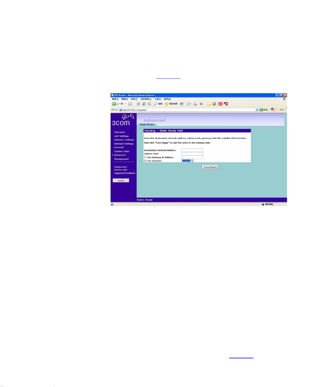
Advanced 71
Static Route Router supports static route functionality. Select the Static Route tab to display
the screen shown in Figure 49
Figure 49 Static Route screen
Please enter the following values in the box respectively to specify a static
route:
Network Address - the network address of the route. If network address
and subnet mask are both set to 0.0.0.0, this is the default route.
Subnet Mask - the subnet mask of the route. If network address and subnet
mask are both set to 0.0.0.0, this is the default route.
Gateway - the gateway used to route data to the network specified by the
network address.
The network interface associated with the IP address.
RIP The Router supports the Routing Information Protocol (RIP). RIP allows you
to set up routing information on one RIP enabled device, and hav e that routing
information replicated to all RIP enabled devices on the network. LAN and
WAN interfaces can be configured independently of each other.
Select the RIP tab to display the screen shown in Figure 50
Page 74
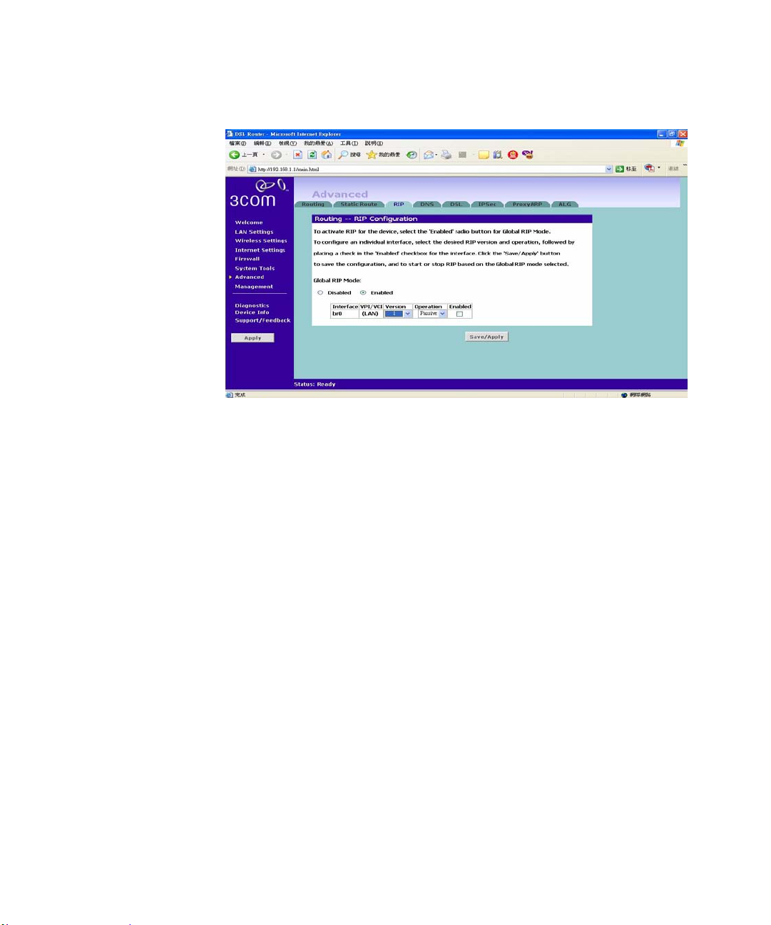
72 CHAPTER 5: ROUTER CONFIGURATION
Figure 50 RIP screen
Setting Up RIP
Check the Enable Global RIP Mode check box check box to configure RIP on
the Router.The screen displays RIP information for the LAN interface and
WAN interface. To set up or change the informatio n for on e or both interfaces:
1 Select one of Disable, Enable or Silent from the Operation Mode drop-down
list. If you select Enable, the Router transmits RIP update information to other
RIP enabled devices. If you select Silent, the Router only receives RIP update
messages.
2 Select either 1 (for RIPv1) or 2 (for RIPv2) from the Version drop-down list.
3Com recommends that you use RIPv1 if there is any RIP enabled device on
your network that does not support RIPv2. In all other cases, select RIPv2.
3 Select either Enable or Disable from the Poison Reverse drop-down list.
Poison Reverse is a feature that helps prevent data loops.
Page 75
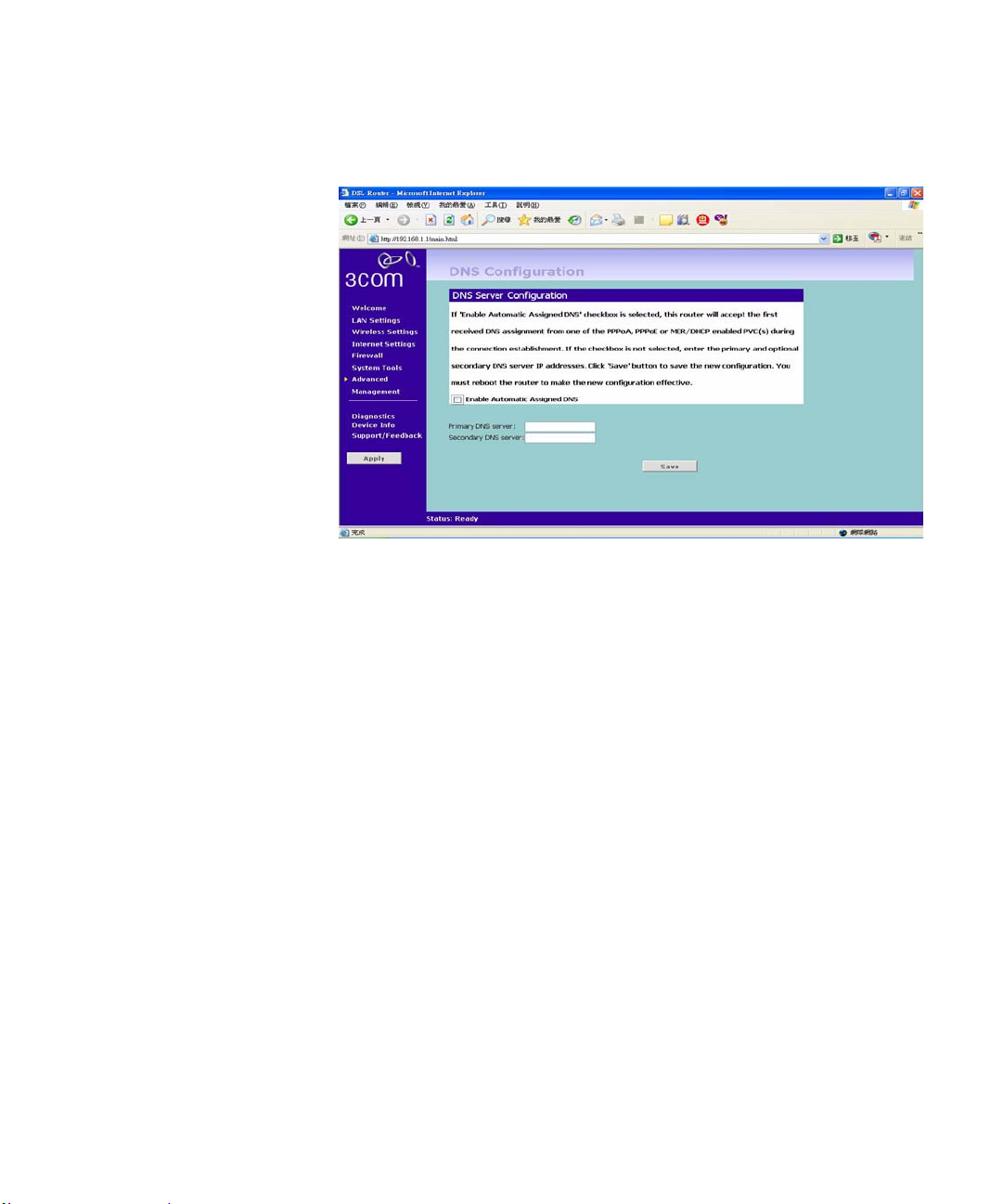
DNS The DNS Screen
The DNS Screen lets you specify your Domain Na me Serv ice (D NS) serve r’ s
information. You may check the Enable Automatic Assigned DNS for
automatically assigned DNS or you may manually specify your DNS server’s
IP Address.
Advanced 73
DDNS Dynamic Domain Name Server (DDNS) enables you to map a static domain
name to a dynamic IP address. The Router supports two DDNS providers,
TZO.com and DYNDNS.org. Before you can set up DDNS, you must obtain
an account, password and static domain name from your DDNS provider.
DDNS is disabled by default.
Page 76
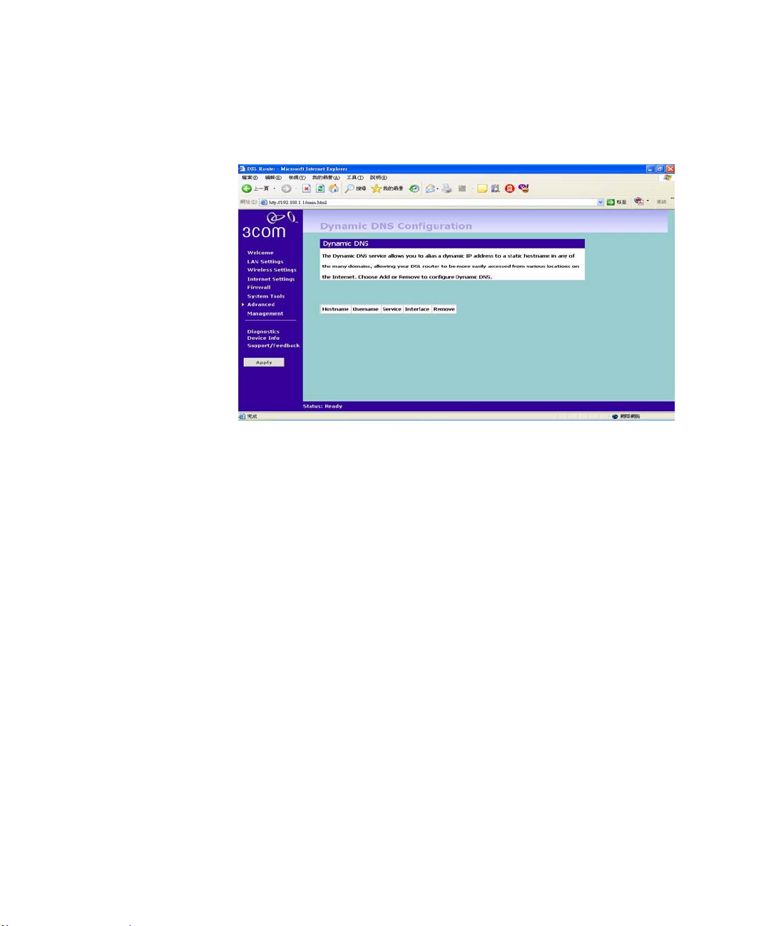
74 CHAPTER 5: ROUTER CONFIGURATION
To set up DDNS:
Figure 51 DDNS screen
4 Select a DDNS Service provider from the drop-down list. This can be either
TZO.com or DynDNS.org.
TZO.com
If you select TZO.com:
1 In the Host Name text box, enter the host name.
2 In the Interface text box, select the WAN/LAN interface that will be using the
DDNS.
3 In the Username/E-mail text box, enter the account name.
4 In the Key text box, enter the account password.
5 Click Apply to make this service active.
DynDNS.org
If you select DYNDNS.org:
1 In the Host Name text box, enter the host name.
2 In the Username text box, enter the account name.
3 In the Password text box, enter the account password.
4 In the Refresh T ime box, enter ho w often you want the serv ice to automatically
refresh, in days. The default is three days.
5 Click Apply to make this service active.
Page 77
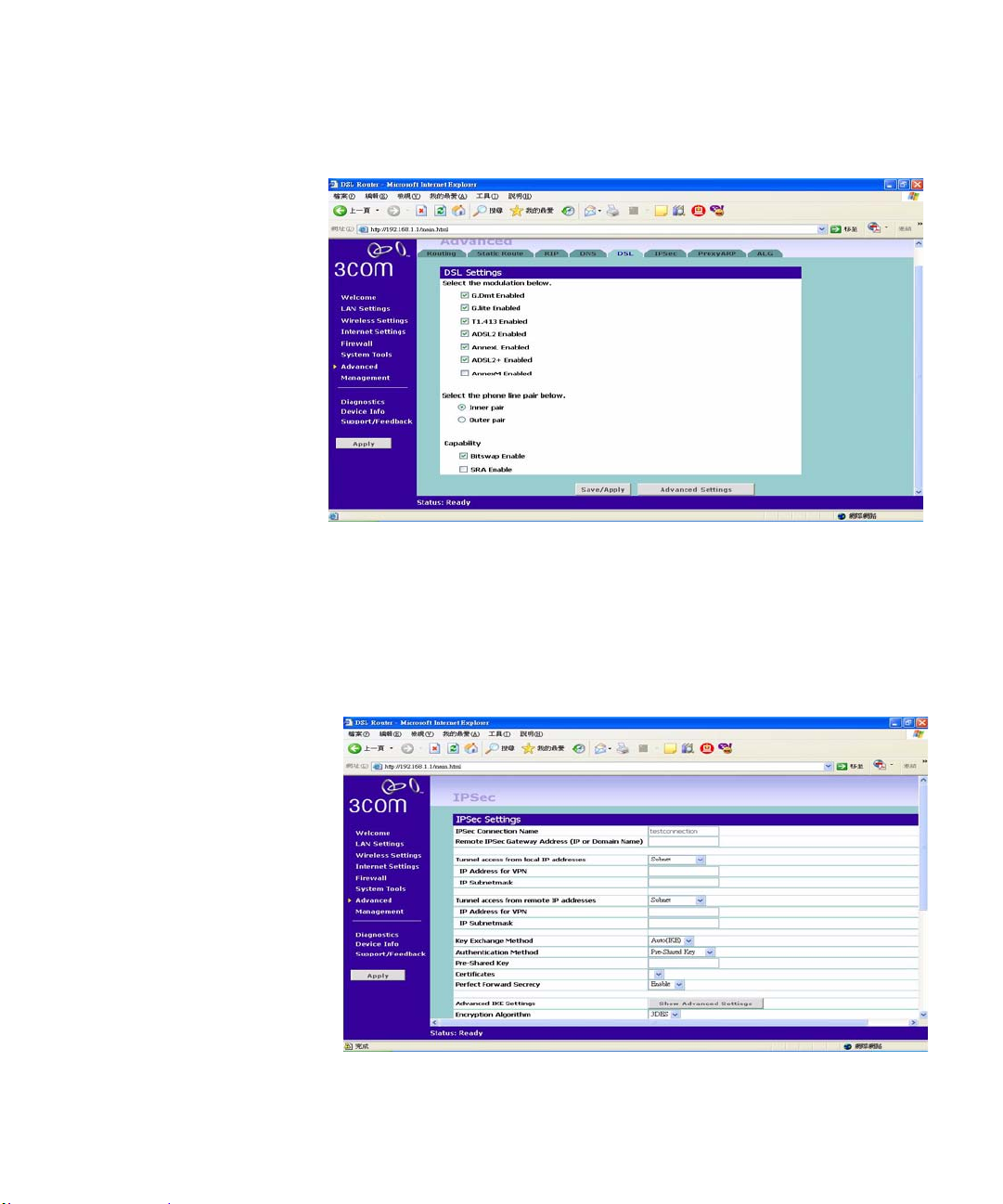
DSL Figure 52 The DSL Setting Screen
The DSL Screen lets you configure your DSL connections. Check the boxed
for the type of DSL connection that you are using. Select the type of phone
line you are using. Also Check the compatibility type.
Advanced 75
IPSec
Figure 53 IPSec Screen
Internet Protocol Security (IPSec) is a standards-based VPN that offers
flexible solutions for secure data communication s across a public network like
Page 78
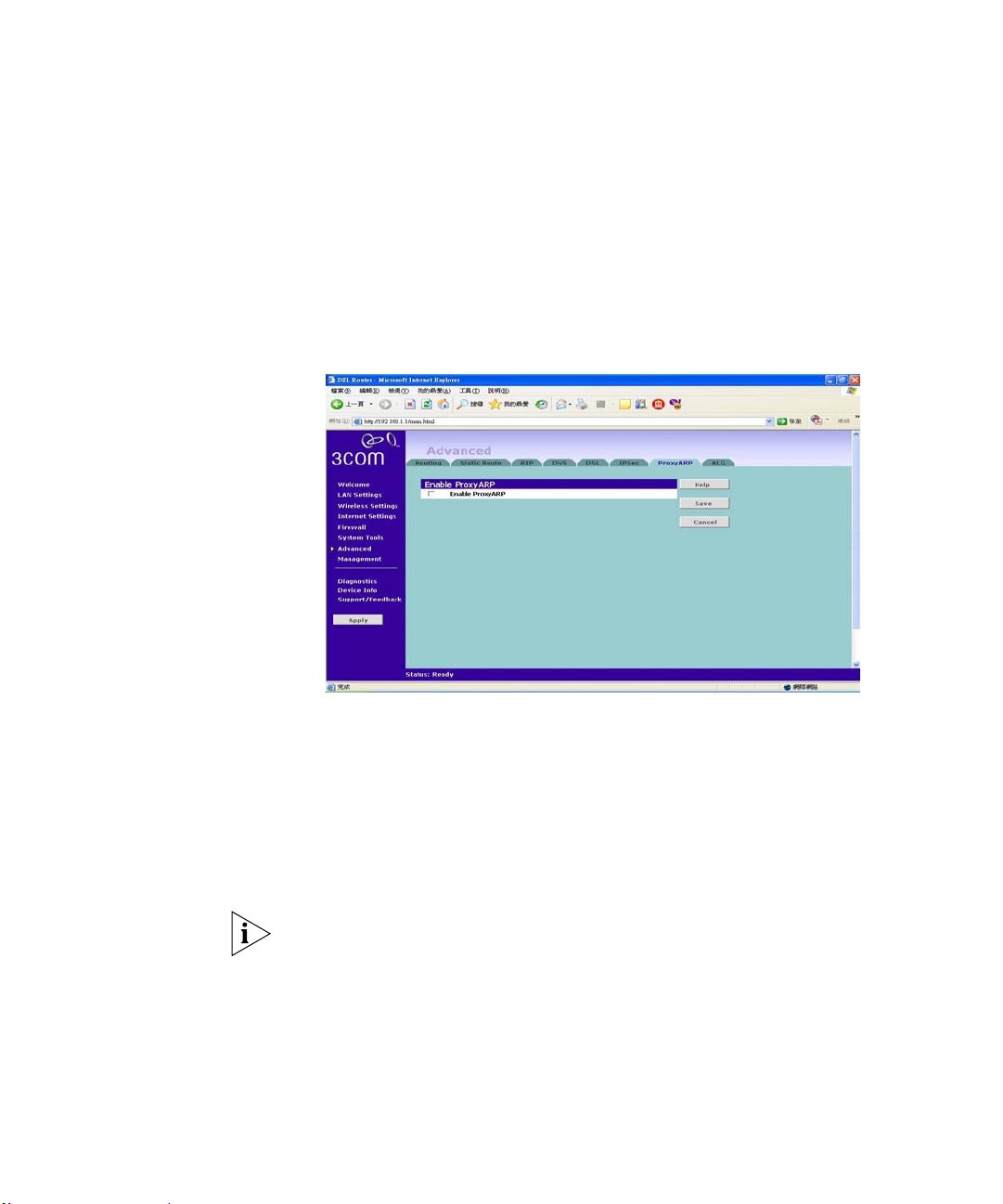
76 CHAPTER 5: ROUTER CONFIGURATION
the Internet. The Virtual Private Network (VPN) is a popular technolo gy u sed
for communications between two networking sites without the expense of
leased site-to-site lines.
Click on Add New IPsec to add new IPSec configurations. Select on the dropdown menu and enter the values in the text boxes for settings in your IPSec.
Proxy ARP
Figure 54 The Proxy ARP Screen
Proxy ARP is a variation of Address Resolution Protocol (ARP), in which an
intermediate device (in this case, the Router) sends an ARP response on
behalf of an end node to the requesting host. Proxy ARP can help decrease
bandwidth consumption on slow-speed WAN links and allows a site to use a
single IP address for two physical networks.
To use proxy ARP, you must have a range of static IP addresses assigned by
your ISP. Before configuring proxy ARP on the router, you must
Proxy ARP only works when the Router is assigned a static IP address.
To configure Proxy ARP:
1 On the menu, click Advanced.
2 Click the Proxy ARP tab.
3 Select the Enable Proxy ARP check box.
4 In IP Range From, type the starting IP address of the IP address range that
your ISP assigned to you.
Page 79
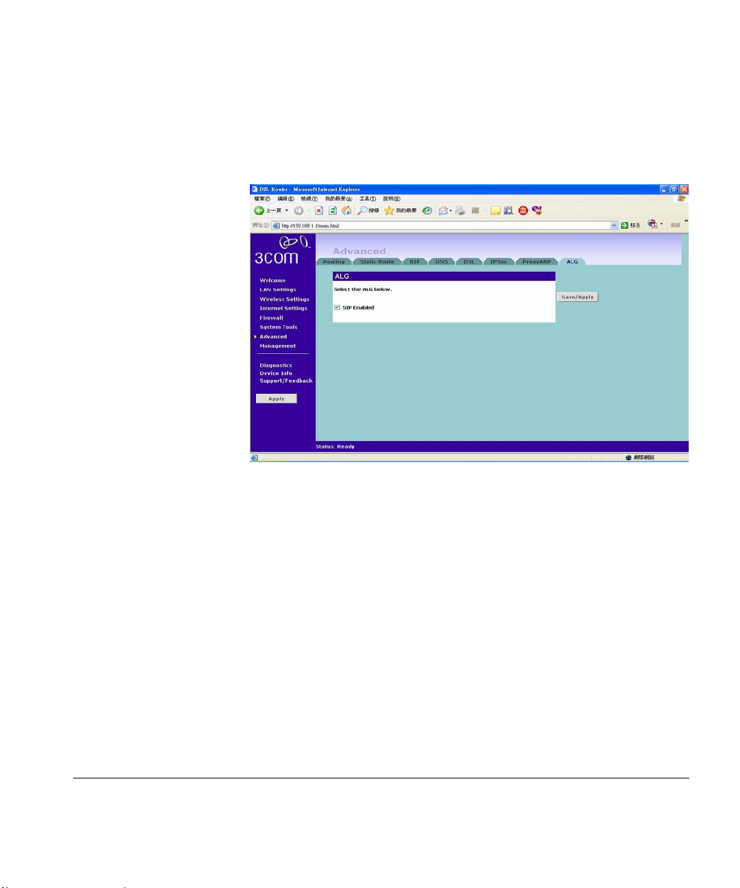
5 In To, type the ending IP address of the IP address range.
Management 77
ALG
Figure 55 The ALG Screen
An Application Layer Gateway (ALG) is a SIP Back to Back User agent
(B2BUA). An ALG can be used to allow firewall traversal with SIP. If the
firewall has it's SIP traffic terminated on an ALG then the responsibility for
permitting SIP sessions is passed onto the ALG instead of the firewall.
It supports access control restrictions, authentication, encryption, etc
Application layer gateways can be made for all application level protoco ls.
They can be used for access control, but also for interworking, for example
between IPv4 and IPv6.
Session Initiation Protocol (SIP) is a protocol developed by the IETF
MMUSIC Working Group and proposed standard for initiating, modifying,
and terminating an interactive user session that involves multimedia elements
such as video, voice, instant messaging, online games, and virtual reality.
Select on the box to enable the ALG feature.
Management The management Screen lets you administer your routers with features such as
system log, SNMP, Access Control, Remote Management.
Page 80
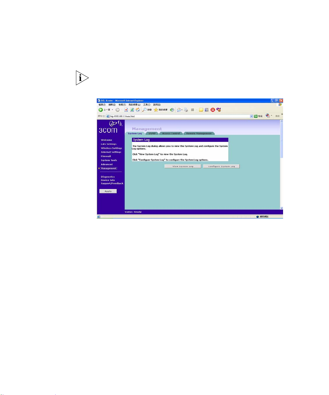
78 CHAPTER 5: ROUTER CONFIGURATION
Syslog If you have a syslog server on the network, you can configure the Router Point
to send the device logs to the server.
You may need to configure the syslog server to accept logs from the Router.
Figure 56 Syslog Screen
To view the current logs:
1 Click on the view the syslogs button.
To send the device logs to a syslog server:
1 Click on Configure syslogs.
2 Click on Enable.
3 Select on the drop-down menu for a list of available types of logging
activities.
4 Select on the Display Level for a list of available types of logging display.
5 Select on the Mode for logging mode: Local, Remote, or Both. For the remote
logging, enter the remote server’s IP address and Port number for receiving
the logs.
Page 81
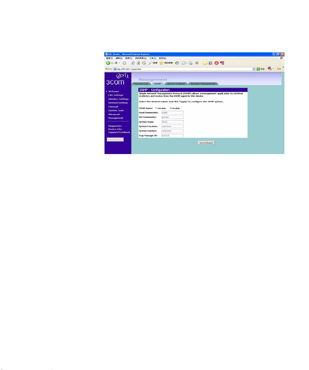
SNMP Figure 57 The SNMP Screen
Simple Network Management Protocol (SNMP) is the protocol used for
exchanging management information between network devices.
Click Enable/Disable to enable/disable the agent.
Management 79
To Configure the SNMP:
1 Type the Read Community, which is the password for the incoming Get and
GetNext requests from the management station.
2 Type the Set Community, which is the password for incoming Set requests
from the management station.
3 Type the System Name for the program.
4 Type the System Location for the program.
5 Type the System Contact for the Contract pe rso n’s name.
6 Type the IP Address of the station/device for sending your SNMP traps to.
Page 82
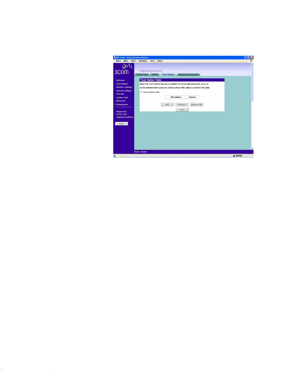
80 CHAPTER 5: ROUTER CONFIGURATION
Trusted Station Figure 58 The Trusted Station Screen
The Trusted Station Screen let you add/remove the MAC address of the
stations which can access the web administration.
Page 83
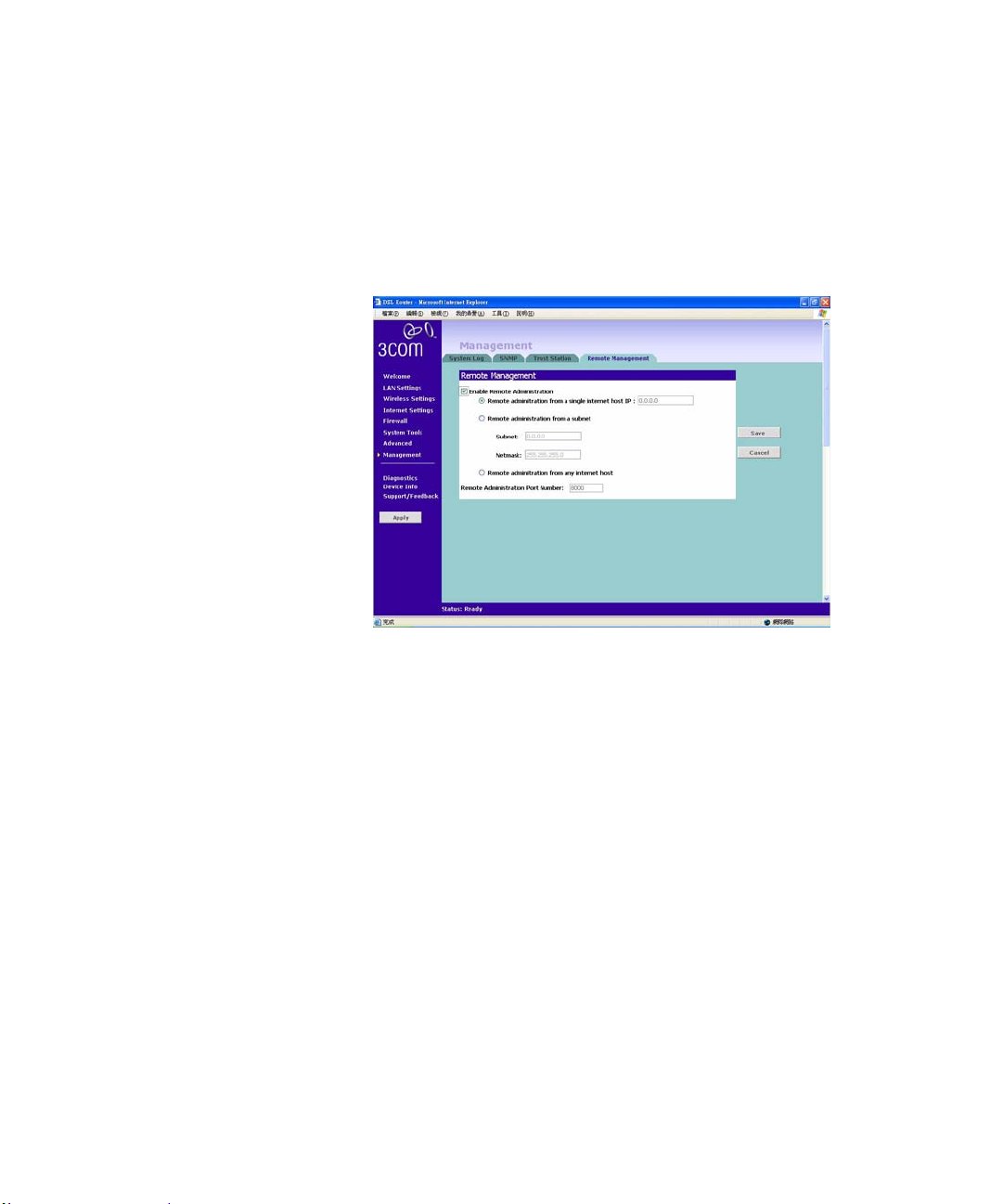
Remote Management Figure 59 The Remote Management Screen
Management 81
It is possible to administer the Router remotely. Select one of the following
options for remote administration:
Disable Remote Administration - This option is set as default.
Enable administration from a single Internet Host - Only the specified
Host IP Address can manage the Router. Any other users will be rejected.
Enable administration from a whole subnet - This option allows a number
of users within the specified Host Network Address and Subnet Mask to
administer the Router.
Enable administration from any Internet Host - This option allows any
host to access the administration pages.
To remotely administer your Router, enter
http://xxx.xxx.xxx.xxx:8000 in the location bar of the browser
running on the remote computer, where xxx.xxx.xxx.xxx is the Internet IP
address of the Router. You may then login using the administration password.
Page 84
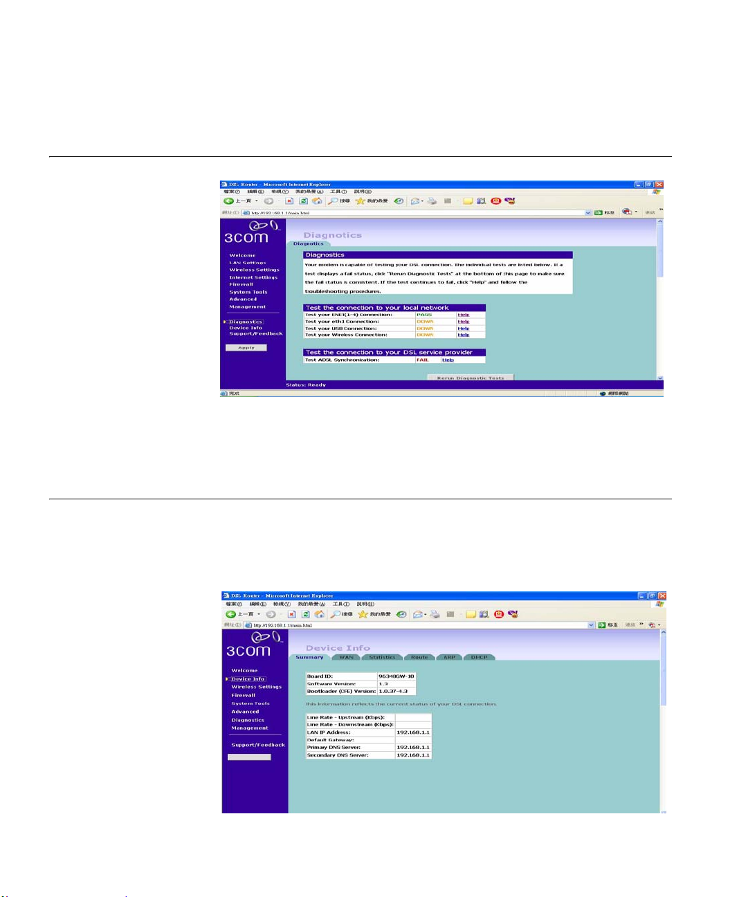
82 CHAPTER 5: ROUTER CONFIGURATION
Diagnostics Figure 60 The Diagnostics Screen
The Diagnostics Screen lets you diagnose your DSL con nection and wired and
wireless networkings. Click on the Test button to start testing.
Device Info The Device Info Settings menu provides the following options:
Figure 61 Summary Screen
Summary
The Summary screen is used to display the information of your LAN status.
Page 85
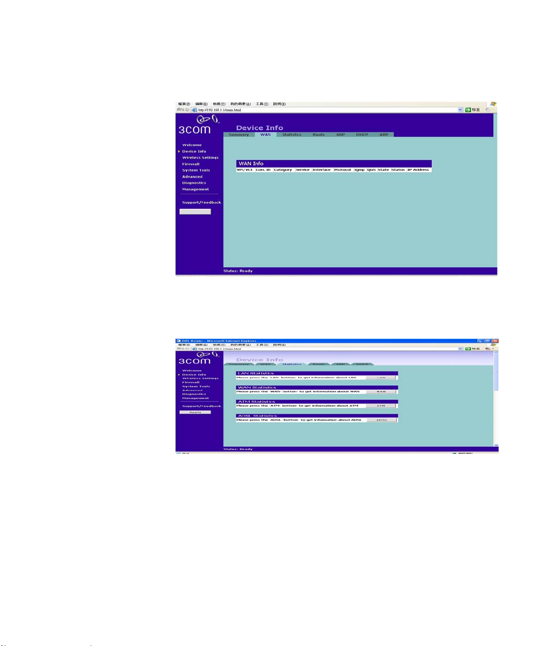
WAN Figure 62 WAN Status Screen
The WAN Status Screen is used to display the information of your DSL
Connection Status.
Device Info 83
Statistics Figure 63 Statistics Screen
The Statistics Screen is used to display the information of your
LAN/WAN/ATM/ADSL Connection Statistics. Click on the button for each
connection device for more detailed information.
Page 86
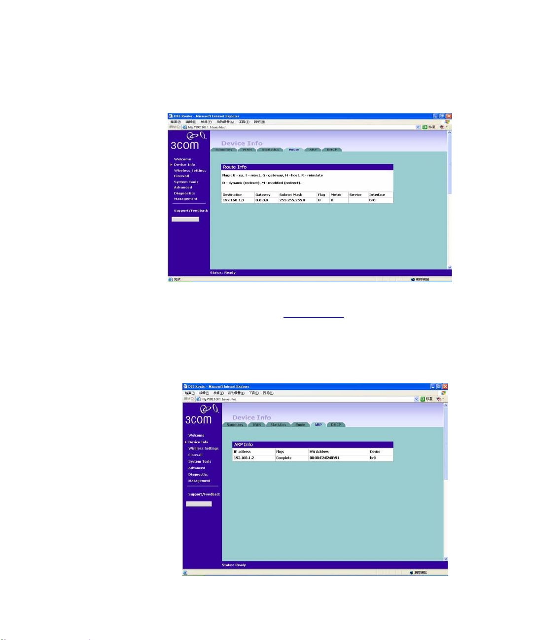
84 CHAPTER 5: ROUTER CONFIGURATION
Route Figure 64 Route Screen
The Route Screen is used to display the routing status/information between
your LAN and WAN. Refer to “
information.
Static Route” in this section for more
ARP Figure 65 ARP Screen
Page 87
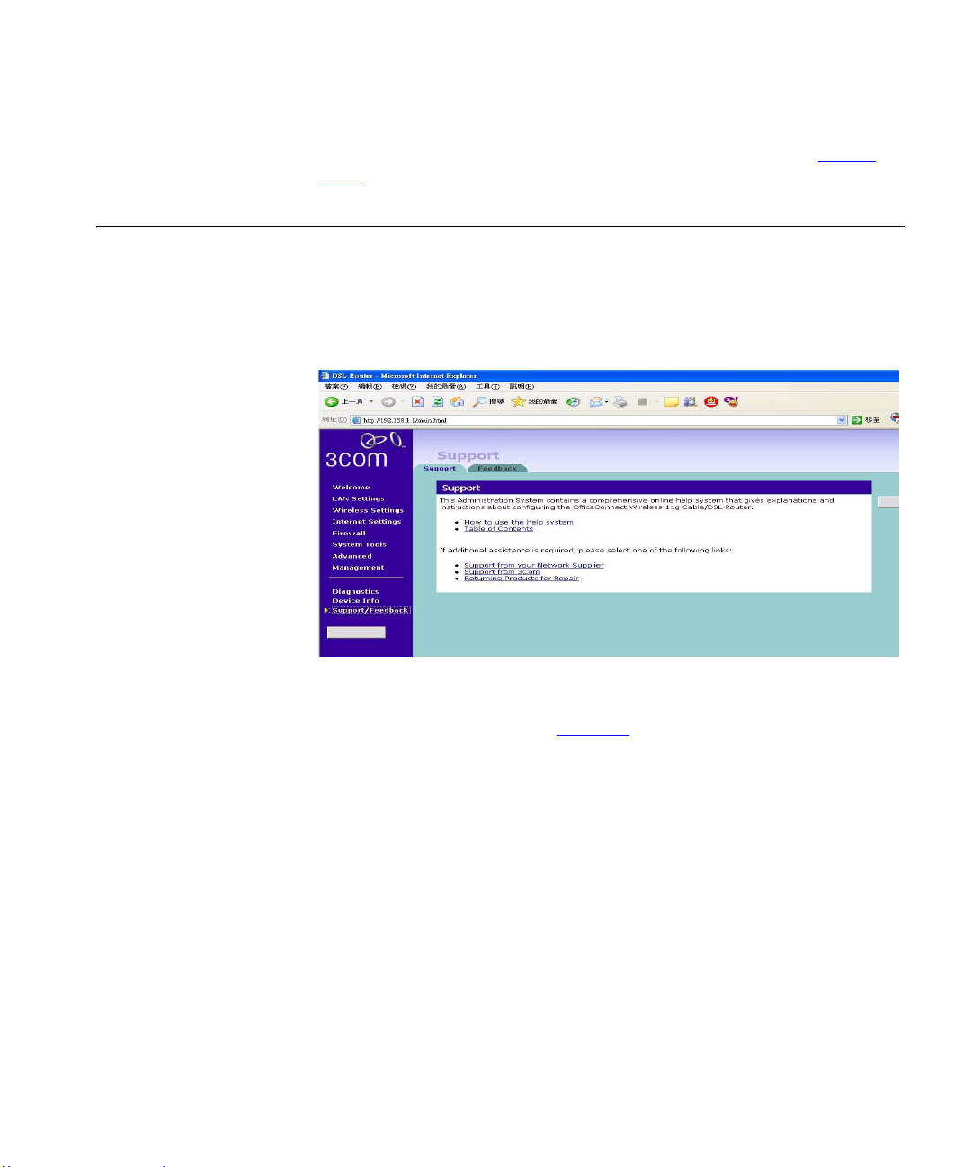
Support/Feedback 85
The ARP screen is used to display the Proxy ARP status. Refer to “Proxy
ARP” in this section for more information.
Support/Feedback Selecting Support/Feedback from the main menu displays the Support and
Feedback screens.
Support Figure 66 Support Screen
Selecting the Support option on the main menu displays the support links
screen, which contains a list of Internet links that provide information and
support concerning the Router (Figure 66
).
Page 88
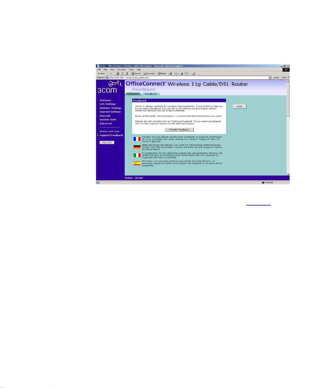
86 CHAPTER 5: ROUTER CONFIGURATION
Feedback Figure 67 Feedback Screen
Selecting the Feedback option displays the Feedback screen and allows you to
provide feedback to 3Com on the operation of your Router (Figure 67
screen should not be used to obtain technical support.
). This
Page 89

6
TROUBLESHOOTING
Basic Connection Checks
Browsing to the Router Configuration
Check that the Router is connected to your computers and to the
cable/DSL modem, and that all the equipment is powered on. Check that the
LAN Status and Cable/DSL Status LEDs on the Router are illuminated, and
that any corresponding LEDs on the cable/DSL modem and the NIC are also
illuminated.
Ensure that the computers have completed their start-up procedure and are
ready for use. Some network interfaces may not be correctly initialized until
the start-up procedure has completed.
If the link status LED does not illuminate for a port that is connected,
check that you do not have a faulty cable. Try a different cable.
If you have connected your Router and computers together but ca nnot brow se
to the Router configuration screens, check the following:
Confirm that the physical connection between your computer and the
Router is OK, and that the LAN Status LEDs on the Router and NIC are
illuminated and indicating the same speed (10Mbps or 100Mbps). Some NICs
do not have status LEDs, in which case a diagnostic program may be available
that can give you this information.
Ensure that you have configured your computer as described in Chapter 3,
Setting Up Your Computers. Restart your computer while it is connected to the
Router to ensure that your computer recei ves an IP address.
When entering th e address of the Router into your web browser, ensure
that you use the full URL including the http:// prefix (e.g.
http://192.168.1.1).
Ensure that you do not have a Web pro xy enabled on your comput er. Go to
the Control Panel and click on Internet Options. Select the Connections tab
Page 90

90 CHAPTER 6: TROUBLESHOOTING
and click on the LAN Settings button at the bottom. Make sure that the Proxy
Server option is unchecked.
If you cannot browse to the Router, use the winipcfg utility in Windows
95/98/ME to verify that your computer has received the correct address
information from the Router. From the Start menu, choose Run and then enter
winipcfg. Check that the computer has an IP address of the form
192.168.1.xxx (where xxx is in the range 2-254), the subnet mask is
255.255.255.0, and the default Router is 192.168.1.1 (the address of the
Router). If these are not correct, use the Release and Renew functions to
obtain a new IP address from the Router. Under Windows 2000, use the
ipconfig command-line utility to perform the same functions.
If you still cannot browse to the Router, then use the Discovery program
on the accompanying CD-ROM as described in Appendix A
.
Connecting to the Internet
If you can browse to the Router configuration screens but cannot access sites
on the Internet, check the following:
Confirm that the physical connection between the Router and the
cable/DSL modem is OK, and that the link status LEDs on both Router and
modem are illuminated.
Confirm that the connection between the modem and the cable/DSL
interface is OK.
Ensure that you have entered the correct informa tion into the Router
configuration screens as required by your Internet Service Provider. Use the
“Internet Settings” screen to verify this.
For DSL users, check that the PPPoE or PPTP user name, password and
service name are correct, if these are required. Only enter a PPPoE service
name if your ISP requires one.
For cable users, check whether your ISP requires a fixed MAC (Ethernet)
address. If so, use the Clone MAC Address feature in the Router to ensure that
the correct MAC address is presented.
For cable users, check whether your ISP requires a fixed Host Name. If so,
enter the required Host Name in the Internet Settings screen.
Page 91
Forgotten Password and Reset to Factory Defaults 91
Ensure that your computers are not configured to use a Web proxy. On
Windows computers, this can be found under Control Panel > Internet
Options > Connections.
Forgotten Password and Reset to Factory Defaults
If you can browse to the Router configuration screen but cannot log on
because you do not know or have forgotten the password, follow the steps
below to reset the Router to it’s factory default configuration.
CAUTION: All your configuration changes will be lost, an d you will need to
run the configuration wizard again before you can re-establish your Router
connection to the Internet. Also, other computer users will lose their network
connections whilst this process is taking place, so choose a time when this
would be convenient.
1 Remove power from the Router.
2 Disconnect all your computers and the cable/DSL modem from the Router.
3 Using a straight through Ethernet cable, connect the Ethernet Cable/DSL port
on the rear of the Router to any one of the LAN ports.
4 Re-apply power to the Router. The Alert LED will flash as the Router starts
up, and after approximately 30 seconds will start to flash more slow ly
(typically 2 seconds on, 2 seconds off). Once the Alert LED has started to
flash slowly, remove power from the Router.
5 Remove the cable connecting the Cable/DSL port to the LAN port, and
reconnect one of your computers to one of the Router LAN ports.
6 Re-apply power to the Router, and when the st art-up seque nce has complet ed,
browse to:
http://192.168.1.1
and run the configuration wizard. You may need to restart your computer
before you attempt this.
7 When the configuration wizard has completed, you may reconnect your
network as it was before.
Wireless Networking Ensure that you have an 802.11b or 802.11g wireless adapter for each
wireless computer, and that it is correctly inst alled and configured. Verify that
each Wireless computer has either Windows 95 or higher or MAC OS 8.5 or
higher.
Page 92

92 CHAPTER 6: TROUBLESHOOTING
Verify that your wireless comput ers are configured to work in
Infrastructure mode and not Ad Hoc mode. The Router contains an Access
Point that is designed to operate in Infrastructure mode. Ad Hoc mode is not
supported by the Router.
If you have a wired and a wireless NIC in the same computer, ensure that
the wired NIC is disabled.
Check the status of the Router Wireless LED, it should be lit if wireless is
enabled and will flash when there is wireless activ ity. If not lit go to “
Settings” and enable wireless networking.
Ensure that th e TCP/IP settings for all devices are correct.
Ensure that the Wireless Clients are using the same SSID or Service Area
Name as the Router. The SSID is case-sensitive
Ensure that the encryption method and level that you use on your clients
are the same as those configured on the Router. The Router can
simultaneously support WPA and WEP encryption, but can only support one
configuration of each.
Wireless
Ensure that you have the Wireless computer enabled in the list of allowed
MAC addresses if you are using Wireless Connection control on the Router.
If you are having difficulty connecting or are operating at a low speed try
changing the antenna positions on the rear of the Router. For more effective
coverage you can try reorientating your antennae. Pla ce one antenna v ertically
and one horizontally to improve coverage. Additionally consider moving the
wireless computer closer to the Router to confirm that the buildin g structure or
fittings are not adversely affecting the connectivity. If this resolves the
problem consider relocating the Wireless computer or the Router, or trying a
different channel on the Router.
Sources of interference: The 2.4Ghz ISM band is used for 802.11b and
802.11g. This is ge nerally a l icence free b and for l ow pow er appli cations, a nd
you may have other devices at your location that operate in this frequency
band. You should take care to ensure that there are no devices like microwave
ovens for example close to the Router or wireless computers as this could
affect receiver sensitivity and reduce the performance of your network. If you
are unsure try relocating both the wireless computers and the Router to
establish whether this problem exists.
Page 93

Power LED or Power Adapter OK LED Not Lit 93
Most wireless computer Adapters will scan the channels for the wireless
Router. If a wireless computer has not located the Router then try initiating a
search manually if the client software supports th is feature or manually set t he
channel on your wireless computer to correspond to the Router chan nel
number. Please refer to your Wireless computer adapter documentation and
vendor to do this.
Speed of connection: The 802.11b and 802.11g standards will
automatically choose the best speed depending on the quality of your
connection. As the signal quality weakens then the speed falls back to a lower
speed. The speeds supported by 802.11g are 54 Mbps, 48 Mbps, 36 Mbps,
24 Mbps, 18 Mbps, 12 Mbps, and 6 Mbps. The speeds supported by 802.11b
are 11 Mbps, 5.5 Mbps, 2 Mbps and 1 Mbps. In general the closer you are to
the Router the better the speed. If you are not achieving the speed you had
anticipated then try moving the antenna on the Router or moving the Wireless
computer closer to the Router. In an ideal network the Router should be
located in the centre of the network with Wireless computers distributed
around it. Applications are generally available with the computer wireless
card to carry out a site survey. Use this application to find the optimal siting
for your wireless computer. Consult your Computer Card documentation and
vendor for more details.
Power LED or Power
Adapter OK LED Not
Lit
Check that your Rout er is receiving power by looking at the status of the
Power LED on the front panel and the Power Adapter OK LED on the rear
panel:
If both LEDs are lit green then the unit is receiving power.
If both LEDs are unlit then no power is being supplied to the unit. Check
that the power adapter is plugged into a working mains outlet and that the
mains outlet is supplying power. If the mains socket is supplying power then
the power adapter or power adapter connection may be faulty. See
Replacement Power Adapters” below.
“
If the Power Adapter OK LED is lit but the Power LED is unlit then there
may be a fault with your unit. Contact 3Com Technical Support.
Check that you are using the correct power adapter for your Router. You
should only use the power adapter supplied with your Router.
Page 94

94 CHAPTER 6: TROUBLESHOOTING
Replacement Power
Adapters
If both the Power Adapter OK LED and Power LED are off, check your
power adapter connection. If the mains outlet is working and is capable of
supplying power to other devices, contact 3Com Technical Support and ask
for a replacement power adapter. Please quote the power adapter part number
shown on the OfficeConnect power ada pt er you are usin g.
Alternatively, quote the part number for your region:
Power Adapter Part Numbers
Part Number Region
3C16760 US and Canada
3C16761 UK
3C16762 Europe and Middle East
3C16763 Australasia (except Japan and Korea)
3C16764 South Africa
3C16766 Japan
3C16767 Korea
3C16768 Argentina
Alert LED The Alert LED will flash when the Router unit is first powered up while the
system software checks the hardware for proper operation. Once the Router
has started normal operation, the Alert LED will go out.
If the Alert LED does not go out following start up, but illuminates
continuously , this indicates that the software has detecte d a possible fault with
the hardware. Remove power from the Router, wait 10 seconds and then
re-apply power. If the Alert LED comes on continuously again, then a fault
has been detected. Locate the copy of the Router software on the
accompanying CD-ROM or 3Com web site (
upload it to the Router to see if this clears the fault (refer to “Rec overing from
Corrupted Software” below). If this does not fix the problem, co ntact your
supplier for further advice.
During normal operation, you may notice the Alert LED lighting briefly
from time to time. This indicates that the Router has detected a hacker attack
from the Internet and has prevented it from harming your network. You need
take no specific action on this, unless you decide that these attacks are
happening frequently in which case you may wish to discuss this with your
http://www.3com.com) and
Page 95
Recovering from Corrupted Software 95
ISP. The Router logs such attacks, and this information is available through
the Status and Logs screens.
Recovering from Corrupted Software
If the Alert LED remains permanently on following power-up, it is possible
that the system software has become corrupted. In this condition, the Router
will enter a “recovery” state; DHCP is disabled, and the LAN IP address is set
to 192.168.1.1. Follow the instructions below to upload a new copy of the
system software to a Router unit in this state.
Ensure that one of your computers has a copy of the new software image file
stored on its hard disk or available on CD-ROM.
The latest software is available on 3Com’s Web site at:
www.3com.com.
1 Remove power from the Router and disconnect the Cable/DSL modem and all
your computers, except for the one computer with the software image.
2 You will need to reconfigure this computer with the following static IP
address information:
IP address: 192.168.1.2
Subnet mask: 255 .255.255.0
Default Router address: 192.168.1.1
3 Restart the computer, and re-apply power to the Router .
4 Using the Web browser on the computer, enter the following URL in the
location bar:
http://192.168.1.1.
This will connect you to the Microcode Recovery utility in the Router.
5 Follow the on-screen instructions. Enter the path and filename of the software
image file.
6 When the upload has completed, the Router will restart, run the self-test and,
if successful, resume normal operation. The Alert LED will go out.
7 Refer to the Installation Guide to reconnect your Router to the Cable/DSL
modem and the computers in your network. Do not forget to reconfigure the
computer you used for the software upload.
Page 96

96 CHAPTER 6: TROUBLESHOOTING
If the Router does not resume normal operation following the upload, it may
be faulty. Contact your supplier for advice.
Frequently Asked Questions
How do I reset the Router to Factory Defaults?
Forgotten Password and Reset to Factory Defaults ” on page 91.
See “
How many computers on the LAN does the Router support?
A maximum of 253 computers on the LAN are supported.
How many wireless clients does the Cable/DSL Router support?
A maximum of 128 wireless clients are supported.
There are only 4 LAN ports on the Router. How are additional computers
connected?
You can expand the number of connections available on your LAN by
using hubs, switches and wireless access points connected to the
Router. 3Com wireless access points and OfficeConnect hubs and
switches provide a simple, reliable means of expanding your network;
contact your supplier for more information, or visit:
http://www.3com.com/
Does the Router support virtual private networks (VPNs)?
The Router supports VPN passthrough, which allows VPN clients on
the LAN to communicate with VPN hosts on the Internet. It is also
possible to set up VPN hosts on your LAN that clients elsewhere on the
Internet can connect to, but this is not a recommended configuration.
Where can I download software updates for the Router?
Updates to the Router software are posted on the 3Com support web
site, accessible by visiting:
http://www.3com.com
What other online resources are there?
The 3Com Knowledgebase at:
http://knowledgebase.3com.com
Page 97

Frequently Asked Questions 97
is a database of technical information coverin g all 3Com prod ucts. It is
updated daily with information from 3Com technical support services,
and it is available 24 hours a day, 7 days a week.
Page 98

98 CHAPTER 6: TROUBLESHOOTING
Page 99
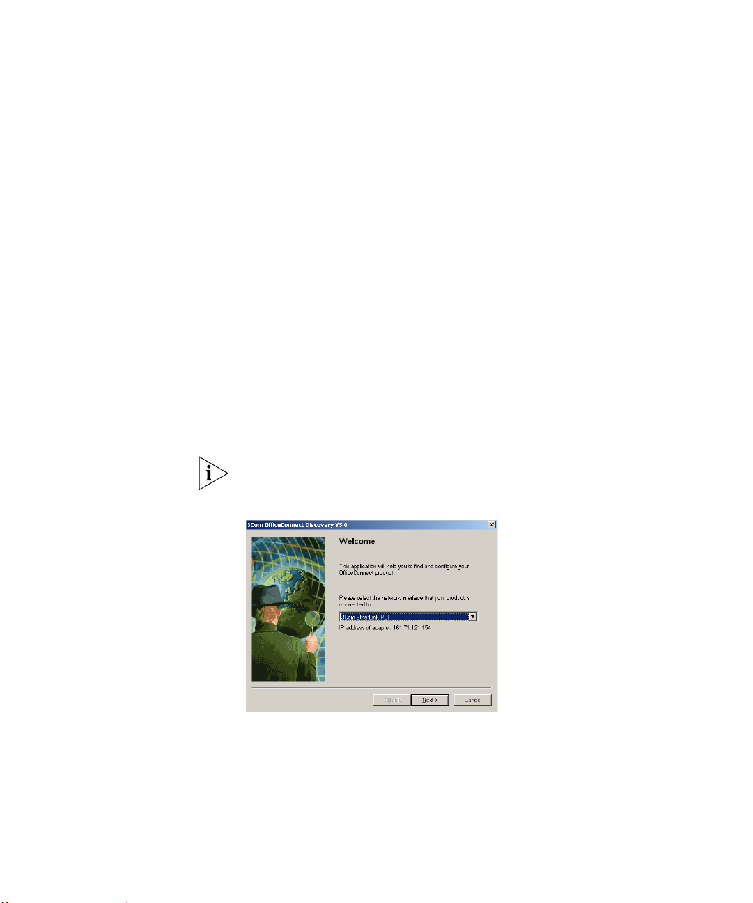
A
USING DISCOVERY
Running the Discovery Application
Windows Installation
(95/98/2000/Me/NT)
3Com provides a user friendly Discovery application for detecting the Router
on the network.
1 Insert the Router CD-ROM in the CD-ROM drive on your computer. A menu
will appear; select Router Discovery.
Discovery will find the Router even if it is unconfigured or misconfigured.
Figure 71 Discovery Welcome Screen
2 When the Welcome screen is displayed click on Next and wait until the
application discovers the Routers connected to your LAN.
Page 100
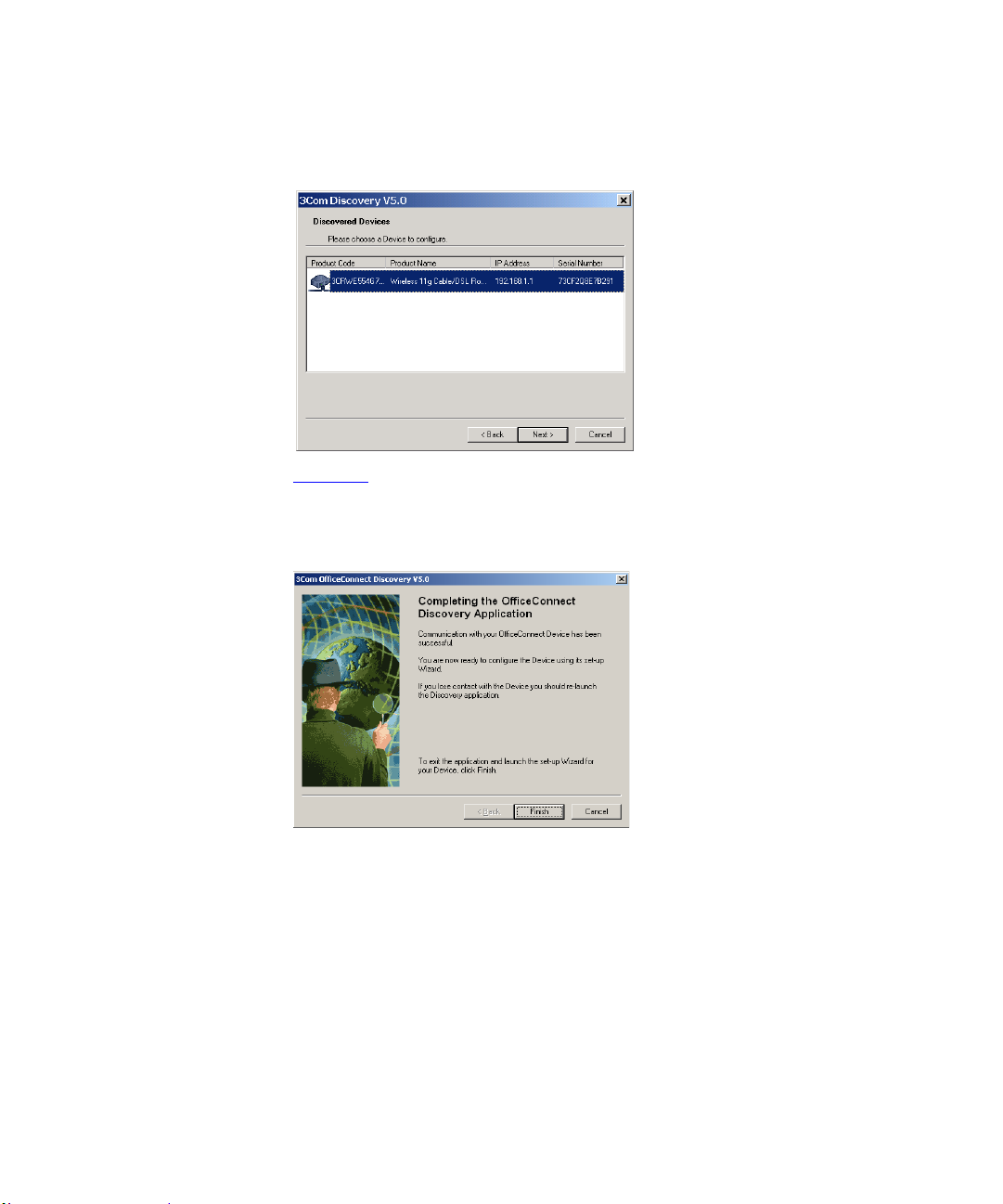
98 APPENDIX A: USING DISCOVERY
Figure 72 Discovered Router Screen
3 Figure 73 shows an example Discovered Devices screen. Highlight the
Cable/DSL Router by clicking on it, and press Next.
Figure 73 Discovery Finish Screen
4 Click on Finish to launch a web browser and display the login page for the
Router.
 Loading...